EP4166970A1 - Position detection marker for magnetic resonance imaging - Google Patents
Position detection marker for magnetic resonance imaging Download PDFInfo
- Publication number
- EP4166970A1 EP4166970A1 EP22201879.8A EP22201879A EP4166970A1 EP 4166970 A1 EP4166970 A1 EP 4166970A1 EP 22201879 A EP22201879 A EP 22201879A EP 4166970 A1 EP4166970 A1 EP 4166970A1
- Authority
- EP
- European Patent Office
- Prior art keywords
- marker
- position detection
- magnetic field
- mri
- field source
- Prior art date
- Legal status (The legal status is an assumption and is not a legal conclusion. Google has not performed a legal analysis and makes no representation as to the accuracy of the status listed.)
- Pending
Links
Images


Classifications
-
- G—PHYSICS
- G01—MEASURING; TESTING
- G01R—MEASURING ELECTRIC VARIABLES; MEASURING MAGNETIC VARIABLES
- G01R33/00—Arrangements or instruments for measuring magnetic variables
- G01R33/20—Arrangements or instruments for measuring magnetic variables involving magnetic resonance
- G01R33/28—Details of apparatus provided for in groups G01R33/44 - G01R33/64
-
- A—HUMAN NECESSITIES
- A61—MEDICAL OR VETERINARY SCIENCE; HYGIENE
- A61B—DIAGNOSIS; SURGERY; IDENTIFICATION
- A61B90/00—Instruments, implements or accessories specially adapted for surgery or diagnosis and not covered by any of the groups A61B1/00 - A61B50/00, e.g. for luxation treatment or for protecting wound edges
- A61B90/39—Markers, e.g. radio-opaque or breast lesions markers
-
- G—PHYSICS
- G01—MEASURING; TESTING
- G01R—MEASURING ELECTRIC VARIABLES; MEASURING MAGNETIC VARIABLES
- G01R33/00—Arrangements or instruments for measuring magnetic variables
- G01R33/20—Arrangements or instruments for measuring magnetic variables involving magnetic resonance
- G01R33/44—Arrangements or instruments for measuring magnetic variables involving magnetic resonance using nuclear magnetic resonance [NMR]
- G01R33/48—NMR imaging systems
- G01R33/58—Calibration of imaging systems, e.g. using test probes, Phantoms; Calibration objects or fiducial markers such as active or passive RF coils surrounding an MR active material
-
- A—HUMAN NECESSITIES
- A61—MEDICAL OR VETERINARY SCIENCE; HYGIENE
- A61B—DIAGNOSIS; SURGERY; IDENTIFICATION
- A61B90/00—Instruments, implements or accessories specially adapted for surgery or diagnosis and not covered by any of the groups A61B1/00 - A61B50/00, e.g. for luxation treatment or for protecting wound edges
- A61B90/39—Markers, e.g. radio-opaque or breast lesions markers
- A61B2090/3954—Markers, e.g. radio-opaque or breast lesions markers magnetic, e.g. NMR or MRI
- A61B2090/3958—Markers, e.g. radio-opaque or breast lesions markers magnetic, e.g. NMR or MRI emitting a signal
-
- G—PHYSICS
- G01—MEASURING; TESTING
- G01R—MEASURING ELECTRIC VARIABLES; MEASURING MAGNETIC VARIABLES
- G01R33/00—Arrangements or instruments for measuring magnetic variables
- G01R33/0094—Sensor arrays
-
- G—PHYSICS
- G01—MEASURING; TESTING
- G01R—MEASURING ELECTRIC VARIABLES; MEASURING MAGNETIC VARIABLES
- G01R33/00—Arrangements or instruments for measuring magnetic variables
- G01R33/02—Measuring direction or magnitude of magnetic fields or magnetic flux
- G01R33/10—Plotting field distribution ; Measuring field distribution
Definitions
- the present invention relates to a position detection marker and, more particularly, to a position detection marker capable of being used for both a magnetic measuring apparatus and a magnetic resonance imaging apparatus.
- a magnetic measuring apparatus for measuring magnetic field distribution in a predetermined space or plane has a plurality of magnetic sensors.
- Magnetic measuring apparatuses described in JP 2001-037732A and JP 2020-198925A use a position detection marker to recognize the relative positional relation between the plurality of magnetic sensors and an object to be measured.
- the position detection markers described in JP 2001-037732A and JP 2020-198925A are constituted by a coil and thus cannot be photographed by a magnetic resonance imaging method.
- a magnetic resonance imaging method when the same object to be measured is measured by both the magnetic measuring apparatus and a magnetic resonance imaging apparatus, an image generated by the magnetic measuring apparatus and an image generated by the magnetic resonance imaging apparatus cannot be superimposed accurately.
- a position detection marker includes: a magnetic field source that generates magnetism; an MRI marker that can be detected by a magnetic resonance imaging method; and a holding part that fixes the relative positional relation between the magnetic field source and the MRI marker.
- the magnetic field source which is a marker for a magnetic measuring apparatus and the MRI marker which is a marker for a magnetic resonance imaging apparatus are fixed by the holding part, thus making it possible to accurately superimpose an image generated by the magnetic measuring apparatus and an image generated by the magnetic resonance imaging apparatus.
- the magnetic field source may be a coil.
- the coil allows generation of an AC magnetic field and is thus suitable as a marker for the magnetic measuring apparatus.
- the position detection marker according to the present invention may further include a connector to/from which a cable can be attached/detached. This allows the cable to be detached when measurement is performed using the magnetic resonance imaging apparatus, so that heat generation in the coil can be prevented.
- the MRI marker may be disposed in the inner diameter area of the coil. This makes it possible to make the generation position of the AC magnetic field and the position of the MRI marker coincide with each other.
- the holding part may have a configuration allowing attachment/detachment of the magnetic field source and MRI marker. This facilitates the exchange of the magnetic field source and MRI marker, improving maintainability.
- the holding part may include a housing part housing therein the magnetic field source and MRI marker and a lid part closing the housing part, and the housing part and lid part may be fixed to each other by screw engagement or claw engagement. This facilitates detachment of the lid part.
- a position detection marker capable of being used for both the magnetic measuring apparatus and magnetic resonance imaging apparatus.
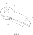
- FIG. 1 is a schematic perspective view illustrating the outer appearance of a position detection marker 1 according to an embodiment of the present invention.
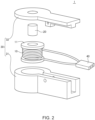
- FIG. 2 is a schematic exploded perspective view of the position detection marker 1.
- the position detection marker 1 includes a coil 10 serving as a magnetic field source, an MRI marker 20, and a holding part 30 holding the coil 10 and MRI marker 20.
- the coil 10 is formed by a wire wound around a bobbin 11, and both ends thereof are connected to a connector 40.
- the MRI marker 20 is a capsule or a tablet made of a moisture-containing substance so as to be detected by a magnetic resonance imaging method and is inserted into a cylindrical winding core part of the bobbin 11. Accordingly, the MRI marker 20 is disposed in the inner diameter area of the coil 10.
- the holding part 30 fixes the relative positional relation between the coil 10 and the MRI marker 20 and includes a housing part 31 housing therein the coil 10 and MRI marker 20 and a lid part 32 closing the housing part 31.
- the housing part 31 and lid part 32 each have a screw hole, and a screw 50 is screwed into the screw holes to fix the housing part 31 and lid part 32.
- the MRI marker 20 is inserted into the winding core part of the bobbin 11 wound with the coil 10, whereby the relative positional relation between the coil 10 and the MRI marker 20 is fixed, so that, in this case, the bobbin 11 may be regarded as a "holding part".
- FIG. 3 is a schematic view for explaining an example of a measuring method using the position detection marker 1.
- an object to be measured is a human body
- the position detection marker 1 is fixed to a plurality of portions of the human body. Specifically, four position detection markers 1 are fixed to the chest. There is no particular restriction on the fixing method of the position detection marker 1, and the position detection marker 1 may be fixed by using, e.g., an adhesive tape.
- the magnetic measuring apparatus has a plurality of magnetic sensors to thereby measure magnetic field distribution in a predetermined space or plane.
- a cable is connected to the connector 40, and AC having a predetermined frequency is supplied to the coil 10.
- an AC magnetic field is generated from the coil 10.
- marker points 1a are superimposed on an image P of the object to be measured.
- photographing is performed with the cable detached from the connector 40.
- marker points 1b are superimposed on an image Q of the object to be measured.
- the images are superimposed so as to make the marker points 1a and 1b coincide with each other, thereby obtaining a synthesized image PQ in which the image P generated by the magnetic measuring apparatus and the image Q generated by the magnetic resonance imaging apparatus are superimposed accurately.
- the coil is in an open state, thereby preventing the coil 10 from being excessively heated by a strong magnetic field generated from the magnetic resonance imaging apparatus.
- the holding part 30 is constituted by the housing part 31 and lid part 32, and they are fixed by the screw, allowing attachment/detachment of the coil 10 and MRI marker 20. This achieves high maintainability.
- FIG. 5 is a schematic perspective view for explaining the structure of a holding part 30A according to a first modification.
- the holding part 30A illustrated in FIG. 5 is featured in that a housing part 31A and a lid part 32A are fixed through a hinge 33 and that a claw part 34 provided in the housing part 31A is hooked on an annular part 35 provided in the lid part 32A to fix the housing part 31A and lid part 32A. This eliminates the need to use a screw, allowing a reduction in the number of components.
- FIG. 6 is a schematic perspective view for explaining the structure of a holding part 30B according to a second modification.
- the holding part 30B illustrated in FIG. 6 is featured in that male and female screws 36 and 37 are formed in the outer peripheral wall of a housing part 31B and the inner peripheral wall of a lid part 32B, respectively. By engaging the male and female screws 36 and 37 with each other, the housing part 31B and the lid part 32B are fixed to each other. With this configuration as well, the number of components can be reduced.
- any other magnetic field source than the coil may be used as long as it generates magnetism that can be detected by the magnetic measuring apparatus.
- the MRI marker is disposed in the inner diameter area of the coil in the above embodiment, there is no particular restriction on the positional relation between the magnetic field source and the MRI marker as long as the relative positional relation therebetween is fixed.
Landscapes
- Physics & Mathematics (AREA)
- Health & Medical Sciences (AREA)
- Condensed Matter Physics & Semiconductors (AREA)
- General Physics & Mathematics (AREA)
- Surgery (AREA)
- Life Sciences & Earth Sciences (AREA)
- High Energy & Nuclear Physics (AREA)
- Engineering & Computer Science (AREA)
- Pathology (AREA)
- Oral & Maxillofacial Surgery (AREA)
- Nuclear Medicine, Radiotherapy & Molecular Imaging (AREA)
- Biomedical Technology (AREA)
- Heart & Thoracic Surgery (AREA)
- Medical Informatics (AREA)
- Molecular Biology (AREA)
- Animal Behavior & Ethology (AREA)
- General Health & Medical Sciences (AREA)
- Public Health (AREA)
- Veterinary Medicine (AREA)
- Magnetic Resonance Imaging Apparatus (AREA)
Abstract
Description
- The present invention relates to a position detection marker and, more particularly, to a position detection marker capable of being used for both a magnetic measuring apparatus and a magnetic resonance imaging apparatus.
- A magnetic measuring apparatus for measuring magnetic field distribution in a predetermined space or plane has a plurality of magnetic sensors. Magnetic measuring apparatuses described in
JP 2001-037732A JP 2020-198925A - However, the position detection markers described in
JP 2001-037732A JP 2020-198925A - It is therefore an object of the present invention to provide a position detection marker capable of being used both for the magnetic measuring apparatus and magnetic resonance imaging apparatus.
- A position detection marker according to the present invention includes: a magnetic field source that generates magnetism; an MRI marker that can be detected by a magnetic resonance imaging method; and a holding part that fixes the relative positional relation between the magnetic field source and the MRI marker.
- According to the present invention, the magnetic field source which is a marker for a magnetic measuring apparatus and the MRI marker which is a marker for a magnetic resonance imaging apparatus are fixed by the holding part, thus making it possible to accurately superimpose an image generated by the magnetic measuring apparatus and an image generated by the magnetic resonance imaging apparatus.
- In the present invention, the magnetic field source may be a coil. The coil allows generation of an AC magnetic field and is thus suitable as a marker for the magnetic measuring apparatus. In this case, the position detection marker according to the present invention may further include a connector to/from which a cable can be attached/detached. This allows the cable to be detached when measurement is performed using the magnetic resonance imaging apparatus, so that heat generation in the coil can be prevented. Further, the MRI marker may be disposed in the inner diameter area of the coil. This makes it possible to make the generation position of the AC magnetic field and the position of the MRI marker coincide with each other.
- In the present invention, the holding part may have a configuration allowing attachment/detachment of the magnetic field source and MRI marker. This facilitates the exchange of the magnetic field source and MRI marker, improving maintainability. In this case, the holding part may include a housing part housing therein the magnetic field source and MRI marker and a lid part closing the housing part, and the housing part and lid part may be fixed to each other by screw engagement or claw engagement. This facilitates detachment of the lid part.
- As described above, according to the present invention, there can be provided a position detection marker capable of being used for both the magnetic measuring apparatus and magnetic resonance imaging apparatus.
- The above and other objects, features and advantages of this invention will become more apparent by reference to the following detailed description of the invention taken in conjunction with the accompanying drawings, wherein:
-
FIG. 1 is a schematic perspective view illustrating the outer appearance of aposition detection marker 1 according to an embodiment of the present invention; -
FIG. 2 is a schematic exploded perspective view of theposition detection marker 1; -
FIG. 3 is a schematic view for explaining an example of a measuring method using theposition detection marker 1 ; -
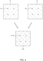
FIG. 4 is schematic view for explaining superimposing an image P on an image Q; -
FIG. 5 is a schematic perspective view for explaining the structure of aholding part 30A according to a first modification; and -
FIG. 6 is a schematic perspective view for explaining the structure of aholding part 30B according to a second modification. - Preferred embodiments of the present invention will now be explained in detail with reference to the drawings.
-
FIG. 1 is a schematic perspective view illustrating the outer appearance of aposition detection marker 1 according to an embodiment of the present invention.FIG. 2 is a schematic exploded perspective view of theposition detection marker 1. - As illustrated in
FIGS. 1 and2 , theposition detection marker 1 according to the present embodiment includes acoil 10 serving as a magnetic field source, anMRI marker 20, and aholding part 30 holding thecoil 10 andMRI marker 20. Thecoil 10 is formed by a wire wound around abobbin 11, and both ends thereof are connected to aconnector 40. Thus, when an AC is supplied to thecoil 10 through an external cable connected to theconnector 40, an AC magnetic field can be generated from thecoil 10. TheMRI marker 20 is a capsule or a tablet made of a moisture-containing substance so as to be detected by a magnetic resonance imaging method and is inserted into a cylindrical winding core part of thebobbin 11. Accordingly, theMRI marker 20 is disposed in the inner diameter area of thecoil 10. - The
holding part 30 fixes the relative positional relation between thecoil 10 and theMRI marker 20 and includes ahousing part 31 housing therein thecoil 10 andMRI marker 20 and alid part 32 closing thehousing part 31. As illustrated inFIG. 2 , thehousing part 31 andlid part 32 each have a screw hole, and ascrew 50 is screwed into the screw holes to fix thehousing part 31 andlid part 32. However, in the example illustrated inFIG. 2 , theMRI marker 20 is inserted into the winding core part of thebobbin 11 wound with thecoil 10, whereby the relative positional relation between thecoil 10 and theMRI marker 20 is fixed, so that, in this case, thebobbin 11 may be regarded as a "holding part". -
FIG. 3 is a schematic view for explaining an example of a measuring method using theposition detection marker 1. - In the example illustrated in
FIG. 3 , an object to be measured is a human body, and theposition detection marker 1 is fixed to a plurality of portions of the human body. Specifically, fourposition detection markers 1 are fixed to the chest. There is no particular restriction on the fixing method of theposition detection marker 1, and theposition detection marker 1 may be fixed by using, e.g., an adhesive tape. - In a state where the plurality of
position detection markers 1 are fixed to the object to be measured, measurement using a magnetic measuring apparatus and measurement using a magnetic resonance imaging apparatus are sequentially performed. The magnetic measuring apparatus has a plurality of magnetic sensors to thereby measure magnetic field distribution in a predetermined space or plane. When performing measurement using the magnetic measuring apparatus, a cable is connected to theconnector 40, and AC having a predetermined frequency is supplied to thecoil 10. As a result, an AC magnetic field is generated from thecoil 10. Thus, in a measured image obtained from the magnetic measuring apparatus illustrated inFIG. 4 ,marker points 1a are superimposed on an image P of the object to be measured. Further, when performing measurement using the magnetic resonance imaging apparatus, photographing is performed with the cable detached from theconnector 40. In a measured image obtained from the magnetic resonance imaging apparatus illustrated inFIG. 4 , marker points 1b are superimposed on an image Q of the object to be measured. - Then, as illustrated in
FIG. 4 , the images are superimposed so as to make themarker points 1a and 1b coincide with each other, thereby obtaining a synthesized image PQ in which the image P generated by the magnetic measuring apparatus and the image Q generated by the magnetic resonance imaging apparatus are superimposed accurately. Further, since the measurement using the magnetic resonance imaging apparatus is performed with the cable detached from theconnector 40, the coil is in an open state, thereby preventing thecoil 10 from being excessively heated by a strong magnetic field generated from the magnetic resonance imaging apparatus. Furthermore, theholding part 30 is constituted by thehousing part 31 andlid part 32, and they are fixed by the screw, allowing attachment/detachment of thecoil 10 andMRI marker 20. This achieves high maintainability. -
FIG. 5 is a schematic perspective view for explaining the structure of aholding part 30A according to a first modification. Theholding part 30A illustrated inFIG. 5 is featured in that ahousing part 31A and alid part 32A are fixed through ahinge 33 and that aclaw part 34 provided in thehousing part 31A is hooked on anannular part 35 provided in thelid part 32A to fix thehousing part 31A andlid part 32A. This eliminates the need to use a screw, allowing a reduction in the number of components. -
FIG. 6 is a schematic perspective view for explaining the structure of aholding part 30B according to a second modification. Theholding part 30B illustrated inFIG. 6 is featured in that male andfemale screws housing part 31B and the inner peripheral wall of alid part 32B, respectively. By engaging the male andfemale screws housing part 31B and thelid part 32B are fixed to each other. With this configuration as well, the number of components can be reduced. - While the preferred embodiment of the present invention has been described, the present invention is not limited to the above embodiment, and various modifications may be made within the scope of the present invention, and all such modifications are included in the present invention.
- For example, although a coil is used as a magnetic field source in the above embodiment, any other magnetic field source than the coil may be used as long as it generates magnetism that can be detected by the magnetic measuring apparatus. Further, although the MRI marker is disposed in the inner diameter area of the coil in the above embodiment, there is no particular restriction on the positional relation between the magnetic field source and the MRI marker as long as the relative positional relation therebetween is fixed.
Claims (8)
- A position detection marker comprising:a magnetic field source that generates magnetism;an MRI marker that can be detected by a magnetic resonance imaging method; anda holding part that fixes a relative positional relation between the magnetic field source and the MRI marker.
- The position detection marker as claimed in claim 1, wherein the magnetic field source is a coil.
- The position detection marker as claimed in claim 2, further comprising a connector to/from which a cable can be attached/detached.
- The position detection marker as claimed in claim 2 or 3, wherein the MRI marker is disposed in an inner diameter area of the coil.
- The position detection marker as claimed in any one of claims 1 to 4, wherein the holding part has a configuration allowing attachment/detachment of the magnetic field source and MRI marker.
- The position detection marker as claimed in claim 5,wherein the holding part includes a housing part housing therein the magnetic field source and MRI marker and a lid part closing the housing part, andwherein the housing part and lid part are fixed to each other by screw engagement or claw engagement.
- The position detection marker as claimed in claim 5,wherein the holding part includes a housing part housing therein the magnetic field source and MRI marker and a lid part closing the housing part, andwherein the lid has an opening exposing the MRI marker.
- The position detection marker as claimed in claim 7, wherein the MRI marker protrudes from the opening of the lid.
Applications Claiming Priority (1)
| Application Number | Priority Date | Filing Date | Title |
|---|---|---|---|
| JP2021170292A JP7727480B2 (en) | 2021-10-18 | 2021-10-18 | Position detection marker |
Publications (1)
| Publication Number | Publication Date |
|---|---|
| EP4166970A1 true EP4166970A1 (en) | 2023-04-19 |
Family
ID=83898421
Family Applications (1)
| Application Number | Title | Priority Date | Filing Date |
|---|---|---|---|
| EP22201879.8A Pending EP4166970A1 (en) | 2021-10-18 | 2022-10-17 | Position detection marker for magnetic resonance imaging |
Country Status (4)
| Country | Link |
|---|---|
| US (1) | US12070364B2 (en) |
| EP (1) | EP4166970A1 (en) |
| JP (1) | JP7727480B2 (en) |
| CN (1) | CN115990009A (en) |
Citations (6)
| Publication number | Priority date | Publication date | Assignee | Title |
|---|---|---|---|---|
| JP2001037732A (en) | 1999-07-29 | 2001-02-13 | Kanazawa Inst Of Technology | Biomagnetic measurement device |
| JP2002253531A (en) * | 2001-03-05 | 2002-09-10 | Yokogawa Electric Corp | Marker coil |
| US20100056901A1 (en) * | 2007-05-11 | 2010-03-04 | Pulseteq Limited | Apparatus and method for magnetic resonance scanning |
| US20130249560A1 (en) * | 2011-05-20 | 2013-09-26 | Toshiba Medical Systems Corporation | Magnetic resonance imaging apparatus |
| US20150035533A1 (en) * | 2012-02-14 | 2015-02-05 | Koninklijke Philips N.V. | Active position marker system for use in an mri apparatus |
| JP2020198925A (en) | 2019-06-06 | 2020-12-17 | 学校法人金沢工業大学 | Marker coil and magnetic measurement device |
Family Cites Families (14)
| Publication number | Priority date | Publication date | Assignee | Title |
|---|---|---|---|---|
| JP3473210B2 (en) * | 1995-08-31 | 2003-12-02 | 株式会社島津製作所 | Biomagnetic measurement device |
| US6690168B1 (en) * | 1999-02-22 | 2004-02-10 | Allen Ray Herron | Biomagnetic detecting and imaging device |
| JP3454235B2 (en) * | 1999-10-06 | 2003-10-06 | 株式会社日立製作所 | Biomagnetic field measurement device |
| JP2004329726A (en) * | 2003-05-12 | 2004-11-25 | Hitachi Ltd | Surgical equipment |
| US7756579B2 (en) * | 2005-02-22 | 2010-07-13 | Depuy International Ltd. | Implantable sensor |
| WO2007039842A2 (en) * | 2005-10-06 | 2007-04-12 | Koninklijke Philips Electronics N.V. | Mr coil with fiber optical connection |
| JP5572294B2 (en) * | 2008-07-25 | 2014-08-13 | 株式会社エム・アール・テクノロジー | Nuclear magnetic resonance imaging system |
| US20100305402A1 (en) * | 2009-05-29 | 2010-12-02 | Magnetecs,Inc. | Method and apparatus for magnetic waveguide forming a shaped field employing a magnetic aperture for guiding and controlling a medical device |
| WO2015061343A1 (en) * | 2013-10-22 | 2015-04-30 | Rock West Solutions, Inc. | System to localize swallowable pill sensor with three transmitting elements |
| RU2665343C1 (en) * | 2013-12-10 | 2018-08-29 | Конинклейке Филипс Н.В. | Magnetic resonance coil assembly for fiducial markers |
| WO2016058076A1 (en) * | 2014-10-14 | 2016-04-21 | Synaptive Medical (Barbados) Inc. | Patient reference tool |
| JP2018121666A (en) * | 2015-04-28 | 2018-08-09 | 国立大学法人九州大学 | Measuring device and measuring method |
| JP7069563B2 (en) * | 2016-06-07 | 2022-05-18 | 株式会社リコー | Marker coil, marker coil unit |
| US11170921B2 (en) * | 2016-06-07 | 2021-11-09 | Ricoh Company, Ltd. | Marker coil and marker coil unit |
-
2021
- 2021-10-18 JP JP2021170292A patent/JP7727480B2/en active Active
-
2022
- 2022-10-12 US US17/964,826 patent/US12070364B2/en active Active
- 2022-10-17 CN CN202211267045.6A patent/CN115990009A/en active Pending
- 2022-10-17 EP EP22201879.8A patent/EP4166970A1/en active Pending
Patent Citations (6)
| Publication number | Priority date | Publication date | Assignee | Title |
|---|---|---|---|---|
| JP2001037732A (en) | 1999-07-29 | 2001-02-13 | Kanazawa Inst Of Technology | Biomagnetic measurement device |
| JP2002253531A (en) * | 2001-03-05 | 2002-09-10 | Yokogawa Electric Corp | Marker coil |
| US20100056901A1 (en) * | 2007-05-11 | 2010-03-04 | Pulseteq Limited | Apparatus and method for magnetic resonance scanning |
| US20130249560A1 (en) * | 2011-05-20 | 2013-09-26 | Toshiba Medical Systems Corporation | Magnetic resonance imaging apparatus |
| US20150035533A1 (en) * | 2012-02-14 | 2015-02-05 | Koninklijke Philips N.V. | Active position marker system for use in an mri apparatus |
| JP2020198925A (en) | 2019-06-06 | 2020-12-17 | 学校法人金沢工業大学 | Marker coil and magnetic measurement device |
Also Published As
| Publication number | Publication date |
|---|---|
| US20230117248A1 (en) | 2023-04-20 |
| US12070364B2 (en) | 2024-08-27 |
| JP2023060608A (en) | 2023-04-28 |
| JP7727480B2 (en) | 2025-08-21 |
| CN115990009A (en) | 2023-04-21 |
Similar Documents
| Publication | Publication Date | Title |
|---|---|---|
| JP7016864B2 (en) | Radio frequency coil tuning method and equipment | |
| US5050605A (en) | Magnetic resonance imaging antennas with spiral coils and imaging methods employing the same | |
| US7304478B2 (en) | Magnetic resonance imaging apparatus provided with means for preventing closed loop circuit formation across and between inside and outside of cryostat | |
| EP2851702A1 (en) | Magnetic shielding apparatus and magnetic shielding method | |
| US8324899B2 (en) | MR coil with fiber optical connection | |
| Cavaliere et al. | Inductive sensor design for electromagnetic tracking in image guided interventions | |
| KR20140039323A (en) | Coil device and magnetic resonance imagining equipment | |
| US9857444B2 (en) | Magnetic resonance imaging apparatus with a connector shape defined by a superposition of an H and an X | |
| RU2524447C2 (en) | Devices and cable connection to be used in multiresonant system of magnetic resonance | |
| JP6803974B2 (en) | Devices and methods for measuring the current strength of one individual conductor in a multi-conductor system | |
| CN116997807A (en) | Flexible radio frequency coil devices and methods for magnetic resonance imaging | |
| US20040227516A1 (en) | Gradient coil for MRT and method for making same | |
| Adachi et al. | Calibration for a multichannel magnetic sensor array of a magnetospinography system | |
| US20230117248A1 (en) | Position detection marker | |
| US8674799B2 (en) | Transformer assembly for a magnetic resonance imaging system | |
| US12436218B2 (en) | Magnetic resonance tomography unit and method for reducing image interference from low-frequency magnetic fields | |
| JP3971158B2 (en) | Current sensor | |
| CN101900798A (en) | Method and apparatus for determining distortion correction data | |
| NL2010847C2 (en) | Radio-frequency traps and methods of common-mode energy damping. | |
| CA3126274A1 (en) | Self-contained electromagnetic tracking unit | |
| Cheung et al. | Omnidirectional monolithic marker for intra-operative MR-based positional sensing in closed MRI | |
| JP4029313B2 (en) | Marker coil | |
| US11656309B2 (en) | Determining position of magnetic resonance data with respect to magnetic field sensors | |
| CN114353852A (en) | Self-checking method and device for electromagnetic sensor | |
| US20240201227A1 (en) | Method for determining the position of the cores of a twisted pair cable |
Legal Events
| Date | Code | Title | Description |
|---|---|---|---|
| PUAI | Public reference made under article 153(3) epc to a published international application that has entered the european phase |
Free format text: ORIGINAL CODE: 0009012 |
|
| STAA | Information on the status of an ep patent application or granted ep patent |
Free format text: STATUS: THE APPLICATION HAS BEEN PUBLISHED |
|
| AK | Designated contracting states |
Kind code of ref document: A1 Designated state(s): AL AT BE BG CH CY CZ DE DK EE ES FI FR GB GR HR HU IE IS IT LI LT LU LV MC ME MK MT NL NO PL PT RO RS SE SI SK SM TR |
|
| STAA | Information on the status of an ep patent application or granted ep patent |
Free format text: STATUS: REQUEST FOR EXAMINATION WAS MADE |
|
| 17P | Request for examination filed |
Effective date: 20231012 |
|
| RBV | Designated contracting states (corrected) |
Designated state(s): AL AT BE BG CH CY CZ DE DK EE ES FI FR GB GR HR HU IE IS IT LI LT LU LV MC ME MK MT NL NO PL PT RO RS SE SI SK SM TR |
|
| STAA | Information on the status of an ep patent application or granted ep patent |
Free format text: STATUS: EXAMINATION IS IN PROGRESS |
|
| 17Q | First examination report despatched |
Effective date: 20250416 |