EP4166963A1 - Battery diagnosis device, battery pack, battery system, and battery diagnosis method - Google Patents
Battery diagnosis device, battery pack, battery system, and battery diagnosis method Download PDFInfo
- Publication number
- EP4166963A1 EP4166963A1 EP21854549.9A EP21854549A EP4166963A1 EP 4166963 A1 EP4166963 A1 EP 4166963A1 EP 21854549 A EP21854549 A EP 21854549A EP 4166963 A1 EP4166963 A1 EP 4166963A1
- Authority
- EP
- European Patent Office
- Prior art keywords
- coefficient
- battery
- vector
- voltage
- vectors
- Prior art date
- Legal status (The legal status is an assumption and is not a legal conclusion. Google has not performed a legal analysis and makes no representation as to the accuracy of the status listed.)
- Granted
Links
Images




Classifications
-
- G—PHYSICS
- G01—MEASURING; TESTING
- G01R—MEASURING ELECTRIC VARIABLES; MEASURING MAGNETIC VARIABLES
- G01R31/00—Arrangements for testing electric properties; Arrangements for locating electric faults; Arrangements for electrical testing characterised by what is being tested not provided for elsewhere
- G01R31/36—Arrangements for testing, measuring or monitoring the electrical condition of accumulators or electric batteries, e.g. capacity or state of charge [SoC]
- G01R31/392—Determining battery ageing or deterioration, e.g. state of health
-
- G—PHYSICS
- G01—MEASURING; TESTING
- G01R—MEASURING ELECTRIC VARIABLES; MEASURING MAGNETIC VARIABLES
- G01R31/00—Arrangements for testing electric properties; Arrangements for locating electric faults; Arrangements for electrical testing characterised by what is being tested not provided for elsewhere
- G01R31/36—Arrangements for testing, measuring or monitoring the electrical condition of accumulators or electric batteries, e.g. capacity or state of charge [SoC]
- G01R31/367—Software therefor, e.g. for battery testing using modelling or look-up tables
-
- G—PHYSICS
- G01—MEASURING; TESTING
- G01R—MEASURING ELECTRIC VARIABLES; MEASURING MAGNETIC VARIABLES
- G01R19/00—Arrangements for measuring currents or voltages or for indicating presence or sign thereof
- G01R19/003—Measuring mean values of current or voltage during a given time interval
-
- G—PHYSICS
- G01—MEASURING; TESTING
- G01R—MEASURING ELECTRIC VARIABLES; MEASURING MAGNETIC VARIABLES
- G01R19/00—Arrangements for measuring currents or voltages or for indicating presence or sign thereof
- G01R19/165—Indicating that current or voltage is either above or below a predetermined value or within or outside a predetermined range of values
- G01R19/16566—Circuits and arrangements for comparing voltage or current with one or several thresholds and for indicating the result not covered by subgroups G01R19/16504, G01R19/16528, G01R19/16533
-
- G—PHYSICS
- G01—MEASURING; TESTING
- G01R—MEASURING ELECTRIC VARIABLES; MEASURING MAGNETIC VARIABLES
- G01R19/00—Arrangements for measuring currents or voltages or for indicating presence or sign thereof
- G01R19/30—Measuring the maximum or the minimum value of current or voltage reached in a time interval
-
- G—PHYSICS
- G01—MEASURING; TESTING
- G01R—MEASURING ELECTRIC VARIABLES; MEASURING MAGNETIC VARIABLES
- G01R31/00—Arrangements for testing electric properties; Arrangements for locating electric faults; Arrangements for electrical testing characterised by what is being tested not provided for elsewhere
- G01R31/36—Arrangements for testing, measuring or monitoring the electrical condition of accumulators or electric batteries, e.g. capacity or state of charge [SoC]
- G01R31/3644—Constructional arrangements
- G01R31/3648—Constructional arrangements comprising digital calculation means, e.g. for performing an algorithm
-
- G—PHYSICS
- G01—MEASURING; TESTING
- G01R—MEASURING ELECTRIC VARIABLES; MEASURING MAGNETIC VARIABLES
- G01R31/00—Arrangements for testing electric properties; Arrangements for locating electric faults; Arrangements for electrical testing characterised by what is being tested not provided for elsewhere
- G01R31/36—Arrangements for testing, measuring or monitoring the electrical condition of accumulators or electric batteries, e.g. capacity or state of charge [SoC]
- G01R31/382—Arrangements for monitoring battery or accumulator variables, e.g. SoC
- G01R31/3835—Arrangements for monitoring battery or accumulator variables, e.g. SoC involving only voltage measurements
-
- G—PHYSICS
- G01—MEASURING; TESTING
- G01R—MEASURING ELECTRIC VARIABLES; MEASURING MAGNETIC VARIABLES
- G01R31/00—Arrangements for testing electric properties; Arrangements for locating electric faults; Arrangements for electrical testing characterised by what is being tested not provided for elsewhere
- G01R31/36—Arrangements for testing, measuring or monitoring the electrical condition of accumulators or electric batteries, e.g. capacity or state of charge [SoC]
- G01R31/396—Acquisition or processing of data for testing or for monitoring individual cells or groups of cells within a battery
-
- Y—GENERAL TAGGING OF NEW TECHNOLOGICAL DEVELOPMENTS; GENERAL TAGGING OF CROSS-SECTIONAL TECHNOLOGIES SPANNING OVER SEVERAL SECTIONS OF THE IPC; TECHNICAL SUBJECTS COVERED BY FORMER USPC CROSS-REFERENCE ART COLLECTIONS [XRACs] AND DIGESTS
- Y02—TECHNOLOGIES OR APPLICATIONS FOR MITIGATION OR ADAPTATION AGAINST CLIMATE CHANGE
- Y02E—REDUCTION OF GREENHOUSE GAS [GHG] EMISSIONS, RELATED TO ENERGY GENERATION, TRANSMISSION OR DISTRIBUTION
- Y02E60/00—Enabling technologies; Technologies with a potential or indirect contribution to GHG emissions mitigation
- Y02E60/10—Energy storage using batteries
Definitions
- the present disclosure relates to technology for battery cell abnormality detection.
- the related art monitors cell information (for example, voltage, current, temperature) including a plurality of parameters associated with a state of the battery cell, and detects an abnormality of the battery cell based on the operational state (for example, charge, discharge, rest) of the battery cell and the monitored cell information.
- cell information for example, voltage, current, temperature
- operational state for example, charge, discharge, rest
- abnormality detection method requires a battery management system (BMS) to monitor the cell information of the battery cell using many sensors, so abnormality detection requires a large amount of computation and a long time.
- BMS battery management system
- the electrical energy of the battery cell may be consumed all the time during the operation of the BMS for abnormality detection.
- the related art detects abnormality of the battery cell based on the rapid changes in the cell information of the battery cell in a short time.
- the cell information of the faulty battery cell does not always rapidly change in a short time, and may tend to slowly change over a long period of time, failing to detect an abnormality of the battery cell at a proper time.
- the present disclosure is designed to solve the above-described problem, and therefore the present disclosure is directed to providing a battery diagnosis device, a battery pack, a battery system and a battery diagnosis method using a cell voltage of each of a plurality of battery cells connected in series as a single parameter for abnormality detection.
- the present disclosure is further directed to providing a battery diagnosis device, a battery pack, a battery system and a battery diagnosis method for battery cell abnormality detection, in which an observation matrix is generated, the observation matrix being a dataset including a plurality of observation voltage vectors indicating a voltage history (time-series) of a cell voltage of each of a plurality of battery cells observed during the same period, and an abnormal behavior of the cell voltage of each battery cell is identified based on a result of analyzing the observation matrix.
- a battery diagnosis device includes a memory configured to store an observation matrix including a plurality of observation voltage vectors indicating a time-series of cell voltage of each of a plurality of battery cells, and a control unit configured to determine a plurality of principal component vectors, a plurality of singular values and a plurality of coefficient vectors from the observation matrix.
- Each coefficient vector includes a plurality of coefficients corresponding to the plurality of observation voltage vectors in a one-to-one relationship.
- the control unit is configured to, for each coefficient vector, determine an invalid coefficient among the plurality of coefficients by comparing the plurality of coefficients included in the corresponding coefficient vector, and detect abnormality of the battery cell corresponding to the invalid coefficient among the plurality of battery cells based on the principal component vector corresponding to the corresponding coefficient vector among the plurality of principal component vectors, the singular value corresponding to the corresponding coefficient vector among the plurality of singular values and the invalid coefficient.
- the control unit may be configured to determine a first sub-matrix, a second sub-matrix and a third sub-matrix by applying a matrix decomposition algorithm to the observation matrix.
- the first sub-matrix includes the plurality of principal component vectors as column vectors.
- the second sub-matrix includes the plurality of singular values as elements of a principal diagonal.
- the third sub-matrix includes the plurality of coefficient vectors as row vectors.
- the control unit may be configured to determine, as the invalid coefficient, the coefficient of which an absolute value of a difference between the coefficient and an average of the plurality of coefficients among the plurality of coefficients is larger than a first reference value.
- the control unit may be configured to determine the first reference value to be equal to a value obtained by multiplying a standard deviation of the plurality of coefficients by a first scaling factor.
- the control unit may be configured to, for each coefficient vector, extract a partial voltage vector of the observation voltage vector corresponding to the invalid coefficient among the plurality of observation voltage vectors by multiplying the principal component vector corresponding to the corresponding coefficient vector among the plurality of principal component vectors, the singular value corresponding to the corresponding coefficient vector among the plurality of singular values and the invalid coefficient, and detect the battery cell corresponding to the invalid coefficient among the plurality of battery cells as faulty when a voltage characteristic value of the partial voltage vector is larger than a second reference value.
- the control unit may be configured to determine the voltage characteristic value to be equal to a difference between a maximum partial voltage and a minimum partial voltage among a plurality of partial voltages included in the partial voltage vector.
- the control unit may be configured to determine the second reference value to be equal to a value obtained by multiplying a voltage resolution of a voltage measurement circuit by a second scaling factor.
- the control unit may be configured to output a fault message when a ratio of a maximum singular value to a minimum singular value among the plurality of singular values is less than a preset value.
- a battery pack according to another aspect of the present disclosure includes the battery diagnosis device.
- a battery system includes the battery pack.
- a battery diagnosis method includes determining a plurality of principal component vectors, a plurality of singular values and a plurality of coefficient vectors from an observation matrix including a plurality of observation voltage vectors indicating a time series of cell voltage of each of a plurality of battery cells.
- Each coefficient vector includes a plurality of coefficients corresponding to the plurality of observation voltage vectors in a one-to-one relationship.
- the battery diagnosis method further includes, for each coefficient vector, determining an invalid coefficient among the plurality of coefficients by comparing the plurality of coefficients included in the corresponding coefficient vector, and detecting abnormality of the battery cell corresponding to the invalid coefficient among the plurality of battery cells based on the principal component vector corresponding to the corresponding coefficient vector among the plurality of principal component vectors, the singular value corresponding to the corresponding coefficient vector among the plurality of singular values and the invalid coefficient.
- Determining the invalid coefficient among the plurality of coefficients may include determining, as the invalid coefficient, the coefficient of which an absolute value of a difference between the coefficient and an average of the plurality of coefficients among the plurality of coefficients is larger than a first reference value.
- Detecting abnormality of the battery cell corresponding to the invalid coefficient among the plurality of battery cells may include extracting a partial voltage vector of the observation voltage vector corresponding to the invalid coefficient among the plurality of observation voltage vectors by multiplying the principal component vector corresponding to the corresponding coefficient vector among the plurality of principal component vectors, the singular value corresponding to the corresponding coefficient vector among the plurality of singular values and the invalid coefficient, and detecting the battery cell corresponding to the invalid coefficient among the plurality of battery cells as faulty when a voltage characteristic value of the partial voltage vector is larger than a second reference value.
- an observation matrix which is a dataset including a plurality of observation voltage vectors indicating a voltage history (time-series) of a cell voltage of each of a plurality of battery cells observed for the same period of time, and identifying an abnormal behavior of the cell voltage of each battery cell based on a result of analyzing the observation matrix.
- control unit refers to a processing unit of at least one function or operation, and this may be implemented by hardware and software either alone or in combination.
- FIG. 1 is a diagram exemplarily showing a configuration of a battery system according to the present disclosure.
- FIG. 1 shows an energy storage system as an example of the battery system 1.
- the battery system 1 includes a battery pack 10 and a switch 20.
- the battery system 1 may further include at least one of a remote controller 240 or a power conversion system 30.
- the battery system 1 is not limited to the energy storage system, and may include any battery system having a charging function and/or a discharging function of the battery pack 10 provided therein, such as an electric vehicle or a battery tester.
- the battery pack 10 includes a positive terminal P+, a negative terminal P-, a cell group 11 and a battery management system 100.
- the cell group 11 includes a plurality of battery cells BC 1 ⁇ BC n (n is a natural number of 2 or greater) electrically connected between the positive terminal P+ and the negative terminal P-.
- FIG. 1 shows the plurality of battery cells BC 1 ⁇ BC n connected in series within the cell group 11.
- the reference sign 'BC' is used to refer to the battery cell.
- the positive terminal and the negative terminal of the battery cell BC are electrically coupled to other battery cell BC through a conductor such as a busbar.
- the battery cell BC may be a lithium ion battery cell.
- the battery cell BC is not limited to a particular type, and may include any type of battery cell that can be repeatedly recharged.
- the switch 20 is installed on a power line PL for the battery pack 10. While the switch 20 is on, power transfer from any one of the battery pack 10 or the power conversion system 30 to the other is possible.
- the switch 20 may be implemented as at least one of well-known switching devices such as a relay and a Field Effect Transistor (FET).
- FET Field Effect Transistor
- the power conversion system 30 is operably coupled to at least one of the battery management system 100 or the remote controller 240. Operably coupled refers to directly/indirectly connected to transmit and receive a signal in one or two directions.
- the power conversion system 30 may produce the direct current power for the charge of the cell group 11 from the alternating current power supplied by an electrical grid 40.
- the power conversion system 30 may produce the alternating current power from the direct current power from the battery pack 10.
- the battery management system 100 may include a voltage measurement circuit 110 and a battery controller 140.
- the battery management system 100 may further include at least one of a current sensor 120, a temperature sensor 130 or an interface unit 150.
- the interface unit 150 may be included in the battery controller 140.
- the voltage measurement circuit 110 is provided to be electrically connectable to the positive terminal and the negative terminal of the battery cell BC.
- the voltage measurement circuit 110 may measure a cell voltage or a voltage across the battery cell BC, and output a signal indicating the measured cell voltage to the battery controller 140.
- the current sensor 120 is electrically connected in series to the cell group 11 through the power line PL.
- a shunt resistor or a hall effect device may be used as the current sensor 120.
- the current sensor 120 may measure a current flowing through the cell group 11, and output a signal indicating the measured current to the battery controller 140.
- the temperature sensor 130 is disposed within a predetermined distance range from the cell group 11.
- a thermocouple may be used as the temperature sensor 130.
- the temperature sensor 130 may measure a temperature of the cell group 11, and output a signal indicating the measured temperature to the battery controller 140.
- the battery controller 140 is operably coupled to the voltage measurement circuit 110, the current sensor 120, the temperature sensor 130 and/or the interface unit 150. At least one of the battery controller 140 or the remote controller 240 may control the on/off of the switch 20 according to the result of diagnosis for the cell group 11.
- the interface unit 150 may be coupled to the remote controller 240 of the battery system 1 to enable communication.
- the interface unit 150 may transmit a signal from the remote controller 240 to the battery controller 140, and a signal from the battery controller 140 to the remote controller 240.
- the signal from the battery controller 140 may include information for notifying abnormality of the battery cell BC.
- the communication between the interface unit 150 and the remote controller 240 may use, for example, a wired network such as a local area network (LAN), a controller area network (CAN) and a daisy chain and/or a wireless network such as Bluetooth, Zigbee and Wi-Fi.
- LAN local area network
- CAN controller area network
- Wi-Fi wireless network
- the interface unit 150 may include an output device (for example, a display, a speaker) to provide the information received from the battery controller 140 and/or the remote controller 240 in a recognizable format.
- the remote controller 240 may control at least one of the battery pack 10, the switch 20 or the power conversion system 30 based on cell information (for example, cell voltage, current, temperature, SOC, abnormality of the battery cell BC) collected through communication with the battery management system 100.
- the battery controller 140 includes a memory 141 and a control unit 142.
- the remote controller 240 may include a memory 241 and a control unit 242.
- the remote controller 240 may further include a communication circuit 243.
- the remote controller 240 may be implemented in the form of a cloud server or a mobile diagnosis device.
- the communication circuit 243 is for wired/wireless communication with the battery management system 100.
- Each of the control unit 142 and the control unit 242 may be implemented in hardware using at least one of application specific integrated circuits (ASICs), digital signal processors (DSPs), digital signal processing devices (DSPDs), programmable logic devices (PLDs), field programmable gate arrays (FPGAs), microprocessors or electrical units for performing the other functions.
- ASICs application specific integrated circuits
- DSPs digital signal processors
- DSPDs digital signal processing devices
- PLDs programmable logic devices
- FPGAs field programmable gate arrays
- microprocessors or electrical units for performing the other functions microprocessors or electrical units for performing the other functions.
- At least one of the memory 141 or the memory 142 may pre-store programs and data necessary to perform battery diagnosis methods (diagnosis procedures) according to embodiments as described below.
- Each of the memory 141 and the memory 142 may include, for example, at least one type of storage medium of flash memory type, hard disk type, Solid State Disk (SSD) type, Silicon Disk Drive (SDD) type, multimedia card micro type, random access memory (RAM), static random access memory (SRAM), read-only memory (ROM), electrically erasable programmable read-only memory (EEPROM) or programmable read-only memory (PROM).
- At least one of the memory 141 or the memory 142 may record data and algorithms required to detect abnormality of the battery BC by performing the following diagnosis procedures ( FIGS. 2 to 6 ).
- the memory 141 and the control unit 142 may be integrated into a single chip.
- the memory 241 and the control unit 242 may be integrated into a single chip.
- the battery controller 140 is an example of a battery diagnosis device according to the present disclosure
- the remote controller 240 is another example of a battery diagnosis device according to the present disclosure. That is, the diagnosis procedures described below with reference to FIGS. 2 to 7 are performed by at least one of the battery controller 140 or the remote controller 240 provided as a battery diagnosis device.
- the battery diagnosis device may perform the diagnosis procedures (see FIGS. 6 and 7 ) for detecting abnormality of the plurality of battery cells BC 1 ⁇ BC n .
- the diagnosis procedures may be based on voltage data (see X 1 ⁇ X n in FIG. 2 ) acquired for a specified period (for example, a predetermined time in the past) during which the cell group 11 is kept in a predetermined diagnosis possible state (for example, rest, constant current charge, constant voltage charge, constant current discharge).
- a specified period for example, a predetermined time in the past
- a predetermined diagnosis possible state for example, rest, constant current charge, constant voltage charge, constant current discharge.
- FIG. 2 is a graph exemplarily showing a change in cell voltage of the battery cell over time
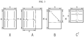
- FIG. 3 is a diagram referenced in describing an exemplary observation matrix as a dataset indicating a voltage history of the battery cell shown in FIG. 2 .
- the control unit 142 may determine a voltage value of the cell voltage of each of the plurality of battery cells BC 1 ⁇ BC n at a predetermined time interval based on the voltage signal from the voltage measurement circuit 110, and record the determined voltage value in the memory 141.
- the preset time may be equal to a time length of a period for abnormality detection as described below.
- the control unit 142 determines an observation matrix X including a plurality of observation voltage vectors X 1 ⁇ X n over the specified period ⁇ t for the predetermined time in the past.
- a moving window 200 may be used to determine the observation matrix X.
- the plurality of observation voltage vectors X 1 ⁇ X n indicates a time-dependent change in the cell voltage of each of the plurality of battery cells BC 1 ⁇ BC n measured at the preset time interval within the moving window 200.
- the moving window 200 is used to set the period ⁇ t during which the plurality of observation voltage vectors X 1 ⁇ X n is obtained with the movement of the moving window 200 by the preset time interval at the preset time interval.
- the size ⁇ t of the moving window 200 may be preset or adjustable by the control unit 142.
- a curve 210 exemplarily indicates a time-dependent change in the cell voltage of the k th battery cell BC k among the plurality of battery cells BC 1 ⁇ BC n .
- the abnormal state may be a state that triggers an abnormal behavior of the cell voltage, for example, an internal short circuit.
- t 1 and t m are the starting time and the ending time of the specified period ⁇ t, respectively
- t i is a time point corresponding to a time index i within the specified period ⁇ t.
- k is a natural number of n or smaller, and may indicate a cell index used to distinguish the plurality of battery cells BC 1 ⁇ BC n .
- the abnormality detection operation according to the present disclosure will be described on the basis of the k th battery cell BC k .
- the description of the k th battery cell BC k may be applied in common to the remaining battery cells BC of the plurality of battery cells BC 1 ⁇ BC n .
- the observation matrix X is an m ⁇ n matrix including m rows and n columns.
- m is a natural number that is larger than n
- i is a natural number of 1 or greater and m or smaller
- j is a natural number of 1 or greater and n or smaller
- k is a natural number of less than n.
- the n column vectors of the observation matrix X may correspond to the plurality of observation voltage vectors X 1 ⁇ X n in a one-to-one relationship. That is, each of the plurality of observation voltage vectors X 1 ⁇ X n is a column vector of the observation matrix X, and includes m elements (the measured cell voltages).
- the k th observation voltage vector X k is a time-series array of the cell voltage of the k th battery cell BC k measured m times, i.e., a time-series (set) of the measured cell voltages x 1k ⁇ x mk of the k th battery cell BC k .
- the k th observation voltage vector X k may be the k th column vector of the observation matrix X.
- 'x ik ' is an element (referred to as 'data' or 'component') indicating the i th measured cell voltage among the cell voltages of the k th battery cell BC j measured a total of m times within the specific period ⁇ t.
- the control unit 142 may extract a first sub-matrix A, a second sub-matrix B and a third sub-matrix C T from the observation matrix X by applying matrix decomposition to the observation matrix X. That is, the observation matrix X may be decomposed into the first sub-matrix A, the second sub-matrix B and the third sub-matrix C T .
- An algorithm used in the matrix decomposition may include, for example, Singular Value Decomposition (SVD) and Principal Component Analysis (PCA).
- SVD Singular Value Decomposition
- PCA Principal Component Analysis
- the superscript 'T' on the right side of the matrix indicates a transposed matrix. As shown, the product of multiplying the first sub-matrix A, the second sub-matrix B and the third sub-matrix C T is equal to the observation matrix X.
- the first sub-matrix A is an m ⁇ m matrix.
- the second sub-matrix B is an m ⁇ n matrix.
- the third sub-matrix C T is an n ⁇ n matrix.
- the first sub-matrix A is an orthogonal matrix, and includes a plurality of principal component vectors A 1 ⁇ A m .
- Each principal component vector of the plurality of principal component vectors A 1 ⁇ A m may be referred to as a 'left singular vector'.
- Each principal component vector includes m elements, and may be a column vector of the first sub-matrix A. That is, the first sub-matrix A may be expressed below.
- A A 1 A 2 ... A m
- a i a 1i a 2 i ... a mi T
- the principal component vectors A 1 ⁇ A n indicate variance information of the observation matrix X.
- the j th principal component vector A j corresponds to an axial direction in which the variance of elements of the observation matrix X is the j th largest one. That is, when the elements of the observation matrix X are mapped to the axis of each of the plurality of principal component vectors A 1 ⁇ A m once, the variance of the elements of the observation matrix X along the axis of the j th principal component vector A j may be the j th largest.
- the j th principal component vector A j As the variance of the j th principal component vector A j is larger, it indicates that the j th principal component vector A j has a larger descriptive factor for a distribution of elements of the observation matrix X. As the descriptive factor of the j th principal component vector A j increases, the j th principal component vector A j contains a larger amount of information associated with the common voltage behavior characteristics (for example, a tendency of normal voltage behavior) of the plurality of battery cells BC 1 ⁇ BC n within the moving window 200.
- the common voltage behavior characteristics for example, a tendency of normal voltage behavior
- the descriptive factor of the j th principal component vector A j is lower, i.e., the j th principal component vector A j contains a larger amount of information associated with noisy characteristics (for example, abnormal state).
- the second sub-matrix B is a diagonal matrix, and includes a plurality of singular values b 11 ⁇ b nn as elements of a principal diagonal. That is, the second sub-matrix B may be expressed below.
- B B 1 B 2 ... B n
- B j b 1j b 2j ... b mj T
- b ij is 0.
- b jj is the j th singular value.
- the principal component vectors A n+1 ⁇ A m may be redundant in the description of the variance information of the observation vector X.
- the plurality of singular values b 11 ⁇ b nn may satisfy the following relationship. b 11 ⁇ b 22 ⁇ ... ⁇ b nn ⁇ 0.
- the plurality of singular values b 11 ⁇ b nn may be referred to as first to n th singular values in the descending order of size, and b jj may be the j th largest singular value among the plurality of singular values b 11 ⁇ b nn .
- the plurality of singular values b 11 ⁇ b nn indicates descriptive factor information of the plurality of principal component vectors A 1 ⁇ A n .
- the singular value b jj of the second sub-matrix B indicates the descriptive factor of the j th principal component vector A j .
- the first to n th principal component vectors A 1 ⁇ A n , the first to n th singular values b 11 ⁇ b nn and the first to n th coefficient vectors C 1 T ⁇ C n T may correspond to one another in a one-to-one relationship.
- Equation 1 A j is treated as a (m ⁇ 1) matrix, and C j T is treated as a (1 ⁇ n) matrix.
- the k th observation voltage vector X k is equal to the sum of first to n th partial voltage vectors that depend on the first to n th principal component vectors A 1 ⁇ A n in a one-to-one relationship, and may satisfy the relationship by the following Equation 2.
- the j th partial voltage vector Y kj of the k th observation voltage vector X k is a voltage component of the k th observation voltage vector X k that depends on the j th principal component vector A j , and may be equal to the multiplication of the j th principal component vector A j , the j th singular value b jj and the coefficient c jk .
- the control unit 142 may increase the size of the moving window 200 by a predetermined time in the next cycle.
- the reason of increasing the size of the moving window 200 is to sufficiently reflect the common voltage behavior characteristics of the plurality of battery cells BC 1 ⁇ BC n in the observation vectors X.
- FIG. 4 is a graph exemplarily showing the coefficient vector.
- the horizontal axis indicates the cell index corresponding to each coefficient of the j th coefficient vector C j T
- the vertical axis indicates the size of each coefficient.
- the control unit 142 may determine each coefficient having an absolute value of difference between the coefficient and the average c j_av larger than the first reference value R j1 among the first to n th coefficients c j1 ⁇ c jn as the invalid coefficient of the j th coefficient vector C j T .
- FIG. 4 shows that the coefficient c jk is smaller than the average c j_av by more than the first reference value R j1 . Accordingly, the control unit 142 may determine the coefficient c jk as the invalid coefficient of the j th coefficient vector C j T .
- FIG. 5 is a diagram reference in describing the relationship between the invalid coefficient and the partial voltage vector.
- FIG. 5 is a graph exemplarily showing the j th partial voltage vector Y kj of the k th observation voltage vector X k corresponding to the invalid coefficient c jk of FIG. 4 .
- the j th partial voltage vector Y kj is an (m ⁇ 1) matrix.
- the horizontal axis indicates the time index within the moving window 200
- the vertical axis indicates the partial voltage.
- the control unit 142 may determine a voltage characteristic value of the partial voltage vector Y kj based on m partial voltages included in the partial voltage vector Y kj .
- the voltage characteristic value may be a parameter indicating the influence (occupancy rate) of the partial voltage vector Y kj on the k th observation voltage vector X k .
- a large rate and/or slope of the voltage change exhibited by the partial voltage vector Y kj may indicate that the abnormal voltage behavior associated with the invalid coefficient c jk is greatly reflected in the k th observation voltage vector X k .
- control unit 142 may determine the voltage characteristic value to be equal to a difference ⁇ y kj between the maximum partial voltage y kj_max and the minimum partial voltage y kj_min among the m partial voltages of the partial voltage vector Y kj .
- control unit 142 may determine the voltage characteristic value to be equal to a slope between the maximum partial voltage y kj_max and the minimum partial voltage y kj_min .
- the control unit 142 may detect the k th battery cell BC k corresponding to the invalid coefficient c jk as faulty.
- the control unit 142 may determine the second reference value based on the voltage resolution of the voltage measurement circuit 110. For example, the control unit 142 may determine the second reference value to be equal to multiplication of the voltage resolution and a second scaling factor.
- the second scaling factor may be pre-recorded in the memory.
- the second reference value may be preset to, for example, 10.0 mV, considering the voltage resolution.
- the second reference value is for preventing the likelihood that a normal battery cell is wrongly detected as a faulty battery cell due to a measurement error of the cell voltage measured by the voltage measurement circuit 110.
- the voltage characteristic value ⁇ y kj is larger than the second reference value, the k th battery cell BC k may be determined to be faulty.
- FIG. 6 is a flowchart exemplarily showing a battery diagnosis method according to a first embodiment of the present disclosure. The method of FIG. 6 may be repeated at a preset time interval.
- the control unit 142 determines an observation matrix X including ae plurality of observation voltage vectors X 1 ⁇ X n corresponding to a plurality of battery cells BC 1 -BC n in a one-to-one relationship.
- the plurality of observation voltage vectors X 1 ⁇ X n indicates a time series of cell voltage of each of the plurality of battery cells BC 1 -BC n measured multiple times m in time series within the moving window 200.
- step S620 the control unit 142 determines a plurality of principal component vectors A 1 ⁇ A n , a plurality of singular values b 11 ⁇ b nn and a plurality of coefficient vectors C 1 T ⁇ C n T from the observation matrix X (see Equation 1).
- step S640 the control unit 142 determines whether at least one of the plurality of coefficients c j1 ⁇ c jn is larger than the first reference value R j1 .
- a value of the step S640 is "No”
- the method may end.
- the value of the step S640 is "Yes”
- the method performs step S650.
- step S670 the control unit 142 determines a voltage characteristic value ⁇ y kj of the partial voltage vector Y kj .
- step S680 the control unit 142 determines whether the voltage characteristic value ⁇ y kj is larger than a second reference value. When a value of the step S680 is "No", the method may end. The value of the step S680 being "Yes” indicates that the battery cell BC k corresponding to the invalid coefficient c jk is detected as faulty. When the value of the step S680 is "Yes”, the method performs step S690.
- FIG. 7 is a flowchart exemplarily showing a battery diagnosis method according to a second embodiment of the present disclosure. The method of FIG. 7 may be repeated at a preset time interval.
- steps S710 to S790 are the same as the steps S610 to S690 of FIG. 6 , and the repeated description is omitted.
- the method of FIG. 7 further including steps S722 and S724 is different from the method of FIG. 6 .
- the remote controller 240 may act as the battery diagnosis device. That is, the description of each of the control unit 142 and the memory 141 may be in common to the control unit 242 and the memory 241.
- the battery management system 100 may transmit data indicating the plurality of observation voltage vectors X 1 ⁇ X n the communication circuit 243 of the remote controller 240 through the interface unit 150.
Landscapes
- Physics & Mathematics (AREA)
- General Physics & Mathematics (AREA)
- Secondary Cells (AREA)
- Charge And Discharge Circuits For Batteries Or The Like (AREA)
- Tests Of Electric Status Of Batteries (AREA)
Abstract
Description
- The present disclosure relates to technology for battery cell abnormality detection.
- The present application claims the benefit of
Korean Patent Application No. 10-2020-0096786 filed on August 3, 2020 - Recently, there has been a rapid increase in the demand for portable electronic products such as laptop computers, video cameras and mobile phones, and with the extensive development of electric vehicles, accumulators for energy storage, robots and satellites, many studies are being made on high performance batteries that can be repeatedly recharged.
- Currently, commercially available batteries include nickel-cadmium batteries, nickel-hydrogen batteries, nickel-zinc batteries, lithium batteries and the like, and among them, lithium batteries have little or no memory effect, and thus they are gaining more attention than nickel-based batteries for their advantages that recharging can be done whenever it is convenient, the self-discharge rate is very low and the energy density is high.
- Recently, with the widespread of applications requiring high voltage, a battery pack including a plurality of battery cells connected in series is being widely used. As the number of battery cells included in the battery pack increases, there is an increasing likelihood that an abnormality of the battery cell occurs. Accordingly, there is an increasing need for diagnosis technology for accurately detecting an abnormality of the battery cell.
- The related art monitors cell information (for example, voltage, current, temperature) including a plurality of parameters associated with a state of the battery cell, and detects an abnormality of the battery cell based on the operational state (for example, charge, discharge, rest) of the battery cell and the monitored cell information.
- However, the above-described abnormality detection method requires a battery management system (BMS) to monitor the cell information of the battery cell using many sensors, so abnormality detection requires a large amount of computation and a long time. In particular, under the structure in which the power of the BMS is supplied from the battery cell, the electrical energy of the battery cell may be consumed all the time during the operation of the BMS for abnormality detection.
- Moreover, the related art detects abnormality of the battery cell based on the rapid changes in the cell information of the battery cell in a short time. However, in some instances, the cell information of the faulty battery cell does not always rapidly change in a short time, and may tend to slowly change over a long period of time, failing to detect an abnormality of the battery cell at a proper time.
- The present disclosure is designed to solve the above-described problem, and therefore the present disclosure is directed to providing a battery diagnosis device, a battery pack, a battery system and a battery diagnosis method using a cell voltage of each of a plurality of battery cells connected in series as a single parameter for abnormality detection.
- The present disclosure is further directed to providing a battery diagnosis device, a battery pack, a battery system and a battery diagnosis method for battery cell abnormality detection, in which an observation matrix is generated, the observation matrix being a dataset including a plurality of observation voltage vectors indicating a voltage history (time-series) of a cell voltage of each of a plurality of battery cells observed during the same period, and an abnormal behavior of the cell voltage of each battery cell is identified based on a result of analyzing the observation matrix.
- These and other objects and advantages of the present disclosure may be understood by the following description and will be apparent from the embodiments of the present disclosure. In addition, it will be readily understood that the objects and advantages of the present disclosure may be realized by the means set forth in the appended claims and a combination thereof.
- A battery diagnosis device according to an aspect of the present disclosure includes a memory configured to store an observation matrix including a plurality of observation voltage vectors indicating a time-series of cell voltage of each of a plurality of battery cells, and a control unit configured to determine a plurality of principal component vectors, a plurality of singular values and a plurality of coefficient vectors from the observation matrix. Each coefficient vector includes a plurality of coefficients corresponding to the plurality of observation voltage vectors in a one-to-one relationship. The control unit is configured to, for each coefficient vector, determine an invalid coefficient among the plurality of coefficients by comparing the plurality of coefficients included in the corresponding coefficient vector, and detect abnormality of the battery cell corresponding to the invalid coefficient among the plurality of battery cells based on the principal component vector corresponding to the corresponding coefficient vector among the plurality of principal component vectors, the singular value corresponding to the corresponding coefficient vector among the plurality of singular values and the invalid coefficient.
- The control unit may be configured to determine a first sub-matrix, a second sub-matrix and a third sub-matrix by applying a matrix decomposition algorithm to the observation matrix. The first sub-matrix includes the plurality of principal component vectors as column vectors. The second sub-matrix includes the plurality of singular values as elements of a principal diagonal. The third sub-matrix includes the plurality of coefficient vectors as row vectors.
- The control unit may be configured to determine, as the invalid coefficient, the coefficient of which an absolute value of a difference between the coefficient and an average of the plurality of coefficients among the plurality of coefficients is larger than a first reference value.
- The control unit may be configured to determine the first reference value to be equal to a value obtained by multiplying a standard deviation of the plurality of coefficients by a first scaling factor.
- The control unit may be configured to, for each coefficient vector, extract a partial voltage vector of the observation voltage vector corresponding to the invalid coefficient among the plurality of observation voltage vectors by multiplying the principal component vector corresponding to the corresponding coefficient vector among the plurality of principal component vectors, the singular value corresponding to the corresponding coefficient vector among the plurality of singular values and the invalid coefficient, and detect the battery cell corresponding to the invalid coefficient among the plurality of battery cells as faulty when a voltage characteristic value of the partial voltage vector is larger than a second reference value.
- The control unit may be configured to determine the voltage characteristic value to be equal to a difference between a maximum partial voltage and a minimum partial voltage among a plurality of partial voltages included in the partial voltage vector.
- The control unit may be configured to determine the second reference value to be equal to a value obtained by multiplying a voltage resolution of a voltage measurement circuit by a second scaling factor.
- The control unit may be configured to output a fault message when a ratio of a maximum singular value to a minimum singular value among the plurality of singular values is less than a preset value.
- A battery pack according to another aspect of the present disclosure includes the battery diagnosis device.
- A battery system according to still another aspect of the present disclosure includes the battery pack.
- A battery diagnosis method according to yet another aspect of the present disclosure includes determining a plurality of principal component vectors, a plurality of singular values and a plurality of coefficient vectors from an observation matrix including a plurality of observation voltage vectors indicating a time series of cell voltage of each of a plurality of battery cells. Each coefficient vector includes a plurality of coefficients corresponding to the plurality of observation voltage vectors in a one-to-one relationship. The battery diagnosis method further includes, for each coefficient vector, determining an invalid coefficient among the plurality of coefficients by comparing the plurality of coefficients included in the corresponding coefficient vector, and detecting abnormality of the battery cell corresponding to the invalid coefficient among the plurality of battery cells based on the principal component vector corresponding to the corresponding coefficient vector among the plurality of principal component vectors, the singular value corresponding to the corresponding coefficient vector among the plurality of singular values and the invalid coefficient.
- Determining the invalid coefficient among the plurality of coefficients may include determining, as the invalid coefficient, the coefficient of which an absolute value of a difference between the coefficient and an average of the plurality of coefficients among the plurality of coefficients is larger than a first reference value.
- Detecting abnormality of the battery cell corresponding to the invalid coefficient among the plurality of battery cells may include extracting a partial voltage vector of the observation voltage vector corresponding to the invalid coefficient among the plurality of observation voltage vectors by multiplying the principal component vector corresponding to the corresponding coefficient vector among the plurality of principal component vectors, the singular value corresponding to the corresponding coefficient vector among the plurality of singular values and the invalid coefficient, and detecting the battery cell corresponding to the invalid coefficient among the plurality of battery cells as faulty when a voltage characteristic value of the partial voltage vector is larger than a second reference value.
- According to at least one of the embodiments of the present disclosure, it is possible to reduce the computational amount, time and power required for abnormality detection by using only the cell voltage except the current or temperature to detect abnormality of each of a plurality of battery cells connected in series.
- In addition, according to at least one of the embodiments of the present disclosure, it is possible to improve the accuracy of battery cell abnormality detection by generating an observation matrix which is a dataset including a plurality of observation voltage vectors indicating a voltage history (time-series) of a cell voltage of each of a plurality of battery cells observed for the same period of time, and identifying an abnormal behavior of the cell voltage of each battery cell based on a result of analyzing the observation matrix.
- The effects of the present disclosure are not limited to the effects mentioned above, and these and other effects will be clearly understood by those skilled in the art from the appended claims.
- The accompanying drawings illustrate a preferred embodiment of the present disclosure, and together with the detailed description of the present disclosure described below, serve to provide a further understanding of the technical aspects of the present disclosure, and thus the present disclosure should not be construed as being limited to the drawings.
-
FIG. 1 is a diagram exemplarily showing a configuration of a battery system according to the present disclosure. -
FIG. 2 is a graph exemplarily showing a change in cell voltage of a battery cell over time. -
FIG. 3 is a diagram referenced in describing an exemplary observation matrix as a dataset indicating a voltage history of the battery cell shown inFIG. 2 . -
FIG. 4 is a graph exemplarily showing a coefficient vector. -
FIG. 5 is a diagram referenced in describing a relationship between an invalid coefficient and a partial voltage vector. -
FIG. 6 is a flowchart exemplarily showing a battery diagnosis method according to a first embodiment of the present disclosure. -
FIG. 7 is a flowchart exemplarily showing a battery diagnosis method according to a second embodiment of the present disclosure. - Hereinafter, the preferred embodiments of the present disclosure will be described in detail with reference to the accompanying drawings. Prior to the description, it should be understood that the terms or words used in the specification and the appended claims should not be construed as being limited to general and dictionary meanings, but rather interpreted based on the meanings and concepts corresponding to the technical aspects of the present disclosure on the basis of the principle that the inventor is allowed to define the terms appropriately for the best explanation.
- Therefore, the embodiments described herein and illustrations shown in the drawings are just a most preferred embodiment of the present disclosure, but not intended to fully describe the technical aspects of the present disclosure, so it should be understood that a variety of other equivalents and modifications could have been made thereto at the time that the application was filed.
- The terms including the ordinal number such as "first", "second" and the like, are used to distinguish one element from another among various elements, but not intended to limit the elements by the terms.
- Unless the context clearly indicates otherwise, it will be understood that the term "comprises" when used in this specification, specifies the presence of stated elements, but does not preclude the presence or addition of one or more other elements. Additionally, the term "control unit" as used herein refers to a processing unit of at least one function or operation, and this may be implemented by hardware and software either alone or in combination.
- In addition, throughout the specification, it will be further understood that when an element is referred to as being "connected to" another element, it can be directly connected to the other element or intervening elements may be present.
-
FIG. 1 is a diagram exemplarily showing a configuration of a battery system according to the present disclosure. -
FIG. 1 shows an energy storage system as an example of thebattery system 1. Referring toFIG. 1 , thebattery system 1 includes abattery pack 10 and aswitch 20. Thebattery system 1 may further include at least one of aremote controller 240 or apower conversion system 30. Thebattery system 1 is not limited to the energy storage system, and may include any battery system having a charging function and/or a discharging function of thebattery pack 10 provided therein, such as an electric vehicle or a battery tester. - The
battery pack 10 includes a positive terminal P+, a negative terminal P-, acell group 11 and abattery management system 100. Thecell group 11 includes a plurality of battery cells BC1∼BCn (n is a natural number of 2 or greater) electrically connected between the positive terminal P+ and the negative terminal P-.FIG. 1 shows the plurality of battery cells BC1~BCn connected in series within thecell group 11. Hereinafter, in providing the description in common to the plurality of battery cells BC1~BCn, the reference sign 'BC' is used to refer to the battery cell. - The positive terminal and the negative terminal of the battery cell BC are electrically coupled to other battery cell BC through a conductor such as a busbar. The battery cell BC may be a lithium ion battery cell. The battery cell BC is not limited to a particular type, and may include any type of battery cell that can be repeatedly recharged.
- The
switch 20 is installed on a power line PL for thebattery pack 10. While theswitch 20 is on, power transfer from any one of thebattery pack 10 or thepower conversion system 30 to the other is possible. Theswitch 20 may be implemented as at least one of well-known switching devices such as a relay and a Field Effect Transistor (FET). - The
power conversion system 30 is operably coupled to at least one of thebattery management system 100 or theremote controller 240. Operably coupled refers to directly/indirectly connected to transmit and receive a signal in one or two directions. Thepower conversion system 30 may produce the direct current power for the charge of thecell group 11 from the alternating current power supplied by anelectrical grid 40. Thepower conversion system 30 may produce the alternating current power from the direct current power from thebattery pack 10. - The
battery management system 100 may include avoltage measurement circuit 110 and abattery controller 140. Thebattery management system 100 may further include at least one of acurrent sensor 120, atemperature sensor 130 or aninterface unit 150. Theinterface unit 150 may be included in thebattery controller 140. - The
voltage measurement circuit 110 is provided to be electrically connectable to the positive terminal and the negative terminal of the battery cell BC. Thevoltage measurement circuit 110 may measure a cell voltage or a voltage across the battery cell BC, and output a signal indicating the measured cell voltage to thebattery controller 140. - The
current sensor 120 is electrically connected in series to thecell group 11 through the power line PL. For example, a shunt resistor or a hall effect device may be used as thecurrent sensor 120. Thecurrent sensor 120 may measure a current flowing through thecell group 11, and output a signal indicating the measured current to thebattery controller 140. - The
temperature sensor 130 is disposed within a predetermined distance range from thecell group 11. For example, a thermocouple may be used as thetemperature sensor 130. Thetemperature sensor 130 may measure a temperature of thecell group 11, and output a signal indicating the measured temperature to thebattery controller 140. - The
battery controller 140 is operably coupled to thevoltage measurement circuit 110, thecurrent sensor 120, thetemperature sensor 130 and/or theinterface unit 150. At least one of thebattery controller 140 or theremote controller 240 may control the on/off of theswitch 20 according to the result of diagnosis for thecell group 11. - The
interface unit 150 may be coupled to theremote controller 240 of thebattery system 1 to enable communication. Theinterface unit 150 may transmit a signal from theremote controller 240 to thebattery controller 140, and a signal from thebattery controller 140 to theremote controller 240. The signal from thebattery controller 140 may include information for notifying abnormality of the battery cell BC. The communication between theinterface unit 150 and theremote controller 240 may use, for example, a wired network such as a local area network (LAN), a controller area network (CAN) and a daisy chain and/or a wireless network such as Bluetooth, Zigbee and Wi-Fi. Theinterface unit 150 may include an output device (for example, a display, a speaker) to provide the information received from thebattery controller 140 and/or theremote controller 240 in a recognizable format. Theremote controller 240 may control at least one of thebattery pack 10, theswitch 20 or thepower conversion system 30 based on cell information (for example, cell voltage, current, temperature, SOC, abnormality of the battery cell BC) collected through communication with thebattery management system 100. - The
battery controller 140 includes amemory 141 and acontrol unit 142. Theremote controller 240 may include amemory 241 and acontrol unit 242. Theremote controller 240 may further include acommunication circuit 243. Theremote controller 240 may be implemented in the form of a cloud server or a mobile diagnosis device. Thecommunication circuit 243 is for wired/wireless communication with thebattery management system 100. - Each of the
control unit 142 and thecontrol unit 242 may be implemented in hardware using at least one of application specific integrated circuits (ASICs), digital signal processors (DSPs), digital signal processing devices (DSPDs), programmable logic devices (PLDs), field programmable gate arrays (FPGAs), microprocessors or electrical units for performing the other functions. - At least one of the
memory 141 or thememory 142 may pre-store programs and data necessary to perform battery diagnosis methods (diagnosis procedures) according to embodiments as described below. Each of thememory 141 and thememory 142 may include, for example, at least one type of storage medium of flash memory type, hard disk type, Solid State Disk (SSD) type, Silicon Disk Drive (SDD) type, multimedia card micro type, random access memory (RAM), static random access memory (SRAM), read-only memory (ROM), electrically erasable programmable read-only memory (EEPROM) or programmable read-only memory (PROM). At least one of thememory 141 or thememory 142 may record data and algorithms required to detect abnormality of the battery BC by performing the following diagnosis procedures (FIGS. 2 to 6 ). Thememory 141 and thecontrol unit 142 may be integrated into a single chip. Thememory 241 and thecontrol unit 242 may be integrated into a single chip. - The
battery controller 140 is an example of a battery diagnosis device according to the present disclosure, and theremote controller 240 is another example of a battery diagnosis device according to the present disclosure. That is, the diagnosis procedures described below with reference toFIGS. 2 to 7 are performed by at least one of thebattery controller 140 or theremote controller 240 provided as a battery diagnosis device. - The battery diagnosis device according to the present disclosure may perform the diagnosis procedures (see
FIGS. 6 and7 ) for detecting abnormality of the plurality of battery cells BC1~BCn. The diagnosis procedures may be based on voltage data (see X1~Xn inFIG. 2 ) acquired for a specified period (for example, a predetermined time in the past) during which thecell group 11 is kept in a predetermined diagnosis possible state (for example, rest, constant current charge, constant voltage charge, constant current discharge). The following description will be made under the assumption that thebattery controller 140 is provided as a battery diagnosis device. -
FIG. 2 is a graph exemplarily showing a change in cell voltage of the battery cell over time, andFIG. 3 is a diagram referenced in describing an exemplary observation matrix as a dataset indicating a voltage history of the battery cell shown inFIG. 2 . - The
control unit 142 may determine a voltage value of the cell voltage of each of the plurality of battery cells BC1∼BCn at a predetermined time interval based on the voltage signal from thevoltage measurement circuit 110, and record the determined voltage value in thememory 141. The preset time may be equal to a time length of a period for abnormality detection as described below. - The
control unit 142 determines an observation matrix X including a plurality of observation voltage vectors X1~Xn over the specified period Δt for the predetermined time in the past. A movingwindow 200 may be used to determine the observation matrix X. For example, the plurality of observation voltage vectors X1~Xn indicates a time-dependent change in the cell voltage of each of the plurality of battery cells BC1∼BCn measured at the preset time interval within the movingwindow 200. The movingwindow 200 is used to set the period Δt during which the plurality of observation voltage vectors X1~Xn is obtained with the movement of the movingwindow 200 by the preset time interval at the preset time interval. The size Δt of the movingwindow 200 may be preset or adjustable by thecontrol unit 142. - The cell voltage of the battery cell BC may be measured by the
voltage measurement circuit 110 multiple times (for example, a total of m, m is a natural number of 2 or greater) in time series, and the measured cell voltages may be recorded in thememory 141 by thecontrol unit 142. For example, where the size of the movingwindow 200 = 200 sec and the preset time = 1 sec, m=200, and thus the cell voltage of the battery cell BC is measured 200 times within the movingwindow 200. - Referring to
FIG. 2 , acurve 210 exemplarily indicates a time-dependent change in the cell voltage of the kth battery cell BCk among the plurality of battery cells BC1~BCn. The abnormal state may be a state that triggers an abnormal behavior of the cell voltage, for example, an internal short circuit. InFIG. 2 , t1 and tm are the starting time and the ending time of the specified period Δt, respectively, and ti is a time point corresponding to a time index i within the specified period Δt. In the kth battery cell BCk, k is a natural number of n or smaller, and may indicate a cell index used to distinguish the plurality of battery cells BC1~BCn. - Hereinafter, the abnormality detection operation according to the present disclosure will be described on the basis of the kth battery cell BCk. The description of the kth battery cell BCk may be applied in common to the remaining battery cells BC of the plurality of battery cells BC1~BCn.
- Referring to
FIG. 3 , the observation matrix X is an m×n matrix including m rows and n columns. Hereinafter, for convenience of description, assume that m is a natural number that is larger than n, i is a natural number of 1 or greater and m or smaller, j is a natural number of 1 or greater and n or smaller, and k is a natural number of less than n. - The n column vectors of the observation matrix X may correspond to the plurality of observation voltage vectors X1~Xn in a one-to-one relationship. That is, each of the plurality of observation voltage vectors X1~Xn is a column vector of the observation matrix X, and includes m elements (the measured cell voltages). The kth observation voltage vector Xk is a time-series array of the cell voltage of the kth battery cell BCk measured m times, i.e., a time-series (set) of the measured cell voltages x1k ~ xmk of the kth battery cell BCk. The kth observation voltage vector Xk may be the kth column vector of the observation matrix X. Referring to
FIG. 2 , in the observation matrix X, 'xik' is an element (referred to as 'data' or 'component') indicating the ith measured cell voltage among the cell voltages of the kth battery cell BCj measured a total of m times within the specific period Δt. - The
control unit 142 may extract a first sub-matrix A, a second sub-matrix B and a third sub-matrix CT from the observation matrix X by applying matrix decomposition to the observation matrix X. That is, the observation matrix X may be decomposed into the first sub-matrix A, the second sub-matrix B and the third sub-matrix CT. An algorithm used in the matrix decomposition may include, for example, Singular Value Decomposition (SVD) and Principal Component Analysis (PCA). In the specification, the superscript 'T' on the right side of the matrix indicates a transposed matrix. As shown, the product of multiplying the first sub-matrix A, the second sub-matrix B and the third sub-matrix CT is equal to the observation matrix X. - The first sub-matrix A is an m×m matrix. The second sub-matrix B is an m×n matrix. The third sub-matrix CT is an n×n matrix.
- The first sub-matrix A is an orthogonal matrix, and includes a plurality of principal component vectors A1~Am. Each principal component vector of the plurality of principal component vectors A1~Am may be referred to as a 'left singular vector'. Each principal component vector includes m elements, and may be a column vector of the first sub-matrix A. That is, the first sub-matrix A may be expressed below.


- Among the plurality of principal component vectors A1~Am, the principal component vectors A1~An indicate variance information of the observation matrix X. The jth principal component vector Aj corresponds to an axial direction in which the variance of elements of the observation matrix X is the jth largest one. That is, when the elements of the observation matrix X are mapped to the axis of each of the plurality of principal component vectors A1~Am once, the variance of the elements of the observation matrix X along the axis of the jth principal component vector Aj may be the jth largest.
- As the variance of the jth principal component vector Aj is larger, it indicates that the jth principal component vector Aj has a larger descriptive factor for a distribution of elements of the observation matrix X. As the descriptive factor of the jth principal component vector Aj increases, the jth principal component vector Aj contains a larger amount of information associated with the common voltage behavior characteristics (for example, a tendency of normal voltage behavior) of the plurality of battery cells BC1∼BCn within the moving
window 200. On the contrary, as the variance of the jth principal component vector Aj is smaller, the descriptive factor of the jth principal component vector Aj is lower, i.e., the jth principal component vector Aj contains a larger amount of information associated with noisy characteristics (for example, abnormal state). - The second sub-matrix B is a diagonal matrix, and includes a plurality of singular values b11~bnn as elements of a principal diagonal. That is, the second sub-matrix B may be expressed below.


- Where i≠j, bij is 0. bjj is the jth singular value.
- That is, among the total of m×n elements of the second sub-matrix B, the remaining elements except n elements b11~bnn of the principal diagonal are all 0. Accordingly, among the plurality of principal component vectors A1~Am, the principal component vectors An+1~Am may be redundant in the description of the variance information of the observation vector X.
- The plurality of singular values b11~bnn may satisfy the following relationship. b11≥b22≥ ... ≥ bnn≥ 0. The plurality of singular values b11~bnn may be referred to as first to nth singular values in the descending order of size, and bjj may be the jth largest singular value among the plurality of singular values b11~bnn.
- The plurality of singular values b11~bnn indicates descriptive factor information of the plurality of principal component vectors A1~An. The singular value bjj of the second sub-matrix B indicates the descriptive factor of the jth principal component vector Aj.
- The third sub-matrix CT is an orthogonal matrix and includes a plurality of coefficient vectors C1 T~Cn T. Each coefficient vector of the plurality of coefficient vectors C1 T~Cn T may be referred to as a 'right singular vector'. Each coefficient vector includes n components, and may be a row vector of the third sub-matrix CT. The third sub-matrix CT may be expressed below.


- The plurality of coefficient vectors C1 T~Cn T indicates dependency information of the plurality of observation voltage vectors X1~Xn on the plurality of principal component vectors A1~An. Specifically, how much each of the plurality of observation voltage vectors X1~Xn is affected by the jth principal component vector Aj is set by the jth coefficient vector Cj T. The jth coefficient vector Cj T includes a plurality of coefficients cj1~cjn corresponding to the first to nth observation voltage vectors X1~Xn in a one-to-one relationship. For example, cjk of the jth coefficient vector Cj T indicates the influence of the jth principal component vector Aj on the kth observation voltage vector Xk.
- The first to nth principal component vectors A1~An, the first to nth singular values b11~bnn and the first to nth coefficient vectors C1 T~Cn T may correspond to one another in a one-to-one relationship.
- The observation matrix X is equal to the multiplication of the first sub-matrix A, the second sub-matrix B and the third sub-matrix CT, and may satisfy the relationship by the following
Equation 1.
- In
Equation 1, Aj is treated as a (m×1) matrix, and Cj T is treated as a (1×n) matrix. - Referring to
Equation 1, the kth observation voltage vector Xk is equal to the sum of first to nth partial voltage vectors that depend on the first to nth principal component vectors A1~An in a one-to-one relationship, and may satisfy the relationship by the followingEquation 2.
- In
Equation 2, Ykj = (bjj × Aj × cjk) is the jth partial voltage vector of the kth observation voltage vector Xk. The jth partial voltage vector Ykj of the kth observation voltage vector Xk is a voltage component of the kth observation voltage vector Xk that depends on the jth principal component vector Aj, and may be equal to the multiplication of the jth principal component vector Aj, the jth singular value bjj and the coefficient cjk. That is, the jth partial voltage vector Ykj may be the result of recovering (approximating) the kth observation voltage vector Xk using only the jth principal component vector Aj among the first to nth principal component vectors A1~An. Accordingly, the jth partial voltage vector Ykj has m elements corresponding to m elements of the kth observation voltage vector Xk in a one-to-one relationship. The element of each partial voltage vector may be referred to as 'partial voltage (or approximation voltage)', and the partial voltage vector may be referred to as 'recovery voltage vector'. - The
control unit 142 may calculate a ratio of a maximum singular value bn to a minimum singular value bnn among the first to nth singular values b11~bnn prior to detecting abnormality of the first to nth battery cells BC1-BCn based on the first to nth principal component vectors A1~An, the first to nth singular values b11~bnn and the first to nth coefficient vectors C1 T~Cn T When the ratio of the maximum singular value bn to the minimum singular value bnn is less than a preset ratio (for example, 200%), thecontrol unit 142 may output a fault message indicating disabled abnormality detection of the battery cell BC. The disabled abnormality detection is a situation in which there is no explicit difference in descriptive factor between the plurality of principal component vectors A1~An. That is, in the disabled abnormality detection situation, none of the plurality of principal component vectors A1~An sufficiently includes information associated with the common voltage behavior characteristics of the plurality of battery cells BC1~BCn. The cause of the disabled abnormality detection may be, for example, malfunction of thevoltage measurement circuit 110 or abnormality in the number of battery cells BC exceeding a predetermined ratio (for example, 50%) among the first to nth battery cells BC1~BCn. - When the ratio of the maximum value bn to the minimum value bnn is less than the preset ratio, the
control unit 142 may increase the size of the movingwindow 200 by a predetermined time in the next cycle. The reason of increasing the size of the movingwindow 200 is to sufficiently reflect the common voltage behavior characteristics of the plurality of battery cells BC1~BCn in the observation vectors X. -
FIG. 4 is a graph exemplarily showing the coefficient vector. InFIG. 4 , the horizontal axis indicates the cell index corresponding to each coefficient of the jth coefficient vector Cj T, and the vertical axis indicates the size of each coefficient. For example, the cell index=1 corresponds to the first battery cell BC1. - The
control unit 142 determines whether there is an invalid coefficient in first to nth coefficients cj1~cjn included in the jth coefficient vector Cj T by comparing the first to nth coefficients cj1~cjn. The invalid coefficient of the jth coefficient vector Cj T indicates the degree of abnormal voltage behavior by the jth principal component vector Aj reflected in the voltage history of the specific battery cell corresponding to the corresponding invalid coefficient. The remaining coefficients except the invalid coefficient may be a valid coefficient. - Referring to
FIG. 4 , thecontrol unit 142 may determine an average cj_av and a standard deviation of the first to nth coefficients cj1~cjn included in the jth coefficient vector Cj T. Thecontrol unit 142 may determine a first reference value Rj1 based on the standard deviation of the first to nth coefficients cj1~cjn. For example, thecontrol unit 142 may determine the first reference value Rj1 to be equal to the multiplication of the standard deviation and a first scaling factor. The first scaling factor may be pre-recorded in thememory 141. - The
control unit 142 may determine each coefficient having an absolute value of difference between the coefficient and the average cj_av larger than the first reference value Rj1 among the first to nth coefficients cj1~cjn as the invalid coefficient of the jth coefficient vector Cj T.FIG. 4 shows that the coefficient cjk is smaller than the average cj_av by more than the first reference value Rj1. Accordingly, thecontrol unit 142 may determine the coefficient cjk as the invalid coefficient of the jth coefficient vector Cj T. -
FIG. 5 is a diagram reference in describing the relationship between the invalid coefficient and the partial voltage vector.FIG. 5 is a graph exemplarily showing the jth partial voltage vector Ykj of the kth observation voltage vector Xk corresponding to the invalid coefficient cjk ofFIG. 4 . In the same way as the kth observation voltage vector Xk, the jth partial voltage vector Ykj is an (m×1) matrix. InFIG. 5 , the horizontal axis indicates the time index within the movingwindow 200, and the vertical axis indicates the partial voltage. - Referring to
FIG. 5 , thecontrol unit 142 may determine a voltage characteristic value of the partial voltage vector Ykj based on m partial voltages included in the partial voltage vector Ykj. The voltage characteristic value may be a parameter indicating the influence (occupancy rate) of the partial voltage vector Ykj on the kth observation voltage vector Xk. Within the movingwindow 200, a large rate and/or slope of the voltage change exhibited by the partial voltage vector Ykj may indicate that the abnormal voltage behavior associated with the invalid coefficient cjk is greatly reflected in the kth observation voltage vector Xk. For example, thecontrol unit 142 may determine the voltage characteristic value to be equal to a difference Δykj between the maximum partial voltage ykj_max and the minimum partial voltage ykj_min among the m partial voltages of the partial voltage vector Ykj. Alternatively, thecontrol unit 142 may determine the voltage characteristic value to be equal to a slope between the maximum partial voltage ykj_max and the minimum partial voltage ykj_min. - When the voltage characteristic value of the partial voltage vector Ykj is larger than a second reference value, the
control unit 142 may detect the kth battery cell BCk corresponding to the invalid coefficient cjk as faulty. Thecontrol unit 142 may determine the second reference value based on the voltage resolution of thevoltage measurement circuit 110. For example, thecontrol unit 142 may determine the second reference value to be equal to multiplication of the voltage resolution and a second scaling factor. The second scaling factor may be pre-recorded in the memory. Alternatively, the second reference value may be preset to, for example, 10.0 mV, considering the voltage resolution. The second reference value is for preventing the likelihood that a normal battery cell is wrongly detected as a faulty battery cell due to a measurement error of the cell voltage measured by thevoltage measurement circuit 110. When the voltage characteristic value Δykj is larger than the second reference value, the kth battery cell BCk may be determined to be faulty. -
FIG. 6 is a flowchart exemplarily showing a battery diagnosis method according to a first embodiment of the present disclosure. The method ofFIG. 6 may be repeated at a preset time interval. - Referring to
FIGS. 1 to 6 , in step S610, thecontrol unit 142 determines an observation matrix X including ae plurality of observation voltage vectors X1~Xn corresponding to a plurality of battery cells BC1-BCn in a one-to-one relationship. The plurality of observation voltage vectors X1~Xn indicates a time series of cell voltage of each of the plurality of battery cells BC1-BCn measured multiple times m in time series within the movingwindow 200. - In step S620, the
control unit 142 determines a plurality of principal component vectors A1~An, a plurality of singular values b11~bnn and a plurality of coefficient vectors C1 T~Cn T from the observation matrix X (see Equation 1). - Steps S630 to S670 may be performed once for at least one of the plurality of coefficient vectors C1 T~Cn T For example, the steps S630 to S670 may be performed on a predetermined number of coefficient vectors corresponding to a predetermined number of singular values among the plurality of singular values b11~bnn in an ascending order. In another example, the steps S630 to S670 may be performed on the coefficient vector corresponding to each singular value of which a ratio to the sum of the plurality of singular values b11~bnn is equal to or less than a predetermined value.
- In the step S630, the
control unit 142 determines a first reference value Rj1 by comparing a plurality of coefficients cj1~cjn of the coefficient vector Cj T. Alternatively, the first reference value Rj1 may be a preset constant, and in this case, the step S630 may be omitted. - In step S640, the
control unit 142 determines whether at least one of the plurality of coefficients cj1~cjn is larger than the first reference value Rj1. When a value of the step S640 is "No", the method may end. When the value of the step S640 is "Yes", the method performs step S650. - In step S650, the
control unit 142 determines the coefficient cjk larger than the first reference value Rj1 among the plurality of coefficients cj1~cjn as an invalid coefficient of the coefficient vector Cj T. - In step S660, the
control unit 142 extracts a partial voltage vector Ykj of the observation voltage vector Xk corresponding to the invalid coefficient cjk based on the principal component vector Aj, the singular value bjj and the invalid coefficient cjk (see Equation 2). - In step S670, the
control unit 142 determines a voltage characteristic value Δykj of the partial voltage vector Ykj. - In step S680, the
control unit 142 determines whether the voltage characteristic value Δykj is larger than a second reference value. When a value of the step S680 is "No", the method may end. The value of the step S680 being "Yes" indicates that the battery cell BCk corresponding to the invalid coefficient cjk is detected as faulty. When the value of the step S680 is "Yes", the method performs step S690. - In step S690, the
control unit 142 activates a predetermined protection operation. For example, thecontrol unit 142 turns off theswitch 20. In another example, thecontrol unit 142 outputs a diagnosis message indicating information (for example, the cell index) of the battery cell BCk detected as faulty. The diagnosis message may be transmitted and received between thebattery controller 140 and theremote controller 240 through theinterface unit 150. Theinterface unit 150 may output visual and/or audible information corresponding to the diagnosis message. -
FIG. 7 is a flowchart exemplarily showing a battery diagnosis method according to a second embodiment of the present disclosure. The method ofFIG. 7 may be repeated at a preset time interval. - In the method of
FIG. 7 , steps S710 to S790 are the same as the steps S610 to S690 ofFIG. 6 , and the repeated description is omitted. - The method of
FIG. 7 further including steps S722 and S724 is different from the method ofFIG. 6 . - In step S722, the
control unit 142 determines whether a maximum ratio of the plurality of singular values b11~bnn is equal to or larger than a preset ratio. The maximum ratio is a ratio of a maximum value bn to a minimum value bnn among the plurality of singular values b11~bnn. A value of the step S722 being "No" indicates that there is no principal component vector having sufficiently large descriptive factor than the remaining principal component vectors among the plurality of principal component vectors A1~An. When the value of the step S722 is "No", the method performs step S724. When the value of the step S722 is "Yes", the method performs the step S730. - In step S724, the
control unit 142 outputs a fault message. The fault message indicates disabled abnormality detection. The fault message may be transmitted and received between thebattery controller 140 and theremote controller 240 through theinterface unit 150. Theinterface unit 150 may output visual and/or audible information corresponding to the fault message. - Although the description made above with reference to
FIGS. 2 to 7 is made under the assumption that thebattery controller 140 is provided as the battery diagnosis device, instead of thebattery controller 140, theremote controller 240 may act as the battery diagnosis device. That is, the description of each of thecontrol unit 142 and thememory 141 may be in common to thecontrol unit 242 and thememory 241. When theremote controller 240 is provided as the battery diagnosis device, thebattery management system 100 may transmit data indicating the plurality of observation voltage vectors X1~Xn thecommunication circuit 243 of theremote controller 240 through theinterface unit 150. - The embodiments of the present disclosure described hereinabove are not implemented only through the apparatus and method, and may be implemented through programs that perform functions corresponding to the configurations of the embodiments of the present disclosure or recording media having the programs recorded thereon, and such implementation may be easily achieved by those skilled in the art from the disclosure of the embodiments previously described.
- While the present disclosure has been hereinabove described with regard to a limited number of embodiments and drawings, the present disclosure is not limited thereto and it is obvious to those skilled in the art that various modifications and changes may be made thereto within the technical aspects of the present disclosure and the equivalent scope of the appended claims.
- Additionally, as many substitutions, modifications and changes may be made to the present disclosure described hereinabove by those skilled in the art without departing from the technical aspects of the present disclosure, the present disclosure is not limited by the above-described embodiments and the accompanying drawings, and some or all of the embodiments may be selectively combined to allow various modifications.
Claims (13)
- A battery diagnosis device, comprising:a memory configured to store an observation matrix including a plurality of observation voltage vectors indicating a time-series of cell voltage of each of a plurality of battery cells; anda control unit configured to determine a plurality of principal component vectors, a plurality of singular values and a plurality of coefficient vectors from the observation matrix,wherein each coefficient vector includes a plurality of coefficients corresponding to the plurality of observation voltage vectors in a one-to-one relationship, andwherein the control unit is configured to, for each coefficient vector,determine an invalid coefficient among the plurality of coefficients by comparing the plurality of coefficients included in the corresponding coefficient vector, anddetect abnormality of the battery cell corresponding to the invalid coefficient among the plurality of battery cells based on the principal component vector corresponding to the corresponding coefficient vector among the plurality of principal component vectors, the singular value corresponding to the corresponding coefficient vector among the plurality of singular values and the invalid coefficient.
- The battery diagnosis device according to claim 1, wherein the control unit is configured to determine a first sub-matrix, a second sub-matrix and a third sub-matrix by applying a matrix decomposition algorithm to the observation matrix,the first sub-matrix includes the plurality of principal component vectors as column vectors,the second sub-matrix includes the plurality of singular values as elements of a principal diagonal,the third sub-matrix includes the plurality of coefficient vectors as row vectors.
- The battery diagnosis device according to claim 1, wherein the control unit is configured to determine, as the invalid coefficient, the coefficient of which an absolute value of a difference between the coefficient and an average of the plurality of coefficients among the plurality of coefficients is larger than a first reference value.
- The battery diagnosis device according to claim 3, wherein the control unit is configured to determine the first reference value to be equal to a value obtained by multiplying a standard deviation of the plurality of coefficients by a first scaling factor.
- The battery diagnosis device according to claim 1, wherein the control unit is configured to, for each coefficient vector,extract a partial voltage vector of the observation voltage vector corresponding to the invalid coefficient among the plurality of observation voltage vectors by multiplying the principal component vector corresponding to the corresponding coefficient vector among the plurality of principal component vectors, the singular value corresponding to the corresponding coefficient vector among the plurality of singular values and the invalid coefficient, anddetect the battery cell corresponding to the invalid coefficient among the plurality of battery cells as faulty when a voltage characteristic value of the partial voltage vector is larger than a second reference value.
- The battery diagnosis device according to claim 5, wherein the control unit is configured to determine the voltage characteristic value to be equal to a difference between a maximum partial voltage and a minimum partial voltage among a plurality of partial voltages included in the partial voltage vector.
- The battery diagnosis device according to claim 5, wherein the control unit is configured to determine the second reference value to be equal to a value obtained by multiplying a voltage resolution of a voltage measurement circuit by a second scaling factor.
- The battery diagnosis device according to claim 1, wherein the control unit is configured to output a fault message when a ratio of a maximum singular value to a minimum singular value among the plurality of singular values is less than a preset value.
- A battery pack comprising the battery diagnosis device according to any one of claims 1 to 8.
- A battery system comprising the battery pack according to claim 9.
- A battery diagnosis method, comprising:determining a plurality of principal component vectors, a plurality of singular values and a plurality of coefficient vectors from an observation matrix including a plurality of observation voltage vectors indicating a time series of cell voltage of each of a plurality of battery cells,wherein each coefficient vector includes a plurality of coefficients corresponding to the plurality of observation voltage vectors in a one-to-one relationship, andwherein the battery diagnosis method further comprises, for each coefficient vector,determining an invalid coefficient among the plurality of coefficients by comparing the plurality of coefficients included in the corresponding coefficient vector; anddetecting abnormality of the battery cell corresponding to the invalid coefficient among the plurality of battery cells based on the principal component vector corresponding to the corresponding coefficient vector among the plurality of principal component vectors, the singular value corresponding to the corresponding coefficient vector among the plurality of singular values and the invalid coefficient.
- The battery diagnosis method according to claim 11, wherein determining the invalid coefficient among the plurality of coefficients comprises determining, as the invalid coefficient, the coefficient of which an absolute value of a difference between the coefficient and an average of the plurality of coefficients among the plurality of coefficients is larger than a first reference value.
- The battery diagnosis method according to claim 11, wherein detecting abnormality of the battery cell corresponding to the invalid coefficient among the plurality of battery cells comprises:extracting a partial voltage vector of the observation voltage vector corresponding to the invalid coefficient among the plurality of observation voltage vectors by multiplying the principal component vector corresponding to the corresponding coefficient vector among the plurality of principal component vectors, the singular value corresponding to the corresponding coefficient vector among the plurality of singular values and the invalid coefficient; anddetecting the battery cell corresponding to the invalid coefficient among the plurality of battery cells as faulty when a voltage characteristic value of the partial voltage vector is larger than a second reference value.
Applications Claiming Priority (2)
| Application Number | Priority Date | Filing Date | Title |
|---|---|---|---|
| KR20200096786 | 2020-08-03 | ||
| PCT/KR2021/010181 WO2022030971A1 (en) | 2020-08-03 | 2021-08-03 | Battery diagnosis device, battery pack, battery system, and battery diagnosis method |
Publications (3)
| Publication Number | Publication Date |
|---|---|
| EP4166963A1 true EP4166963A1 (en) | 2023-04-19 |
| EP4166963A4 EP4166963A4 (en) | 2023-11-29 |
| EP4166963B1 EP4166963B1 (en) | 2024-10-30 |
Family
ID=80118339
Family Applications (1)
| Application Number | Title | Priority Date | Filing Date |
|---|---|---|---|
| EP21854549.9A Active EP4166963B1 (en) | 2020-08-03 | 2021-08-03 | Battery diagnosis device, battery pack, battery system, and battery diagnosis method |
Country Status (9)
| Country | Link |
|---|---|
| US (1) | US20230184837A1 (en) |
| EP (1) | EP4166963B1 (en) |
| JP (1) | JP7389278B2 (en) |
| KR (2) | KR102861118B1 (en) |
| CN (1) | CN115769091B (en) |
| ES (1) | ES2998808T3 (en) |
| HU (1) | HUE068903T2 (en) |
| PL (1) | PL4166963T3 (en) |
| WO (1) | WO2022030971A1 (en) |
Families Citing this family (8)
| Publication number | Priority date | Publication date | Assignee | Title |
|---|---|---|---|---|
| CN116057394B (en) | 2020-10-05 | 2025-10-28 | 株式会社Lg新能源 | Apparatus and method for diagnosing battery status |
| KR102889127B1 (en) * | 2022-09-06 | 2025-11-19 | 주식회사 엘지에너지솔루션 | Electronic device for detecting abnormality of battery and operating method thereof |
| KR102881691B1 (en) * | 2022-09-06 | 2025-11-05 | 주식회사 엘지에너지솔루션 | Electronic device for detecting abnormality of battery and operating method thereof |
| KR20240043846A (en) * | 2022-09-27 | 2024-04-04 | 주식회사 엘지에너지솔루션 | Battery diagnosis apparatus, battery diagnosis method, battery pack, and vehicle including the same |
| KR20250083922A (en) * | 2023-12-01 | 2025-06-10 | 주식회사 엘지에너지솔루션 | Apparatus for managing battery and operating method of the same |
| WO2025234641A1 (en) * | 2024-05-08 | 2025-11-13 | 주식회사 엘지에너지솔루션 | Battery diagnosis device and battery diagnosis method thereof |
| CN118362932B (en) * | 2024-06-19 | 2024-09-13 | 广东奥博特实业有限公司 | Portable mobile power supply abnormal discharge detection method |
| CN119017939B (en) * | 2024-08-16 | 2025-05-06 | 国家市场监督管理总局缺陷产品召回技术中心 | Early identification method for battery system connection abnormality based on cloud operation data |
Family Cites Families (26)
| Publication number | Priority date | Publication date | Assignee | Title |
|---|---|---|---|---|
| US7113384B2 (en) * | 2000-01-27 | 2006-09-26 | Vssl Commercial, Inc. | Dynamic degaussing system |
| JP3539412B2 (en) * | 2001-08-09 | 2004-07-07 | 日産自動車株式会社 | Battery battery abnormality detection device |
| JP3714321B2 (en) * | 2002-11-25 | 2005-11-09 | 日産自動車株式会社 | Secondary battery charge rate estimation device |
| JP4547908B2 (en) * | 2003-12-25 | 2010-09-22 | 日産自動車株式会社 | Secondary battery input / output possible power estimation device |
| EP1709572A2 (en) * | 2004-01-13 | 2006-10-11 | New York University | Method, system, storage medium, and data structure for image recognition using multilinear independent component analysis |
| US7642786B2 (en) * | 2004-06-01 | 2010-01-05 | Midtronics, Inc. | Battery tester capable of identifying faulty battery post adapters |
| GB0428191D0 (en) * | 2004-12-23 | 2005-01-26 | Cambridge Display Tech Ltd | Digital signal processing methods and apparatus |
| JP5469813B2 (en) * | 2008-01-29 | 2014-04-16 | 株式会社日立製作所 | Battery system for vehicles |
| JP4816743B2 (en) * | 2009-02-17 | 2011-11-16 | ソニー株式会社 | Battery pack and detection method |
| JP5133926B2 (en) * | 2009-03-26 | 2013-01-30 | 株式会社日立製作所 | Battery system for vehicles |
| JP5722875B2 (en) * | 2009-04-10 | 2015-05-27 | ザ リージェンツ オブ ザ ユニバーシティ オブ ミシガン | Dynamically reconfigurable structure for large battery systems |
| US8330420B2 (en) * | 2009-04-10 | 2012-12-11 | The Regents Of The University Of Michigan | Dynamically reconfigurable framework for a large-scale battery system |
| JP2012036413A (en) * | 2010-08-03 | 2012-02-23 | Sony Corp | Hydrogen gas generating apparatus and its driving method, and power generation and hydrogen gas generating apparatus, and its driving method |
| JP2013081313A (en) * | 2011-10-04 | 2013-05-02 | Sanyo Electric Co Ltd | Charger |
| WO2014197883A1 (en) * | 2013-06-06 | 2014-12-11 | Transparent Technologies Inc. | Wireless utility metering devices, systems, and methods |
| KR102221756B1 (en) * | 2014-07-18 | 2021-03-02 | 삼성전자주식회사 | Method and apparatus for estimating state of battery |
| JP2016070902A (en) * | 2014-10-02 | 2016-05-09 | Jmエナジー株式会社 | Electricity storage module, deterioration determination device of the same, and deterioration determination method of the same |
| US10371754B2 (en) * | 2016-02-19 | 2019-08-06 | Cps Technology Holdings Llc | Systems and methods for real-time estimation of capacity of a rechargeable battery |
| MX2020005981A (en) | 2017-12-08 | 2020-08-24 | Argenx Bvba | USE OF CRFN ANTAGONISTS FOR THE TREATMENT OF GENERALIZED MYASTENIA GRAVIS. |
| KR102373458B1 (en) * | 2018-02-07 | 2022-03-10 | 주식회사 엘지에너지솔루션 | Method and battery management system for estimating parameters of battery equivalent circuit model for a battery |
| JP6954448B2 (en) * | 2018-03-15 | 2021-10-27 | 日本電気株式会社 | Anomaly detection device, anomaly detection method and program |
| CN108551412B (en) * | 2018-05-03 | 2021-05-25 | 网宿科技股份有限公司 | Monitoring data noise reduction processing method and device |
| KR102695521B1 (en) * | 2018-09-20 | 2024-08-14 | 삼성전자주식회사 | Method and apparatus estimating state of battery |
| CN109765490B (en) * | 2018-11-12 | 2020-08-04 | 北京理工大学 | A power battery fault detection method and system based on high-dimensional data diagnosis |
| CN110794305B (en) | 2019-10-14 | 2021-03-16 | 北京理工大学 | Power battery fault diagnosis method and system |
| CN110907833B (en) * | 2019-10-16 | 2021-01-29 | 北京理工大学 | Power battery fault diagnosis method based on sliding window |
-
2021
- 2021-08-03 KR KR1020210102228A patent/KR102861118B1/en active Active
- 2021-08-03 WO PCT/KR2021/010181 patent/WO2022030971A1/en not_active Ceased
- 2021-08-03 JP JP2022572416A patent/JP7389278B2/en active Active
- 2021-08-03 ES ES21854549T patent/ES2998808T3/en active Active
- 2021-08-03 PL PL21854549.9T patent/PL4166963T3/en unknown
- 2021-08-03 US US17/925,218 patent/US20230184837A1/en active Pending
- 2021-08-03 HU HUE21854549A patent/HUE068903T2/en unknown
- 2021-08-03 EP EP21854549.9A patent/EP4166963B1/en active Active
- 2021-08-03 CN CN202180037045.4A patent/CN115769091B/en active Active
-
2025
- 2025-08-22 KR KR1020250117213A patent/KR20250133251A/en active Pending
Also Published As
| Publication number | Publication date |
|---|---|
| JP7389278B2 (en) | 2023-11-29 |
| HUE068903T2 (en) | 2025-02-28 |
| KR20220016799A (en) | 2022-02-10 |
| KR20250133251A (en) | 2025-09-05 |
| CN115769091B (en) | 2025-08-05 |
| ES2998808T3 (en) | 2025-02-21 |
| EP4166963B1 (en) | 2024-10-30 |
| KR102861118B1 (en) | 2025-09-17 |
| WO2022030971A1 (en) | 2022-02-10 |
| CN115769091A (en) | 2023-03-07 |
| JP2023527806A (en) | 2023-06-30 |
| US20230184837A1 (en) | 2023-06-15 |
| PL4166963T3 (en) | 2025-01-07 |
| EP4166963A4 (en) | 2023-11-29 |
Similar Documents
| Publication | Publication Date | Title |
|---|---|---|
| EP4166963B1 (en) | Battery diagnosis device, battery pack, battery system, and battery diagnosis method | |
| EP4092434B1 (en) | Battery management device, battery pack, energy storage system and battery management method | |
| CN115461634B (en) | Battery diagnostic device, battery diagnostic method, battery pack, and vehicle | |
| EP4148446B1 (en) | Battery management apparatus, battery pack, battery system, and battery management method | |
| EP3929606B1 (en) | Battery management system, battery pack, electric vehicle, and battery management method | |
| EP4293370B1 (en) | Battery diagnosis apparatus, battery pack, electric vehicle, and battery diagnosis method | |
| EP4016101B1 (en) | Battery diagnosis system, power system, and battery diagnosis method | |
| EP4202458B1 (en) | Battery diagnosing apparatus, battery system and battery diagnosing method | |
| EP3982138B1 (en) | Battery diagnosis apparatus, battery diagnosis method and energy storage system | |
| JP7568209B2 (en) | Battery diagnostic device, battery management system, battery pack, electric vehicle, and battery diagnostic method | |
| EP4213274A1 (en) | Battery management system, battery pack, electric vehicle, and battery management method | |
| US20250327867A1 (en) | Battery Diagnosis Apparatus, Battery Diagnosis Method, Battery Pack, and Vehicle |
Legal Events
| Date | Code | Title | Description |
|---|---|---|---|
| STAA | Information on the status of an ep patent application or granted ep patent |
Free format text: STATUS: THE INTERNATIONAL PUBLICATION HAS BEEN MADE |
|
| PUAI | Public reference made under article 153(3) epc to a published international application that has entered the european phase |
Free format text: ORIGINAL CODE: 0009012 |
|
| STAA | Information on the status of an ep patent application or granted ep patent |
Free format text: STATUS: REQUEST FOR EXAMINATION WAS MADE |
|
| 17P | Request for examination filed |
Effective date: 20230110 |
|
| AK | Designated contracting states |
Kind code of ref document: A1 Designated state(s): AL AT BE BG CH CY CZ DE DK EE ES FI FR GB GR HR HU IE IS IT LI LT LU LV MC MK MT NL NO PL PT RO RS SE SI SK SM TR |
|
| DAV | Request for validation of the european patent (deleted) | ||
| DAX | Request for extension of the european patent (deleted) | ||
| A4 | Supplementary search report drawn up and despatched |
Effective date: 20231026 |
|
| RIC1 | Information provided on ipc code assigned before grant |
Ipc: G01R 19/30 20060101ALI20231023BHEP Ipc: G01R 19/165 20060101ALI20231023BHEP Ipc: G01R 19/00 20060101ALI20231023BHEP Ipc: G01R 31/36 20200101ALI20231023BHEP Ipc: G01R 31/367 20190101ALI20231023BHEP Ipc: G01R 31/396 20190101ALI20231023BHEP Ipc: G01R 31/3835 20190101AFI20231023BHEP |
|
| GRAP | Despatch of communication of intention to grant a patent |
Free format text: ORIGINAL CODE: EPIDOSNIGR1 |
|
| STAA | Information on the status of an ep patent application or granted ep patent |
Free format text: STATUS: GRANT OF PATENT IS INTENDED |
|
| INTG | Intention to grant announced |
Effective date: 20240521 |
|
| GRAS | Grant fee paid |
Free format text: ORIGINAL CODE: EPIDOSNIGR3 |
|
| GRAA | (expected) grant |
Free format text: ORIGINAL CODE: 0009210 |
|
| STAA | Information on the status of an ep patent application or granted ep patent |
Free format text: STATUS: THE PATENT HAS BEEN GRANTED |
|
| AK | Designated contracting states |
Kind code of ref document: B1 Designated state(s): AL AT BE BG CH CY CZ DE DK EE ES FI FR GB GR HR HU IE IS IT LI LT LU LV MC MK MT NL NO PL PT RO RS SE SI SK SM TR |
|
| REG | Reference to a national code |
Ref country code: GB Ref legal event code: FG4D |
|
| REG | Reference to a national code |
Ref country code: CH Ref legal event code: EP |
|
| P01 | Opt-out of the competence of the unified patent court (upc) registered |
Free format text: CASE NUMBER: APP_52825/2024 Effective date: 20240920 |
|
| REG | Reference to a national code |
Ref country code: IE Ref legal event code: FG4D |
|
| REG | Reference to a national code |
Ref country code: DE Ref legal event code: R096 Ref document number: 602021021189 Country of ref document: DE |
|
| REG | Reference to a national code |
Ref country code: NL Ref legal event code: FP |
|
| REG | Reference to a national code |
Ref country code: SE Ref legal event code: TRGR |
|
| REG | Reference to a national code |
Ref country code: ES Ref legal event code: FG2A Ref document number: 2998808 Country of ref document: ES Kind code of ref document: T3 Effective date: 20250221 |
|
| REG | Reference to a national code |
Ref country code: LT Ref legal event code: MG9D |
|
| REG | Reference to a national code |
Ref country code: HU Ref legal event code: AG4A Ref document number: E068903 Country of ref document: HU |
|
| PG25 | Lapsed in a contracting state [announced via postgrant information from national office to epo] |
Ref country code: HR Free format text: LAPSE BECAUSE OF FAILURE TO SUBMIT A TRANSLATION OF THE DESCRIPTION OR TO PAY THE FEE WITHIN THE PRESCRIBED TIME-LIMIT Effective date: 20241030 Ref country code: IS Free format text: LAPSE BECAUSE OF FAILURE TO SUBMIT A TRANSLATION OF THE DESCRIPTION OR TO PAY THE FEE WITHIN THE PRESCRIBED TIME-LIMIT Effective date: 20250228 Ref country code: PT Free format text: LAPSE BECAUSE OF FAILURE TO SUBMIT A TRANSLATION OF THE DESCRIPTION OR TO PAY THE FEE WITHIN THE PRESCRIBED TIME-LIMIT Effective date: 20250228 |
|
| PG25 | Lapsed in a contracting state [announced via postgrant information from national office to epo] |
Ref country code: FI Free format text: LAPSE BECAUSE OF FAILURE TO SUBMIT A TRANSLATION OF THE DESCRIPTION OR TO PAY THE FEE WITHIN THE PRESCRIBED TIME-LIMIT Effective date: 20241030 |
|
| REG | Reference to a national code |
Ref country code: AT Ref legal event code: MK05 Ref document number: 1737375 Country of ref document: AT Kind code of ref document: T Effective date: 20241030 |
|
| PG25 | Lapsed in a contracting state [announced via postgrant information from national office to epo] |
Ref country code: BG Free format text: LAPSE BECAUSE OF FAILURE TO SUBMIT A TRANSLATION OF THE DESCRIPTION OR TO PAY THE FEE WITHIN THE PRESCRIBED TIME-LIMIT Effective date: 20241030 |
|
| PG25 | Lapsed in a contracting state [announced via postgrant information from national office to epo] |
Ref country code: NO Free format text: LAPSE BECAUSE OF FAILURE TO SUBMIT A TRANSLATION OF THE DESCRIPTION OR TO PAY THE FEE WITHIN THE PRESCRIBED TIME-LIMIT Effective date: 20250130 |
|
| PG25 | Lapsed in a contracting state [announced via postgrant information from national office to epo] |
Ref country code: LV Free format text: LAPSE BECAUSE OF FAILURE TO SUBMIT A TRANSLATION OF THE DESCRIPTION OR TO PAY THE FEE WITHIN THE PRESCRIBED TIME-LIMIT Effective date: 20241030 Ref country code: AT Free format text: LAPSE BECAUSE OF FAILURE TO SUBMIT A TRANSLATION OF THE DESCRIPTION OR TO PAY THE FEE WITHIN THE PRESCRIBED TIME-LIMIT Effective date: 20241030 Ref country code: GR Free format text: LAPSE BECAUSE OF FAILURE TO SUBMIT A TRANSLATION OF THE DESCRIPTION OR TO PAY THE FEE WITHIN THE PRESCRIBED TIME-LIMIT Effective date: 20250131 |
|
| PG25 | Lapsed in a contracting state [announced via postgrant information from national office to epo] |
Ref country code: RS Free format text: LAPSE BECAUSE OF FAILURE TO SUBMIT A TRANSLATION OF THE DESCRIPTION OR TO PAY THE FEE WITHIN THE PRESCRIBED TIME-LIMIT Effective date: 20250130 |
|
| PG25 | Lapsed in a contracting state [announced via postgrant information from national office to epo] |
Ref country code: SM Free format text: LAPSE BECAUSE OF FAILURE TO SUBMIT A TRANSLATION OF THE DESCRIPTION OR TO PAY THE FEE WITHIN THE PRESCRIBED TIME-LIMIT Effective date: 20241030 |
|
| PG25 | Lapsed in a contracting state [announced via postgrant information from national office to epo] |
Ref country code: DK Free format text: LAPSE BECAUSE OF FAILURE TO SUBMIT A TRANSLATION OF THE DESCRIPTION OR TO PAY THE FEE WITHIN THE PRESCRIBED TIME-LIMIT Effective date: 20241030 |
|
| PGFP | Annual fee paid to national office [announced via postgrant information from national office to epo] |
Ref country code: BE Payment date: 20250407 Year of fee payment: 5 |
|
| PG25 | Lapsed in a contracting state [announced via postgrant information from national office to epo] |
Ref country code: EE Free format text: LAPSE BECAUSE OF FAILURE TO SUBMIT A TRANSLATION OF THE DESCRIPTION OR TO PAY THE FEE WITHIN THE PRESCRIBED TIME-LIMIT Effective date: 20241030 |
|
| PG25 | Lapsed in a contracting state [announced via postgrant information from national office to epo] |
Ref country code: RO Free format text: LAPSE BECAUSE OF FAILURE TO SUBMIT A TRANSLATION OF THE DESCRIPTION OR TO PAY THE FEE WITHIN THE PRESCRIBED TIME-LIMIT Effective date: 20241030 |
|
| PG25 | Lapsed in a contracting state [announced via postgrant information from national office to epo] |
Ref country code: SK Free format text: LAPSE BECAUSE OF FAILURE TO SUBMIT A TRANSLATION OF THE DESCRIPTION OR TO PAY THE FEE WITHIN THE PRESCRIBED TIME-LIMIT Effective date: 20241030 |
|
| PG25 | Lapsed in a contracting state [announced via postgrant information from national office to epo] |
Ref country code: CZ Free format text: LAPSE BECAUSE OF FAILURE TO SUBMIT A TRANSLATION OF THE DESCRIPTION OR TO PAY THE FEE WITHIN THE PRESCRIBED TIME-LIMIT Effective date: 20241030 |
|
| REG | Reference to a national code |
Ref country code: DE Ref legal event code: R097 Ref document number: 602021021189 Country of ref document: DE |
|
| PGFP | Annual fee paid to national office [announced via postgrant information from national office to epo] |
Ref country code: NL Payment date: 20250722 Year of fee payment: 5 |
|
| PLBE | No opposition filed within time limit |
Free format text: ORIGINAL CODE: 0009261 |
|
| STAA | Information on the status of an ep patent application or granted ep patent |
Free format text: STATUS: NO OPPOSITION FILED WITHIN TIME LIMIT |
|
| PGFP | Annual fee paid to national office [announced via postgrant information from national office to epo] |
Ref country code: HU Payment date: 20250827 Year of fee payment: 5 |
|
| 26N | No opposition filed |
Effective date: 20250731 |
|
| PGFP | Annual fee paid to national office [announced via postgrant information from national office to epo] |
Ref country code: ES Payment date: 20250911 Year of fee payment: 5 |
|
| PGFP | Annual fee paid to national office [announced via postgrant information from national office to epo] |
Ref country code: DE Payment date: 20250721 Year of fee payment: 5 |
|
| PGFP | Annual fee paid to national office [announced via postgrant information from national office to epo] |
Ref country code: TR Payment date: 20250723 Year of fee payment: 5 Ref country code: IT Payment date: 20250722 Year of fee payment: 5 Ref country code: PL Payment date: 20250728 Year of fee payment: 5 |
|
| PGFP | Annual fee paid to national office [announced via postgrant information from national office to epo] |
Ref country code: GB Payment date: 20250722 Year of fee payment: 5 |
|
| PGFP | Annual fee paid to national office [announced via postgrant information from national office to epo] |
Ref country code: FR Payment date: 20250725 Year of fee payment: 5 |
|
| PGFP | Annual fee paid to national office [announced via postgrant information from national office to epo] |
Ref country code: SE Payment date: 20250722 Year of fee payment: 5 |
|
| REG | Reference to a national code |
Ref country code: CH Ref legal event code: H13 Free format text: ST27 STATUS EVENT CODE: U-0-0-H10-H13 (AS PROVIDED BY THE NATIONAL OFFICE) Effective date: 20260324 |
|
| PG25 | Lapsed in a contracting state [announced via postgrant information from national office to epo] |
Ref country code: MC Free format text: LAPSE BECAUSE OF FAILURE TO SUBMIT A TRANSLATION OF THE DESCRIPTION OR TO PAY THE FEE WITHIN THE PRESCRIBED TIME-LIMIT Effective date: 20241030 |
|
| PG25 | Lapsed in a contracting state [announced via postgrant information from national office to epo] |
Ref country code: LU Free format text: LAPSE BECAUSE OF NON-PAYMENT OF DUE FEES Effective date: 20250803 |
|
| PG25 | Lapsed in a contracting state [announced via postgrant information from national office to epo] |
Ref country code: CH Free format text: LAPSE BECAUSE OF NON-PAYMENT OF DUE FEES Effective date: 20250831 |