EP4166913A1 - Dynamic offset and amplitude tracker - Google Patents
Dynamic offset and amplitude tracker Download PDFInfo
- Publication number
- EP4166913A1 EP4166913A1 EP22195797.0A EP22195797A EP4166913A1 EP 4166913 A1 EP4166913 A1 EP 4166913A1 EP 22195797 A EP22195797 A EP 22195797A EP 4166913 A1 EP4166913 A1 EP 4166913A1
- Authority
- EP
- European Patent Office
- Prior art keywords
- adjustment coefficient
- signal
- current value
- angular position
- sensor
- Prior art date
- Legal status (The legal status is an assumption and is not a legal conclusion. Google has not performed a legal analysis and makes no representation as to the accuracy of the status listed.)
- Pending
Links
Images





Classifications
-
- G—PHYSICS
- G01—MEASURING; TESTING
- G01D—MEASURING NOT SPECIALLY ADAPTED FOR A SPECIFIC VARIABLE; ARRANGEMENTS FOR MEASURING TWO OR MORE VARIABLES NOT COVERED IN A SINGLE OTHER SUBCLASS; TARIFF METERING APPARATUS; MEASURING OR TESTING NOT OTHERWISE PROVIDED FOR
- G01D5/00—Mechanical means for transferring the output of a sensing member; Means for converting the output of a sensing member to another variable where the form or nature of the sensing member does not constrain the means for converting; Transducers not specially adapted for a specific variable
- G01D5/12—Mechanical means for transferring the output of a sensing member; Means for converting the output of a sensing member to another variable where the form or nature of the sensing member does not constrain the means for converting; Transducers not specially adapted for a specific variable using electric or magnetic means
- G01D5/14—Mechanical means for transferring the output of a sensing member; Means for converting the output of a sensing member to another variable where the form or nature of the sensing member does not constrain the means for converting; Transducers not specially adapted for a specific variable using electric or magnetic means influencing the magnitude of a current or voltage
- G01D5/142—Mechanical means for transferring the output of a sensing member; Means for converting the output of a sensing member to another variable where the form or nature of the sensing member does not constrain the means for converting; Transducers not specially adapted for a specific variable using electric or magnetic means influencing the magnitude of a current or voltage using Hall-effect devices
- G01D5/145—Mechanical means for transferring the output of a sensing member; Means for converting the output of a sensing member to another variable where the form or nature of the sensing member does not constrain the means for converting; Transducers not specially adapted for a specific variable using electric or magnetic means influencing the magnitude of a current or voltage using Hall-effect devices influenced by the relative movement between the Hall device and magnetic fields
-
- G—PHYSICS
- G01—MEASURING; TESTING
- G01B—MEASURING LENGTH, THICKNESS OR SIMILAR LINEAR DIMENSIONS; MEASURING ANGLES; MEASURING AREAS; MEASURING IRREGULARITIES OF SURFACES OR CONTOURS
- G01B7/00—Measuring arrangements characterised by the use of electric or magnetic techniques
- G01B7/30—Measuring arrangements characterised by the use of electric or magnetic techniques for measuring angles or tapers; for testing the alignment of axes
-
- G—PHYSICS
- G01—MEASURING; TESTING
- G01D—MEASURING NOT SPECIALLY ADAPTED FOR A SPECIFIC VARIABLE; ARRANGEMENTS FOR MEASURING TWO OR MORE VARIABLES NOT COVERED IN A SINGLE OTHER SUBCLASS; TARIFF METERING APPARATUS; MEASURING OR TESTING NOT OTHERWISE PROVIDED FOR
- G01D3/00—Indicating or recording apparatus with provision for the special purposes referred to in the subgroups
- G01D3/02—Indicating or recording apparatus with provision for the special purposes referred to in the subgroups with provision for altering or correcting the law of variation
-
- G—PHYSICS
- G01—MEASURING; TESTING
- G01D—MEASURING NOT SPECIALLY ADAPTED FOR A SPECIFIC VARIABLE; ARRANGEMENTS FOR MEASURING TWO OR MORE VARIABLES NOT COVERED IN A SINGLE OTHER SUBCLASS; TARIFF METERING APPARATUS; MEASURING OR TESTING NOT OTHERWISE PROVIDED FOR
- G01D5/00—Mechanical means for transferring the output of a sensing member; Means for converting the output of a sensing member to another variable where the form or nature of the sensing member does not constrain the means for converting; Transducers not specially adapted for a specific variable
- G01D5/12—Mechanical means for transferring the output of a sensing member; Means for converting the output of a sensing member to another variable where the form or nature of the sensing member does not constrain the means for converting; Transducers not specially adapted for a specific variable using electric or magnetic means
- G01D5/14—Mechanical means for transferring the output of a sensing member; Means for converting the output of a sensing member to another variable where the form or nature of the sensing member does not constrain the means for converting; Transducers not specially adapted for a specific variable using electric or magnetic means influencing the magnitude of a current or voltage
- G01D5/20—Mechanical means for transferring the output of a sensing member; Means for converting the output of a sensing member to another variable where the form or nature of the sensing member does not constrain the means for converting; Transducers not specially adapted for a specific variable using electric or magnetic means influencing the magnitude of a current or voltage by varying inductance, e.g. by a movable armature
-
- G—PHYSICS
- G01—MEASURING; TESTING
- G01R—MEASURING ELECTRIC VARIABLES; MEASURING MAGNETIC VARIABLES
- G01R33/00—Arrangements or instruments for measuring magnetic variables
- G01R33/02—Measuring direction or magnitude of magnetic fields or magnetic flux
- G01R33/06—Measuring direction or magnitude of magnetic fields or magnetic flux using galvano-magnetic devices
- G01R33/07—Hall effect devices
- G01R33/072—Constructional adaptation of the sensor to specific applications
-
- G—PHYSICS
- G01—MEASURING; TESTING
- G01R—MEASURING ELECTRIC VARIABLES; MEASURING MAGNETIC VARIABLES
- G01R33/00—Arrangements or instruments for measuring magnetic variables
- G01R33/02—Measuring direction or magnitude of magnetic fields or magnetic flux
- G01R33/06—Measuring direction or magnitude of magnetic fields or magnetic flux using galvano-magnetic devices
- G01R33/09—Magnetoresistive devices
- G01R33/091—Constructional adaptation of the sensor to specific applications
-
- G—PHYSICS
- G01—MEASURING; TESTING
- G01R—MEASURING ELECTRIC VARIABLES; MEASURING MAGNETIC VARIABLES
- G01R33/00—Arrangements or instruments for measuring magnetic variables
- G01R33/02—Measuring direction or magnitude of magnetic fields or magnetic flux
- G01R33/06—Measuring direction or magnitude of magnetic fields or magnetic flux using galvano-magnetic devices
- G01R33/09—Magnetoresistive devices
- G01R33/093—Magnetoresistive devices using multilayer structures, e.g. giant magnetoresistance sensors
-
- G—PHYSICS
- G01—MEASURING; TESTING
- G01R—MEASURING ELECTRIC VARIABLES; MEASURING MAGNETIC VARIABLES
- G01R33/00—Arrangements or instruments for measuring magnetic variables
- G01R33/02—Measuring direction or magnitude of magnetic fields or magnetic flux
- G01R33/06—Measuring direction or magnitude of magnetic fields or magnetic flux using galvano-magnetic devices
- G01R33/09—Magnetoresistive devices
- G01R33/098—Magnetoresistive devices comprising tunnel junctions, e.g. tunnel magnetoresistance sensors
-
- G—PHYSICS
- G01—MEASURING; TESTING
- G01D—MEASURING NOT SPECIALLY ADAPTED FOR A SPECIFIC VARIABLE; ARRANGEMENTS FOR MEASURING TWO OR MORE VARIABLES NOT COVERED IN A SINGLE OTHER SUBCLASS; TARIFF METERING APPARATUS; MEASURING OR TESTING NOT OTHERWISE PROVIDED FOR
- G01D5/00—Mechanical means for transferring the output of a sensing member; Means for converting the output of a sensing member to another variable where the form or nature of the sensing member does not constrain the means for converting; Transducers not specially adapted for a specific variable
- G01D5/12—Mechanical means for transferring the output of a sensing member; Means for converting the output of a sensing member to another variable where the form or nature of the sensing member does not constrain the means for converting; Transducers not specially adapted for a specific variable using electric or magnetic means
- G01D5/244—Mechanical means for transferring the output of a sensing member; Means for converting the output of a sensing member to another variable where the form or nature of the sensing member does not constrain the means for converting; Transducers not specially adapted for a specific variable using electric or magnetic means influencing characteristics of pulses or pulse trains; generating pulses or pulse trains
- G01D5/24471—Error correction
- G01D5/2448—Correction of gain, threshold, offset or phase control
Definitions
- sensors are used to perform various functions in a variety of applications.
- Some sensors include one or magnetic field sensing elements, such as a Hall effect element or a magnetoresistive element, to sense a magnetic field associated with proximity or motion of a target object, such as a ferromagnetic object in the form of a gear or ring magnet, or to sense a current, as examples.
- Sensor integrated circuits are widely used in automobile control systems and other safety-critical applications. There are a variety of specifications that set forth requirements related to permissible sensor quality levels, failure rates, and overall functional safety.
- a method for use in a sensor, comprising: generating a signal that is indicative of an angular position of a rotating target, the signal being generated by at least one magnetic field sensing element; adjusting the signal to produce an adjusted signal, the signal being adjusted based on a current value of a first adjustment coefficient; generating an output signal based on the adjusted signal; and updating the first adjustment coefficient, the updating including replacing the current value of the first adjustment coefficient with a new value of the first adjustment coefficient, the updating being performed by minimizing a function that is based on the current value of the first adjustment coefficient.
- the signal is adjusted further based on a current value of a second adjustment coefficient and the function is further based on the current value of the second adjustment coefficient, and the second adjustment coefficient is also updated by minimizing the function.
- the method further comprises: detecting a current angular position of the rotating target by using the adjusted signal; and detecting whether the current angular position of the rotating target matches any angular position in a set of one or more angular positions, wherein the updating of the first adjustment coefficient is triggered by the current angular position of the rotating target matching any of the angular positions in the set of one or more angular positions.
- the function is based on an error that is present in an arbitrary sample of the signal or in multiple samples of the signal.
- the first adjustment coefficient includes at least one of a gain adjustment coefficient, an offset adjustment coefficient, a phase adjustment coefficient, and a harmonic adjustment coefficient.
- the first adjustment coefficient is updated based on a derivative of the function with respect to the first adjustment coefficient.
- the first adjustment coefficient includes a gain adjustment coefficient
- a c is the current value of the gain adjustment coefficient
- C c is a current value of an offset adjustment coefficient
- theta is a current angular position of the rotating target
- a h is a current value of a harmonic adjustment coefficient
- ⁇ c is a current value of a phase adjustment coefficient
- x is a sample of the signal.
- the updating of the first adjustment coefficient is triggered by the signal having a value that is associated with a predetermined angular position.
- the signal is adjusted further based on a current value of a second adjustment coefficient and the function is further based on the current value of the second adjustment coefficient, the second adjustment coefficient is also updated by minimizing the function, the first adjustment coefficient includes a gain adjustment coefficient, and the second adjustment coefficient includes an offset adjustment coefficient.
- the rotating target includes at least one of a magnet, a gear, a ring-magnet, and a rotor of an electric motor; and the magnetic field sensing element includes at least one of a Hall effect element, a giant magnetoresistor (GMR), or a tunnel magnetoresistor (TMR).
- GMR giant magnetoresistor
- TMR tunnel magnetoresistor
- a sensor comprising: at least one magnetic field sensing element that is arranged to generate a signal that is indicative of an angular position of a rotating target; and a processing circuitry configured to: adjust the signal to produce an adjusted signal, the signal being adjusted based on a current value of a first adjustment coefficient; generate an output signal based on the adjusted signal; and update the first adjustment coefficient, the updating including replacing the current value of the first adjustment coefficient with a new value of the first adjustment coefficient, the updating being performed by minimizing a function that is based on the current value of the first adjustment coefficient.
- the signal is adjusted further based on a current value of a second adjustment coefficient and the function is further based on the current value of the second adjustment coefficient, and the second adjustment coefficient is also updated by minimizing the function.
- the processing circuitry is configured to detect a current angular position of the rotating target by using the adjusted signal, and detect whether the current angular position of the rotating target matches any angular position in a set of one or more angular positions, and the updating of the first adjustment coefficient is triggered by the current angular position of the rotating target matching any of the angular positions in the set of one or more angular positions.
- the function is based on an error that is present in an arbitrary sample of the signal or in multiple samples of the signal.
- the first adjustment coefficient includes at least one of a gain adjustment coefficient, an offset adjustment coefficient, a phase adjustment coefficient, and a harmonic adjustment coefficient.
- the first adjustment coefficient is updated based on a derivative of the function with respect to the first adjustment coefficient.
- the first adjustment coefficient includes a gain adjustment coefficient
- a c is the current value of the gain adjustment coefficient
- C c is a current value of an offset adjustment coefficient
- theta is a current angular position of the rotating target
- a h is a current value of a harmonic adjustment coefficient
- ⁇ c is a current value of a phase adjustment coefficient
- x is a sample of the signal.
- the updating of the first adjustment coefficient is triggered by the signal having a value that is associated with a predetermined angular position.
- the signal is adjusted further based on a current value of a second adjustment coefficient and the function is further based on the current value of the second adjustment coefficient, the second adjustment coefficient is also updated by minimizing the function, the first adjustment coefficient includes a gain adjustment coefficient, and the second adjustment coefficient includes an offset adjustment coefficient.
- the rotating target includes at least one of a magnet, a gear, a ring-magnet, and a rotor of an electric motor; and the magnetic field sensing element includes at least one of a Hall effect element, a giant magnetoresistor (GMR), or a tunnel magnetoresistor (TMR).
- GMR giant magnetoresistor
- TMR tunnel magnetoresistor
- a non-transitory computer-readable medium storing one or more processor-executable instructions, which, when executed by a processing circuitry of a sensor, cause the processing circuitry to perform the operations of comprising: generating a signal that is indicative of an angular position of a rotating target, the signal being generated by at least one magnetic field sensing element; adjusting the signal to produce an adjusted signal, the signal being adjusted based on a current value of a first adjustment coefficient; generating an output signal based on the adjusted signal; and updating the first adjustment coefficient, the updating including replacing the current value of the first adjustment coefficient with a new value of the first adjustment coefficient, the updating being performed by minimizing a function that is based on the current value of the first adjustment coefficient.
- the signal is adjusted further based on a current value of a second adjustment coefficient and the function is further based on the current value of the second adjustment coefficient, and the second adjustment coefficient is also updated by minimizing the function.
- the one or more processor-executable instructions which when executed by the processing circuitry, further cause the processing circuitry to perform the operations of: detecting a current angular position of the rotating target by using the adjusted signal, and detecting whether the current angular position of the rotating target matches any angular position in a set of one or more angular positions, and the updating of the first adjustment coefficient is triggered by the current angular position of the rotating target matching any of the angular positions in the set of one or more angular positions.
- the function is based on an error that is present in an arbitrary sample of the signal or in multiple samples of the signal.
- the first adjustment coefficient includes at least one of a gain adjustment coefficient, an offset adjustment coefficient, a phase adjustment coefficient, and a harmonic adjustment coefficient.
- a system comprising: means for generating a signal that is indicative of an angular position of a rotating target, the signal being generated by at least one magnetic field sensing element; means for adjusting the signal to produce an adjusted signal, the signal being adjusted based on a current value of a first adjustment coefficient; means for generating an output signal based on the adjusted signal; and means for updating the first adjustment coefficient, the updating including replacing the current value of the first adjustment coefficient with a new value of the first adjustment coefficient, the updating being performed by minimizing a function that is based on the current value of the first adjustment coefficient.
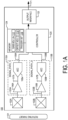
- FIG. 1A is a diagram of an example of a sensor 100, in accordance with one implementation.
- the sensor 100 adjusts the gain and offset of signals that are generated by sensing modules 102A and 102B in the digital domain.
- the sensor 100 may include an angle sensor, and it may be configured to detect a magnetic field that is associated with a rotating target 101.
- the sensor 100 may be configured to generate an output signal 171 that is at least in part indicative of the angular position of the target 101.
- the output signal 171 may indicate one or more of a current angular position of the rotating target 101, speed of rotation of the rotating target 101, direction of rotation of the rotating target 101, acceleration of the rotating target 101, and/or any other characteristic of the movements of the rotating target 101.
- the rotating target 101 may include one more of a permanent magnet (e.g., a 2-pole magnet or a multi-pole magnet), a gear, a transmitting coil, a metal object, the rotor of an electric motor, and/or any other suitable type of target.
- the magnetic field that is associated with the rotating target 101 may include a magnetic field that is generated by the rotating target 101, a magnetic field that is generated by a back bias magnet and modulated by the rotating target 101, a magnetic field that is induced in the rotating target 101 by another magnetic field source, and/or any other suitable type of magnetic field.
- the sensor 100 may include a first sensing module 102A, a first signal path 110A, a second sensing module a 102B, a second signal path 110B, a controller 120, a memory 124, and an output interface 126.
- the sensing module 102A may include one or more magnetic field sensing elements.
- Each of the magnetic field sensing elements may include one or more of a giant magnetoresistor (GMR), a tunnel magnetoresistor (TMR), a Hall effect element, a receiving coil, and/or any other suitable type of magnetic field sensing element.
- GMR giant magnetoresistor
- TMR tunnel magnetoresistor
- Hall effect element a Hall effect element
- receiving coil a receiving coil
- any other suitable type of magnetic field sensing element may have a first axis of maximum sensitivity.
- the sensing module 102B may include one or more magnetic field sensing elements.
- Each of the magnetic field sensing elements may include one or more of a giant magnetoresistor (GMR), a tunnel magnetoresistor (TMR), a Hall effect element, and/or any other suitable type of magnetic field sensing element.
- Each of the magnetic field sensing elements may have a second axis of maximum sensitivity that is perpendicular to the first axis of maximum sensitivity.
- the signal path 110A may include an amplifier 106A and an analog-to-digital converter (ADC) 108A.
- the signal path 110B may include an amplifier 106B and an ADC 108B.
- the controller 120 may include any suitable type of processing circuitry, such as an application-specific integrated circuit (ASIC), a CORDIC processor, a special-purpose processor, synchronous digital logic, asynchronous digital logic, a general-purpose processor (e.g., a MIPS processor, an x86 processor), etc.
- the memory 124 may include any suitable type of volatile and/or non-volatile memory.
- the memory 124 may include a random-access memory (RAM), a dynamic random-access memory (DRAM), an electrically-erasable programmable read-only memory (EEPROM), and/or any other suitable type of memory.
- the output interface 126 may include any suitable type of interface for outputting the output signal 171.
- the output interface 126 may include one or more of a current generator, an Inter-Integrated Circuit (I 2 C) interface, a Controller Area Network (CAN bus) interface, WiFi interface, a local-area network interface, a 5G wireless interface, and/or any other suitable type of interface.
- the sensing module 102A may generate a signal 103A in response to a magnetic field associated with the rotating target 101.
- the amplifier 106A may amplify the signal 103A to produce a signal 107A.
- the ADC 108A may digitize the signal 107A to produce a signal 109A, which is subsequently provided to the controller 120.
- the sensing module 102B may generate a signal 103B in response to a magnetic field associated with the rotating target 101.
- the amplifier 106B may amplify the signal 103B to produce a signal 107B.
- the ADC 108B may digitize the signal 107B to produce a signal 109B, which is subsequently provided to the controller 120.
- the memory 124 may store a gain adjustment coefficient 112, an offset adjustment coefficient 114, and a trigger set 116.
- the gain adjustment coefficient 112 may be used by the controller 120 to adjust the gain of the signal 109A (and/or signal 109B).
- the offset adjustment coefficient may be used by the controller 120 to offset the signal 109A (and/or signal 109B). According to the example of FIG. 1A , the gain and offset of the signal 109A (and/or signal 109B) are adjusted in the digital domain. Adjusting the gain of the signal 109A may include multiplying the signal 109A by the gain adjustment coefficient 112. Offsetting the signal 109A may including adding the offset adjustment coefficient 114 to the signal 109A. It will be understood that the present disclosure is not limited to any specific method for adjusting a signal (generated by a magnetic field sensing element) based on an offset adjustment coefficient and/or a gain adjustment coefficient.
- the controller 120 may execute a process for updating the gain adjustment coefficient 112 and an offset adjustment coefficient 114.
- the process relies on gradient descent to identify optimal (or improved) values for the gain adjustment coefficient 112 and the offset adjustment coefficient.
- the process is discussed further below with respect to FIGS. 2A-4 . Although the process is discussed in the context of a gain adjustment coefficient and an offset adjustment coefficient, it will be understood that the process can be used to update any suitable type of signal adjustment coefficient.
- FIG. 1B is a diagram of an example of a sensor 100, in accordance with another implementation.
- the signal path 110A includes an addition unit 128A for adjusting the offset of the signal 107A, and the amplifier 106A has a variable gain. Furthermore, in the example of FIG. 1B , the signal path 110B includes an addition unit 128B for adjusting the offset of the signal 107B, and the amplifier 106B has a variable gain..
- the controller 120 may generate a signal 112' and provide the signal 112' to each of a digital-to-analog converter (DAC) 130A and a DAC 130B.
- the signal 112' may be equal to (or otherwise based on) the value of the gain adjustment coefficient 112.
- the DAC 130A may convert the signal 112' to analog form to produce a signal 135A, which is subsequently applied at a gain control terminal of the amplifier 106A.
- the DAC 130B may convert the signal 112' to analog form to produce a signal 135B, which is subsequently applied at a gain control terminal of the amplifier 106B.
- the controller 120 may generate a signal 114' and provide the signal 114' to each of a digital-to-analog converter (DAC) 132A and a DAC 132B.
- the signal 114' may be equal to (or otherwise based on) the value of the offset adjustment coefficient 114.
- the DAC 132A may convert the signal 114' to analog form to produce a signal 137A, which is subsequently applied to addition unit 128A.
- the addition unit 128A may add the signal 137A to the signal 107A to produce a signal 129A, which is subsequently provided to the ADC 108A.
- the DAC 132B may convert the signal 114' to analog form to produce a signal 137B, which is subsequently applied to addition unit 128B.
- the addition unit 128B may add the signal 137B to the signal 107B to produce a signal 129B, which is subsequently provided to the ADC 108B.
- FIG. 1B differs from the implementation of FIG. 1A in that the sensor 100 adjusts the gain and offset of signals that are generated by sensing modules 102A and 102B in the analog domain.
- FIG. 1B is provided to illustrate that the controller 120 is not limited to using the gain adjustment coefficients 112 and 114 to adjusting the gain and offset of a signal (generated by a magnetic field sensing element) in the digital domain.
- FIG. 1B illustrates that the gain adjustment coefficient 112 and the offset adjustment coefficient 114 may be used to adjust the gain and/or offset of a signal (generated by a magnetic field sensing element) in the analog domain.
- FIG. 1C is a diagram of an example of a sensor 100, in accordance with yet another implementation.
- FIG. 1C is provided to illustrate that the techniques for updating the values of the gain adjustment coefficient 112 and 114 (which is discussed with respect to FIGS.
- the sensor 100 is an angle sensor, it will be understood that the techniques for updating the values of the gain adjustment coefficient 112 and 114 can be used on any type of magnetic field sensor, such as a current sensor, a position sensor, a proximity sensor, etc.
- each of signals 107A, 129A, and 109A is generated based on a signal 103A, which is generated by the sensing module 102A.
- each of signals 103A, 107A, 129A, and 109A may be referred to as a "signal that is generated at least in part by a magnetic field sensing element" and/or "a signal that is at least in part indicative of the angular position of a target”.
- each of signals 107B, 129B, and 109B is generated based on a signal 103B, which is generated by the sensing module 102B.
- each of signals 103B, 107B, 129B, and 109B may be referred to as a "signal that is generated at least in part by a magnetic field sensing element" and/or "a signal that is at least in part indicative of the angular position of a target".
- signals generated, at least in part, by the sensing modules 102A-B are adjusted based on the same adjustment coefficients.
- the signal generated, at least in part, by the sensing module 102A may be adjusted based on one or more first adjustment coefficients, and the signal generated, at least in part, by the sensing module 102B may be updated based on one or more second adjustment coefficients that are different from the first adjustment coefficients. Any of the first and/or second adjustment coefficients may be updated in accordance with the techniques that are discussed further below.
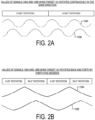
- FIG. 2A is a plot of waveforms of signals 109A and 109B, which result when the rotating target 101 is rotating continuously in the same direction.
- FIG. 2A illustrates that when the target 101 rotates in the same direction, well-defined peaks will be present in the signals 109A and 109B.
- FIG. 2B is a plot of waveforms of signals 109A and 109B, which result when the rotating target 101 rotates back and forth by 35 degrees.
- An example of a target that would exhibit this pattern of rotation is a magnet attached to the rotor of a motor that actuates the windshield wipers of an automobile.
- FIG. 2B illustrates that some patterns of movement of the target 101 may result in the signals 109A and 109B lacking well-defined peaks.
- one advantage of the techniques for adjusting the gain adjustment coefficient 112 and the offset adjustment coefficient 114 is that it works with both signals that have well-defined peaks, as well as with signals that lack well-defined peaks. This is in contrast to some existing techniques for the adjustment of gain and offset adjustment coefficients, which require the presence of well-defined peaks.
- FIG. 2C is a diagram of an example of a model for adjusting the gain adjustment coefficient 112 and/or the offset adjustment coefficient 114.
- the technique is based on minimizing the value of a cost function 210.
- the current value of the gain adjustment coefficient 112 may be the value for the gain adjustment coefficient that is currently stored in the memory 124 (shown in FIGS. 1A-C ).
- the current value of the offset adjustment coefficient 114 is the value for the offset adjustment coefficient that is currently stored in the memory 124 (shown in FIGS. 1A-C ).
- the cost function 210 is based on the error that is present in a single sample of the signal 109A.
- the cost function 210 may be based on the error that is present in more than one sample of the signal 109A.
- the cost function 210 is based on both the gain adjustment coefficient and the offset adjustment coefficient, alternative implementations are possible in which the cost function is based on only one of the gain adjustment coefficient and the offset adjustment coefficient.
- alternative implementations are possible in which the cost function is based on any suitable type of adjustment coefficient.
- function 220 is the partial derivative of the cost function 210 with respect to the gain adjustment coefficient 112.
- function 230 is the partial derivative of the cost function 210 with respect to the offset adjustment coefficient 114.
- Function 240 is based on function 220, and it may be used to update the value of the gain adjustment coefficient 112.
- Function 250 is based on function 230, and it may be used to update the value of the offset adjustment coefficient 112.
- functions 240 and 250 are defined by Equations 6 and 7, respectively:
- a N A c ⁇ ⁇ sin ⁇ A c sin ⁇ + C c ⁇ x
- C N C c ⁇ ⁇ A c sin ⁇ + C c ⁇ x
- a N is a new value of the gain adjustment coefficient 112
- C N is a new value of the offset adjustment coefficient 114
- ⁇ is a learning rate coefficient.
- the learning rate coefficient is a parameter that scales the updates to the gain adjustment coefficient 112 and the offset adjustment coefficient.
- a too-small learning rate can make convergence slow, while a too-high one can create oscillations or even yield divergence.
- the model depicted in FIG. 2C uses gradient descent to find optimal (or improved) values of the gain adjustment coefficient 112 and the offset adjustment coefficient 114 by minimizing the cost function 210.
- the phrase "minimizing a cost function" shall refer to one or both of: (i) finding (or attempting to find) new values for parameters of the cost function (e.g., a new value of a gain adjustment coefficient and/or a new value of an offset adjustment coefficient) that yield a global (or local) minimum of the cost function or (ii) finding (or attempting to find) new values for parameters of the cost function (e.g., a new value of a gain adjustment coefficient and/or a new value of an offset adjustment coefficient) that yield a value of the cost function that is closer to the global (or local) minimum of the cost function than a value yielded by old values of the parameters of the cost function ( e.g., an old value of a gain adjustment coefficient and/or an old value of an offset adjustment coefficient).
- FIG. 2D shows a plot that illustrates how gradient descent can be used to arrive at the value for the gain adjustment coefficient 112, which yields the minimum value of the cost function 210.
- the plot illustrates that the gain adjustment coefficient 112 and/or the offset adjustment coefficient 114 may be updated in incremental steps, which leads to the value of the cost function 210 being minimized.
- the updating of the gain adjustment coefficient 112 and/or the offset adjustment coefficient 114 with new values may be triggered by the rotating target 101 reaching a predetermined angular position. Whether the rotating target 101 has reached the predetermined angular position may be determined based on the current values of - a signal that is generated at least in part by the sensing module 102A, a signal that is generated at least in part by the sensing module 102B, the output signal 171, and or any other suitable signal that is generated within the sensor 100.
- using the angular position of the rotating target 101 as a trigger for updating the values of the gain adjustment coefficient 112 and/or the offset adjustment coefficient 114 allows the updates to be sufficiently spaced across the characteristic of the signals indicative of an angular position. Spacing the updates ensures the angle error minimization is performed over the full operating range of the sensor. The angles at which the update is more often triggered will inherently receive more adjustment.
- FIG. 2E shows an example of the trigger set 116.
- the trigger set 116 provides that the gain adjustment coefficient 112 and/or the offset adjustment coefficient 114 may be updated only when the rotating target 101 is positioned at 30 degrees, 90, degrees, and 120 degrees.
- each element in the trigger set 116 is an angle value
- any of the elements in the trigger set 116 is another quantity that is at least in part indicative of the angular position of the rotating target 101.
- any of the elements in the trigger set 116 may be the value of the signal 109A, which corresponds to a predetermined angular position.
- the controller 120 may implement a state machine to determine whether the current value of the signal 109A should trigger an update of the gain adjustment coefficient 112 and/or offset adjustment coefficient 114.
- FIG. 2F is a plot illustrating values of the signal 109A that would trigger the updating of the gain adjustment coefficient 112 and/or the offset adjustment coefficient 114. Shown in FIG. 2F is a plot 262 of the angular position of the target 101 with respect to time. Further shown in FIG. 2F is a plot of the signal 109A. The plot 262 of the angular position of the target 101 is marked with markers 232, which correspond to different ones of the angular positions in the trigger set 116.
- the plot of the signal 109A is marked with markers 234.
- Each of the markers 234 corresponds to a sample of the signal 109A, which corresponds to one of the angular positions in the trigger set 116, and which could be used to update the coefficients 112 and/or 114. Due to the periodic nature of the waveform of the signal 109A, the values of the signal 109A at each of the points denoted by markers 234 may map to more than one angular position, which necessitates the use of a state machine to determine whether the current value of the signal 109A should trigger an update of the gain adjustment coefficient 112 or the offset adjustment coefficient 114.
- 2E and 2F illustrate that the updating of the gain adjustment coefficient 112 and/or offset adjustment coefficient 114 may be triggered by one or more of: (i) the current angular position of the rotating target 101 matching any of the members of a set of one or more predetermined angular positions, or (ii) the current value of the signal 109A matching any of the members of a set of one or more signal values that correspond to specific angular positions of the rotating target 101.
- the signal 109B or another signal that is generated at least in part by one of sensing elements 102A-B may be used to determine if an update of the coefficients 112 and 114 should be performed.
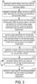
- FIG. 3 is a flowchart of an example of a process 300 that is performed by the sensor 100, according to aspects of the disclosure.
- a first signal is generated that is at least in part indicative of the angular position of the rotating target 101.
- the first signal may be the same or similar to signal 103A or signal 109A.
- a second signal is generated that is at least in part indicative of the angular position of the rotating target 101.
- the second signal may be the same or similar to signal 103B or signal 109B.
- the controller 120 adjusts the gain and offset of the first signal to produce a first adjusted signal.
- the gain and offset of the first signal may be adjusted based on the gain adjustment coefficient 112 and the offset adjustment coefficient 114. As noted above, the gain of the first signal may be adjusted in the digital domain or in the analog domain.
- the controller 120 adjusts the gain and offset of the second signal to produce a second adjusted signal.
- the gain and offset of the second signal may be adjusted based on the gain adjustment coefficient 112 and the offset adjustment coefficient 114.
- the gain of the second signal may be adjusted in the digital domain or in the analog domain.
- both the second signal is adjusted based on the same gain and offset adjustment coefficients as the first signal, it will be understood that in many practical applications the second signal may be adjusted based on different gain and offset adjustment coefficients.
- the controller 120 At step 310, the controller 120 generates an output signal that is at least in part indicative of the angular position of the rotating target 101.
- the output signal may be the same or similar to the output signal 171, which is shown in FIGS. 1A-C .
- the controller 120 detects if the current angular position of the rotating target 101 matches any angular position in a set of one or more angular positions.
- the controller 120 may detect if the current angular position matches any member of the trigger set 116.
- the controller 120 may perform a search of the memory 124 to determine whether the trigger set 116 includes an element that matches the current angular position of the rotating target 101.
- the controller 120 may use a state machine to determine whether the current value of the first signal (and/or the current value of the second signal) corresponds to any angular positions in a set of one or more angular positions (such as the trigger set 116).
- the current angular position of the rotating target matches any angular position of the set of one or more angular position if the angular position from the set is the same as (or within a predetermined distance from) the current angular position.
- the current angular position of the rotating target 101 may match any of the angular positions in the set if the rotating target 101 has crossed ( i.e., rotated past) the position. If the current angular position of the rotating target 101 is determined to match any angular position in a set of one or more angular positions, the process 300 proceeds to step 314. Otherwise, step 314 is repeated.
- at least one of the gain adjustment coefficient and the offset adjustment coefficient may be updated in accordance with the model that is discussed with respect to FIG. 2C .
- at least one of the gain adjustment coefficient 112 and the offset adjustment coefficient 114 may be updated by executing a process 400, which is discussed further below with respect to FIG. 4 .
- the second signal is adjusted based on the gain adjustment coefficient 112 and the offset adjustment coefficient 114
- the offset and gain adjustment coefficients may also be updated by using the model of FIG. 2C and/or executing the process 400.
- both a first signal and a second signal are used to determine the angular position of the rotating target 101, it will be understood that alternative implementations are possible in which only the first signal is used ( e.g., see FIG. 1C ) or in which more than two signals are used.
- steps 312 and 314 are executed in each iteration of the process 300, it will be understood that steps 312 may and 314 may be executed only until a predetermined convergence criterion is satisfied.
- the convergence criterion may be satisfied when: (i) the difference between a new value of the gain adjustment coefficient 112 and a current value of the gain adjustment coefficient 112 is less than a first threshold, and/or (ii) when the difference between a new value of the offset adjustment coefficient and a current value of the offset adjustment coefficient is less than a second threshold.
- the present disclosure is not limited to any specific convergence criterion.
- step 314 is performed only when the triggering condition of step 312 is satisfied, it will be understood that alternative implementations are possible in which the execution of step 314 is not subject to any triggering condition being satisfied.
- the triggering condition of step 312 is based on the current angular position of the rotating target 101, it will be understood that the present disclosure is not limited to any specific type of triggering condition.
- the triggering condition of step 312 may be based on time. In such implementations, step 314 may be executed only if a sufficient amount of time has passed since the most recent execution of step 314.
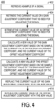
- FIG. 4 is a flowchart of an example of a process 400 for updating the values of a gain adjustment coefficient and/or an offset adjustment coefficient, according to aspects of the disclosure.
- the controller 120 retrieves a sample of a signal. According to the present example, the controller 120 retrieves a sample of the signal 109A.
- the controller 120 retrieves the current value of a gain adjustment coefficient that is being used to adjust the signal. According to one example, the controller 120 retrieves the current value of the gain adjustment coefficient 112 from the memory 124.
- the controller 120 retrieves the current value of an offset adjustment coefficient that is being used to adjust the signal. According to the present example, the controller 120 retrieves the current value of the offset adjustment coefficient 114 from the memory 124.
- the controller 120 calculates a new value for the gain adjustment coefficient that is being used to adjust the signal.
- the new value is calculated based on the sample (retrieved at step 402), the current value of the gain adjustment coefficient (retrieved at step 404), and the current value of the offset adjustment coefficient (retrieved at step 406).
- the new value of the gain adjustment coefficient may be calculated using the approach that is discussed above with respect to FIG. 2C . Additionally or alternatively, in some implementations, the new value of the gain adjustment coefficient may be calculated by minimizing a cost function that approximates (or is otherwise based on) the error that is present in the sample (retrieved at step 402). Additionally or alternatively, in some implementations, the new value of the gain adjustment coefficient may be calculated in accordance with function 240, which is discussed above with respect to FIG. 2C .
- the controller 120 calculates a new value for the offset adjustment coefficient that is being used to adjust the signal.
- the new value is calculated based on the sample (retrieved at step 402), the current value of the gain adjustment coefficient (retrieved at step 404), and the current value of the offset adjustment coefficient (retrieved at step 406).
- the new value of the offset adjustment coefficient may be calculated using the approach that is discussed above with respect to FIG. 2C . Additionally or alternatively, in some implementations, the new value of the offset adjustment coefficient may be calculated by minimizing a cost function that approximates (or is otherwise based on) the error that is present in the sample (retrieved at step 402). Additionally or alternatively, in some implementations, the new value of the offset adjustment coefficient may be calculated in accordance with function 240, which is discussed above with respect to FIG. 2 .
- the controller replaces the current value of the gain adjustment coefficient (retrieved at step 404) with the new value of the gain adjustment coefficient (calculated at step 408).
- replacing the current value of the gain adjustment coefficient with the new value of the gain adjustment coefficient includes overwriting the value of the gain adjustment coefficient 112, which is stored in the memory 124 with the value that is calculated at step 408.
- the new value of the gain adjustment coefficient is written to the memory 124, it becomes the "current" value of the gain adjustment coefficient, and begins to be used by the controller 120 to adjust the gain of the signal 109A.
- the controller replaces the current value of the offset adjustment coefficient (retrieved at step 404) with the new value of the offset adjustment coefficient (calculated at step 408).
- replacing the current value of the offset adjustment coefficient with the new value of the offset adjustment coefficient includes overwriting the value of the offset adjustment coefficient 114, which is stored in the memory 124 with the value that is calculated at step 410.
- the new value of the offset adjustment coefficient is written to the memory 124, it becomes the "current" value of the offset adjustment coefficient, and begins to be used by the controller 120 to adjust the offset of the signal 109A.
- FIGS. 2A-4 uses gradient descent to repeatedly update the values of the gain adjustment coefficient 112 and the offset adjustment coefficient 114. As the values are updated, the amount of error that is present in the signal 109A is decreased.
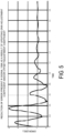
- FIG. 5 shows a plot of the error that is present in signal 109A as the values of the gain adjustment coefficient 112 and the offset adjustment coefficient 114 are sequentially updated. The plot shows that as the updating of coefficients 112 and 114 progresses, the error in the signal 109A decreases.
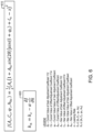
- FIG. 6 shows another model for updating different types of adjustment coefficients.
- FIG. 6 is provided to illustrate that the concepts and ideas discussed above are not limited to the updating of a gain adjustment coefficient or an offset adjust coefficient only, and can be extended to updating any type of adjustment coefficient.
- the model of FIG. 6 is based on minimizing the value of cost function 610 with respect to adjustment coefficients A c , C c , ⁇ c , A hc , where A c is the current value of a gain adjustment coefficient, C c is the current value of an offset adjustment coefficient, ⁇ c is the current value of a phase adjustment coefficient, and A hc is the current value of a first-order harmonic adjustment coefficient.
- Equation 9 provides that a new value for any of the adjustment coefficients A c , C c , ⁇ c , A hc may be calculated by subtracting, from the current value of the same adjustment coefficient, a scaled (by a learning rate coefficient) or non-scaled value of the partial derivative of cost function 610 with respect to that coefficient.
- Cost function 610 may be used to determine the value of fewer than all of the offset adjustment coefficient, the gain adjustment coefficient, the first-order harmonic adjustment coefficient, and the phase adjustment coefficient. Equation 10 can be derived from cost function 610, and can be used to update the values of a gain adjustment coefficient, an offset adjustment coefficient, and a phase adjustment coefficient. Similarly, Equation 11 can be derived from cost function 610, and can be used to update a first-order harmonic adjustment coefficient only.
- J A c C c ⁇ c 1 2 A c sin ⁇ + ⁇ c + C c ⁇ x 2
- J A hc 1 2 A c 1 + A hc sin 2 ⁇ sin ⁇ + C c ⁇ x 2
- a signal generated, at least in part, by a magnetic field sensing element in response to a magnetic field associated with a rotating target may be adjusted in accordance with any of Equations 12-14 below.
- the signal of interest is the same or similar to signal 109A.
- a c is the current value of a gain adjustment coefficient
- C c is the current value of an offset adjustment coefficient
- ⁇ is the current value of a phase adjustment coefficient
- a hc is the current value of a first-order harmonic adjustment coefficient
- x a is an adjusted sample of the signal of interest ( e.g ., the signal 109A)
- x s is a raw sample of the signal of interest (e.g., the signal 109A)
- y s is a raw (or adjusted) sample of another signal (e.g., the signal 109B).
- FIG. 6 is provided as an example only, and the present disclosure is not limited to using any specific cost function for updating the values of one or more adjustment coefficients, for as long as the cost function is at least partially indicative of the error that is present in a signal generated by a magnetic field sensing element in response to a magnetic field associated with a rotating target.
- FIG. 7 is a flowchart of an example of a process 700 that is performed by the sensor 100, according to aspects of the disclosure.
- the process 700 may be performed by a controller of a magnetic field sensor, such as the sensor 100.
- a signal is generated that is at least in part indicative of the angular position of a rotating target.
- the signal may be the same or similar to the signal 109A and the rotating target may be the same or similar to the rotating target 101, both of which are discussed above with respect to FIGS. 1A-C .
- the signal is adjusted to produce an adjusted signal.
- the signal may be adjusted based on an adjustment coefficient.
- the adjustment coefficient may include any suitable type of adjustment coefficient.
- the adjustment coefficient may include a gain adjustment coefficient, an offset adjustment coefficient, a phase adjustment coefficient, a first-order harmonic adjustment coefficient, a second-order harmonic adjustment coefficient, a third-order harmonic adjustment coefficient, a fourth-order harmonic adjustment coefficient, and other features describing error patterns.
- an output signal is generated that is at least in part indicative of the angular position of the rotating target.
- the output signal may be the same or similar to the output signal 171, which is discussed above with respect to FIGS. 1A-C .
- a determination is made if the current angular position of the rotating target matches any angular position in the set of one or more angular positions. Step 708 may be performed in the manner discussed with respect to step 312 of the process 300 (shown in FIG. 3 ).
- the adjustment coefficient is updated. In some implementations, the adjustment coefficient may be updated by executing a process 800, which is discussed further below with respect to FIG. 8 .
- FIG. 8 is a flowchart of an example of a process 800 for updating an adjustment coefficient, according to aspects of the disclosure.
- the process 800 may be performed by a controller of a magnetic field sensor, such as the sensor 100.
- a sample of a signal is retrieved.
- the signal may be the same or similar to the signal 109A, which is discussed with respect to FIGS. 1A-C .
- the controller 120 retrieves the current of an adjustment coefficient that is used to adjust the signal (either before or after the signal is sampled).
- the adjustment coefficient may include any suitable type of adjustment coefficient.
- the adjustment coefficient may include a gain adjustment coefficient, an offset adjustment coefficient, a phase adjustment coefficient, a first-order harmonic adjustment coefficient, a second-order harmonic adjustment coefficient, a third-order harmonic adjustment coefficient, a fourth-order harmonic adjustment coefficient, etc.
- the controller 120 calculates a new value for the adjustment coefficient.
- the new value may be calculated by minimizing a cost function, such as the cost function 610 (which is shown in FIG. 6 ). However, it will be understood that the present disclosure is not limited to using any specific type of cost function.
- the current value of the adjustment coefficient is replaced with the new value of the adjustment coefficient. Replacing the current value of the adjustment coefficient may include overwriting (in memory) the current value of the adjustment coefficient with the new value of the adjustment coefficient.
- unit shall refer to an electronic component and/or an electronic circuit that include one or more electronic components.
- the electronic components may include analog components (e.g ., electronic components that operate in the analog domain). Additionally or alternatively, in some implementations, the electronic components may include digital logic and/or electronic components that operate in the digital domain. Additionally or alternatively, in some implementations, the electronic components may include digital logic that is configured to execute a sensor firmware. It will be understood that the meaning of the term “compensation unit” includes, but not limited to the examples provided throughout the disclosure. It will be understood that the meaning of the term “conditioning unit” includes, but not limited to the examples provided throughout the disclosure.
- offsetting unit includes, but not limited to the examples provided throughout the disclosure. It will be further understood that the meaning of the term “de-offsetting unit” includes, but not limited to the examples provided throughout the disclosure. Stated succinctly, the term "unit,” as used throughout the disclosure is not intended to be construed as means-plus-function language.
- the system may be implemented, at least in part, via a computer program product, (e.g . , in a non-transitory machine-readable storage medium such as, for example, a non-transitory computer-readable medium), for execution by, or to control the operation of, data processing apparatus (e.g., a programmable processor, a computer, or multiple computers).
- a computer program product e.g . , in a non-transitory machine-readable storage medium such as, for example, a non-transitory computer-readable medium
- data processing apparatus e.g., a programmable processor, a computer, or multiple computers.
- Each such program may be implemented in a high-level procedural or object-oriented programming language to work with the rest of the computer-based system. However, the programs may be implemented in assembly, machine language, or Hardware Description Language.
- the language may be a compiled or an interpreted language, and it may be deployed in any form, including as a stand-alone program or as a module, component, subroutine, or another unit suitable for use in a computing environment.
- a computer program may be deployed to be executed on one computer or multiple computers at one site or distributed across multiple sites and interconnected by a communication network.
- a computer program may be stored on a non-transitory machine-readable medium that is readable by a general or special purpose programmable computer for configuring and operating the computer when the non-transitory machine-readable medium is read by the computer to perform the processes described herein.
- processes described herein may also be implemented as a non-transitory machine-readable storage medium, configured with a computer program, where upon execution, instructions in the computer program cause the computer to operate in accordance with the processes.
- a non-transitory machine-readable medium may include but is not limited to a hard drive, compact disc, flash memory, non-volatile memory, volatile
- a magnetic field sensing element can include one or more magnetic field sensing elements, such as Hall effect elements, magnetoresistance elements, or magnetoresistors, and can include one or more such elements of the same or different types.
- Hall effect elements for example, a planar Hall element, a vertical Hall element, and a Circular Vertical Hall (CVH) element.
- magnetoresistance elements for example, a semiconductor magnetoresistance element such as Indium Antimonide (InSb), a giant magnetoresistance (GMR) element, for example, a spin valve, an anisotropic magnetoresistance element (AMR), a tunneling magnetoresistance (TMR) element, and a magnetic tunnel junction (MTJ).
- the magnetic field sensing element may be a single element or, alternatively, may include two or more magnetic field sensing elements arranged in various configurations, e.g., a half bridge or full (Wheatstone) bridge.
- the magnetic field sensing element may be a device made of a type IV semiconductor material such as Silicon (Si) or Germanium (Ge), or a type III-V semiconductor material like Gallium-Arsenide (GaAs) or an Indium compound, e.g., Indium-Antimonide (In.Sb).
- a type IV semiconductor material such as Silicon (Si) or Germanium (Ge)
- a type III-V semiconductor material like Gallium-Arsenide (GaAs) or an Indium compound, e.g., Indium-Antimonide (In.Sb).
Landscapes
- Physics & Mathematics (AREA)
- General Physics & Mathematics (AREA)
- Condensed Matter Physics & Semiconductors (AREA)
- Engineering & Computer Science (AREA)
- Technology Law (AREA)
- Transmission And Conversion Of Sensor Element Output (AREA)
Abstract
Description
- As is known, sensors are used to perform various functions in a variety of applications. Some sensors include one or magnetic field sensing elements, such as a Hall effect element or a magnetoresistive element, to sense a magnetic field associated with proximity or motion of a target object, such as a ferromagnetic object in the form of a gear or ring magnet, or to sense a current, as examples. Sensor integrated circuits are widely used in automobile control systems and other safety-critical applications. There are a variety of specifications that set forth requirements related to permissible sensor quality levels, failure rates, and overall functional safety.
- According to aspects of the disclosure, a method is provided for use in a sensor, comprising: generating a signal that is indicative of an angular position of a rotating target, the signal being generated by at least one magnetic field sensing element; adjusting the signal to produce an adjusted signal, the signal being adjusted based on a current value of a first adjustment coefficient; generating an output signal based on the adjusted signal; and updating the first adjustment coefficient, the updating including replacing the current value of the first adjustment coefficient with a new value of the first adjustment coefficient, the updating being performed by minimizing a function that is based on the current value of the first adjustment coefficient.
- In an embodiment, the signal is adjusted further based on a current value of a second adjustment coefficient and the function is further based on the current value of the second adjustment coefficient, and the second adjustment coefficient is also updated by minimizing the function.
- In an embodiment, the method further comprises: detecting a current angular position of the rotating target by using the adjusted signal; and detecting whether the current angular position of the rotating target matches any angular position in a set of one or more angular positions, wherein the updating of the first adjustment coefficient is triggered by the current angular position of the rotating target matching any of the angular positions in the set of one or more angular positions.
- In an embodiment, the function is based on an error that is present in an arbitrary sample of the signal or in multiple samples of the signal.
- In an embodiment, the first adjustment coefficient includes at least one of a gain adjustment coefficient, an offset adjustment coefficient, a phase adjustment coefficient, and a harmonic adjustment coefficient.
- In an embodiment, the first adjustment coefficient is updated based on a derivative of the function with respect to the first adjustment coefficient.
- In an embodiment, the first adjustment coefficient includes a gain adjustment coefficient, and the function has the form of:

- In an embodiment, the updating of the first adjustment coefficient is triggered by the signal having a value that is associated with a predetermined angular position.
- In an embodiment, the signal is adjusted further based on a current value of a second adjustment coefficient and the function is further based on the current value of the second adjustment coefficient, the second adjustment coefficient is also updated by minimizing the function, the first adjustment coefficient includes a gain adjustment coefficient, and the second adjustment coefficient includes an offset adjustment coefficient.
- In an embodiment, the rotating target includes at least one of a magnet, a gear, a ring-magnet, and a rotor of an electric motor; and the magnetic field sensing element includes at least one of a Hall effect element, a giant magnetoresistor (GMR), or a tunnel magnetoresistor (TMR).
- According to aspects of the disclosure, a sensor is provided, comprising: at least one magnetic field sensing element that is arranged to generate a signal that is indicative of an angular position of a rotating target; and a processing circuitry configured to: adjust the signal to produce an adjusted signal, the signal being adjusted based on a current value of a first adjustment coefficient; generate an output signal based on the adjusted signal; and update the first adjustment coefficient, the updating including replacing the current value of the first adjustment coefficient with a new value of the first adjustment coefficient, the updating being performed by minimizing a function that is based on the current value of the first adjustment coefficient.
- In an embodiment, the signal is adjusted further based on a current value of a second adjustment coefficient and the function is further based on the current value of the second adjustment coefficient, and the second adjustment coefficient is also updated by minimizing the function.
- In an embodiment, wherein: the processing circuitry is configured to detect a current angular position of the rotating target by using the adjusted signal, and detect whether the current angular position of the rotating target matches any angular position in a set of one or more angular positions, and the updating of the first adjustment coefficient is triggered by the current angular position of the rotating target matching any of the angular positions in the set of one or more angular positions.
- In an embodiment, the function is based on an error that is present in an arbitrary sample of the signal or in multiple samples of the signal.
- In an embodiment, the first adjustment coefficient includes at least one of a gain adjustment coefficient, an offset adjustment coefficient, a phase adjustment coefficient, and a harmonic adjustment coefficient.
- In an embodiment, the first adjustment coefficient is updated based on a derivative of the function with respect to the first adjustment coefficient.
- In an embodiment, the first adjustment coefficient includes a gain adjustment coefficient, and the function has the form of:

- In an embodiment, the updating of the first adjustment coefficient is triggered by the signal having a value that is associated with a predetermined angular position.
- In an embodiment, the signal is adjusted further based on a current value of a second adjustment coefficient and the function is further based on the current value of the second adjustment coefficient, the second adjustment coefficient is also updated by minimizing the function, the first adjustment coefficient includes a gain adjustment coefficient, and the second adjustment coefficient includes an offset adjustment coefficient.
- In an embodiment, the rotating target includes at least one of a magnet, a gear, a ring-magnet, and a rotor of an electric motor; and the magnetic field sensing element includes at least one of a Hall effect element, a giant magnetoresistor (GMR), or a tunnel magnetoresistor (TMR).
- According to aspects of the disclosure, a non-transitory computer-readable medium storing one or more processor-executable instructions, which, when executed by a processing circuitry of a sensor, cause the processing circuitry to perform the operations of comprising: generating a signal that is indicative of an angular position of a rotating target, the signal being generated by at least one magnetic field sensing element; adjusting the signal to produce an adjusted signal, the signal being adjusted based on a current value of a first adjustment coefficient; generating an output signal based on the adjusted signal; and updating the first adjustment coefficient, the updating including replacing the current value of the first adjustment coefficient with a new value of the first adjustment coefficient, the updating being performed by minimizing a function that is based on the current value of the first adjustment coefficient.
- In an embodiment, the signal is adjusted further based on a current value of a second adjustment coefficient and the function is further based on the current value of the second adjustment coefficient, and the second adjustment coefficient is also updated by minimizing the function.
- In an embodiment, the one or more processor-executable instructions, which when executed by the processing circuitry, further cause the processing circuitry to perform the operations of: detecting a current angular position of the rotating target by using the adjusted signal, and detecting whether the current angular position of the rotating target matches any angular position in a set of one or more angular positions, and the updating of the first adjustment coefficient is triggered by the current angular position of the rotating target matching any of the angular positions in the set of one or more angular positions.
- In an embodiment, the function is based on an error that is present in an arbitrary sample of the signal or in multiple samples of the signal.
- In an embodiment, the first adjustment coefficient includes at least one of a gain adjustment coefficient, an offset adjustment coefficient, a phase adjustment coefficient, and a harmonic adjustment coefficient.
- According to aspects of the disclosure, a system is provided, comprising: means for generating a signal that is indicative of an angular position of a rotating target, the signal being generated by at least one magnetic field sensing element; means for adjusting the signal to produce an adjusted signal, the signal being adjusted based on a current value of a first adjustment coefficient; means for generating an output signal based on the adjusted signal; and means for updating the first adjustment coefficient, the updating including replacing the current value of the first adjustment coefficient with a new value of the first adjustment coefficient, the updating being performed by minimizing a function that is based on the current value of the first adjustment coefficient.
- The foregoing features may be more fully understood from the following description of the drawings in which:
-
FIG. 1A is a diagram of an example of a sensor, according to aspects of the disclosure; -
FIG. 1B is a diagram of an example of a sensor, according to aspects of the disclosure; -
FIG. 1C is a diagram of an example of a sensor, according to aspects of the disclosure; -
FIG. 2A is a plot of signals generated by magnetic field sensing elements, according to aspects of the disclosure; -
FIG. 2B is a plot of signals generated by magnetic field sensing elements, according to aspects of the disclosure; -
FIG. 2C is a diagram of a model for updating adjustment coefficients, according to aspects of the disclosure; -
FIG. 2D is a plot illustrating aspects of the model ofFIG. 2C , according to aspects of the disclosure; -
FIG. 2E is a diagram of an example of a set of angular positions of a rotating target that trigger the updating of a gain adjustment and/or an offset adjustment coefficient, according to aspects of the disclosure; -
FIG. 2F is a plot of an example of a condition that triggers the updating of a gain adjustment and/or an offset adjustment coefficient, according to aspects of the disclosure; -
FIG. 3 is a flowchart of an example of a process, according to aspects of the disclosure; -
FIG. 4 is a flowchart of an example of a process, according to aspects of the disclosure; -
FIG. 5 is a plot illustrating an example of results that can be achieved with the process ofFIG. 4 , according to aspects of the disclosure; -
FIG. 6 is a diagram of a model for updating adjustment coefficients, according to aspects of the disclosure; -
FIG. 7 is a flowchart of an example of a process, according to aspects of the disclosure; -
FIG. 8 is a flowchart of an example of a process, according to aspects of the disclosure. -
FIG. 1A is a diagram of an example of asensor 100, in accordance with one implementation. In this implementation, thesensor 100 adjusts the gain and offset of signals that are generated bysensing modules sensor 100 may include an angle sensor, and it may be configured to detect a magnetic field that is associated with arotating target 101. Thesensor 100 may be configured to generate anoutput signal 171 that is at least in part indicative of the angular position of thetarget 101. By way of example, theoutput signal 171 may indicate one or more of a current angular position of therotating target 101, speed of rotation of therotating target 101, direction of rotation of therotating target 101, acceleration of therotating target 101, and/or any other characteristic of the movements of therotating target 101. - The
rotating target 101 may include one more of a permanent magnet (e.g., a 2-pole magnet or a multi-pole magnet), a gear, a transmitting coil, a metal object, the rotor of an electric motor, and/or any other suitable type of target. The magnetic field that is associated with therotating target 101 may include a magnetic field that is generated by therotating target 101, a magnetic field that is generated by a back bias magnet and modulated by therotating target 101, a magnetic field that is induced in therotating target 101 by another magnetic field source, and/or any other suitable type of magnetic field. - As illustrated, the
sensor 100 may include afirst sensing module 102A, afirst signal path 110A, a second sensing module a 102B, asecond signal path 110B, acontroller 120, amemory 124, and anoutput interface 126. - The
sensing module 102A may include one or more magnetic field sensing elements. Each of the magnetic field sensing elements may include one or more of a giant magnetoresistor (GMR), a tunnel magnetoresistor (TMR), a Hall effect element, a receiving coil, and/or any other suitable type of magnetic field sensing element. Each of the magnetic field sensing elements in thesensing module 102A may have a first axis of maximum sensitivity. - The
sensing module 102B may include one or more magnetic field sensing elements. Each of the magnetic field sensing elements may include one or more of a giant magnetoresistor (GMR), a tunnel magnetoresistor (TMR), a Hall effect element, and/or any other suitable type of magnetic field sensing element. Each of the magnetic field sensing elements may have a second axis of maximum sensitivity that is perpendicular to the first axis of maximum sensitivity. As a result of this arrangement, a signal generated, at least in part, by one ofsensing modules 102A-B may have sinusoidal waveform, and a signal generated, at least in part, by the other one ofsensing modules 102A-B may have a cosine waveform. - The
signal path 110A may include anamplifier 106A and an analog-to-digital converter (ADC) 108A. Thesignal path 110B may include anamplifier 106B and anADC 108B. Thecontroller 120 may include any suitable type of processing circuitry, such as an application-specific integrated circuit (ASIC), a CORDIC processor, a special-purpose processor, synchronous digital logic, asynchronous digital logic, a general-purpose processor (e.g., a MIPS processor, an x86 processor), etc. Thememory 124 may include any suitable type of volatile and/or non-volatile memory. By way of example, thememory 124 may include a random-access memory (RAM), a dynamic random-access memory (DRAM), an electrically-erasable programmable read-only memory (EEPROM), and/or any other suitable type of memory. Theoutput interface 126 may include any suitable type of interface for outputting theoutput signal 171. For example, theoutput interface 126 may include one or more of a current generator, an Inter-Integrated Circuit (I2C) interface, a Controller Area Network (CAN bus) interface, WiFi interface, a local-area network interface, a 5G wireless interface, and/or any other suitable type of interface. - In operation, the
sensing module 102A may generate asignal 103A in response to a magnetic field associated with therotating target 101. Theamplifier 106A may amplify thesignal 103A to produce asignal 107A. TheADC 108A may digitize thesignal 107A to produce asignal 109A, which is subsequently provided to thecontroller 120. - The
sensing module 102B may generate asignal 103B in response to a magnetic field associated with therotating target 101. Theamplifier 106B may amplify thesignal 103B to produce asignal 107B. TheADC 108B may digitize thesignal 107B to produce asignal 109B, which is subsequently provided to thecontroller 120. - The
memory 124 may store again adjustment coefficient 112, an offsetadjustment coefficient 114, and atrigger set 116. Thegain adjustment coefficient 112 may be used by thecontroller 120 to adjust the gain of thesignal 109A (and/or signal 109B). The offset adjustment coefficient may be used by thecontroller 120 to offset thesignal 109A (and/or signal 109B). According to the example ofFIG. 1A , the gain and offset of thesignal 109A (and/or signal 109B) are adjusted in the digital domain. Adjusting the gain of thesignal 109A may include multiplying thesignal 109A by thegain adjustment coefficient 112. Offsetting thesignal 109A may including adding the offsetadjustment coefficient 114 to thesignal 109A. It will be understood that the present disclosure is not limited to any specific method for adjusting a signal (generated by a magnetic field sensing element) based on an offset adjustment coefficient and/or a gain adjustment coefficient. - The
controller 120 may normalizesignals controller 120 may use the normalizedsignals rotating target 101 in accordance withEquation 1 below:
rotating target 101, S109A is the value ofsignal 109A and S109B is the value ofsignal 109B. After the angular position of therotating target 101 is determined, thecontroller 120 may generate theoutput signal 171 based on the determined angular position. - In addition, the
controller 120 may execute a process for updating thegain adjustment coefficient 112 and an offsetadjustment coefficient 114. The process relies on gradient descent to identify optimal (or improved) values for thegain adjustment coefficient 112 and the offset adjustment coefficient. The process is discussed further below with respect toFIGS. 2A-4 . Although the process is discussed in the context of a gain adjustment coefficient and an offset adjustment coefficient, it will be understood that the process can be used to update any suitable type of signal adjustment coefficient. -
FIG. 1B is a diagram of an example of asensor 100, in accordance with another implementation. - According to the example of
FIG. 1B , thesignal path 110A includes anaddition unit 128A for adjusting the offset of thesignal 107A, and theamplifier 106A has a variable gain. Furthermore, in the example ofFIG. 1B , thesignal path 110B includes anaddition unit 128B for adjusting the offset of thesignal 107B, and theamplifier 106B has a variable gain.. - According to the example of
FIG. 1B , thecontroller 120 may generate a signal 112' and provide the signal 112' to each of a digital-to-analog converter (DAC) 130A and aDAC 130B. The signal 112' may be equal to (or otherwise based on) the value of thegain adjustment coefficient 112. TheDAC 130A may convert the signal 112' to analog form to produce asignal 135A, which is subsequently applied at a gain control terminal of theamplifier 106A. TheDAC 130B may convert the signal 112' to analog form to produce asignal 135B, which is subsequently applied at a gain control terminal of theamplifier 106B. - According to the example of
FIG. 1B , thecontroller 120 may generate a signal 114' and provide the signal 114' to each of a digital-to-analog converter (DAC) 132A and aDAC 132B. The signal 114' may be equal to (or otherwise based on) the value of the offsetadjustment coefficient 114. TheDAC 132A may convert the signal 114' to analog form to produce asignal 137A, which is subsequently applied toaddition unit 128A. Theaddition unit 128A may add thesignal 137A to thesignal 107A to produce asignal 129A, which is subsequently provided to theADC 108A. TheDAC 132B may convert the signal 114' to analog form to produce a signal 137B, which is subsequently applied toaddition unit 128B. Theaddition unit 128B may add the signal 137B to thesignal 107B to produce asignal 129B, which is subsequently provided to theADC 108B. - The implementation of
FIG. 1B differs from the implementation ofFIG. 1A in that thesensor 100 adjusts the gain and offset of signals that are generated by sensingmodules FIG. 1B is provided to illustrate that thecontroller 120 is not limited to using thegain adjustment coefficients FIG. 1B , in other words, illustrates that thegain adjustment coefficient 112 and the offsetadjustment coefficient 114 may be used to adjust the gain and/or offset of a signal (generated by a magnetic field sensing element) in the analog domain. -
FIG. 1C is a diagram of an example of asensor 100, in accordance with yet another implementation. In this implementation, thesecond signal path 110B is omitted and thecontroller 120 uses a different method to determine the angular position of the rotating target. More specifically, the controller counts the peaks in thesignal 109A and determines the current angular position of the rotating target in accordance withEquation 2 below:
signal 109A, and P is the number of peaks that occur in thesignal 109A during each full rotation of therotating target 101.FIG. 1C is provided to illustrate that the techniques for updating the values of thegain adjustment coefficient 112 and 114 (which is discussed with respect toFIGS. 2A-4 ) can be used on any type of magnetic field sensor, irrespective of how the magnetic signal sensor processes one or more signals that are generated by magnetic field sensing elements, and irrespective of the number of channels that are available in the sensor. Furthermore, although in the examples ofFIGS. 1A-C thesensor 100 is an angle sensor, it will be understood that the techniques for updating the values of thegain adjustment coefficient - In some respects, each of
signals signal 103A, which is generated by thesensing module 102A. Under the nomenclature of the present disclosure, each ofsignals signals signal 103B, which is generated by thesensing module 102B. Under the nomenclature of the present disclosure, each ofsignals FIGS. 1A-B , signals generated, at least in part, by thesensing modules 102A-B are adjusted based on the same adjustment coefficients. However, it will be understood that in practice, the signal generated, at least in part, by thesensing module 102A may be adjusted based on one or more first adjustment coefficients, and the signal generated, at least in part, by thesensing module 102B may be updated based on one or more second adjustment coefficients that are different from the first adjustment coefficients. Any of the first and/or second adjustment coefficients may be updated in accordance with the techniques that are discussed further below. -
FIG. 2A is a plot of waveforms ofsignals rotating target 101 is rotating continuously in the same direction.FIG. 2A illustrates that when thetarget 101 rotates in the same direction, well-defined peaks will be present in thesignals FIG. 2B is a plot of waveforms ofsignals rotating target 101 rotates back and forth by 35 degrees. An example of a target that would exhibit this pattern of rotation is a magnet attached to the rotor of a motor that actuates the windshield wipers of an automobile.FIG. 2B illustrates that some patterns of movement of thetarget 101 may result in thesignals gain adjustment coefficient 112 and the offsetadjustment coefficient 114 is that it works with both signals that have well-defined peaks, as well as with signals that lack well-defined peaks. This is in contrast to some existing techniques for the adjustment of gain and offset adjustment coefficients, which require the presence of well-defined peaks. -
FIG. 2C is a diagram of an example of a model for adjusting thegain adjustment coefficient 112 and/or the offsetadjustment coefficient 114. The technique is based on minimizing the value of acost function 210. In the present example, thecost function 210 is defined byEquation 3 below:
gain adjustment coefficient 112, Cc is the current value of the offsetadjustment coefficient 114, θ is the current angular position of the rotating target, and x is a sample of the signal. Under the nomenclature of the present disclosure, the current value of thegain adjustment coefficient 112 may be the value for the gain adjustment coefficient that is currently stored in the memory 124 (shown inFIGS. 1A-C ). The current value of the offsetadjustment coefficient 114 is the value for the offset adjustment coefficient that is currently stored in the memory 124 (shown inFIGS. 1A-C ). - In the present example, the
cost function 210 is based on the error that is present in a single sample of thesignal 109A. However, it will be understood that the present disclosure is not limited to any specific type of cost function. For example, in some implementations, thecost function 210 may be based on the error that is present in more than one sample of thesignal 109A. Furthermore, although in the present example, thecost function 210 is based on both the gain adjustment coefficient and the offset adjustment coefficient, alternative implementations are possible in which the cost function is based on only one of the gain adjustment coefficient and the offset adjustment coefficient. Furthermore, alternative implementations are possible in which the cost function is based on any suitable type of adjustment coefficient. - Further shown in
FIG. 2C are the values of the partial derivatives of thecost function 210. Specifically, function 220 is the partial derivative of thecost function 210 with respect to thegain adjustment coefficient 112. And function 230 is the partial derivative of thecost function 210 with respect to the offsetadjustment coefficient 114. In the present examples, functions 220 and 230 are defined byEquations 4 and 5, respectively:

- Further shown in
FIG. 2C arefunctions Function 240 is based onfunction 220, and it may be used to update the value of thegain adjustment coefficient 112.Function 250 is based onfunction 230, and it may be used to update the value of the offsetadjustment coefficient 112. In the present examples, functions 240 and 250 are defined byEquations 6 and 7, respectively:

gain adjustment coefficient 112, CN is a new value of the offsetadjustment coefficient 114, and α is a learning rate coefficient. The learning rate coefficient is a parameter that scales the updates to thegain adjustment coefficient 112 and the offset adjustment coefficient. A too-small learning rate can make convergence slow, while a too-high one can create oscillations or even yield divergence. In the present example, the value of the learning rate sets how aggressively the values of thegain adjustment coefficient 112 and the offsetadjustment coefficient 114 are updated. According to the present example, α = 0.5. However, it will be understood that the present disclosure is not limited to any specific value of the learning rate coefficients. Additionally the learning rate can decay or vary over time. - In some respects, the model depicted in
FIG. 2C uses gradient descent to find optimal (or improved) values of thegain adjustment coefficient 112 and the offsetadjustment coefficient 114 by minimizing thecost function 210. As used throughout the disclosure, the phrase "minimizing a cost function" shall refer to one or both of: (i) finding (or attempting to find) new values for parameters of the cost function (e.g., a new value of a gain adjustment coefficient and/or a new value of an offset adjustment coefficient) that yield a global (or local) minimum of the cost function or (ii) finding (or attempting to find) new values for parameters of the cost function (e.g., a new value of a gain adjustment coefficient and/or a new value of an offset adjustment coefficient) that yield a value of the cost function that is closer to the global (or local) minimum of the cost function than a value yielded by old values of the parameters of the cost function (e.g., an old value of a gain adjustment coefficient and/or an old value of an offset adjustment coefficient).FIG. 2D shows a plot that illustrates how gradient descent can be used to arrive at the value for thegain adjustment coefficient 112, which yields the minimum value of thecost function 210. The plot illustrates that thegain adjustment coefficient 112 and/or the offsetadjustment coefficient 114 may be updated in incremental steps, which leads to the value of thecost function 210 being minimized. - In some implementations, the updating of the
gain adjustment coefficient 112 and/or the offsetadjustment coefficient 114 with new values may be triggered by therotating target 101 reaching a predetermined angular position. Whether therotating target 101 has reached the predetermined angular position may be determined based on the current values of - a signal that is generated at least in part by thesensing module 102A, a signal that is generated at least in part by thesensing module 102B, theoutput signal 171, and or any other suitable signal that is generated within thesensor 100. - In some respects, using the angular position of the
rotating target 101 as a trigger for updating the values of thegain adjustment coefficient 112 and/or the offsetadjustment coefficient 114 allows the updates to be sufficiently spaced across the characteristic of the signals indicative of an angular position. Spacing the updates ensures the angle error minimization is performed over the full operating range of the sensor. The angles at which the update is more often triggered will inherently receive more adjustment. -
FIG. 2E shows an example of the trigger set 116. In the example ofFIG. 2E , the trigger set 116 provides that thegain adjustment coefficient 112 and/or the offsetadjustment coefficient 114 may be updated only when therotating target 101 is positioned at 30 degrees, 90, degrees, and 120 degrees. Although in the example ofFIG. 2E each element in the trigger set 116 is an angle value, it will be understood that alternative implementations are possible in which any of the elements in the trigger set 116 is another quantity that is at least in part indicative of the angular position of therotating target 101. For example, in some implementations, any of the elements in the trigger set 116 may be the value of thesignal 109A, which corresponds to a predetermined angular position. - In some implementations, instead of storing the trigger set 116 in memory, the
controller 120 may implement a state machine to determine whether the current value of thesignal 109A should trigger an update of thegain adjustment coefficient 112 and/or offsetadjustment coefficient 114.FIG. 2F is a plot illustrating values of thesignal 109A that would trigger the updating of thegain adjustment coefficient 112 and/or the offsetadjustment coefficient 114. Shown inFIG. 2F is aplot 262 of the angular position of thetarget 101 with respect to time. Further shown inFIG. 2F is a plot of thesignal 109A. Theplot 262 of the angular position of thetarget 101 is marked withmarkers 232, which correspond to different ones of the angular positions in the trigger set 116. The plot of thesignal 109A is marked with markers 234. Each of the markers 234 corresponds to a sample of thesignal 109A, which corresponds to one of the angular positions in the trigger set 116, and which could be used to update thecoefficients 112 and/or 114. Due to the periodic nature of the waveform of thesignal 109A, the values of thesignal 109A at each of the points denoted by markers 234 may map to more than one angular position, which necessitates the use of a state machine to determine whether the current value of thesignal 109A should trigger an update of thegain adjustment coefficient 112 or the offsetadjustment coefficient 114. Together,FIGS. 2E and 2F illustrate that the updating of thegain adjustment coefficient 112 and/or offsetadjustment coefficient 114 may be triggered by one or more of: (i) the current angular position of therotating target 101 matching any of the members of a set of one or more predetermined angular positions, or (ii) the current value of thesignal 109A matching any of the members of a set of one or more signal values that correspond to specific angular positions of therotating target 101. As can be readily appreciated, in some implementations, thesignal 109B or another signal that is generated at least in part by one ofsensing elements 102A-B may be used to determine if an update of thecoefficients -
FIG. 3 is a flowchart of an example of aprocess 300 that is performed by thesensor 100, according to aspects of the disclosure. - At
step 302, a first signal is generated that is at least in part indicative of the angular position of therotating target 101. Depending on the implementation of thesensor 100, the first signal may be the same or similar to signal 103A or signal 109A. - At
step 304, a second signal is generated that is at least in part indicative of the angular position of therotating target 101. Depending on the implementation of thesensor 100, the second signal may be the same or similar to signal 103B or signal 109B. - At
step 306, thecontroller 120 adjusts the gain and offset of the first signal to produce a first adjusted signal. The gain and offset of the first signal may be adjusted based on thegain adjustment coefficient 112 and the offsetadjustment coefficient 114. As noted above, the gain of the first signal may be adjusted in the digital domain or in the analog domain. - At
step 308, thecontroller 120 adjusts the gain and offset of the second signal to produce a second adjusted signal. The gain and offset of the second signal may be adjusted based on thegain adjustment coefficient 112 and the offsetadjustment coefficient 114. As noted above, the gain of the second signal may be adjusted in the digital domain or in the analog domain. Although in the present example both the second signal is adjusted based on the same gain and offset adjustment coefficients as the first signal, it will be understood that in many practical applications the second signal may be adjusted based on different gain and offset adjustment coefficients. - At
step 310, thecontroller 120 generates an output signal that is at least in part indicative of the angular position of therotating target 101. The output signal may be the same or similar to theoutput signal 171, which is shown inFIGS. 1A-C . - At
step 312, thecontroller 120 detects if the current angular position of therotating target 101 matches any angular position in a set of one or more angular positions. In some implementations, thecontroller 120 may detect if the current angular position matches any member of the trigger set 116. For example, thecontroller 120 may perform a search of thememory 124 to determine whether the trigger set 116 includes an element that matches the current angular position of therotating target 101. In an alternative implementation, as noted above, thecontroller 120 may use a state machine to determine whether the current value of the first signal (and/or the current value of the second signal) corresponds to any angular positions in a set of one or more angular positions (such as the trigger set 116). Under the nomenclature of the present disclosure, the current angular position of the rotating target matches any angular position of the set of one or more angular position if the angular position from the set is the same as (or within a predetermined distance from) the current angular position. For example, the current angular position of therotating target 101 may match any of the angular positions in the set if therotating target 101 has crossed (i.e., rotated past) the position. If the current angular position of therotating target 101 is determined to match any angular position in a set of one or more angular positions, theprocess 300 proceeds to step 314. Otherwise,step 314 is repeated. - At
step 314, at least one of the gain adjustment coefficient and the offset adjustment coefficient is updated. In some implementations, at least one of the gain adjustment coefficient and the offset adjustment coefficient may be updated in accordance with the model that is discussed with respect toFIG. 2C . Additionally or alternatively, in some implementations, at least one of thegain adjustment coefficient 112 and the offsetadjustment coefficient 114 may be updated by executing aprocess 400, which is discussed further below with respect toFIG. 4 . - Although in the example of
FIG. 3 the second signal is adjusted based on thegain adjustment coefficient 112 and the offsetadjustment coefficient 114, alternative implementations are possible in which the second signal is adjusted based on a different gain adjustment coefficient and the offset adjustment coefficient. In such implementations, the offset and gain adjustment coefficients may also be updated by using the model ofFIG. 2C and/or executing theprocess 400. Although in the example ofFIG. 3 both a first signal and a second signal are used to determine the angular position of therotating target 101, it will be understood that alternative implementations are possible in which only the first signal is used (e.g., seeFIG. 1C ) or in which more than two signals are used. - Although in the example of
FIG. 3 steps process 300, it will be understood thatsteps 312 may and 314 may be executed only until a predetermined convergence criterion is satisfied. The convergence criterion may be satisfied when: (i) the difference between a new value of thegain adjustment coefficient 112 and a current value of thegain adjustment coefficient 112 is less than a first threshold, and/or (ii) when the difference between a new value of the offset adjustment coefficient and a current value of the offset adjustment coefficient is less than a second threshold. However, it will be understood that the present disclosure is not limited to any specific convergence criterion. - Although in the example of
FIG. 3 step 314 is performed only when the triggering condition ofstep 312 is satisfied, it will be understood that alternative implementations are possible in which the execution ofstep 314 is not subject to any triggering condition being satisfied. Although in the example ofFIG. 3 the triggering condition ofstep 312 is based on the current angular position of therotating target 101, it will be understood that the present disclosure is not limited to any specific type of triggering condition. For example, in some implementations, the triggering condition ofstep 312 may be based on time. In such implementations,step 314 may be executed only if a sufficient amount of time has passed since the most recent execution ofstep 314. -
FIG. 4 is a flowchart of an example of aprocess 400 for updating the values of a gain adjustment coefficient and/or an offset adjustment coefficient, according to aspects of the disclosure. - At
step 402, thecontroller 120 retrieves a sample of a signal. According to the present example, thecontroller 120 retrieves a sample of thesignal 109A. - At
step 404, thecontroller 120 retrieves the current value of a gain adjustment coefficient that is being used to adjust the signal. According to one example, thecontroller 120 retrieves the current value of thegain adjustment coefficient 112 from thememory 124. - At
step 406, thecontroller 120 retrieves the current value of an offset adjustment coefficient that is being used to adjust the signal. According to the present example, thecontroller 120 retrieves the current value of the offsetadjustment coefficient 114 from thememory 124. - At
step 408, thecontroller 120 calculates a new value for the gain adjustment coefficient that is being used to adjust the signal. The new value is calculated based on the sample (retrieved at step 402), the current value of the gain adjustment coefficient (retrieved at step 404), and the current value of the offset adjustment coefficient (retrieved at step 406). In some implementations, the new value of the gain adjustment coefficient may be calculated using the approach that is discussed above with respect toFIG. 2C . Additionally or alternatively, in some implementations, the new value of the gain adjustment coefficient may be calculated by minimizing a cost function that approximates (or is otherwise based on) the error that is present in the sample (retrieved at step 402). Additionally or alternatively, in some implementations, the new value of the gain adjustment coefficient may be calculated in accordance withfunction 240, which is discussed above with respect toFIG. 2C . - At
step 410, thecontroller 120 calculates a new value for the offset adjustment coefficient that is being used to adjust the signal. The new value is calculated based on the sample (retrieved at step 402), the current value of the gain adjustment coefficient (retrieved at step 404), and the current value of the offset adjustment coefficient (retrieved at step 406). In some implementations, the new value of the offset adjustment coefficient may be calculated using the approach that is discussed above with respect toFIG. 2C . Additionally or alternatively, in some implementations, the new value of the offset adjustment coefficient may be calculated by minimizing a cost function that approximates (or is otherwise based on) the error that is present in the sample (retrieved at step 402). Additionally or alternatively, in some implementations, the new value of the offset adjustment coefficient may be calculated in accordance withfunction 240, which is discussed above with respect toFIG. 2 . - At
step 412, the controller replaces the current value of the gain adjustment coefficient (retrieved at step 404) with the new value of the gain adjustment coefficient (calculated at step 408). According to the present example, replacing the current value of the gain adjustment coefficient with the new value of the gain adjustment coefficient includes overwriting the value of thegain adjustment coefficient 112, which is stored in thememory 124 with the value that is calculated atstep 408. As can be readily appreciated, after the new value of the gain adjustment coefficient is written to thememory 124, it becomes the "current" value of the gain adjustment coefficient, and begins to be used by thecontroller 120 to adjust the gain of thesignal 109A. - At
step 414, the controller replaces the current value of the offset adjustment coefficient (retrieved at step 404) with the new value of the offset adjustment coefficient (calculated at step 408). According to the present example, replacing the current value of the offset adjustment coefficient with the new value of the offset adjustment coefficient includes overwriting the value of the offsetadjustment coefficient 114, which is stored in thememory 124 with the value that is calculated atstep 410. As can be readily appreciated, after the new value of the offset adjustment coefficient is written to thememory 124, it becomes the "current" value of the offset adjustment coefficient, and begins to be used by thecontroller 120 to adjust the offset of thesignal 109A. - As noted above, the technique discussed with respect to
FIGS. 2A-4 uses gradient descent to repeatedly update the values of thegain adjustment coefficient 112 and the offsetadjustment coefficient 114. As the values are updated, the amount of error that is present in thesignal 109A is decreased. In this regard,FIG. 5 shows a plot of the error that is present insignal 109A as the values of thegain adjustment coefficient 112 and the offsetadjustment coefficient 114 are sequentially updated. The plot shows that as the updating ofcoefficients signal 109A decreases. -
FIG. 6 shows another model for updating different types of adjustment coefficients.FIG. 6 is provided to illustrate that the concepts and ideas discussed above are not limited to the updating of a gain adjustment coefficient or an offset adjust coefficient only, and can be extended to updating any type of adjustment coefficient. - The model of
FIG. 6 is based on minimizing the value ofcost function 610 with respect to adjustment coefficients Ac, Cc, ϕc, Ahc, where Ac is the current value of a gain adjustment coefficient, Cc is the current value of an offset adjustment coefficient, ϕc is the current value of a phase adjustment coefficient, and Ahc is the current value of a first-order harmonic adjustment coefficient.Cost function 610 may be defined byEquation 8 below:
where x represents the value of a signal that is generated at least in part by a magnetic field sensing element in response to a magnetic field corresponding to a rotating target. The signal may be the same or similar to thesignal 109A.Cost function 610 may be used as a basis for derivingcost function 210, which is discussed above with respect toFIG. 2C . - A new value for any of the adjustment coefficients Ac, Cc, ϕc, Ahc may be calculated by using a
function 620, which is defined by Equation 9 below:
cost function 610 with respect to that coefficient. -
Cost function 610 may be used to determine the value of fewer than all of the offset adjustment coefficient, the gain adjustment coefficient, the first-order harmonic adjustment coefficient, and the phase adjustment coefficient. Equation 10 can be derived fromcost function 610, and can be used to update the values of a gain adjustment coefficient, an offset adjustment coefficient, and a phase adjustment coefficient. Similarly, Equation 11 can be derived fromcost function 610, and can be used to update a first-order harmonic adjustment coefficient only.

- In some implementations, a signal generated, at least in part, by a magnetic field sensing element in response to a magnetic field associated with a rotating target (hereinafter "signal of interest") may be adjusted in accordance with any of Equations 12-14 below. According to the present example the signal of interest is the same or similar to signal 109A.



signal 109A), xs is a raw sample of the signal of interest (e.g., thesignal 109A), and ys is a raw (or adjusted) sample of another signal (e.g., thesignal 109B). As noted above,FIG. 6 is provided as an example only, and the present disclosure is not limited to using any specific cost function for updating the values of one or more adjustment coefficients, for as long as the cost function is at least partially indicative of the error that is present in a signal generated by a magnetic field sensing element in response to a magnetic field associated with a rotating target. -
FIG. 7 is a flowchart of an example of aprocess 700 that is performed by thesensor 100, according to aspects of the disclosure. Theprocess 700 may be performed by a controller of a magnetic field sensor, such as thesensor 100. Atstep 702, a signal is generated that is at least in part indicative of the angular position of a rotating target. By way of example, the signal may be the same or similar to thesignal 109A and the rotating target may be the same or similar to therotating target 101, both of which are discussed above with respect toFIGS. 1A-C . Atstep 704, the signal is adjusted to produce an adjusted signal. The signal may be adjusted based on an adjustment coefficient. The adjustment coefficient may include any suitable type of adjustment coefficient. The adjustment coefficient may include a gain adjustment coefficient, an offset adjustment coefficient, a phase adjustment coefficient, a first-order harmonic adjustment coefficient, a second-order harmonic adjustment coefficient, a third-order harmonic adjustment coefficient, a fourth-order harmonic adjustment coefficient, and other features describing error patterns. Atstep 706, an output signal is generated that is at least in part indicative of the angular position of the rotating target. The output signal may be the same or similar to theoutput signal 171, which is discussed above with respect toFIGS. 1A-C . Atstep 708, a determination is made if the current angular position of the rotating target matches any angular position in the set of one or more angular positions. Step 708 may be performed in the manner discussed with respect to step 312 of the process 300 (shown inFIG. 3 ). Atstep 710, the adjustment coefficient is updated. In some implementations, the adjustment coefficient may be updated by executing aprocess 800, which is discussed further below with respect toFIG. 8 . -
FIG. 8 is a flowchart of an example of aprocess 800 for updating an adjustment coefficient, according to aspects of the disclosure. Theprocess 800 may be performed by a controller of a magnetic field sensor, such as thesensor 100. Atstep 802, a sample of a signal is retrieved. The signal may be the same or similar to thesignal 109A, which is discussed with respect toFIGS. 1A-C . Atstep 804, thecontroller 120 retrieves the current of an adjustment coefficient that is used to adjust the signal (either before or after the signal is sampled). The adjustment coefficient may include any suitable type of adjustment coefficient. The adjustment coefficient may include a gain adjustment coefficient, an offset adjustment coefficient, a phase adjustment coefficient, a first-order harmonic adjustment coefficient, a second-order harmonic adjustment coefficient, a third-order harmonic adjustment coefficient, a fourth-order harmonic adjustment coefficient, etc. Atstep 806, thecontroller 120 calculates a new value for the adjustment coefficient. By way of example, the new value may be calculated by minimizing a cost function, such as the cost function 610 (which is shown inFIG. 6 ). However, it will be understood that the present disclosure is not limited to using any specific type of cost function. Atstep 808, the current value of the adjustment coefficient is replaced with the new value of the adjustment coefficient. Replacing the current value of the adjustment coefficient may include overwriting (in memory) the current value of the adjustment coefficient with the new value of the adjustment coefficient. - The term "unit" as used throughout the present disclosure shall refer to an electronic component and/or an electronic circuit that include one or more electronic components. In some implementations, the electronic components may include analog components (e.g., electronic components that operate in the analog domain). Additionally or alternatively, in some implementations, the electronic components may include digital logic and/or electronic components that operate in the digital domain. Additionally or alternatively, in some implementations, the electronic components may include digital logic that is configured to execute a sensor firmware. It will be understood that the meaning of the term "compensation unit" includes, but not limited to the examples provided throughout the disclosure. It will be understood that the meaning of the term "conditioning unit" includes, but not limited to the examples provided throughout the disclosure. It will be further understood that the meaning of the term "offsetting unit" includes, but not limited to the examples provided throughout the disclosure. It will be further understood that the meaning of the term "de-offsetting unit" includes, but not limited to the examples provided throughout the disclosure. Stated succinctly, the term "unit," as used throughout the disclosure is not intended to be construed as means-plus-function language.
- The system may be implemented, at least in part, via a computer program product, (e.g., in a non-transitory machine-readable storage medium such as, for example, a non-transitory computer-readable medium), for execution by, or to control the operation of, data processing apparatus (e.g., a programmable processor, a computer, or multiple computers). Each such program may be implemented in a high-level procedural or object-oriented programming language to work with the rest of the computer-based system. However, the programs may be implemented in assembly, machine language, or Hardware Description Language. The language may be a compiled or an interpreted language, and it may be deployed in any form, including as a stand-alone program or as a module, component, subroutine, or another unit suitable for use in a computing environment. A computer program may be deployed to be executed on one computer or multiple computers at one site or distributed across multiple sites and interconnected by a communication network. A computer program may be stored on a non-transitory machine-readable medium that is readable by a general or special purpose programmable computer for configuring and operating the computer when the non-transitory machine-readable medium is read by the computer to perform the processes described herein. For example, the processes described herein may also be implemented as a non-transitory machine-readable storage medium, configured with a computer program, where upon execution, instructions in the computer program cause the computer to operate in accordance with the processes. A non-transitory machine-readable medium may include but is not limited to a hard drive, compact disc, flash memory, non-volatile memory, volatile
- According to the present disclosure, a magnetic field sensing element can include one or more magnetic field sensing elements, such as Hall effect elements, magnetoresistance elements, or magnetoresistors, and can include one or more such elements of the same or different types. As is known, there are different types of Hall effect elements, for example, a planar Hall element, a vertical Hall element, and a Circular Vertical Hall (CVH) element. As is also known, there are different types of magnetoresistance elements, for example, a semiconductor magnetoresistance element such as Indium Antimonide (InSb), a giant magnetoresistance (GMR) element, for example, a spin valve, an anisotropic magnetoresistance element (AMR), a tunneling magnetoresistance (TMR) element, and a magnetic tunnel junction (MTJ). The magnetic field sensing element may be a single element or, alternatively, may include two or more magnetic field sensing elements arranged in various configurations, e.g., a half bridge or full (Wheatstone) bridge. Depending on the device type and other application requirements, the magnetic field sensing element may be a device made of a type IV semiconductor material such as Silicon (Si) or Germanium (Ge), or a type III-V semiconductor material like Gallium-Arsenide (GaAs) or an Indium compound, e.g., Indium-Antimonide (In.Sb).
- Having described preferred embodiments, which serve to illustrate various concepts, structures and techniques, which are the subject of this patent, it will now become apparent that other embodiments incorporating these concepts, structures and techniques may be used. Accordingly, it is submitted that the scope of the patent should not be limited to the described embodiments but rather should be limited only by the spirit and scope of the following claims.
Claims (14)
- A method for use in a sensor, comprising:generating a signal that is indicative of an angular position of a rotating target, the signal being generated by at least one magnetic field sensing element;adjusting the signal to produce an adjusted signal, the signal being adjusted based on a current value of a first adjustment coefficient;generating an output signal based on the adjusted signal; andupdating the first adjustment coefficient, the updating including replacing the current value of the first adjustment coefficient with a new value of the first adjustment coefficient, the updating being performed by minimizing a function that is based on the current value of the first adjustment coefficient.
- The method of claim 1, further comprising:detecting a current angular position of the rotating target by using the adjusted signal; anddetecting whether the current angular position of the rotating target matches any angular position in a set of one or more angular positions,wherein the updating of the first adjustment coefficient is triggered by the current angular position of the rotating target matching any of the angular positions in the set of one or more angular positions.
- A sensor, comprising:at least one magnetic field sensing element that is arranged to generate a signal that is indicative of an angular position of a rotating target; anda processing circuitry configured to:adjust the signal to produce an adjusted signal, the signal being adjusted based on a current value of a first adjustment coefficient;generate an output signal based on the adjusted signal; andupdate the first adjustment coefficient, the updating including replacing the current value of the first adjustment coefficient with a new value of the first adjustment coefficient, the updating being performed by minimizing a function that is based on the current value of the first adjustment coefficient.
- The sensor of claim 3, or the method of claim 1, wherein the signal is adjusted further based on a current value of a second adjustment coefficient and the function is further based on the current value of the second adjustment coefficient, and the second adjustment coefficient is also updated by minimizing the function.
- The sensor of claim 3, wherein:the processing circuitry is configured to detect a current angular position of the rotating target by using the adjusted signal, and detect whether the current angular position of the rotating target matches any angular position in a set of one or more angular positions, andthe updating of the first adjustment coefficient is triggered by the current angular position of the rotating target matching any of the angular positions in the set of one or more angular positions.
- The sensor of claim 3, or the method of claim 1, wherein the function is based on an error that is present in an arbitrary sample of the signal or in multiple samples of the signal.
- The sensor of claim 3, or the method of claim 1, wherein the first adjustment coefficient includes at least one of a gain adjustment coefficient, an offset adjustment coefficient, a phase adjustment coefficient, and a harmonic adjustment coefficient.
- The sensor of claim 3, or the method of claim 1, wherein the first adjustment coefficient is updated based on a derivative of the function with respect to the first adjustment coefficient.
- The sensor of claim 3, or the method of claim 1, wherein the first adjustment coefficient includes a gain adjustment coefficient, and the function has the form of:

- The sensor of claim 3, or the method of claim 1, wherein the updating of the first adjustment coefficient is triggered by the signal having a value that is associated with a predetermined angular position.
- The sensor of claim 3, or the method of claim 1, wherein the signal is adjusted further based on a current value of a second adjustment coefficient and the function is further based on the current value of the second adjustment coefficient, the second adjustment coefficient is also updated by minimizing the function, the first adjustment coefficient includes a gain adjustment coefficient, and the second adjustment coefficient includes an offset adjustment coefficient.
- The sensor of claim 3, or the method of claim 1, wherein:the rotating target includes at least one of a magnet, a gear, a ring-magnet, and a rotor of an electric motor; andthe magnetic field sensing element includes at least one of a Hall effect element, a giant magnetoresistor (GMR), or a tunnel magnetoresistor (TMR).
- A non-transitory computer-readable medium storing one or more processor-executable instructions, which, when executed by a processing circuitry of a sensor, cause the processing circuitry to perform the operations comprising the method of any of claims 1, 2, 4 or 6 to 12.
- A system, comprising:means for generating a signal that is indicative of an angular position of a rotating target, the signal being generated by at least one magnetic field sensing element;means for adjusting the signal to produce an adjusted signal, the signal being adjusted based on a current value of a first adjustment coefficient;means for generating an output signal based on the adjusted signal; andmeans for updating the first adjustment coefficient, the updating including replacing the current value of the first adjustment coefficient with a new value of the first adjustment coefficient, the updating being performed by minimizing a function that is based on the current value of the first adjustment coefficient.
Applications Claiming Priority (1)
| Application Number | Priority Date | Filing Date | Title |
|---|---|---|---|
| US17/501,120 US11733025B2 (en) | 2021-10-14 | 2021-10-14 | Dynamic offset and amplitude tracker |
Publications (1)
| Publication Number | Publication Date |
|---|---|
| EP4166913A1 true EP4166913A1 (en) | 2023-04-19 |
Family
ID=83355519
Family Applications (1)
| Application Number | Title | Priority Date | Filing Date |
|---|---|---|---|
| EP22195797.0A Pending EP4166913A1 (en) | 2021-10-14 | 2022-09-15 | Dynamic offset and amplitude tracker |
Country Status (2)
| Country | Link |
|---|---|
| US (2) | US11733025B2 (en) |
| EP (1) | EP4166913A1 (en) |
Families Citing this family (6)
| Publication number | Priority date | Publication date | Assignee | Title |
|---|---|---|---|---|
| US12174275B2 (en) | 2021-01-04 | 2024-12-24 | Allegro Microsystems, Llc | Magnetic field closed loop sensors with offset reduction |
| US11733025B2 (en) | 2021-10-14 | 2023-08-22 | Allegro Microsystems, Llc | Dynamic offset and amplitude tracker |
| DE102022102337A1 (en) * | 2022-02-01 | 2023-08-03 | Infineon Technologies Ag | Angle sensor device and method |
| US12517195B2 (en) | 2023-12-04 | 2026-01-06 | Allegro Microsystems, Llc | Low residual offset sensor |
| US12613293B2 (en) | 2023-12-04 | 2026-04-28 | Allegro Microsystems, Llc | Sensor with common mode rejection and offset correction |
| WO2026162282A1 (en) * | 2025-01-30 | 2026-08-06 | Lem International Sa | Magnetic field transducer |
Citations (2)
| Publication number | Priority date | Publication date | Assignee | Title |
|---|---|---|---|---|
| EP3742180A1 (en) * | 2012-04-04 | 2020-11-25 | Allegro MicroSystems, LLC | High accuracy differential current sensor for applications like ground fault interrupters |
| DE102020102065B3 (en) * | 2020-01-29 | 2021-06-02 | Schaeffler Technologies AG & Co. KG | Clutch actuator, detection system and method for detecting an angular position of a rotating component |
Family Cites Families (13)
| Publication number | Priority date | Publication date | Assignee | Title |
|---|---|---|---|---|
| US6100680A (en) | 1996-01-17 | 2000-08-08 | Allegro Microsystems, Inc. | Detecting the passing of magnetic articles using a transducer-signal detector having a switchable dual-mode threshold |
| US6232768B1 (en) | 1996-01-17 | 2001-05-15 | Allegro Microsystems Inc. | Centering a signal within the dynamic range of a peak detecting proximity detector |
| US5694038A (en) | 1996-01-17 | 1997-12-02 | Allegro Microsystems, Inc. | Detector of passing magnetic articles with automatic gain control |
| US7061325B2 (en) * | 2003-12-31 | 2006-06-13 | Texas Instruments Incorporated | Digital compensation for offset and gain correction |
| JP4713123B2 (en) * | 2004-10-13 | 2011-06-29 | 株式会社ミツトヨ | Encoder output signal correction device |
| US7362094B2 (en) | 2006-01-17 | 2008-04-22 | Allegro Microsystems, Inc. | Methods and apparatus for magnetic article detection |
| US7138793B1 (en) * | 2006-04-17 | 2006-11-21 | Allegro Microsystems, Inc. | Methods and apparatus for dynamic offset adjustment in a magnetic article detector |
| US8350563B2 (en) | 2010-10-12 | 2013-01-08 | Allegro Microsystems, Inc. | Magnetic field sensor and method used in a magnetic field sensor that adjusts a sensitivity and/or an offset over temperature |
| US9081041B2 (en) * | 2012-04-04 | 2015-07-14 | Allegro Microsystems, Llc | High accuracy differential current sensor for applications like ground fault interrupters |
| US9007054B2 (en) * | 2012-04-04 | 2015-04-14 | Allegro Microsystems, Llc | Angle sensor with misalignment detection and correction |
| US10698066B2 (en) * | 2018-04-13 | 2020-06-30 | Texas Instruments Incorporated | Calibration of hall device sensitivity using an auxiliary hall device |
| US11125837B2 (en) | 2020-01-14 | 2021-09-21 | Allegro Microsystems, Llc | Magnetic field sensor offset and gain adjustment |
| US11733025B2 (en) | 2021-10-14 | 2023-08-22 | Allegro Microsystems, Llc | Dynamic offset and amplitude tracker |
-
2021
- 2021-10-14 US US17/501,120 patent/US11733025B2/en active Active
-
2022
- 2022-09-15 EP EP22195797.0A patent/EP4166913A1/en active Pending
-
2023
- 2023-06-27 US US18/342,041 patent/US12117291B2/en active Active
Patent Citations (2)
| Publication number | Priority date | Publication date | Assignee | Title |
|---|---|---|---|---|
| EP3742180A1 (en) * | 2012-04-04 | 2020-11-25 | Allegro MicroSystems, LLC | High accuracy differential current sensor for applications like ground fault interrupters |
| DE102020102065B3 (en) * | 2020-01-29 | 2021-06-02 | Schaeffler Technologies AG & Co. KG | Clutch actuator, detection system and method for detecting an angular position of a rotating component |
Also Published As
| Publication number | Publication date |
|---|---|
| US20230124351A1 (en) | 2023-04-20 |
| US20230341221A1 (en) | 2023-10-26 |
| US12117291B2 (en) | 2024-10-15 |
| US11733025B2 (en) | 2023-08-22 |
Similar Documents
| Publication | Publication Date | Title |
|---|---|---|
| US11733025B2 (en) | Dynamic offset and amplitude tracker | |
| KR102173296B1 (en) | Magnetic field sensor and associated method that can store a measured threshold value in a memory device during a time when the magnetic field sensor is powered off | |
| US3991361A (en) | Semi-automatic compass calibrator apparatus for a vehicle mounted flux gate compass system to cancel out effect of local magnetic disturbances | |
| US5046031A (en) | Method and apparatus for automatic flux-gate compass calibration | |
| US10651767B2 (en) | Methods and apparatus for three-phase motor control with error compensation | |
| US10663319B2 (en) | Sensor device for determining the position of the rotor of an electrical machine and control device for an electric motor | |
| US9042716B2 (en) | Method and apparatus for determining linear position using multiple magnetic field sensors | |
| US10288698B2 (en) | Magnetic field sensor having alignment error correction | |
| US20120249126A1 (en) | Circuits and methods for motion detection | |
| US12181310B2 (en) | Device and method for calibrating a magnetic angle sensor | |
| US10971981B2 (en) | Position sensor and method for generating a sensor output signal | |
| US11125837B2 (en) | Magnetic field sensor offset and gain adjustment | |
| US10571308B2 (en) | Correction apparatus for angle sensor, and angle sensor | |
| KR100561849B1 (en) | Method and device for azimuth correction of moving body | |
| EP3546893B1 (en) | Methods, computer programs, devices and encoders for signal error correction | |
| US9970996B2 (en) | Methods and apparatus for generating a threshold signal in a magnetic field sensor | |
| US11333486B2 (en) | Angle sensor with offline error correction | |
| US10690731B2 (en) | Magnetic field sensor with adaptive threshold and associated methods | |
| US12174271B2 (en) | Adaptive switching frequency selection | |
| US11870376B2 (en) | Method and device for calibrating an offset angle | |
| JP2514254B2 (en) | Vehicle compass | |
| US20220390257A1 (en) | Auto-calibration for multi-pole angle sensors with mechanical modulation | |
| Van Meer et al. | Self-calibrating position measurements: Applied to imperfect Hall sensors | |
| US20230037545A1 (en) | Method and apparatus for detecting angular position of a target having variable target features | |
| Hodo et al. | Analysis of trailer position error in an autonomous robot-trailer system with sensor noise |
Legal Events
| Date | Code | Title | Description |
|---|---|---|---|
| PUAI | Public reference made under article 153(3) epc to a published international application that has entered the european phase |
Free format text: ORIGINAL CODE: 0009012 |
|
| STAA | Information on the status of an ep patent application or granted ep patent |
Free format text: STATUS: THE APPLICATION HAS BEEN PUBLISHED |
|
| AK | Designated contracting states |
Kind code of ref document: A1 Designated state(s): AL AT BE BG CH CY CZ DE DK EE ES FI FR GB GR HR HU IE IS IT LI LT LU LV MC MK MT NL NO PL PT RO RS SE SI SK SM TR |
|
| STAA | Information on the status of an ep patent application or granted ep patent |
Free format text: STATUS: REQUEST FOR EXAMINATION WAS MADE |
|
| 17P | Request for examination filed |
Effective date: 20231019 |
|
| RBV | Designated contracting states (corrected) |
Designated state(s): AL AT BE BG CH CY CZ DE DK EE ES FI FR GB GR HR HU IE IS IT LI LT LU LV MC MK MT NL NO PL PT RO RS SE SI SK SM TR |
|
| STAA | Information on the status of an ep patent application or granted ep patent |
Free format text: STATUS: EXAMINATION IS IN PROGRESS |
|
| 17Q | First examination report despatched |
Effective date: 20250411 |