EP4166898B1 - Protection apparatus, system and method for destruction of explosives - Google Patents
Protection apparatus, system and method for destruction of explosives Download PDFInfo
- Publication number
- EP4166898B1 EP4166898B1 EP21826606.2A EP21826606A EP4166898B1 EP 4166898 B1 EP4166898 B1 EP 4166898B1 EP 21826606 A EP21826606 A EP 21826606A EP 4166898 B1 EP4166898 B1 EP 4166898B1
- Authority
- EP
- European Patent Office
- Prior art keywords
- fence
- layer
- explosive
- protective equipment
- supporting
- Prior art date
- Legal status (The legal status is an assumption and is not a legal conclusion. Google has not performed a legal analysis and makes no representation as to the accuracy of the status listed.)
- Active
Links
Images


Classifications
-
- F—MECHANICAL ENGINEERING; LIGHTING; HEATING; WEAPONS; BLASTING
- F42—AMMUNITION; BLASTING
- F42D—BLASTING
- F42D5/00—Safety arrangements
- F42D5/04—Rendering explosive charges harmless, e.g. destroying ammunition; Rendering detonation of explosive charges harmless
-
- F—MECHANICAL ENGINEERING; LIGHTING; HEATING; WEAPONS; BLASTING
- F42—AMMUNITION; BLASTING
- F42B—EXPLOSIVE CHARGES, e.g. FOR BLASTING, FIREWORKS, AMMUNITION
- F42B33/00—Manufacture of ammunition; Dismantling of ammunition; Apparatus therefor
- F42B33/06—Dismantling fuzes, cartridges, projectiles, missiles, rockets or bombs
- F42B33/062—Dismantling fuzes, cartridges, projectiles, missiles, rockets or bombs by high-pressure water jet means
-
- F—MECHANICAL ENGINEERING; LIGHTING; HEATING; WEAPONS; BLASTING
- F42—AMMUNITION; BLASTING
- F42D—BLASTING
- F42D5/00—Safety arrangements
- F42D5/04—Rendering explosive charges harmless, e.g. destroying ammunition; Rendering detonation of explosive charges harmless
- F42D5/045—Detonation-wave absorbing or damping means
Definitions
- the present invention relates to protective equipment, and particularly relates to explosive destruction protective equipment.
- Effective protective equipment is in shortage when waste military unexploded ammunitions and civilian explosives are disposed.
- Traditional explosion-proof equipment is used for protection based on the use of high-strength metal structures. Due to a high density of the metal structure and high overall mass of the structure, the equipment is very inconvenient to carry.
- waste ammunition is generally located in a soft ground such as a sandy land, an explosion-proof vehicle cannot be driven to the corresponding positions for disposal.
- this grabbing method has a high risk of triggering a fuse.
- the equivalent weight of the ammunition/explosive is not clear, when the equivalent weight of the ammunition/explosive exceeds the explosion-proof standard of a steel explosion-proof container, secondary damage is easily caused.
- a water cannon is generally used to break down a shell of the ammunition and destruct an internal fuse structure, which may cause explosive fragments of the ammunition to fly, causing injury and death of people. Furthermore, the unexploded ammunition/explosive may have poisonous gas and other harmful factors.
- explosive destruction protective equipment which can quickly dispose explosives and unexploded military explosives.
- the technical solution of the present invention is an explosive destruction protective equipment according to claim 1.
- a height of the anti-leakage fence is 1/3-1/2 of a height of the outer fence.
- the inner fence includes an inner fence bottom supporting plate, an inner fence outer supporting layer, an explosion-proof decontamination liquid layer, an inner fence inner supporting layer, and an inner fence top supporting plate;
- heights of the outer fence bottom reinforcement layer and the shock wave bottom enhanced absorption layer are 1/4-1/2 of the height of the outer fence.
- the top cover includes a top cover supporting layer, a top cover explosion-proof decontamination liquid layer and a top ammunition protection layer.
- the top cover supporting layer has a cavity inside; the top ammunition protection layer and the top cover explosion-proof decontamination liquid layer are arranged in the cavity in sequence from top to bottom, wherein the top cover explosion-proof decontamination liquid layer is a package bag filled with the explosion-proof decontamination liquid; and a through hole is reserved in the top cover, and runs through the space encircled by the inner fence.
- the anti-leakage fence is of a double-layer structure including an inner-layer shock wave absorption layer and an outer-layer ammunition protection plate.
- a height of the anti-leakage fence is 1/3-1/2 of a height of the outer fence.
- the present invention provides an explosive destruction system, including protective equipment, a supporting frame and a water cannon.
- the protective equipment is the above-mentioned explosive destruction protective equipment.
- the supporting frame is used to support and locate the water cannon.
- the water cannon is supported and located above the protective equipment through the supporting frame, so that a launching opening of the water cannon extends into the inner fence of the protective equipment from the through hole in the top cover to destruct an explosive in the protective equipment.
- the present invention provides an explosive destruction method using the above-mentioned explosive destruction system.
- the explosive is disposed according to the following mode.
- Protection stage firstly, covering the explosive by the inner fence; then, sleeving an outer part of the inner fence with the outer fence, covering the top cover; placing the anti-leakage fence, assembling the supporting frame, and
- the whole equipment is of a non-metal flexible composite structure. Since a single module is small in mass and convenient to operate, operations can be completed by two persons or one person during use.
- a protective effect can be achieved by means of arranging the protective equipment. No injury will be caused to personnel around even if the ammunition/explosive explodes during the destruction.
- the explosive destruction system based on the explosive destruction protective equipment can destruct the explosive under a protective condition, so as to realize rapid emergency disposal without contacting the explosive.
- the present embodiment provides unexploded ammunition/explosive destruction protective equipment which uses a modularized assembled type structure, and can quickly dispose an explosive and unexploded military ammunition without causing secondary damage.
- the unexploded ammunition/explosive destruction protective equipment includes four modules: an inner fence 1.1, an outer fence 1.2, an anti-leakage fence 1.3, and a top cover 1.4.
- the inner fence 1.1 and the outer fence 1.2 are each of a barrel-shaped structure with openings in two ends.
- the inner fence 1.1 is a straight barrel (with an equal diameter); the outer fence 1.2 includes a conical section and a straight barrel section connected with a small end of the conical section; the conical section is located below the straight barrel section; the inner fence 1.1 is coaxially arranged inside the outer fence 1.2 in a sleeving manner, and a gap is reserved between the inner fence 1.1 and the outer fence 1.2; the top cover 1.4 covers top openings of the inner fence 1.1 and the outer fence 1.2 to close the top openings of the inner fence 1.1 and the outer fence 1.2; the top cover 1.4 is provided with a through hole running through a space encircled by the inner fence 1.1; and a circle of anti-leakage fence 1.3 is arranged at the periphery of the outer fence 1.2.
- the inner fence 1.1 includes an inner fence bottom supporting plate 1.1.1, an inner fence outer supporting layer 1.1.2, an explosion-proof decontamination liquid layer 1.1.3, an inner fence inner supporting layer 1.1.4, and an inner fence top supporting plate 1.1.5.
- the inner fence 1.1 is of a three-layer structure, including the inner fence outer supporting layer 1.1.2, the explosion-proof decontamination liquid layer 1.1.3, and the inner fence inner supporting layer 1.1.4 in sequence from outside to inside.
- the ringlike inner fence top supporting plate 1.1.5 is arranged on a top axial end surface; and the ringlike inner fence bottom supporting plate 1.1.1 is arranged on a bottom axial end surface.
- the inner fence outer supporting layer 1.1.2, the inner fence inner supporting layer 1.1.4, the inner fence bottom supporting plate 1.1.1, and the inner fence top supporting plate 1.1.5 encircle to form a barrel-shaped structure with an inner ringlike cavity (a ringlike cavity between the inner fence outer supporting layer 1.1.2 and the inner fence inner supporting layer 1.1.4).
- a package bag filled with explosion-proof decontamination liquid is installed in the ringlike cavity to form the explosion-proof decontamination liquid layer 1.1.3.
- Two axial ends of the inner fence outer supporting layer 1.1.2 and the inner fence inner supporting layer 1.1.4 are respectively adhered to the inner fence top supporting plate 1.1.5 and the inner fence bottom supporting plate 1.1.1 through epoxy resin glue.
- the inner fence bottom supporting plate 1.1.1, the inner fence outer supporting layer 1.1.2, the inner fence inner supporting layer 1.1.4, and the inner fence top supporting plate 1.1.5 use polyurea sprayed with foam or other viscous-elastic materials; a plurality of pores are uniformly distributed in an inner circumferential surface of the inner fence inner supporting layer 1.1.4, and a pore area is 30%-70% of a total area of the inner circumferential surface to enable shock waves and liquid in the explosion-proof decontamination liquid layer 1.1.3 to be fully mixed, which is more favorable for reduction of the shock waves.
- the inner fence 1.1 is mainly structurally supported by the inner fence bottom supporting plate 1.1.1, the inner fence outer supporting layer 1.1.2 and the inner fence inner supporting layer 1.1.4.
- Constituents of the explosion-proof decontamination liquid include a liquid decontamination agent and water-absorbing resin.
- the type of the liquid decontamination agent can be added according to possible toxins of unexploded ammunition. For example, 2% hypochlorite, peroxyacetic acid, sodium carbonate and water (a mass fraction is 1: 12.5) are added, and the package bag filled with the explosion-proof decontamination liquid is made of a material that does not react with the explosion-proof decontamination liquid, such as a polytetrafluoroethylene package tape.
- the outer fence 1.2 includes an outer fence bottom supporting plate 1.2.1, an outer fence kinetic energy absorption layer 1.2.2, an outer fence ammunition protection layer 1.2.3, an outer fence outer supporting layer 1.2.4, an outer fence top supporting plate 1.2.5, an outer fence bottom reinforcement layer 1.2.6 and a shock wave bottom enhanced absorption layer 1.2.7.
- the outer fence 1.2 is of a three-layer structure, including the outer fence kinetic energy absorption layer 1.2.2, the outer fence ammunition protection layer 1.2.3, and the outer fence outer supporting layer 1.2.4 in sequence from inside to outside; the ringlike outer fence top supporting plate 1.2.5 is arranged on a top axial end surface; and the ringlike outer fence bottom supporting plate 1.2.1 is arranged on a bottom axial end surface.
- the outer fence bottom supporting plate 1.2.1, the outer fence outer supporting layer 1.2.4 and the outer fence top supporting plate 1.2.5 are all supported by foam, and outer surfaces thereof are sprayed with polyurea or other viscous-elastic materials to achieve a supporting function; the adjacent outer fence kinetic energy absorption layer 1.2.2, the outer fence ammunition protection layer 1.2.3 and the outer fence outer supporting layer 1.2.4 are adhered to each other through epoxy resin glue; and two axial ends of the outer fence kinetic energy absorption layer 1.2.2, the outer fence ammunition protection layer 1.2.3 and the outer fence outer supporting layer 1.2.4 are respectively adhered to the outer fence top supporting plate 1.2.5 and the outer fence bottom supporting plate 1.2.1 through epoxy resin glue.
- the outer fence kinetic energy absorption layer 1.2.2 realizes kinetic energy absorption and supporting by mainly using a polyurea sprayed PC plate;
- the outer fence ammunition protection layer 1.2.3 mainly plays an ammunition protection role, and is made of one of, or hybrid ammunition protection fiber selected from two or more of PE, aramid fiber, glass fiber, carbon fiber, or PBO fiber.
- the outer fence bottom reinforcement layer 1.2.6 and the shock wave bottom enhanced absorption layer 1.2.7 are arranged at the periphery of the bottom of the outer fence 1.2. Heights of the outer fence bottom reinforcement layer 1.2.6 and the shock wave bottom enhanced absorption layer 1.2.7 are about 1/4-1/2 of the whole height of the outer fence 1.2. An inner surface of the shock wave bottom enhanced absorption layer 1.2.7 is a circumferential surface, and an outer surface is a conical surface. The outer fence bottom reinforcement layer 1.2.6 is located between the shock wave bottom enhanced absorption layer 1.2.7 and the outer fence outer supporting layer 1.2.4.
- the outer fence bottom reinforcement layer 1.2.6 uses ammunition protection fiber with a thickness of 10 mm-20 mm, so that loading from post-explosion products on the fragments can be effectively prevented;
- the shock wave bottom enhanced absorption layer 1.2.7 is a package bag filled with the explosion-proof decontamination liquid, and includes the same constituents as the constituents of the explosion-proof decontamination liquid layer 1.1.3 in the inner fence 1.1; and a bottom shock wave pressure peak value can be effectively reduced by means of the shock wave bottom enhanced absorption layer 1.2.7.
- the top cover 1.4 includes a top cover supporting layer 1.4.1, a top cover explosion-proof decontamination liquid layer 1.4.2 and a top ammunition protection layer 1.4.3;
- the top cover supporting layer 1.4.1 has a cavity inside;
- the top ammunition protection layer 1.4.3 and the top cover explosion-proof decontamination liquid layer 1.4.2 are arranged in the cavity in sequence from top to bottom, wherein the top cover explosion-proof decontamination liquid layer 1.4.2 is a package bag filled with explosion-proof decontamination liquid having the same constituents as the explosion-proof decontamination liquid layer 1.1.3 in the inner fence 1.1;
- the top ammunition protection layer 1.4.3 uses one of, or hybrid ammunition protection fiber selected from two or more of PE, aramid fiber, glass fiber, carbon fiber, or PBO fiber;
- the top cover supporting layer 1.4.1 is formed by spraying polyurea to polyurethane foam; and the top cover supporting layer 1.4.1 is packaged by oxford fabric.
- the through hole is reserved in the top cover 1.4, so that the water cannon launches a water flow to destruct the ammunition. That is, the through hole runs through the space encircled by the inner fence 1.1.
- the through hole in the top of the top cover 1.4 is covered by a top skin 1.4.4; and a material of the top skin 1.4.4 is low-intensity cloth.
- the anti-leakage fence 1.3 is mainly used to prevent leakage of the fragments to play a protection enhanced role.
- the anti-leakage fence 1.3 is of a double-layer structure, including an inner-layer shock wave absorption layer 1.3.1 and an outer-layer ammunition protection plate 1.3.2.
- the inner-layer shock wave absorption layer 1.3.1 is used to absorb shock waves and uses polyurethane foam.
- a density of the polyurethane foam is 50 kg/m 3 -200 kg/m 3 ;
- the ammunition protection plate 1.3.2 uses a hard PE plate or an aramid plate;
- the anti-leakage fence 1.3 has a height that is 1/3-1/2 of the height of the outer fence 1.2, and is foldable. During pressing of the PE plate or the aramid plate, bent parts are not pressed, so that the flexibility of the structure can be maintained, and convenient folding is achieved.
- the embodiment provides an unexploded ammunition/explosive destruction system.
- the unexploded ammunition/explosive destruction system includes the protective equipment 1 in the above-mentioned embodiment 1, a supporting frame 2 and a water cannon 3.
- the type of the water cannon 3 is commercially available.
- the supporting frame 2 uses a hollow steel pipe used to support and locate the water cannon 3; the water cannon 3 is supported and located above the protective equipment 1 through the supporting frame 2, so that a launching opening of the water cannon 3 extends into the inner fence 1.1 of the protective equipment 1 from the through hole in the top cover 1.4 to destruct an unexploded ammunition/explosive placed in the protective equipment 1 through the water cannon.
- the protective equipment 1 is separable, i.e., since the protective equipment 1 is of a modularized assembled structure, during destruction of the unexploded ammunition/explosive, the protective equipment 1 can be assembled directly in site without moving to the position of the unexploded ammunition/explosive, and the unexploded ammunition/explosive is placed inside the inner fence 1.1 of the protective equipment 1; then, the water cannon 3 is supported and located through the supporting frame 2; the launching opening of the water cannon 3 can extend from the through hole in the top cover 1.4 into the inner fence 1.1 of the protective equipment 1; and the water cannon 3 is started to destruct the unexploded ammunition/explosive in the protective equipment 1.
- the supporting frame 2 is of an inverted U-shaped structure, and includes fixing bases 2.1, vertical rods 2.2, supporting rods 2.3, and a top sliding rod group 2.5; two fixing bases 2.1 are respectively arranged on two sides of an opened end of the inverted U-shaped structure; the supporting frame 2 is fixed on the ground through the fixing bases 2.1; left and right ends of the top sliding rod group 2.5 are supported on the fixing bases 2.1 on the corresponding sides through two groups of parallel arc-shaped rods and two groups of parallel vertical rods 2.2; and two supporting rods 2.3 are arranged between the two parallel vertical rods 2.2 on the same side.
- the top sliding rod group 2.5 is of a rectangular structure, and includes two parallel transverse rods 2.5.2 and two parallel lateral sliding chute rods 2.5.4; the two transverse rods 2.5.2 and the two lateral sliding chute rods 2.5.4 are connected to form a rectangular structure; the lateral sliding chute rods 2.5.4 are provided with sliding chutes in length directions of the the lateral sliding chute rods 2.5.4; two parallel top rods 2.5.3 are mounted between the two lateral sliding chute rods 2.5.4; the two top rods 2.5.3 slide in the sliding chutes of the lateral sliding chute rods 2.5.4 to adjust a distance between the two top rods 2.5.3 (to adapt to water cannons 3 of different types and facilitate the installation of the water cannons 3); and after the desired distance is achieved through adjustment, the top rods 2.5.3 are fastened on the lateral sliding chute rods 2.5.4 through lateral sliding chute rod fixing screws 2.5.5.
- a use process of the unexploded ammunition/explosive destruction system is as follows.
- the unexploded ammunition is disposed according to the following mode.
Landscapes
- Engineering & Computer Science (AREA)
- General Engineering & Computer Science (AREA)
- Manufacturing & Machinery (AREA)
- Refuge Islands, Traffic Blockers, Or Guard Fence (AREA)
- Structure Of Emergency Protection For Nuclear Reactors (AREA)
- Catching Or Destruction (AREA)
- Vibration Dampers (AREA)
Description
- The present invention relates to protective equipment, and particularly relates to explosive destruction protective equipment.
- Effective protective equipment is in shortage when waste military unexploded ammunitions and civilian explosives are disposed. Traditional explosion-proof equipment is used for protection based on the use of high-strength metal structures. Due to a high density of the metal structure and high overall mass of the structure, the equipment is very inconvenient to carry. In addition, since waste ammunition is generally located in a soft ground such as a sandy land, an explosion-proof vehicle cannot be driven to the corresponding positions for disposal. During disposal of the waste unexploded ammunition, it is necessary to grab the ammunition with a corresponding grabbing tool and place the ammunition in an explosion-proof tank or explosion-proof vehicle. However, since the type of the ammunition is not clear, this grabbing method has a high risk of triggering a fuse. Meanwhile, since the equivalent weight of the ammunition/explosive is not clear, when the equivalent weight of the ammunition/explosive exceeds the explosion-proof standard of a steel explosion-proof container, secondary damage is easily caused.
- When the unexploded ammunition/explosive is destructed, a water cannon is generally used to break down a shell of the ammunition and destruct an internal fuse structure, which may cause explosive fragments of the ammunition to fly, causing injury and death of people. Furthermore, the unexploded ammunition/explosive may have poisonous gas and other harmful factors.
- Relevant prior art considered:
WO2005057126 - In view of this, in order to overcome the shortcomings that existing steel explosion-proof equipment has large mass and is prone to secondary damage, explosive destruction protective equipment is provided, which can quickly dispose explosives and unexploded military explosives.
- The technical solution of the present invention is an explosive destruction protective equipment according to
claim 1. - As a preferable mode of the present invention, a height of the anti-leakage fence is 1/3-1/2 of a height of the outer fence.
- As a preferable mode of the present invention, the inner fence includes an inner fence bottom supporting plate, an inner fence outer supporting layer, an explosion-proof decontamination liquid layer, an inner fence inner supporting layer, and an inner fence top supporting plate;
- the inner fence is of a three-layer structure, including the inner fence outer supporting layer, the explosion-proof decontamination liquid layer, and the inner fence inner supporting layer in sequence from outside to inside; the ringlike inner fence top supporting plate is arranged on a top axial end surface of the inner fence; the ringlike inner fence bottom supporting plate is arranged on a bottom axial end surface of the inner fence; and
- two or more pores are uniformly formed in an inner circumferential surface of the inner fence inner supporting layer, and a pore area is 30%-70% of a total area of the inner circumferential surface.
- As a preferable mode of the present invention, the outer fence includes an outer fence bottom supporting plate, an outer fence kinetic energy absorption layer, an outer fence ammunition protection layer, an outer fence outer supporting layer, an outer fence top supporting plate, an outer fence bottom reinforcement layer and a shock wave bottom enhanced absorption layer;
- the outer fence is of a three-layer structure, including the outer fence kinetic energy absorption layer, the outer fence ammunition protection layer, and the outer fence outer supporting layer in sequence from inside to outside; the ringlike outer fence top supporting plate is arranged on a top axial end surface of the outer fence 1.2; and the ringlike outer fence bottom supporting plate is arranged on a bottom axial end surface of the outer fence;
- the outer fence bottom reinforcement layer and the shock wave bottom enhanced absorption layer are arranged at the periphery of the bottom of the outer fence, wherein an inner surface of the shock wave bottom enhanced absorption layer is a circumferential surface, and an outer surface is a conical surface; the outer fence bottom reinforcement layer is located between the shock wave bottom enhanced absorption layer and the outer fence outer supporting layer; and
- the outer fence bottom reinforcement layer adopts ammunition protection fiber; and the shock wave bottom enhanced absorption layer is a package bag filled with explosion-proof decontamination liquid.
- As a preferable mode of the present invention, heights of the outer fence bottom reinforcement layer and the shock wave bottom enhanced absorption layer are 1/4-1/2 of the height of the outer fence.
- As a preferable mode of the present invention, the top cover includes a top cover supporting layer, a top cover explosion-proof decontamination liquid layer and a top ammunition protection layer.
- The top cover supporting layer has a cavity inside; the top ammunition protection layer and the top cover explosion-proof decontamination liquid layer are arranged in the cavity in sequence from top to bottom, wherein the top cover explosion-proof decontamination liquid layer is a package bag filled with the explosion-proof decontamination liquid; and
a through hole is reserved in the top cover, and runs through the space encircled by the inner fence. - As a preferable mode of the present invention, the anti-leakage fence is of a double-layer structure including an inner-layer shock wave absorption layer and an outer-layer ammunition protection plate.
- As a preferable mode of the present invention, a height of the anti-leakage fence is 1/3-1/2 of a height of the outer fence.
- In addition, the present invention provides an explosive destruction system, including protective equipment, a supporting frame and a water cannon. The protective equipment is the above-mentioned explosive destruction protective equipment.
- The supporting frame is used to support and locate the water cannon.
- The water cannon is supported and located above the protective equipment through the supporting frame, so that a launching opening of the water cannon extends into the inner fence of the protective equipment from the through hole in the top cover to destruct an explosive in the protective equipment.
- In addition, the present invention provides an explosive destruction method using the above-mentioned explosive destruction system.
- After an explosive is found, the explosive is disposed according to the following mode.
- Protection stage: firstly, covering the explosive by the inner fence; then, sleeving an outer part of the inner fence with the outer fence, covering the top cover; placing the anti-leakage fence, assembling the supporting frame, and
- then, fixing the water cannon on the supporting frame, and making the launching opening of the water cannon extend into the protective equipment to be aligned with a fuse of the explosive; and
- destruction: remotely controlling the water cannon to launch a high-velocity water flow to destruct the fuse of the explosive; preventing fragments from flying out by the protective equipment if the explosive explodes at the moment; seeing the inside of the protective equipment by an X-ray machine to check the destruction state of the explosive if the fuse of the explosive is destructed, and no explosion occurs; and storing the protective equipment, the supporting frame and the water cannon after the safety is ensured.
- By a separable (i.e., assembled type in which all modules can be assembled in site during use) structure solution of the explosive destruction protective equipment, the whole equipment is of a non-metal flexible composite structure. Since a single module is small in mass and convenient to operate, operations can be completed by two persons or one person during use.
- During destruction of the explosive, a protective effect can be achieved by means of arranging the protective equipment. No injury will be caused to personnel around even if the ammunition/explosive explodes during the destruction.
- (2) The explosive destruction system based on the explosive destruction protective equipment can destruct the explosive under a protective condition, so as to realize rapid emergency disposal without contacting the explosive.
-
-
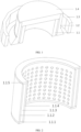
FIG. 1 is a schematic structural diagram of protective equipment of the present invention; -
FIG. 2 is a schematic structural diagram of an inner fence of the protective equipment; -
FIG. 3 is a schematic structural diagram of an outer fence of the protective equipment; -
FIG. 4 is a schematic structural diagram of a top cover of the protective equipment; -
FIG. 5 is a schematic structural diagram of an anti-leakage fence of the protective equipment; -
FIG. 6 is a schematic structural diagram of a protective system using the protective equipment of the present invention; -
FIG. 7 is a schematic structural diagram of a supporting frame of the protective system; and -
FIG. 8 is an enlarged diagram of a top of the supporting frame. - 1-protective equipment; 2-supporting frame; 3-water cannon; 1.1-inner fence; 1.2-outer fence; 1.3-anti-leakage fence; 1.4-top cover; 1.1.1-inner fence bottom supporting plate; 1.1.2-inner fence outer supporting layer; 1.1.3-anti-explosion decontamination liquid layer; 1.1.4-inner fence inner supporting layer; 1.1.5-inner fence top supporting plate; 1.2.1-outer fence bottom supporting plate; 1.2.2-outer fence kinetic energy absorption layer; 1.2.3-outer fence ammunition protection layer; 1.2.4-outer fence outer supporting layer; 1.2.5-outer fence top supporting plate; 1.2.6-outer fence bottom reinforcement layer; 1.2.7-shock wave bottom enhanced absorption layer; 1.3.1-shock wave absorption layer; 1.3.2-ammunition protection plate; 1.4.1-top cover supporting layer; 1.4.2-top cover explosion-proof decontamination liquid layer; 1.4.3-top ammunition protection layer; 1.4.4-top skin; 2.1-fixing base; 2.2-vertical rod; 2.3-supporting rod; 2.5-top sliding rod group; 2.5.1-transverse rod installation screw; 2.5.2-transverse rod; 2.5.3-top rod; 2.5.4-lateral sliding chute rod; and 2.5.5-lateral sliding chute rod fixing screw.
- The present invention is further described in detail below in combination with accompanying drawings.
- The present embodiment provides unexploded ammunition/explosive destruction protective equipment which uses a modularized assembled type structure, and can quickly dispose an explosive and unexploded military ammunition without causing secondary damage.
- As shown in
FIG. 1 , the unexploded ammunition/explosive destruction protective equipment includes four modules: an inner fence 1.1, an outer fence 1.2, an anti-leakage fence 1.3, and a top cover 1.4. The inner fence 1.1 and the outer fence 1.2 are each of a barrel-shaped structure with openings in two ends. The inner fence 1.1 is a straight barrel (with an equal diameter); the outer fence 1.2 includes a conical section and a straight barrel section connected with a small end of the conical section; the conical section is located below the straight barrel section; the inner fence 1.1 is coaxially arranged inside the outer fence 1.2 in a sleeving manner, and a gap is reserved between the inner fence 1.1 and the outer fence 1.2; the top cover 1.4 covers top openings of the inner fence 1.1 and the outer fence 1.2 to close the top openings of the inner fence 1.1 and the outer fence 1.2; the top cover 1.4 is provided with a through hole running through a space encircled by the inner fence 1.1; and a circle of anti-leakage fence 1.3 is arranged at the periphery of the outer fence 1.2. - As shown in
FIG. 2 , the inner fence 1.1 includes an inner fence bottom supporting plate 1.1.1, an inner fence outer supporting layer 1.1.2, an explosion-proof decontamination liquid layer 1.1.3, an inner fence inner supporting layer 1.1.4, and an inner fence top supporting plate 1.1.5. The inner fence 1.1 is of a three-layer structure, including the inner fence outer supporting layer 1.1.2, the explosion-proof decontamination liquid layer 1.1.3, and the inner fence inner supporting layer 1.1.4 in sequence from outside to inside. The ringlike inner fence top supporting plate 1.1.5 is arranged on a top axial end surface; and the ringlike inner fence bottom supporting plate 1.1.1 is arranged on a bottom axial end surface. That is, the inner fence outer supporting layer 1.1.2, the inner fence inner supporting layer 1.1.4, the inner fence bottom supporting plate 1.1.1, and the inner fence top supporting plate 1.1.5 encircle to form a barrel-shaped structure with an inner ringlike cavity (a ringlike cavity between the inner fence outer supporting layer 1.1.2 and the inner fence inner supporting layer 1.1.4). A package bag filled with explosion-proof decontamination liquid is installed in the ringlike cavity to form the explosion-proof decontamination liquid layer 1.1.3. Two axial ends of the inner fence outer supporting layer 1.1.2 and the inner fence inner supporting layer 1.1.4 are respectively adhered to the inner fence top supporting plate 1.1.5 and the inner fence bottom supporting plate 1.1.1 through epoxy resin glue. - The inner fence bottom supporting plate 1.1.1, the inner fence outer supporting layer 1.1.2, the inner fence inner supporting layer 1.1.4, and the inner fence top supporting plate 1.1.5 use polyurea sprayed with foam or other viscous-elastic materials; a plurality of pores are uniformly distributed in an inner circumferential surface of the inner fence inner supporting layer 1.1.4, and a pore area is 30%-70% of a total area of the inner circumferential surface to enable shock waves and liquid in the explosion-proof decontamination liquid layer 1.1.3 to be fully mixed, which is more favorable for reduction of the shock waves. The inner fence 1.1 is mainly structurally supported by the inner fence bottom supporting plate 1.1.1, the inner fence outer supporting layer 1.1.2 and the inner fence inner supporting layer 1.1.4. Constituents of the explosion-proof decontamination liquid include a liquid decontamination agent and water-absorbing resin. The type of the liquid decontamination agent can be added according to possible toxins of unexploded ammunition. For example, 2% hypochlorite, peroxyacetic acid, sodium carbonate and water (a mass fraction is 1: 12.5) are added, and the package bag filled with the explosion-proof decontamination liquid is made of a material that does not react with the explosion-proof decontamination liquid, such as a polytetrafluoroethylene package tape.
- As shown in
FIG. 3 , the outer fence 1.2 includes an outer fence bottom supporting plate 1.2.1, an outer fence kinetic energy absorption layer 1.2.2, an outer fence ammunition protection layer 1.2.3, an outer fence outer supporting layer 1.2.4, an outer fence top supporting plate 1.2.5, an outer fence bottom reinforcement layer 1.2.6 and a shock wave bottom enhanced absorption layer 1.2.7. The outer fence 1.2 is of a three-layer structure, including the outer fence kinetic energy absorption layer 1.2.2, the outer fence ammunition protection layer 1.2.3, and the outer fence outer supporting layer 1.2.4 in sequence from inside to outside; the ringlike outer fence top supporting plate 1.2.5 is arranged on a top axial end surface; and the ringlike outer fence bottom supporting plate 1.2.1 is arranged on a bottom axial end surface. The outer fence bottom supporting plate 1.2.1, the outer fence outer supporting layer 1.2.4 and the outer fence top supporting plate 1.2.5 are all supported by foam, and outer surfaces thereof are sprayed with polyurea or other viscous-elastic materials to achieve a supporting function; the adjacent outer fence kinetic energy absorption layer 1.2.2, the outer fence ammunition protection layer 1.2.3 and the outer fence outer supporting layer 1.2.4 are adhered to each other through epoxy resin glue; and two axial ends of the outer fence kinetic energy absorption layer 1.2.2, the outer fence ammunition protection layer 1.2.3 and the outer fence outer supporting layer 1.2.4 are respectively adhered to the outer fence top supporting plate 1.2.5 and the outer fence bottom supporting plate 1.2.1 through epoxy resin glue. - The outer fence kinetic energy absorption layer 1.2.2 realizes kinetic energy absorption and supporting by mainly using a polyurea sprayed PC plate; the outer fence ammunition protection layer 1.2.3 mainly plays an ammunition protection role, and is made of one of, or hybrid ammunition protection fiber selected from two or more of PE, aramid fiber, glass fiber, carbon fiber, or PBO fiber.
- The outer fence bottom reinforcement layer 1.2.6 and the shock wave bottom enhanced absorption layer 1.2.7 are arranged at the periphery of the bottom of the outer fence 1.2. Heights of the outer fence bottom reinforcement layer 1.2.6 and the shock wave bottom enhanced absorption layer 1.2.7 are about 1/4-1/2 of the whole height of the outer fence 1.2. An inner surface of the shock wave bottom enhanced absorption layer 1.2.7 is a circumferential surface, and an outer surface is a conical surface. The outer fence bottom reinforcement layer 1.2.6 is located between the shock wave bottom enhanced absorption layer 1.2.7 and the outer fence outer supporting layer 1.2.4. The outer fence bottom reinforcement layer 1.2.6 uses ammunition protection fiber with a thickness of 10 mm-20 mm, so that loading from post-explosion products on the fragments can be effectively prevented; the shock wave bottom enhanced absorption layer 1.2.7 is a package bag filled with the explosion-proof decontamination liquid, and includes the same constituents as the constituents of the explosion-proof decontamination liquid layer 1.1.3 in the inner fence 1.1; and a bottom shock wave pressure peak value can be effectively reduced by means of the shock wave bottom enhanced absorption layer 1.2.7.
- As shown in
FIG. 4 , the top cover 1.4 includes a top cover supporting layer 1.4.1, a top cover explosion-proof decontamination liquid layer 1.4.2 and a top ammunition protection layer 1.4.3; the top cover supporting layer 1.4.1 has a cavity inside; the top ammunition protection layer 1.4.3 and the top cover explosion-proof decontamination liquid layer 1.4.2 are arranged in the cavity in sequence from top to bottom, wherein the top cover explosion-proof decontamination liquid layer 1.4.2 is a package bag filled with explosion-proof decontamination liquid having the same constituents as the explosion-proof decontamination liquid layer 1.1.3 in the inner fence 1.1; the top ammunition protection layer 1.4.3 uses one of, or hybrid ammunition protection fiber selected from two or more of PE, aramid fiber, glass fiber, carbon fiber, or PBO fiber; the top cover supporting layer 1.4.1 is formed by spraying polyurea to polyurethane foam; and the top cover supporting layer 1.4.1 is packaged by oxford fabric. The through hole is reserved in the top cover 1.4, so that the water cannon launches a water flow to destruct the ammunition. That is, the through hole runs through the space encircled by the inner fence 1.1. In order to ensure the appearance of the structure, the through hole in the top of the top cover 1.4 is covered by a top skin 1.4.4; and a material of the top skin 1.4.4 is low-intensity cloth. - As shown in
FIG. 5 , the anti-leakage fence 1.3 is mainly used to prevent leakage of the fragments to play a protection enhanced role. The anti-leakage fence 1.3 is of a double-layer structure, including an inner-layer shock wave absorption layer 1.3.1 and an outer-layer ammunition protection plate 1.3.2. The inner-layer shock wave absorption layer 1.3.1 is used to absorb shock waves and uses polyurethane foam. Preferably, a density of the polyurethane foam is 50 kg/m3-200 kg/m3; the ammunition protection plate 1.3.2 uses a hard PE plate or an aramid plate; and the anti-leakage fence 1.3 has a height that is 1/3-1/2 of the height of the outer fence 1.2, and is foldable. During pressing of the PE plate or the aramid plate, bent parts are not pressed, so that the flexibility of the structure can be maintained, and convenient folding is achieved. - The embodiment provides an unexploded ammunition/explosive destruction system. As shown in
FIG. 6 , the unexploded ammunition/explosive destruction system includes theprotective equipment 1 in the above-mentionedembodiment 1, a supportingframe 2 and awater cannon 3. The type of thewater cannon 3 is commercially available. - The supporting
frame 2 uses a hollow steel pipe used to support and locate thewater cannon 3; thewater cannon 3 is supported and located above theprotective equipment 1 through the supportingframe 2, so that a launching opening of thewater cannon 3 extends into the inner fence 1.1 of theprotective equipment 1 from the through hole in the top cover 1.4 to destruct an unexploded ammunition/explosive placed in theprotective equipment 1 through the water cannon. - Since the
protective equipment 1 is separable, i.e., since theprotective equipment 1 is of a modularized assembled structure, during destruction of the unexploded ammunition/explosive, theprotective equipment 1 can be assembled directly in site without moving to the position of the unexploded ammunition/explosive, and the unexploded ammunition/explosive is placed inside the inner fence 1.1 of theprotective equipment 1; then, thewater cannon 3 is supported and located through the supportingframe 2; the launching opening of thewater cannon 3 can extend from the through hole in the top cover 1.4 into the inner fence 1.1 of theprotective equipment 1; and thewater cannon 3 is started to destruct the unexploded ammunition/explosive in theprotective equipment 1. - As shown in
FIG. 7 , the supportingframe 2 is of an inverted U-shaped structure, and includes fixing bases 2.1, vertical rods 2.2, supporting rods 2.3, and a top sliding rod group 2.5; two fixing bases 2.1 are respectively arranged on two sides of an opened end of the inverted U-shaped structure; the supportingframe 2 is fixed on the ground through the fixing bases 2.1; left and right ends of the top sliding rod group 2.5 are supported on the fixing bases 2.1 on the corresponding sides through two groups of parallel arc-shaped rods and two groups of parallel vertical rods 2.2; and two supporting rods 2.3 are arranged between the two parallel vertical rods 2.2 on the same side. - As shown in
FIG. 8 , the top sliding rod group 2.5 is of a rectangular structure, and includes two parallel transverse rods 2.5.2 and two parallel lateral sliding chute rods 2.5.4; the two transverse rods 2.5.2 and the two lateral sliding chute rods 2.5.4 are connected to form a rectangular structure; the lateral sliding chute rods 2.5.4 are provided with sliding chutes in length directions of the the lateral sliding chute rods 2.5.4; two parallel top rods 2.5.3 are mounted between the two lateral sliding chute rods 2.5.4; the two top rods 2.5.3 slide in the sliding chutes of the lateral sliding chute rods 2.5.4 to adjust a distance between the two top rods 2.5.3 (to adapt towater cannons 3 of different types and facilitate the installation of the water cannons 3); and after the desired distance is achieved through adjustment, the top rods 2.5.3 are fastened on the lateral sliding chute rods 2.5.4 through lateral sliding chute rod fixing screws 2.5.5. - A use process of the unexploded ammunition/explosive destruction system is as follows.
- After an unexploded ammunition is found, the unexploded ammunition is disposed according to the following mode.
-
- 1, the inner fence 1.1 is first lifted to cover the unexploded ammunition;
- 2, the outer fence 1.2 is lifted to sleeve the inner fence 1.1;
- 3, the top cover 1.4 is covered; and
- 4, the anti-leakage fence 1.3 is placed.
- Assembly of the supporting frame 2:
- 1, the vertical rods 2.2 are fixed on the fixing bases 2.1 through screws, and meanwhile, the supporting rods 2.3 are mounted on the vertical rods 2.2 through screws;
- 2, the top sliding rod group 2.5 is mounted on the vertical rods 2.2 through screws, and the position of the top sliding rod group 2.5 is adjusted in place;
- 3, the supporting
frame 2 is lifted to the unexploded ammunition; - 4, the fixing bases 2.1 are fixed on the ground through ground anchors, or a sand bag is lifted to press the fixing bases 2.1;
- 5, the
water cannon 3 is firmly fixed on the supportingframe 2 by twisting iron wires; and - 6, the launching opening of the
water cannon 3 is aligned with the fuse of the unexploded ammunition. -
- 1, the
water cannon 3 is remotely controlled to launch a high-velocity water flow to destruct the fuse of the unexploded ammunition; - 2, if the unexploded ammunition explodes at the moment, the
protective equipment 1 can prevent fragments from flying out, prevent shock waves from damaging the surroundings and avoid destruction of persons and property; and - 3, if the fuse of the unexploded ammunition is destructed at the moment, and the unexploded ammunition does not explode, the inside is seen by an X-ray machine to check the destruction state; and after the safety is ensured, the equipment can be stored for next use.
Claims (9)
- Explosive destruction protective equipment, characterized by comprising four modules: an inner fence (1.1), an outer fence (1.2), anti-leakage fence (1.3) and a top cover (1.4); an explosive being a waste military unexploded ammunition or civilian explosive; whereinthe inner fence (1.1) and the outer fence (1.2) are each of a barrel-shaped structure with openings in two ends, wherein the inner fence (1.1) is in a straight barrel shape, the outer fence (1.2) comprises a conical section and a straight barrel section connected with a small end of the conical section, and the conical section is located below the straight barrel section; the inner fence (1.1) is coaxially arranged inside the outer fence (1.2) in a sleeving manner, and a gap is reserved between the inner fence (1.1) and the outer fence (1.2); the top cover (1.4) covers top openings of the inner fence (1.1) and the outer fence (1.2) to close the top openings of the inner fence (1.1) and the outer fence (1.2); the top cover (1.4) is provided with a through hole running through a space encircled by the inner fence (1.1); the anti-leakage fence (1.3) is arranged at the periphery of the outer fence (1.2);the outer fence (1.2) comprises: an outer fence bottom supporting plate (1.2.1), an outer fence kinetic energy absorption layer (1.2.2), an outer fence ammunition protection layer (1.2.3), an outer fence outer supporting layer (1.2.4), an outer fence top supporting plate (1.2.5), an outer fence bottom reinforcement layer (1.2.6) and a shock wave bottom enhanced absorption layer (1.2.7);the outer fence (1.2) is of a three-layer structure, comprising the outer fence kinetic energy absorption layer (1.2.2), the outer fence ammunition protection layer (1.2.3), and the outer fence outer supporting layer (1.2.4) in sequence from inside to outside; the ringlike outer fence top supporting plate (1.2.5) is arranged on a top axial end surface of the outer fence (1.2); the ringlike outer fence bottom supporting plate (1.2.1) is arranged on a bottom axial end surface of the outer fence (1.2);the outer fence bottom reinforcement layer (1.2.6) and the shock wave bottom enhanced absorption layer (1.2.7) are arranged at the periphery of the bottom of the outer fence (1.2); an inner surface of the shock wave bottom enhanced absorption layer (1.2.7) is a circumferential surface, and an outer surface is a conical surface; the outer fence bottom reinforcement layer (1.2.6) is located between the shock wave bottom enhanced absorption layer (1.2.7) and the outer fence outer supporting layer (1.2.4); andthe outer fence bottom reinforcement layer (1.2.6) uses ammunition protection fiber, and the shock wave bottom enhanced absorption layer (1.2.7) is a package bag filled with explosion-proof decontamination liquid.
- The explosive destruction protective equipment according to claim 1, characterized in that a height of the anti-leakage fence (1.3) is 1/3-1/2 of a height of the outer fence (1.2).
- The explosive destruction protective equipment according to claim 1 or 2, characterized in that the inner fence (1.1) comprises: an inner fence bottom supporting plate (1.1.1), an inner fence outer supporting layer (1.1.2), an explosion-proof decontamination liquid layer (1.1.3), an inner fence inner supporting layer (1.1.4), and an inner fence top supporting plate (1.1.5);the inner fence (1.1) is of a three-layer structure, including the inner fence outer supporting layer (1.1.2), the explosion-proof decontamination liquid layer (1.1.3), and the inner fence inner supporting layer (1.1.4) in sequence from outside to inside; the ringlike inner fence top supporting plate (1.1.5) is arranged on a top axial end surface of the inner fence (1.1); the ringlike inner fence bottom supporting plate (1.1.1) is arranged on a bottom axial end surface of the inner fence (1.1); andtwo or more pores are uniformly formed in an inner circumferential surface of the inner fence inner supporting layer (1.1.4), and a pore area is 30%-70% of a total area of the inner circumferential surface.
- The explosive destruction protective equipment according to claim 1, characterized in that heights of the outer fence bottom reinforcement layer (1.2.6) and the shock wave bottom enhanced absorption layer (1.2.7) are 1/4-1/2 of the height of the outer fence (1.2).
- The explosive destruction protective equipment according to claim 1 or 2, characterized in that the top cover (1.4) comprises: a top cover supporting layer (1.4.1), a top cover explosion-proof decontamination liquid layer (1.4.2) and a top ammunition protection layer (1.4.3); and
the top cover supporting layer (1.4.1) has a cavity inside, and the top ammunition protection layer (1.4.3) and the top cover explosion-proof decontamination liquid layer (1.4.2) are arranged in the cavity in sequence from top to bottom, wherein the top cover explosion-proof decontamination liquid layer (1.4.2) is a package bag filled with explosion-proof decontamination liquid. - The explosive destruction protective equipment according to claim 1 or 2, characterized in that the anti-leakage fence (1.3) is of a double-layer structure, comprising an inner-layer shock wave absorption layer (1.3.1) and an outer-layer ammunition protection plate (1.3.2).
- The explosive destruction protective equipment according to claim 5, characterized in that a height of the anti-leakage fence (1.3) is 1/3-1/2 of the height of the outer fence (1.2).
- An explosive destruction system, characterized by comprising protective equipment (1), a supporting frame (2) and a water cannon (3); wherein the protective equipment (1) is the above-mentioned explosive destruction protective equipment according to any one of claims 1-7;the supporting frame (2) is used to support and locate the water cannon (3);the water cannon (3) is supported and located above the protective equipment (1) through the supporting frame (2), so that a launching opening of the water cannon (3) extends into an inner fence (1.1) of the protective equipment (1) from a through hole in a top cover (1.4) to destruct an explosive in the protective equipment (1).
- An explosive destruction method, characterized by using the explosive destruction system according to claim 8, wherein
after an explosive is found, the explosive is disposed according to the following mode:protection stage: firstly, covering an explosive by an inner fence (1.1); then, sleeving the outside of the inner fence (1.1) with an outer fence (1.2); covering a top cover (1.4); placing an anti-leakage fence (1.3);assembling a supporting frame (2);fixing a water cannon (3) on the supporting frame (2), and making an launching opening of the water cannon (3) extend into protective equipment (1) to enable the launching opening to be aligned with a fuse of the explosive; anddestruction: remotely controlling the water cannon (3) to launch a high-velocity water flow to destruct the fuse of the explosive; preventing fragments from flying out by the protective equipment (1) in the case that the explosive explodes at the moment, seeing the inside of the protective equipment (1) by an X-ray machine to check the destruction state of the explosive in the case that the fuse of the explosive is destructed and no explosion occurs, and storing the protective equipment (1), the supporting frame (2) and the water cannon (3) after the safety is ensured.
Applications Claiming Priority (2)
| Application Number | Priority Date | Filing Date | Title |
|---|---|---|---|
| CN202010542133 | 2020-06-15 | ||
| PCT/CN2021/098577 WO2021254191A1 (en) | 2020-06-15 | 2021-06-07 | Protection apparatus, system and method for destruction of explosives |
Publications (3)
| Publication Number | Publication Date |
|---|---|
| EP4166898A1 EP4166898A1 (en) | 2023-04-19 |
| EP4166898A4 EP4166898A4 (en) | 2024-06-19 |
| EP4166898B1 true EP4166898B1 (en) | 2025-05-07 |
Family
ID=73955645
Family Applications (1)
| Application Number | Title | Priority Date | Filing Date |
|---|---|---|---|
| EP21826606.2A Active EP4166898B1 (en) | 2020-06-15 | 2021-06-07 | Protection apparatus, system and method for destruction of explosives |
Country Status (4)
| Country | Link |
|---|---|
| US (1) | US11852451B2 (en) |
| EP (1) | EP4166898B1 (en) |
| CN (1) | CN112179231B (en) |
| WO (1) | WO2021254191A1 (en) |
Families Citing this family (14)
| Publication number | Priority date | Publication date | Assignee | Title |
|---|---|---|---|---|
| CN112179231B (en) * | 2020-06-15 | 2021-07-20 | 北京理工大学 | Explosive destruction protective equipment, system and method |
| CN112902780B (en) * | 2021-01-25 | 2024-09-13 | 西安物华巨能爆破器材有限责任公司 | Detonation destroying device for robot explosive removing system based on energy-gathering jet flow |
| CN113049419A (en) * | 2021-03-08 | 2021-06-29 | 中国人民解放军61699部队 | Performance test method of explosion-proof decontamination integrated disposal system |
| CN113446909B (en) * | 2021-06-29 | 2022-03-25 | 中国人民解放军国防科技大学 | Low-yield toxic explosive airbag recycling explosion-proof structure |
| CN113739660A (en) * | 2021-08-23 | 2021-12-03 | 北京理工大学 | Design and manufacturing method of folding type explosion-proof fence and product thereof |
| CN113932674B (en) * | 2021-09-24 | 2023-07-04 | 北京理工大学 | Method for enhancing explosion-proof performance of explosion-proof container |
| CN113954445B (en) * | 2021-10-22 | 2022-04-22 | 中国人民解放军93114部队 | Explosion-proof clothing and its fabric and preparation method |
| CN114485307B (en) * | 2022-01-29 | 2023-04-04 | 北京理工大学 | Intrinsically safe explosive disposal and protection device and use method |
| CN114636361B (en) * | 2022-02-15 | 2023-11-14 | 北京理工艾尔安全科技有限公司 | Soft fence type integrated explosion-proof blanket |
| CN114719703B (en) * | 2022-03-31 | 2023-02-21 | 北京理工大学 | Rigid-flexible composite structure airtight explosion-proof device |
| CN115307505B (en) * | 2022-08-09 | 2023-09-12 | 南京理工大学 | Underwater optical device protection structure applied to explosion pool |
| CN115540707B (en) * | 2022-09-16 | 2024-03-26 | 南京然之美信息科技有限公司 | Automatic laying trolley of explosion-proof blanket for station |
| CN115930716B (en) * | 2022-10-28 | 2024-10-15 | 山东非金属材料研究所 | A flexible explosion-proof tank and its manufacturing process |
| CN117663937A (en) * | 2023-12-29 | 2024-03-08 | 浙江省高能爆破工程有限公司 | A device and method for destroying waste ammunition |
Family Cites Families (30)
| Publication number | Priority date | Publication date | Assignee | Title |
|---|---|---|---|---|
| US3721201A (en) * | 1971-09-30 | 1973-03-20 | W Boller | Bomb recovery and shield apparatus |
| US3800715A (en) * | 1971-09-30 | 1974-04-02 | W Boller | Bomb recovery and shield apparatus |
| US4432285A (en) * | 1982-09-13 | 1984-02-21 | The United States Of America As Represented By The Secretary Of The Air Force | Bomb blast attenuator |
| GB2212702B (en) * | 1987-11-24 | 1991-06-05 | Michael Edward Cogger | A combined cattle crush and cattle pen |
| JPH0545100A (en) * | 1991-08-13 | 1993-02-23 | Nobel Kogyo Kk | Handling vessels for suspected articles, such as explosives |
| US6595247B1 (en) * | 2002-02-19 | 2003-07-22 | Jerome J. Landy | Suspicious object container and method |
| US7014059B2 (en) * | 2002-05-17 | 2006-03-21 | Master Lite Security Products, Inc. | Explosion resistant waste container |
| US6813986B1 (en) * | 2003-11-27 | 2004-11-09 | Counterterrorism Technologies Corporation | Reusable bomb diffuser |
| WO2005057126A1 (en) * | 2003-12-15 | 2005-06-23 | Long-Range Researches Center | Vodopad explosive ammunition impact containment device |
| US7490537B1 (en) * | 2004-08-13 | 2009-02-17 | Itt Manufacturing Enterprises, Inc. | Suppression apparatus for explosive devices |
| CN101149244B (en) * | 2006-09-18 | 2011-01-12 | 重庆金冠新技术开发有限公司 | Explosion-proof blanket |
| CN201093947Y (en) * | 2007-10-31 | 2008-07-30 | 周厚勇 | Explosion-proof blanket |
| US8413564B1 (en) * | 2009-09-29 | 2013-04-09 | The United States Of America As Represented By The Secretary Of The Army | Portable vented suppressive shield for protective tactical emplacement over suspected explosive devices |
| FR2959008B1 (en) * | 2010-04-16 | 2014-06-13 | Kairos | DEVICE FOR NEUTRALIZING RISK OBJECTS |
| US20130122269A1 (en) * | 2010-07-12 | 2013-05-16 | Lubrizol Advanced Materials, Inc. | High Temperature Exterior Building Products |
| US8839704B2 (en) * | 2011-05-31 | 2014-09-23 | Lawrence Livermore National Security, Llc. | Initiation disruptor systems and methods of initiation disruption |
| US20140323792A1 (en) * | 2013-04-25 | 2014-10-30 | Mp Associates, Inc. | Desensitizing explosive materials using a vacuum vessel |
| US11592269B2 (en) * | 2015-09-17 | 2023-02-28 | I P Creations Limited | Flash directed reactive target and method of manufacture |
| US10677575B2 (en) * | 2016-05-13 | 2020-06-09 | Captive Technologies, LLC | Single boundary layer optimized recalled airbag inflator container |
| CN205991752U (en) * | 2016-07-27 | 2017-03-01 | 北京中科盾科技有限公司 | A kind of shock wave guide housing explosion-proof blanket |
| CN106247860B (en) * | 2016-08-31 | 2018-02-09 | 江苏领瑞新材料科技有限公司 | A kind of fiber laid fabric high strength anti-explosion blanket |
| CN107314725B (en) * | 2017-06-23 | 2020-05-29 | 北京理工大学 | A variable wall thickness composite explosion-proof structure |
| KR101810983B1 (en) * | 2017-08-18 | 2017-12-26 | 대한민국 | Explosion Proof Block |
| CN109405695B (en) * | 2018-11-14 | 2024-02-20 | 北京理工大学 | An elastic composite structure with internal and external braces for flexible explosion-proofing |
| CN110579146B (en) * | 2019-09-17 | 2024-11-05 | 湖南艾尔防务技术有限公司 | An integrated explosion-proof blanket |
| CN110645863B (en) * | 2019-09-17 | 2024-08-09 | 北京理工大学 | A new explosion-proof blanket composite fence structure |
| CN111174657A (en) * | 2020-02-06 | 2020-05-19 | 北京理工大学 | A hollow annular flexible explosion-proof structure and design method thereof |
| CN112179231B (en) * | 2020-06-15 | 2021-07-20 | 北京理工大学 | Explosive destruction protective equipment, system and method |
| US11506465B1 (en) * | 2020-07-30 | 2022-11-22 | The United States Of America As Represented By The Secretary Of The Navy | Apparatus and methods for disrupting/disabling explosive ordnance |
| US11536549B1 (en) * | 2021-06-14 | 2022-12-27 | The United States Of America As Represented By The Secretary Of The Navy | Portable apparatus and method for disposing of explosive devices |
-
2020
- 2020-09-21 CN CN202010996417.3A patent/CN112179231B/en active Active
-
2021
- 2021-06-07 WO PCT/CN2021/098577 patent/WO2021254191A1/en not_active Ceased
- 2021-06-07 EP EP21826606.2A patent/EP4166898B1/en active Active
-
2022
- 2022-12-14 US US18/081,657 patent/US11852451B2/en active Active
Also Published As
| Publication number | Publication date |
|---|---|
| WO2021254191A1 (en) | 2021-12-23 |
| CN112179231B (en) | 2021-07-20 |
| US11852451B2 (en) | 2023-12-26 |
| CN112179231A (en) | 2021-01-05 |
| US20230184525A1 (en) | 2023-06-15 |
| EP4166898A1 (en) | 2023-04-19 |
| EP4166898A4 (en) | 2024-06-19 |
Similar Documents
| Publication | Publication Date | Title |
|---|---|---|
| US11852451B2 (en) | Protection equipment, system and method for destruction of explosives | |
| EP1036299B1 (en) | Apparatus and method for blast suppression | |
| EP0604589B1 (en) | Luggage container with reinforced walls for protection against bomb explosions | |
| KR920005345Y1 (en) | Storm guard | |
| EP0991449B1 (en) | Chemical biological explosive containment system | |
| FI97717C (en) | Tanks for use in aircraft for the protection of aircraft structures | |
| US6397753B2 (en) | Water-based apparatus to mitigate damage and injuries from a fully or partially confined explosion | |
| US20070119851A1 (en) | Bomb bin | |
| US20170045335A1 (en) | Blast resistant barrier and container | |
| CN113237400B (en) | Light-weight emergency disposal system for explosives/unexploded bombs | |
| CN111637808A (en) | Large-equivalent flexible composite explosion-proof equipment | |
| CN212227898U (en) | Large-equivalent flexible composite explosion-proof equipment | |
| CN114636361B (en) | Soft fence type integrated explosion-proof blanket | |
| CN112161521B (en) | Modular spliced explosion protection fence and explosion-proof blanket | |
| CN114485307B (en) | Intrinsically safe explosive disposal and protection device and use method | |
| CN114001610A (en) | Trapezoidal high polymer material composite flexible explosion-proof tank and preparation method thereof | |
| CN213021286U (en) | Flexible explosion-proof top cover of explosion-proof barrel | |
| US20060086735A1 (en) | Lightweight spherical blast resistant container | |
| CN216418112U (en) | Liquid nitrogen fire extinguishing bomb | |
| CN114776131A (en) | Anti-explosion tent of reconnaissance in field | |
| CN206192199U (en) | Explosive -removal container | |
| CN114234752A (en) | Cylindrical high polymer material composite flexible explosion-proof tank and preparation method thereof | |
| WO2005057126A1 (en) | Vodopad explosive ammunition impact containment device | |
| CN218864917U (en) | Flexible composite explosion-proof fence | |
| CN115628659A (en) | A flexible explosion-proof tank |
Legal Events
| Date | Code | Title | Description |
|---|---|---|---|
| STAA | Information on the status of an ep patent application or granted ep patent |
Free format text: STATUS: THE INTERNATIONAL PUBLICATION HAS BEEN MADE |
|
| PUAI | Public reference made under article 153(3) epc to a published international application that has entered the european phase |
Free format text: ORIGINAL CODE: 0009012 |
|
| STAA | Information on the status of an ep patent application or granted ep patent |
Free format text: STATUS: REQUEST FOR EXAMINATION WAS MADE |
|
| 17P | Request for examination filed |
Effective date: 20230116 |
|
| AK | Designated contracting states |
Kind code of ref document: A1 Designated state(s): AL AT BE BG CH CY CZ DE DK EE ES FI FR GB GR HR HU IE IS IT LI LT LU LV MC MK MT NL NO PL PT RO RS SE SI SK SM TR |
|
| DAV | Request for validation of the european patent (deleted) | ||
| DAX | Request for extension of the european patent (deleted) | ||
| A4 | Supplementary search report drawn up and despatched |
Effective date: 20240523 |
|
| RIC1 | Information provided on ipc code assigned before grant |
Ipc: F42D 5/045 20060101ALI20240516BHEP Ipc: F42D 5/04 20060101AFI20240516BHEP |
|
| GRAP | Despatch of communication of intention to grant a patent |
Free format text: ORIGINAL CODE: EPIDOSNIGR1 |
|
| STAA | Information on the status of an ep patent application or granted ep patent |
Free format text: STATUS: GRANT OF PATENT IS INTENDED |
|
| INTG | Intention to grant announced |
Effective date: 20241205 |
|
| GRAS | Grant fee paid |
Free format text: ORIGINAL CODE: EPIDOSNIGR3 |
|
| GRAA | (expected) grant |
Free format text: ORIGINAL CODE: 0009210 |
|
| STAA | Information on the status of an ep patent application or granted ep patent |
Free format text: STATUS: THE PATENT HAS BEEN GRANTED |
|
| AK | Designated contracting states |
Kind code of ref document: B1 Designated state(s): AL AT BE BG CH CY CZ DE DK EE ES FI FR GB GR HR HU IE IS IT LI LT LU LV MC MK MT NL NO PL PT RO RS SE SI SK SM TR |
|
| REG | Reference to a national code |
Ref country code: GB Ref legal event code: FG4D |
|
| REG | Reference to a national code |
Ref country code: CH Ref legal event code: EP |
|
| REG | Reference to a national code |
Ref country code: DE Ref legal event code: R096 Ref document number: 602021030561 Country of ref document: DE |
|
| REG | Reference to a national code |
Ref country code: IE Ref legal event code: FG4D |
|
| PGFP | Annual fee paid to national office [announced via postgrant information from national office to epo] |
Ref country code: AT Payment date: 20250721 Year of fee payment: 5 |
|
| REG | Reference to a national code |
Ref country code: NL Ref legal event code: MP Effective date: 20250507 |
|
| PG25 | Lapsed in a contracting state [announced via postgrant information from national office to epo] |
Ref country code: PT Free format text: LAPSE BECAUSE OF FAILURE TO SUBMIT A TRANSLATION OF THE DESCRIPTION OR TO PAY THE FEE WITHIN THE PRESCRIBED TIME-LIMIT Effective date: 20250908 Ref country code: FI Free format text: LAPSE BECAUSE OF FAILURE TO SUBMIT A TRANSLATION OF THE DESCRIPTION OR TO PAY THE FEE WITHIN THE PRESCRIBED TIME-LIMIT Effective date: 20250507 Ref country code: ES Free format text: LAPSE BECAUSE OF FAILURE TO SUBMIT A TRANSLATION OF THE DESCRIPTION OR TO PAY THE FEE WITHIN THE PRESCRIBED TIME-LIMIT Effective date: 20250507 |
|
| REG | Reference to a national code |
Ref country code: LT Ref legal event code: MG9D |
|
| PG25 | Lapsed in a contracting state [announced via postgrant information from national office to epo] |
Ref country code: NO Free format text: LAPSE BECAUSE OF FAILURE TO SUBMIT A TRANSLATION OF THE DESCRIPTION OR TO PAY THE FEE WITHIN THE PRESCRIBED TIME-LIMIT Effective date: 20250807 Ref country code: GR Free format text: LAPSE BECAUSE OF FAILURE TO SUBMIT A TRANSLATION OF THE DESCRIPTION OR TO PAY THE FEE WITHIN THE PRESCRIBED TIME-LIMIT Effective date: 20250808 |
|
| PG25 | Lapsed in a contracting state [announced via postgrant information from national office to epo] |
Ref country code: NL Free format text: LAPSE BECAUSE OF FAILURE TO SUBMIT A TRANSLATION OF THE DESCRIPTION OR TO PAY THE FEE WITHIN THE PRESCRIBED TIME-LIMIT Effective date: 20250507 Ref country code: PL Free format text: LAPSE BECAUSE OF FAILURE TO SUBMIT A TRANSLATION OF THE DESCRIPTION OR TO PAY THE FEE WITHIN THE PRESCRIBED TIME-LIMIT Effective date: 20250507 |
|
| REG | Reference to a national code |
Ref country code: AT Ref legal event code: MK05 Ref document number: 1792884 Country of ref document: AT Kind code of ref document: T Effective date: 20250507 |
|
| PG25 | Lapsed in a contracting state [announced via postgrant information from national office to epo] |
Ref country code: BG Free format text: LAPSE BECAUSE OF FAILURE TO SUBMIT A TRANSLATION OF THE DESCRIPTION OR TO PAY THE FEE WITHIN THE PRESCRIBED TIME-LIMIT Effective date: 20250507 |
|
| PG25 | Lapsed in a contracting state [announced via postgrant information from national office to epo] |
Ref country code: HR Free format text: LAPSE BECAUSE OF FAILURE TO SUBMIT A TRANSLATION OF THE DESCRIPTION OR TO PAY THE FEE WITHIN THE PRESCRIBED TIME-LIMIT Effective date: 20250507 |
|
| PG25 | Lapsed in a contracting state [announced via postgrant information from national office to epo] |
Ref country code: AT Free format text: LAPSE BECAUSE OF FAILURE TO SUBMIT A TRANSLATION OF THE DESCRIPTION OR TO PAY THE FEE WITHIN THE PRESCRIBED TIME-LIMIT Effective date: 20250507 |
|
| PG25 | Lapsed in a contracting state [announced via postgrant information from national office to epo] |
Ref country code: RS Free format text: LAPSE BECAUSE OF FAILURE TO SUBMIT A TRANSLATION OF THE DESCRIPTION OR TO PAY THE FEE WITHIN THE PRESCRIBED TIME-LIMIT Effective date: 20250807 |
|
| PG25 | Lapsed in a contracting state [announced via postgrant information from national office to epo] |
Ref country code: IS Free format text: LAPSE BECAUSE OF FAILURE TO SUBMIT A TRANSLATION OF THE DESCRIPTION OR TO PAY THE FEE WITHIN THE PRESCRIBED TIME-LIMIT Effective date: 20250907 |
|
| PG25 | Lapsed in a contracting state [announced via postgrant information from national office to epo] |
Ref country code: LV Free format text: LAPSE BECAUSE OF FAILURE TO SUBMIT A TRANSLATION OF THE DESCRIPTION OR TO PAY THE FEE WITHIN THE PRESCRIBED TIME-LIMIT Effective date: 20250507 |
|
| REG | Reference to a national code |
Ref country code: DE Ref legal event code: R119 Ref document number: 602021030561 Country of ref document: DE |
|
| PG25 | Lapsed in a contracting state [announced via postgrant information from national office to epo] |
Ref country code: SM Free format text: LAPSE BECAUSE OF FAILURE TO SUBMIT A TRANSLATION OF THE DESCRIPTION OR TO PAY THE FEE WITHIN THE PRESCRIBED TIME-LIMIT Effective date: 20250507 Ref country code: DK Free format text: LAPSE BECAUSE OF FAILURE TO SUBMIT A TRANSLATION OF THE DESCRIPTION OR TO PAY THE FEE WITHIN THE PRESCRIBED TIME-LIMIT Effective date: 20250507 |
|
| PG25 | Lapsed in a contracting state [announced via postgrant information from national office to epo] |
Ref country code: CZ Free format text: LAPSE BECAUSE OF FAILURE TO SUBMIT A TRANSLATION OF THE DESCRIPTION OR TO PAY THE FEE WITHIN THE PRESCRIBED TIME-LIMIT Effective date: 20250507 |
|
| PG25 | Lapsed in a contracting state [announced via postgrant information from national office to epo] |
Ref country code: EE Free format text: LAPSE BECAUSE OF FAILURE TO SUBMIT A TRANSLATION OF THE DESCRIPTION OR TO PAY THE FEE WITHIN THE PRESCRIBED TIME-LIMIT Effective date: 20250507 |
|
| PG25 | Lapsed in a contracting state [announced via postgrant information from national office to epo] |
Ref country code: SK Free format text: LAPSE BECAUSE OF FAILURE TO SUBMIT A TRANSLATION OF THE DESCRIPTION OR TO PAY THE FEE WITHIN THE PRESCRIBED TIME-LIMIT Effective date: 20250507 |
|
| REG | Reference to a national code |
Ref country code: CH Ref legal event code: H13 Free format text: ST27 STATUS EVENT CODE: U-0-0-H10-H13 (AS PROVIDED BY THE NATIONAL OFFICE) Effective date: 20260127 |
|
| PG25 | Lapsed in a contracting state [announced via postgrant information from national office to epo] |
Ref country code: IT Free format text: LAPSE BECAUSE OF FAILURE TO SUBMIT A TRANSLATION OF THE DESCRIPTION OR TO PAY THE FEE WITHIN THE PRESCRIBED TIME-LIMIT Effective date: 20250507 |
|
| PG25 | Lapsed in a contracting state [announced via postgrant information from national office to epo] |
Ref country code: RO Free format text: LAPSE BECAUSE OF FAILURE TO SUBMIT A TRANSLATION OF THE DESCRIPTION OR TO PAY THE FEE WITHIN THE PRESCRIBED TIME-LIMIT Effective date: 20250507 |
|
| PG25 | Lapsed in a contracting state [announced via postgrant information from national office to epo] |
Ref country code: LU Free format text: LAPSE BECAUSE OF NON-PAYMENT OF DUE FEES Effective date: 20250607 |
|
| PG25 | Lapsed in a contracting state [announced via postgrant information from national office to epo] |
Ref country code: MC Free format text: LAPSE BECAUSE OF FAILURE TO SUBMIT A TRANSLATION OF THE DESCRIPTION OR TO PAY THE FEE WITHIN THE PRESCRIBED TIME-LIMIT Effective date: 20250507 |
|
| REG | Reference to a national code |
Ref country code: BE Ref legal event code: MM Effective date: 20250630 |
|
| PLBE | No opposition filed within time limit |
Free format text: ORIGINAL CODE: 0009261 |
|
| STAA | Information on the status of an ep patent application or granted ep patent |
Free format text: STATUS: NO OPPOSITION FILED WITHIN TIME LIMIT |
|
| REG | Reference to a national code |
Ref country code: CH Ref legal event code: L10 Free format text: ST27 STATUS EVENT CODE: U-0-0-L10-L00 (AS PROVIDED BY THE NATIONAL OFFICE) Effective date: 20260318 |
|
| PG25 | Lapsed in a contracting state [announced via postgrant information from national office to epo] |
Ref country code: DE Free format text: LAPSE BECAUSE OF NON-PAYMENT OF DUE FEES Effective date: 20260101 Ref country code: IE Free format text: LAPSE BECAUSE OF NON-PAYMENT OF DUE FEES Effective date: 20250607 |
|
| 26N | No opposition filed |
Effective date: 20260210 |
|
| PG25 | Lapsed in a contracting state [announced via postgrant information from national office to epo] |
Ref country code: BE Free format text: LAPSE BECAUSE OF NON-PAYMENT OF DUE FEES Effective date: 20250630 |
|
| PG25 | Lapsed in a contracting state [announced via postgrant information from national office to epo] |
Ref country code: FR Free format text: LAPSE BECAUSE OF NON-PAYMENT OF DUE FEES Effective date: 20250707 |
|
| PG25 | Lapsed in a contracting state [announced via postgrant information from national office to epo] |
Ref country code: CH Free format text: LAPSE BECAUSE OF NON-PAYMENT OF DUE FEES Effective date: 20250630 |
|
| GBPC | Gb: european patent ceased through non-payment of renewal fee |
Effective date: 20250807 |