EP4166887A1 - A heat exchanger - Google Patents
A heat exchanger Download PDFInfo
- Publication number
- EP4166887A1 EP4166887A1 EP21202175.2A EP21202175A EP4166887A1 EP 4166887 A1 EP4166887 A1 EP 4166887A1 EP 21202175 A EP21202175 A EP 21202175A EP 4166887 A1 EP4166887 A1 EP 4166887A1
- Authority
- EP
- European Patent Office
- Prior art keywords
- fluid
- plates
- heat exchanger
- openings
- channel
- Prior art date
- Legal status (The legal status is an assumption and is not a legal conclusion. Google has not performed a legal analysis and makes no representation as to the accuracy of the status listed.)
- Pending
Links
Images


Classifications
-
- F—MECHANICAL ENGINEERING; LIGHTING; HEATING; WEAPONS; BLASTING
- F28—HEAT EXCHANGE IN GENERAL
- F28D—HEAT-EXCHANGE APPARATUS, NOT PROVIDED FOR IN ANOTHER SUBCLASS, IN WHICH THE HEAT-EXCHANGE MEDIA DO NOT COME INTO DIRECT CONTACT
- F28D9/00—Heat-exchange apparatus having stationary plate-like or laminated conduit assemblies for both heat-exchange media, the media being in contact with different sides of a conduit wall
- F28D9/0031—Heat-exchange apparatus having stationary plate-like or laminated conduit assemblies for both heat-exchange media, the media being in contact with different sides of a conduit wall the conduits for one heat-exchange medium being formed by paired plates touching each other
- F28D9/0043—Heat-exchange apparatus having stationary plate-like or laminated conduit assemblies for both heat-exchange media, the media being in contact with different sides of a conduit wall the conduits for one heat-exchange medium being formed by paired plates touching each other the plates having openings therein for circulation of at least one heat-exchange medium from one conduit to another
- F28D9/005—Heat-exchange apparatus having stationary plate-like or laminated conduit assemblies for both heat-exchange media, the media being in contact with different sides of a conduit wall the conduits for one heat-exchange medium being formed by paired plates touching each other the plates having openings therein for circulation of at least one heat-exchange medium from one conduit to another the plates having openings therein for both heat-exchange media
-
- F—MECHANICAL ENGINEERING; LIGHTING; HEATING; WEAPONS; BLASTING
- F25—REFRIGERATION OR COOLING; COMBINED HEATING AND REFRIGERATION SYSTEMS; HEAT PUMP SYSTEMS; MANUFACTURE OR STORAGE OF ICE; LIQUEFACTION SOLIDIFICATION OF GASES
- F25B—REFRIGERATION MACHINES, PLANTS OR SYSTEMS; COMBINED HEATING AND REFRIGERATION SYSTEMS; HEAT PUMP SYSTEMS
- F25B39/00—Evaporators; Condensers
- F25B39/04—Condensers
-
- F—MECHANICAL ENGINEERING; LIGHTING; HEATING; WEAPONS; BLASTING
- F28—HEAT EXCHANGE IN GENERAL
- F28F—DETAILS OF HEAT-EXCHANGE AND HEAT-TRANSFER APPARATUS, OF GENERAL APPLICATION
- F28F3/00—Plate-like or laminated elements; Assemblies of plate-like or laminated elements
- F28F3/02—Elements or assemblies thereof with means for increasing heat-transfer area, e.g. with fins, with recesses, with corrugations
- F28F3/04—Elements or assemblies thereof with means for increasing heat-transfer area, e.g. with fins, with recesses, with corrugations the means being integral with the element
- F28F3/042—Elements or assemblies thereof with means for increasing heat-transfer area, e.g. with fins, with recesses, with corrugations the means being integral with the element in the form of local deformations of the element
-
- F—MECHANICAL ENGINEERING; LIGHTING; HEATING; WEAPONS; BLASTING
- F28—HEAT EXCHANGE IN GENERAL
- F28F—DETAILS OF HEAT-EXCHANGE AND HEAT-TRANSFER APPARATUS, OF GENERAL APPLICATION
- F28F9/00—Casings; Header boxes; Auxiliary supports for elements; Auxiliary members within casings
- F28F9/02—Header boxes; End plates
- F28F9/0219—Arrangements for sealing end plates into casing or header box; Header box sub-elements
- F28F9/0221—Header boxes or end plates formed by stacked elements
-
- F—MECHANICAL ENGINEERING; LIGHTING; HEATING; WEAPONS; BLASTING
- F28—HEAT EXCHANGE IN GENERAL
- F28F—DETAILS OF HEAT-EXCHANGE AND HEAT-TRANSFER APPARATUS, OF GENERAL APPLICATION
- F28F9/00—Casings; Header boxes; Auxiliary supports for elements; Auxiliary members within casings
- F28F9/02—Header boxes; End plates
- F28F9/026—Header boxes; End plates with static flow control means, e.g. with means for uniformly distributing heat exchange media into conduits
- F28F9/0263—Header boxes; End plates with static flow control means, e.g. with means for uniformly distributing heat exchange media into conduits by varying the geometry or cross-section of header box
-
- F—MECHANICAL ENGINEERING; LIGHTING; HEATING; WEAPONS; BLASTING
- F28—HEAT EXCHANGE IN GENERAL
- F28F—DETAILS OF HEAT-EXCHANGE AND HEAT-TRANSFER APPARATUS, OF GENERAL APPLICATION
- F28F9/00—Casings; Header boxes; Auxiliary supports for elements; Auxiliary members within casings
- F28F9/02—Header boxes; End plates
- F28F9/026—Header boxes; End plates with static flow control means, e.g. with means for uniformly distributing heat exchange media into conduits
- F28F9/0265—Header boxes; End plates with static flow control means, e.g. with means for uniformly distributing heat exchange media into conduits by using guiding means or impingement means inside the header box
-
- F—MECHANICAL ENGINEERING; LIGHTING; HEATING; WEAPONS; BLASTING
- F28—HEAT EXCHANGE IN GENERAL
- F28F—DETAILS OF HEAT-EXCHANGE AND HEAT-TRANSFER APPARATUS, OF GENERAL APPLICATION
- F28F9/00—Casings; Header boxes; Auxiliary supports for elements; Auxiliary members within casings
- F28F9/02—Header boxes; End plates
- F28F9/026—Header boxes; End plates with static flow control means, e.g. with means for uniformly distributing heat exchange media into conduits
- F28F9/0282—Header boxes; End plates with static flow control means, e.g. with means for uniformly distributing heat exchange media into conduits by varying the geometry of conduit ends, e.g. by using inserts or attachments for modifying the pattern of flow at the conduit inlet or outlet
-
- F—MECHANICAL ENGINEERING; LIGHTING; HEATING; WEAPONS; BLASTING
- F25—REFRIGERATION OR COOLING; COMBINED HEATING AND REFRIGERATION SYSTEMS; HEAT PUMP SYSTEMS; MANUFACTURE OR STORAGE OF ICE; LIQUEFACTION SOLIDIFICATION OF GASES
- F25B—REFRIGERATION MACHINES, PLANTS OR SYSTEMS; COMBINED HEATING AND REFRIGERATION SYSTEMS; HEAT PUMP SYSTEMS
- F25B2339/00—Details of evaporators; Details of condensers
- F25B2339/04—Details of condensers
- F25B2339/044—Condensers with an integrated receiver
- F25B2339/0441—Condensers with an integrated receiver containing a drier or a filter
-
- F—MECHANICAL ENGINEERING; LIGHTING; HEATING; WEAPONS; BLASTING
- F28—HEAT EXCHANGE IN GENERAL
- F28D—HEAT-EXCHANGE APPARATUS, NOT PROVIDED FOR IN ANOTHER SUBCLASS, IN WHICH THE HEAT-EXCHANGE MEDIA DO NOT COME INTO DIRECT CONTACT
- F28D21/00—Heat-exchange apparatus not covered by any of the groups F28D1/00 - F28D20/00
- F28D2021/0019—Other heat exchangers for particular applications; Heat exchange systems not otherwise provided for
- F28D2021/0068—Other heat exchangers for particular applications; Heat exchange systems not otherwise provided for for refrigerant cycles
- F28D2021/007—Condensers
Definitions
- the present invention relates to a plate heat exchanger.
- the invention relates to collars of the plate heat exchanger which promote laminar fluid flow within the heat exchanger.
- a plate-type heat exchangers may include a plurality of plates stacked together to form two fluid channels.
- the two fluid channels are fluidically isolated from each other, yet thermal coupled with each other.
- adjacent plates of the stacked plates delimit the path for the fluid channels.
- Each plate may include openings for enabling fluid flow into the respective fluid channels.
- the openings provided in the stack of plates form conduits that transfers the fluid to the respective fluid channels. Further, the openings may include collars to fluidically connect the conduits with the respective fluid channels.
- the two fluid channels can be a refrigerant channel and a coolant channel.
- the collars may include a portion that protrudes from the plates in a direction parallel to the longitudinal axis of the plates.
- Such portion in the collars may cause detrimental change in fluid path between the conduit and the fluid channels.
- the fluid flowing between the conduit and the respective fluid channel may have detrimental change in its flow path, i.e., 90 0 change in fluid flow direction.
- Such change in direction flow between the conduits and the fluid channels may leads to high pressure drop of the fluid at an inlet area in the conduits.
- Such highpressure drop of the fluid may cause non-uniform fluid distribution in the fluid channels that leads to inefficient heat exchange between two fluid flowing in the heat exchanger.
- some elements or parameters may be indexed, such as a first element and a second element.
- this indexation is only meant to differentiate and name elements, which are similar but not identical. No idea of priority should be inferred from such indexation, as these terms may be switched without betraying the invention. Additionally, this indexation does not imply any order in mounting or use of the elements of the invention.
- an embodiment of the invention herein provides a heat exchanger for heat exchange between two fluids.
- the heat exchanger includes a stack of plates forming at least one first channel for a first fluid and at least one second channel for a second fluid.
- the plates includes openings forming conduits for enabling the flow of the first fluid and the second fluid in the first and second channels respectively.
- the openings further include collars configured to promote laminar fluid flow between the channels and the respective conduits.
- At least one collar is inclined in a direction opposite to the intended fluid flow direction in the respective conduits.
- At least one collar is inclined along the intended fluid flow direction in the respective conduits.
- the openings providing the first fluid to the first channel are defined on one end of the plates, and the openings receiving the first fluid from the first channel are defined on opposite end of the plates.
- the openings providing the first fluid flow into the first channel are defined on a same end of the plates.
- the openings providing the second fluid flow into the second channel are provided on a same end of the plates.
- the collars of the openings are inclined in a range of 30° to 60°, preferably 45 0 with respect to longitudinal axis "L" of the plates.
- the heat exchanger further includes at least one separation plate having at least one baffle, and the separation plate being located in between two plates to define two fluid flow paths for the first channel and the second channel.
- the heat exchanger further includes at least one cover plate provided in contact with the plates to encapsulate at least a portion of the plates.
- the cover plate includes cover-openings complementary to the openings formed on the plates.
- cover-openings in the cover plate are bent beyond the collars of the openings.
- the collars of the alternate plates are extended beyond the collars of the adjacent plates.
- the heat exchanger is configured for an operation as a condenser, the first fluid being a liquid coolant and the second fluid being a refrigerant.
- the plates include a corrugation on its surface. Further, at least a portion of the collar may protrude directly from the corrugation formed on the plates.
- plate heat exchanger having laminar fluid flow between fluid channels and openings defined in the heat exchanger.
- plate heat exchanger may include a stack of plates forming two fluid channels, one set of channels being a coolant channel and another set of channels being a refrigerant channel.
- the plates may include openings forming conduits for enabling fluid flow into the channels. Further, the conduits may be connected to respective fluid circuits for enabling fluid flow into the respective channels.
- the openings may include collars having at least a portion of the plates that is substantially perpendicular to the fluid flow direction in the openings. As a result, the fluid flow path between the conduits and the respective fluid channels is substantially changed, that increases pressure drop of the fluid at the conduits.
- the collars of the openings are inclined to promote laminar fluid flow between the conduits and the fluid channels.
- the collar of the openings providing the coolant flow into the fluid channels are inclined to promote laminar coolant flow between the conduits and respective channels.
- laminar flow is characterized by fluid particles following smooth paths in layers, with each layer moving smoothly past the adjacent layers with little or no mixing.
- pressure drop of the fluid is reduced and achieving effective heat exchange in the heat exchanger.
- efficiency of the cooling circuit of a vehicle, in which the heat exchanger is disposed is increase. Position and geometry of the inclination provided in the collars are explained with respect to forthcoming figures in the description.
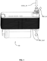
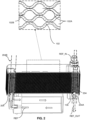
- Figs. 1 to 3 illustrate different views a heat exchanger 100, in accordance with an embodiment of the present invention.
- Fig. 1 shows a schematic view of the heat exchanger 100
- Figs. 2 and 3 show different cross-sectional views of the heat exchanger 100 of Fig. 1 .
- the heat exchanger 100 may be configured for heat exchange between a first fluid and a second fluid, for example, a refrigerant and a liquid coolant.
- the liquid coolant can be water or water-glycol mixture.
- the heat exchanger 100 is configured for an operation as a condenser, here the first fluid being a liquid coolant and the second fluid being a refrigerant.
- the heat exchanger 100 includes a plurality of plates 102 stacked together to form at least two fluid channels, namely, first channels 102A being liquid coolant channels and second channels 102B being refrigerant channels.
- the plates 102 are corrugated plates.
- the plates 102 may have corrugation on its surface.
- the first channels 102A and the second channels 102B are alternatively formed with each other by the plates 102.
- the plates 102 are stacked together so as to delimit one first channel 102A by a bottom surface of a first plate and a top surface of a second plate and to delimit one second channel 102B by a bottom surface of the second plate and a top surface of a third plate.
- the stack of plates 102 are brazed together without disturbing the fluid channels formed therein.
- at least a portion of the top surface of one plate is brazed to at least a portion of the bottom surface of the adjacent plate without disturbing the fluid flow path defined therein.
- the plates 102 may comprise openings 202, 204 forming conduits 202A-B, 204A-B to enable fluid flow in the first channels 102A and the second channels 102B.
- the openings 202, 204 may be classified into two sets of openings, a first set of openings 202 enabling the coolant circulation in the first channels 102A and a second set of openings 204 enabling the refrigerant circulation in the second channels 102B.
- the first set of openings 202 forming the first conduits 202A, 202B is to introduce and receive the coolant to/ from the first channels 102A respectively.
- the second set of openings 204 forming the second conduits 204A, 204B is to introduce and receive the refrigerant to/from the second channels 102B respectively.
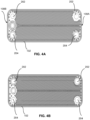
- the first set of openings 202 and the second set of openings 204 formed on the plates 102 are clearly shown in Figs. 4A and 4B .
- the openings 202, 204 may further comprise collars 302 configured to promote laminar fluid flow between the conduits 202A-B, 204A-B and the respective fluid channels 102A-B.
- the collars 302 provided in the first set of openings 202 may be configured to promote laminar flow of the first fluid between the first conduits 202A-B and the first channels 102A.
- the collars 302 provided in the second set of openings 204 are configured to promote laminar flow of the second fluid between the second conduits 204A-B and the second channels 102B.
- the collars 302 are defined in the plates 102 at the openings 106.
- the collars 302 may protrude directly from the corrugation formed on the plates 102.
- Figs. 4A and 4B illustrate top views of the two plates 102 of the heat exchanger 100 of Fig. 1 , depicting the first opening 202 and the second opening 204.
- the first set of openings 202 is formed on opposite ends of the plates 102.
- the first set of openings 202 providing the first fluid to the first channel 102A is formed on a first end 108A of the plates 102
- the first set of openings 202 receiving the first fluid from the first channels 102A is formed on a second end 108B of the plates 102.
- the second set of openings 202 is formed on opposite ends of the plates 102.
- the second set of openings 204 providing the second fluid to the second channel 102B is formed on the first end 108A of the plates 102, whereas the second set of openings 204 receiving the second fluid from the second channels 102B is formed on the second end 108B of the plates 102.
- first set of openings 202 providing the first fluid to the first channel 102A and the first set of openings 202 receiving the first fluid from the first channel 102A are formed on same end of the plates 102, i.e., either on the first end 108A or the second end 108B of the plates 102.
- second set of openings 204 enabling the second fluid circulation in the second channel 102B are formed on same end of the plates 102.
- each of the first channel 102A and the second channel 102B may require a partition plate to enable two-pass flow in the heat exchanger 100.
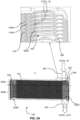
- Figs. 5A and 5B illustrate cross-sectional views of the heat exchanger 100 along the longitudinal axis "L" of the heat exchanger 100 of Fig. 1 depicting the first set of openings 202.
- Fig. 5C illustrates another cross-sectional view of the heat exchanger 100 along the longitudinal axis "L” of the heat exchanger 100 of Fig. 1 depicting the second set of openings 204.
- the collars 302 provided in the first set of openings 202 are referred to as first collars 302A and the collars 302 provided in the second set of openings 204 are referred to as second collars 302B.
- At least one collar amongst the first collars 302A is inclined in a direction opposite to the intended fluid flow direction in the respective first conduit 202A, as shown in the detailed view of Fig. 5A .
- the intended fluid flow direction means the direction of the first fluid flowing in the first conduit 202A
- the first conduits 202A, 202B is defined by the first set of openings 202.
- At least one collar amongst the first collars 302A is inclined along the intended fluid direction in the first conduit 202B, as shown in Fig. 5B .
- a set of first collars 302A is inclined in a direction opposite to the intended fluid flow direction in the respective conduits 202A, 202B and another set of first collars 302A is inclined along the intended fluid direction in the respective conduits 202A, 202B as shown in detailed view of Figs. 5A-B .
- the first collars 302A formed in the plates 102 at the first set of openings 202 are inclined between 30° and 60 0 , preferably 45 0 with respect to longitudinal axis "L" of the plates 102.
- the plate 102 as shown in Fig. 4A and the plate 102 as shown in Fig. 4B are alternatively arranged/stacked to form the heat exchanger 100.
- the first collars 302A of the alternate plates 102 is in contact with the adjacent collars, so as to close flow path of the second channels 102B, as shown in detailed view of the Fig. 5A .
- the first fluid, i.e., coolant, flowing in the first conduit 202A, 202B may not enter into the second channels 102B.
- the second collars 302B of the alternate plates 102 is in contact with the adjacent collars, so as to close flow path of the first channel 102A, as shown in the detailed view of Fig. 5C .
- the second fluid, i.e., refrigerant flowing in the second conduit 204A, 204B may not enter into the first channels 102A.
- the first collars 302A of the alternative plates are extended beyond the collars of adjacent plates as shown in Fig. 5A-B , so as to effectively close the first channel 102A at the second openings 204 and the second channel 102B at the first openings 202.
- the second collars 302B are not inclined collars, however it is possible to configure the second collars 302B as inclined collars.
- pressure of the refrigerant flowing into the second conduits 204A is higher, so the shape of the second collars 302A does not substantially change the pressure drop of the refrigerant at the second conduits 204A, 204B.
- the heat exchanger 100 includes a separation plate 306 located in between two plates 102 amongst the plurality of plates 102 to define two fluid flow paths for the first channels 102A and the second channels 102B.
- the separation plate 306 may include at least one baffle that enable fluid communication between two fluid paths.
- the first channels 102A are configured as a U-pass flow.
- the first fluid i.e., coolant may be introduced to the first conduit 202A through a coolant-inlet connector 402, and it is represented as COOL_IN in Fig. 5A .
- the first fluid may pass through the first channels 102A defined in a first coolant pass 308A and reaches the first channels 102A defined in the second coolant pass 308B through the first conduit 202B formed on other side of the plates 102A as shown in Fig. 5B .
- the separation plate 306 may include the baffle so that the first fluid may flow from the first coolant pass 308A of the first channel 102A to the second coolant pass 308B of the second channel 102B.
- the first fluid may exist from the second coolant pass 308B of the first channels 102A through the first conduit 202A and a coolant-outlet connector 404 as shown in Fig. 5B .
- introduction of the first fluid into the heat exchanger 100 is denoted as "COOL-IN” and reception of the first fluid from the heat exchanger 100 is denoted as "COOL_OUT”.
- COOL-IN introduction of the first fluid into the heat exchanger 100
- COOL_OUT reception of the first fluid from the heat exchanger 100
- the first collars 302A formed on the plates 102 at the first set of openings 202 are inclined, flow path of the first fluid between the first conduits 202A, 202B and the first channels 102A is not substantially changed, thereby eliminating pressure drop of the first fluid at the first conduit 202A.
- power consumed by a compressor provided in a coolant pump at the coolant circuit of the heat exchanger is reduced.
- the separation plate 306 may define two refrigerant flow paths for the second channels 102B.
- the second channels is defined as "U" pass flow and having two flow paths, namely a first refrigerant pass 310A and a second refrigerant pass 310B.
- the second fluid i.e.the refrigerant may enter into the second conduit 204A through a refrigerant-inlet connector 406 connected to the heat exchanger 100.
- the refrigerant-inlet connector 406 is in-line to the second openings 204 formed on the plates 102, so as introduce the second fluid to the second conduit 204A.
- the refrigerant-inlet connector 406 is in-line to the second conduit 204A. Thereafter, the second fluid may flow from the second conduit 204A formed in the first refrigerant pass 310A to the second conduit 204B through the second channel 102B.
- first channel 102A and the second channel 102B are in heat exchange configuration, so as to exchange heat between the first fluid and the second fluid.
- the second conduit 204B connected to the first refrigerant pass 310A may direct the second fluid to a receiver drier 312 for filtering process.
- the second fluid may flow back to the second conduit 204B connected to the second refrigerant pass 310B.
- the second fluid may flow from the second conduit 204B to the second conduit 204A through the second channel 102B formed in the second refrigerant pass 310B.
- the first channels 102A and the second channels 102B are in heat exchange configuration, so as to exchange heat between the first fluid and the second fluid.
- the second fluid may exit from the second refrigerant pass 310B through the second conduit 204A and may exit from the heat exchanger 100 through a refrigerant-outlet connector 408.
- the first collars 302A at the first set of openings 202 forming the first conduit 202A are inclined in a direction opposite to the intended fluid flow direction in the first conduit 202A.
- the first collars 302A promoting laminar first fluid flow between the first channel 102A in the first coolant pass 308A and the first conduit 202A.
- the first collars 302A at the first set of openings 202 forming the first conduit 202B in the first coolant pass 308A are inclined along the intended fluid flow direction in the first conduit 202B, thereby promoting laminar first fluid flow between the first channel 102A and the first conduit 202B.
- first collars 302A at the first set of openings 302A forming the first conduit 202B in the second coolant pass 308B are inclined in a direction opposite to the intended fluid flow direction in the first conduit 202B, thereby promoting laminar first fluid flow between the first conduit 202B and the first channel 102A in the second coolant pass 308B.
- first collars 302A at the first set of openings 302A forming the first conduit 202A in the second coolant pass 308B are inclined along the intended fluid flow direction in the first conduit 202A.
- the first collars 302 may promote laminar first fluid flow between the first channel 102A and the first conduit 202A in the second coolant pass 308B.
- the present example is U-pass coolant flow heat exchanger 100
- the first fluid may flow from either the first conduit 202A to first conduit 202B or vice-versa.
- the first fluid flowing into the heat exchanger 100 may not encounter substantial change in flow path, thereby maintaining uniform distribution of the first fluid across the first channels 102A in the heat exchanger.
- the pressure drop of the first fluid at the coolant inlet area is reduced and efficient heat exchange between the first fluid and the second fluid.
- the coolant pump is connected to the upstream of the coolant-inlet connector 402, so power consumed by the pump is reduced as there is not substantial pressure drop of the first fluid in the heat exchanger 100.
- the heat exchanger 100 further includes a pair of cover plates 502 provided in-contact with the plates 102 to encapsulate at least a portion of the plates 102.
- the plates 102 are sandwiched by the pair of cover plates 502.
- the cover plates 502 may include cover-openings 504 complementary to the first set of openings 202 and the second set of openings 204 as shown in Fig. 6 , so as enable fluid circulation in the respective conduits 202A, 204A.
- Fig. 6 illustrates schematic view of the cover plate 502 of the heat exchanger 100 of Fig. 1 .
- the inlet connectors 402, 406 and the outlet connectors 404, 408 are connected to the cover plate 502 at the respective cover-openings 504.
- the cover openings 504 are bent beyond the respective collars 302A, 302B of the respective openings 202, 204.
Landscapes
- Engineering & Computer Science (AREA)
- Physics & Mathematics (AREA)
- Thermal Sciences (AREA)
- Mechanical Engineering (AREA)
- General Engineering & Computer Science (AREA)
- Geometry (AREA)
- Heat-Exchange Devices With Radiators And Conduit Assemblies (AREA)
Abstract
Description
- The present invention relates to a plate heat exchanger. In particular, the invention relates to collars of the plate heat exchanger which promote laminar fluid flow within the heat exchanger.
- A plate-type heat exchangers may include a plurality of plates stacked together to form two fluid channels. The two fluid channels are fluidically isolated from each other, yet thermal coupled with each other. In one example, adjacent plates of the stacked plates delimit the path for the fluid channels. Each plate may include openings for enabling fluid flow into the respective fluid channels. The openings provided in the stack of plates form conduits that transfers the fluid to the respective fluid channels. Further, the openings may include collars to fluidically connect the conduits with the respective fluid channels. The two fluid channels can be a refrigerant channel and a coolant channel.
- Conventionally, the collars may include a portion that protrudes from the plates in a direction parallel to the longitudinal axis of the plates. Such portion in the collars may cause detrimental change in fluid path between the conduit and the fluid channels. For example, the fluid flowing between the conduit and the respective fluid channel may have detrimental change in its flow path, i.e., 900 change in fluid flow direction. Such change in direction flow between the conduits and the fluid channels may leads to high pressure drop of the fluid at an inlet area in the conduits. Such highpressure drop of the fluid may cause non-uniform fluid distribution in the fluid channels that leads to inefficient heat exchange between two fluid flowing in the heat exchanger. In case, pressure drop of the coolant is high at the inlet of the heat exchanger, the compressor provided in the coolant pump may consume more energy to pump the coolant to the heat exchanger. As a result, overall performance of the cooling circuit, in which the heat exchanger is provided, is affected.
- Accordingly, there remains a need for a heat exchanger that increases performance of the cooling circuit of a vehicle. Further, there remains another need for a simple design of collar defined on plates of a heat exchanger that reduces pressure drop at the inlet area of a heat exchanger. Yet, there remains another need for a collar that promotes laminar flow between an inlet and fluid channels of a heat exchanger. Furthermore, there remains another need for a plate heat exchanger that reduces power consumption by a compressor provided in a coolant pump disposed at upstream to the heat exchanger.
- In the present description, some elements or parameters may be indexed, such as a first element and a second element. In this case, unless stated otherwise, this indexation is only meant to differentiate and name elements, which are similar but not identical. No idea of priority should be inferred from such indexation, as these terms may be switched without betraying the invention. Additionally, this indexation does not imply any order in mounting or use of the elements of the invention.
- In view of the foregoing, an embodiment of the invention herein provides a heat exchanger for heat exchange between two fluids. The heat exchanger includes a stack of plates forming at least one first channel for a first fluid and at least one second channel for a second fluid. Further, the plates includes openings forming conduits for enabling the flow of the first fluid and the second fluid in the first and second channels respectively. The openings further include collars configured to promote laminar fluid flow between the channels and the respective conduits.
- In one embodiment, at least one collar is inclined in a direction opposite to the intended fluid flow direction in the respective conduits.
- In another embodiment, at least one collar is inclined along the intended fluid flow direction in the respective conduits.
- In one example, the openings providing the first fluid to the first channel are defined on one end of the plates, and the openings receiving the first fluid from the first channel are defined on opposite end of the plates.
- In another example, the openings providing the first fluid flow into the first channel are defined on a same end of the plates.
- Generally, the openings providing the second fluid flow into the second channel are provided on a same end of the plates.
- Further, the collars of the openings are inclined in a range of 30° to 60°, preferably 450 with respect to longitudinal axis "L" of the plates.
- In one example, the heat exchanger further includes at least one separation plate having at least one baffle, and the separation plate being located in between two plates to define two fluid flow paths for the first channel and the second channel.
- In another example, the heat exchanger further includes at least one cover plate provided in contact with the plates to encapsulate at least a portion of the plates. Further, the cover plate includes cover-openings complementary to the openings formed on the plates.
- Further, the cover-openings in the cover plate are bent beyond the collars of the openings.
- In one embodiment, the collars of the alternate plates are extended beyond the collars of the adjacent plates.
- Further, the heat exchanger is configured for an operation as a condenser, the first fluid being a liquid coolant and the second fluid being a refrigerant.
- In one example, the plates include a corrugation on its surface. Further, at least a portion of the collar may protrude directly from the corrugation formed on the plates.
- Other characteristics, details and advantages of the invention can be inferred from the description of the invention hereunder. A more complete appreciation of the invention and many of the attendant advantages thereof will be readily obtained as the same becomes better understood by reference to the following detailed description when considered in connection with the accompanying figures, wherein:
-
Fig. 1 illustrates a schematic view of the heat exchanger, in accordance with an embodiment of the present invention; -
Figs. 2 and3 illustrate cross-sectional views of the heat exchanger ofFig. 1 , showing fluid channels formed by a plurality of plates; -
Figs. 4A and 4B illustrate schematic views of the plates of the heat exchanger ofFig. 1 , depicting a first opening and a second opening; -
Figs. 5A and5B illustrate cross-sectional views of the heat exchanger along the longitudinal axis "L" of the heat exchanger ofFig. 1 depicting the first set of openings; -
Fig. 5C illustrates another cross-sectional view of the heat exchanger along the longitudinal axis "L" of the heat exchanger ofFig. 1 depicting the second set of openings; and -
Fig. 6 illustrates schematic view of the cover plate of the heat exchanger ofFig. 1 - It must be noted that the figures disclose the invention in a detailed enough way to be implemented, the figures helping to better define the invention. The invention should however not be limited to the embodiments disclosed in the description.
- The present invention relates to a plate heat exchanger having laminar fluid flow between fluid channels and openings defined in the heat exchanger. Generally, plate heat exchanger may include a stack of plates forming two fluid channels, one set of channels being a coolant channel and another set of channels being a refrigerant channel. The plates may include openings forming conduits for enabling fluid flow into the channels. Further, the conduits may be connected to respective fluid circuits for enabling fluid flow into the respective channels. The openings may include collars having at least a portion of the plates that is substantially perpendicular to the fluid flow direction in the openings. As a result, the fluid flow path between the conduits and the respective fluid channels is substantially changed, that increases pressure drop of the fluid at the conduits. Particularly, if the pressure drop at the coolant conduit increases, power consumption of a coolant pump provided at upstream to the heat exchanger is increased. As a result, performance of the system is affected and efficiency of the heat exchanger is reduced. To overcome such problems, the collars of the openings are inclined to promote laminar fluid flow between the conduits and the fluid channels. Particularly, the collar of the openings providing the coolant flow into the fluid channels are inclined to promote laminar coolant flow between the conduits and respective channels. In fluid dynamics, laminar flow is characterized by fluid particles following smooth paths in layers, with each layer moving smoothly past the adjacent layers with little or no mixing. As a result, pressure drop of the fluid is reduced and achieving effective heat exchange in the heat exchanger. Hence, efficiency of the cooling circuit of a vehicle, in which the heat exchanger is disposed, is increase. Position and geometry of the inclination provided in the collars are explained with respect to forthcoming figures in the description.
-
Figs. 1 to 3 illustrate different views aheat exchanger 100, in accordance with an embodiment of the present invention. Particularly,Fig. 1 shows a schematic view of theheat exchanger 100 andFigs. 2 and3 show different cross-sectional views of theheat exchanger 100 ofFig. 1 . Theheat exchanger 100 may be configured for heat exchange between a first fluid and a second fluid, for example, a refrigerant and a liquid coolant. The liquid coolant can be water or water-glycol mixture. In this example, theheat exchanger 100 is configured for an operation as a condenser, here the first fluid being a liquid coolant and the second fluid being a refrigerant. Theheat exchanger 100 includes a plurality ofplates 102 stacked together to form at least two fluid channels, namely,first channels 102A being liquid coolant channels andsecond channels 102B being refrigerant channels. In one embodiment, theplates 102 are corrugated plates. In another embodiment, theplates 102 may have corrugation on its surface. As shown in detailed view ofFig. 2 , thefirst channels 102A and thesecond channels 102B are alternatively formed with each other by theplates 102. In other words, theplates 102 are stacked together so as to delimit onefirst channel 102A by a bottom surface of a first plate and a top surface of a second plate and to delimit onesecond channel 102B by a bottom surface of the second plate and a top surface of a third plate. In one embodiment, the stack ofplates 102 are brazed together without disturbing the fluid channels formed therein. In one example, at least a portion of the top surface of one plate is brazed to at least a portion of the bottom surface of the adjacent plate without disturbing the fluid flow path defined therein. - Further, the
plates 102 may compriseopenings conduits 202A-B, 204A-B to enable fluid flow in thefirst channels 102A and thesecond channels 102B. Particularly, theopenings openings 202 enabling the coolant circulation in thefirst channels 102A and a second set ofopenings 204 enabling the refrigerant circulation in thesecond channels 102B. As shown inFig. 3 , the first set ofopenings 202 forming thefirst conduits first channels 102A respectively. As shown inFig. 2 , the second set ofopenings 204 forming thesecond conduits second channels 102B respectively. Further, the first set ofopenings 202 and the second set ofopenings 204 formed on theplates 102 are clearly shown inFigs. 4A and 4B . Theopenings collars 302 configured to promote laminar fluid flow between theconduits 202A-B, 204A-B and therespective fluid channels 102A-B. Particularly, thecollars 302 provided in the first set ofopenings 202 may be configured to promote laminar flow of the first fluid between thefirst conduits 202A-B and thefirst channels 102A. Further, thecollars 302 provided in the second set ofopenings 204 are configured to promote laminar flow of the second fluid between thesecond conduits 204A-B and thesecond channels 102B. Generally, thecollars 302 are defined in theplates 102 at theopenings 106. Particularly, thecollars 302 may protrude directly from the corrugation formed on theplates 102. -
Figs. 4A and 4B illustrate top views of the twoplates 102 of theheat exchanger 100 ofFig. 1 , depicting thefirst opening 202 and thesecond opening 204. In theplate 102 as shown inFig. 4A , the first set ofopenings 202 is formed on opposite ends of theplates 102. In other words, the first set ofopenings 202 providing the first fluid to thefirst channel 102A is formed on afirst end 108A of theplates 102, whereas the first set ofopenings 202 receiving the first fluid from thefirst channels 102A is formed on asecond end 108B of theplates 102. Similarly, the second set ofopenings 202 is formed on opposite ends of theplates 102. In other words, the second set ofopenings 204 providing the second fluid to thesecond channel 102B is formed on thefirst end 108A of theplates 102, whereas the second set ofopenings 204 receiving the second fluid from thesecond channels 102B is formed on thesecond end 108B of theplates 102. - In another embodiment, the first set of
openings 202 providing the first fluid to thefirst channel 102A and the first set ofopenings 202 receiving the first fluid from thefirst channel 102A are formed on same end of theplates 102, i.e., either on thefirst end 108A or thesecond end 108B of theplates 102. Similarly, the second set ofopenings 204 enabling the second fluid circulation in thesecond channel 102B are formed on same end of theplates 102. In such embodiment, each of thefirst channel 102A and thesecond channel 102B may require a partition plate to enable two-pass flow in theheat exchanger 100. The above-mentioned embodiment is not shown in any of the figures. -
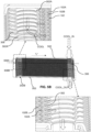
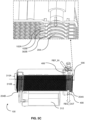
Figs. 5A and5B illustrate cross-sectional views of theheat exchanger 100 along the longitudinal axis "L" of theheat exchanger 100 ofFig. 1 depicting the first set ofopenings 202.Fig. 5C illustrates another cross-sectional view of theheat exchanger 100 along the longitudinal axis "L" of theheat exchanger 100 ofFig. 1 depicting the second set ofopenings 204. As explained above, thecollars 302 provided in the first set ofopenings 202 are referred to asfirst collars 302A and thecollars 302 provided in the second set ofopenings 204 are referred to assecond collars 302B. In one example, at least one collar amongst thefirst collars 302A is inclined in a direction opposite to the intended fluid flow direction in the respectivefirst conduit 202A, as shown in the detailed view ofFig. 5A . Here, the intended fluid flow direction means the direction of the first fluid flowing in thefirst conduit 202A, and thefirst conduits openings 202. - In another example, at least one collar amongst the
first collars 302A is inclined along the intended fluid direction in thefirst conduit 202B, as shown inFig. 5B . In yet another example, a set offirst collars 302A is inclined in a direction opposite to the intended fluid flow direction in therespective conduits first collars 302A is inclined along the intended fluid direction in therespective conduits Figs. 5A-B . In one embodiment, thefirst collars 302A formed in theplates 102 at the first set ofopenings 202 are inclined between 30° and 600, preferably 450 with respect to longitudinal axis "L" of theplates 102. - Further, the
plate 102 as shown inFig. 4A and theplate 102 as shown inFig. 4B are alternatively arranged/stacked to form theheat exchanger 100. Upon arranging theplates 102, at the first set ofopenings 202, thefirst collars 302A of thealternate plates 102 is in contact with the adjacent collars, so as to close flow path of thesecond channels 102B, as shown in detailed view of theFig. 5A . As a result, the first fluid, i.e., coolant, flowing in thefirst conduit second channels 102B. Similarly, at the second set ofopenings 204, thesecond collars 302B of thealternate plates 102 is in contact with the adjacent collars, so as to close flow path of thefirst channel 102A, as shown in the detailed view ofFig. 5C . As a result, the second fluid, i.e., refrigerant flowing in thesecond conduit first channels 102A. In this example, thefirst collars 302A of the alternative plates are extended beyond the collars of adjacent plates as shown inFig. 5A-B , so as to effectively close thefirst channel 102A at thesecond openings 204 and thesecond channel 102B at thefirst openings 202. - In the embodiment as shown in
Fig. 5C , thesecond collars 302B are not inclined collars, however it is possible to configure thesecond collars 302B as inclined collars. Generally, pressure of the refrigerant flowing into thesecond conduits 204A is higher, so the shape of thesecond collars 302A does not substantially change the pressure drop of the refrigerant at thesecond conduits second collars 302B as inclined collars to further decrease pressure drop of refrigerant and promote laminar fluid flow between thesecond conduits second channel 102B. - Further, the
heat exchanger 100 includes aseparation plate 306 located in between twoplates 102 amongst the plurality ofplates 102 to define two fluid flow paths for thefirst channels 102A and thesecond channels 102B. Theseparation plate 306 may include at least one baffle that enable fluid communication between two fluid paths. In this example as shown inFig. 5A , thefirst channels 102A are configured as a U-pass flow. Particularly, the first fluid, i.e., coolant may be introduced to thefirst conduit 202A through a coolant-inlet connector 402, and it is represented as COOL_IN inFig. 5A . Thereafter, the first fluid may pass through thefirst channels 102A defined in afirst coolant pass 308A and reaches thefirst channels 102A defined in thesecond coolant pass 308B through thefirst conduit 202B formed on other side of theplates 102A as shown inFig. 5B . Here, theseparation plate 306 may include the baffle so that the first fluid may flow from thefirst coolant pass 308A of thefirst channel 102A to thesecond coolant pass 308B of thesecond channel 102B. Thereafter, the first fluid may exist from thesecond coolant pass 308B of thefirst channels 102A through thefirst conduit 202A and a coolant-outlet connector 404 as shown inFig. 5B . Further, introduction of the first fluid into theheat exchanger 100 is denoted as "COOL-IN" and reception of the first fluid from theheat exchanger 100 is denoted as "COOL_OUT". As thefirst collars 302A formed on theplates 102 at the first set ofopenings 202 are inclined, flow path of the first fluid between thefirst conduits first channels 102A is not substantially changed, thereby eliminating pressure drop of the first fluid at thefirst conduit 202A. As a result, power consumed by a compressor provided in a coolant pump at the coolant circuit of the heat exchanger is reduced. - Similarly, the
separation plate 306 may define two refrigerant flow paths for thesecond channels 102B. In this example as shown inFig. 5C , the second channels is defined as "U" pass flow and having two flow paths, namely a firstrefrigerant pass 310A and a secondrefrigerant pass 310B. The second fluid, i.e.the refrigerant may enter into thesecond conduit 204A through a refrigerant-inlet connector 406 connected to theheat exchanger 100. The refrigerant-inlet connector 406 is in-line to thesecond openings 204 formed on theplates 102, so as introduce the second fluid to thesecond conduit 204A. In other words, the refrigerant-inlet connector 406 is in-line to thesecond conduit 204A. Thereafter, the second fluid may flow from thesecond conduit 204A formed in the firstrefrigerant pass 310A to thesecond conduit 204B through thesecond channel 102B. - Here, the
first channel 102A and thesecond channel 102B are in heat exchange configuration, so as to exchange heat between the first fluid and the second fluid. Thereafter, thesecond conduit 204B connected to the firstrefrigerant pass 310A may direct the second fluid to a receiver drier 312 for filtering process. Upon filtering, the second fluid may flow back to thesecond conduit 204B connected to the secondrefrigerant pass 310B. Thereafter, the second fluid may flow from thesecond conduit 204B to thesecond conduit 204A through thesecond channel 102B formed in the secondrefrigerant pass 310B. Here again, thefirst channels 102A and thesecond channels 102B are in heat exchange configuration, so as to exchange heat between the first fluid and the second fluid. Thereafter, the second fluid may exit from the secondrefrigerant pass 310B through thesecond conduit 204A and may exit from theheat exchanger 100 through a refrigerant-outlet connector 408. - In the example as shown in
Figs. 5A-C , thefirst collars 302A at the first set ofopenings 202 forming thefirst conduit 202A are inclined in a direction opposite to the intended fluid flow direction in thefirst conduit 202A. Hence, thefirst collars 302A promoting laminar first fluid flow between thefirst channel 102A in thefirst coolant pass 308A and thefirst conduit 202A. Further, thefirst collars 302A at the first set ofopenings 202 forming thefirst conduit 202B in thefirst coolant pass 308A are inclined along the intended fluid flow direction in thefirst conduit 202B, thereby promoting laminar first fluid flow between thefirst channel 102A and thefirst conduit 202B. - Further, the
first collars 302A at the first set ofopenings 302A forming thefirst conduit 202B in thesecond coolant pass 308B are inclined in a direction opposite to the intended fluid flow direction in thefirst conduit 202B, thereby promoting laminar first fluid flow between thefirst conduit 202B and thefirst channel 102A in thesecond coolant pass 308B. Similarly, thefirst collars 302A at the first set ofopenings 302A forming thefirst conduit 202A in thesecond coolant pass 308B are inclined along the intended fluid flow direction in thefirst conduit 202A. Hence, thefirst collars 302 may promote laminar first fluid flow between thefirst channel 102A and thefirst conduit 202A in thesecond coolant pass 308B. Although the present example is U-pass coolantflow heat exchanger 100, it is possible to implement same configuration of thefirst collars 302A in an "I-pass or single pass" coolantflow heat exchanger 100. In such case, the first fluid may flow from either thefirst conduit 202A tofirst conduit 202B or vice-versa. - As a result, the first fluid flowing into the
heat exchanger 100 may not encounter substantial change in flow path, thereby maintaining uniform distribution of the first fluid across thefirst channels 102A in the heat exchanger. As a result, the pressure drop of the first fluid at the coolant inlet area is reduced and efficient heat exchange between the first fluid and the second fluid. Further, the coolant pump is connected to the upstream of the coolant-inlet connector 402, so power consumed by the pump is reduced as there is not substantial pressure drop of the first fluid in theheat exchanger 100. - The
heat exchanger 100 further includes a pair ofcover plates 502 provided in-contact with theplates 102 to encapsulate at least a portion of theplates 102. In one example, theplates 102 are sandwiched by the pair ofcover plates 502. Thecover plates 502 may include cover-openings 504 complementary to the first set ofopenings 202 and the second set ofopenings 204 as shown inFig. 6 , so as enable fluid circulation in therespective conduits Fig. 6 illustrates schematic view of thecover plate 502 of theheat exchanger 100 ofFig. 1 . Theinlet connectors outlet connectors cover plate 502 at the respective cover-openings 504. In one example, thecover openings 504 are bent beyond therespective collars respective openings - In any case, the invention cannot and should not be limited to the embodiments specifically described in this document, as other embodiments might exist. The invention shall spread to any equivalent means and any technically operating combination of means.
Claims (14)
- A heat exchanger (100) for heat exchange between two fluids comprising: a stack of plates (102) forming at least one first channel (102A) for a first fluid and at least one second channel (102B) for a second fluid, the plates (102) comprising openings (202, 204) forming conduits (202A-B, 204A-B) for enabling the flow of the first fluid and the second fluid in the first and second channels (102A, 102B) respectively, wherein the openings (202, 204) comprise collars (302) configured to promote laminar fluid flow between the channels (102A, 102B) and the respective conduits (202A-B, 204A-B).
- The heat exchanger (100) according to claim 1, wherein at least one collar (302A) is inclined in a direction opposite to the intended fluid flow direction in the respective conduits (202A-B, 204A-B).
- The heat exchanger (100) according to claim 1, wherein at least one collar (302A) is inclined along the intended fluid flow direction in the respective conduits (202A-B, 204A-B).
- The heat exchanger (100) as claimed in any of the preceding claims, wherein the openings (202, 204) providing the first fluid to the first channel (102A) are defined on one end of the plates (108A), and the openings (202, 204) receiving the first fluid from the first channel (102A) are defined on opposite end of the plates (108B).
- The heat exchanger (100) according to any of the claims 1 to 3, wherein the openings (202, 204) providing the first fluid flow into the first channel (102A) are defined on a same end of the plates (108A or 108B).
- The heat exchanger (100) according to any of the preceding claims, wherein the openings (202, 204) providing the second fluid flow into the second channel (102B) are provided on a same end of the plates (108A or 108B).
- The heat exchanger (100) as claimed in any of the preceding claims, wherein the collars (302A) of the openings (202, 204) are inclined in a range of 300 to 600, preferably 450 with respect to longitudinal axis "L" of the plates (102).
- The heat exchanger (100) as claimed in any of the preceding claims, further comprising at least one separation plate (306) comprising at least one baffle, the separation plate (306) being located in between two plates (102to define two fluid flow paths (308A, 308B, 310A, 310B) for the first channel (102A) and the second channel (102B).
- The heat exchanger (100) as claimed in any of the preceding claims, further comprising at least one cover plate (502) provided in-contact with the plates (102) to encapsulate at least a portion of the plates (102), wherein the cover plate (502) further comprising cover-openings (504) complementary to the openings (202, 204) formed on the plates (102).
- The heat exchanger (100) as claimed in the claim 9, wherein the cover-openings (504) in the cover plate (502) are bent beyond the collars (302A) of the openings (202).
- The heat exchanger (100) as claimed in any of the preceding claims, wherein the collars (302A) of the alternate plates (102) are extended beyond the collars of the adjacent plates (102).
- The heat exchanger (100) as claimed in any of the preceding claims, wherein the heat exchanger (100) is configured for an operation as a condenser, the first fluid being a liquid coolant and the second fluid being a refrigerant.
- The heat exchanger (100) according to any of the preceding claims, wherein the plates (102) comprise a corrugation on its surface.
- The heat exchanger (100) according to the preceding claim, wherein at least a portion of the collar (302A, 302B) protrude directly from the corrugation formed on the plates (102).
Priority Applications (2)
| Application Number | Priority Date | Filing Date | Title |
|---|---|---|---|
| EP21202175.2A EP4166887A1 (en) | 2021-10-12 | 2021-10-12 | A heat exchanger |
| PCT/EP2022/078443 WO2023062101A1 (en) | 2021-10-12 | 2022-10-12 | A heat exchanger |
Applications Claiming Priority (1)
| Application Number | Priority Date | Filing Date | Title |
|---|---|---|---|
| EP21202175.2A EP4166887A1 (en) | 2021-10-12 | 2021-10-12 | A heat exchanger |
Publications (1)
| Publication Number | Publication Date |
|---|---|
| EP4166887A1 true EP4166887A1 (en) | 2023-04-19 |
Family
ID=78087302
Family Applications (1)
| Application Number | Title | Priority Date | Filing Date |
|---|---|---|---|
| EP21202175.2A Pending EP4166887A1 (en) | 2021-10-12 | 2021-10-12 | A heat exchanger |
Country Status (2)
| Country | Link |
|---|---|
| EP (1) | EP4166887A1 (en) |
| WO (1) | WO2023062101A1 (en) |
Cited By (2)
| Publication number | Priority date | Publication date | Assignee | Title |
|---|---|---|---|---|
| EP4553436A1 (en) * | 2023-11-08 | 2025-05-14 | Valeo Systemes Thermiques | A heat exchanger |
| EP4553437A1 (en) * | 2023-11-08 | 2025-05-14 | Valeo Systemes Thermiques | A heat exchanger |
Citations (6)
| Publication number | Priority date | Publication date | Assignee | Title |
|---|---|---|---|---|
| US6340054B1 (en) * | 1999-08-19 | 2002-01-22 | Behr Gmbh & Co. | Plate heat exchanger |
| US20020066552A1 (en) * | 2000-11-29 | 2002-06-06 | Shuji Komoda | Heat exchanger of aluminum |
| US20020084059A1 (en) * | 2000-12-14 | 2002-07-04 | Herbert Rittberger | Heat exchanger |
| KR20090013703A (en) * | 2007-08-02 | 2009-02-05 | 가부시키가이샤 덴소 | Laminated Plate Heat Exchanger |
| US20150292803A1 (en) * | 2012-11-07 | 2015-10-15 | Alfa Laval Corporate Ab | Method of making a plate package for a plate heat exchanger |
| FR3059400A1 (en) * | 2016-11-25 | 2018-06-01 | Valeo Systemes Thermiques | HEAT EXCHANGER BETWEEN A REFRIGERANT FLUID AND A COOLANT LIQUID |
-
2021
- 2021-10-12 EP EP21202175.2A patent/EP4166887A1/en active Pending
-
2022
- 2022-10-12 WO PCT/EP2022/078443 patent/WO2023062101A1/en not_active Ceased
Patent Citations (6)
| Publication number | Priority date | Publication date | Assignee | Title |
|---|---|---|---|---|
| US6340054B1 (en) * | 1999-08-19 | 2002-01-22 | Behr Gmbh & Co. | Plate heat exchanger |
| US20020066552A1 (en) * | 2000-11-29 | 2002-06-06 | Shuji Komoda | Heat exchanger of aluminum |
| US20020084059A1 (en) * | 2000-12-14 | 2002-07-04 | Herbert Rittberger | Heat exchanger |
| KR20090013703A (en) * | 2007-08-02 | 2009-02-05 | 가부시키가이샤 덴소 | Laminated Plate Heat Exchanger |
| US20150292803A1 (en) * | 2012-11-07 | 2015-10-15 | Alfa Laval Corporate Ab | Method of making a plate package for a plate heat exchanger |
| FR3059400A1 (en) * | 2016-11-25 | 2018-06-01 | Valeo Systemes Thermiques | HEAT EXCHANGER BETWEEN A REFRIGERANT FLUID AND A COOLANT LIQUID |
Cited By (3)
| Publication number | Priority date | Publication date | Assignee | Title |
|---|---|---|---|---|
| EP4553436A1 (en) * | 2023-11-08 | 2025-05-14 | Valeo Systemes Thermiques | A heat exchanger |
| EP4553437A1 (en) * | 2023-11-08 | 2025-05-14 | Valeo Systemes Thermiques | A heat exchanger |
| WO2025099043A1 (en) * | 2023-11-08 | 2025-05-15 | Valeo Systemes Thermiques | A heat exchanger |
Also Published As
| Publication number | Publication date |
|---|---|
| WO2023062101A1 (en) | 2023-04-20 |
Similar Documents
| Publication | Publication Date | Title |
|---|---|---|
| US11976894B2 (en) | High-performance heat exchanger with calibrated bypass | |
| US11254236B2 (en) | High performance uniform temperature cold plate | |
| KR100365996B1 (en) | Heat exchanger | |
| US9267740B2 (en) | Manifold fluid communication plate | |
| EP2172730B1 (en) | Plate laminate type heat exchanger | |
| JP4101174B2 (en) | Heat exchanger | |
| EP3872435B1 (en) | A heat exchanger | |
| WO2023062101A1 (en) | A heat exchanger | |
| CN113825966A (en) | Temperature control devices, especially cooling devices for motor vehicles | |
| CN117858438A (en) | Heat Exchanger | |
| CN216432588U (en) | Thermal regulation device | |
| JP2002164490A (en) | Stack cooler | |
| EP3546257B1 (en) | Air conditioning system for buses | |
| US12460879B2 (en) | Heat exchanger | |
| JP7683025B2 (en) | Cooler including two substantially parallel flow chambers and three substantially parallel plates | |
| KR20250018553A (en) | Power battery heat exchanger, power battery system and electric vehicle | |
| CN115135950A (en) | Heat exchanger | |
| EP4148366A1 (en) | A heat exchanger | |
| JP7696756B2 (en) | Surface contact heat exchanger | |
| EP4023996A1 (en) | Heat exchanger | |
| EP4023995A1 (en) | Heat exchanger | |
| CN119123858A (en) | Plate heat exchanger, use of a plate heat exchanger in a refrigerant circuit and use of a plate heat exchanger as an integrated gas cooler in a refrigerant compressor | |
| JP2025171264A (en) | heat exchanger | |
| KR20240077129A (en) | Plate type heat exchanger having branch type flow path | |
| CN119231015A (en) | Inter-cell cooling unit for battery module and battery module for motor vehicle |
Legal Events
| Date | Code | Title | Description |
|---|---|---|---|
| PUAI | Public reference made under article 153(3) epc to a published international application that has entered the european phase |
Free format text: ORIGINAL CODE: 0009012 |
|
| STAA | Information on the status of an ep patent application or granted ep patent |
Free format text: STATUS: THE APPLICATION HAS BEEN PUBLISHED |
|
| AK | Designated contracting states |
Kind code of ref document: A1 Designated state(s): AL AT BE BG CH CY CZ DE DK EE ES FI FR GB GR HR HU IE IS IT LI LT LU LV MC MK MT NL NO PL PT RO RS SE SI SK SM TR |
|
| STAA | Information on the status of an ep patent application or granted ep patent |
Free format text: STATUS: REQUEST FOR EXAMINATION WAS MADE |
|
| 17P | Request for examination filed |
Effective date: 20231019 |
|
| RBV | Designated contracting states (corrected) |
Designated state(s): AL AT BE BG CH CY CZ DE DK EE ES FI FR GB GR HR HU IE IS IT LI LT LU LV MC MK MT NL NO PL PT RO RS SE SI SK SM TR |
|
| STAA | Information on the status of an ep patent application or granted ep patent |
Free format text: STATUS: EXAMINATION IS IN PROGRESS |
|
| 17Q | First examination report despatched |
Effective date: 20250409 |