EP4166849A1 - Pyrolytic cleaning of combustors - Google Patents
Pyrolytic cleaning of combustors Download PDFInfo
- Publication number
- EP4166849A1 EP4166849A1 EP22200918.5A EP22200918A EP4166849A1 EP 4166849 A1 EP4166849 A1 EP 4166849A1 EP 22200918 A EP22200918 A EP 22200918A EP 4166849 A1 EP4166849 A1 EP 4166849A1
- Authority
- EP
- European Patent Office
- Prior art keywords
- combustor
- recited
- interior surfaces
- flame
- gas turbine
- Prior art date
- Legal status (The legal status is an assumption and is not a legal conclusion. Google has not performed a legal analysis and makes no representation as to the accuracy of the status listed.)
- Withdrawn
Links
- 238000004140 cleaning Methods 0.000 title claims description 9
- 239000000446 fuel Substances 0.000 claims abstract description 35
- 238000002485 combustion reaction Methods 0.000 claims abstract description 29
- 238000000034 method Methods 0.000 claims abstract description 27
- OKTJSMMVPCPJKN-UHFFFAOYSA-N Carbon Chemical compound [C] OKTJSMMVPCPJKN-UHFFFAOYSA-N 0.000 claims abstract description 21
- 229910052799 carbon Inorganic materials 0.000 claims abstract description 21
- 238000010438 heat treatment Methods 0.000 claims abstract description 12
- 238000011144 upstream manufacturing Methods 0.000 claims description 4
- 230000010006 flight Effects 0.000 claims description 3
- 239000007789 gas Substances 0.000 description 19
- 238000012423 maintenance Methods 0.000 description 5
- 238000004891 communication Methods 0.000 description 3
- 230000003628 erosive effect Effects 0.000 description 3
- 239000012530 fluid Substances 0.000 description 2
- QVGXLLKOCUKJST-UHFFFAOYSA-N atomic oxygen Chemical compound [O] QVGXLLKOCUKJST-UHFFFAOYSA-N 0.000 description 1
- 238000007796 conventional method Methods 0.000 description 1
- 238000000151 deposition Methods 0.000 description 1
- 230000008021 deposition Effects 0.000 description 1
- 230000000694 effects Effects 0.000 description 1
- 238000002347 injection Methods 0.000 description 1
- 239000007924 injection Substances 0.000 description 1
- 238000002955 isolation Methods 0.000 description 1
- 239000000203 mixture Substances 0.000 description 1
- 238000012986 modification Methods 0.000 description 1
- 230000004048 modification Effects 0.000 description 1
- 230000010355 oscillation Effects 0.000 description 1
- 229910052760 oxygen Inorganic materials 0.000 description 1
- 239000001301 oxygen Substances 0.000 description 1
- 239000000243 solution Substances 0.000 description 1
Images

Classifications
-
- F—MECHANICAL ENGINEERING; LIGHTING; HEATING; WEAPONS; BLASTING
- F23—COMBUSTION APPARATUS; COMBUSTION PROCESSES
- F23R—GENERATING COMBUSTION PRODUCTS OF HIGH PRESSURE OR HIGH VELOCITY, e.g. GAS-TURBINE COMBUSTION CHAMBERS
- F23R3/00—Continuous combustion chambers using liquid or gaseous fuel
- F23R3/28—Continuous combustion chambers using liquid or gaseous fuel characterised by the fuel supply
- F23R3/34—Feeding into different combustion zones
- F23R3/343—Pilot flames, i.e. fuel nozzles or injectors using only a very small proportion of the total fuel to insure continuous combustion
-
- F—MECHANICAL ENGINEERING; LIGHTING; HEATING; WEAPONS; BLASTING
- F01—MACHINES OR ENGINES IN GENERAL; ENGINE PLANTS IN GENERAL; STEAM ENGINES
- F01D—NON-POSITIVE DISPLACEMENT MACHINES OR ENGINES, e.g. STEAM TURBINES
- F01D25/00—Component parts, details, or accessories, not provided for in, or of interest apart from, other groups
- F01D25/002—Cleaning of turbomachines
-
- F—MECHANICAL ENGINEERING; LIGHTING; HEATING; WEAPONS; BLASTING
- F01—MACHINES OR ENGINES IN GENERAL; ENGINE PLANTS IN GENERAL; STEAM ENGINES
- F01D—NON-POSITIVE DISPLACEMENT MACHINES OR ENGINES, e.g. STEAM TURBINES
- F01D5/00—Blades; Blade-carrying members; Heating, heat-insulating, cooling or antivibration means on the blades or the members
- F01D5/005—Repairing methods or devices
-
- F—MECHANICAL ENGINEERING; LIGHTING; HEATING; WEAPONS; BLASTING
- F02—COMBUSTION ENGINES; HOT-GAS OR COMBUSTION-PRODUCT ENGINE PLANTS
- F02C—GAS-TURBINE PLANTS; AIR INTAKES FOR JET-PROPULSION PLANTS; CONTROLLING FUEL SUPPLY IN AIR-BREATHING JET-PROPULSION PLANTS
- F02C7/00—Features, components parts, details or accessories, not provided for in, or of interest apart form groups F02C1/00 - F02C6/00; Air intakes for jet-propulsion plants
- F02C7/26—Starting; Ignition
- F02C7/264—Ignition
-
- F—MECHANICAL ENGINEERING; LIGHTING; HEATING; WEAPONS; BLASTING
- F05—INDEXING SCHEMES RELATING TO ENGINES OR PUMPS IN VARIOUS SUBCLASSES OF CLASSES F01-F04
- F05D—INDEXING SCHEME FOR ASPECTS RELATING TO NON-POSITIVE-DISPLACEMENT MACHINES OR ENGINES, GAS-TURBINES OR JET-PROPULSION PLANTS
- F05D2220/00—Application
- F05D2220/30—Application in turbines
- F05D2220/32—Application in turbines in gas turbines
- F05D2220/323—Application in turbines in gas turbines for aircraft propulsion, e.g. jet engines
-
- F—MECHANICAL ENGINEERING; LIGHTING; HEATING; WEAPONS; BLASTING
- F05—INDEXING SCHEMES RELATING TO ENGINES OR PUMPS IN VARIOUS SUBCLASSES OF CLASSES F01-F04
- F05D—INDEXING SCHEME FOR ASPECTS RELATING TO NON-POSITIVE-DISPLACEMENT MACHINES OR ENGINES, GAS-TURBINES OR JET-PROPULSION PLANTS
- F05D2240/00—Components
- F05D2240/35—Combustors or associated equipment
-
- F—MECHANICAL ENGINEERING; LIGHTING; HEATING; WEAPONS; BLASTING
- F05—INDEXING SCHEMES RELATING TO ENGINES OR PUMPS IN VARIOUS SUBCLASSES OF CLASSES F01-F04
- F05D—INDEXING SCHEME FOR ASPECTS RELATING TO NON-POSITIVE-DISPLACEMENT MACHINES OR ENGINES, GAS-TURBINES OR JET-PROPULSION PLANTS
- F05D2260/00—Function
- F05D2260/60—Fluid transfer
- F05D2260/607—Preventing clogging or obstruction of flow paths by dirt, dust, or foreign particles
-
- F—MECHANICAL ENGINEERING; LIGHTING; HEATING; WEAPONS; BLASTING
- F23—COMBUSTION APPARATUS; COMBUSTION PROCESSES
- F23R—GENERATING COMBUSTION PRODUCTS OF HIGH PRESSURE OR HIGH VELOCITY, e.g. GAS-TURBINE COMBUSTION CHAMBERS
- F23R2900/00—Special features of, or arrangements for continuous combustion chambers; Combustion processes therefor
- F23R2900/00019—Repairing or maintaining combustion chamber liners or subparts
Definitions
- the present disclosure relates to continuous ignition systems, and more particularly to torch ignitors for lighting and relighting gas turbine engines.
- Carbon growth can occur in gas turbine engine combustors in which excess fuel accumulates on surfaces, and there is not enough oxygen and/or heat present to burn the fuel.
- This fuel can solidify on components (such as fuel injectors or the combustor liner) which if left unchecked could prevent proper operation of the device. For example, if it were not periodically maintained, the fuel nozzle could become plugged so that it no longer functions and this would cause uneven temperature distribution within the combustor. This could deteriorate performance and damage components within the hot section of the engine. To prevent these effects, routine maintenance must be performed to clean carbon build up out of the combustion components. Additionally, if left unchecked carbon deposits can break off during operation which can cause erosion of components within the hot section of the engine. Life of the fuel injector can be limited due to carbon buildup, so after a time the injector must be replaced or cleaned, and can determine the maintenance cycle. These are factors also limit how long an engine can remain on wing between when major maintenance is required.
- a method of operating a torch ignitor for continuous ignition includes issuing a flame from a combustion chamber of a torch ignitor into a combustor of a gas turbine engine while the gas turbine engine is not issuing fuel through fuel injectors into the combustor.
- the method includes heating interior surfaces of the combustor with the flame, wherein heat from the flame reacts with carbon deposits on the interior surfaces to remove the carbon deposits.
- the torch ignitor can be aboard an aircraft. Issuing flame and heating the interior surfaces can be performed as a cleaning cycle between flights of the aircraft.
- the cleaning cycle can include issuing air from a compressed air source outside the combustor into the combustor for use in pyrolyzing the carbon deposits.
- the compressed air source can include at least one of a compressor of the gas turbine engine, a shop air source external to the gas turbine engine, and/or a fan. Air can be channeled from the compressed air source into the combustion chamber of the torch ignitor.
- Issuing the flame from the combustion chamber of the torch ignitor can be performed while maintaining the combustor and the fuel injectors assembled within the gas turbine engine. Maintaining the combustor and the fuel injectors assembled within the gas turbine engine can include maintaining the gas turbine engine assembled on an airframe.
- Issuing the flame and heating interior surfaces can be performed for a period of time sufficient to remove carbon build up on the interior surfaces built up since a previous cycle of issuing the flame and heating interior surfaces.
- the interior surfaces can include at least one surface inside the fuel injectors, at least one surface on an exterior of the fuel injectors, at least one inside surface of an upstream combustor dome wall of the combustor, at least one surface of a radially outward facing wall of the combustor downstream of a combustor dome wall, and/or at least one surface of a radially inward facing wall of the combustor downstream of a combustor dome wall.
- Fig. 1 a partial view of an embodiment of a system in accordance with the disclosure is shown in Fig. 1 and is designated generally by reference character 100.
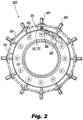
- Fig. 2 Other embodiments of systems in accordance with the disclosure, or aspects thereof, are provided in Fig. 2 as will be described.
- the systems and methods described herein can be used to reduce and/or remove carbon deposits from surfaces of combustors in gas turbine engines.
- the torch ignitor system 100 includes a torch ignitor 101 having a torch wall 102.
- the torch wall 102 defines a combustion chamber 104 therein with a flame outlet 106 passing out of the torch wall 102 downstream of the combustion chamber 104.
- a fuel nozzle 108 is mounted to the torch wall 102 to issue fuel into the combustion chamber 104.
- At least one ignitor 110 is mounted to the torch wall 102, positioned to ignite fuel issued from the fuel nozzle 108.
- An exhaust or outlet tube 112 is in fluid communication with the combustion chamber 104 extending downstream from the combustion chamber to the flame outlet 106.
- the torch wall 102 is mounted to an engine case 114 of a gas turbine engine, e.g. aboard an aircraft schematically indicated with reference character 10.
- a combustor 116 is included within the engine case 114, e.g. for receiving compressor discharge air from an upstream compressor (not shown but the diffuser 118 of the compressor is labeled in Fig. 1 ), combusting fuel in the compressor discharge air, and issuing combustion products to a downstream turbine, the inlet 119 of which is labeled in Fig. 1 .
- the flame outlet 106 is mounted in fluid communication, through outlet tube 112, with an interior combustion space 120 of the combustor 116.
- the combustor 116 is spaced apart from the combustion chamber 104 of the torch wall 102, so at start up or in the event of a flame out in the main combustion space 120, a flame 105 from the combustion chamber 104 can issue through the outlet tube 112 and into the combustion space 120 to light or relight the combustor 116.
- the torch combustion chamber 104 is mostly isolated from the main combustor 116.
- the narrow outlet tube 112 acts as an isolator which limits communication between the two volumes. This isolation allows the torch combustion chamber 104 to be stable while the main combustor 116 could have strong pressure oscillations which happen during ignition, blowout, acoustic instabilities, and the like.
- the torch combustion chamber 104 is also generally sheltered from the main combustor flow field so recirculation patterns, high velocity zones, and the like do not make their way up into the torch combustion chamber 104.
- a mounting flange 122 extends from the torch wall 102 and is mounted to the engine case 114.
- the ignitors 110 extend from outside the torch wall 102 and into the combustion chamber 104 for igniting a mixture of fuel and air from the fuel nozzle 108 to start up the torch ignitor system 100.
- the torch ignitor 101 is in addition to a plurality of main fuel injectors 109 extending through the case 114 and connecting to the combustor 116 for injection of fuel and air into the combustion space 120.
- An elbow 113 of the tube 112 of the torch ignitor 101 orients the outlet 106 tangential to the axial direction A, to issue the flame 105 tangentially across a portion of the annulus of the combustion space 120 as shown in Fig. 2 .
- a method includes issuing a flame 105 from the combustion chamber 104 of the torch ignitor 101 into the combustor 120 while the gas turbine engine is not issuing fuel through fuel injectors 109 into the combustor 116.
- the method includes heating interior surfaces 124, 126, 128, 132, 136 of the combustor 116 with the flame 105. Heat from the flame 105 reacts with carbon deposits on the interior surfaces 124, 126, 128, 132, 136 to remove carbon depositions which may have accumulated on these interior surfaces 124, 126, 128, 132, 136 during operation or shutdown of the engine.
- the cleaning cycle includes issuing air from a compressed air source outside the combustor 116 into the combustor 116 for use in pyrolyzing the carbon deposits.
- the compressed air source can include a compressor of the gas turbine engine (e.g. where air is fed through the diffusor 118 while the compressor is turned by an electrical motor or the like). It is also contemplated that the compressed air source can be a fan or shop air source 12 external to the gas turbine engine. Air is channeled from the compressed air source into the combustion chamber 104 of the torch ignitor 101.
- Issuing the flame 105 from the combustion chamber 104 of the torch ignitor 101 is performed while maintaining the combustor 116 and the fuel injectors 109 assembled within the gas turbine engine.
- Maintaining the combustor 116 and the fuel injectors 109 assembled within the gas turbine engine includes maintaining the gas turbine engine assembled on an airframe of the aircraft 10, e.g. on wing.
- Issuing the flame 105 and heating interior surfaces 124, 126, 128, 132, 136 is performed for a period of time sufficient to remove carbon build up on the interior surfaces 124, 126, 128, 132, 136 built up since a previous cleaning cycle.
- the interior surfaces 124, 126, 128, 132, 136 can include at least one surface 124 inside the fuel injectors 109, at least one surface 126 on an exterior of the fuel injectors 109, at least one inside surface 128 of an upstream combustor dome wall 130 of the combustor 116, at least one surface 132 of a radially outward facing wall 134 of the combustor 116 downstream of a combustor dome wall 130, and/or at least one surface 136 of a radially inward facing wall 138 of the combustor 116 downstream of a combustor dome wall 130.
Landscapes
- Engineering & Computer Science (AREA)
- Chemical & Material Sciences (AREA)
- Combustion & Propulsion (AREA)
- Mechanical Engineering (AREA)
- General Engineering & Computer Science (AREA)
- Fuel-Injection Apparatus (AREA)
Abstract
Description
- The present disclosure relates to continuous ignition systems, and more particularly to torch ignitors for lighting and relighting gas turbine engines.
- Carbon growth can occur in gas turbine engine combustors in which excess fuel accumulates on surfaces, and there is not enough oxygen and/or heat present to burn the fuel. This fuel can solidify on components (such as fuel injectors or the combustor liner) which if left unchecked could prevent proper operation of the device. For example, if it were not periodically maintained, the fuel nozzle could become plugged so that it no longer functions and this would cause uneven temperature distribution within the combustor. This could deteriorate performance and damage components within the hot section of the engine. To prevent these effects, routine maintenance must be performed to clean carbon build up out of the combustion components. Additionally, if left unchecked carbon deposits can break off during operation which can cause erosion of components within the hot section of the engine. Life of the fuel injector can be limited due to carbon buildup, so after a time the injector must be replaced or cleaned, and can determine the maintenance cycle. These are factors also limit how long an engine can remain on wing between when major maintenance is required.
- The conventional techniques have been considered satisfactory for their intended purpose. However, there is an ongoing need to increase how long engines can remain on-wing as well as to extend the maintenance interval of the engine. There is also an ongoing need to reduce erosion and damage that may occur between maintenance cycles. This disclosure provides a solution for these needs.
- A method of operating a torch ignitor for continuous ignition includes issuing a flame from a combustion chamber of a torch ignitor into a combustor of a gas turbine engine while the gas turbine engine is not issuing fuel through fuel injectors into the combustor. The method includes heating interior surfaces of the combustor with the flame, wherein heat from the flame reacts with carbon deposits on the interior surfaces to remove the carbon deposits.
- The torch ignitor can be aboard an aircraft. Issuing flame and heating the interior surfaces can be performed as a cleaning cycle between flights of the aircraft. The cleaning cycle can include issuing air from a compressed air source outside the combustor into the combustor for use in pyrolyzing the carbon deposits. The compressed air source can include at least one of a compressor of the gas turbine engine, a shop air source external to the gas turbine engine, and/or a fan. Air can be channeled from the compressed air source into the combustion chamber of the torch ignitor.
- Issuing the flame from the combustion chamber of the torch ignitor can be performed while maintaining the combustor and the fuel injectors assembled within the gas turbine engine. Maintaining the combustor and the fuel injectors assembled within the gas turbine engine can include maintaining the gas turbine engine assembled on an airframe.
- Issuing the flame and heating interior surfaces can be performed for a period of time sufficient to remove carbon build up on the interior surfaces built up since a previous cycle of issuing the flame and heating interior surfaces. The interior surfaces can include at least one surface inside the fuel injectors, at least one surface on an exterior of the fuel injectors, at least one inside surface of an upstream combustor dome wall of the combustor, at least one surface of a radially outward facing wall of the combustor downstream of a combustor dome wall, and/or at least one surface of a radially inward facing wall of the combustor downstream of a combustor dome wall.
- These and other features of the systems and methods of the subject disclosure will become more readily apparent to those skilled in the art from the following detailed description of the preferred embodiments taken in conjunction with the drawings.
- So that those skilled in the art to which the subject disclosure appertains will readily understand how to make and use the devices and methods of the subject disclosure without undue experimentation, preferred embodiments thereof will be described in detail herein below with reference to certain figures, wherein:
-
Fig. 1 is a schematic cross-sectional side elevation view of an embodiment of a system constructed in accordance with the present disclosure, showing the torch ignitor installed in a gas turbine engine for continuous ignition; and -
Fig. 2 is a schematic cross-sectional downstream end elevation view of the torch ignitor ofFig. 1 , showing the flame issuing from the torch ignitor for removing carbon deposits. - Reference will now be made to the drawings wherein like reference numerals identify similar structural features or aspects of the subject disclosure. For purposes of explanation and illustration, and not limitation, a partial view of an embodiment of a system in accordance with the disclosure is shown in
Fig. 1 and is designated generally byreference character 100. Other embodiments of systems in accordance with the disclosure, or aspects thereof, are provided inFig. 2 as will be described. The systems and methods described herein can be used to reduce and/or remove carbon deposits from surfaces of combustors in gas turbine engines. - The
torch ignitor system 100 includes atorch ignitor 101 having atorch wall 102. Thetorch wall 102 defines acombustion chamber 104 therein with aflame outlet 106 passing out of thetorch wall 102 downstream of thecombustion chamber 104. Afuel nozzle 108 is mounted to thetorch wall 102 to issue fuel into thecombustion chamber 104. At least oneignitor 110 is mounted to thetorch wall 102, positioned to ignite fuel issued from thefuel nozzle 108. An exhaust or outlet tube 112 is in fluid communication with thecombustion chamber 104 extending downstream from the combustion chamber to theflame outlet 106. - The
torch wall 102 is mounted to anengine case 114 of a gas turbine engine, e.g. aboard an aircraft schematically indicated withreference character 10. Acombustor 116 is included within theengine case 114, e.g. for receiving compressor discharge air from an upstream compressor (not shown but thediffuser 118 of the compressor is labeled inFig. 1 ), combusting fuel in the compressor discharge air, and issuing combustion products to a downstream turbine, theinlet 119 of which is labeled inFig. 1 . Theflame outlet 106 is mounted in fluid communication, through outlet tube 112, with aninterior combustion space 120 of thecombustor 116. Thecombustor 116 is spaced apart from thecombustion chamber 104 of thetorch wall 102, so at start up or in the event of a flame out in themain combustion space 120, aflame 105 from thecombustion chamber 104 can issue through the outlet tube 112 and into thecombustion space 120 to light or relight thecombustor 116. - The
torch combustion chamber 104 is mostly isolated from themain combustor 116. The narrow outlet tube 112 acts as an isolator which limits communication between the two volumes. This isolation allows thetorch combustion chamber 104 to be stable while themain combustor 116 could have strong pressure oscillations which happen during ignition, blowout, acoustic instabilities, and the like. Thetorch combustion chamber 104 is also generally sheltered from the main combustor flow field so recirculation patterns, high velocity zones, and the like do not make their way up into thetorch combustion chamber 104. - A
mounting flange 122 extends from thetorch wall 102 and is mounted to theengine case 114. Theignitors 110 extend from outside thetorch wall 102 and into thecombustion chamber 104 for igniting a mixture of fuel and air from thefuel nozzle 108 to start up thetorch ignitor system 100. Thetorch ignitor 101 is in addition to a plurality ofmain fuel injectors 109 extending through thecase 114 and connecting to thecombustor 116 for injection of fuel and air into thecombustion space 120. An elbow 113 of the tube 112 of thetorch ignitor 101 orients theoutlet 106 tangential to the axial direction A, to issue theflame 105 tangentially across a portion of the annulus of thecombustion space 120 as shown inFig. 2 . - With continued reference to
Fig. 1 , a method includes issuing aflame 105 from thecombustion chamber 104 of thetorch ignitor 101 into thecombustor 120 while the gas turbine engine is not issuing fuel throughfuel injectors 109 into thecombustor 116. The method includes heatinginterior surfaces combustor 116 with theflame 105. Heat from theflame 105 reacts with carbon deposits on theinterior surfaces interior surfaces - Issuing flame and heating the
interior surfaces aircraft 10. The cleaning cycle includes issuing air from a compressed air source outside thecombustor 116 into thecombustor 116 for use in pyrolyzing the carbon deposits. The compressed air source can include a compressor of the gas turbine engine (e.g. where air is fed through thediffusor 118 while the compressor is turned by an electrical motor or the like). It is also contemplated that the compressed air source can be a fan or shop air source 12 external to the gas turbine engine. Air is channeled from the compressed air source into thecombustion chamber 104 of thetorch ignitor 101. - Issuing the
flame 105 from thecombustion chamber 104 of thetorch ignitor 101 is performed while maintaining thecombustor 116 and thefuel injectors 109 assembled within the gas turbine engine. Maintaining thecombustor 116 and thefuel injectors 109 assembled within the gas turbine engine includes maintaining the gas turbine engine assembled on an airframe of theaircraft 10, e.g. on wing. - Issuing the
flame 105 and heatinginterior surfaces interior surfaces surface 124 inside thefuel injectors 109, at least onesurface 126 on an exterior of thefuel injectors 109, at least one inside surface 128 of an upstream combustor dome wall 130 of thecombustor 116, at least one surface 132 of a radially outward facing wall 134 of thecombustor 116 downstream of a combustor dome wall 130, and/or at least one surface 136 of a radially inward facing wall 138 of thecombustor 116 downstream of a combustor dome wall 130. - Potential benefits of systems and methods as disclosed herein include cleaning cycles that allow the torch system to remain on wing longer and prevents erosion of downstream components. The methods and systems of the present disclosure, as described above and shown in the drawings, provide for reducing and/or removing carbon deposits from surfaces of combustors in gas turbine engines. While the apparatus and methods of the subject disclosure have been shown and described with reference to preferred embodiments, those skilled in the art will readily appreciate that changes and/or modifications may be made thereto without departing from the scope of the invention as defined by the claims.
Claims (15)
- A method of operating a torch ignitor for continuous ignition comprising:issuing a flame (105) from a combustion chamber (104) of a torch ignitor (101) into a combustor of a gas turbine engine while the gas turbine engine is not issuing fuel through fuel injectors into the combustor (116); andheating interior surfaces of the combustor with the flame, wherein heat from the flame reacts with carbon deposits on the interior surfaces to remove the carbon deposits.
- The method as recited in claim 1, wherein the torch ignitor is aboard an aircraft and wherein issuing flame and heating the interior surfaces are performed as a cleaning cycle between flights of the aircraft.
- The method as recited in claim 2, wherein the cleaning cycle includes issuing air from a compressed air source outside the combustor into the combustor for use in pyrolyzing the carbon deposits.
- The method as recited in claim 3, wherein the compressed air source includes a compressor of the gas turbine engine.
- The method as recited in claim 3, wherein the compressed air source includes a shop air source (12) external to the gas turbine engine.
- The method as recited in claim 3, wherein the compressed air source includes a fan.
- The method as recited in claim 3, wherein air is channeled from the compressed air source into the combustion chamber of the torch ignitor.
- The method as recited in any preceding claim, wherein issuing the flame from the combustion chamber of the torch ignitor is performed while maintaining the combustor and the fuel injectors assembled within the gas turbine engine.
- The method as recited in claim 8, wherein maintaining the combustor and the fuel injectors assembled within the gas turbine engine includes maintaining the gas turbine engine assembled on an airframe.
- The method as recited in any preceding claim, wherein issuing the flame and heating interior surfaces is performed for a period of time sufficient to remove carbon build up on the interior surfaces built up since a previous cycle of issuing the flame and heating interior surfaces.
- The method as recited in any preceding claim, wherein the interior surfaces include at least one surface inside the fuel injectors.
- The method as recited in any preceding claim, wherein the interior surfaces include at least one surface on an exterior of the fuel injectors.
- The method as recited in any preceding claim, wherein the interior surfaces include at least one inside surface of an upstream combustor dome wall of the combustor.
- The method as recited in any preceding claim, wherein the interior surfaces include at least one surface of a radially outward facing wall of the combustor downstream of a combustor dome wall.
- The method as recited in any preceding claim, wherein the interior surfaces include at least one surface of a radially inward facing wall of the combustor downstream of a combustor dome wall.
Applications Claiming Priority (1)
| Application Number | Priority Date | Filing Date | Title |
|---|---|---|---|
| US17/499,557 US20230114830A1 (en) | 2021-10-12 | 2021-10-12 | Pyrolytic cleaning of combustors |
Publications (1)
| Publication Number | Publication Date |
|---|---|
| EP4166849A1 true EP4166849A1 (en) | 2023-04-19 |
Family
ID=83690224
Family Applications (1)
| Application Number | Title | Priority Date | Filing Date |
|---|---|---|---|
| EP22200918.5A Withdrawn EP4166849A1 (en) | 2021-10-12 | 2022-10-11 | Pyrolytic cleaning of combustors |
Country Status (2)
| Country | Link |
|---|---|
| US (1) | US20230114830A1 (en) |
| EP (1) | EP4166849A1 (en) |
Families Citing this family (3)
| Publication number | Priority date | Publication date | Assignee | Title |
|---|---|---|---|---|
| US11421601B2 (en) * | 2019-03-28 | 2022-08-23 | Woodward, Inc. | Second stage combustion for igniter |
| CN116209823A (en) | 2020-06-23 | 2023-06-02 | 伍德沃德有限公司 | Ignition system for power generating engine |
| US12680505B1 (en) * | 2025-08-05 | 2026-07-14 | Rtx Corporation | Carbide torch igniter |
Citations (5)
| Publication number | Priority date | Publication date | Assignee | Title |
|---|---|---|---|---|
| US20100275404A1 (en) * | 2009-05-04 | 2010-11-04 | General Electric Company | On-line cleaning of turbine hot gas path deposits via pressure pulsations |
| KR101279722B1 (en) * | 2011-12-28 | 2013-06-27 | 한국항공우주연구원 | Gas torch igniter and burner having the same |
| US20190017441A1 (en) * | 2017-07-17 | 2019-01-17 | General Electric Company | Gas turbine engine combustor |
| EP3513883A1 (en) * | 2018-01-19 | 2019-07-24 | Airbus Operations, S.L.U. | Cleaning device for jet engines and cleaning method |
| US20200224552A1 (en) * | 2019-01-14 | 2020-07-16 | General Electric Company | Component repair system and method |
Family Cites Families (6)
| Publication number | Priority date | Publication date | Assignee | Title |
|---|---|---|---|---|
| US6968695B2 (en) * | 2002-09-13 | 2005-11-29 | The Boeing Company | Compact lightweight ramjet engines incorporating swirl augmented combustion with improved performance |
| US9464234B1 (en) * | 2008-05-15 | 2016-10-11 | John M. Tharpe, Jr. | Systems, apparatus and methods for optimizing the rapid pyrolysis of biomass |
| US8206471B1 (en) * | 2008-05-15 | 2012-06-26 | American Bio Energy Converting Corp. | Systems, apparatus and methods for optimizing the production of energy products from biomass, such as sawmill waste |
| US8046987B2 (en) * | 2008-09-03 | 2011-11-01 | Woodard, Inc. | Air cooled core mounted ignition system |
| US8673084B1 (en) * | 2013-03-12 | 2014-03-18 | Mcalister Technologies, Llc | Methods for varnish removal and prevention in an internal combustion engine |
| US9068121B1 (en) * | 2013-03-13 | 2015-06-30 | Johnny Marion Tharpe, Jr. | Systems, apparatus and methods for optimizing the pyrolysis of biomass using thermal expansion |
-
2021
- 2021-10-12 US US17/499,557 patent/US20230114830A1/en not_active Abandoned
-
2022
- 2022-10-11 EP EP22200918.5A patent/EP4166849A1/en not_active Withdrawn
Patent Citations (5)
| Publication number | Priority date | Publication date | Assignee | Title |
|---|---|---|---|---|
| US20100275404A1 (en) * | 2009-05-04 | 2010-11-04 | General Electric Company | On-line cleaning of turbine hot gas path deposits via pressure pulsations |
| KR101279722B1 (en) * | 2011-12-28 | 2013-06-27 | 한국항공우주연구원 | Gas torch igniter and burner having the same |
| US20190017441A1 (en) * | 2017-07-17 | 2019-01-17 | General Electric Company | Gas turbine engine combustor |
| EP3513883A1 (en) * | 2018-01-19 | 2019-07-24 | Airbus Operations, S.L.U. | Cleaning device for jet engines and cleaning method |
| US20200224552A1 (en) * | 2019-01-14 | 2020-07-16 | General Electric Company | Component repair system and method |
Also Published As
| Publication number | Publication date |
|---|---|
| US20230114830A1 (en) | 2023-04-13 |
Similar Documents
| Publication | Publication Date | Title |
|---|---|---|
| US20230114830A1 (en) | Pyrolytic cleaning of combustors | |
| US8377232B2 (en) | On-line cleaning of turbine hot gas path deposits via pressure pulsations | |
| EP2813684B1 (en) | Continuous ignition | |
| EP4019838B1 (en) | Torch ignitor sytem for a combustor of a gas turbine engine and method of operating the same | |
| CN106796031B (en) | Torch type igniter | |
| EP4015907B1 (en) | Combustor of a gas turbine engine and method of replacing a surface igniter for a torch igniter thereof | |
| EP1493970B1 (en) | Methods and apparatus for operating gas turbine engine combustors | |
| EP4141325A1 (en) | Cooling for surface ignitors in torch ignition devices | |
| EP4141324B1 (en) | Method of operating and cleaning a torch ignitor | |
| EP4166847B1 (en) | Fuel injectors with torch ignitors | |
| EP4407235B1 (en) | Method for performing maintenance on a torch ignitor | |
| US20140318140A1 (en) | Premixer assembly and mechanism for altering natural frequency of a gas turbine combustor | |
| US11415059B2 (en) | Tangentially mounted torch ignitors | |
| EP4141326A1 (en) | Cooling for continuous ignition devices | |
| EP3835658A1 (en) | Combustor ignition timing | |
| US7334389B1 (en) | Afterburner igniter | |
| CN114981530A (en) | Fuel supply circuit for a combustion chamber of a turbomachine |
Legal Events
| Date | Code | Title | Description |
|---|---|---|---|
| PUAI | Public reference made under article 153(3) epc to a published international application that has entered the european phase |
Free format text: ORIGINAL CODE: 0009012 |
|
| STAA | Information on the status of an ep patent application or granted ep patent |
Free format text: STATUS: THE APPLICATION HAS BEEN PUBLISHED |
|
| AK | Designated contracting states |
Kind code of ref document: A1 Designated state(s): AL AT BE BG CH CY CZ DE DK EE ES FI FR GB GR HR HU IE IS IT LI LT LU LV MC ME MK MT NL NO PL PT RO RS SE SI SK SM TR |
|
| STAA | Information on the status of an ep patent application or granted ep patent |
Free format text: STATUS: REQUEST FOR EXAMINATION WAS MADE |
|
| P01 | Opt-out of the competence of the unified patent court (upc) registered |
Effective date: 20230922 |
|
| 17P | Request for examination filed |
Effective date: 20231019 |
|
| RBV | Designated contracting states (corrected) |
Designated state(s): AL AT BE BG CH CY CZ DE DK EE ES FI FR GB GR HR HU IE IS IT LI LT LU LV MC ME MK MT NL NO PL PT RO RS SE SI SK SM TR |
|
| STAA | Information on the status of an ep patent application or granted ep patent |
Free format text: STATUS: THE APPLICATION HAS BEEN WITHDRAWN |
|
| 18W | Application withdrawn |
Effective date: 20240207 |