EP4166848A1 - Fuel injectors with torch ignitors - Google Patents
Fuel injectors with torch ignitors Download PDFInfo
- Publication number
- EP4166848A1 EP4166848A1 EP22200776.7A EP22200776A EP4166848A1 EP 4166848 A1 EP4166848 A1 EP 4166848A1 EP 22200776 A EP22200776 A EP 22200776A EP 4166848 A1 EP4166848 A1 EP 4166848A1
- Authority
- EP
- European Patent Office
- Prior art keywords
- fuel
- nozzle
- outlet
- torch
- flame
- Prior art date
- Legal status (The legal status is an assumption and is not a legal conclusion. Google has not performed a legal analysis and makes no representation as to the accuracy of the status listed.)
- Granted
Links
Images




Classifications
-
- F—MECHANICAL ENGINEERING; LIGHTING; HEATING; WEAPONS; BLASTING
- F02—COMBUSTION ENGINES; HOT-GAS OR COMBUSTION-PRODUCT ENGINE PLANTS
- F02C—GAS-TURBINE PLANTS; AIR INTAKES FOR JET-PROPULSION PLANTS; CONTROLLING FUEL SUPPLY IN AIR-BREATHING JET-PROPULSION PLANTS
- F02C7/00—Features, components parts, details or accessories, not provided for in, or of interest apart form groups F02C1/00 - F02C6/00; Air intakes for jet-propulsion plants
- F02C7/26—Starting; Ignition
- F02C7/264—Ignition
-
- F—MECHANICAL ENGINEERING; LIGHTING; HEATING; WEAPONS; BLASTING
- F23—COMBUSTION APPARATUS; COMBUSTION PROCESSES
- F23R—GENERATING COMBUSTION PRODUCTS OF HIGH PRESSURE OR HIGH VELOCITY, e.g. GAS-TURBINE COMBUSTION CHAMBERS
- F23R3/00—Continuous combustion chambers using liquid or gaseous fuel
- F23R3/28—Continuous combustion chambers using liquid or gaseous fuel characterised by the fuel supply
- F23R3/34—Feeding into different combustion zones
- F23R3/343—Pilot flames, i.e. fuel nozzles or injectors using only a very small proportion of the total fuel to insure continuous combustion
-
- F—MECHANICAL ENGINEERING; LIGHTING; HEATING; WEAPONS; BLASTING
- F23—COMBUSTION APPARATUS; COMBUSTION PROCESSES
- F23Q—IGNITION; EXTINGUISHING-DEVICES
- F23Q9/00—Pilot flame igniters
-
- F—MECHANICAL ENGINEERING; LIGHTING; HEATING; WEAPONS; BLASTING
- F23—COMBUSTION APPARATUS; COMBUSTION PROCESSES
- F23R—GENERATING COMBUSTION PRODUCTS OF HIGH PRESSURE OR HIGH VELOCITY, e.g. GAS-TURBINE COMBUSTION CHAMBERS
- F23R3/00—Continuous combustion chambers using liquid or gaseous fuel
- F23R3/02—Continuous combustion chambers using liquid or gaseous fuel characterised by the air-flow or gas-flow configuration
- F23R3/04—Air inlet arrangements
- F23R3/10—Air inlet arrangements for primary air
- F23R3/12—Air inlet arrangements for primary air inducing a vortex
-
- F—MECHANICAL ENGINEERING; LIGHTING; HEATING; WEAPONS; BLASTING
- F23—COMBUSTION APPARATUS; COMBUSTION PROCESSES
- F23R—GENERATING COMBUSTION PRODUCTS OF HIGH PRESSURE OR HIGH VELOCITY, e.g. GAS-TURBINE COMBUSTION CHAMBERS
- F23R3/00—Continuous combustion chambers using liquid or gaseous fuel
- F23R3/28—Continuous combustion chambers using liquid or gaseous fuel characterised by the fuel supply
-
- F—MECHANICAL ENGINEERING; LIGHTING; HEATING; WEAPONS; BLASTING
- F23—COMBUSTION APPARATUS; COMBUSTION PROCESSES
- F23R—GENERATING COMBUSTION PRODUCTS OF HIGH PRESSURE OR HIGH VELOCITY, e.g. GAS-TURBINE COMBUSTION CHAMBERS
- F23R3/00—Continuous combustion chambers using liquid or gaseous fuel
- F23R3/28—Continuous combustion chambers using liquid or gaseous fuel characterised by the fuel supply
- F23R3/283—Attaching or cooling of fuel injecting means including supports for fuel injectors, stems, or lances
-
- F—MECHANICAL ENGINEERING; LIGHTING; HEATING; WEAPONS; BLASTING
- F23—COMBUSTION APPARATUS; COMBUSTION PROCESSES
- F23R—GENERATING COMBUSTION PRODUCTS OF HIGH PRESSURE OR HIGH VELOCITY, e.g. GAS-TURBINE COMBUSTION CHAMBERS
- F23R3/00—Continuous combustion chambers using liquid or gaseous fuel
- F23R3/28—Continuous combustion chambers using liquid or gaseous fuel characterised by the fuel supply
- F23R3/286—Continuous combustion chambers using liquid or gaseous fuel characterised by the fuel supply having fuel-air premixing devices
-
- F—MECHANICAL ENGINEERING; LIGHTING; HEATING; WEAPONS; BLASTING
- F05—INDEXING SCHEMES RELATING TO ENGINES OR PUMPS IN VARIOUS SUBCLASSES OF CLASSES F01-F04
- F05D—INDEXING SCHEME FOR ASPECTS RELATING TO NON-POSITIVE-DISPLACEMENT MACHINES OR ENGINES, GAS-TURBINES OR JET-PROPULSION PLANTS
- F05D2220/00—Application
- F05D2220/30—Application in turbines
- F05D2220/32—Application in turbines in gas turbines
-
- F—MECHANICAL ENGINEERING; LIGHTING; HEATING; WEAPONS; BLASTING
- F05—INDEXING SCHEMES RELATING TO ENGINES OR PUMPS IN VARIOUS SUBCLASSES OF CLASSES F01-F04
- F05D—INDEXING SCHEME FOR ASPECTS RELATING TO NON-POSITIVE-DISPLACEMENT MACHINES OR ENGINES, GAS-TURBINES OR JET-PROPULSION PLANTS
- F05D2240/00—Components
- F05D2240/35—Combustors or associated equipment
-
- F—MECHANICAL ENGINEERING; LIGHTING; HEATING; WEAPONS; BLASTING
- F23—COMBUSTION APPARATUS; COMBUSTION PROCESSES
- F23R—GENERATING COMBUSTION PRODUCTS OF HIGH PRESSURE OR HIGH VELOCITY, e.g. GAS-TURBINE COMBUSTION CHAMBERS
- F23R2900/00—Special features of, or arrangements for continuous combustion chambers; Combustion processes therefor
- F23R2900/00009—Using plasma torches for igniting, stabilizing, or improving the combustion process
Definitions
- the present disclosure relates to fuel injection and ignition, and more particularly to fuel injection and ignition in gas turbine engines.
- a small, independent torch igniter system offers many advantages for gas turbine engines. It offers an independent heat source from the main combustor which is used to ignite, stabilize, and relight the main combustor. The isolated nature of this system allows it to be stable regardless of the conditions within the main combustor. A torch ignitor can provide rapid relight capabilities.
- a fuel injector includes a fuel nozzle configured to issue a spray of fuel from a fuel outlet in a downstream direction along an injection axis.
- the fuel nozzle includes a nozzle body that defines a main flow passage therethrough.
- An injection fuel line is in fluid communication with the fuel nozzle to supply fuel to the fuel nozzle.
- a torch ignitor with a flame outlet opens into the main flow passage of the fuel nozzle for issuing flame into the main flow passage. The flame outlet meets the main flow passage at a position that is downstream of the fuel outlet with respect to the downstream direction along the injection axis.
- the main flow passage can define a main outlet for flame from the torch ignitor.
- the main outlet for flame can be radially bigger than the fuel outlet with respect to the injection axis.
- the torch ignitor can include a torch wall defining a combustion chamber therein.
- the combustion chamber can be connected to outlet flame through the flame outlet passing out of the torch wall and into the main flow passage of the fuel nozzle.
- a torch fuel injector can be mounted to the torch wall to issue fuel into the combustion chamber.
- At least one ignitor can be mounted to the torch wall, positioned to ignite fuel issued from the torch fuel injector.
- the combustion chamber can be connected to the flame outlet by flame tube.
- the flame tube and flame outlet can be oriented tangential relative to the injection axis to swirl flame from the combustion chamber around the main flow passage of the fuel nozzle.
- the fuel nozzle can include an upstream air swirler of the main flow passage, the upstream air swirler defining a plurality of passages configured to impart swirl on a flow of air flowing therethrough.
- the plurality of passages of the upstream air swirler can be upstream of the flame outlet with respect to the downstream direction along the injection axis.
- the fuel nozzle can include a heat shield outboard of the nozzle body with an insulation gap defined between the heat shield and the nozzle body.
- the injection fuel line can pass through the heat shield and nozzle body at an upstream end of the fuel nozzle.
- the torch ignitor can pass through the heat shield and nozzle body.
- a downstream air swirler can be defined by a circumferential array of radial passages through the heat shield and nozzle body at a position downstream of the flame outlet with respect to the downstream direction along the injection axis.
- the fuel nozzle can include a pressure atomizer in fluid communication with the fuel outlet at an upstream end of the nozzle body.
- the fuel nozzle can include an air blast atomizer in fluid communication with the fuel outlet in an upstream end of the nozzle body.
- the injection fuel line can be thermally isolated from the torch ignitor.
- the nozzle body can be conical and can open in the downstream direction along the injection axis.
- the nozzle body can be cylindrical.
- the injection fuel line and torch ignitor can define a feed arm that extends perpendicular relative to the injection axis of the fuel nozzle.
- a system includes an engine case.
- a combustor is included within the engine case.
- a plurality of fuel injectors connect from outside the engine case to the combustor to issue fuel and air into the combustor for combustion.
- Each of the fuel injectors in the plurality of fuel injectors is as described above, with the fuel nozzle connected to the combustor to issue a spray of fuel from a fuel outlet in a downstream direction along an injection axis.
- the fuel injectors of the plurality of fuel injectors can be oriented tangential relative to a main combustor axis of the combustor.
- the fuel injectors of the plurality of fuel injectors can be oriented radially inward relative to a main combustor axis of the combustor.
- Fig. 1 a partial view of an embodiment of a fuel injector in accordance with the disclosure is shown in Fig. 1 and is designated generally by reference character 100.
- FIGs. 2-8 Other embodiments of systems in accordance with the disclosure, or aspects thereof, are provided in Figs. 2-8 , as will be described.
- the systems and methods described herein can be used to provide fuel injectors with torch ignitors.
- the fuel injector 100 includes a fuel nozzle 102 configured to issue a spray of fuel from a fuel outlet 104 in a downstream direction D along an injection axis A.
- the fuel nozzle 102 includes a nozzle body 106 that defines a main flow passage 108 therethrough.
- An injection fuel line 110 is in fluid communication with the fuel nozzle 102 to supply fuel to the fuel nozzle 102.
- a torch ignitor 112 with a flame outlet 114 opens into the main flow passage 108 of the fuel nozzle 102 for issuing flame into the main flow passage 108.
- the flame outlet 114 meets the main flow passage 108 at a position that is downstream of the fuel outlet 104 with respect to the downstream direction D along the injection axis A.
- the main flow passage 108 defines a main outlet 116 for flame from the torch ignitor.
- the main outlet 116 for flame is radially bigger than the fuel outlet 104 with respect to the injection axis A.
- the torch ignitor 112 includes a torch wall 118 defining a combustion chamber 120 therein.
- the injection fuel line 110 is thermally isolated from the torch ignitor 112, e.g. by being spaced apart therefrom and by the heat shield 111 of the fuel tube 110.
- the heat shield 111 around injection fuel line 110 provides air gap which insulates the fuel line 110 to keep the fuel from getting too hot.
- the injection fuel line 110 and torch ignitor 112 define a feed arm that extends perpendicular relative to the injection axis A of the fuel nozzle 102.
- the combustion chamber 120 is connected to outlet flame through the flame outlet 114 passing out of the torch wall 118 and into the main flow passage 108 of the fuel nozzle 102.
- the combustion chamber 120 is connected to the flame outlet 114 by a flame tube 122.
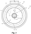
- the flame tube 122 and flame outlet 114 can be centered on and aligned with the central axis A, or as indicated in broken lines in Fig. 3 , they can be oriented tangential (offset as shown in Fig.
- the tangential orientation can help the flame from the torch 112 it to go more with the main air flow path in the main flow passage 108 rather than interrupt it.
- a torch fuel injector 124 is mounted to the fitting portion of the torch wall 118 to issue fuel into the combustion chamber 120.
- At least one ignitor 126 (not shown in Fig. 1 , but see Fig. 6 ) is mounted to fixture portion of the torch wall 118, passing through the torch wall 118 into the combustion chamber 120, positioned to ignite fuel issued from the torch fuel injector 124.
- the fuel nozzle 102 includes an upstream air swirler 128 of the main flow passage 108.
- the upstream air swirler 128 defines a plurality of circumferentially distributed passages 130, labeled in Fig. 3 , configured to impart swirl on a flow of air flowing therethrough.
- the plurality of passages 130 of the upstream air swirler are upstream of the flame outlet 114 with respect to the downstream direction D along the injection axis A.
- the fuel nozzle 102 includes a heat shield 132 outboard of the nozzle body 106 with an insulation gap 134 defined between the heat shield 132 and the nozzle body 106.
- the injection fuel line 110 passes through the heat shield 132 and nozzle body 106 at an upstream end of the fuel nozzle 102.
- the torch ignitor 112 including the flame outlet 114 passes through the heat shield 132 and nozzle body 106.
- a downstream air swirler 136 is defined by a circumferential array of radial passages 138 through the heat shield 132 and nozzle body 106 at a position downstream of the flame outlet 114 with respect to the downstream direction D along the injection axis A.
- the fuel nozzle 102 is allowed to grow (under thermal expansion/contraction) at different rates than heat shield 132, which is not fixed at both ends to prevent breaking due to differential thermal expansion).
- the dome or backside surfaces can be back side cooled, e.g. by flow through the gap 134, similarly to the cooling in the torch wall 118 to prevent heat from oxidizing the material.
- the fuel nozzle 102 includes a pressure atomizer 140 in the outlet end of the fuel line 110 in fluid communication with the fuel outlet 104 at an upstream end of the nozzle body 102.
- the fuel nozzle 102 can instead include an air blast atomizer 140 in fluid communication with the fuel outlet 104 in the upstream end of the nozzle body 102.
- the nozzle body 102 as shown in Fig. 2 is conical and opens in the downstream direction D along the injection axis A.
- any suitable nozzle body shape can be used, such as the cylindrical nozzle body 106 in Fig. 5 .
- a system 10 includes an engine case 12, e.g. of a gas turbine engine, with a combustor 14 included within the engine case 12.
- a plurality of fuel injectors 100 as described above connect from outside the engine case 12 to the upstream combustor dome wall 16 of the combustor 14 to issue fuel and air into the combustor 14 for combustion.
- Each of the fuel injectors 100 has its respective fuel nozzle 102 operatively connected (or associated even if it is not a hard connection) to the combustor 14 to issue a spray of fuel from the fuel outlet 104 (labeled in Fig. 2 ) in a downstream direction along the injection axis A (labeled in Fig. 2 ).
- the fuel injectors 100 are shown oriented axially with the injection axes A aligned with the main axis M (which is schematically indicated in Fig. 6 ) of the combustor 14 and engine case 12, it is also contemplated that the fuel injectors 100 can be oriented tangential relative to the main combustor M axis of the combustor 14, as shown schematically in the plan view of in Fig. 7 . This can allow for inducing swirl around the annular volume of the combustor 14. It is also contemplated as shown schematically in Fig. 8 (which is viewed from the same cross-sectional view as in Fig. 6 ), that the injection axes A of the fuel injectors 100 can be oriented radially inward or outward relative to a main combustor axis M of the combustor 14.
- Systems and methods as disclosed herein can allow extensive turndown (one torch device can remain stable while all others are turned off, for example. They can allow extensive redundancy, e.g. even if one or more torch devices fail through some failure modes, others can be adjusted to compensate until replacement can occur. Light-around problems can be reduced or eliminated. Systems and methods as disclosed herein can greatly improve altitude relight as multiple systems can be simultaneously ignited. There can be a reduction in the probability of altitude flameout. Individual injector/torch control can be used to break acoustic issues. Further devices can be employed in the main combustor to allow for adequate temperature uniformity and combustion efficiency such as air swirlers surrounding the torches, dilution jets, and combustion liner cooling features.
- Torches can be aimed to maximize performance.
- the elbow between the torch ignitor 112 and the fuel nozzle 102 can be given a partially tangential direction to improve main combustor mixing, as indicated in Fig. 3 , and can even have a tilt to the left or right as oriented as in Fig. 3 to suit given applications.
- Torches can be oriented for convenient locations and also to improve/maximize performance.
- Health monitoring can be setup for each fuel injector to provide feedback to monitor and improve overall health.
- thermocouples can be used as sensors for detecting flames and temperatures of each torch device. This can be coupled with individual control valves to increase/decrease the fuel flow to an individual device if its performance needs adjusted.
- Power through the ignitors 126 e.g. glow plugs, can be turned on if the device is not lit.
Landscapes
- Engineering & Computer Science (AREA)
- Chemical & Material Sciences (AREA)
- Combustion & Propulsion (AREA)
- Mechanical Engineering (AREA)
- General Engineering & Computer Science (AREA)
- Pressure-Spray And Ultrasonic-Wave- Spray Burners (AREA)
- Fuel-Injection Apparatus (AREA)
Abstract
Description
- The present disclosure relates to fuel injection and ignition, and more particularly to fuel injection and ignition in gas turbine engines.
- A small, independent torch igniter system offers many advantages for gas turbine engines. It offers an independent heat source from the main combustor which is used to ignite, stabilize, and relight the main combustor. The isolated nature of this system allows it to be stable regardless of the conditions within the main combustor. A torch ignitor can provide rapid relight capabilities.
- The conventional techniques have been considered satisfactory for their intended purpose. However, there is an ever present need for improved systems and methods for improved torch ignitor systems and methods. This disclosure provides a solution for this need.
- A fuel injector includes a fuel nozzle configured to issue a spray of fuel from a fuel outlet in a downstream direction along an injection axis. The fuel nozzle includes a nozzle body that defines a main flow passage therethrough. An injection fuel line is in fluid communication with the fuel nozzle to supply fuel to the fuel nozzle. A torch ignitor with a flame outlet opens into the main flow passage of the fuel nozzle for issuing flame into the main flow passage. The flame outlet meets the main flow passage at a position that is downstream of the fuel outlet with respect to the downstream direction along the injection axis.
- The main flow passage can define a main outlet for flame from the torch ignitor. The main outlet for flame can be radially bigger than the fuel outlet with respect to the injection axis. The torch ignitor can include a torch wall defining a combustion chamber therein. The combustion chamber can be connected to outlet flame through the flame outlet passing out of the torch wall and into the main flow passage of the fuel nozzle. A torch fuel injector can be mounted to the torch wall to issue fuel into the combustion chamber. At least one ignitor can be mounted to the torch wall, positioned to ignite fuel issued from the torch fuel injector. The combustion chamber can be connected to the flame outlet by flame tube. The flame tube and flame outlet can be oriented tangential relative to the injection axis to swirl flame from the combustion chamber around the main flow passage of the fuel nozzle.
- The fuel nozzle can include an upstream air swirler of the main flow passage, the upstream air swirler defining a plurality of passages configured to impart swirl on a flow of air flowing therethrough. The plurality of passages of the upstream air swirler can be upstream of the flame outlet with respect to the downstream direction along the injection axis. The fuel nozzle can include a heat shield outboard of the nozzle body with an insulation gap defined between the heat shield and the nozzle body. The injection fuel line can pass through the heat shield and nozzle body at an upstream end of the fuel nozzle. The torch ignitor can pass through the heat shield and nozzle body. A downstream air swirler can be defined by a circumferential array of radial passages through the heat shield and nozzle body at a position downstream of the flame outlet with respect to the downstream direction along the injection axis.
- The fuel nozzle can include a pressure atomizer in fluid communication with the fuel outlet at an upstream end of the nozzle body. The fuel nozzle can include an air blast atomizer in fluid communication with the fuel outlet in an upstream end of the nozzle body. The injection fuel line can be thermally isolated from the torch ignitor. The nozzle body can be conical and can open in the downstream direction along the injection axis. The nozzle body can be cylindrical. The injection fuel line and torch ignitor can define a feed arm that extends perpendicular relative to the injection axis of the fuel nozzle.
- A system includes an engine case. A combustor is included within the engine case. A plurality of fuel injectors connect from outside the engine case to the combustor to issue fuel and air into the combustor for combustion. Each of the fuel injectors in the plurality of fuel injectors is as described above, with the fuel nozzle connected to the combustor to issue a spray of fuel from a fuel outlet in a downstream direction along an injection axis.
- The fuel injectors of the plurality of fuel injectors can be oriented tangential relative to a main combustor axis of the combustor. The fuel injectors of the plurality of fuel injectors can be oriented radially inward relative to a main combustor axis of the combustor.
- These and other features of the systems and methods of the subject disclosure will become more readily apparent to those skilled in the art from the following detailed description of the preferred embodiments taken in conjunction with the drawings.
- So that those skilled in the art to which the subject disclosure appertains will readily understand how to make and use the devices and methods of the subject disclosure without undue experimentation, preferred embodiments thereof will be described in detail herein below with reference to certain figures, wherein:
-
Figs. 1-2 are schematic cross-sectional side elevation views of an injector, and a portion of the fuel injector, respectively, in accordance with the present disclosure, showing the torch ignitor, ignition fuel line, and fuel nozzle; -
Fig. 3 is a schematic downstream elevation view the fuel injector ofFig. 2 , showing possible locations for the flame outlet; -
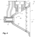
Fig. 4 is a schematic cross-sectional side elevation view of a portion of the fuel injector ofFig. 2 , showing an air blast injector at the upstream end of the nozzle body; -
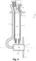
Fig. 5 is a schematic cross-sectional side elevation view of the fuel injector ofFig. 1 , showing a cylindrical nozzle body; -
Fig. 6 is a cross-sectional perspective view of a system incorporating fuel injectors ofFig. 1 ; and -
Figs. 7-8 are schematic plan and side elevation views, respectively, of the system ofFig. 6 , showing possible orientations of the fuel injectors. - Reference will now be made to the drawings wherein like reference numerals identify similar structural features or aspects of the subject disclosure. For purposes of explanation and illustration, and not limitation, a partial view of an embodiment of a fuel injector in accordance with the disclosure is shown in
Fig. 1 and is designated generally byreference character 100. Other embodiments of systems in accordance with the disclosure, or aspects thereof, are provided inFigs. 2-8 , as will be described. The systems and methods described herein can be used to provide fuel injectors with torch ignitors. - The
fuel injector 100 includes afuel nozzle 102 configured to issue a spray of fuel from afuel outlet 104 in a downstream direction D along an injection axis A. Thefuel nozzle 102 includes anozzle body 106 that defines amain flow passage 108 therethrough. Aninjection fuel line 110 is in fluid communication with thefuel nozzle 102 to supply fuel to thefuel nozzle 102. Atorch ignitor 112 with aflame outlet 114 opens into themain flow passage 108 of thefuel nozzle 102 for issuing flame into themain flow passage 108. Theflame outlet 114 meets themain flow passage 108 at a position that is downstream of thefuel outlet 104 with respect to the downstream direction D along the injection axis A. - With reference now to
Fig. 2 , themain flow passage 108 defines amain outlet 116 for flame from the torch ignitor. Themain outlet 116 for flame is radially bigger than thefuel outlet 104 with respect to the injection axis A. Thetorch ignitor 112 includes atorch wall 118 defining acombustion chamber 120 therein. Theinjection fuel line 110 is thermally isolated from thetorch ignitor 112, e.g. by being spaced apart therefrom and by theheat shield 111 of thefuel tube 110. Theheat shield 111 aroundinjection fuel line 110 provides air gap which insulates thefuel line 110 to keep the fuel from getting too hot. Theinjection fuel line 110 andtorch ignitor 112 define a feed arm that extends perpendicular relative to the injection axis A of thefuel nozzle 102. Thecombustion chamber 120 is connected to outlet flame through theflame outlet 114 passing out of thetorch wall 118 and into themain flow passage 108 of thefuel nozzle 102. Thecombustion chamber 120 is connected to theflame outlet 114 by aflame tube 122. As shown inFig. 3 , theflame tube 122 andflame outlet 114 can be centered on and aligned with the central axis A, or as indicated in broken lines inFig. 3 , they can be oriented tangential (offset as shown inFig. 3 ) relative to the injection axis A to swirl flame from thecombustion chamber 120 around themain flow passage 108 of thefuel nozzle 102. The tangential orientation can help the flame from thetorch 112 it to go more with the main air flow path in themain flow passage 108 rather than interrupt it. - With reference again to
Fig. 1 , atorch fuel injector 124 is mounted to the fitting portion of thetorch wall 118 to issue fuel into thecombustion chamber 120. At least one ignitor 126 (not shown inFig. 1 , but seeFig. 6 ) is mounted to fixture portion of thetorch wall 118, passing through thetorch wall 118 into thecombustion chamber 120, positioned to ignite fuel issued from thetorch fuel injector 124. - With reference again to
Fig. 2 , thefuel nozzle 102 includes anupstream air swirler 128 of themain flow passage 108. Theupstream air swirler 128 defines a plurality of circumferentially distributed passages 130, labeled inFig. 3 , configured to impart swirl on a flow of air flowing therethrough. The plurality of passages 130 of the upstream air swirler are upstream of theflame outlet 114 with respect to the downstream direction D along the injection axis A. Thefuel nozzle 102 includes aheat shield 132 outboard of thenozzle body 106 with aninsulation gap 134 defined between theheat shield 132 and thenozzle body 106. Theinjection fuel line 110 passes through theheat shield 132 andnozzle body 106 at an upstream end of thefuel nozzle 102. Thetorch ignitor 112 including theflame outlet 114 passes through theheat shield 132 andnozzle body 106. Adownstream air swirler 136 is defined by a circumferential array ofradial passages 138 through theheat shield 132 andnozzle body 106 at a position downstream of theflame outlet 114 with respect to the downstream direction D along the injection axis A. - The
fuel nozzle 102 is allowed to grow (under thermal expansion/contraction) at different rates thanheat shield 132, which is not fixed at both ends to prevent breaking due to differential thermal expansion). The dome or backside surfaces can be back side cooled, e.g. by flow through thegap 134, similarly to the cooling in thetorch wall 118 to prevent heat from oxidizing the material. - The
fuel nozzle 102 includes apressure atomizer 140 in the outlet end of thefuel line 110 in fluid communication with thefuel outlet 104 at an upstream end of thenozzle body 102. However, as shown inFig. 4 , it is also contemplated that thefuel nozzle 102 can instead include anair blast atomizer 140 in fluid communication with thefuel outlet 104 in the upstream end of thenozzle body 102. Thenozzle body 102 as shown inFig. 2 is conical and opens in the downstream direction D along the injection axis A. However, it is also contemplated that any suitable nozzle body shape can be used, such as thecylindrical nozzle body 106 inFig. 5 . - With reference now to
Fig. 6 , asystem 10 includes anengine case 12, e.g. of a gas turbine engine, with acombustor 14 included within theengine case 12. A plurality offuel injectors 100 as described above connect from outside theengine case 12 to the upstreamcombustor dome wall 16 of thecombustor 14 to issue fuel and air into thecombustor 14 for combustion. Each of thefuel injectors 100 has itsrespective fuel nozzle 102 operatively connected (or associated even if it is not a hard connection) to thecombustor 14 to issue a spray of fuel from the fuel outlet 104 (labeled inFig. 2 ) in a downstream direction along the injection axis A (labeled inFig. 2 ). While thefuel injectors 100 are shown oriented axially with the injection axes A aligned with the main axis M (which is schematically indicated inFig. 6 ) of thecombustor 14 andengine case 12, it is also contemplated that thefuel injectors 100 can be oriented tangential relative to the main combustor M axis of thecombustor 14, as shown schematically in the plan view of inFig. 7 . This can allow for inducing swirl around the annular volume of thecombustor 14. It is also contemplated as shown schematically inFig. 8 (which is viewed from the same cross-sectional view as inFig. 6 ), that the injection axes A of thefuel injectors 100 can be oriented radially inward or outward relative to a main combustor axis M of thecombustor 14. - In a gas turbine engine, replacement of one or more traditional fuel injectors with a continuous ignition device as disclosed herein allows complete control of each individual injection. This permits a large degree of fuel staging while still maintaining stability since each injection/torch system is independently controlled and isolated from disruptions of neighboring systems.
- Potential benefits include the following. Systems and methods as disclosed herein can allow extensive turndown (one torch device can remain stable while all others are turned off, for example. They can allow extensive redundancy, e.g. even if one or more torch devices fail through some failure modes, others can be adjusted to compensate until replacement can occur. Light-around problems can be reduced or eliminated. Systems and methods as disclosed herein can greatly improve altitude relight as multiple systems can be simultaneously ignited. There can be a reduction in the probability of altitude flameout. Individual injector/torch control can be used to break acoustic issues. Further devices can be employed in the main combustor to allow for adequate temperature uniformity and combustion efficiency such as air swirlers surrounding the torches, dilution jets, and combustion liner cooling features. Torches can be aimed to maximize performance. For example, the elbow between the
torch ignitor 112 and thefuel nozzle 102 can be given a partially tangential direction to improve main combustor mixing, as indicated inFig. 3 , and can even have a tilt to the left or right as oriented as inFig. 3 to suit given applications. Torches can be oriented for convenient locations and also to improve/maximize performance. Health monitoring can be setup for each fuel injector to provide feedback to monitor and improve overall health. For example, thermocouples can be used as sensors for detecting flames and temperatures of each torch device. This can be coupled with individual control valves to increase/decrease the fuel flow to an individual device if its performance needs adjusted. Power through theignitors 126, e.g. glow plugs, can be turned on if the device is not lit. - The methods and systems of the present disclosure, as described above and shown in the drawings, provide for fuel injectors with torch ignitors. While the apparatus and methods of the subject disclosure have been shown and described with reference to preferred embodiments, those skilled in the art will readily appreciate that changes and/or modifications may be made thereto without departing from the scope of the subject disclosure.
Claims (15)
- A fuel injector (100) comprising:a fuel nozzle (102) configured to issue a spray of fuel from a fuel outlet (104) in a downstream direction along an injection axis, the fuel nozzle including a nozzle body (106) that defines a main flow passage (108) therethrough;an injection fuel line (110) in fluid communication with the fuel nozzle (102) to supply fuel to the fuel nozzle; anda torch ignitor (112) with a flame outlet (114) opening into the main flow passage (108) of the fuel nozzle (102) for issuing flame into the main flow passage, wherein the flame outlet (114) meets the main flow passage (108) at a position that is downstream of the fuel outlet (104) with respect to the downstream direction along the injection axis.
- The fuel injector as recited in claim 1, wherein the main flow passage (108) defines a main outlet (116) for flame from the torch ignitor (112), and wherein the main outlet (116) for flame is radially bigger than the fuel outlet (104) with respect to the injection axis.
- The fuel injector as recited in claim 1 or 2, wherein the torch ignitor (112) includes:a torch wall (118) defining a combustion chamber (120) therein, wherein the combustion chamber (120) is connected to outlet flame through the flame outlet (114) passing out of the torch wall (118) and into the main flow passage (108) of the fuel nozzle;a torch fuel injector (124) mounted to the torch wall (118) to issue fuel into the combustion chamber (120); andat least one ignitor (126) mounted to the torch wall (118), positioned to ignite fuel issued from the torch fuel injector (124), and preferably wherein the combustion chamber (120) is connected to the flame outlet (114) by flame tube (122), and more preferably wherein the flame tube (122) and flame outlet (114) are oriented tangential relative to the injection axis to swirl flame from the combustion chamber (120) around the main flow passage (108) of the fuel nozzle.
- The fuel injector as recited in any preceding claim, wherein the fuel nozzle (102) includes an upstream air swirler (128) of the main flow passage (108), the upstream air swirler (128) defining a plurality of passages (130) configured to impart swirl on a flow of air flowing therethrough.
- The fuel injector as recited in claim 4, wherein the plurality of passages (130) of the upstream air swirler (128) are upstream of the flame outlet (114) with respect to the downstream direction along the injection axis.
- The fuel injector as recited in claim 4 or 5, wherein the fuel nozzle (102) includes a heat shield (132) outboard of the nozzle body (106), with an insulation gap (134) defined between the heat shield (132) and the nozzle body (106).
- The fuel injector as recited in claim 6, wherein the injection fuel line (110) passes through the heat shield (132) and nozzle body (106) at an upstream end of the fuel nozzle (102); and/orwherein the torch ignitor (112) passes through the heat shield (132) and nozzle body (106); and/orwherein a downstream air swirler (136) is defined by a circumferential array of radial passages (138) through the heat shield (132) and nozzle body (106) at a position downstream of the flame outlet (114) with respect to the downstream direction along the injection axis.
- The fuel injector as recited in any preceding claim, wherein the fuel nozzle (102) includes a pressure atomizer (140) in fluid communication with the fuel outlet (104) at an upstream end of the nozzle body (106).
- The fuel injector as recited in any of claims 1-7, wherein the fuel nozzle (102) incudes an air blast atomizer (140) in fluid communication with the fuel outlet (104) in an upstream end of the nozzle body (106).
- The fuel injector as recited in any preceding claim, wherein the injection fuel line (110) is thermally isolated from the torch ignitor.
- The fuel injector as recited in any preceding claim, wherein the nozzle body (106) is conical and opens in the downstream direction along the injection axis.
- The fuel injector as recited in any preceding claim, wherein the nozzle body (106) is cylindrical.
- The fuel injector as recited in any preceding claim, wherein the injection fuel line (110) and torch ignitor (112) define a feed arm that extends perpendicular relative to the injection axis of the fuel nozzle (102).
- A system comprising:an engine case (12);a combustor (14) within the engine case (12);a plurality of fuel injectors (100) connecting from outside the engine case (12) to the combustor to issue fuel and air into the combustor for combustion, wherein each of the fuel injectors in the plurality of fuel injectors includes a fuel injector of any preceding claim.
- The system as recited in claim 14, wherein the fuel injectors (100) of the plurality of fuel injectors are oriented tangential relative to a main combustor axis of the combustor (14); or
wherein the fuel injectors (100) of the plurality of fuel injectors are oriented radially inward relative to a main combustor axis of the combustor (14).
Applications Claiming Priority (1)
| Application Number | Priority Date | Filing Date | Title |
|---|---|---|---|
| US17/499,527 US11773784B2 (en) | 2021-10-12 | 2021-10-12 | Fuel injectors with torch ignitors |
Publications (2)
| Publication Number | Publication Date |
|---|---|
| EP4166848A1 true EP4166848A1 (en) | 2023-04-19 |
| EP4166848B1 EP4166848B1 (en) | 2024-12-18 |
Family
ID=83690433
Family Applications (1)
| Application Number | Title | Priority Date | Filing Date |
|---|---|---|---|
| EP22200776.7A Active EP4166848B1 (en) | 2021-10-12 | 2022-10-11 | Fuel injectors with torch ignitors |
Country Status (2)
| Country | Link |
|---|---|
| US (1) | US11773784B2 (en) |
| EP (1) | EP4166848B1 (en) |
Families Citing this family (4)
| Publication number | Priority date | Publication date | Assignee | Title |
|---|---|---|---|---|
| CN116878024B (en) * | 2023-07-28 | 2024-09-10 | 广东大唐国际雷州发电有限责任公司 | High reliability ignition device for π-type boilers of combustion generator sets |
| US12228086B1 (en) * | 2023-11-20 | 2025-02-18 | Solar Turbines Incorporated | Torch active control system |
| US12338774B1 (en) * | 2024-04-11 | 2025-06-24 | General Electric Company | Fuel injector manifold having a variable fuel flow system for a turbine engine |
| US12680505B1 (en) * | 2025-08-05 | 2026-07-14 | Rtx Corporation | Carbide torch igniter |
Citations (7)
| Publication number | Priority date | Publication date | Assignee | Title |
|---|---|---|---|---|
| GB1381719A (en) * | 1971-12-22 | 1975-01-22 | Tsnii T Mash I Khim Fiz Akadem | Production of a protective atmosphere in a metalheating furnace |
| US20100293953A1 (en) * | 2007-11-02 | 2010-11-25 | Siemens Aktiengesellschaft | Combustor for a gas-turbine engine |
| US20110041508A1 (en) * | 2008-04-01 | 2011-02-24 | Andreas Karlsson | Burner |
| US20110287373A1 (en) * | 2009-02-11 | 2011-11-24 | Edwards Limited | Pilot |
| US20120047903A1 (en) * | 2008-05-06 | 2012-03-01 | Delavan Inc. | Staged pilots in pure airblast injectors for gas turbine engines |
| US20170350590A1 (en) * | 2016-06-01 | 2017-12-07 | Board Of Regents, The University Of Texas System. | Swirl torch igniter |
| US20190017441A1 (en) * | 2017-07-17 | 2019-01-17 | General Electric Company | Gas turbine engine combustor |
Family Cites Families (28)
| Publication number | Priority date | Publication date | Assignee | Title |
|---|---|---|---|---|
| US2814339A (en) * | 1957-11-26 | Tunnel-type gas burner and double igni- | ||
| US2852642A (en) * | 1957-01-07 | 1958-09-16 | Ford Motor Co | Thermal responsive device |
| US3009321A (en) * | 1958-05-21 | 1961-11-21 | Rodney A Jones | Ceramic-lined pilots for turbo-jet combustors |
| US3361183A (en) * | 1965-07-28 | 1968-01-02 | Comb Efficiency Corp | Liquid fuel burner |
| US4012904A (en) * | 1975-07-17 | 1977-03-22 | Chrysler Corporation | Gas turbine burner |
| IT1063699B (en) | 1975-09-16 | 1985-02-11 | Westinghouse Electric Corp | STARTING METHOD OF A HIGH-POWER GAS TURBINE WITH A CATALYTIC COMBUSTOR |
| US4412414A (en) * | 1980-09-22 | 1983-11-01 | General Motors Corporation | Heavy fuel combustor |
| US4787208A (en) * | 1982-03-08 | 1988-11-29 | Westinghouse Electric Corp. | Low-nox, rich-lean combustor |
| US4860533A (en) | 1987-09-17 | 1989-08-29 | Prutech Ii | Torch igniter for a combustor having U.V. flame detection |
| US4854857A (en) * | 1988-11-23 | 1989-08-08 | Gas Research Institute | Torch ignitor |
| GB9122965D0 (en) * | 1991-10-29 | 1991-12-18 | Rolls Royce Plc | Turbine engine control system |
| US6182436B1 (en) * | 1998-07-09 | 2001-02-06 | Pratt & Whitney Canada Corp. | Porus material torch igniter |
| DE10211141A1 (en) | 2002-03-14 | 2003-09-25 | Alstom Switzerland Ltd | Method for igniting the combustion chamber of a gas turbine system and ignition device for carrying out the method |
| US6748735B2 (en) * | 2002-08-13 | 2004-06-15 | The Boeing Company | Torch igniter |
| US8044319B2 (en) | 2005-02-07 | 2011-10-25 | Pratt & Whitney Canada Corp. | Variable arc gap plasma igniter |
| US7571598B2 (en) | 2005-05-19 | 2009-08-11 | Virginia Tech Intellectual Properties, Inc. | Plasma torch for ignition, flameholding and enhancement of combustion in high speed flows |
| US9366435B2 (en) * | 2010-11-29 | 2016-06-14 | Mitsubishi Hitachi Power Systems, Ltd. | Ignition torch and pressurized gasification furnace including the same |
| US8925325B2 (en) * | 2011-03-18 | 2015-01-06 | Delavan Inc. | Recirculating product injection nozzle |
| JP5575221B2 (en) * | 2012-12-26 | 2014-08-20 | 三菱重工業株式会社 | Combustion burner and pressurized gasifier |
| US9567912B2 (en) * | 2013-06-13 | 2017-02-14 | Delavan Inc | Continuous ignition systems |
| US10584639B2 (en) | 2014-08-18 | 2020-03-10 | Woodward, Inc. | Torch igniter |
| AT516251B1 (en) | 2015-01-07 | 2016-04-15 | Hoerbiger Kompressortech Hold | Fuel gas supply and ignition device for a gas engine |
| US10393382B2 (en) * | 2016-11-04 | 2019-08-27 | General Electric Company | Multi-point injection mini mixing fuel nozzle assembly |
| US10704469B2 (en) | 2017-07-07 | 2020-07-07 | Woodward, Inc. | Auxiliary Torch Ingnition |
| US10711699B2 (en) | 2017-07-07 | 2020-07-14 | Woodward, Inc. | Auxiliary torch ignition |
| US10815893B2 (en) | 2018-01-04 | 2020-10-27 | Woodward, Inc. | Combustor assembly with primary and auxiliary injector fuel control |
| US20210215100A1 (en) | 2020-01-14 | 2021-07-15 | Rolls-Royce North American Technologies Inc. | Blow down impingement start system |
| JP7635081B2 (en) * | 2021-06-14 | 2025-02-25 | 東芝エネルギーシステムズ株式会社 | Burner with torch ignition mechanism and method for operating same |
-
2021
- 2021-10-12 US US17/499,527 patent/US11773784B2/en active Active
-
2022
- 2022-10-11 EP EP22200776.7A patent/EP4166848B1/en active Active
Patent Citations (7)
| Publication number | Priority date | Publication date | Assignee | Title |
|---|---|---|---|---|
| GB1381719A (en) * | 1971-12-22 | 1975-01-22 | Tsnii T Mash I Khim Fiz Akadem | Production of a protective atmosphere in a metalheating furnace |
| US20100293953A1 (en) * | 2007-11-02 | 2010-11-25 | Siemens Aktiengesellschaft | Combustor for a gas-turbine engine |
| US20110041508A1 (en) * | 2008-04-01 | 2011-02-24 | Andreas Karlsson | Burner |
| US20120047903A1 (en) * | 2008-05-06 | 2012-03-01 | Delavan Inc. | Staged pilots in pure airblast injectors for gas turbine engines |
| US20110287373A1 (en) * | 2009-02-11 | 2011-11-24 | Edwards Limited | Pilot |
| US20170350590A1 (en) * | 2016-06-01 | 2017-12-07 | Board Of Regents, The University Of Texas System. | Swirl torch igniter |
| US20190017441A1 (en) * | 2017-07-17 | 2019-01-17 | General Electric Company | Gas turbine engine combustor |
Also Published As
| Publication number | Publication date |
|---|---|
| US20230110714A1 (en) | 2023-04-13 |
| EP4166848B1 (en) | 2024-12-18 |
| US11773784B2 (en) | 2023-10-03 |
Similar Documents
| Publication | Publication Date | Title |
|---|---|---|
| EP4166848B1 (en) | Fuel injectors with torch ignitors | |
| EP4166847B1 (en) | Fuel injectors with torch ignitors | |
| US11428413B2 (en) | Fuel injection module for segmented annular combustion system | |
| US10584880B2 (en) | Mounting of integrated combustor nozzles in a segmented annular combustion system | |
| US10605459B2 (en) | Integrated combustor nozzle for a segmented annular combustion system | |
| US5685139A (en) | Diffusion-premix nozzle for a gas turbine combustor and related method | |
| US10520194B2 (en) | Radially stacked fuel injection module for a segmented annular combustion system | |
| US10563869B2 (en) | Operation and turndown of a segmented annular combustion system | |
| US8534040B2 (en) | Apparatus and method for igniting a combustor | |
| EP4019838B1 (en) | Torch ignitor sytem for a combustor of a gas turbine engine and method of operating the same | |
| US10641491B2 (en) | Cooling of integrated combustor nozzle of segmented annular combustion system | |
| WO2017165876A2 (en) | Segmented annular combustion system with axial fuel staging | |
| CN113864065B (en) | Methods of igniting liquid fuel in a turbine | |
| US20160305668A1 (en) | Fuel nozzle assembly including a pilot nozzle | |
| EP4141325B1 (en) | Torch ignitor system with cooled ignitor | |
| EP4019845B1 (en) | Torch ignitor system for a combustor of a gas turbine engine | |
| US3422620A (en) | Combustion apparatus | |
| US10634358B2 (en) | System and method for igniting liquid fuel in a gas turbine combustor | |
| EP4015908B1 (en) | Gas turbine engine combustor with axially oriented internally mounted continuous ignition device with reverse flow axial orientation |
Legal Events
| Date | Code | Title | Description |
|---|---|---|---|
| PUAI | Public reference made under article 153(3) epc to a published international application that has entered the european phase |
Free format text: ORIGINAL CODE: 0009012 |
|
| STAA | Information on the status of an ep patent application or granted ep patent |
Free format text: STATUS: THE APPLICATION HAS BEEN PUBLISHED |
|
| AK | Designated contracting states |
Kind code of ref document: A1 Designated state(s): AL AT BE BG CH CY CZ DE DK EE ES FI FR GB GR HR HU IE IS IT LI LT LU LV MC ME MK MT NL NO PL PT RO RS SE SI SK SM TR |
|
| STAA | Information on the status of an ep patent application or granted ep patent |
Free format text: STATUS: REQUEST FOR EXAMINATION WAS MADE |
|
| P01 | Opt-out of the competence of the unified patent court (upc) registered |
Effective date: 20230922 |
|
| 17P | Request for examination filed |
Effective date: 20231012 |
|
| RBV | Designated contracting states (corrected) |
Designated state(s): AL AT BE BG CH CY CZ DE DK EE ES FI FR GB GR HR HU IE IS IT LI LT LU LV MC ME MK MT NL NO PL PT RO RS SE SI SK SM TR |
|
| GRAP | Despatch of communication of intention to grant a patent |
Free format text: ORIGINAL CODE: EPIDOSNIGR1 |
|
| STAA | Information on the status of an ep patent application or granted ep patent |
Free format text: STATUS: GRANT OF PATENT IS INTENDED |
|
| INTG | Intention to grant announced |
Effective date: 20240726 |
|
| GRAS | Grant fee paid |
Free format text: ORIGINAL CODE: EPIDOSNIGR3 |
|
| GRAA | (expected) grant |
Free format text: ORIGINAL CODE: 0009210 |
|
| STAA | Information on the status of an ep patent application or granted ep patent |
Free format text: STATUS: THE PATENT HAS BEEN GRANTED |
|
| AK | Designated contracting states |
Kind code of ref document: B1 Designated state(s): AL AT BE BG CH CY CZ DE DK EE ES FI FR GB GR HR HU IE IS IT LI LT LU LV MC ME MK MT NL NO PL PT RO RS SE SI SK SM TR |
|
| REG | Reference to a national code |
Ref country code: CH Ref legal event code: EP |
|
| REG | Reference to a national code |
Ref country code: DE Ref legal event code: R096 Ref document number: 602022008803 Country of ref document: DE |
|
| REG | Reference to a national code |
Ref country code: IE Ref legal event code: FG4D |
|
| REG | Reference to a national code |
Ref country code: LT Ref legal event code: MG9D |
|
| PG25 | Lapsed in a contracting state [announced via postgrant information from national office to epo] |
Ref country code: HR Free format text: LAPSE BECAUSE OF FAILURE TO SUBMIT A TRANSLATION OF THE DESCRIPTION OR TO PAY THE FEE WITHIN THE PRESCRIBED TIME-LIMIT Effective date: 20241218 |
|
| PG25 | Lapsed in a contracting state [announced via postgrant information from national office to epo] |
Ref country code: FI Free format text: LAPSE BECAUSE OF FAILURE TO SUBMIT A TRANSLATION OF THE DESCRIPTION OR TO PAY THE FEE WITHIN THE PRESCRIBED TIME-LIMIT Effective date: 20241218 |
|
| PG25 | Lapsed in a contracting state [announced via postgrant information from national office to epo] |
Ref country code: BG Free format text: LAPSE BECAUSE OF FAILURE TO SUBMIT A TRANSLATION OF THE DESCRIPTION OR TO PAY THE FEE WITHIN THE PRESCRIBED TIME-LIMIT Effective date: 20241218 |
|
| PG25 | Lapsed in a contracting state [announced via postgrant information from national office to epo] |
Ref country code: NO Free format text: LAPSE BECAUSE OF FAILURE TO SUBMIT A TRANSLATION OF THE DESCRIPTION OR TO PAY THE FEE WITHIN THE PRESCRIBED TIME-LIMIT Effective date: 20250318 |
|
| REG | Reference to a national code |
Ref country code: NL Ref legal event code: MP Effective date: 20241218 |
|
| PG25 | Lapsed in a contracting state [announced via postgrant information from national office to epo] |
Ref country code: LV Free format text: LAPSE BECAUSE OF FAILURE TO SUBMIT A TRANSLATION OF THE DESCRIPTION OR TO PAY THE FEE WITHIN THE PRESCRIBED TIME-LIMIT Effective date: 20241218 Ref country code: GR Free format text: LAPSE BECAUSE OF FAILURE TO SUBMIT A TRANSLATION OF THE DESCRIPTION OR TO PAY THE FEE WITHIN THE PRESCRIBED TIME-LIMIT Effective date: 20250319 |
|
| PG25 | Lapsed in a contracting state [announced via postgrant information from national office to epo] |
Ref country code: RS Free format text: LAPSE BECAUSE OF FAILURE TO SUBMIT A TRANSLATION OF THE DESCRIPTION OR TO PAY THE FEE WITHIN THE PRESCRIBED TIME-LIMIT Effective date: 20250318 |
|
| PG25 | Lapsed in a contracting state [announced via postgrant information from national office to epo] |
Ref country code: NL Free format text: LAPSE BECAUSE OF FAILURE TO SUBMIT A TRANSLATION OF THE DESCRIPTION OR TO PAY THE FEE WITHIN THE PRESCRIBED TIME-LIMIT Effective date: 20241218 |
|
| REG | Reference to a national code |
Ref country code: AT Ref legal event code: MK05 Ref document number: 1752497 Country of ref document: AT Kind code of ref document: T Effective date: 20241218 |
|
| PG25 | Lapsed in a contracting state [announced via postgrant information from national office to epo] |
Ref country code: SM Free format text: LAPSE BECAUSE OF FAILURE TO SUBMIT A TRANSLATION OF THE DESCRIPTION OR TO PAY THE FEE WITHIN THE PRESCRIBED TIME-LIMIT Effective date: 20241218 |
|
| PG25 | Lapsed in a contracting state [announced via postgrant information from national office to epo] |
Ref country code: PL Free format text: LAPSE BECAUSE OF FAILURE TO SUBMIT A TRANSLATION OF THE DESCRIPTION OR TO PAY THE FEE WITHIN THE PRESCRIBED TIME-LIMIT Effective date: 20241218 |
|
| PG25 | Lapsed in a contracting state [announced via postgrant information from national office to epo] |
Ref country code: ES Free format text: LAPSE BECAUSE OF FAILURE TO SUBMIT A TRANSLATION OF THE DESCRIPTION OR TO PAY THE FEE WITHIN THE PRESCRIBED TIME-LIMIT Effective date: 20241218 |
|
| PG25 | Lapsed in a contracting state [announced via postgrant information from national office to epo] |
Ref country code: IS Free format text: LAPSE BECAUSE OF FAILURE TO SUBMIT A TRANSLATION OF THE DESCRIPTION OR TO PAY THE FEE WITHIN THE PRESCRIBED TIME-LIMIT Effective date: 20250418 |
|
| PG25 | Lapsed in a contracting state [announced via postgrant information from national office to epo] |
Ref country code: PT Free format text: LAPSE BECAUSE OF FAILURE TO SUBMIT A TRANSLATION OF THE DESCRIPTION OR TO PAY THE FEE WITHIN THE PRESCRIBED TIME-LIMIT Effective date: 20250421 |
|
| PG25 | Lapsed in a contracting state [announced via postgrant information from national office to epo] |
Ref country code: EE Free format text: LAPSE BECAUSE OF FAILURE TO SUBMIT A TRANSLATION OF THE DESCRIPTION OR TO PAY THE FEE WITHIN THE PRESCRIBED TIME-LIMIT Effective date: 20241218 |
|
| PG25 | Lapsed in a contracting state [announced via postgrant information from national office to epo] |
Ref country code: AT Free format text: LAPSE BECAUSE OF FAILURE TO SUBMIT A TRANSLATION OF THE DESCRIPTION OR TO PAY THE FEE WITHIN THE PRESCRIBED TIME-LIMIT Effective date: 20241218 Ref country code: RO Free format text: LAPSE BECAUSE OF FAILURE TO SUBMIT A TRANSLATION OF THE DESCRIPTION OR TO PAY THE FEE WITHIN THE PRESCRIBED TIME-LIMIT Effective date: 20241218 |
|
| PG25 | Lapsed in a contracting state [announced via postgrant information from national office to epo] |
Ref country code: SK Free format text: LAPSE BECAUSE OF FAILURE TO SUBMIT A TRANSLATION OF THE DESCRIPTION OR TO PAY THE FEE WITHIN THE PRESCRIBED TIME-LIMIT Effective date: 20241218 |
|
| PG25 | Lapsed in a contracting state [announced via postgrant information from national office to epo] |
Ref country code: CZ Free format text: LAPSE BECAUSE OF FAILURE TO SUBMIT A TRANSLATION OF THE DESCRIPTION OR TO PAY THE FEE WITHIN THE PRESCRIBED TIME-LIMIT Effective date: 20241218 |
|
| PG25 | Lapsed in a contracting state [announced via postgrant information from national office to epo] |
Ref country code: IT Free format text: LAPSE BECAUSE OF FAILURE TO SUBMIT A TRANSLATION OF THE DESCRIPTION OR TO PAY THE FEE WITHIN THE PRESCRIBED TIME-LIMIT Effective date: 20241218 |
|
| PG25 | Lapsed in a contracting state [announced via postgrant information from national office to epo] |
Ref country code: SE Free format text: LAPSE BECAUSE OF FAILURE TO SUBMIT A TRANSLATION OF THE DESCRIPTION OR TO PAY THE FEE WITHIN THE PRESCRIBED TIME-LIMIT Effective date: 20241218 |
|
| REG | Reference to a national code |
Ref country code: DE Ref legal event code: R097 Ref document number: 602022008803 Country of ref document: DE |
|
| PG25 | Lapsed in a contracting state [announced via postgrant information from national office to epo] |
Ref country code: DK Free format text: LAPSE BECAUSE OF FAILURE TO SUBMIT A TRANSLATION OF THE DESCRIPTION OR TO PAY THE FEE WITHIN THE PRESCRIBED TIME-LIMIT Effective date: 20241218 |
|
| PGFP | Annual fee paid to national office [announced via postgrant information from national office to epo] |
Ref country code: FR Payment date: 20250924 Year of fee payment: 4 |
|
| PLBE | No opposition filed within time limit |
Free format text: ORIGINAL CODE: 0009261 |
|
| STAA | Information on the status of an ep patent application or granted ep patent |
Free format text: STATUS: NO OPPOSITION FILED WITHIN TIME LIMIT |
|
| REG | Reference to a national code |
Ref country code: CH Ref legal event code: L10 Free format text: ST27 STATUS EVENT CODE: U-0-0-L10-L00 (AS PROVIDED BY THE NATIONAL OFFICE) Effective date: 20251029 |
|
| 26N | No opposition filed |
Effective date: 20250919 |
|
| PGFP | Annual fee paid to national office [announced via postgrant information from national office to epo] |
Ref country code: DE Payment date: 20250923 Year of fee payment: 4 |
|
| REG | Reference to a national code |
Ref country code: CH Ref legal event code: H13 Free format text: ST27 STATUS EVENT CODE: U-0-0-H10-H13 (AS PROVIDED BY THE NATIONAL OFFICE) Effective date: 20260527 |
|
| PG25 | Lapsed in a contracting state [announced via postgrant information from national office to epo] |
Ref country code: LU Free format text: LAPSE BECAUSE OF NON-PAYMENT OF DUE FEES Effective date: 20251011 |
|
| REG | Reference to a national code |
Ref country code: BE Ref legal event code: MM Effective date: 20251031 |
|
| PG25 | Lapsed in a contracting state [announced via postgrant information from national office to epo] |
Ref country code: LT Free format text: LAPSE BECAUSE OF FAILURE TO SUBMIT A TRANSLATION OF THE DESCRIPTION OR TO PAY THE FEE WITHIN THE PRESCRIBED TIME-LIMIT Effective date: 20241218 |
|
| PG25 | Lapsed in a contracting state [announced via postgrant information from national office to epo] |
Ref country code: MC Free format text: LAPSE BECAUSE OF FAILURE TO SUBMIT A TRANSLATION OF THE DESCRIPTION OR TO PAY THE FEE WITHIN THE PRESCRIBED TIME-LIMIT Effective date: 20241218 |
|
| PG25 | Lapsed in a contracting state [announced via postgrant information from national office to epo] |
Ref country code: BE Free format text: LAPSE BECAUSE OF NON-PAYMENT OF DUE FEES Effective date: 20251031 Ref country code: CH Free format text: LAPSE BECAUSE OF NON-PAYMENT OF DUE FEES Effective date: 20251031 |