EP4166837B1 - A protector assembly and associated method for protecting a threaded pipe - Google Patents
A protector assembly and associated method for protecting a threaded pipe Download PDFInfo
- Publication number
- EP4166837B1 EP4166837B1 EP21202494.7A EP21202494A EP4166837B1 EP 4166837 B1 EP4166837 B1 EP 4166837B1 EP 21202494 A EP21202494 A EP 21202494A EP 4166837 B1 EP4166837 B1 EP 4166837B1
- Authority
- EP
- European Patent Office
- Prior art keywords
- retainer
- rim
- fastener
- cover
- pin
- Prior art date
- Legal status (The legal status is an assumption and is not a legal conclusion. Google has not performed a legal analysis and makes no representation as to the accuracy of the status listed.)
- Active
Links
Images

Classifications
-
- F—MECHANICAL ENGINEERING; LIGHTING; HEATING; WEAPONS; BLASTING
- F16—ENGINEERING ELEMENTS AND UNITS; GENERAL MEASURES FOR PRODUCING AND MAINTAINING EFFECTIVE FUNCTIONING OF MACHINES OR INSTALLATIONS; THERMAL INSULATION IN GENERAL
- F16L—PIPES; JOINTS OR FITTINGS FOR PIPES; SUPPORTS FOR PIPES, CABLES OR PROTECTIVE TUBING; MEANS FOR THERMAL INSULATION IN GENERAL
- F16L57/00—Protection of pipes or objects of similar shape against external or internal damage or wear
- F16L57/005—Protection of pipes or objects of similar shape against external or internal damage or wear specially adapted for the ends of pipes
Definitions
- a protector assembly for covering a pin of a threaded pipe and a method for assembling such a protector assembly.
- Such assemblies and methods can find utility in the protection of threaded connectors used in the oil industry.
- those threaded connectors known as premium connections which comprise a pipe terminating at one end in a pin, which is a male threaded structure, for threaded engagement with a box, which is a female threaded structure configured to receive the pin.
- a box may be formed at the opposite end of the pipe, or the pipe may have a pin at both ends.
- a separate short coupling may be provided that has a box at both ends for connecting together two pipes.
- CN203023730U describes a pipeline rapid-plugging device which is provided with a press-against flange and a pipe cap flange.
- US2018135792A1 describes a universal thread protector is provided for protecting either of the pin and box ends of a pipe.
- EP3526439A1 describes a sealing device for sealing a free end of a generally tubular object.
- a protector assembly for covering a pin of a threaded pipe, comprising a cover, a retainer and at least one fastener for fastening the retainer to the cover, wherein: the cover includes a tubular portion defining a longitudinal axis from a closed end to an open end, the open end defining a rim for axial abutment with the retainer; the retainer has an abutment face for abutment with the rim; the rim comprises a bore extending therethrough; a fastener extends through the bore of the rim and engages the retainer, the fastener extending substantially in parallel with the longitudinal axis and exposed on the cover side of the bore of the rim for engagement by a tool or user to operate the fastener and wherein: the fastener threadably engages with the bore of the retainer; or the fastener engages the surface of the retainer.
- a method of assembling a protector assembly on a pin of a threaded pipe comprising the steps of: covering the pin of the threaded connector with a cover having a closed end and an open end defining a rim; engaging the pipe body with a retainer such that the retainer surrounds the pipe body; inserting a threaded fastener through the rim of the cover from the closed end side; and threadably engaging the retainer with the threaded fastener.
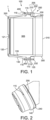
- Figures 1 to 3 show a first embodiment of a protector assembly 1 installed on a pipe 300 in accordance with the invention.
- the pipe 300 terminates in a pin 305 having a male thread for engagement with a female thread of a box.
- the protector assembly 1 does not include the pipe 300, but forms a pipe/protector assembly when installed thereon.
- the protector assembly 1 comprises a cover 100, a retainer 200 and at least one fastener 400.
- the cover 100 and the retainer 200 may be made from plastics, such as polyethylene (e.g., HDPE) or polypropylene.
- the cover 100 comprises a tubular portion 130 defining a longitudinal axis from a closed end 120 to an open end 125, the open end 125 defining a rim 110 for axial abutment with the retainer 200.
- the rim 110 may be a radial extension around the perimeter of the cover 100.
- the tubular portion 130 and closed end 120 are sized and shaped for covering the pin 305 of a pipe 300.
- the closed end 120 is therefore a circular disc at the end of the tubular portion 130, which is cylindrical, frustoconical, or a combination of cylindrical and frustoconical sections.
- the tubular portion 130 when intended for covering a pin 305 with a tapered thread, includes a tapered section, which tapers at the same angle as the thread of the pin 305.
- the end of the pin 305 may abut the inside of the cover 120.
- the cover 100 may have an inner surface that is approximately the same shape as at least a portion of the outer surface of the pin 305 that it is intended to cover.
- the cover 100 comprises an internal coupling thread 135 for engagement with a pin 305.
- the internal coupling thread 135 may be formed on the inner surface of the tubular portion 130.
- the rim 110 has an abutment face 150 for abutment with the retainer 200.
- the rim 110 comprises one or more bores 115 extending therethrough.
- the bores 115 of the rim 110 may or may not be threaded.
- the retainer 200 is arranged to extend radially closer to the longitudinal axis than the rim 110. In this way, when the retainer 200 is fastened to the cover 100 by the fastener 400, the retainer can engage a part of the pin 305, such as a shoulder 350, that the rim 110 would not engage.
- the retainer 200 has a circular opening 240 and an abutment face 250 perpendicular to the longitudinal axis (the longitudinal axis extends through the centre of the circular opening 240 and perpendicular to the plane of the circle) for abutment with the abutment face 150 of the rim 110.
- the retainer 200 is ring-shaped.
- the retainer 200 comprises one or more bores 230 extending into the abutment face 250.
- a tapered opening 235 may be provided in the abutment face 250 to guide the fastener 400 into the bore 230.
- the bores 230 of the retainer correspond with those of the cover 100.
- the retainer 200 comprises a threaded bore 230.
- the retainer 200 may be formed of a single material having the bores 230 formed therein, such that it is free of inserts.
- inserts such as nuts may be provided to define the (or a part of the) bores 230.
- Such inserts would preferably be rotationally held within a main body part of the retainer 200. This may be achieved, for example, by having a non-circular shaped cut out (such as a hexagon) complementary to an outer surface of the insert within the main body part of the retainer 200 within which the inserts are held.
- the retainer 200 includes a first end 210 and a second end 220.
- the first end 210 and the second end 220 meet at an overlap section 205.
- the ends 210, 220 overlap circumferentially. That is, the retainer 200 from first end 210 to second end 220 extends more than 360 degrees around the pipe 300.
- the bore 230 of the retainer 200 may extend through the overlap section 205 for enabling a single fastener 400 to both engage the cover 100 with the retainer 200, and engage the first end 210 with the second end 220.
- the bore 230 is threaded throughout both of the first and second ends 210, 220.
- the fastener 400 extends through the bore 230 through first end 210 without threadingly engaging the first end 210, and threadably engages the bore 230 through the second end 220 to fasten together the first and second ends 210, 220.
- the second end 220 is further from the cover 100 than the first end 210 (that is, the first end 210 is held between the cover 100 and the second end 220 on the fastener 400).
- the retainer 200 is a split ring as shown in Figure 4a . That is, the retainer 200 is a single, continuous piece of material between the first and second ends 210, 220.
- the retainer may be made of a resilient material such that it can be elastically deformed to separate the first and second ends 210, 220 so that the pipe body 300 can be inserted therebetween.
- the retainer 200 is a ring assembly comprising a first part 200a having the first end 210 and a second part 200b having the second end 220.
- the first and second parts 200a, 200b can collectively surround a pipe 300.
- the first and second parts 200a, 200b may be arc-shaped , or generally arc-shaped.
- the first and second ends 210, 220 meet to form overlap section 205.
- the other ends of the first and second parts 200a, 200b meet to form a further overlap section 206.
- the retainer 200 may include a hinge such that it can be opened and closed around the pipe 300. In such cases, the hinge is not necessarily fastened by a fastener extending through the cover 100.
- a retainer 200 formed as a ring assembly be limited to two parts. Multiple parts may be provided. As shown in Figure 4c , three (or more) parts 200a, 200b, 200c may be provided to collectively surround a pipe 300 providing an overlap section 205 between the first and second ends 210, 220 of two of the parts 200a, 200b, and further overlap sections 206 between other ends of the parts 200a, 200b, 200c.
- the three or more parts 200a, 200b, 200c may be arc-shaped , or generally arc-shaped.
- the other overlap sections 206 have the same configuration as the overlap section 205 of the first and second ends 210, 220.
- the first and second ends 210, 220 are shaped so as to define interfitting shoulders that abut in the circumferential direction (that is, the direction around the perimeter of the pipe 300) and overlap to form the overlap section 205.
- the first end 210 of the retainer 200 has a recess 212 shaped to receive the second end 220, while the second end 220 has a recess shaped to receive the first end 210.
- the recess of the first end 210 may form an internal shoulder having a surface 216 for circumferential abutment with the tip 226 of the second end 220, and a surface 218 for longitudinal abutment (i.e., perpendicular to the circumferential direction, in line with the longitudinal direction of the cover 100 when the protector assembly 1 is assembled) with a complementary surface 228 of the second end 220.
- the second end 220 is formed in a complementary way, with an internal shoulder having a circumferential abutment surface 224 for abutting the tip 214 of the first end 210 and a surface 228 for longitudinal abutment with the complementary surface 218 of the first end 210.
- first and second ends 210, 220 are shaped for abutment both circumferentially and longitudinally.
- ring-shaped and ring assembly are not intended to limit the shape of the item to a strict torus, but merely mean to denote an item that can extend around the perimeter of the pipe.
- the rim 110 may include a notch 140, for example in the abutment face 150 (as shown), and the retainer 200 may include a projection 240, located for engagement with the notch 140.
- the rim 110 may include a projection (for example in the same location as the notch is shown), and the retainer 200 may include a notch 240.
- the notch and projection may be located such that when they are engaged, the bores 115, 230 of the cover 100 and the retainer 200 are aligned.
- the cover 100 and the retainer 200 are rotationally aligned about the longitudinal axis, when the notch 140 and projection 240 are engaged.
- the fastener 400 fastens the cover 100 to the retainer 200.
- the fastener 400 is exposed on the cover side of the bore of the rim such that it may be engaged by a tool or user to operate the fastener.
- the tool could be a screwdriver that operates the fastener 400 by rotating it. Such rotation can operate the fastener 400 by threadably engaging the fastener 400 with the bore 230.
- the fastener 400 comprises a head portion 410 and a threaded portion 430, and optionally a stem portion 420.
- the stem portion 420 may be unthreaded.
- the head portion 410 of the fastener 400 may have a greater outer diameter than the diameter of bore 115.
- the head portion 410 is shaped for rotational engagement by a tool. That is, a tool (such as a screwdriver or Allen key) may be engaged with the head portion 410 so that rotation of the tool rotates the fastener 400 and thereby engages or disengages the fastener 400 from the retainer 200.
- a tool such as a screwdriver or Allen key
- the head portion 410 is at one end of the fastener 400 and the threaded portion 430 is at the opposite end of the fastener 400.
- the stem portion 420 when provided, links the head portion 410 to the threaded portion 430.
- the threaded portion 430 extends all the way to the head portion 410.
- the bore 115 of the cover 100 aligns with the bore 230 of the retainer 200.
- the fastener 400 extends through the bore 115 of the rim 110 for threadable engagement with the bore 230 of the retainer 200.
- the bore 230 through the retainer 200 is preferably formed in the material of the first and second ends without the provision of any form of insert made of different material.
- the fastener 400 threadably engages the bore 115 of the rim 110 as well as the bore 230 of the retainer 200. In such cases, no stem portion 420 is needed.
- the bore 115 of the rim 110 does not include threads and is sized for the threaded portion 430 of the fastener 400 to be slid therethrough without the threads engaging the cover 100.
- the threaded portion 430 extends beyond the abutment surface 150 of the rim 110. This protruding section of the fastener 400 can threadably engage the bore 230 of the ring assembly 200.
- a counter bore or counter sink 116 may be provided such that the head 410 of the fastener 400 is within the rim 110 when the protector assembly 1 is assembled.
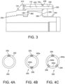
- the head 410 of the fastener 400 may be outside the rim 110. In either case, it is preferred that, when the protector assembly 1 is assembled, the head portion 410 is exposed on the closed end side of the rim 110 for engagement with a tool. As can be seen in Figure 3 , the head portion 410 is exposed such that it is accessible from the closed end side of the cover 100.
- the protector assembly 1 includes a plurality of fasteners, spaced around the periphery of the rim 110.
- the retainer 200 is formed as a ring assembly having a plurality of parts meeting at an overlap section 205 and one or more further overlap sections 206
- a fastener 400 for each overlap section 205, 206.
- additional fasteners 400 may be provided to extend through the cover 100 and threadably engage the retainer 200 at a location other than at an overlap 205, 206.
- additional fasteners 400 may be provided to extend through the cover 100 and threadably engage the retainer 200 at one or more spaced apart locations other than at an overlap 205, 206. Such additional fasteners 400 may extend into threaded bores 232 through single parts of the retainer 200.
- the protector assembly 1 forms a pipe protector assembly when installed on the pipe 300.
- the pipe protector assembly 1 comprises the cover 100, the retainer 200, the at least one fastener 400, and the pipe 300.
- the pipe 300 includes a pipe body 310, which extends to the pin 305.
- the pin 305 includes a terminal abutment surface 320 at the extreme end of the pipe 300 for abutment with the inside of the cover 120
- the pin 305 will have a tapered thread 335 for engagement with a female thread of a box and for engagement with a complementary thread 135 if this is formed on the internal surface of the cover 100.
- the tubular portion 130 includes a tapered section, which tapers at the same angle as the thread of the pin 305.
- the inner surface of the tubular portion 130 may simply be smooth and overly the crests of the pin thread 335, or (as shown in the Figures) an internal coupling thread 135 may be formed on the inner surface of the tubular portion 130 for engagement with the thread 335 of the pin 305.
- the pin 305 may have one or more shoulders 350, 360 along its length for axial abutment.
- a forward facing shoulder 360 forward facing meaning facing towards the terminal end of the pin 305 may be provided for abutting an internal shoulder of a box.
- the rear surface of the pin 305 may be formed with a rear facing shoulder 350 (rear facing meaning facing away from the terminal end of the pin 305).
- the rear facing shoulder may be without utility in connecting the pin 305 to a box, but can be used for abutment with the retainer 200.
- the cover 100 may comprise an internal shoulder 160 for abutment with the forward facing shoulder 360. This can provide good axial alignment of the cover 100 with the pin 305 when installed.
- the internal shoulder 160 may be formed on the internal surface of the rim 110, with the rim 110 extending longitudinally past the internal shoulder 160 (in a direction away from the cover 120) to the abutment face 150.
- the abutment face 250 of the retainer 200 may extend radially inwardly for abutment not only with the abutment face 150 of the rim 110, but also with the rear facing shoulder 250.
- the rim 110 preferably extends longitudinally (in a direction away from the cover 120) such that the abutment face 150 is aligned with the rear facing shoulder 350.
- the circular opening 240 of the retainer 200 has a radius that is less than the outer diameter of the rear facing shoulder 350.
- the protector assembly 1 may be installed so as to abut the forward facing shoulder 360 and the rear facing shoulder 350 and thereby prevent axial movement of the protector assembly 1 relative to the pipe 300.
- the abutments with the shoulders 350, 360 of the pin can be of sufficient pressure to form seals to hinder or prevent ingress of fluid (e.g. liquid) into the cover 100 for thereby protecting the pin 305 from corrosion.
- the cover 100 and the retainer 200 may define an annular channel therebetween, for example, by virtue of the internal shoulder 160 of the cover 100 and the radially innermost region of the abutment face 250 of the retainer 200. That annular channel of the protector assembly 1 can receive a radial extension of the pin 305 for relative axial alignment of the pin 305 and the protector assembly 1.
- the pin 305 may include a radially extending groove into which a radially extending part of the protector assembly 1 may be inserted.
- the retainer 200 may sit within the groove. Once the cover 100 is attached to such a retainer 200, the entire protector assembly 1 will be locked in an axial position.
- the annular channel and/or radially extending part of the protector assembly 1 may be located at an axial distance from tapered thread 335 and/or complementary thread 135. In particular, the annular channel and/or radially extending part of the protector assembly 1 may be located closer to the open end 125 of the cover than the tapered thread 335 and/or the complementary thread 135.
- An embodiment of the protector assembly 1 comprising the annular channel and/or radially extending part, wherein the to be protected pipe 300 comprises a complementary radial extension or complementary radially extending groove of the pin 305, works in particular well in combination with embodiments having one or more fasteners 400, wherein the head portion(s) 410 thereof is/are exposed.
- the protector assembly 1 may be installed on the pin 305 of a threaded pipe 300 by a method that includes: covering the pin 305 with the cover 100; engaging the pipe body 310 with the retainer 200; and fastening the cover 100 to the retainer 200 with the threaded fastener 400.
- the retainer 200 may be engaged with the pipe body 310 before or after the cover 100 covers the pin 305.
- Covering the pin 305 with the cover 100 may involve sliding the cover 100 axially over the pin 305 and/or threadably engaging the internal coupling thread 135 with the thread 335 of the pin 305.
- Covering the pin 305 with the cover 100 may comprise abutting the inner surface of the closed end 120 with the terminal abutment surface 320 and/or abutting the inner shoulder 160 with the forward facing shoulder 360.
- Engaging the pipe body 310 with the retainer 200 surrounds the pipe body 310 with the opening 240 of the retainer 200.
- engaging the pipe body 310 with the retainer 200 involves deforming the split ring and inserting the pipe body 310 between the first and second ends 210, 220.
- the split ring 200 is preferably formed of elastically deformable material so as to revert to its original shape once the pipe body 310 has been inserted.
- engaging the pipe body 310 with the retainer 200 involves fastening the first and second parts 200a, 200b together around the pipe body 310.
- the method may involve the step of fastening together the first and second ends 210, 220.
- the first and second ends 210, 220 are preferably abutted longitudinally (in the direction of the longitudinal axis of the tubular portion 130 of the cover 100) and circumferentially (in the direction around the perimeter of the pipe body 310).
- the retainer 200 and cover 100 may be rotationally aligned by insertion of a projection 240 of the retainer 200 into a notch 140 of the cover 100.
- the retainer 200 and cover 100 may be rotationally aligned by insertion of a projection of the cover 100 (not shown) into a notch of the retainer 200.
- Fastening the cover 100 to the retainer 200 with the threaded fastener 400 may comprise engaging the cover 100, the first end 210 and the second end 220 with the threaded fastener 400.
- the second end 220 may be threadably engaged with the threaded fastener 400.
- both the first and second ends 210, 220 are threadably engaged with the threaded fastener 400.
- the cover 100 is not threadably engaged with the threaded fastener 400.
- the fastener 400 is provided with a head portion 410 that abuts the cover 100 to fasten it to the retainer 200.
- the fastener may be screwed into the bore 230 of the retainer 200 until the head portion 410 is entirely within the counter bore or counter sink 116.
- the threaded fastener 400 is inserted in the longitudinal direction (in the direction of the longitudinal axis of the tubular portion 130 of the cover 100), and is inserted through the rim 110 of the cover 100 from the side of the closed end 120. In this way, when a plurality of pipes 300 are stacked, the operator can carry out the installation of the protector assembly 1 from the end of the stack without hindrance by the other pipes 300 of the stack.
- a plurality of fasteners 400 are used to secure the cover 100 to the retainer 200.
- the retainer 200 is either a split-ring or a ring assembly
- embodiments are contemplated in which one or more (preferably, at least three) independent retainer(s) 1200a, 1200b, 1200c, 1200d are provided.
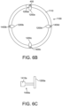
- Figures 6a to 6c show an example.
- FIG 6a there can be seen a cover 1100 with a rim 1110 having a bore through which a fastener 1400a extends.
- the fastener 1400a extends to a retainer 1200a.
- the fastener 1400a is attached to the retainer 1200a such that they rotate together.
- rotation of the retainer 1200a by rotating the fastener 1400a can rotate the retainer 1200a into a first position in which it extends radially inwardly and may engage an external shoulder of a pipe 1300, and can rotate the retainer 1200a into a second position in which it does not engage an external shoulder of a pipe 1300 (shown as 1200a' with dashed lines in Figure 6b ).
- the retainer 1200a may comprise a bore for receiving the fastener 1400a, or the fastener 1400a may engage the surface of the retainer 1200a.
- the fastener 1400a preferably has a head portion 1410a for rotational engagement by a tool. That is, a tool (such as a screwdriver or Allen key) may be engaged with the head portion 1410a so that rotation of the tool rotates the fastener 1400a and thereby rotates the associated retainer 1200a between the first and second positions.
- a tool such as a screwdriver or Allen key
- the fastener 1400 extends through the bore of the rim 1110 to engage the retainer 1200.
- the fastener 1400 extends substantially in parallel with the longitudinal axis of the cover 1100.
- the fastener 1400 is exposed on the cover side of the bore of the rim for engagement by a tool.
- the fastener 1400a is exposed such that it may be grasped by a worker and rotated by hand.
- the user mounting the cover assembly on a pipe can lock the cover in place using the retainer by manipulation of the fastener on the closed end side, without needing to access the open end side (opposite the closed end side) of the cover.
Landscapes
- Engineering & Computer Science (AREA)
- General Engineering & Computer Science (AREA)
- Mechanical Engineering (AREA)
- Protection Of Pipes Against Damage, Friction, And Corrosion (AREA)
Description
- The following describes a protector assembly for covering a pin of a threaded pipe and a method for assembling such a protector assembly. Such assemblies and methods can find utility in the protection of threaded connectors used in the oil industry. In particular, those threaded connectors known as premium connections, which comprise a pipe terminating at one end in a pin, which is a male threaded structure, for threaded engagement with a box, which is a female threaded structure configured to receive the pin. A box may be formed at the opposite end of the pipe, or the pipe may have a pin at both ends. When the pipe has a pin at both ends, a separate short coupling may be provided that has a box at both ends for connecting together two pipes.
- It is known to cover the pin during storage in order to protect it from impacts or corrosion. Typically, the protection devices used are difficult to install on the pin. There is therefore a need for a simple, easy to assemble protector assembly.
-
CN203023730U describes a pipeline rapid-plugging device which is provided with a press-against flange and a pipe cap flange.US2018135792A1 describes a universal thread protector is provided for protecting either of the pin and box ends of a pipe.EP3526439A1 describes a sealing device for sealing a free end of a generally tubular object. - Accordingly, the following describes a protector assembly for covering a pin of a threaded pipe, comprising a cover, a retainer and at least one fastener for fastening the retainer to the cover, wherein: the cover includes a tubular portion defining a longitudinal axis from a closed end to an open end, the open end defining a rim for axial abutment with the retainer; the retainer has an abutment face for abutment with the rim; the rim comprises a bore extending therethrough; a fastener extends through the bore of the rim and engages the retainer, the fastener extending substantially in parallel with the longitudinal axis and exposed on the cover side of the bore of the rim for engagement by a tool or user to operate the fastener and wherein: the fastener threadably engages with the bore of the retainer; or the fastener engages the surface of the retainer.
- There is also described a method of assembling a protector assembly on a pin of a threaded pipe, comprising the steps of: covering the pin of the threaded connector with a cover having a closed end and an open end defining a rim; engaging the pipe body with a retainer such that the retainer surrounds the pipe body; inserting a threaded fastener through the rim of the cover from the closed end side; and threadably engaging the retainer with the threaded fastener.
- When a large number of pipes are stacked for storage or transport, an operator can use the assemblies and methods described herein to cover the end of the pins in the middle of the stack. Using conventional pin covers, this would require reaching awkwardly past the end of the pin to use a tool that will extend perpendicular to the pipe. Of course, when the pipe is in a stack, the use of such a tool is hindered by the neighbouring pipes. The described assemblies and methods can enable an operator to easily cover a pin of a threaded pipe merely accessing the assembly from the cover side, without needing to reach around the cover or use a tool other than at the cover side of the assembly.
- For a better understanding of the invention, and to show how the same may be put into effect, reference will now be made, by way of example only, to the accompanying drawings in which:
-
Figure 1 shows a cross-section of a first embodiment of a protector assembly installed on a pipe in accordance with the invention; -
Figure 2 shows a perspective view of the protector assembly ofFigure 1 ; -
Figure 3 shows an enlarged region ofFigure 1 ; -
Figures 4a to 4c show alternative embodiments of retainers for use in a protector assembly in accordance with the invention; -
Figure 5 shows a close-up of an overlap section; and -
Figures 6a to 6c show an alternative protector assembly. -
Figures 1 to 3 show a first embodiment of a protector assembly 1 installed on apipe 300 in accordance with the invention. - As is conventional in the oil and gas industry, the
pipe 300 terminates in apin 305 having a male thread for engagement with a female thread of a box. The protector assembly 1 does not include thepipe 300, but forms a pipe/protector assembly when installed thereon. - The protector assembly 1 comprises a
cover 100, aretainer 200 and at least onefastener 400. - The
cover 100 and theretainer 200 may be made from plastics, such as polyethylene (e.g., HDPE) or polypropylene. - The
cover 100 comprises atubular portion 130 defining a longitudinal axis from a closedend 120 to anopen end 125, theopen end 125 defining arim 110 for axial abutment with theretainer 200. - The
rim 110 may be a radial extension around the perimeter of thecover 100. - The
tubular portion 130 and closedend 120 are sized and shaped for covering thepin 305 of apipe 300. In preferred embodiments, the closedend 120 is therefore a circular disc at the end of thetubular portion 130, which is cylindrical, frustoconical, or a combination of cylindrical and frustoconical sections. - Preferably, when intended for covering a
pin 305 with a tapered thread, thetubular portion 130 includes a tapered section, which tapers at the same angle as the thread of thepin 305. The end of thepin 305 may abut the inside of thecover 120. - For example, the
cover 100 may have an inner surface that is approximately the same shape as at least a portion of the outer surface of thepin 305 that it is intended to cover. - Optionally, the
cover 100 comprises aninternal coupling thread 135 for engagement with apin 305. Theinternal coupling thread 135 may be formed on the inner surface of thetubular portion 130. -
Surface features 121 may be provided on the outer surface of the closedend 120 for engaging a tool for rotating thecover 100. This can assist, in particular, for removing thecover 100 from thepin 305. - The
rim 110 has anabutment face 150 for abutment with theretainer 200. Therim 110 comprises one ormore bores 115 extending therethrough. Thebores 115 of therim 110 may or may not be threaded. - The
retainer 200 is arranged to extend radially closer to the longitudinal axis than therim 110. In this way, when theretainer 200 is fastened to thecover 100 by thefastener 400, the retainer can engage a part of thepin 305, such as ashoulder 350, that therim 110 would not engage. - The
retainer 200 has acircular opening 240 and anabutment face 250 perpendicular to the longitudinal axis (the longitudinal axis extends through the centre of thecircular opening 240 and perpendicular to the plane of the circle) for abutment with theabutment face 150 of therim 110. Preferably, theretainer 200 is ring-shaped. - The
retainer 200 comprises one ormore bores 230 extending into theabutment face 250. For assisting with the alignment of afastener 400 during insertion, atapered opening 235 may be provided in theabutment face 250 to guide thefastener 400 into thebore 230. Thebores 230 of the retainer correspond with those of thecover 100. - Preferably, the
retainer 200 comprises a threadedbore 230. - The
retainer 200 may be formed of a single material having thebores 230 formed therein, such that it is free of inserts. Alternative, inserts such as nuts may be provided to define the (or a part of the)bores 230. Such inserts would preferably be rotationally held within a main body part of theretainer 200. This may be achieved, for example, by having a non-circular shaped cut out (such as a hexagon) complementary to an outer surface of the insert within the main body part of theretainer 200 within which the inserts are held. - In preferred embodiments, the
retainer 200 includes afirst end 210 and asecond end 220. - When installed on a
pipe 300, thefirst end 210 and thesecond end 220 meet at anoverlap section 205. In theoverlap section 205, theends retainer 200 fromfirst end 210 tosecond end 220 extends more than 360 degrees around thepipe 300. - The
bore 230 of theretainer 200 may extend through theoverlap section 205 for enabling asingle fastener 400 to both engage thecover 100 with theretainer 200, and engage thefirst end 210 with thesecond end 220. - Preferably, the
bore 230 is threaded throughout both of the first andsecond ends fastener 400 extends through thebore 230 throughfirst end 210 without threadingly engaging thefirst end 210, and threadably engages thebore 230 through thesecond end 220 to fasten together the first andsecond ends second end 220 is further from thecover 100 than the first end 210 (that is, thefirst end 210 is held between thecover 100 and thesecond end 220 on the fastener 400). - In one preferred embodiment, the
retainer 200 is a split ring as shown inFigure 4a . That is, theretainer 200 is a single, continuous piece of material between the first andsecond ends pipe body 300 can be inserted therebetween. - In another preferred embodiment, the
retainer 200 is a ring assembly comprising afirst part 200a having thefirst end 210 and asecond part 200b having thesecond end 220. The first andsecond parts pipe 300. For example, the first andsecond parts - The first and second ends 210, 220 meet to form
overlap section 205. The other ends of the first andsecond parts further overlap section 206. Alternatively, theretainer 200 may include a hinge such that it can be opened and closed around thepipe 300. In such cases, the hinge is not necessarily fastened by a fastener extending through thecover 100. - As will be appreciated, it is not necessary that a
retainer 200 formed as a ring assembly be limited to two parts. Multiple parts may be provided. As shown inFigure 4c , three (or more)parts pipe 300 providing anoverlap section 205 between the first and second ends 210, 220 of two of theparts sections 206 between other ends of theparts more parts - Preferably, the
other overlap sections 206 have the same configuration as theoverlap section 205 of the first and second ends 210, 220. - As best shown in
Figure 2 , the first and second ends 210, 220 are shaped so as to define interfitting shoulders that abut in the circumferential direction (that is, the direction around the perimeter of the pipe 300) and overlap to form theoverlap section 205. - In the particular example shown in
Figure 5 , thefirst end 210 of theretainer 200 has arecess 212 shaped to receive thesecond end 220, while thesecond end 220 has a recess shaped to receive thefirst end 210. - The recess of the
first end 210 may form an internal shoulder having asurface 216 for circumferential abutment with thetip 226 of thesecond end 220, and a surface 218 for longitudinal abutment (i.e., perpendicular to the circumferential direction, in line with the longitudinal direction of thecover 100 when the protector assembly 1 is assembled) with acomplementary surface 228 of thesecond end 220. Thesecond end 220 is formed in a complementary way, with an internal shoulder having acircumferential abutment surface 224 for abutting thetip 214 of thefirst end 210 and asurface 228 for longitudinal abutment with the complementary surface 218 of thefirst end 210. - Other configurations are possible, however, it is preferable that the first and second ends 210, 220 are shaped for abutment both circumferentially and longitudinally.
- The terms ring-shaped and ring assembly are not intended to limit the shape of the item to a strict torus, but merely mean to denote an item that can extend around the perimeter of the pipe.
- The
rim 110 may include a notch 140, for example in the abutment face 150 (as shown), and theretainer 200 may include aprojection 240, located for engagement with the notch 140. In the alternative, therim 110 may include a projection (for example in the same location as the notch is shown), and theretainer 200 may include anotch 240. In either case, the notch and projection may be located such that when they are engaged, thebores cover 100 and theretainer 200 are aligned. In particular, thecover 100 and theretainer 200 are rotationally aligned about the longitudinal axis, when the notch 140 andprojection 240 are engaged. - The
fastener 400 fastens thecover 100 to theretainer 200. Thefastener 400 is exposed on the cover side of the bore of the rim such that it may be engaged by a tool or user to operate the fastener. For example, the tool could be a screwdriver that operates thefastener 400 by rotating it. Such rotation can operate thefastener 400 by threadably engaging thefastener 400 with thebore 230. - Preferably, the
fastener 400 comprises ahead portion 410 and a threadedportion 430, and optionally astem portion 420. Thestem portion 420 may be unthreaded. In some embodiments, thehead portion 410 of thefastener 400 may have a greater outer diameter than the diameter ofbore 115. - Preferably, the
head portion 410 is shaped for rotational engagement by a tool. That is, a tool (such as a screwdriver or Allen key) may be engaged with thehead portion 410 so that rotation of the tool rotates thefastener 400 and thereby engages or disengages thefastener 400 from theretainer 200. - The
head portion 410 is at one end of thefastener 400 and the threadedportion 430 is at the opposite end of thefastener 400. Thestem portion 420, when provided, links thehead portion 410 to the threadedportion 430. When nostem portion 420 is provided, the threadedportion 430 extends all the way to thehead portion 410. - When the protector assembly 1 is assembled, the
bore 115 of thecover 100 aligns with thebore 230 of theretainer 200. Thefastener 400 extends through thebore 115 of therim 110 for threadable engagement with thebore 230 of theretainer 200. - The
bore 230 through theretainer 200 is preferably formed in the material of the first and second ends without the provision of any form of insert made of different material. - In some embodiments, the
fastener 400 threadably engages thebore 115 of therim 110 as well as thebore 230 of theretainer 200. In such cases, nostem portion 420 is needed. - However, for speed of assembly, it is preferred that the
bore 115 of therim 110 does not include threads and is sized for the threadedportion 430 of thefastener 400 to be slid therethrough without the threads engaging thecover 100. - When the
fastener 400 is fully inserted into the cover 100 (whether threadably engaged therewith or simply slid through), the threadedportion 430 extends beyond theabutment surface 150 of therim 110. This protruding section of thefastener 400 can threadably engage thebore 230 of thering assembly 200. - A counter bore or
counter sink 116 may be provided such that thehead 410 of thefastener 400 is within therim 110 when the protector assembly 1 is assembled. Alternatively, thehead 410 of thefastener 400 may be outside therim 110. In either case, it is preferred that, when the protector assembly 1 is assembled, thehead portion 410 is exposed on the closed end side of therim 110 for engagement with a tool. As can be seen inFigure 3 , thehead portion 410 is exposed such that it is accessible from the closed end side of thecover 100. - Whilst above is described a
single fastener 400, depending on the circumference of thepipe 300, it is preferable to provide more than onefastener 400. In preferred embodiments, the protector assembly 1 includes a plurality of fasteners, spaced around the periphery of therim 110. - In embodiments in which the
retainer 200 is formed as a ring assembly having a plurality of parts meeting at anoverlap section 205 and one or morefurther overlap sections 206, it is preferable to provide afastener 400 for eachoverlap section further overlap sections 206 with afastener 400 in the same manner as theoverlap section 205 shown inFigure 5 and described in connection therewith. Optionally,additional fasteners 400 may be provided to extend through thecover 100 and threadably engage theretainer 200 at a location other than at anoverlap - In embodiments in which the
retainer 200 is formed as a split ring, as shown inFigure 1 ,additional fasteners 400 may be provided to extend through thecover 100 and threadably engage theretainer 200 at one or more spaced apart locations other than at anoverlap additional fasteners 400 may extend into threadedbores 232 through single parts of theretainer 200. - As shown in the figures, the protector assembly 1 forms a pipe protector assembly when installed on the
pipe 300. The pipe protector assembly 1 comprises thecover 100, theretainer 200, the at least onefastener 400, and thepipe 300. - The
pipe 300 includes apipe body 310, which extends to thepin 305. - The
pin 305 includes aterminal abutment surface 320 at the extreme end of thepipe 300 for abutment with the inside of thecover 120 - Preferably, the
pin 305 will have a taperedthread 335 for engagement with a female thread of a box and for engagement with acomplementary thread 135 if this is formed on the internal surface of thecover 100. In such cases, thetubular portion 130 includes a tapered section, which tapers at the same angle as the thread of thepin 305. The inner surface of thetubular portion 130 may simply be smooth and overly the crests of thepin thread 335, or (as shown in the Figures) aninternal coupling thread 135 may be formed on the inner surface of thetubular portion 130 for engagement with thethread 335 of thepin 305. - The
pin 305 may have one ormore shoulders - As another example, the rear surface of the
pin 305 may be formed with a rear facing shoulder 350 (rear facing meaning facing away from the terminal end of the pin 305). The rear facing shoulder may be without utility in connecting thepin 305 to a box, but can be used for abutment with theretainer 200. - The
cover 100 may comprise aninternal shoulder 160 for abutment with theforward facing shoulder 360. This can provide good axial alignment of thecover 100 with thepin 305 when installed. Theinternal shoulder 160 may be formed on the internal surface of therim 110, with therim 110 extending longitudinally past the internal shoulder 160 (in a direction away from the cover 120) to theabutment face 150. - The
abutment face 250 of theretainer 200 may extend radially inwardly for abutment not only with theabutment face 150 of therim 110, but also with therear facing shoulder 250. In such cases, therim 110 preferably extends longitudinally (in a direction away from the cover 120) such that theabutment face 150 is aligned with therear facing shoulder 350. - The
circular opening 240 of theretainer 200 has a radius that is less than the outer diameter of therear facing shoulder 350. - When both the
forward facing shoulder 360 and therear facing shoulder 350 are provided, the protector assembly 1 may be installed so as to abut theforward facing shoulder 360 and therear facing shoulder 350 and thereby prevent axial movement of the protector assembly 1 relative to thepipe 300. The abutments with theshoulders cover 100 for thereby protecting thepin 305 from corrosion. - As explained above, the
cover 100 and theretainer 200 may define an annular channel therebetween, for example, by virtue of theinternal shoulder 160 of thecover 100 and the radially innermost region of theabutment face 250 of theretainer 200. That annular channel of the protector assembly 1 can receive a radial extension of thepin 305 for relative axial alignment of thepin 305 and the protector assembly 1. - In the alternative, or additionally, the
pin 305 may include a radially extending groove into which a radially extending part of the protector assembly 1 may be inserted. For example, theretainer 200 may sit within the groove. Once thecover 100 is attached to such aretainer 200, the entire protector assembly 1 will be locked in an axial position. - The annular channel and/or radially extending part of the protector assembly 1 may be located at an axial distance from tapered
thread 335 and/orcomplementary thread 135. In particular, the annular channel and/or radially extending part of the protector assembly 1 may be located closer to theopen end 125 of the cover than the taperedthread 335 and/or thecomplementary thread 135. - An embodiment of the protector assembly 1 comprising the annular channel and/or radially extending part, wherein the to be protected
pipe 300 comprises a complementary radial extension or complementary radially extending groove of thepin 305, works in particular well in combination with embodiments having one ormore fasteners 400, wherein the head portion(s) 410 thereof is/are exposed. - The protector assembly 1 may be installed on the
pin 305 of a threadedpipe 300 by a method that includes: covering thepin 305 with thecover 100; engaging thepipe body 310 with theretainer 200; and fastening thecover 100 to theretainer 200 with the threadedfastener 400. - The
retainer 200 may be engaged with thepipe body 310 before or after thecover 100 covers thepin 305. - Covering the
pin 305 with thecover 100 may involve sliding thecover 100 axially over thepin 305 and/or threadably engaging theinternal coupling thread 135 with thethread 335 of thepin 305. - Covering the
pin 305 with thecover 100 may comprise abutting the inner surface of theclosed end 120 with theterminal abutment surface 320 and/or abutting theinner shoulder 160 with theforward facing shoulder 360. - Engaging the
pipe body 310 with theretainer 200 surrounds thepipe body 310 with theopening 240 of theretainer 200. - In embodiments in which the
retainer 200 is a split ring, engaging thepipe body 310 with theretainer 200 involves deforming the split ring and inserting thepipe body 310 between the first and second ends 210, 220. Thesplit ring 200 is preferably formed of elastically deformable material so as to revert to its original shape once thepipe body 310 has been inserted. - In embodiments in which the
retainer 200 is a ring assembly, engaging thepipe body 310 with theretainer 200 involves fastening the first andsecond parts pipe body 310. Specifically, the method may involve the step of fastening together the first and second ends 210, 220. - The first and second ends 210, 220 are preferably abutted longitudinally (in the direction of the longitudinal axis of the
tubular portion 130 of the cover 100) and circumferentially (in the direction around the perimeter of the pipe body 310). - The
retainer 200 and cover 100 may be rotationally aligned by insertion of aprojection 240 of theretainer 200 into a notch 140 of thecover 100. Alternatively, theretainer 200 and cover 100 may be rotationally aligned by insertion of a projection of the cover 100 (not shown) into a notch of theretainer 200. - Fastening the
cover 100 to theretainer 200 with the threadedfastener 400 may comprise engaging thecover 100, thefirst end 210 and thesecond end 220 with the threadedfastener 400. Thesecond end 220 may be threadably engaged with the threadedfastener 400. Preferably, both the first and second ends 210, 220 are threadably engaged with the threadedfastener 400. - More preferably, the
cover 100 is not threadably engaged with the threadedfastener 400. However, thefastener 400 is provided with ahead portion 410 that abuts thecover 100 to fasten it to theretainer 200. - In embodiments in which a counter bore or
counter sink 116 is provided in thecover 100, the fastener may be screwed into thebore 230 of theretainer 200 until thehead portion 410 is entirely within the counter bore orcounter sink 116. - In preferred embodiments, the threaded
fastener 400 is inserted in the longitudinal direction (in the direction of the longitudinal axis of thetubular portion 130 of the cover 100), and is inserted through therim 110 of thecover 100 from the side of theclosed end 120. In this way, when a plurality ofpipes 300 are stacked, the operator can carry out the installation of the protector assembly 1 from the end of the stack without hindrance by theother pipes 300 of the stack. - Preferably, a plurality of
fasteners 400 are used to secure thecover 100 to theretainer 200. - Whereas in the description given above of the preferred embodiment, the
retainer 200 is either a split-ring or a ring assembly, embodiments are contemplated in which one or more (preferably, at least three) independent retainer(s) 1200a, 1200b, 1200c, 1200d are provided.Figures 6a to 6c show an example. - In
Figure 6a , there can be seen acover 1100 with arim 1110 having a bore through which afastener 1400a extends. As best seen inFigure 6c , thefastener 1400a extends to aretainer 1200a. Thefastener 1400a is attached to theretainer 1200a such that they rotate together. As shown inFigure 6b , rotation of theretainer 1200a by rotating thefastener 1400a can rotate theretainer 1200a into a first position in which it extends radially inwardly and may engage an external shoulder of apipe 1300, and can rotate theretainer 1200a into a second position in which it does not engage an external shoulder of a pipe 1300 (shown as 1200a' with dashed lines inFigure 6b ). - The
retainer 1200a may comprise a bore for receiving thefastener 1400a, or thefastener 1400a may engage the surface of theretainer 1200a. - The
fastener 1400a preferably has ahead portion 1410a for rotational engagement by a tool. That is, a tool (such as a screwdriver or Allen key) may be engaged with thehead portion 1410a so that rotation of the tool rotates thefastener 1400a and thereby rotates the associatedretainer 1200a between the first and second positions. - As with the fasteners described above, the fastener 1400 extends through the bore of the
rim 1110 to engage the retainer 1200. The fastener 1400 extends substantially in parallel with the longitudinal axis of thecover 1100. The fastener 1400 is exposed on the cover side of the bore of the rim for engagement by a tool. Alternatively, in some embodiments, thefastener 1400a is exposed such that it may be grasped by a worker and rotated by hand. - In all of the above embodiments, because the fastener is exposed on the closed end side of the protector assembly, the user mounting the cover assembly on a pipe can lock the cover in place using the retainer by manipulation of the fastener on the closed end side, without needing to access the open end side (opposite the closed end side) of the cover.
Claims (22)
- A protector assembly for covering a pin (305) of a threaded pipe (300), comprising a cover (100), a retainer (200) and at least one fastener (400) for fastening the retainer (200) to the cover (100), wherein:the cover (100) includes a tubular portion (130) defining a longitudinal axis from a closed end (130) to an open end (125), the open end (125) defining a rim (110) for axial abutment with the retainer (200);the retainer (200) has an abutment face (250) for abutment with the rim (110);the rim (110) comprises at least one bore (115) extending therethrough;a fastener (400) extends through the bore (115) of the rim (110) and engages the retainer (200), the fastener (400) extending substantially in parallel with the longitudinal axis and exposed on the cover side of the bore (115) of the rim (110) for engagement by a tool or user to operate the fastener (400),characterised in thatthe fastener (400) threadably engages with the bore (110) of the retainer (200); orthe fastener (1400a) engages the surface of the retainer (1200a).
- The protector assembly of claim 1, wherein the retainer (200) comprises a bore (230) extending into the abutment face (250) aligned with the bore (115) of the rim (100).
- The protector assembly of claim 1 or claim 2, wherein:the rim (115) has a rim face for axial abutment with the abutment face (250) of the retainer (200); andthe rim face and abutment face (250) of the retainer (200) are perpendicular to the longitudinal axis for mutual abutment.
- The protector assembly of any preceding claim, wherein the retainer (200) has a circular opening for extending around the circumference of a pipe (300).
- The protector assembly of any preceding claim, wherein the fastener (400) comprises a head portion (410) at one end and a threaded portion (430) at an opposite end, the threaded portion (430) extends from the rim (110) to engage the bore (115) of the retainer (100).
- The protector assembly of claim 5, wherein the head portion (410) is shaped for rotational engagement by a tool and is exposed on the closed end side of the rim (110).
- The protector assembly of any preceding claim, wherein:the retainer (200) is ring-shaped and includes at least first and second ends (210, 220) meeting at an overlap section;the bore (250) extends through the overlap section (205); andthe fastener (400) threadably engages the bore (250) of the retainer to fasten together the first and second ends (210, 220).
- The protector assembly of claim 7, wherein the retainer (200) is a split ring having the first and second ends (210, 220).
- The protector assembly of claim 7, wherein the retainer (200) is a ring assembly comprising a first part (200a) having the first end (210) and a second part (200b) having the second end (220).
- The protector of any one of claims 7 to 9, wherein the first and second ends (210, 220) define interfitting shoulders that abut in the circumferential direction around the ring-shape of the retainer and overlap to form the overlap section (205).
- The protector of any preceding claim, wherein one of the rim (110) and the abutment surface (250) of the retainer (200) includes a notch (140) and the other of the rim (110) and the abutment surface (250) of the retainer includes a complementary protrusion engaging the notch (140).
- The protector assembly of any preceding claim, comprising a plurality of fasteners (400) and a complementary plurality of bores (115) of the rim (110) and retainer (200), the fasteners (400) and bores (115) spaced around the periphery of the rim (110).
- The protector of any preceding claim, wherein:the cover (100) and the retainer (200) define a channel therebetween for receiving a radially outwardly extending protrusion of the pin (305); orthe protector assembly, preferably the retainer, comprises a radially-inward extension for extending into a radial groove of the pin (305).
- The protector of any preceding claim, wherein the cover (100) includes an internal shoulder (160) for abutment with a corresponding shoulder (360) on a pin (305) of a threaded connector.
- The protector of any preceding claim, wherein the cover (100) comprises an internal thread for engagement with the threads of a pin, the internal thread formed in the inner surface of the tubular portion.
- The protector of any preceding claim, wherein the cover (100) is free of an insert.
- A method of assembling a protector assembly (1) according to any preceding claim on a pin (305) of a threaded pipe (300), comprising the steps of:covering the pin (305) of the threaded connector with a cover (100) having a closed end (130) and an open end (125) defining a rim (110);engaging the pipe body (310) with a retainer (200) such that the retainer (200) surrounds the pipe body (310);inserting a threaded fastener (400) through the rim (110) of the cover (100) from the closed end side; andthreadably engaging the retainer (200) with the threaded fastener (400); or rotate the retainer (1200a) by rotating the fastener (1400a) into a first position in which it extends radially inwardly and may engage an external shoulder of a pipe.
- The method of claim 17, wherein the cover (100) comprises an internal thread for engagement with a pin thread of the pin (305), the method further comprising screwing the internal thread onto the pin thread (305).
- The method of claim 17 or claim 18, wherein the retainer (200) is a split ring with first and second ends (210, 220), and the step of threadably engaging the retainer (200) with the threaded fastener (400) comprises threadably engaging the first and second ends (210, 220) with the threaded fastener (400).
- The method of claim 19, further comprising deforming the split ring and inserting the pipe body (310) between the first and second ends (210, 220).
- The method of claim 17 or claim 18, wherein the retainer (200) is a ring assembly comprising first and second parts (200a, 200b), and threadably engaging the retainer (200) with the threaded fastener (400) comprises threadably engaging a bore of the first part and a bore of the second part with the threaded fastener (400).
- The method of claim 21, further comprising assembling the ring assembly around the pipe body (310).
Priority Applications (3)
| Application Number | Priority Date | Filing Date | Title |
|---|---|---|---|
| EP21202494.7A EP4166837B1 (en) | 2021-10-13 | 2021-10-13 | A protector assembly and associated method for protecting a threaded pipe |
| US18/700,896 US20240426416A1 (en) | 2021-10-13 | 2022-10-13 | A protector assembly and associated method for protecting a threaded pipe |
| PCT/EP2022/078529 WO2023062137A1 (en) | 2021-10-13 | 2022-10-13 | A protector assembly and associated method for protecting a threaded pipe |
Applications Claiming Priority (1)
| Application Number | Priority Date | Filing Date | Title |
|---|---|---|---|
| EP21202494.7A EP4166837B1 (en) | 2021-10-13 | 2021-10-13 | A protector assembly and associated method for protecting a threaded pipe |
Publications (3)
| Publication Number | Publication Date |
|---|---|
| EP4166837A1 EP4166837A1 (en) | 2023-04-19 |
| EP4166837B1 true EP4166837B1 (en) | 2025-03-26 |
| EP4166837C0 EP4166837C0 (en) | 2025-03-26 |
Family
ID=78179318
Family Applications (1)
| Application Number | Title | Priority Date | Filing Date |
|---|---|---|---|
| EP21202494.7A Active EP4166837B1 (en) | 2021-10-13 | 2021-10-13 | A protector assembly and associated method for protecting a threaded pipe |
Country Status (3)
| Country | Link |
|---|---|
| US (1) | US20240426416A1 (en) |
| EP (1) | EP4166837B1 (en) |
| WO (1) | WO2023062137A1 (en) |
Families Citing this family (1)
| Publication number | Priority date | Publication date | Assignee | Title |
|---|---|---|---|---|
| NO349436B1 (en) * | 2023-02-24 | 2026-01-19 | TechnipFMC Norge AS | Cap for protecting a sealing surface of a riser unit |
Family Cites Families (3)
| Publication number | Priority date | Publication date | Assignee | Title |
|---|---|---|---|---|
| CN203023730U (en) * | 2012-10-18 | 2013-06-26 | 周庆涛 | Pipeline rapid-plugging device |
| GB2554935A (en) * | 2016-10-14 | 2018-04-18 | Mcgarian Bruce | An apparatus for sealing a pipe |
| US10520125B2 (en) * | 2016-11-11 | 2019-12-31 | Uniarmour Llc | Universal thread protector |
-
2021
- 2021-10-13 EP EP21202494.7A patent/EP4166837B1/en active Active
-
2022
- 2022-10-13 WO PCT/EP2022/078529 patent/WO2023062137A1/en not_active Ceased
- 2022-10-13 US US18/700,896 patent/US20240426416A1/en active Pending
Also Published As
| Publication number | Publication date |
|---|---|
| US20240426416A1 (en) | 2024-12-26 |
| EP4166837A1 (en) | 2023-04-19 |
| EP4166837C0 (en) | 2025-03-26 |
| WO2023062137A1 (en) | 2023-04-20 |
Similar Documents
| Publication | Publication Date | Title |
|---|---|---|
| EP0254552B1 (en) | Improvements in or relating to joints for tubular members | |
| CN101563275B (en) | Device for protecting a male end of a tubular threaded joint component with open and closed positions, and associated methods and fixing machines | |
| US20140167408A1 (en) | Ratcheting Anti-Rotation Lock for Threaded Connectors | |
| US20060237962A1 (en) | Tool for preparing fitting and conduit connection | |
| MX2012012822A (en) | Pipe thread protector. | |
| US9816329B2 (en) | Quick connection arrangements with locking mechanisms | |
| EP2748405A2 (en) | Universal pipe thread protector | |
| US20240426416A1 (en) | A protector assembly and associated method for protecting a threaded pipe | |
| US4927187A (en) | Fitting with lock wire feature | |
| EP0380195B1 (en) | Safety connection into passages in a tubular body | |
| US12259078B2 (en) | Locking cap for fire department connections | |
| JP2990176B1 (en) | Protector cap | |
| EP3655687B1 (en) | Hose connector assembly | |
| JP5054956B2 (en) | Pipe fitting | |
| US20150167896A1 (en) | Plug for a fluid coupling, corresponding valve, bottle and filling method | |
| US12173816B2 (en) | Cap loosening prevention device | |
| US11939822B2 (en) | Control line protector assembly | |
| WO2006118730A1 (en) | Coaxial cable port security device and method of use thereof | |
| MD4166837T2 (en) | A protector assembly and associated method for protecting a threaded pipe | |
| US20230268724A1 (en) | Electrical conduit junction boxes | |
| US20250116822A1 (en) | Safety Plug | |
| US20240309782A1 (en) | Oil Pan Drain Plug with Locking Feature | |
| US20250035250A1 (en) | Protector assembly | |
| GB2629145A (en) | A cable gland | |
| JP6963947B2 (en) | Telescopic flexible joint structure and seismic repair valve |
Legal Events
| Date | Code | Title | Description |
|---|---|---|---|
| PUAI | Public reference made under article 153(3) epc to a published international application that has entered the european phase |
Free format text: ORIGINAL CODE: 0009012 |
|
| STAA | Information on the status of an ep patent application or granted ep patent |
Free format text: STATUS: THE APPLICATION HAS BEEN PUBLISHED |
|
| AK | Designated contracting states |
Kind code of ref document: A1 Designated state(s): AL AT BE BG CH CY CZ DE DK EE ES FI FR GB GR HR HU IE IS IT LI LT LU LV MC MK MT NL NO PL PT RO RS SE SI SK SM TR |
|
| P01 | Opt-out of the competence of the unified patent court (upc) registered |
Effective date: 20230526 |
|
| STAA | Information on the status of an ep patent application or granted ep patent |
Free format text: STATUS: REQUEST FOR EXAMINATION WAS MADE |
|
| 17P | Request for examination filed |
Effective date: 20231019 |
|
| RAV | Requested validation state of the european patent: fee paid |
Extension state: MD Effective date: 20231019 |
|
| RBV | Designated contracting states (corrected) |
Designated state(s): AL AT BE BG CH CY CZ DE DK EE ES FI FR GB GR HR HU IE IS IT LI LT LU LV MC MK MT NL NO PL PT RO RS SE SI SK SM TR |
|
| GRAP | Despatch of communication of intention to grant a patent |
Free format text: ORIGINAL CODE: EPIDOSNIGR1 |
|
| STAA | Information on the status of an ep patent application or granted ep patent |
Free format text: STATUS: GRANT OF PATENT IS INTENDED |
|
| INTG | Intention to grant announced |
Effective date: 20241017 |
|
| GRAS | Grant fee paid |
Free format text: ORIGINAL CODE: EPIDOSNIGR3 |
|
| GRAA | (expected) grant |
Free format text: ORIGINAL CODE: 0009210 |
|
| STAA | Information on the status of an ep patent application or granted ep patent |
Free format text: STATUS: THE PATENT HAS BEEN GRANTED |
|
| AK | Designated contracting states |
Kind code of ref document: B1 Designated state(s): AL AT BE BG CH CY CZ DE DK EE ES FI FR GB GR HR HU IE IS IT LI LT LU LV MC MK MT NL NO PL PT RO RS SE SI SK SM TR |
|
| REG | Reference to a national code |
Ref country code: GB Ref legal event code: FG4D |
|
| REG | Reference to a national code |
Ref country code: CH Ref legal event code: EP |
|
| REG | Reference to a national code |
Ref country code: DE Ref legal event code: R096 Ref document number: 602021028059 Country of ref document: DE |
|
| REG | Reference to a national code |
Ref country code: IE Ref legal event code: FG4D |
|
| P04 | Withdrawal of opt-out of the competence of the unified patent court (upc) registered |
Free format text: CASE NUMBER: APP_20248/2025 Effective date: 20250429 |
|
| U01 | Request for unitary effect filed |
Effective date: 20250425 |
|
| U07 | Unitary effect registered |
Designated state(s): AT BE BG DE DK EE FI FR IT LT LU LV MT NL PT RO SE SI Effective date: 20250502 |
|
| PG25 | Lapsed in a contracting state [announced via postgrant information from national office to epo] |
Ref country code: RS Free format text: LAPSE BECAUSE OF FAILURE TO SUBMIT A TRANSLATION OF THE DESCRIPTION OR TO PAY THE FEE WITHIN THE PRESCRIBED TIME-LIMIT Effective date: 20250626 |
|
| PG25 | Lapsed in a contracting state [announced via postgrant information from national office to epo] |
Ref country code: HR Free format text: LAPSE BECAUSE OF FAILURE TO SUBMIT A TRANSLATION OF THE DESCRIPTION OR TO PAY THE FEE WITHIN THE PRESCRIBED TIME-LIMIT Effective date: 20250326 |
|
| PG25 | Lapsed in a contracting state [announced via postgrant information from national office to epo] |
Ref country code: GR Free format text: LAPSE BECAUSE OF FAILURE TO SUBMIT A TRANSLATION OF THE DESCRIPTION OR TO PAY THE FEE WITHIN THE PRESCRIBED TIME-LIMIT Effective date: 20250627 |
|
| REG | Reference to a national code |
Ref country code: MD Ref legal event code: VAGR Ref document number: 4166837 Country of ref document: MD Date of ref document: 20250930 Kind code of ref document: T2 |
|
| PG25 | Lapsed in a contracting state [announced via postgrant information from national office to epo] |
Ref country code: SM Free format text: LAPSE BECAUSE OF FAILURE TO SUBMIT A TRANSLATION OF THE DESCRIPTION OR TO PAY THE FEE WITHIN THE PRESCRIBED TIME-LIMIT Effective date: 20250326 |
|
| PG25 | Lapsed in a contracting state [announced via postgrant information from national office to epo] |
Ref country code: ES Free format text: LAPSE BECAUSE OF FAILURE TO SUBMIT A TRANSLATION OF THE DESCRIPTION OR TO PAY THE FEE WITHIN THE PRESCRIBED TIME-LIMIT Effective date: 20250326 |
|
| PGFP | Annual fee paid to national office [announced via postgrant information from national office to epo] |
Ref country code: NO Payment date: 20250925 Year of fee payment: 5 |
|
| PG25 | Lapsed in a contracting state [announced via postgrant information from national office to epo] |
Ref country code: PL Free format text: LAPSE BECAUSE OF FAILURE TO SUBMIT A TRANSLATION OF THE DESCRIPTION OR TO PAY THE FEE WITHIN THE PRESCRIBED TIME-LIMIT Effective date: 20250326 |
|
| PGFP | Annual fee paid to national office [announced via postgrant information from national office to epo] |
Ref country code: GB Payment date: 20250923 Year of fee payment: 5 |
|
| PG25 | Lapsed in a contracting state [announced via postgrant information from national office to epo] |
Ref country code: SK Free format text: LAPSE BECAUSE OF FAILURE TO SUBMIT A TRANSLATION OF THE DESCRIPTION OR TO PAY THE FEE WITHIN THE PRESCRIBED TIME-LIMIT Effective date: 20250326 |
|
| PG25 | Lapsed in a contracting state [announced via postgrant information from national office to epo] |
Ref country code: IS Free format text: LAPSE BECAUSE OF FAILURE TO SUBMIT A TRANSLATION OF THE DESCRIPTION OR TO PAY THE FEE WITHIN THE PRESCRIBED TIME-LIMIT Effective date: 20250726 |
|
| U20 | Renewal fee for the european patent with unitary effect paid |
Year of fee payment: 5 Effective date: 20250923 |
|
| VSFP | Annual fee paid to validation state [announced via postgrant information from national office to epo] |
Ref country code: MD Payment date: 20251007 Year of fee payment: 5 |
|
| PG25 | Lapsed in a contracting state [announced via postgrant information from national office to epo] |
Ref country code: CZ Free format text: LAPSE BECAUSE OF FAILURE TO SUBMIT A TRANSLATION OF THE DESCRIPTION OR TO PAY THE FEE WITHIN THE PRESCRIBED TIME-LIMIT Effective date: 20250326 |
|
| PGFP | Annual fee paid to national office [announced via postgrant information from national office to epo] |
Ref country code: CY Payment date: 20250924 Year of fee payment: 5 |
|
| PLBE | No opposition filed within time limit |
Free format text: ORIGINAL CODE: 0009261 |
|
| STAA | Information on the status of an ep patent application or granted ep patent |
Free format text: STATUS: NO OPPOSITION FILED WITHIN TIME LIMIT |
|
| REG | Reference to a national code |
Ref country code: CH Ref legal event code: L10 Free format text: ST27 STATUS EVENT CODE: U-0-0-L10-L00 (AS PROVIDED BY THE NATIONAL OFFICE) Effective date: 20260211 |
|
| 26N | No opposition filed |
Effective date: 20260105 |