EP4166809A1 - Self-activated no-back device - Google Patents
Self-activated no-back device Download PDFInfo
- Publication number
- EP4166809A1 EP4166809A1 EP22196665.8A EP22196665A EP4166809A1 EP 4166809 A1 EP4166809 A1 EP 4166809A1 EP 22196665 A EP22196665 A EP 22196665A EP 4166809 A1 EP4166809 A1 EP 4166809A1
- Authority
- EP
- European Patent Office
- Prior art keywords
- hub
- brake
- reactor
- input shaft
- output shaft
- Prior art date
- Legal status (The legal status is an assumption and is not a legal conclusion. Google has not performed a legal analysis and makes no representation as to the accuracy of the status listed.)
- Withdrawn
Links
- 241000282472 Canis lupus familiaris Species 0.000 claims description 24
- 230000002457 bidirectional effect Effects 0.000 description 11
- 238000006073 displacement reaction Methods 0.000 description 11
- 230000007423 decrease Effects 0.000 description 4
- RZVHIXYEVGDQDX-UHFFFAOYSA-N 9,10-anthraquinone Chemical compound C1=CC=C2C(=O)C3=CC=CC=C3C(=O)C2=C1 RZVHIXYEVGDQDX-UHFFFAOYSA-N 0.000 description 3
- 230000009471 action Effects 0.000 description 3
- 230000036316 preload Effects 0.000 description 3
- 230000003247 decreasing effect Effects 0.000 description 2
- 238000004519 manufacturing process Methods 0.000 description 2
- 238000000034 method Methods 0.000 description 2
- 230000007704 transition Effects 0.000 description 2
- 230000008859 change Effects 0.000 description 1
- 230000006870 function Effects 0.000 description 1
- 238000012423 maintenance Methods 0.000 description 1
- 230000002123 temporal effect Effects 0.000 description 1
Images



Classifications
-
- B—PERFORMING OPERATIONS; TRANSPORTING
- B64—AIRCRAFT; AVIATION; COSMONAUTICS
- B64C—AEROPLANES; HELICOPTERS
- B64C13/00—Control systems or transmitting systems for actuating flying-control surfaces, lift-increasing flaps, air brakes, or spoilers
- B64C13/24—Transmitting means
- B64C13/26—Transmitting means without power amplification or where power amplification is irrelevant
- B64C13/28—Transmitting means without power amplification or where power amplification is irrelevant mechanical
-
- F—MECHANICAL ENGINEERING; LIGHTING; HEATING; WEAPONS; BLASTING
- F16—ENGINEERING ELEMENTS AND UNITS; GENERAL MEASURES FOR PRODUCING AND MAINTAINING EFFECTIVE FUNCTIONING OF MACHINES OR INSTALLATIONS; THERMAL INSULATION IN GENERAL
- F16D—COUPLINGS FOR TRANSMITTING ROTATION; CLUTCHES; BRAKES
- F16D59/00—Self-acting brakes, e.g. coming into operation at a predetermined speed
- F16D59/02—Self-acting brakes, e.g. coming into operation at a predetermined speed spring-loaded and adapted to be released by mechanical, fluid, or electromagnetic means
-
- F—MECHANICAL ENGINEERING; LIGHTING; HEATING; WEAPONS; BLASTING
- F16—ENGINEERING ELEMENTS AND UNITS; GENERAL MEASURES FOR PRODUCING AND MAINTAINING EFFECTIVE FUNCTIONING OF MACHINES OR INSTALLATIONS; THERMAL INSULATION IN GENERAL
- F16D—COUPLINGS FOR TRANSMITTING ROTATION; CLUTCHES; BRAKES
- F16D55/00—Brakes with substantially-radial braking surfaces pressed together in axial direction, e.g. disc brakes
- F16D55/02—Brakes with substantially-radial braking surfaces pressed together in axial direction, e.g. disc brakes with axially-movable discs or pads pressed against axially-located rotating members
- F16D55/04—Brakes with substantially-radial braking surfaces pressed together in axial direction, e.g. disc brakes with axially-movable discs or pads pressed against axially-located rotating members by moving discs or pads away from one another against radial walls of drums or cylinders
-
- F—MECHANICAL ENGINEERING; LIGHTING; HEATING; WEAPONS; BLASTING
- F16—ENGINEERING ELEMENTS AND UNITS; GENERAL MEASURES FOR PRODUCING AND MAINTAINING EFFECTIVE FUNCTIONING OF MACHINES OR INSTALLATIONS; THERMAL INSULATION IN GENERAL
- F16D—COUPLINGS FOR TRANSMITTING ROTATION; CLUTCHES; BRAKES
- F16D55/00—Brakes with substantially-radial braking surfaces pressed together in axial direction, e.g. disc brakes
- F16D55/24—Brakes with substantially-radial braking surfaces pressed together in axial direction, e.g. disc brakes with a plurality of axially-movable discs, lamellae, or pads, pressed from one side towards an axially-located member
- F16D55/26—Brakes with substantially-radial braking surfaces pressed together in axial direction, e.g. disc brakes with a plurality of axially-movable discs, lamellae, or pads, pressed from one side towards an axially-located member without self-tightening action
- F16D55/36—Brakes with a plurality of rotating discs all lying side by side
- F16D55/38—Brakes with a plurality of rotating discs all lying side by side mechanically actuated
-
- F—MECHANICAL ENGINEERING; LIGHTING; HEATING; WEAPONS; BLASTING
- F16—ENGINEERING ELEMENTS AND UNITS; GENERAL MEASURES FOR PRODUCING AND MAINTAINING EFFECTIVE FUNCTIONING OF MACHINES OR INSTALLATIONS; THERMAL INSULATION IN GENERAL
- F16D—COUPLINGS FOR TRANSMITTING ROTATION; CLUTCHES; BRAKES
- F16D59/00—Self-acting brakes, e.g. coming into operation at a predetermined speed
-
- F—MECHANICAL ENGINEERING; LIGHTING; HEATING; WEAPONS; BLASTING
- F16—ENGINEERING ELEMENTS AND UNITS; GENERAL MEASURES FOR PRODUCING AND MAINTAINING EFFECTIVE FUNCTIONING OF MACHINES OR INSTALLATIONS; THERMAL INSULATION IN GENERAL
- F16D—COUPLINGS FOR TRANSMITTING ROTATION; CLUTCHES; BRAKES
- F16D65/00—Parts or details
- F16D65/02—Braking members; Mounting thereof
- F16D65/028—Rollers
-
- F—MECHANICAL ENGINEERING; LIGHTING; HEATING; WEAPONS; BLASTING
- F16—ENGINEERING ELEMENTS AND UNITS; GENERAL MEASURES FOR PRODUCING AND MAINTAINING EFFECTIVE FUNCTIONING OF MACHINES OR INSTALLATIONS; THERMAL INSULATION IN GENERAL
- F16D—COUPLINGS FOR TRANSMITTING ROTATION; CLUTCHES; BRAKES
- F16D65/00—Parts or details
- F16D65/14—Actuating mechanisms for brakes; Means for initiating operation at a predetermined position
- F16D65/16—Actuating mechanisms for brakes; Means for initiating operation at a predetermined position arranged in or on the brake
- F16D65/18—Actuating mechanisms for brakes; Means for initiating operation at a predetermined position arranged in or on the brake adapted for drawing members together, e.g. for disc brakes
- F16D65/186—Actuating mechanisms for brakes; Means for initiating operation at a predetermined position arranged in or on the brake adapted for drawing members together, e.g. for disc brakes with full-face force-applying member, e.g. annular
-
- F—MECHANICAL ENGINEERING; LIGHTING; HEATING; WEAPONS; BLASTING
- F16—ENGINEERING ELEMENTS AND UNITS; GENERAL MEASURES FOR PRODUCING AND MAINTAINING EFFECTIVE FUNCTIONING OF MACHINES OR INSTALLATIONS; THERMAL INSULATION IN GENERAL
- F16D—COUPLINGS FOR TRANSMITTING ROTATION; CLUTCHES; BRAKES
- F16D2125/00—Components of actuators
- F16D2125/18—Mechanical mechanisms
- F16D2125/20—Mechanical mechanisms converting rotation to linear movement or vice versa
- F16D2125/34—Mechanical mechanisms converting rotation to linear movement or vice versa acting in the direction of the axis of rotation
- F16D2125/36—Helical cams, Ball-rotating ramps
- F16D2125/38—Helical cams, Ball-rotating ramps with plural cam or ball-ramp mechanisms arranged concentrically with the brake rotor axis
Definitions
- the present disclosure generally relates to a device that prevents back driving a torque source, such as a motor, and more particularly relates to such a device that is self-activated.
- No-back devices may be used in numerous and varied systems where it is desirable allow a power source, such as a motor, to move a mechanical load, and prevent the mechanical load from back driving the power source when outside forces act on the load.
- a power source such as a motor
- no-back devices are used in many aircraft flight control surface actuation systems. In these systems, the no-back devices allow a pilot to command various flight control surfaces such as spoilers, flaps, rudder or ailerons to a desired position, but prevents flight control surface movement from aerodynamic forces.
- no-back devices Numerous types of no-back devices have been developed over the years. While generally effective, many exhibit various drawbacks. For example, some devices are susceptible to chatter or ratcheting under operating conditions, which can lead to excessive wear and thus cause degraded performance, increased maintenance costs, and down-time. Some devices are relatively complex, heavy, and costly. Still others may not accommodate relatively large back driving torques, and thus may rely on a secondary device to ensure proper functionality under all conditions.
- a self-activated no-back device in one embodiment, includes a housing, an input shaft, an output shaft, a reactor hub, a plurality of first grooves, a brake hub, a plurality of second grooves, a plurality of balls, a reactor plate, a brake pack, a reactor spring, and a load spring.
- the input shaft is rotationally mounted on the housing and is adapted to receive an input drive torque.
- the output shaft is rotationally mounted on the housing and is selectively engaged with the input shaft and is adapted to receive output load torque.
- the reactor hub surrounds a portion of the input shaft and is selectively rotatable therewith.
- the reactor hub has a reactor hub exterior side and a reactor hub interior side.
- a plurality of first grooves are formed in the reactor hub interior side, and each of the first grooves has at least one first cam surface.
- the brake hub is mounted on the output shaft and is rotatable therewith.
- the brake hub has a brake hub exterior side and a brake hub interior side.
- a plurality of second grooves are formed in the brake hub interior side.
- Each of the second grooves has at least one second cam surface, and each of the second grooves is aligned with a different one of the first grooves to define a plurality of groove pairs.
- Each of the plurality of balls is positioned in a different one of the groove pairs.
- the reactor plate is mounted within the housing and has a reactor plate interior side and a reactor plate exterior side.
- the reactor plate interior side contacts the reactor hub.
- the brake pack is mounted within the housing and is selectively contacted by the brake hub exterior side.
- the reactor spring is mounted within the housing and supplies a first spring force to the reactor plate.
- the load spring is mounted within the housing and supplies
- a self-activated no-back device in another embodiment, includes a housing, an input shaft, an output shaft, a reactor hub, a plurality of first grooves, a brake hub, a plurality of second grooves, a plurality of balls, a reactor plate, a brake pack, a reactor spring, and a load spring.
- the input shaft is rotationally mounted on the housing and is adapted to receive an input drive torque.
- the output shaft is rotationally mounted on the housing and is selectively engaged with the input shaft and is adapted to receive output load torque.
- the reactor hub surrounds a portion of the input shaft and is selectively rotatable therewith.
- the reactor hub has a reactor hub exterior side and a reactor hub interior side.
- a plurality of first grooves are formed in the reactor hub interior side, and each of the first grooves has at least one first cam surface.
- the brake hub is mounted on the output shaft and is rotatable therewith.
- the brake hub has a brake hub exterior side and a brake hub interior side.
- a plurality of second grooves are formed in the brake hub interior side.
- Each of the second grooves has at least one second cam surface, and each of the second grooves is aligned with a different one of the first grooves to define a plurality of groove pairs.
- Each of the plurality of balls is positioned in a different one of the groove pairs.
- the reactor plate is mounted within the housing and has a reactor plate interior side and a reactor plate exterior side. The reactor plate interior side contacts the reactor hub.
- the brake pack is mounted within the housing and is selectively contacted by the brake hub exterior side.
- the brake pack includes a plurality of brake plates and a plurality of brake discs. Each brake disc is disposed between, and contacts, a different pair of the plurality of brake plates.
- the reactor spring is mounted within the housing and supplies a first spring force to the reactor plate that causes the reactor plate interior side to contact the reactor hub.
- the load spring is mounted within the housing and supplies a second spring force to the brake pack that causes each brake disc to contact the different pair of the plurality of brake plates.
- the brake hub exterior side contacts the brake pack when the balls are displaced a predetermined distance along the first and second cam surfaces.
- self-activated no-back device in yet another embodiment, includes a housing a housing, an input shaft, an output shaft, a reactor hub, a plurality of first grooves, a brake hub, a plurality of second grooves, a plurality of balls, a reactor plate, and a brake pack.
- the input shaft is rotationally mounted on the housing and is adapted to receive an input drive torque.
- the output shaft is rotationally mounted on the housing and is selectively engaged with the input shaft and is adapted to receive output load torque.
- the reactor hub surrounds a portion of the input shaft and is selectively rotatable therewith.
- the reactor hub has a reactor hub exterior side and a reactor hub interior side.
- a plurality of first grooves are formed in the reactor hub interior side, and each of the first grooves has at least one first cam surface.
- the brake hub is mounted on the output shaft and is rotatable therewith.
- the brake hub has a brake hub exterior side and a brake hub interior side.
- a plurality of second grooves are formed in the brake hub interior side.
- Each of the second grooves has at least one second cam surface, and each of the second grooves is aligned with a different one of the first grooves to define a plurality of groove pairs.
- Each of the plurality of balls is positioned in a different one of the groove pairs.
- the reactor plate is mounted within the housing and has a reactor plate interior side and a reactor plate exterior side. The reactor plate interior side contacts the reactor hub.
- the brake pack is mounted within the housing and is selectively contacted by the brake hub exterior side.
- the brake pack includes a plurality of brake plates and a plurality of brake discs. Each brake disc is disposed between, and contacts, a different pair of the plurality of brake plates.
- Each brake plate is non-rotationally mounted in the housing and is axially movable relative to the housing, each brake disc is mounted on, and is rotatable with, the brake hub, each brake disc is axially movable relative to the brake hub, and the brake hub exterior side contacts the brake pack when the balls are displaced a predetermined distance along the first and second cam surfaces.
- FIG. 1 a cross section view of one embodiment of a self-activated no-back device 100 is depicted.
- the depicted device 100 includes a housing 102, an input shaft 104, an output shaft 106, a reactor hub 108, a plurality of balls 110, a brake hub 112, a reactor plate 114, and a brake pack 116.
- the housing 102 at least in the depicted embodiment, is an assembly of various parts but could, in other embodiments, be cast as a single component.
- the input shaft 104 and the output shaft 106 are both rotationally mounted on the housing 102.
- the input shaft 104 is rotationally mounted on the housing 102 via a first bearing assembly 105
- the output shaft 106 is rotationally mounted on the housing 102 via a second bearing assembly 107.
- the input shaft 104 is adapted to receive an input drive torque
- the output shaft 106 is adapted to receive an output load torque.
- the input drive torque supplied to the input shaft 104 may be supplied from any one of numerous types of non-illustrated devices that are operable to supply a drive torque.
- the output load torque may be supplied to the output shaft 106 from any one of numerous types of non-illustrated loads that are operable to supply a torque to the output shaft 106.
- the input shaft 104 and output shaft 106 are configured such that the output shaft 106 is selectively engaged with the input shaft 104.
- the input shaft 104 includes an input shaft first end 202 and an input shaft second end 204
- the output shaft 106 includes an output shaft first end 206 and an output shaft second end 208.
- the input shaft 104 and the output shaft 106 also each include a plurality of drive dogs.
- the input shaft second end 204 includes a plurality of input shaft drive dogs 212 (only one visible in FIG. 2 ) and the output shaft first end 206 includes a plurality of output shaft drive dogs 214.
- the input shaft drive dogs 212 are spaced apart from each other by a first predetermined arc length to define a plurality of first gaps 216, and the output shaft drive dogs 214 are spaced apart from each other by a second predetermined arc length to define a plurality of second gaps 218 (only one visible in FIG. 2 ).
- each input shaft drive dog 212 is disposed within a different one of the second gaps 218, and each output shaft drive dog 214 is disposed within a different one of the first gaps 216.
- the first gaps 216 and the second gaps 218 are dimensioned to allow a predetermined amount of relative rotation between the input shaft 104 and the output shaft 106.
- the depicted embodiment includes two input shaft drive dogs 212 and two output shaft drive dogs 214 and thus two first gaps 216 and two second gaps 218, it will be appreciated that the input shaft 104 and output shaft 106 could include more than this number of input shaft drive dogs 212 and output shaft drive dogs 214, respectively.
- the reactor hub 108 surrounds a portion of the input shaft 104 and has a reactor hub exterior side 118 and a reactor hub interior side 122.
- a plurality of first grooves 124 are formed in the reactor hub interior side 122. Although only one first groove 124 is visible in FIG. 1, the plurality of first grooves 124 are visible in FIG. 3 , which depicts both the reactor hub 108 and brake hub 112 in ghosted form. As will be described in more detail further below, each of the first grooves 124 has at least one first cam surface 125.
- the reactor hub 108 is selectively rotatable with the input shaft 104. That is, at times, a predetermined amount of relative rotation may occur between the input shaft 104 and reactor hub 108.
- the reactor hub 108 includes a reactor hub cylindrical portion 126 that extends axially from the reactor hub exterior side 118.
- the reactor hub cylindrical portion 126 has an inner surface 128 and an outer surface 132.
- the inner surface 128 defines an input shaft opening 134 through which the input shaft 104 extends.
- the inner surface 128 also has a key pocket 402 formed therein.
- the input shaft 104 includes an input shaft key 404 that protrudes radially therefrom.
- the input shaft key 404 is disposed within the key pocket 402.
- the key pocket 402 and the input shaft key 404 are dimensioned to allow the predetermined amount of relative rotation between the input shaft 104 and the reactor hub 108. The purpose for this will be described further below.
- the brake hub 112 is mounted on, and is rotatable with, the output shaft 106 and has a brake hub exterior side 136 and a brake hub interior side 138.
- a plurality of second grooves 142 are formed in the brake hub interior side. Although only one second groove 142 is visible in FIG. 1, the plurality of second grooves 124 are visible in FIG. 3 .
- FIG. 3 also depicts, each of the second grooves 142 is aligned with a different one of the first grooves 124 to define a plurality of groove pairs.
- each of the second grooves 142 has a second cam surface 143.
- the brake hub 112 is rotatable with the output shaft 106, it is also axially movable relative to the output shaft 106.
- the brake hub 112 includes a brake hub cylindrical portion 144 that extends axially from the brake hub exterior surface 136.
- the brake hub cylindrical portion 144 has inner surface 146 and an outer surface 148.
- the inner surface 146 defines an output shaft opening 152 through which the output shaft 106 extends.
- the inner surface 146 has a plurality of grooves 502 formed therein, and the output shaft 106 has a plurality of splines 504 formed on a portion thereof.
- Each spline 504 is disposed within a different one of the grooves 502 and allows the brake hub 112 to move axially relative to the output shaft 106. Although two grooves 502 and two splines 504 are depicted, it will be appreciated that the brake hub 112 and output shaft 106 could include more than this number of grooves 502 and splines 504, respectively.
- the reactor plate 114 is mounted within the housing 102 and has a reactor plate interior side 154 and a reactor plate exterior side 156.
- the reactor plate interior side 154 contacts the reactor hub 108, and more specifically the reactor hub exterior side 118, and supplies a continuous friction force to the reactor hub 108.
- a reactor spring 158 which is mounted within the housing, supplies a first spring force to the reactor plate 114, which causes the reactor plate 114 to contact the reactor hub 108.
- One embodiment of the reactor spring 158 is shown even more clearly in FIG. 4 .
- the brake pack 116 is mounted within the housing 102 and is selectively contacted by the brake hub exterior side 136, and thus stops the rotation of the brake hub 112 and, concomitantly, the output shaft 106.
- the brake pack 116 may be variously configured and implemented, in the depicted embodiment the brake pack 116 includes a plurality of brake plates 162 and a plurality of brake discs 164. Each brake disc 164 is disposed between, and continuously contacts, a different pair of the plurality of brake plates 162.
- a load spring 166 which is mounted within the housing 102, supplies a second spring force to the brake pack 116, which causes each brake disc 164 to continuously contact the different pair of brake plates 162.
- One embodiment of the load spring 166 is shown even more clearly in FIG. 5 .
- each brake plate 162 is non-rotationally mounted in the housing 102 and is axially movable relative to the housing 102.
- each brake disc 164 is mounted on, and is rotatable with, the brake hub 112, while also being axially movable relative to the brake hub 112.
- each brake plate 162 has a plurality of protrusions 602 extending radially therefrom, and each protrusion 602 is disposed within a different one of a plurality of housing grooves 604 that are formed in a portion of an inner surface 606 of the housing 102.
- each brake disc 164 has a plurality of brake disc grooves 702 formed therein, and the outer surface 148 of the brake hub cylindrical portion 144 has a plurality of splines 704 formed on a portion thereof.
- Each of the splines 704 is disposed within a different one of the brake disc grooves 702 and allows the brake discs 164 to move axially relative to the brake hub 112.
- each of the first grooves 124 has at least one first cam surface 125
- each of the second grooves 142 has at least one second cam surface 143.
- each of the second grooves 142 is aligned with a different one of the first grooves 124 to define a plurality of groove pairs. It should be noted that although six first grooves 124 and six second grooves 142 are included in the depicted embodiment, this number of grooves 124, 142 is merely exemplary, and that other numbers, both less than or greater than six, may be included in the reactor hub 108 and brake hub 112.
- the reactor hub 108 and brake hub 112 are depicted as having the same number of grooves 124, 142, it will be appreciated that this is also not necessary, and that each hub 108, 112 may have differing numbers of grooves.
- the reactor hub 108 has at least two first grooves 124 that are substantially aligned with two second grooves 142 on the brake hub 112, to define two groove pairs.
- each ball 110 is positioned in a different one of the groove pairs.
- the nominal position of each ball 110 which is the position depicted in FIGS. 1 and 3 , is when each ball 110 is positioned at the lowest point of the first and second grooves 124, 142 that define its associated groove pair.
- the balls 110 may be displaced along the first and second cam surfaces 125, 143.
- the brake hub exterior side 136 will contact the brake pack 116 when the balls 110 are displaced a predetermined distance along the first and second cam surfaces 125, 143.
- first and second gaps 216, 218, which are defined by the input and output shaft drive dogs 212, 214, are dimensioned to allow a predetermined amount of relative rotation between the input shaft 104 and the output shaft 106, and that key pocket 402 and the input shaft key 404 are dimensioned to allow the predetermined amount of relative rotation between the input shaft 104 and the reactor hub 108. It will be appreciated that these dimensions are such that when each of balls 110 is in the nominal position, the input and output shaft drive dogs 212, 214 are in contact, and simultaneously the key pocket 402 and the input shaft key 404 are in contact.
- the self-activated no-back device 100 may be configured as a bidirectional device or as a unidirectional device, depending upon the configuration of the first and second cam surfaces 125, 143.
- the first and second cam surfaces 124, 142 allow the balls 110 to be displaced in two rotational directions.
- the first and second cam surfaces 125, 143 allow the balls 100 to be displaced in only one rotational direction.
- FIGS. 8(a)-8(c) One example of the configuration of the first and second cam surfaces 125, 143 for bidirectional operation is depicted in FIGS.
- FIGS. 8(a)-8(c) depict, for bidirectional operation, the first and second grooves 124, 142 each include two cam surfaces 125, 143, respectively. Conversely, as depicted in FIGS. 9(a)-9(c) , for unidirectional operation, the first and second grooves 124, 142 each include only a cam surface 125, 143, respectively.
- the first and second grooves 124, 142 also include a first and second shoulder 902, 904, respectively, to limit the motion of the balls 110 to only a single direction.
- the device 100 whether configured as a bidirectional or unidirectional device, is configured to operate in two different operating regimes - an actuation regime and a holding regime - each of which will now be described.
- the device 100 may freely rotate in both rotational directions when it is driven by the non-illustrated torque supply device (e.g., motor). That is, the torque supplied from the non-illustrated torque supply device (e.g., a motor) to the input shaft 104 is transferred directly to the non-illustrated load via the output shaft 106.
- the non-illustrated torque supply device e.g., a motor
- the balls 110 are in the nominal position.
- the input and output shaft drive dogs 212, 214 are in contact, and simultaneously the key pocket 402 and the input shaft key 404 are in contact.
- the reactor hub 108 rotates with the input shaft 104, and the torque supplied to the input shaft 104 is transferred to the output shaft 106.
- the brake hub 112, and the brake discs 116 the components rotate synchronously.
- the brake hub 112 is in its nominal position (see FIG. 1), which is defined by the preload of the reactor spring 158 and the load spring 166.
- the device 100 will operate in the holding regime when a torque supplied from the non-illustrated load exceeds the torque (if any) being supplied from the non-illustrated torque supply device by a predetermined amount.
- the device 100 self-activates the brake pack 116 and diverts the torque acting on output shaft 106 into the housing 102. As a result, the torque is not transferred to input shaft 104 and thus not back to the torque supply device.
- the holding regime is activated for both rotational directions of the external torque.
- the holding regime is activated only in one rotational direction. In the other rotational direction, the torque is allowed to pass through the device 100 and back-drive the torque supply device.
- the output shaft 106 rotates in the direction of the load torque by a predetermined maximum rotational displacement. This maximum rotation can be controlled by the stiffness characteristics of the load spring 166 to induce the friction against external torque load.
- the device 100 When in the holding regime, if the torque supply device is commanded to start driving the device 100 in the opposite direction of the load torque, the device 100 will be released from the holding regime. This is accomplished when the torque supplied from the torque supply device to the input shaft 104 is transmitted, via the input and output shaft drive dogs 212, 214, to the brake hub 112. This again causes the brake hub 112 to rotate relative to the reactor hub 108, but in the opposite direction. This decreases the displacement of each of the groove pairs, which in turn causes the balls 110 to roll back to the nominal positions ( FIG. 8(a) ).
- the torque supply device When in the holding regime, if the torque supply device is commanded to start driving the device 100 in the same direction as the load torque, the torque supplied to the input shaft 104 is transferred to the reactor hub 108. This causes the reactor hub 108 to rotate relative to the brake hub 112. This decreases the displacement of each of the groove pairs, which in turn causes the balls 110 to roll back to the nominal positions ( FIG. 8(a) .
- the load spring 166 moves the brake hub 112 back to its nominal position, decreasing the preload of both the reactor spring 158 and load spring 166.
- the torque is then transmitted from the input shaft 104 to the output shaft 106 through the drive dogs 212, 214.
- the operation of the device 100 is the same as for bidirectional operation. That is, the limited relative rotation between the input shaft 104 and the reactor hub 108 allows the reactor hub 108 to maintain its position. This is due to the friction induced by its contact with reactor plate 114.
- the rotation of the output shaft 106, and thus the brake hub 112 causes the brake hub 112 to rotate relative to the reactor hub 108. This causes a displacement of each of the groove pairs, which in turn causes the balls 110 to roll from the nominal positions ( FIG.
- the output shaft 106 rotates in the direction of the load torque by a predetermined maximum rotational displacement. This maximum rotation can be controlled by the stiffness characteristics of the load spring 166 to induce the friction against external torque load.
- the device 100 When in the holding regime, if the torque supply device is commanded to start driving the device 100 in the opposite direction of the load torque, the device 100 will be released from the holding regime. This is accomplished when the torque supplied from the torque supply device to the input shaft 104 is transmitted, via the input and output shaft drive dogs 212, 214, to the brake hub 112. This again causes the brake hub 112 to rotate relative to the reactor hub 108, but in the opposite direction. This decreases the displacement of each of the groove pairs, which in turn causes the balls 110 to roll back to the nominal positions ( FIG. 9(a) ).
- the torque supply device When in the holding regime, if the torque supply device is commanded to start driving the device 100 in the same direction as the load torque, the torque supplied to the input shaft 104 is transferred to the reactor hub 108. This causes the reactor hub 108 to rotate relative to the brake hub 112. This decreases the displacement of each of the groove pairs, which in turn causes the balls 110 to roll back to the nominal positions ( FIG. 8(a) .
- the load spring 166 moves the brake hub 112 back to its nominal position, decreasing the preload of both the reactor spring 158 and load spring 166.
- the torque is then transmitted from the input shaft 104 to the output shaft 106.
- the self-activated no-back device 100 described herein is not susceptible to chatter or ratcheting and/or is relatively simple and lightweight and/or accommodates relatively large back driving torques. It can also be configured for unidirectional or bidirectional operation.
- the term “axial” refers to a direction that is generally parallel to or coincident with an axis of rotation, axis of symmetry, or centerline of a component or components.
- the "axial" direction may refer to the direction that generally extends in parallel to the centerline between the opposite ends or faces.
- the term “axial” may be utilized with respect to components that are not cylindrical (or otherwise radially symmetric).
- the "axial" direction for a rectangular housing containing a rotating shaft may be viewed as a direction that is generally parallel to or coincident with the rotational axis of the shaft.
- radially may refer to a direction or a relationship of components with respect to a line extending outward from a shared centerline, axis, or similar reference, for example in a plane of a cylinder or disc that is perpendicular to the centerline or axis.
- components may be viewed as “radially” aligned even though one or both of the components may not be cylindrical (or otherwise radially symmetric).
- the terms “axial” and “radial” (and any derivatives) may encompass directional relationships that are other than precisely aligned with (e.g., oblique to) the true axial and radial dimensions, provided the relationship is predominantly in the respective nominal axial or radial direction.
- the term “substantially” denotes within 5% to account for manufacturing tolerances.
- the term “about” denotes within 5% to account for manufacturing tolerances.
Landscapes
- Engineering & Computer Science (AREA)
- General Engineering & Computer Science (AREA)
- Mechanical Engineering (AREA)
- Physics & Mathematics (AREA)
- Electromagnetism (AREA)
- Automation & Control Theory (AREA)
- Aviation & Aerospace Engineering (AREA)
- Braking Arrangements (AREA)
Abstract
A self-activated no-back device (100) includes a housing (102), an input shaft (104), an output shaft (106), a reactor hub (108), first grooves (124), a brake hub (112), second grooves (142), a plurality of balls (110), a reactor plate (114), a brake pack (116), a reactor spring (158), and a load spring (166). The first grooves (124) are formed on an interior side of the reactor hub (108) interior side, and the second grooves (142) are formed in an interior side of the brake hub (112). Each second groove (142) is aligned with a different first groove (124) to define a plurality of groove pairs. Each ball (110) is positioned in a different one of the groove pairs. One side of the reactor plate (114) contacts the reactor hub (108). The brake pack (116) is selectively contacted by the brake hub (112). The reactor spring (158) supplies a spring force to the reactor plate (114), and the load spring supplies a spring force to the brake pack (116).
Description
- The present disclosure generally relates to a device that prevents back driving a torque source, such as a motor, and more particularly relates to such a device that is self-activated.
- No-back devices may be used in numerous and varied systems where it is desirable allow a power source, such as a motor, to move a mechanical load, and prevent the mechanical load from back driving the power source when outside forces act on the load. For example, no-back devices are used in many aircraft flight control surface actuation systems. In these systems, the no-back devices allow a pilot to command various flight control surfaces such as spoilers, flaps, rudder or ailerons to a desired position, but prevents flight control surface movement from aerodynamic forces.
- Numerous types of no-back devices have been developed over the years. While generally effective, many exhibit various drawbacks. For example, some devices are susceptible to chatter or ratcheting under operating conditions, which can lead to excessive wear and thus cause degraded performance, increased maintenance costs, and down-time. Some devices are relatively complex, heavy, and costly. Still others may not accommodate relatively large back driving torques, and thus may rely on a secondary device to ensure proper functionality under all conditions.
- Hence, there is a need for a no-back device that is not susceptible to chatter or ratcheting and/or is relatively simple and lightweight by design and/or accommodates relatively large back driving torques. The present disclosure addresses at least these needs.
- This summary is provided to describe select concepts in a simplified form that are further described in the Detailed Description. This summary is not intended to identify key or essential features of the claimed subject matter, nor is it intended to be used as an aid in determining the scope of the claimed subject matter.
- In one embodiment, a self-activated no-back device includes a housing, an input shaft, an output shaft, a reactor hub, a plurality of first grooves, a brake hub, a plurality of second grooves, a plurality of balls, a reactor plate, a brake pack, a reactor spring, and a load spring. The input shaft is rotationally mounted on the housing and is adapted to receive an input drive torque. The output shaft is rotationally mounted on the housing and is selectively engaged with the input shaft and is adapted to receive output load torque. The reactor hub surrounds a portion of the input shaft and is selectively rotatable therewith. The reactor hub has a reactor hub exterior side and a reactor hub interior side. A plurality of first grooves are formed in the reactor hub interior side, and each of the first grooves has at least one first cam surface. The brake hub is mounted on the output shaft and is rotatable therewith. The brake hub has a brake hub exterior side and a brake hub interior side. A plurality of second grooves are formed in the brake hub interior side. Each of the second grooves has at least one second cam surface, and each of the second grooves is aligned with a different one of the first grooves to define a plurality of groove pairs. Each of the plurality of balls is positioned in a different one of the groove pairs. The reactor plate is mounted within the housing and has a reactor plate interior side and a reactor plate exterior side. The reactor plate interior side contacts the reactor hub. The brake pack is mounted within the housing and is selectively contacted by the brake hub exterior side. The reactor spring is mounted within the housing and supplies a first spring force to the reactor plate. The load spring is mounted within the housing and supplies a second spring force to the brake pack.
- In another embodiment, a self-activated no-back device includes a housing, an input shaft, an output shaft, a reactor hub, a plurality of first grooves, a brake hub, a plurality of second grooves, a plurality of balls, a reactor plate, a brake pack, a reactor spring, and a load spring. The input shaft is rotationally mounted on the housing and is adapted to receive an input drive torque. The output shaft is rotationally mounted on the housing and is selectively engaged with the input shaft and is adapted to receive output load torque. The reactor hub surrounds a portion of the input shaft and is selectively rotatable therewith. The reactor hub has a reactor hub exterior side and a reactor hub interior side. A plurality of first grooves are formed in the reactor hub interior side, and each of the first grooves has at least one first cam surface. The brake hub is mounted on the output shaft and is rotatable therewith. The brake hub has a brake hub exterior side and a brake hub interior side. A plurality of second grooves are formed in the brake hub interior side. Each of the second grooves has at least one second cam surface, and each of the second grooves is aligned with a different one of the first grooves to define a plurality of groove pairs. Each of the plurality of balls is positioned in a different one of the groove pairs. The reactor plate is mounted within the housing and has a reactor plate interior side and a reactor plate exterior side. The reactor plate interior side contacts the reactor hub. The brake pack is mounted within the housing and is selectively contacted by the brake hub exterior side. The brake pack includes a plurality of brake plates and a plurality of brake discs. Each brake disc is disposed between, and contacts, a different pair of the plurality of brake plates. The reactor spring is mounted within the housing and supplies a first spring force to the reactor plate that causes the reactor plate interior side to contact the reactor hub. The load spring is mounted within the housing and supplies a second spring force to the brake pack that causes each brake disc to contact the different pair of the plurality of brake plates. The brake hub exterior side contacts the brake pack when the balls are displaced a predetermined distance along the first and second cam surfaces.
- In yet another embodiment, self-activated no-back device includes a housing a housing, an input shaft, an output shaft, a reactor hub, a plurality of first grooves, a brake hub, a plurality of second grooves, a plurality of balls, a reactor plate, and a brake pack. The input shaft is rotationally mounted on the housing and is adapted to receive an input drive torque. The output shaft is rotationally mounted on the housing and is selectively engaged with the input shaft and is adapted to receive output load torque. The reactor hub surrounds a portion of the input shaft and is selectively rotatable therewith. The reactor hub has a reactor hub exterior side and a reactor hub interior side. A plurality of first grooves are formed in the reactor hub interior side, and each of the first grooves has at least one first cam surface. The brake hub is mounted on the output shaft and is rotatable therewith. The brake hub has a brake hub exterior side and a brake hub interior side. A plurality of second grooves are formed in the brake hub interior side. Each of the second grooves has at least one second cam surface, and each of the second grooves is aligned with a different one of the first grooves to define a plurality of groove pairs. Each of the plurality of balls is positioned in a different one of the groove pairs. The reactor plate is mounted within the housing and has a reactor plate interior side and a reactor plate exterior side. The reactor plate interior side contacts the reactor hub. The brake pack is mounted within the housing and is selectively contacted by the brake hub exterior side. The brake pack includes a plurality of brake plates and a plurality of brake discs. Each brake disc is disposed between, and contacts, a different pair of the plurality of brake plates. Each brake plate is non-rotationally mounted in the housing and is axially movable relative to the housing, each brake disc is mounted on, and is rotatable with, the brake hub, each brake disc is axially movable relative to the brake hub, and the brake hub exterior side contacts the brake pack when the balls are displaced a predetermined distance along the first and second cam surfaces.
- Furthermore, other desirable features and characteristics of the self-activated no-back device will become apparent from the subsequent detailed description and the appended claims, taken in conjunction with the accompanying drawings and the preceding background.
- The present invention will hereinafter be described in conjunction with the following drawing figures, wherein like numerals denote like elements, and wherein:
- FIG. 1 depicts a cross section view of one embodiment of a self-activated no-back device;
-
FIG. 2 depicts a plan view of the input shaft and output shaft of the no-back device of FIG. 1; -
FIG. 3 depicts a plan view of portion of the no-back device of FIG. 1 with the reactor hub and brake hub shown in ghosted form; and -
FIG. 4 depicts a plan view of a portion of the no-back device of FIG. 1 more clearly illustrating certain interface features; -
FIG. 5 depicts a plan view of another portion of the no-back device of FIG. 1 more clearly illustrating certain other interface features; -
FIG. 6 depicts a plan view of yet another portion of the no-back device of FIG. 1 more clearly illustrating certain other interface features; -
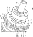
FIG. 7 depicts a plan view of still another portion of the no-back device of FIG. 1 more clearly illustrating certain other interface features; -
FIGS. 8(a)-8(c) depict one configuration of a groove pair that may be used to configure the no-back device of FIG. 1 for bidirectional operation; and -
FIGS. 9(a)-9(c) depict one configuration of a groove pair that may be used to configure the no-back device of FIG. 1 for unidirectional operation. - The following detailed description is merely exemplary in nature and is not intended to limit the invention or the application and uses of the invention. As used herein, the word "exemplary" means "serving as an example, instance, or illustration." Thus, any embodiment described herein as "exemplary" is not necessarily to be construed as preferred or advantageous over other embodiments. All of the embodiments described herein are exemplary embodiments provided to enable persons skilled in the art to make or use the invention and not to limit the scope of the invention which is defined by the claims. Furthermore, there is no intention to be bound by any expressed or implied theory presented in the preceding technical field, background, brief summary, or the following detailed description.
- Referring to FIG. 1, a cross section view of one embodiment of a self-activated no-
back device 100 is depicted. The depicteddevice 100 includes ahousing 102, aninput shaft 104, anoutput shaft 106, areactor hub 108, a plurality ofballs 110, abrake hub 112, areactor plate 114, and abrake pack 116. Thehousing 102, at least in the depicted embodiment, is an assembly of various parts but could, in other embodiments, be cast as a single component. - The
input shaft 104 and theoutput shaft 106 are both rotationally mounted on thehousing 102. In the depicted embodiment, theinput shaft 104 is rotationally mounted on thehousing 102 via afirst bearing assembly 105, and theoutput shaft 106 is rotationally mounted on thehousing 102 via asecond bearing assembly 107. No matter how theinput shaft 104 andoutput shaft 106 are rotationally mounted, theinput shaft 104 is adapted to receive an input drive torque, and theoutput shaft 106 is adapted to receive an output load torque. It will be appreciated that the input drive torque supplied to theinput shaft 104 may be supplied from any one of numerous types of non-illustrated devices that are operable to supply a drive torque. It will additionally be appreciated that the output load torque may be supplied to theoutput shaft 106 from any one of numerous types of non-illustrated loads that are operable to supply a torque to theoutput shaft 106. - Regardless of the specific sources of the input drive torque and the output load torque, the
input shaft 104 andoutput shaft 106 are configured such that theoutput shaft 106 is selectively engaged with theinput shaft 104. To implement this functionality, and asFIG. 2 depicts more clearly, theinput shaft 104 includes an input shaftfirst end 202 and an input shaftsecond end 204, and theoutput shaft 106 includes an output shaftfirst end 206 and an output shaftsecond end 208. Theinput shaft 104 and theoutput shaft 106 also each include a plurality of drive dogs. In particular, the input shaftsecond end 204 includes a plurality of input shaft drive dogs 212 (only one visible inFIG. 2 ) and the output shaftfirst end 206 includes a plurality of output shaft drive dogs 214. - The input shaft drive dogs 212 are spaced apart from each other by a first predetermined arc length to define a plurality of
first gaps 216, and the output shaft drive dogs 214 are spaced apart from each other by a second predetermined arc length to define a plurality of second gaps 218 (only one visible inFIG. 2 ). AsFIG. 2 also depicts, each inputshaft drive dog 212 is disposed within a different one of thesecond gaps 218, and each outputshaft drive dog 214 is disposed within a different one of thefirst gaps 216. Thefirst gaps 216 and thesecond gaps 218 are dimensioned to allow a predetermined amount of relative rotation between theinput shaft 104 and theoutput shaft 106. Although the depicted embodiment includes two input shaft drive dogs 212 and two output shaft drive dogs 214 and thus twofirst gaps 216 and twosecond gaps 218, it will be appreciated that theinput shaft 104 andoutput shaft 106 could include more than this number of input shaft drive dogs 212 and output shaft drive dogs 214, respectively. - Returning now to FIG. 1, the
reactor hub 108 surrounds a portion of theinput shaft 104 and has a reactorhub exterior side 118 and a reactor hubinterior side 122. A plurality offirst grooves 124 are formed in the reactor hubinterior side 122. Although only onefirst groove 124 is visible in FIG. 1, the plurality offirst grooves 124 are visible inFIG. 3 , which depicts both thereactor hub 108 andbrake hub 112 in ghosted form. As will be described in more detail further below, each of thefirst grooves 124 has at least onefirst cam surface 125. - The
reactor hub 108 is selectively rotatable with theinput shaft 104. That is, at times, a predetermined amount of relative rotation may occur between theinput shaft 104 andreactor hub 108. To implement this, it is seen that thereactor hub 108, at least in the depicted embodiment, includes a reactor hubcylindrical portion 126 that extends axially from the reactorhub exterior side 118. The reactor hubcylindrical portion 126 has aninner surface 128 and anouter surface 132. Theinner surface 128 defines aninput shaft opening 134 through which theinput shaft 104 extends. As shown more clearly inFIGS. 3 and4 , theinner surface 128 also has akey pocket 402 formed therein. Additionally, theinput shaft 104 includes aninput shaft key 404 that protrudes radially therefrom. Theinput shaft key 404 is disposed within thekey pocket 402. Thekey pocket 402 and theinput shaft key 404 are dimensioned to allow the predetermined amount of relative rotation between theinput shaft 104 and thereactor hub 108. The purpose for this will be described further below. - Returning again to FIG. 1, the
brake hub 112 is mounted on, and is rotatable with, theoutput shaft 106 and has a brakehub exterior side 136 and a brake hubinterior side 138. A plurality ofsecond grooves 142 are formed in the brake hub interior side. Although only onesecond groove 142 is visible in FIG. 1, the plurality ofsecond grooves 124 are visible inFIG. 3 . AsFIG. 3 also depicts, each of thesecond grooves 142 is aligned with a different one of thefirst grooves 124 to define a plurality of groove pairs. As will also be described further below, each of thesecond grooves 142 has asecond cam surface 143. - Although the
brake hub 112 is rotatable with theoutput shaft 106, it is also axially movable relative to theoutput shaft 106. To implement this, thebrake hub 112 includes a brake hubcylindrical portion 144 that extends axially from the brakehub exterior surface 136. The brake hubcylindrical portion 144 hasinner surface 146 and anouter surface 148. Theinner surface 146 defines anoutput shaft opening 152 through which theoutput shaft 106 extends. As shown more clearly inFIG. 5 , theinner surface 146 has a plurality ofgrooves 502 formed therein, and theoutput shaft 106 has a plurality ofsplines 504 formed on a portion thereof. Eachspline 504 is disposed within a different one of thegrooves 502 and allows thebrake hub 112 to move axially relative to theoutput shaft 106. Although twogrooves 502 and twosplines 504 are depicted, it will be appreciated that thebrake hub 112 andoutput shaft 106 could include more than this number ofgrooves 502 andsplines 504, respectively. - Returning again to FIG. 1, the
reactor plate 114 is mounted within thehousing 102 and has a reactor plateinterior side 154 and a reactorplate exterior side 156. The reactor plateinterior side 154 contacts thereactor hub 108, and more specifically the reactorhub exterior side 118, and supplies a continuous friction force to thereactor hub 108. In the depicted embodiment, areactor spring 158, which is mounted within the housing, supplies a first spring force to thereactor plate 114, which causes thereactor plate 114 to contact thereactor hub 108. One embodiment of thereactor spring 158 is shown even more clearly inFIG. 4 . - The
brake pack 116 is mounted within thehousing 102 and is selectively contacted by the brakehub exterior side 136, and thus stops the rotation of thebrake hub 112 and, concomitantly, theoutput shaft 106. Although thebrake pack 116 may be variously configured and implemented, in the depicted embodiment thebrake pack 116 includes a plurality ofbrake plates 162 and a plurality ofbrake discs 164. Eachbrake disc 164 is disposed between, and continuously contacts, a different pair of the plurality ofbrake plates 162. Aload spring 166, which is mounted within thehousing 102, supplies a second spring force to thebrake pack 116, which causes eachbrake disc 164 to continuously contact the different pair ofbrake plates 162. One embodiment of theload spring 166 is shown even more clearly inFIG. 5 . - In addition to the above, it is noted that each
brake plate 162 is non-rotationally mounted in thehousing 102 and is axially movable relative to thehousing 102. Moreover, eachbrake disc 164 is mounted on, and is rotatable with, thebrake hub 112, while also being axially movable relative to thebrake hub 112. To implement this, and as shown more clearly inFIGS. 6 and7 , eachbrake plate 162 has a plurality ofprotrusions 602 extending radially therefrom, and eachprotrusion 602 is disposed within a different one of a plurality ofhousing grooves 604 that are formed in a portion of aninner surface 606 of thehousing 102. Additionally, eachbrake disc 164 has a plurality ofbrake disc grooves 702 formed therein, and theouter surface 148 of the brake hubcylindrical portion 144 has a plurality ofsplines 704 formed on a portion thereof. Each of thesplines 704 is disposed within a different one of thebrake disc grooves 702 and allows thebrake discs 164 to move axially relative to thebrake hub 112. - It was previously noted that each of the
first grooves 124 has at least onefirst cam surface 125, and that each of thesecond grooves 142 has at least onesecond cam surface 143. It was also noted that each of thesecond grooves 142 is aligned with a different one of thefirst grooves 124 to define a plurality of groove pairs. It should be noted that although sixfirst grooves 124 and sixsecond grooves 142 are included in the depicted embodiment, this number ofgrooves reactor hub 108 andbrake hub 112. Additionally, while thereactor hub 108 andbrake hub 112 are depicted as having the same number ofgrooves hub reactor hub 108 has at least twofirst grooves 124 that are substantially aligned with twosecond grooves 142 on thebrake hub 112, to define two groove pairs. - No matter the number of first and
second grooves balls 110 are disposed. In particular, as FIGS. 1 and3 depict, eachball 110 is positioned in a different one of the groove pairs. The nominal position of eachball 110, which is the position depicted in FIGS. 1 and3 , is when eachball 110 is positioned at the lowest point of the first andsecond grooves balls 110 may be displaced along the first and second cam surfaces 125, 143. As will also be described momentarily, the brakehub exterior side 136 will contact thebrake pack 116 when theballs 110 are displaced a predetermined distance along the first and second cam surfaces 125, 143. - Before proceeding further, it was previously noted that the first and
second gaps input shaft 104 and theoutput shaft 106, and thatkey pocket 402 and theinput shaft key 404 are dimensioned to allow the predetermined amount of relative rotation between theinput shaft 104 and thereactor hub 108. It will be appreciated that these dimensions are such that when each ofballs 110 is in the nominal position, the input and output shaft drive dogs 212, 214 are in contact, and simultaneously thekey pocket 402 and theinput shaft key 404 are in contact. - The self-activated no-
back device 100 may be configured as a bidirectional device or as a unidirectional device, depending upon the configuration of the first and second cam surfaces 125, 143. When configured as a bidirectional device, the first and second cam surfaces 124, 142 allow theballs 110 to be displaced in two rotational directions. When configured as a unidirectional device, the first and second cam surfaces 125, 143 allow theballs 100 to be displaced in only one rotational direction. One example of the configuration of the first and second cam surfaces 125, 143 for bidirectional operation is depicted inFIGS. 8(a)-8(c) , and one example of the configuration of the first and second cam surfaces 125, 143 for unidirectional operation is depicted inFIGS. 9(a)-9(c) . AsFIGS. 8(a)-8(c) depict, for bidirectional operation, the first andsecond grooves cam surfaces FIGS. 9(a)-9(c) , for unidirectional operation, the first andsecond grooves cam surface second grooves second shoulder balls 110 to only a single direction. - Having described the structure of the self-activated no-
back device 100 in detail, a more detailed description of the operation of thedevice 100 will no be provided. In doing so, it is noted that thedevice 100, whether configured as a bidirectional or unidirectional device, is configured to operate in two different operating regimes - an actuation regime and a holding regime - each of which will now be described. - In the actuation regime, the
device 100 may freely rotate in both rotational directions when it is driven by the non-illustrated torque supply device (e.g., motor). That is, the torque supplied from the non-illustrated torque supply device (e.g., a motor) to theinput shaft 104 is transferred directly to the non-illustrated load via theoutput shaft 106. - More specifically, while operating in the actuation regime, the
balls 110 are in the nominal position. Thus, as mentioned above, the input and output shaft drive dogs 212, 214 are in contact, and simultaneously thekey pocket 402 and theinput shaft key 404 are in contact. This means that thereactor hub 108 rotates with theinput shaft 104, and the torque supplied to theinput shaft 104 is transferred to theoutput shaft 106. Because of the configuration of theoutput shaft 106, thebrake hub 112, and thebrake discs 116, the components rotate synchronously. Moreover, because theballs 110 are in the position, thebrake hub 112 is in its nominal position (see FIG. 1), which is defined by the preload of thereactor spring 158 and theload spring 166. - The
device 100 will operate in the holding regime when a torque supplied from the non-illustrated load exceeds the torque (if any) being supplied from the non-illustrated torque supply device by a predetermined amount. Thedevice 100 self-activates thebrake pack 116 and diverts the torque acting onoutput shaft 106 into thehousing 102. As a result, the torque is not transferred to inputshaft 104 and thus not back to the torque supply device. When configured for bidirectional operation, the holding regime is activated for both rotational directions of the external torque. When configured for unidirectional operation, the holding regime is activated only in one rotational direction. In the other rotational direction, the torque is allowed to pass through thedevice 100 and back-drive the torque supply device. Each of these different holding regimes will now be described in more detail - When a load torque supplied from the non-illustrated load exceeds the torque (if any) being supplied from the non-illustrated torque supply device by a predetermined amount, the limited relative rotation between the
input shaft 104 and thereactor hub 108 allows thereactor hub 108 to maintain its position. This is due to the friction induced by its contact withreactor plate 114. The rotation of theoutput shaft 106, and thus thebrake hub 112, causes thebrake hub 112 to rotate relative to thereactor hub 108. This causes a displacement of each of the groove pairs, which in turn causes theballs 110 to roll from the nominal positions (FIG. 8(a) ) along the cam surfaces 125, 143 (FIGS. 8(b) or 8(c) ). This, in turn, urges thebrake hub 112 axially away from thereactor hub 108. This axial displacement of thebrake hub 112 increases the friction in thebrake pack 116, reacts against the external torque. - It should be noted that during the transition from the actuation regime to the holding regime, the
output shaft 106 rotates in the direction of the load torque by a predetermined maximum rotational displacement. This maximum rotation can be controlled by the stiffness characteristics of theload spring 166 to induce the friction against external torque load. - When in the holding regime, if the torque supply device is commanded to start driving the
device 100 in the opposite direction of the load torque, thedevice 100 will be released from the holding regime. This is accomplished when the torque supplied from the torque supply device to theinput shaft 104 is transmitted, via the input and output shaft drive dogs 212, 214, to thebrake hub 112. This again causes thebrake hub 112 to rotate relative to thereactor hub 108, but in the opposite direction. This decreases the displacement of each of the groove pairs, which in turn causes theballs 110 to roll back to the nominal positions (FIG. 8(a) ). - When in the holding regime, if the torque supply device is commanded to start driving the
device 100 in the same direction as the load torque, the torque supplied to theinput shaft 104 is transferred to thereactor hub 108. This causes thereactor hub 108 to rotate relative to thebrake hub 112. This decreases the displacement of each of the groove pairs, which in turn causes theballs 110 to roll back to the nominal positions (FIG. 8(a) . Theload spring 166 moves thebrake hub 112 back to its nominal position, decreasing the preload of both thereactor spring 158 andload spring 166. The torque is then transmitted from theinput shaft 104 to theoutput shaft 106 through the drive dogs 212, 214. - If the load torque were to suddenly change its direction while the
device 100 is operating in the actuation regime and start acting in the same direction as torque supply device, it could cause theoutput shaft 106 to rotate faster than theinput shaft 104. This, too, would cause a displacement of each of the groove pairs, which in turn would cause theballs 110 to roll from the nominal positions (FIG. 8(a) ) along the cam surfaces 125, 143 (FIGS. 8(b) or 8(c) ). This would urge thebrake hub 112 axially away from thereactor hub 108 and increase the friction in thebrake pack 116. - When a load torque supplied from the non-illustrated load exceeds the torque (if any) being supplied from the non-illustrated torque supply device by a predetermined amount and in the particular direction in which the
device 100 is configured to hold the load, the operation of thedevice 100 is the same as for bidirectional operation. That is, the limited relative rotation between theinput shaft 104 and thereactor hub 108 allows thereactor hub 108 to maintain its position. This is due to the friction induced by its contact withreactor plate 114. The rotation of theoutput shaft 106, and thus thebrake hub 112, causes thebrake hub 112 to rotate relative to thereactor hub 108. This causes a displacement of each of the groove pairs, which in turn causes theballs 110 to roll from the nominal positions (FIG. 9(a) ) along the cam surfaces 125, 143 (FIG. 9(c) ). This, in turn, urges thebrake hub 112 axially away from thereactor hub 108. This axial displacement of thebrake hub 112 increases the friction in thebrake pack 116, reacts against the external torque. - As with the bidirectional operation, during the transition from the actuation regime to the holding regime, the
output shaft 106 rotates in the direction of the load torque by a predetermined maximum rotational displacement. This maximum rotation can be controlled by the stiffness characteristics of theload spring 166 to induce the friction against external torque load. - When in the holding regime, if the torque supply device is commanded to start driving the
device 100 in the opposite direction of the load torque, thedevice 100 will be released from the holding regime. This is accomplished when the torque supplied from the torque supply device to theinput shaft 104 is transmitted, via the input and output shaft drive dogs 212, 214, to thebrake hub 112. This again causes thebrake hub 112 to rotate relative to thereactor hub 108, but in the opposite direction. This decreases the displacement of each of the groove pairs, which in turn causes theballs 110 to roll back to the nominal positions (FIG. 9(a) ). - When in the holding regime, if the torque supply device is commanded to start driving the
device 100 in the same direction as the load torque, the torque supplied to theinput shaft 104 is transferred to thereactor hub 108. This causes thereactor hub 108 to rotate relative to thebrake hub 112. This decreases the displacement of each of the groove pairs, which in turn causes theballs 110 to roll back to the nominal positions (FIG. 8(a) . Theload spring 166 moves thebrake hub 112 back to its nominal position, decreasing the preload of both thereactor spring 158 andload spring 166. The torque is then transmitted from theinput shaft 104 to theoutput shaft 106. - If a load torque is supplied to the device in a direction in which back-driving is allowed (see
FIG. 9(b) ), theballs 110 contact the first andsecond shoulder reactor hub 108, which begins rotating when it overcomes the friction of thereactor plate 114. Simultaneously, because the input and output shaft drive dogs 212, 214 are engaged, the load torque is transferred through theinput shaft 104 to the torque supply device. - The self-activated no-
back device 100 described herein is not susceptible to chatter or ratcheting and/or is relatively simple and lightweight and/or accommodates relatively large back driving torques. It can also be configured for unidirectional or bidirectional operation. - In this document, relational terms such as first and second, and the like may be used solely to distinguish one entity or action from another entity or action without necessarily requiring or implying any actual such relationship or order between such entities or actions. Numerical ordinals such as "first," "second," "third," etc. simply denote different singles of a plurality and do not imply any order or sequence unless specifically defined by the claim language. The sequence of the text in any of the claims does not imply that process steps must be performed in a temporal or logical order according to such sequence unless it is specifically defined by the language of the claim. The process steps may be interchanged in any order without departing from the scope of the invention as long as such an interchange does not contradict the claim language and is not logically nonsensical.
- Furthermore, depending on the context, words such as "connect" or "coupled to" used in describing a relationship between different elements do not imply that a direct physical connection must be made between these elements. For example, two elements may be connected to each other physically, electronically, logically, or in any other manner, through one or more additional elements.
- As used herein, the term "axial" refers to a direction that is generally parallel to or coincident with an axis of rotation, axis of symmetry, or centerline of a component or components. For example, in a cylinder or disc with a centerline and generally circular ends or opposing faces, the "axial" direction may refer to the direction that generally extends in parallel to the centerline between the opposite ends or faces. In certain instances, the term "axial" may be utilized with respect to components that are not cylindrical (or otherwise radially symmetric). For example, the "axial" direction for a rectangular housing containing a rotating shaft may be viewed as a direction that is generally parallel to or coincident with the rotational axis of the shaft. Furthermore, the term "radially" as used herein may refer to a direction or a relationship of components with respect to a line extending outward from a shared centerline, axis, or similar reference, for example in a plane of a cylinder or disc that is perpendicular to the centerline or axis. In certain instances, components may be viewed as "radially" aligned even though one or both of the components may not be cylindrical (or otherwise radially symmetric). Furthermore, the terms "axial" and "radial" (and any derivatives) may encompass directional relationships that are other than precisely aligned with (e.g., oblique to) the true axial and radial dimensions, provided the relationship is predominantly in the respective nominal axial or radial direction. As used herein, the term "substantially" denotes within 5% to account for manufacturing tolerances. Also, as used herein, the term "about" denotes within 5% to account for manufacturing tolerances.
- While at least one exemplary embodiment has been presented in the foregoing detailed description of the invention, it should be appreciated that a vast number of variations exist. It should also be appreciated that the exemplary embodiment or exemplary embodiments are only examples, and are not intended to limit the scope, applicability, or configuration of the invention in any way. Rather, the foregoing detailed description will provide those skilled in the art with a convenient road map for implementing an exemplary embodiment of the invention. It being understood that various changes may be made in the function and arrangement of elements described in an exemplary embodiment without departing from the scope of the invention as set forth in the appended claims.
Claims (12)
- A self-activated no-back device, comprising:a housing;an input shaft rotationally mounted on the housing and adapted to receive an input drive torque;an output shaft rotationally mounted on the housing, the output shaft selectively engaged with the input shaft and adapted to receive output load torque;a reactor hub surrounding a portion of the input shaft and selectively rotatable therewith, the reactor hub having a reactor hub exterior side and a reactor hub interior side;a plurality of first grooves formed in the reactor hub interior side, each of the first grooves having at least one first cam surface;a brake hub mounted on the output shaft and rotatable therewith, the brake hub having a brake hub exterior side and a brake hub interior side;a plurality of second grooves formed in the brake hub interior side, each of the second grooves having at least one second cam surface, and each of the second grooves aligned with a different one of the first grooves to define a plurality of groove pairs;a plurality of balls, each ball positioned in a different one of the groove pairs;a reactor plate mounted within the housing and having a reactor plate interior side and a reactor plate exterior side, the reactor plate interior side contacting the reactor hub;a brake pack mounted within the housing and selectively contacted by the brake hub exterior side;a reactor spring mounted within the housing and supplying a first spring force to the reactor plate; anda load spring mounted within the housing and supplying a second spring force to the brake pack.
- The device of claim 1, wherein the brake hub exterior side contacts the brake pack when the balls are displaced a predetermined distance along the at least one first and second cam surfaces.
- The device of claim 2, wherein the at least one first and second cam surfaces allow the balls to be displaced in only one rotational direction.
- The device of claim 2, wherein the at least one first and second cam surfaces allow the balls to be displaced in two rotational directions.
- The device of claim 1, wherein:the input shaft includes an input shaft first end and an input shaft second end, the input shaft second end including a plurality of input shaft drive dogs, each input shaft drive dog spaced apart from each other by a first predetermined arc length to define a plurality of first gaps;the output shaft includes an output shaft first end and an output shaft second end, the output shaft first end including a plurality of output shaft drive dogs, each output shaft drive dog spaced apart from each other by a second predetermined arc length to define a plurality of second gaps;each input shaft drive dog is disposed within a different one of the second gaps; andeach output shaft drive dog is disposed within a different one of the first gaps.
- The device of claim 5, wherein the first gaps and the second gaps are dimensioned to allow a predetermined amount of relative rotation between the input shaft and the output shaft.
- The device of claim 1, wherein:the reactor hub includes a reactor hub cylindrical portion that extends axially from the reactor hub exterior side, the reactor hub cylindrical portion having an inner surface and an outer surface, the inner surface defining an input shaft opening through which the input shaft extends, the inner surface having a key pocket formed therein; andthe input shaft includes an input shaft key, the input shaft key protruding radially from the input shaft and disposed within the key pocket, whereby the reactor hub may move axially relative to the input shaft.
- The device of claim 7, wherein the key pocket and the input shaft key are dimensioned to allow a predetermined amount of relative rotation between the input shaft and the reactor hub.
- The device of claim 1, wherein:the brake hub includes a brake hub cylindrical portion that extends axially from the brake hub exterior side, the brake hub cylindrical portion having inner surface and an outer surface, the inner surface defining an output shaft opening through which the output shaft extends, the inner surface having a plurality of grooves formed therein; andthe output shaft has a plurality of splines formed on a portion thereof, each spline disposed within a different one of the grooves, whereby the brake hub may move axially relative to the output shaft.
- The device of claim 1, wherein:the brake pack comprises a plurality of brake plates and a plurality of brake discs; andeach brake disc is disposed between, and contacts, a different pair of the plurality of brake plates.
- The device of claim 10, wherein:each brake plate is non-rotationally mounted in the housing and is axially movable relative to the housing; andeach brake disc is mounted on, and is rotatable with, the brake hub.
- The device of claim 11, wherein each brake disc is axially movable relative to the brake hub.
Applications Claiming Priority (1)
| Application Number | Priority Date | Filing Date | Title |
|---|---|---|---|
| US17/497,396 US11906006B2 (en) | 2021-10-08 | 2021-10-08 | Self-activated no-back device |
Publications (1)
| Publication Number | Publication Date |
|---|---|
| EP4166809A1 true EP4166809A1 (en) | 2023-04-19 |
Family
ID=83398218
Family Applications (1)
| Application Number | Title | Priority Date | Filing Date |
|---|---|---|---|
| EP22196665.8A Withdrawn EP4166809A1 (en) | 2021-10-08 | 2022-09-20 | Self-activated no-back device |
Country Status (2)
| Country | Link |
|---|---|
| US (1) | US11906006B2 (en) |
| EP (1) | EP4166809A1 (en) |
Cited By (1)
| Publication number | Priority date | Publication date | Assignee | Title |
|---|---|---|---|---|
| EP4520659A1 (en) * | 2023-09-05 | 2025-03-12 | The Boeing Company | No-back brake having a limited authority damper |
Citations (1)
| Publication number | Priority date | Publication date | Assignee | Title |
|---|---|---|---|---|
| US4693349A (en) * | 1986-07-25 | 1987-09-15 | Sundstrand Corporation | Torque limiting apparatus |
Family Cites Families (24)
| Publication number | Priority date | Publication date | Assignee | Title |
|---|---|---|---|---|
| US3011605A (en) | 1958-07-24 | 1961-12-05 | Curtiss Wright Corp | No-back coupling mechanism |
| US3119480A (en) | 1961-04-13 | 1964-01-28 | Airborne Accessories Corp | Bi-directional, no-back transmissions |
| US3201086A (en) | 1963-02-28 | 1965-08-17 | Westran Corp | No-back device for semi-trailer landing gear legs and the like |
| US3335831A (en) | 1965-10-23 | 1967-08-15 | Formsprag Co | Bi-directional no-back drive device |
| US3667578A (en) | 1971-05-14 | 1972-06-06 | Harold Beck & Sons Inc | Bi-directional drive released brake |
| US4176733A (en) * | 1978-04-26 | 1979-12-04 | Sundstrand Corporation | Combination no-back brake and torque limiter assembly |
| US4480733A (en) | 1981-05-04 | 1984-11-06 | Sundstrand Corporation | Energy absorbing bidirectional ratchet no-back apparatus |
| US4579201A (en) | 1983-05-16 | 1986-04-01 | Curtiss Wright Flight Systems, Inc. | Bidirectional, torque-limiting, no-back clutch mechanism |
| US4597477A (en) * | 1984-04-16 | 1986-07-01 | Sundstrand Corporation | Bidirectional brake |
| US4850458A (en) | 1988-11-16 | 1989-07-25 | Boeing Company | Bidirectional rotary brake |
| US20020101106A1 (en) | 2001-02-01 | 2002-08-01 | Kim Stephen E. | No-back drive mechanism for use with aircraft seat actuators |
| US6666307B1 (en) | 2002-08-05 | 2003-12-23 | Honeywell International, Inc. | Thrust reverser system with a pass-through torque activated brake |
| JP4483412B2 (en) | 2003-10-22 | 2010-06-16 | 株式会社島津製作所 | Torque limiter |
| US6974015B2 (en) | 2004-03-09 | 2005-12-13 | The Carlyle Johnson Machine Company, Llc | One-way bidirectional clutch |
| US8511441B2 (en) | 2010-04-01 | 2013-08-20 | Hamilton Sundstrand Corporation | Cone brake no-back |
| DE112011103981A5 (en) | 2010-11-30 | 2013-09-26 | Magna Powertrain Ag & Co. Kg | actuator |
| US9255632B2 (en) | 2012-05-23 | 2016-02-09 | Hamilton Sundstrand Corporation | Integrated torque limiter/no-back device |
| US8978840B2 (en) * | 2012-11-19 | 2015-03-17 | Hamilton Sundstrand Corporation | Asymmetry brake with torque limit |
| US9527580B2 (en) | 2014-09-24 | 2016-12-27 | Hamilton Sundstrand Corporation | Cone brake no-back assembly with gain reduction spring and method |
| US9416832B1 (en) * | 2015-02-02 | 2016-08-16 | The Boeing Company | Half system torque brakes |
| EP3078589B1 (en) | 2015-04-09 | 2018-01-24 | Goodrich Actuation Systems SAS | No-back device for flight control surface actuator |
| DE102017129235A1 (en) | 2017-12-08 | 2019-06-13 | Liebherr-Aerospace Lindenberg Gmbh | Dynamic return brake with damping element |
| US10935115B2 (en) | 2018-08-20 | 2021-03-02 | Hamilton Sunstrand Corporation | Linear actuator with testable cone no-back and torque limiter |
| US11440640B2 (en) | 2018-12-18 | 2022-09-13 | The Boeing Company | Bi-directional no-back brake progressive modulation spring systems and methods |
-
2021
- 2021-10-08 US US17/497,396 patent/US11906006B2/en active Active
-
2022
- 2022-09-20 EP EP22196665.8A patent/EP4166809A1/en not_active Withdrawn
Patent Citations (1)
| Publication number | Priority date | Publication date | Assignee | Title |
|---|---|---|---|---|
| US4693349A (en) * | 1986-07-25 | 1987-09-15 | Sundstrand Corporation | Torque limiting apparatus |
Cited By (1)
| Publication number | Priority date | Publication date | Assignee | Title |
|---|---|---|---|---|
| EP4520659A1 (en) * | 2023-09-05 | 2025-03-12 | The Boeing Company | No-back brake having a limited authority damper |
Also Published As
| Publication number | Publication date |
|---|---|
| US11906006B2 (en) | 2024-02-20 |
| US20230115546A1 (en) | 2023-04-13 |
Similar Documents
| Publication | Publication Date | Title |
|---|---|---|
| US4603594A (en) | Fail safe actuator | |
| US10018258B2 (en) | Actuator having an associated locking device and torque limiter | |
| EP2885560B1 (en) | Torque limiting differential | |
| US9657827B2 (en) | Torque limiting differential | |
| RU2619742C2 (en) | Differential lock with small stroke length and with large length of locking links | |
| EP2602511B1 (en) | Actuator | |
| US3542162A (en) | Torque limiting device | |
| EP2371709A2 (en) | Cone brake no-back | |
| CN112334680A (en) | Rotor cam and clutch device using rotor cam | |
| JP2001074077A (en) | Energy absorbing brake | |
| EP2581618A2 (en) | Clutch device | |
| US20140135132A1 (en) | Non-chattering ball detent torque limiter | |
| US11906006B2 (en) | Self-activated no-back device | |
| EP4130502B1 (en) | Power assembly and vehicle | |
| CA2912965C (en) | Shock absorber assembly for power drive unit of a vehicle | |
| US4721196A (en) | Overtravel stop | |
| US20030051950A1 (en) | Braking assembly | |
| CN105443612B (en) | Controllable bidirectional check controller, controllable bidirectional non-return device and check deceleration device | |
| CN112313422B (en) | Clutch device | |
| US8151958B2 (en) | Power transmitting device | |
| EP3961057A1 (en) | A clutch, industrial robot and the use thereof | |
| US20050087419A1 (en) | Torque limiter | |
| GB2136526A (en) | Friction brake incorporating a ball and ramp drive mechanism | |
| US11274712B2 (en) | Overload clutch for a drive gear mechanism for driving components of an aircraft wing and drive gear mechanism with an overload clutch | |
| EP4105090B1 (en) | Braking device |
Legal Events
| Date | Code | Title | Description |
|---|---|---|---|
| PUAI | Public reference made under article 153(3) epc to a published international application that has entered the european phase |
Free format text: ORIGINAL CODE: 0009012 |
|
| STAA | Information on the status of an ep patent application or granted ep patent |
Free format text: STATUS: THE APPLICATION HAS BEEN PUBLISHED |
|
| AK | Designated contracting states |
Kind code of ref document: A1 Designated state(s): AL AT BE BG CH CY CZ DE DK EE ES FI FR GB GR HR HU IE IS IT LI LT LU LV MC MK MT NL NO PL PT RO RS SE SI SK SM TR |
|
| P01 | Opt-out of the competence of the unified patent court (upc) registered |
Effective date: 20230525 |
|
| STAA | Information on the status of an ep patent application or granted ep patent |
Free format text: STATUS: THE APPLICATION IS DEEMED TO BE WITHDRAWN |
|
| 18D | Application deemed to be withdrawn |
Effective date: 20231020 |