EP4166530A1 - Liquid fuel synthesis system - Google Patents
Liquid fuel synthesis system Download PDFInfo
- Publication number
- EP4166530A1 EP4166530A1 EP22820239.6A EP22820239A EP4166530A1 EP 4166530 A1 EP4166530 A1 EP 4166530A1 EP 22820239 A EP22820239 A EP 22820239A EP 4166530 A1 EP4166530 A1 EP 4166530A1
- Authority
- EP
- European Patent Office
- Prior art keywords
- permeation side
- liquid fuel
- side space
- temperature
- separation membrane
- Prior art date
- Legal status (The legal status is an assumption and is not a legal conclusion. Google has not performed a legal analysis and makes no representation as to the accuracy of the status listed.)
- Granted
Links
Images




Classifications
-
- B—PERFORMING OPERATIONS; TRANSPORTING
- B01—PHYSICAL OR CHEMICAL PROCESSES OR APPARATUS IN GENERAL
- B01D—SEPARATION
- B01D53/00—Separation of gases or vapours; Recovering vapours of volatile solvents from gases; Chemical or biological purification of waste gases, e.g. engine exhaust gases, smoke, fumes, flue gases, aerosols
- B01D53/22—Separation of gases or vapours; Recovering vapours of volatile solvents from gases; Chemical or biological purification of waste gases, e.g. engine exhaust gases, smoke, fumes, flue gases, aerosols by diffusion
-
- C—CHEMISTRY; METALLURGY
- C10—PETROLEUM, GAS OR COKE INDUSTRIES; TECHNICAL GASES CONTAINING CARBON MONOXIDE; FUELS; LUBRICANTS; PEAT
- C10G—CRACKING HYDROCARBON OILS; PRODUCTION OF LIQUID HYDROCARBON MIXTURES, e.g. BY DESTRUCTIVE HYDROGENATION, OLIGOMERISATION, POLYMERISATION; RECOVERY OF HYDROCARBON OILS FROM OIL-SHALE, OIL-SAND, OR GASES; REFINING MIXTURES MAINLY CONSISTING OF HYDROCARBONS; REFORMING OF NAPHTHA; MINERAL WAXES
- C10G2/00—Production of liquid hydrocarbon mixtures of undefined composition from oxides of carbon
-
- B—PERFORMING OPERATIONS; TRANSPORTING
- B01—PHYSICAL OR CHEMICAL PROCESSES OR APPARATUS IN GENERAL
- B01D—SEPARATION
- B01D53/00—Separation of gases or vapours; Recovering vapours of volatile solvents from gases; Chemical or biological purification of waste gases, e.g. engine exhaust gases, smoke, fumes, flue gases, aerosols
- B01D53/26—Drying gases or vapours
- B01D53/268—Drying gases or vapours by diffusion
-
- B—PERFORMING OPERATIONS; TRANSPORTING
- B01—PHYSICAL OR CHEMICAL PROCESSES OR APPARATUS IN GENERAL
- B01D—SEPARATION
- B01D61/00—Processes of separation using semi-permeable membranes, e.g. dialysis, osmosis or ultrafiltration; Apparatus, accessories or auxiliary operations specially adapted therefor
- B01D61/36—Pervaporation; Membrane distillation; Liquid permeation
-
- B—PERFORMING OPERATIONS; TRANSPORTING
- B01—PHYSICAL OR CHEMICAL PROCESSES OR APPARATUS IN GENERAL
- B01D—SEPARATION
- B01D63/00—Apparatus in general for separation processes using semi-permeable membranes
- B01D63/06—Tubular membrane modules
-
- B—PERFORMING OPERATIONS; TRANSPORTING
- B01—PHYSICAL OR CHEMICAL PROCESSES OR APPARATUS IN GENERAL
- B01J—CHEMICAL OR PHYSICAL PROCESSES, e.g. CATALYSIS OR COLLOID CHEMISTRY; THEIR RELEVANT APPARATUS
- B01J19/00—Chemical, physical or physico-chemical processes in general; Their relevant apparatus
- B01J19/24—Stationary reactors without moving elements inside
- B01J19/2475—Membrane reactors
-
- C—CHEMISTRY; METALLURGY
- C01—INORGANIC CHEMISTRY
- C01B—NON-METALLIC ELEMENTS; COMPOUNDS THEREOF; METALLOIDS OR COMPOUNDS THEREOF NOT COVERED BY SUBCLASS C01C
- C01B3/00—Hydrogen; Gaseous mixtures containing hydrogen; Separation of hydrogen from mixtures containing it; Purification of hydrogen; Reversible storage of hydrogen
- C01B3/50—Separation of hydrogen or hydrogen-containing gases from gaseous mixtures, e.g. purification
- C01B3/501—Separation of hydrogen or hydrogen-containing gases from gaseous mixtures, e.g. purification by diffusion
- C01B3/503—Separation of hydrogen or hydrogen-containing gases from gaseous mixtures, e.g. purification by diffusion characterised by membranes
-
- C—CHEMISTRY; METALLURGY
- C10—PETROLEUM, GAS OR COKE INDUSTRIES; TECHNICAL GASES CONTAINING CARBON MONOXIDE; FUELS; LUBRICANTS; PEAT
- C10G—CRACKING HYDROCARBON OILS; PRODUCTION OF LIQUID HYDROCARBON MIXTURES, e.g. BY DESTRUCTIVE HYDROGENATION, OLIGOMERISATION, POLYMERISATION; RECOVERY OF HYDROCARBON OILS FROM OIL-SHALE, OIL-SAND, OR GASES; REFINING MIXTURES MAINLY CONSISTING OF HYDROCARBONS; REFORMING OF NAPHTHA; MINERAL WAXES
- C10G31/00—Refining of hydrocarbon oils, in the absence of hydrogen, by methods not otherwise provided for
- C10G31/11—Refining of hydrocarbon oils, in the absence of hydrogen, by methods not otherwise provided for by dialysis
-
- C—CHEMISTRY; METALLURGY
- C01—INORGANIC CHEMISTRY
- C01B—NON-METALLIC ELEMENTS; COMPOUNDS THEREOF; METALLOIDS OR COMPOUNDS THEREOF NOT COVERED BY SUBCLASS C01C
- C01B2203/00—Integrated processes for the production of hydrogen or synthesis gas
- C01B2203/04—Integrated processes for the production of hydrogen or synthesis gas containing a purification step for the hydrogen or the synthesis gas
- C01B2203/0405—Purification by membrane separation
Definitions
- the permeation side space 110B is disposed on a permeation side of the separation membrane 3.
- the water vapor permeating through the separation membrane 3 flows into the permeation side space 110B.
- a sweep gas is supplied from the sweep gas supply unit 130 to the permeation side space 110B.
- the sweep gas flows into the permeation side space 110B through an inflow port b1.
- a second outflow gas containing the sweep gas and the water vapor flows out of the permeation side space 110B through an outflow port b2.
- the average pore diameter of the buffer layer 22 is preferably smaller than the average pore diameter of the catalyst layer 21, and can be, for example, 0.001 pm or more and 2 pm or less.
- the average pore diameter of the buffer layer 22 can be measured using a Perm Porometer.
- the porosity of the buffer layer 22 can be 20% or more and 60% or less.
- the average particle size of the porous material forming the buffer layer 22 is preferably smaller than the average particle size of the porous material forming the catalyst layer 21, and can be, for example, 0.01 pm or more and 20 pm or less.
Landscapes
- Chemical & Material Sciences (AREA)
- Engineering & Computer Science (AREA)
- Chemical Kinetics & Catalysis (AREA)
- Oil, Petroleum & Natural Gas (AREA)
- Organic Chemistry (AREA)
- General Chemical & Material Sciences (AREA)
- Water Supply & Treatment (AREA)
- Analytical Chemistry (AREA)
- Inorganic Chemistry (AREA)
- Combustion & Propulsion (AREA)
- Separation Using Semi-Permeable Membranes (AREA)
- Organic Low-Molecular-Weight Compounds And Preparation Thereof (AREA)
- Liquid Carbonaceous Fuels (AREA)
- Production Of Liquid Hydrocarbon Mixture For Refining Petroleum (AREA)
Abstract
Description
- The present invention relates to a liquid fuel synthesis system.
- In recent years, liquid fuel synthesis systems have been developed that can improve, in a conversion reaction of a raw material gas containing hydrogen and carbon oxide (carbon monoxide, carbon dioxide, or the like) to a liquid fuel (a fuel such as methanol that is in a liquid state at normal temperature and pressure), conversion efficiency by separating water vapor which is a by-product.
-
Patent Literature 1 discloses a liquid fuel synthesis system including a membrane reactor, a raw material gas supply unit, and a sweep gas supply unit. The membrane reactor includes a catalyst for promoting the conversion reaction of a raw material gas containing carbon dioxide and hydrogen into methanol, and a separation membrane permeable to water vapor which is a by-product of the conversion reaction. The raw material gas supply unit supplies the raw material gas to a non-permeation side of the separation membrane. The sweep gas supply unit supplies a sweep gas to a permeation side of the separation membrane. Water vapor that has permeated through the separation membrane is discharged from the membrane reactor together with the sweep gas. - Patent Literature 1:
JP 2018-008940A - However, in the liquid fuel synthesis system described in
Patent Literature 1, the pressure and temperature of the water vapor permeating through the separation membrane are reduced, and relative humidity on the permeation side of the separation membrane increases, which may reduce durability of the separation membrane. Such problems are significant if the separation membrane is easily decomposed in a high temperature and high humidity environment. - The present invention has been made in view of the above circumstances, and an object of the present invention is to provide a liquid fuel synthesis system capable of suppressing reduction in durability of the separation membrane.
- A liquid fuel synthesis system according to a first aspect includes a liquid fuel synthesis portion and a sweep gas supply unit. The liquid fuel synthesis portion has a separation membrane permeable to water vapor which is a by-product of a conversion reaction of a raw material gas containing hydrogen and carbon oxide to a liquid fuel. The liquid fuel synthesis portion is partitioned into a non-permeation side space and a permeation side space by the separation membrane. The sweep gas supply unit is configured to supply the permeation side space with a sweep gas for sweeping the water vapor permeating through the separation membrane. A temperature of the sweep gas flowing into the permeation side space is higher than at least one of a temperature of the raw material gas flowing into the non-permeation side space and a temperature of a first outflow gas flowing out of the non-permeation side space. A temperature of a second outflow gas flowing out of the permeation side space is higher than at least one of the temperature of the raw material gas flowing into the non-permeation side space and the temperature of the first outflow gas flowing out of the non-permeation side space.
- A liquid fuel synthesis system according to a second aspect includes a liquid fuel synthesis portion and a sweep gas supply unit. The liquid fuel synthesis portion has a separation membrane permeable to a liquid fuel which is a product of a conversion reaction of a raw material gas containing hydrogen and carbon oxide to the liquid fuel, and water vapor which is a by-product of the conversion reaction. The liquid fuel synthesis portion is partitioned into a non-permeation side space and a permeation side space by the separation membrane. The sweep gas supply unit is configured to supply the permeation side space with a sweep gas for sweeping the liquid fuel permeating through the separation membrane. A temperature of the sweep gas flowing into the permeation side space is higher than at least one of a temperature of the raw material gas flowing into the non-permeation side space and a temperature of a first outflow gas flowing out of the non-permeation side space. A temperature of a second outflow gas flowing out of the permeation side space is higher than at least one of the temperature of the raw material gas flowing into the non-permeation side space and the temperature of the first outflow gas flowing out of the non-permeation side sp ace.
- In the liquid fuel synthesis system of a third aspect according to the first or second aspect, the temperature of the sweep gas flowing into the permeation side space is 150°C or higher and 450°C or lower.
- In the liquid fuel synthesis system of a fourth aspect according to the first or second aspect, the temperature of the sweep gas flowing into the permeation side space is 160°C or higher and 400°C or lower.
- In the liquid fuel synthesis system of a fifth aspect according to any one of the first to fourth aspects, the temperature of the raw material gas flowing into the non-permeation side space is 140°C or higher and 350°C or lower.
- According to the present invention, it is possible to provide a liquid fuel synthesis system capable of suppressing a reduction in durability of the separation membrane.
-
-
FIG. 1 is a schematic view showing a configuration of a liquid fuel synthesis system according to an embodiment. -
FIG. 2 is a perspective view of a membrane reactor according to the embodiment. -
FIG. 3 is a cross-sectional view taken along line A-A inFIG. 1 . -
FIG. 4 is a cross-sectional view of the membrane reactor according tomodification 3. -
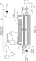
FIG. 5 is a schematic view showing the configuration of the liquid fuel synthesis system according tomodification 4. -
FIG. 6 is a schematic view showing the configuration of the liquid fuel synthesis system according tomodification 7. -
FIG. 7 is a schematic view showing the configuration of the liquid fuel synthesis system according tomodification 7. -
FIG. 8 is a schematic view showing the configuration of the liquid fuel synthesis system according tomodification 7. -
FIG. 9 is a schematic view showing the configuration of the liquid fuel synthesis system according tomodification 7. -
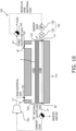
FIG. 10 is a schematic view showing the configuration of the liquid fuel synthesis system according tomodification 7. - Next, embodiments of the present invention will be described with reference to the drawings. However, the drawings are schematic, and ratio or the like of dimensions may differ from an actual one.
-
FIG. 1 is a schematic view showing a configuration of a liquidfuel synthesis system 100. The liquidfuel synthesis system 100 includes a liquidfuel synthesis portion 110, a raw materialgas supply unit 120, a sweepgas supply unit 130, afirst drain trap 140, and asecond drain trap 150. - The liquid
fuel synthesis portion 110 is used to convert the raw material gas to a liquid fuel. The raw material gas contains hydrogen and carbon oxide. The carbon oxide includes, for example, carbon monoxide, carbon dioxide, and mixtures thereof. The liquid fuel may be any fuel that is in a liquid state at normal temperature and pressure, and examples of the liquid fuel include methanol, ethanol, liquid fuels represented by CnH2(m-2n) (m and n are integers less than 30), and mixtures thereof. - For example, reaction formulas for synthesizing methanol by catalytically hydrogenating a raw material gas containing carbon monoxide, carbon dioxide and hydrogen in the presence of a catalyst are as follows.
CO + 2H2 ⇔ CH3OH (1)
CO2 + 3H2 ⇔ CH3OH + H2O (2)
CO2 + H2 ⇔ CO + H2O (3)
- All of the above reactions are equilibrium reactions, and in order to increase both the conversion rate and the reaction rate, it is preferable to carry out the reactions at a high temperature and high pressure (for example, 200°C or higher and 2 MPa or higher). The liquid fuel is in a gaseous state when it is synthesized, and is kept in a gaseous state at least until it flows out of the liquid
fuel synthesis portion 110. The liquidfuel synthesis portion 110 preferably has heat resistance and pressure resistance that correspond to production conditions of the liquid fuel. - The liquid
fuel synthesis portion 110 according to the present embodiment has aseparation membrane 3, anon-permeation side space 110A, and apermeation side space 110B. The liquidfuel synthesis portion 110 is partitioned by theseparation membrane 3 into thenon-permeation side space 110A and thepermeation side space 110B. - The
separation membrane 3 separates water vapor which is a by-product of a conversion reaction in which the raw material gas is converted to the liquid fuel. This allows an equilibrium shift effect to be exploited to further increase the conversion efficiency. By utilizing the equilibrium shift effect, a reaction equilibrium of the above formulas (1) to (3) can be shifted to the product side. - The non-permeation side space 110Ais disposed on a non-permeation side of the
separation membrane 3. In thenon-permeation side space 110A, the conversion reaction of the raw material gas to the liquid fuel proceeds. The raw material gas is supplied from the raw materialgas supply unit 120 to thenon-permeation side space 110A. The raw material gas flows into thenon-permeation side space 110A through an inflow port a1. A first outflow gas containing a synthesized gaseous liquid fuel flows out of thenon-permeation side space 110A through an outflow port a2. The first outflow gas flowing out of the outflow port a2 may contain unreacted residual raw material gas in addition to the liquid fuel. - The
permeation side space 110B is disposed on a permeation side of theseparation membrane 3. The water vapor permeating through theseparation membrane 3 flows into thepermeation side space 110B. A sweep gas is supplied from the sweepgas supply unit 130 to thepermeation side space 110B. The sweep gas flows into thepermeation side space 110B through an inflow port b1. A second outflow gas containing the sweep gas and the water vapor flows out of thepermeation side space 110B through an outflow port b2. - The raw material
gas supply unit 120 has astorage unit 121 and acompressor 122. Thestorage unit 121 stores the raw material gas. The raw material gas stored in thestorage unit 121 is pressurized by thecompressor 122 and then supplied to thenon-permeation side space 110A of the liquidfuel synthesis portion 110 through a line L1. - The sweep
gas supply unit 130 has astorage unit 131, apump 132, and aheating unit 133. Thestorage unit 131 stores the sweep gas. Nitrogen gas, air, or the like can be used as the sweep gas. The sweep gas stored in thestorage unit 131 is discharged from thepump 132 at a predetermined flow rate, heated by theheating unit 133, and then supplied to thepermeation side space 110B of the liquidfuel synthesis portion 110 through a line L2. The heating method in theheating unit 133 is not particularly limited, but if high-temperature raw material gas pressurized by thecompressor 122 is used as a heat source, the thermal efficiency of the entire system can be improved. - The
first drain trap 140 is disposed downstream of the outflow port a2 of thenon-permeation side space 110A. The first outflow gas flowing out from the outflow port a2 flows into thefirst drain trap 140 through a line L3. Thefirst drain trap 140 liquefies the gaseous liquid fuel contained in the first outflow gas, and separates the residual raw material gas mixed in with the liquid fuel from the liquid fuel. The separated residual raw material gas is returned to the line L1 through a line L4. - The
second drain trap 150 is disposed downstream of the outflow port b2 of thepermeation side space 110B. The second outflow gas (containing the sweep gas and the water vapor) flowing out of the outflow port b2 flows into thesecond drain trap 150 through a line L5. Thesecond drain trap 150 separates the sweep gas and water. - Here, a
temperature Tp 1 of the sweep gas flowing into thepermeation side space 110B of the liquidfuel synthesis portion 110 is higher than at least one of a temperature Tq1 of the raw material gas flowing into thenon-permeation side space 110A of the liquidfuel synthesis portion 110 and a temperature Tq2 of the first outflow gas flowing out of thenon-permeation side space 110A of the liquidfuel synthesis portion 110. Further, a temperature Tp2 of the second outflow gas (containing the sweep gas and the water vapor) flowing out of thepermeation side space 110B of the liquidfuel synthesis portion 110 is higher than at least one of the temperature Tq1 of the raw material gas flowing into thenon-permeation side space 110A of the liquidfuel synthesis portion 110 and the temperature Tq2 of the first outflow gas flowing out of thenon-permeation side space 110A of the liquidfuel synthesis portion 110. - That is, the temperature Tp1 of the sweep gas and the temperature Tp2 of the second outflow gas are each higher than the lower temperature of the temperature Tq1 of the raw material gas and the temperature Tq2 of the first outflow gas.
- Thus, since the temperature of the
permeation side space 110B can be kept high, a reduction in temperature can be suppressed even if the pressure of the water vapor permeating through theseparation membrane 3 is reduced. Therefore, it is possible to suppress an increase in relative humidity on the permeation side of theseparation membrane 3, so that a reduction in the durability of theseparation membrane 3 can be suppressed. - Such an effect is particularly effective if the
separation membrane 3 is easily decomposed in a high temperature and high humidity environment. Being easily decomposed in a high temperature and high humidity environment means that the nitrogen permeability coefficient of theseparation membrane 3 is greatly reduced when exposed to a high temperature and high humidity environment. Specifically, being easily decomposed in a high temperature and high humidity environment means that, if theseparation membrane 3 is immersed in hot water at 200°C for 5 hours and then dried (120°C, 5 hours) in an atmosphere, the rate of increase in the nitrogen permeability coefficient (5MPa nitrogen) of theseparation membrane 3 before and after immersion is 10% or more. - The
temperature Tp 1 of the sweep gas is obtained by a temperature measuring device disposed at theinflow port b 1 of thepermeation side space 110B. The temperature Tp2 of the second outflow gas is obtained by a temperature measuring device disposed at the outflow port b2 of thepermeation side space 110B. The temperature Tq1 of the raw material gas is obtained by a temperature measuring device disposed at the inflow port a1 of thenon-permeation side space 110A. The temperature Tq2 of the first outflow gas is obtained by a temperature measuring device disposed at the outflow port a2 of thenon-permeation side space 110A. - The
temperature Tp 1 of the sweep gas and the temperature Tp2 of the second outflow gas can be adjusted by controlling an amount of heat imparted to the sweep gas by theheating unit 133 described above. Thetemperature Tp 1 of the sweep gas and the temperature Tp2 of the second outflow gas may be appropriately set to be higher than the temperature Tq1 of the raw material gas or the temperature Tq2 of the first outflow gas. - Although the
temperature Tp 1 of the sweep gas is not particularly limited, it is preferably 150°C or higher and 450°C or lower. By setting thetemperature Tp 1 of the sweep gas to 150°C or higher, the relative humidity in thepermeation side space 110A can be further reduced. By setting thetemperature Tp 1 of the sweep gas to 450°C or less, a reduction in the durability of theseparation membrane 3 can be suppressed. - The
temperature Tp 1 of the sweep gas is more preferably 160°C or higher and 400°C or lower. By setting the temperature Tp1 of the sweep gas to 160°C or higher, the relative humidity in thepermeation side space 110A can be further reduced. By setting thetemperature Tp 1 of the sweep gas to 400°C or lower, the yield of the liquid fuel in thenon-permeation side space 110A can be improved. - Although the temperature Tq1 of the raw material gas is not particularly limited, it is preferably 140°C or higher and 350°C or lower.
-
FIG. 2 is a perspective view of the liquidfuel synthesis portion 110.FIG. 2 partially shows a cross-sectional structure of the liquidfuel synthesis portion 110. - The liquid
fuel synthesis portion 110 according to the present embodiment is a so-called membrane reactor. - The liquid
fuel synthesis portion 110 has aporous substrate 2, aseparation membrane 3, afirst sealing portion 4, and asecond sealing portion 5. - The
porous substrate 2 has a monolithic shape extending in a longitudinal direction. The monolithic shape refers to a shape having a plurality of cells extending through theporous substrate 2 in the longitudinal direction, and conceptually includes a honeycomb shape. - Although the
porous substrate 2 is formed in a columnar shape in the present embodiment, the shape of theporous substrate 2 is not particularly limited. Although the size of theporous substrate 2 is not particularly limited, it can have, for example, a length of 150 mm or more and 2000 mm or less and a width of 30 mm or more and 220 mm or less. - The
porous substrate 2 has therein non-permeationside cells C 1 arranged in three rows, permeation side cells C2 arranged in seven rows, three supply slits S1, and three discharge slits S2. In the present embodiment, an internal space of the non-permeationside cell C 1 is the above-describednon-permeation side space 110A, and an internal space of the permeation side cell C2 is the above-describedpermeation side space 110B. - Two ends in the longitudinal direction of each non-permeation
side cell C 1 are sealed by pluggingportions 2a. Two ends in the longitudinal direction of each permeation side cell C2 are respectively open to thefirst sealing portion 4 and thesecond sealing portion 5. In the present embodiment, an opening formed in thesecond sealing portion 5 is the above-described inflow port b1, and an opening formed in thefirst sealing portion 4 is the above-described outflow port b2 (seeFIG. 3 ). - Each supply slit S1 is formed to penetrate the non-permeation
side cells C 1 in each row. Eachsupply slit S 1 is disposed on one end side of theporous substrate 2 in the longitudinal direction. Each discharge slit S2 is formed to penetrate the non-permeationside cells C 1 in each row. Each discharge slit S2 is disposed on the other end side of theporous substrate 2 in the longitudinal direction. In the present embodiment, an opening of thesupply slit S 1 formed on a side surface of theporous substrate 2 is the above-described inflow port a1, and an opening of the discharge slit S2 formed on the side surface of theporous substrate 2 is the above-described outflow port a2. - The raw material gas is supplied to the non-permeation side cells C1 in each row through the supply slits S1. The raw material gas supplied to the non-permeation side cell C1 is converted into the liquid fuel by the catalyst contained in a
catalyst layer 21 to be described later. The produced liquid fuel is discharged from the non-permeation side cells C1 in each row through the discharge slits S2. - The
separation membrane 3 is formed on an inner surface of each permeation side cell C2. Theseparation membrane 3 is permeable to the water vapor which is a by-product of the conversion reaction. Theseparation membrane 3 preferably has a water vapor permeability coefficient of 1000 nmol/(s ·Pa ·m2) or more. The greater the water vapor permeability coefficient is, the more water vapor generated in thecatalyst layer 21 can be moved to the permeation side cell C2, and thus the reaction equilibrium of the above formulas (2) and (3) is shifted to the product side, and high reaction efficiency can be obtained under milder production conditions. The water vapor permeability coefficient can be determined using a known method (see Ind. Eng. Chem. Res., 40, 163-175 (2001)). - The
separation membrane 3 is preferably impermeable to components other than water vapor (that is, hydrogen, carbon oxide, and liquid fuel). Specifically, theseparation membrane 3 preferably has a separation factor of 1000 or more. The greater the separation factor is, the more permeable theseparation membrane 3 is to water vapor, and less permeable to components other than water vapor. The separation factor can be determined using a known method (seeFIG. 1 of "Separation and Purification Technology 239 (2020) 116533"). - An inorganic membrane can be used as the
separation membrane 3. The inorganic membrane is preferable because it has heat resistance, pressure resistance, and water vapor resistance. Examples of the inorganic membrane include a zeolite membrane, a silica membrane, an alumina membrane, and a composite membrane thereof. In particular, a zeolite membrane having a molar ratio (Si/Al) of a silicon element (Si) and an aluminum element (Al) of 50 or less is suitable because of its excellent water vapor permeability. - The water vapor permeating through the
separation membrane 3 and flowing into the permeation side cell C2 is discharged from the opening b2 of thefirst sealing portion 4 together with the sweep gas flowing in from theopening b 1 of thesecond sealing portion 5. - The
first sealing portion 4 and thesecond sealing portion 5 cover two end surfaces of theporous substrate 2 so that theporous substrate 2 is not infiltrated by the water vapor discharged from the permeation side cell C2. However, thefirst sealing portion 4 and thesecond sealing portion 5 do not cover two ends of the permeation side cell C2. Thefirst sealing portion 4 and thesecond sealing portion 5 can be made of glass, metal, rubber, resin, or the like. -
FIG. 3 is a cross-sectional view taken along line A-A inFIG. 2 . - The
porous substrate 2 supports theseparation membrane 3. Theporous substrate 2 has thecatalyst layer 21 and abuffer layer 22. In the present embodiment, thecatalyst layer 21 and thebuffer layer 22 are disposed on the non-permeation side of theseparation membrane 3. - The
catalyst layer 21 is a porous body made of a porous material and the catalyst for promoting the conversion reaction described above. - An average pore diameter of the
catalyst layer 21 can be 5 pm or more and 25 pm or less. The average pore diameter of thecatalyst layer 21 can be measured using mercury intrusion porosimetry. The porosity of thecatalyst layer 21 can be 25% or more and 50% or less. The average particle size of the porous material forming thecatalyst layer 21 can be 1 pm or more and 100 pm or less. In the present embodiment, the average particle size is an arithmetic average value of maximum diameters of 30 particles (randomly selected) measured through cross-sectional microstructure observation using a Scanning Electron Microscope (SEM). - As the porous material, a ceramic material, a metal material, a resin material, or the like can be used, and the ceramic material is particularly suitable. As an aggregate of the ceramic material, alumina (Al2O3), titania (TiO2), mullite (Al2O3-SiO2), potsherd, cordierite (Mg2Al4Si5O18), or the like can be used, and alumina is preferable in consideration of availability, clay stability, and corrosion resistance. As an inorganic binder for the ceramic material, at least one of titania, mullite, readily sinterable alumina, silica, glass frit, a clay mineral, and readily sinterable cordierite can be used. However, the ceramic material does not need to contain an inorganic binder.
- The catalyst promotes the conversion reaction of the raw material gas to the liquid fuel. The catalyst is disposed in pores of the porous material. The catalyst may be supported on inner surfaces of the pores. Alternatively, a carrier that supports the catalyst may adhere to the inner surfaces of the pores.
- As the catalyst, a known catalyst suitable for the conversion reaction to a desired liquid fuel may be used. Specifically, metal catalysts (copper, palladium, and the like), oxide catalysts (zinc oxide, zirconia, gallium oxide, and the like), and composite catalysts thereof (copper-zinc oxide, copper-zinc oxide-alumina, copper-zinc oxide-chromium oxide-alumina, copper-cobalt-titania, catalysts obtained by modifying these with palladium, and the like) can be used.
- The
catalyst layer 21 is disposed between the non-permeation side cell C1 and the permeation side cell C2. On the other hand, asupport layer 21a is disposed between the permeation side cells C2. Thesupport layer 21a has a structure obtained by removing the catalyst from thecatalyst layer 21. - The
buffer layer 22 is disposed between theseparation membrane 3 and thecatalyst layer 21. Thebuffer layer 22 is provided to prevent the catalyst contained in thecatalyst layer 21 from coming into direct contact with theseparation membrane 3. By physically separating the catalyst from theseparation membrane 3 using thebuffer layer 22, even if the catalyst is heated by heat generated by a reaction, it is possible to suppress the occurrence of cracks starting from a contact point with the catalyst in theseparation membrane 3. - The
buffer layer 22 may be at least partially interposed between theseparation membrane 3 and thecatalyst layer 21, but is preferably interposed substantially in its entirety between theseparation membrane 3 and thecatalyst layer 21. - The
buffer layer 22 is disposed on an inner surface of thecatalyst layer 21. Thebuffer layer 22 is formed in a tubular shape. Thebuffer layer 22 also functions as a carrier (foundation layer) for theseparation membrane 3. - The
buffer layer 22 can be made of the same porous material as thecatalyst layer 21, and the ceramic material is particularly suitable. At least one of alumina and titania is preferably used as the aggregate of the ceramic material. Thebuffer layer 22 may contain the same inorganic binder as thecatalyst layer 21. - The average pore diameter of the
buffer layer 22 is preferably smaller than the average pore diameter of thecatalyst layer 21, and can be, for example, 0.001 pm or more and 2 pm or less. The average pore diameter of thebuffer layer 22 can be measured using a Perm Porometer. The porosity of thebuffer layer 22 can be 20% or more and 60% or less. The average particle size of the porous material forming thebuffer layer 22 is preferably smaller than the average particle size of the porous material forming thecatalyst layer 21, and can be, for example, 0.01 pm or more and 20 pm or less. - First, a monolithic porous molded body is formed by molding the porous material used for the
catalyst layer 21 using an extrusion molding method, a press molding method, a cast molding method, or the like. - Subsequently, using a diamond cutting tool (a band saw, a disk cutter, a wire saw, or the like), a slit for the supply slit S1 and a slit for the discharge slit S2 are respectively formed on two end surfaces of the porous molded body.
- Subsequently, after forming a molded body of the plugging
portion 2a by filling a formed slit with the porous material, the porous molded body is fired (for example, 500°C to 1500°C, 0.5 hours to 80 hours) to form a porous body. - Subsequently, a sintering aid, a pH adjuster, a surfactant, and the like are added to the porous material for the
buffer layer 22 to prepare a slurry for the buffer layer. - Subsequently, while the slurry for the buffer layer is passed through a through-hole of the porous body, a molded body of the
buffer layer 22 is formed on an inner surface of the through-hole using a filtration method. - Subsequently, the
buffer layer 22 is formed by firing (for example, 500°C to 1450°C, 0.5 hours to 80 hours) the molded body of thebuffer layer 22. - Subsequently, the
first sealing portion 4 and thesecond sealing portion 5 are formed by, for example, applying a glass raw material slurry to two end surfaces of the porous body and performing firing (for example, at 800°C to 1000°C). - Subsequently, a catalyst-containing slurry is prepared by mixing a catalyst for the
catalyst layer 21 with an organic solvent, and the catalyst-containing slurry is impregnated into an inner surface of the non-permeation side cell C1 using the filtration method while supplying the catalyst-containing slurry from the supply slit S1. At this time, the impregnation depth of the catalyst-containing slurry is controlled by adjusting the viscosity using PVA or the like, so that thebuffer layer 22 is not impregnated with the catalyst-containing slurry. - Subsequently, the catalyst is supported on the porous material by subjecting the porous body to heat treatment (for example, in a N2 stream, 50°C to 200°C, 0.5 hour to 80 hours) in an inert atmosphere. Thus, the
catalyst layer 21 is formed. - Subsequently, the
separation membrane 3 is formed on the inner surface of thebuffer layer 22. As for a method of forming theseparation membrane 3, a method corresponding to the type of theseparation membrane 3 may be adopted as appropriate. For example, if the zeolite membrane is used as theseparation membrane 3, a production method described inJP 2004-066188 A separation membrane 3, a production method described in pamphletWO 2008/050812 A can be employed. - Although an embodiment of the present invention has been described above, the present invention is not limited to the above embodiment, and various modifications can be made without departing from the gist of the invention.
- Although the
catalyst layer 21 is in direct contact with thebuffer layer 22 in the above embodiment, one or more intermediate layers may be interposed between thecatalyst layer 21 and thebuffer layer 22. - The intermediate layer is made of a porous material that can be used for the
catalyst layer 21. The average pore diameter of the intermediate layer is preferably smaller than the average pore diameter of thecatalyst layer 21, and can be, for example, 0.005 pm or more and 5 pm or less. The average pore diameter of the intermediate layer can be measured using a Perm Porometer. The porosity of the intermediate layer can be, for example, 20% or more and 60% or less. The thickness of the intermediate layer can be, for example, 1 pm or more and 300 pm or less. - In the above embodiment, a case where the liquid fuel synthesis portion is monolithic has been described, but it is sufficient that the liquid fuel synthesis portion has at least a separation membrane permeable to the water vapor, and the non-permeation side space and the permeation side space that are partitioned by the separation membrane. The shape of the liquid fuel synthesis portion may be, for example, a flat plate shape, a tubular shape, a cylindrical shape (a so-called tube type), a columnar shape, a polygonal columnar shape, or the like. Even in this case, the liquid fuel synthesis portion includes a structure including the separation membrane, the non-permeation side space to which the raw material gas is supplied, and the permeation side space through which at least water vapor permeates.
- For example, if a tubular liquid fuel synthesis portion is housed in a housing, the liquid fuel synthesis portion can include a tubular porous substrate, a separation membrane formed on an inner surface of the porous substrate, a first space inside the separation membrane, and a second space outside the separation membrane (a space between the separation membrane and the housing). If the raw material gas is supplied to the first space, the first space is the non-permeation side space and the second space is the permeation side space. If the raw material gas is supplied to the second space, the second space is the non-permeation side space and the first space is the permeation side space.
- Although the configuration in which the
porous substrate 2 is disposed on the non-permeation side of theseparation membrane 3 has been described in the above embodiment, the present invention is not limited to this. - For example, as shown in
FIG. 4 , a porous substrate 6 may be disposed on the permeation side of theseparation membrane 3, and abuffer layer 7 and acatalyst layer 8 may be arranged on the non-permeation side of theseparation membrane 3. - In a configuration shown in
FIG. 4 , the inside of thecatalyst layer 8 is the non-permeation side cell C1, and the inside of the porous substrate 6 is the permeation side cell C2. The raw material supplied to the non-permeation side cell C1 is converted into the liquid fuel in thecatalyst layer 8, and the water vapor that is the by-product is produced. The produced water vapor permeates through theseparation membrane 3, flows into the permeation side cell C2, and is discharged from the slits S1 and S2. Thus, a water vapor flow in this modification is opposite to a water vapor flow in the above embodiment. - The porous substrate 6 includes a
support layer 61 and asurface layer 62. Thesupport layer 61 has a structure obtained by removing the catalyst from thecatalyst layer 21 according to the above embodiment. Thesurface layer 62 has the same structure as thebuffer layer 22 according to the above embodiment. - The
buffer layer 7 is disposed between thecatalyst layer 8 and theseparation membrane 3. Thebuffer layer 7 is provided to prevent the catalyst contained in the catalyst layer 9 from coming into direct contact with theseparation membrane 3. By physically separating the catalyst from theseparation membrane 3 by thebuffer layer 7, even if the catalyst is heated by the heat generated by a reaction, it is possible to suppress the occurrence of cracks starting from the contact point with the catalyst in theseparation membrane 3. - The
buffer layer 7 can be made of a ceramic material or an organic polymeric material. Silica, alumina, chromia, or the like can be used as the ceramic material. PTFE, PVA, PEG, or the like can be used as the organic polymeric material. - The
buffer layer 7 has a contact surface (not shown) that contacts thecatalyst layer 8. The surface roughness Ra of the contact surface is preferably at least twice the average particle size of the catalyst. Thus, adhesion between thecatalyst layer 8 and thebuffer layer 7 can be improved. The average particle size of the catalyst is an arithmetic mean value of largest diameters of 30 catalyst particles (randomly selected) measured through microstructure observation using the SEM. The surface roughness Ra of the contact surface can be, for example, 1 pm or more and 20 pm or less. - The
catalyst layer 8 contains a constituent material (ceramic material or organic polymeric material) of thebuffer layer 7 and the catalyst for promoting the conversion reaction. Since thecatalyst layer 8 contains the constituent material of thebuffer layer 7, the adhesion between thecatalyst layer 8 and thebuffer layer 7 can be improved. However, thecatalyst layer 8 does not need to contain the constituent material of thebuffer layer 7. In this case, thecatalyst layer 8 is composed only of the catalyst. - As the catalyst contained in the
catalyst layer 8, the same catalyst as that contained in thecatalyst layer 21 according to the above embodiment can be used. - The configuration shown in
FIG. 4 is produced by forming up to theseparation membrane 3 according to the production method described in the above embodiment (however, excluding a step of impregnating the catalyst-containing slurry), and then by sequentially forming thebuffer layer 7 and thecatalyst layer 8 on an inner surface of theseparation membrane 3. - The
buffer layer 7 can be formed by passing the slurry for the buffer layer obtained by mixing the ceramic material or the organic polymeric material and the organic solvent on the inner side of theseparation membrane 3, and then by subjecting the slurry to heat treatment. - The
catalyst layer 8 can be formed by passing a slurry for the catalyst layer obtained by mixing the constituent material (ceramic material or organic polymeric material) of thebuffer layer 7, the catalyst, and the organic solvent inside thebuffer layer 7, and then performing heat treatment in an inert atmosphere. - In the above embodiment, although the liquid
fuel synthesis system 100 includes the liquidfuel synthesis portion 110 which is the membrane reactor, the present invention is not limited to this. - For example, as shown in
FIG. 5 , the liquidfuel synthesis system 100 may include a liquidfuel synthesis portion 160 having acatalyst unit 161 and aseparation unit 162. - The raw material gas is supplied from the raw material
gas supply unit 120 to thecatalyst unit 161. The catalyst described in the above embodiment is disposed in thecatalyst unit 161. Thecatalyst unit 161 converts the raw material gas to the liquid fuel. - The
separation unit 162 has theseparation membrane 3, anon-permeation side space 160A, and apermeation side space 160B. - The liquid fuel and the water vapor generated by the
catalyst unit 161 flow into thenon-permeation side space 160A through an inflow port c1. The liquid fuel that has not permeated through theseparation membrane 3 flows out from thenon-permeation side space 160A through an outflow port c2. - The water vapor passing through the
separation membrane 3 flows into thepermeation side space 160B. The sweep gas supplied from the sweepgas supply unit 130 flows into thepermeation side space 160B through an inflow port d1. The second outflow gas containing the sweep gas and the water vapor flows out of thepermeation side space 160B through an outflow port d2. - Also in this modification, the
temperature Tp 1 of the sweep gas flowing into thepermeation side space 160B of the liquidfuel synthesis portion 160 is higher than at least one of the temperature Tq1 of the raw material gas flowing into thenon-permeation side space 160A of the liquidfuel synthesis portion 160 and the temperature Tq2 of the first outflow gas flowing out of the non-permeation side space 160Aof the liquidfuel synthesis portion 160. Further, the temperature Tp2 of the second outflow gas (containing the sweep gas and the water vapor) flowing out of thepermeation side space 160B of the liquidfuel synthesis portion 160 is higher than at least one of the temperature Tq1 of the raw material gas flowing into thenon-permeation side space 160A of the liquidfuel synthesis portion 160 and the temperature Tq2 of the first outflow gas flowing out of thenon-permeation side space 160A of the liquidfuel synthesis portion 160. Thus, since the temperature of thepermeation side space 160B can be kept high, a reduction in temperature can be suppressed even if the pressure of the water vapor permeating through theseparation membrane 3 is reduced. Therefore, it is possible to suppress an increase in the relative humidity on the permeation side of theseparation membrane 3, so that a reduction in the durability of theseparation membrane 3 can be suppressed. - The
temperature Tp 1 of the sweep gas is obtained by the temperature measuring device disposed at the inflow port d1 of thepermeation side space 160B. The temperature Tp2 of the second outflow gas is obtained by the temperature measuring device disposed at the outflow port d2 of thepermeation side space 160B. The temperature Tq1 of the raw material gas is acquired by the temperature measuring device disposed at the inflow port a1 of thenon-permeation side space 160A. The temperature Tq2 of the first outflow gas is obtained by the temperature measuring device disposed at the outflow port a2 of thenon-permeation side space 160A. - In
FIG. 1 according to the above-described embodiment andFIG. 5 according to the above-describedmodification 4, in a side view of theseparation membrane 3, although a flow direction of the raw material gas flowing in the non-permeation side space is opposite to a flow direction of the sweep gas flowing in the permeation side space, the present invention is not limited to this. In the side view of theseparation membrane 3, the flow direction of the raw material gas flowing in the non-permeation side space may be the same as (specifically, parallel to) the flow direction of the sweep gas flowing in the permeation side space. - In the above embodiment, although the
separation membrane 3 is permeable to the water vapor which is the by-product of the conversion reaction of the raw material gas to the liquid fuel, the present invention is not limited to this. Theseparation membrane 3 may be permeable to the liquid fuel itself, which is a product of the conversion reaction of the raw material gas to the liquid fuel. Also in this case, the reaction equilibrium of the above formulas (2) and (3) can be shifted to the product side. - Here, the
separation membrane 3 permeable to the liquid fuel may also be permeable to the water vapor which is the by-product of the conversion reaction. - Therefore, in this modification as well, the
temperature Tp 1 of the sweep gas and the temperature Tp2 of the second outflow gas (containing the sweep gas, the liquid fuel, and the water vapor) are each preferably higher than the lower temperature of the temperature Tq1 of the raw material gas and the temperature Tq2 of the first outflow gas (containing the residual raw material gas). - Thus, since the temperature of the
permeation side space 110B can be kept high, a reduction in temperature can be suppressed even if the pressure of the water vapor permeating through theseparation membrane 3 is reduced. Therefore, it is possible to suppress an increase in the relative humidity on the permeation side of theseparation membrane 3, so that a reduction in the durability of theseparation membrane 3 can be suppressed. - In the above embodiment, the nitrogen gas or air is used as the sweep gas, but a gas containing hydrogen or carbon dioxide as a main component may be used as the sweep gas. In this case, as shown in
FIG. 6 , the sweep gas separated in thesecond drain trap 150 can be used as the raw material gas. Thus, even if hydrogen contained in the raw material gas penetrates through theseparation membrane 3 and is mixed into the sweep gas, it can be reused as the raw material gas, so that the utilization rate of the raw material gas can be improved. - Note that containing hydrogen or carbon dioxide being the main component means that the content ratio of hydrogen or carbon dioxide is the highest among gases contained in the sweep gas.
- The sweep gas may contain only one of hydrogen and carbon dioxide, but may contain both hydrogen and carbon dioxide. If the sweep gas contains both hydrogen and carbon dioxide, since specific heat of the sweep gas can be increased compared to a case where the sweep gas contains only one of hydrogen and carbon dioxide, the removal efficiency of the heat generated along with the synthesis of the liquid fuel can be improved.
- The sweep gas separated in the
second drain trap 150 may be appropriately mixed with a material gas containing at least one of hydrogen and carbon dioxide. Thus, the sweep gas can be adjusted to have a composition suitable for the raw material gas. - The sweep gas preferably contains hydrogen as the main component. Thus, a difference between a hydrogen partial pressure in the
non-permeation side space 110A and a hydrogen partial pressure in thepermeation side space 110B can be reduced, so that the amount of hydrogen permeating through theseparation membrane 3 can be suppressed. The content ratio of hydrogen in the sweep gas is not particularly limited, but can be, for example, 60 mol% or more and 100 mol% or less. - The sweep gas preferably contains carbon dioxide as a secondary component. Thus, it is possible to prevent a dew point (that is, humidity) of the second outflow gas from being reduced due to an excessive decrease in a ratio of an amount of exhaust gas to an amount of water in the exhaust gas. Containing carbon dioxide as the secondary component means that the content ratio of carbon dioxide in gases contained in the sweep gas is the second highest after hydrogen. The content ratio of carbon dioxide in the sweep gas is not particularly limited, but can be, for example, 5 mol % or more and 40 mol % or less.
- Further, if the gas containing hydrogen or carbon dioxide as the main component is used as the sweep gas, at least part of the residual raw material gas separated in the
first drain trap 140 may be used as the sweep gas. - For example, as shown in
FIG. 7 , part of the residual raw material gas may be mixed with the sweep gas flowing out of thestorage unit 131 and supplied to thepump 132. In this case, part of the residual raw material gas is used as part of the sweep gas. The mixing amount of the residual raw material gas can be adjusted by apump 124. - Alternatively, as shown in
FIG. 8 , all of the residual raw material gas may be mixed with the sweep gas flowing out of thestorage unit 131 and supplied to thepump 132. The residual raw material gas flows toward thepump 132 because acheck valve 134 restricts it from flowing toward thestorage unit 131. In this case, all of the residual raw material gas is used as part of the sweep gas. - Alternatively, as shown in
FIG. 9 , the sweepgas supply unit 130 may not have thestorage unit 131 and part of the residual raw material gas may be supplied to thepump 132. In this case, part of the residual raw material gas is used as it is as the sweep gas. A supply amount of the sweep gas (residual raw material gas) can be adjusted by thepump 132. - Alternatively, as shown in
FIG. 10 , the sweepgas supply unit 130 may not have thestorage unit 131 and all of the residual raw material gas may be supplied to thepump 132. In this case, all of the residual raw material gas is used as it is as the sweep gas. -
- 1
- Membrane reactor
- 3
- Separation membrane
- 100
- Liquid fuel synthesis system
- 110
- Liquid fuel synthesis portion
- 110A
- Non-permeation side space
- 110B
- Permeation side space
- 120
- Raw material gas supply unit
- 130
- Sweep gas supply unit
- 140
- First drain trap
- 150
- Second drain trap
- a1, c1
- Inflow port of raw material gas
- a2, c2
- Outflow port of first outflow gas
- b1, d1
- Inflow port of sweep gas
- b2, d2
- Outflow port of second outflow gas
- C1
- Non-permeation side cell
- C2
- Permeation side cell
- S1
- Supply slit
- S2
- Discharge slit
Claims (5)
- A liquid fuel synthesis system comprising:a liquid fuel synthesis portion having a separation membrane permeable to water vapor which is a by-product of a conversion reaction of a raw material gas containing hydrogen and carbon oxide to a liquid fuel, the liquid fuel synthesis portion being partitioned into a non-permeation side space and a permeation side space by the separation membrane; anda sweep gas supply unit configured to supply the permeation side space with a sweep gas for sweeping the water vapor permeating through the separation membrane; whereina temperature of the sweep gas flowing into the permeation side space is higher than at least one of the temperature of the raw material gas flowing into the non-permeation side space and the temperature of a first outflow gas flowing out of the non-permeation side space, anda temperature of a second outflow gas flowing out of the permeation side space is higher than at least one of the temperature of the raw material gas flowing into the non-permeation side space and the temperature of the first outflow gas flowing out of the non-permeation side space.
- A liquid fuel synthesis system comprising:a liquid fuel synthesis portion having a separation membrane permeable to a liquid fuel which is a product of a conversion reaction of a raw material gas containing hydrogen and carbon oxide to the liquid fuel, and water vapor which is a by-product of the conversion reaction, the liquid fuel synthesis portion being partitioned into a non-permeation side space and a permeation side space by the separation membrane; anda sweep gas supply unit configured to supply the permeation side space with a sweep gas for sweeping the liquid fuel permeating through the separation membrane; whereina temperature of the sweep gas flowing into the permeation side space is higher than at least one of a temperature of the raw material gas flowing into the non-permeation side space and a temperature of a first outflow gas flowing out of the non-permeation side space, anda temperature of a second outflow gas flowing out of the permeation side space is higher than at least one of the temperature of the raw material gas flowing into the non-permeation side space and the temperature of the first outflow gas flowing out of the non-permeation side space.
- The liquid fuel synthesis system according to claim 1 or 2, wherein the temperature of the sweep gas flowing into the permeation side space is 150°C or higher and 450°C or lower.
- The liquid fuel synthesis system according to claim 1 or 2, wherein the temperature of the sweep gas flowing into the permeation side space is 160°C or higher and 400°C or lower.
- The liquid fuel synthesis system according to claim 1 or 2, wherein the temperature of the raw material gas flowing into the non-permeation side space is 140°C or higher and 350°C or lower.
Applications Claiming Priority (2)
| Application Number | Priority Date | Filing Date | Title |
|---|---|---|---|
| JP2021095824 | 2021-06-08 | ||
| PCT/JP2022/023059 WO2022260060A1 (en) | 2021-06-08 | 2022-06-08 | Liquid fuel synthesis system |
Publications (3)
| Publication Number | Publication Date |
|---|---|
| EP4166530A1 true EP4166530A1 (en) | 2023-04-19 |
| EP4166530A4 EP4166530A4 (en) | 2024-06-05 |
| EP4166530B1 EP4166530B1 (en) | 2025-08-06 |
Family
ID=84426001
Family Applications (1)
| Application Number | Title | Priority Date | Filing Date |
|---|---|---|---|
| EP22820239.6A Active EP4166530B1 (en) | 2021-06-08 | 2022-06-08 | Liquid fuel synthesis system |
Country Status (6)
| Country | Link |
|---|---|
| US (1) | US11951438B2 (en) |
| EP (1) | EP4166530B1 (en) |
| JP (1) | JP7333481B2 (en) |
| CN (1) | CN115943194B (en) |
| AU (1) | AU2022288413B2 (en) |
| WO (1) | WO2022260060A1 (en) |
Family Cites Families (25)
| Publication number | Priority date | Publication date | Assignee | Title |
|---|---|---|---|---|
| US4147754A (en) * | 1975-07-28 | 1979-04-03 | General Electric Company | System for selective removal of hydrogen sulfide from a mixture of gases |
| NO308400B1 (en) * | 1997-06-06 | 2000-09-11 | Norsk Hydro As | Power generation process comprising a combustion process |
| JP4204273B2 (en) | 2002-08-09 | 2009-01-07 | 日本碍子株式会社 | DDR type zeolite membrane composite and method for producing the same |
| US20060248800A1 (en) * | 2002-09-05 | 2006-11-09 | Miglin Maria T | Apparatus and process for production of high purity hydrogen |
| US6984372B2 (en) * | 2002-09-06 | 2006-01-10 | Unitel Technologies, Inc. | Dynamic sulfur tolerant process and system with inline acid gas-selective removal for generating hydrogen for fuel cells |
| US7169213B2 (en) * | 2004-10-29 | 2007-01-30 | Corning Incorporated | Multi-channel cross-flow porous device |
| JP2007055970A (en) * | 2005-08-26 | 2007-03-08 | Mitsui Eng & Shipbuild Co Ltd | Methanol production reactor and methanol production method |
| CN100417588C (en) * | 2005-09-14 | 2008-09-10 | 中国科学院大连化学物理研究所 | A method for producing high-purity hydrogen from liquid hydrocarbons in a palladium membrane reactor |
| US7717272B2 (en) | 2006-10-18 | 2010-05-18 | Ngk Insulators, Ltd. | Ceramic porous membrane and ceramic filter |
| US8408005B2 (en) * | 2007-01-10 | 2013-04-02 | Praxair Technology, Inc. | ASU nitrogen sweep gas in hydrogen separation membrane for production of HRSG duct burner fuel |
| US9827535B2 (en) * | 2010-07-26 | 2017-11-28 | Renaissance Energy Research Corporation | Steam permselective membrane, and method using same for separating steam from mixed gas |
| US20130032538A1 (en) * | 2011-08-01 | 2013-02-07 | Nrgtek, Inc | Systems and methods for forward osmosis fluid purification |
| US9447239B2 (en) * | 2012-03-19 | 2016-09-20 | Samsung Electronics Co., Ltd. | Thermosensitive copolymers, forward osmosis water treatment devices including the same, and methods of producing and using the same |
| RU2017120475A (en) * | 2014-11-14 | 2018-12-14 | Сабик Глобал Текнолоджиз Б.В. | FISCHER-TROPSH MULTI-STAGE REACTOR AND METHODS FOR PRODUCING HYDROCARBONS |
| CN107427736B (en) * | 2015-02-11 | 2020-06-23 | 麻省理工学院 | Hybridization of Humidification-Dehumidification and Pressure Delayed Osmosis |
| AU2016278355B2 (en) * | 2015-06-15 | 2021-12-02 | Dmac Ip Pty Ltd | Water treatment system and method |
| JP6043886B1 (en) * | 2016-06-13 | 2016-12-14 | 東京瓦斯株式会社 | Gas separation system and fuel cell system |
| JP7049075B2 (en) | 2016-07-04 | 2022-04-06 | 公益財団法人地球環境産業技術研究機構 | Methanol production method and methanol production equipment |
| US10358359B2 (en) * | 2016-09-16 | 2019-07-23 | International Business Machines Corporation | Solar-thermal water purification by recycling photovoltaic reflection losses |
| JP2019013861A (en) * | 2017-07-03 | 2019-01-31 | 住友化学株式会社 | Gas separation membrane element, gas separation membrane module, and gas separation device |
| EP3517204A1 (en) * | 2018-01-26 | 2019-07-31 | Nederlandse Organisatie voor toegepast- natuurwetenschappelijk onderzoek TNO | Reactor and process for the hydrogenation of carbon dioxide |
| JP6741830B2 (en) * | 2018-08-01 | 2020-08-19 | 日本碍子株式会社 | Power generation system |
| US12128358B2 (en) * | 2019-09-04 | 2024-10-29 | Battelle Energy Alliance, Llc | Methods of treating fluids using thermal gradient osmosis |
| CN112657435B (en) * | 2020-12-24 | 2022-05-31 | 中国人民解放军海军工程大学 | CO2Hydrogenation synthesis methanol membrane reactor and method for optimizing total entropy production rate at minimum |
| US11407659B1 (en) * | 2021-07-09 | 2022-08-09 | Kuwait Institute For Scientific Research | Desalination and cooling system |
-
2022
- 2022-06-08 EP EP22820239.6A patent/EP4166530B1/en active Active
- 2022-06-08 WO PCT/JP2022/023059 patent/WO2022260060A1/en not_active Ceased
- 2022-06-08 AU AU2022288413A patent/AU2022288413B2/en active Active
- 2022-06-08 JP JP2022557151A patent/JP7333481B2/en active Active
- 2022-06-08 CN CN202280003787.XA patent/CN115943194B/en active Active
- 2022-12-27 US US18/146,610 patent/US11951438B2/en active Active
Also Published As
| Publication number | Publication date |
|---|---|
| CN115943194A (en) | 2023-04-07 |
| EP4166530B1 (en) | 2025-08-06 |
| US11951438B2 (en) | 2024-04-09 |
| WO2022260060A1 (en) | 2022-12-15 |
| JPWO2022260060A1 (en) | 2022-12-15 |
| AU2022288413B2 (en) | 2024-02-01 |
| EP4166530A4 (en) | 2024-06-05 |
| JP7333481B2 (en) | 2023-08-24 |
| US20230135426A1 (en) | 2023-05-04 |
| CN115943194B (en) | 2024-06-14 |
| AU2022288413A1 (en) | 2023-02-23 |
Similar Documents
| Publication | Publication Date | Title |
|---|---|---|
| JP7500781B2 (en) | Membrane Reactor | |
| US20230372887A1 (en) | Liquid fuel synthesis system and liquid fuel synthesis method | |
| US20250197732A1 (en) | Liquid fuel production system and liquid fuel production method | |
| US20250197751A1 (en) | Liquid fuel production system and liquid fuel production method | |
| JP2002128512A (en) | Ceramic material, ceramic membrane and its use | |
| US20070166206A1 (en) | Selectively permeable membrane type reactor | |
| US10576414B2 (en) | Gas separation method | |
| EP4166530B1 (en) | Liquid fuel synthesis system | |
| US10688434B2 (en) | Gas separation method | |
| JP2003010658A (en) | Gas separation material, method for producing the same, and reactor | |
| JP2023092990A (en) | Reactor and liquid fuel synthesis method | |
| TWI911558B (en) | Separation membrane module | |
| JP7797193B2 (en) | Reactor and liquid fuel synthesis method | |
| EP4582519A1 (en) | Method for producing liquid fuel and liquid fuel synthesis system | |
| CN118742374A (en) | Reactor | |
| JP2005041720A (en) | Ceramic porous membrane and manufacturing method thereof | |
| JP2020083695A (en) | Honeycomb structure |
Legal Events
| Date | Code | Title | Description |
|---|---|---|---|
| STAA | Information on the status of an ep patent application or granted ep patent |
Free format text: STATUS: THE INTERNATIONAL PUBLICATION HAS BEEN MADE |
|
| PUAI | Public reference made under article 153(3) epc to a published international application that has entered the european phase |
Free format text: ORIGINAL CODE: 0009012 |
|
| STAA | Information on the status of an ep patent application or granted ep patent |
Free format text: STATUS: REQUEST FOR EXAMINATION WAS MADE |
|
| 17P | Request for examination filed |
Effective date: 20230105 |
|
| AK | Designated contracting states |
Kind code of ref document: A1 Designated state(s): AL AT BE BG CH CY CZ DE DK EE ES FI FR GB GR HR HU IE IS IT LI LT LU LV MC MK MT NL NO PL PT RO RS SE SI SK SM TR |
|
| A4 | Supplementary search report drawn up and despatched |
Effective date: 20240507 |
|
| RIC1 | Information provided on ipc code assigned before grant |
Ipc: B01D 53/22 20060101ALI20240430BHEP Ipc: C10G 2/00 20060101ALI20240430BHEP Ipc: C07C 31/04 20060101ALI20240430BHEP Ipc: C07C 29/76 20060101ALI20240430BHEP Ipc: C07C 29/152 20060101AFI20240430BHEP |
|
| DAV | Request for validation of the european patent (deleted) | ||
| DAX | Request for extension of the european patent (deleted) | ||
| GRAP | Despatch of communication of intention to grant a patent |
Free format text: ORIGINAL CODE: EPIDOSNIGR1 |
|
| STAA | Information on the status of an ep patent application or granted ep patent |
Free format text: STATUS: GRANT OF PATENT IS INTENDED |
|
| INTG | Intention to grant announced |
Effective date: 20250305 |
|
| GRAS | Grant fee paid |
Free format text: ORIGINAL CODE: EPIDOSNIGR3 |
|
| GRAA | (expected) grant |
Free format text: ORIGINAL CODE: 0009210 |
|
| STAA | Information on the status of an ep patent application or granted ep patent |
Free format text: STATUS: THE PATENT HAS BEEN GRANTED |
|
| AK | Designated contracting states |
Kind code of ref document: B1 Designated state(s): AL AT BE BG CH CY CZ DE DK EE ES FI FR GB GR HR HU IE IS IT LI LT LU LV MC MK MT NL NO PL PT RO RS SE SI SK SM TR |
|
| REG | Reference to a national code |
Ref country code: GB Ref legal event code: FG4D |
|
| REG | Reference to a national code |
Ref country code: CH Ref legal event code: EP |
|
| REG | Reference to a national code |
Ref country code: IE Ref legal event code: FG4D |
|
| REG | Reference to a national code |
Ref country code: DE Ref legal event code: R096 Ref document number: 602022019126 Country of ref document: DE |
|
| REG | Reference to a national code |
Ref country code: NL Ref legal event code: MP Effective date: 20250806 |
|
| PG25 | Lapsed in a contracting state [announced via postgrant information from national office to epo] |
Ref country code: IS Free format text: LAPSE BECAUSE OF FAILURE TO SUBMIT A TRANSLATION OF THE DESCRIPTION OR TO PAY THE FEE WITHIN THE PRESCRIBED TIME-LIMIT Effective date: 20251206 |
|
| PG25 | Lapsed in a contracting state [announced via postgrant information from national office to epo] |
Ref country code: NO Free format text: LAPSE BECAUSE OF FAILURE TO SUBMIT A TRANSLATION OF THE DESCRIPTION OR TO PAY THE FEE WITHIN THE PRESCRIBED TIME-LIMIT Effective date: 20251106 |
|
| REG | Reference to a national code |
Ref country code: LT Ref legal event code: MG9D |
|
| PG25 | Lapsed in a contracting state [announced via postgrant information from national office to epo] |
Ref country code: PT Free format text: LAPSE BECAUSE OF FAILURE TO SUBMIT A TRANSLATION OF THE DESCRIPTION OR TO PAY THE FEE WITHIN THE PRESCRIBED TIME-LIMIT Effective date: 20251209 |
|
| PG25 | Lapsed in a contracting state [announced via postgrant information from national office to epo] |
Ref country code: FI Free format text: LAPSE BECAUSE OF FAILURE TO SUBMIT A TRANSLATION OF THE DESCRIPTION OR TO PAY THE FEE WITHIN THE PRESCRIBED TIME-LIMIT Effective date: 20250806 |
|
| PG25 | Lapsed in a contracting state [announced via postgrant information from national office to epo] |
Ref country code: NL Free format text: LAPSE BECAUSE OF FAILURE TO SUBMIT A TRANSLATION OF THE DESCRIPTION OR TO PAY THE FEE WITHIN THE PRESCRIBED TIME-LIMIT Effective date: 20250806 Ref country code: HR Free format text: LAPSE BECAUSE OF FAILURE TO SUBMIT A TRANSLATION OF THE DESCRIPTION OR TO PAY THE FEE WITHIN THE PRESCRIBED TIME-LIMIT Effective date: 20250806 |
|
| PG25 | Lapsed in a contracting state [announced via postgrant information from national office to epo] |
Ref country code: GR Free format text: LAPSE BECAUSE OF FAILURE TO SUBMIT A TRANSLATION OF THE DESCRIPTION OR TO PAY THE FEE WITHIN THE PRESCRIBED TIME-LIMIT Effective date: 20251107 |
|
| PG25 | Lapsed in a contracting state [announced via postgrant information from national office to epo] |
Ref country code: SE Free format text: LAPSE BECAUSE OF FAILURE TO SUBMIT A TRANSLATION OF THE DESCRIPTION OR TO PAY THE FEE WITHIN THE PRESCRIBED TIME-LIMIT Effective date: 20250806 |
|
| PG25 | Lapsed in a contracting state [announced via postgrant information from national office to epo] |
Ref country code: LV Free format text: LAPSE BECAUSE OF FAILURE TO SUBMIT A TRANSLATION OF THE DESCRIPTION OR TO PAY THE FEE WITHIN THE PRESCRIBED TIME-LIMIT Effective date: 20250806 |
|
| PG25 | Lapsed in a contracting state [announced via postgrant information from national office to epo] |
Ref country code: BG Free format text: LAPSE BECAUSE OF FAILURE TO SUBMIT A TRANSLATION OF THE DESCRIPTION OR TO PAY THE FEE WITHIN THE PRESCRIBED TIME-LIMIT Effective date: 20250806 Ref country code: PL Free format text: LAPSE BECAUSE OF FAILURE TO SUBMIT A TRANSLATION OF THE DESCRIPTION OR TO PAY THE FEE WITHIN THE PRESCRIBED TIME-LIMIT Effective date: 20250806 |
|
| PG25 | Lapsed in a contracting state [announced via postgrant information from national office to epo] |
Ref country code: RS Free format text: LAPSE BECAUSE OF FAILURE TO SUBMIT A TRANSLATION OF THE DESCRIPTION OR TO PAY THE FEE WITHIN THE PRESCRIBED TIME-LIMIT Effective date: 20251106 |
|
| PG25 | Lapsed in a contracting state [announced via postgrant information from national office to epo] |
Ref country code: ES Free format text: LAPSE BECAUSE OF FAILURE TO SUBMIT A TRANSLATION OF THE DESCRIPTION OR TO PAY THE FEE WITHIN THE PRESCRIBED TIME-LIMIT Effective date: 20250806 |
|
| REG | Reference to a national code |
Ref country code: AT Ref legal event code: MK05 Ref document number: 1821713 Country of ref document: AT Kind code of ref document: T Effective date: 20250806 |
|
| PG25 | Lapsed in a contracting state [announced via postgrant information from national office to epo] |
Ref country code: SM Free format text: LAPSE BECAUSE OF FAILURE TO SUBMIT A TRANSLATION OF THE DESCRIPTION OR TO PAY THE FEE WITHIN THE PRESCRIBED TIME-LIMIT Effective date: 20250806 |
|
| PG25 | Lapsed in a contracting state [announced via postgrant information from national office to epo] |
Ref country code: DK Free format text: LAPSE BECAUSE OF FAILURE TO SUBMIT A TRANSLATION OF THE DESCRIPTION OR TO PAY THE FEE WITHIN THE PRESCRIBED TIME-LIMIT Effective date: 20250806 |
|
| PG25 | Lapsed in a contracting state [announced via postgrant information from national office to epo] |
Ref country code: AT Free format text: LAPSE BECAUSE OF FAILURE TO SUBMIT A TRANSLATION OF THE DESCRIPTION OR TO PAY THE FEE WITHIN THE PRESCRIBED TIME-LIMIT Effective date: 20250806 |
|
| PG25 | Lapsed in a contracting state [announced via postgrant information from national office to epo] |
Ref country code: IT Free format text: LAPSE BECAUSE OF FAILURE TO SUBMIT A TRANSLATION OF THE DESCRIPTION OR TO PAY THE FEE WITHIN THE PRESCRIBED TIME-LIMIT Effective date: 20250806 |
|
| PG25 | Lapsed in a contracting state [announced via postgrant information from national office to epo] |
Ref country code: CZ Free format text: LAPSE BECAUSE OF FAILURE TO SUBMIT A TRANSLATION OF THE DESCRIPTION OR TO PAY THE FEE WITHIN THE PRESCRIBED TIME-LIMIT Effective date: 20250806 |
|
| PG25 | Lapsed in a contracting state [announced via postgrant information from national office to epo] |
Ref country code: EE Free format text: LAPSE BECAUSE OF FAILURE TO SUBMIT A TRANSLATION OF THE DESCRIPTION OR TO PAY THE FEE WITHIN THE PRESCRIBED TIME-LIMIT Effective date: 20250806 Ref country code: SK Free format text: LAPSE BECAUSE OF FAILURE TO SUBMIT A TRANSLATION OF THE DESCRIPTION OR TO PAY THE FEE WITHIN THE PRESCRIBED TIME-LIMIT Effective date: 20250806 |
|
| REG | Reference to a national code |
Ref country code: DE Ref legal event code: R097 Ref document number: 602022019126 Country of ref document: DE |
|
| PLBE | No opposition filed within time limit |
Free format text: ORIGINAL CODE: 0009261 |
|
| STAA | Information on the status of an ep patent application or granted ep patent |
Free format text: STATUS: NO OPPOSITION FILED WITHIN TIME LIMIT |
|
| REG | Reference to a national code |
Ref country code: CH Ref legal event code: L10 Free format text: ST27 STATUS EVENT CODE: U-0-0-L10-L00 (AS PROVIDED BY THE NATIONAL OFFICE) Effective date: 20260617 |
|
| PG25 | Lapsed in a contracting state [announced via postgrant information from national office to epo] |
Ref country code: LT Free format text: LAPSE BECAUSE OF FAILURE TO SUBMIT A TRANSLATION OF THE DESCRIPTION OR TO PAY THE FEE WITHIN THE PRESCRIBED TIME-LIMIT Effective date: 20250806 |
|
| PGFP | Annual fee paid to national office [announced via postgrant information from national office to epo] |
Ref country code: DE Payment date: 20260430 Year of fee payment: 5 |
|
| 26N | No opposition filed |
Effective date: 20260507 |