EP4166486A1 - Specimen carrying device - Google Patents
Specimen carrying device Download PDFInfo
- Publication number
- EP4166486A1 EP4166486A1 EP21821981.4A EP21821981A EP4166486A1 EP 4166486 A1 EP4166486 A1 EP 4166486A1 EP 21821981 A EP21821981 A EP 21821981A EP 4166486 A1 EP4166486 A1 EP 4166486A1
- Authority
- EP
- European Patent Office
- Prior art keywords
- sample
- coils
- transport
- coil
- voltage
- Prior art date
- Legal status (The legal status is an assumption and is not a legal conclusion. Google has not performed a legal analysis and makes no representation as to the accuracy of the status listed.)
- Pending
Links
Images



Classifications
-
- G—PHYSICS
- G01—MEASURING; TESTING
- G01N—INVESTIGATING OR ANALYSING MATERIALS BY DETERMINING THEIR CHEMICAL OR PHYSICAL PROPERTIES
- G01N35/00—Automatic analysis not limited to methods or materials provided for in any single one of groups G01N1/00 - G01N33/00; Handling materials therefor
- G01N35/02—Automatic analysis not limited to methods or materials provided for in any single one of groups G01N1/00 - G01N33/00; Handling materials therefor using a plurality of sample containers moved by a conveyor system past one or more treatment or analysis stations
- G01N35/04—Details of the conveyor system
-
- B—PERFORMING OPERATIONS; TRANSPORTING
- B65—CONVEYING; PACKING; STORING; HANDLING THIN OR FILAMENTARY MATERIAL
- B65G—TRANSPORT OR STORAGE DEVICES, e.g. CONVEYORS FOR LOADING OR TIPPING, SHOP CONVEYOR SYSTEMS OR PNEUMATIC TUBE CONVEYORS
- B65G54/00—Non-mechanical conveyors not otherwise provided for
- B65G54/02—Non-mechanical conveyors not otherwise provided for electrostatic, electric, or magnetic
-
- G—PHYSICS
- G01—MEASURING; TESTING
- G01N—INVESTIGATING OR ANALYSING MATERIALS BY DETERMINING THEIR CHEMICAL OR PHYSICAL PROPERTIES
- G01N35/00—Automatic analysis not limited to methods or materials provided for in any single one of groups G01N1/00 - G01N33/00; Handling materials therefor
- G01N35/02—Automatic analysis not limited to methods or materials provided for in any single one of groups G01N1/00 - G01N33/00; Handling materials therefor using a plurality of sample containers moved by a conveyor system past one or more treatment or analysis stations
- G01N35/04—Details of the conveyor system
- G01N2035/0474—Details of actuating means for conveyors or pipettes
- G01N2035/0477—Magnetic
-
- G—PHYSICS
- G01—MEASURING; TESTING
- G01N—INVESTIGATING OR ANALYSING MATERIALS BY DETERMINING THEIR CHEMICAL OR PHYSICAL PROPERTIES
- G01N35/00—Automatic analysis not limited to methods or materials provided for in any single one of groups G01N1/00 - G01N33/00; Handling materials therefor
- G01N35/02—Automatic analysis not limited to methods or materials provided for in any single one of groups G01N1/00 - G01N33/00; Handling materials therefor using a plurality of sample containers moved by a conveyor system past one or more treatment or analysis stations
- G01N35/04—Details of the conveyor system
- G01N2035/0474—Details of actuating means for conveyors or pipettes
- G01N2035/0489—Self-propelled units
-
- G—PHYSICS
- G01—MEASURING; TESTING
- G01N—INVESTIGATING OR ANALYSING MATERIALS BY DETERMINING THEIR CHEMICAL OR PHYSICAL PROPERTIES
- G01N35/00—Automatic analysis not limited to methods or materials provided for in any single one of groups G01N1/00 - G01N33/00; Handling materials therefor
- G01N35/02—Automatic analysis not limited to methods or materials provided for in any single one of groups G01N1/00 - G01N33/00; Handling materials therefor using a plurality of sample containers moved by a conveyor system past one or more treatment or analysis stations
- G01N35/04—Details of the conveyor system
- G01N2035/0474—Details of actuating means for conveyors or pipettes
- G01N2035/0491—Position sensing, encoding; closed-loop control
-
- G—PHYSICS
- G01—MEASURING; TESTING
- G01N—INVESTIGATING OR ANALYSING MATERIALS BY DETERMINING THEIR CHEMICAL OR PHYSICAL PROPERTIES
- G01N35/00—Automatic analysis not limited to methods or materials provided for in any single one of groups G01N1/00 - G01N33/00; Handling materials therefor
- G01N35/02—Automatic analysis not limited to methods or materials provided for in any single one of groups G01N1/00 - G01N33/00; Handling materials therefor using a plurality of sample containers moved by a conveyor system past one or more treatment or analysis stations
- G01N35/04—Details of the conveyor system
- G01N2035/0474—Details of actuating means for conveyors or pipettes
- G01N2035/0491—Position sensing, encoding; closed-loop control
- G01N2035/0493—Locating samples; identifying different tube sizes
Definitions
- the invention relates to a sample transport device.
- sample processing devices for a clinical test, a sample such as blood, plasma, serum, urine, or body fluid is evaluated for instructed analysis items.
- a plurality of devices having respective functions of inspecting the analysis items are connected such that the respective steps can be automatically processed. That is, in order to rationalize operations in a laboratory, analysis units in a plurality of fields of analysis such as biochemistry or immunity are connected through a transport line and operate as one device.
- a belt driving type transport line is mainly used, and when the transport is stopped due to some kind of abnormality during the transport, a sample cannot be supplied to devices provided downstream of the stop position.
- the importance of the sample processing has increased due to the advancement of medical care and the development of an aging society. Therefore, in order to improve the processing capacity of the sample processing device, high-speed transport or simultaneous mass transport of samples and the development of a device capable of transport in a plurality of directions are desired.
- JP-A-2017-77971 discloses a laboratory sample distribution system that is highly flexible and offers a high transport performance and an operation method corresponding thereto.
- the laboratory sample distribution system includes: a plurality of container carriers adapted to carry a sample container, each of the container carriers including at least one magnetically active device, preferably, at least one permanent magnet; a transport plane adapted to carry the container carriers; and a plurality of electromagnetic actuators adapted to apply a magnetic force to the container carriers to move the container carriers on the transport plane, the electromagnetic actuators being stationary disposed below the transport plane.
- JP-A-2017-102103 discloses a laboratory sample distribution system that has optimized operating parameters regarding a sample distribution system.
- the laboratory sample distribution system includes a plurality of electromagnetic actuators each of which includes a ferromagnetic core and an excitation winding.
- a container carrier detection device is provided to detect the position of the magnetically active device provided in the sample transport carrier.
- a sample carrier detection device is provided to detect the presence and the position of the container carrier positioned on the transport plane.
- the laboratory sample distribution system includes the transport plane, and a plurality of electromagnetic actuators are disposed below the transport plane. A plurality of position sensors are distributed on the transport plane. PTL 2 describes that Hall sensors are used as the position sensors.
- a plurality of container carrier detection devices that is, position sensors are required to transport a large number of samples with high speed, and a decrease in reliability caused by high cost or a malfunction of the detection devices is concerned. Further, when the position sensors are used in PTL 1 and PTL 2, whether or not a sample is present cannot be detected unless the sample approaches the position sensors to some degree. Therefore, a problem may also occur in that the position detection accuracy of the sample is limited.
- the invention has been made in order to solve the above-described problems, and an object thereof is to provide a sample transport device capable of accurately detecting a position of a sample without providing a position sensor.
- a sample transport device including: a sample container configured to accommodate a sample and provided with a magnetic body; a transport surface on which the sample container is to be transported; a plurality of coils disposed on a surface of the transport surface that is opposite to a surface facing the magnetic body; a coil drive unit configured to apply a voltage to the coils; and a position estimation unit configured to estimate a position of the sample container based on a current change generated when the coil drive unit applies the voltage to the coils, in which the position estimation unit is configured to estimate the position of the transport container by the coil drive unit applying voltage pulses having a phase difference to adjacent coils among the plurality of coils.
- a sample transport device capable of accurately detecting a position of a sample can be provided without providing a position sensor.
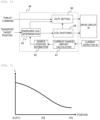
- FIG. 1 is a diagram showing the schematic configuration of the embodiment of the sample transport device according to the invention.
- a sample transport device 1 according to the invention includes: a magnetic body (permanent magnet) 10, a plurality of coils 25a and 25b that are provided to face the magnetic body 10; a coil drive unit 50 that applies a voltage to the coils 25a and 25b; and a calculation unit 40 including a position estimation unit that estimates a position of a permanent magnet 10.
- Current detectors 30a and 30b are provided between the coils 25a and 25b and the coil drive unit 50.
- the current detectors 30a and 30b, the calculation unit 40, and the coil drive unit 50 are connected to a power supply 55.
- the sample transport device will also be abbreviated as "the transport device”.
- the permanent magnet 10 is provided in a sample container (transport container) that accommodates a sample to be inspected.
- a transport surface is provided between the sample container where the permanent magnet 10 is provided and the coil 25.
- the coil 25 is configured with a core 22 that is formed of a magnetic body in a cylindrical shape and a winding wire 21 that is wound around an outer circumferential side of the core, and is disposed such that the permanent magnet 10 is positioned on the core 22.
- an electromagnetic force acts on the permanent magnet 10 such that the permanent magnet 10 can move to slide between the plurality of coils 25 through the transport surface.
- the sample container is transported up to a desired position.
- the force can be efficiently formed and the direction of the force can be controlled.
- a magnetic flux formed by the permanent magnet 10 acts on the coil 25a.
- the core 22 is formed of a magnetic body, and a magnetic flux passing through the core 22 has a characteristic in which the magnetic flux is less likely to pass through the core 22 as the size thereof increases.
- the inductance changes depending on magnetic saturation characteristic of the core 22.
- the inductance changes depending on the size of the magnetic flux generated in the core 22. That is, the inductance of the winding wire 21 changes depending on the size of the magnetic flux of the permanent magnet 10.
- the inductance of the winding wire 21 changes depending on the position of the permanent magnet 10 (that is, the sample container). Accordingly, as long as the inductance of the winding wire 21 can be measured, the position of the permanent magnet 10 on the transport surface can be detected.
- the summary of the position detection method based on the inductance characteristic of the coil is described.
- a voltage V generated in the winding wire 21 is represented by the following Expression (1).
- V ⁇ d ⁇ / dt
- ⁇ a magnetic flux
- t time
- the voltage V is represented by a change amount of the magnetic flux per unit time.
- the position of the permanent magnet 10 that is, the sample container can be obtained by applying a voltage signal for position detection and by detecting a change amount (dI/dt) of a current generated by the voltage application.
- dI/dt change amount
- the coil drive unit 50 is connected to the winding wires 21 of the coils 25a and 25b, and the current detectors 30a and 30b that detect currents flowing through the winding wires 21 are provided in the winding wires 21.
- the voltage is applied to the winding wire 21 by the coil drive unit 50, and the current flowing due to the voltage is detected by the current detector 30.
- the coil drive unit 50 corresponds to a bidirectional chopper or the like that is driven by a PWM (Pulse Width Modulation) signal.
- the current detector 30 that detects a current
- a device using a shunt resistor or a current transformer or a device using a Hall current sensor can be used as the current detector 30 that detects a current.
- the coil drive unit 50 is connected to the power supply 55, and a predetermined current flows through the winding wires 21 of the coils 25a and 25b by performing a duty control on the power supply voltage.
- the calculation unit 40 calculates a voltage command that is applied to the coil drive unit 50 to obtain a thrust required for transporting the sample container, measures the inductance (that is, the current change amount dI/dt) of the coil 25 based on the current value detected by the current detector 30, calculates a relative positional relationship between the coil 25 and the permanent magnet 10, and estimates the position of the permanent magnet 10 in the transport device 1. Using the calculated position information of the permanent magnet 10, the calculation unit 40 determines a timing at which a current required for transporting the permanent magnet 10 (sample container) is supplied from the coil drive unit 50 and appropriately supplies the current to the coils 25a and 25b.
- FIG. 2 is a functional block diagram showing processing contents of the calculation unit 40 in FIG. 1 .
- the calculation unit 40 inputs a thrust command determined depending on a target value of a transport speed of the sample container, determines a voltage pulse signal such as PWM in a duty setting unit 60, and outputs the voltage pulse signal to the coil drive unit 50.
- the current value is input from the current detector 30, the current change amount (dI/dt) of the coil is calculated by a current change amount calculation unit 61, and the position of the sample container is estimated based on the value in a sample position estimation unit 62. Further, the coil to be actually energized is determined in an energized coil determination unit 63 based on a transport target position of the sample and the above-described position of the sample container, and a circuit is switched based on the determined position in a coil switching unit 64 such that the desired coil can be energized.
- the control blocks described herein can be implemented by an arithmetic device such as a microcomputer.
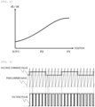
- FIG. 3 is a graph showing a positional characteristic of the inductance of the coil 25
- FIG. 4 is a graph showing a positional characteristic of the current change amount of the coil 25.
- P3 represents that the permanent magnet 10 is positioned immediately above the coil 25a
- P0 represents that the permanent magnet 10 is moved away from the coil 25a to be positioned above the coil 25b disposed adjacent to the coil 25a.
- the vertical axis L in FIG. 3 represents the inductance of the coil. It can be seen from this characteristic that, as the position changes from P3 to P0, the inductance increases. This characteristic is a change in an inductance caused due to the action of a magnetic flux generated by energizing the coil 25 and a magnetic flux generated by the permanent magnet 10.
- the position of the sample container is estimated using the positional characteristic of the inductance. Meanwhile, in the actual control logic, the current change amount of the coil is an input. Therefore, in the sample position estimation unit 62, the inductance L is set as a positional characteristic data table of the current change amount (dI/dt) shown in Fig. 4 . A relationship between the inductance L and the current change amount (dI/dt) is as described above in Expression (3).
- FIG. 5 is a graph showing an example of a waveform of a voltage pulse using a PWM conversion method.
- the voltage pulse shown in Fig. 5 is a voltage signal generated by the PWM conversion method, and the voltage pulse signal is generated by comparing a voltage command value and a PWM carrier.
- the PWM conversion converts the size of an amplitude into the width of a pulse.
- the voltage pulse shown in the lower portion of FIG. 5 includes information regarding the voltage command value shown in the upper portion of the drawing.
- the voltage command value described herein is obtained by adding a voltage for generating a thrust required for transporting the sample container and a voltage pulse for estimating the position of the sample container. When this voltage is applied to the coil 25, a current where an average current for generating a thrust and a current pulsation generated by the pulse are combined is generated.
- FIG. 5 shows the voltage output method in which a relatively high PWM period and a voltage pulse for position detection as a period lower than the PWM period are output using PWM conversion.
- FIG. 6 is a graph showing another example of the waveform of the voltage pulse using the PWM conversion method.
- the PWM period may be reduced to be the same as the period of the voltage pulse for position detection.
- FIG. 7 is a diagram showing an overall appearance of coils of the sample transport device according to the invention.
- Fig. 1 shows the cylindrical coil.
- the coil shape is not particularly limited to the cylindrical shape and may be a quadrangular prism shape as shown in Fig. 7 .
- Fig. 7 actually, a large number of coils are disposed in the sample transport device.
- the voltage pulse is applied to a coil near the transport path and the sample container among the coils such that the sample transport can be implemented while grasping the sample container position.
- an increase in the transport capacity of a sample is desired, and mass transport tends to be usual in the future.
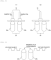
- FIG. 8 is a schematic diagram showing examples of a positional relationship between the coils constituting the sample transport device and a sample
- FIG. 9 is a conceptual diagram showing magnetic flux interference between adjacent coils.
- the coils 25a and 25b detect that the samples 70a and 70b are present immediately above the coils 25a and 25b, and are driven to transport the samples.
- the coils 25a and 25b apply voltage pulses for position detection to each other, and detect that the sample 70 is positioned between the coils.
- the coils 25a and 25b apply voltage pulses P1 and P2 to each other and are energized. Therefore, a change in magnetic flux corresponding to the voltage pulse occurs in each of the coils 25a and 25b.
- the voltage pulse for position detection is applied, and the position of a sample is detected based on the current change amount generated by the voltage pulse. Accordingly, when this magnetic interference disturbance occurs, the current change amounts in the adjacent coils 25a and 25b are changed.
- FIGS. 10 and 11 are graphs showing examples of the phase relationship of the voltage pulses for position detection between adjacent coils.
- FIGS. 10 and 11 are graphs showing examples of the phase relationship of the voltage pulses for position detection between adjacent coils.
- Fig. 10 when voltage pulses having the same phase are applied to adjacent coils, current pulsation occurs due to magnetic interference disturbance, and error may occur in the detection values of the current change amounts generated in the coils.
- error occurs in the estimated value of the sample position, the thrust characteristic deteriorates, and the sample transport capacity decreases.
- the invention when the voltage pulses for position detection are applied to adjacent coils to energize the coils, it is effective to shift the phases of the voltage pulses for position detection in the adjacent coils from each other as shown in Fig. 11 .
- the phases of the voltage pulses are shifted from each other as shown in Fig. 11 , the voltage of the pulses in one of the coils changes, and when the current change amount at the time is detected, the voltage pulse in the other coil is fixed without a change. Therefore, the influence of detection error on the current change amount during the above-described disturbance by magnetic interference is reduced.
- the influence of detection error is the minimum when the phase difference of the voltage pulses is 90 degrees as shown in Fig. 11 .
- the phase difference of the voltage pulses in the adjacent coils does not need to be strictly 90 degrees, and may be set such that the influence of magnetic flux interference on the other coil does not affect the transport performance of samples.
- a phase difference may be imparted to adjacent coils at the time when it is assumed from information regarding the transport path that the voltage pulses for position detection are subsequently applied to the coils.
- the influence of magnetic interference between a plurality of coils is suppressed when the coils are energized to transport a large number of samples, the position estimation accuracy of the sample carrier is ensured, and high-accuracy thrust control of the sample transport device can be implemented.
- a sample transport device capable of accurately detecting a position of a sample can be provided without providing a position sensor.
- the present invention is not limited to the embodiment and includes various modification examples.
- the embodiments have been described in order to easily understand the present invention, and the present invention is not necessarily to include all the configurations described above.
- a part of the configuration of one embodiment can also be replaced with the configuration of another embodiment.
- the configuration of one embodiment can be added to the configuration of another embodiment.
- addition, deletion, and replacement of another configuration can also be made for a part of the configuration in each of the embodiments.
Landscapes
- General Health & Medical Sciences (AREA)
- Health & Medical Sciences (AREA)
- Life Sciences & Earth Sciences (AREA)
- Chemical & Material Sciences (AREA)
- Analytical Chemistry (AREA)
- Biochemistry (AREA)
- Physics & Mathematics (AREA)
- General Physics & Mathematics (AREA)
- Immunology (AREA)
- Pathology (AREA)
- Non-Mechanical Conveyors (AREA)
- Automatic Analysis And Handling Materials Therefor (AREA)
- Measurement Of Length, Angles, Or The Like Using Electric Or Magnetic Means (AREA)
Abstract
Description
- The invention relates to a sample transport device.
- In sample processing devices for a clinical test, a sample such as blood, plasma, serum, urine, or body fluid is evaluated for instructed analysis items. As the sample processing devices, a plurality of devices having respective functions of inspecting the analysis items are connected such that the respective steps can be automatically processed. That is, in order to rationalize operations in a laboratory, analysis units in a plurality of fields of analysis such as biochemistry or immunity are connected through a transport line and operate as one device. In the related art, a belt driving type transport line is mainly used, and when the transport is stopped due to some kind of abnormality during the transport, a sample cannot be supplied to devices provided downstream of the stop position. In addition, the importance of the sample processing has increased due to the advancement of medical care and the development of an aging society. Therefore, in order to improve the processing capacity of the sample processing device, high-speed transport or simultaneous mass transport of samples and the development of a device capable of transport in a plurality of directions are desired.
- In order to achieve this object,
JP-A-2017-77971 - In addition,
JP-A-2017-102103 - In the transport method and the system, a container carrier detection device is provided to detect the position of the magnetically active device provided in the sample transport carrier. In
PTL 1, a sample carrier detection device is provided to detect the presence and the position of the container carrier positioned on the transport plane. In addition, inPTL 2, the laboratory sample distribution system includes the transport plane, and a plurality of electromagnetic actuators are disposed below the transport plane. A plurality of position sensors are distributed on the transport plane.PTL 2 describes that Hall sensors are used as the position sensors. -
- PTL 1:
JP-A-2017-77971 - PTL 2:
JP-A-2017-102103 - In the systems disclosed in
PTL 1 andPTL 2, a plurality of container carrier detection devices, that is, position sensors are required to transport a large number of samples with high speed, and a decrease in reliability caused by high cost or a malfunction of the detection devices is concerned. Further, when the position sensors are used inPTL 1 andPTL 2, whether or not a sample is present cannot be detected unless the sample approaches the position sensors to some degree. Therefore, a problem may also occur in that the position detection accuracy of the sample is limited. - The invention has been made in order to solve the above-described problems, and an object thereof is to provide a sample transport device capable of accurately detecting a position of a sample without providing a position sensor.
- In order to achieve the above-described object, according to the invention, there is provided a sample transport device including: a sample container configured to accommodate a sample and provided with a magnetic body; a transport surface on which the sample container is to be transported; a plurality of coils disposed on a surface of the transport surface that is opposite to a surface facing the magnetic body; a coil drive unit configured to apply a voltage to the coils; and a position estimation unit configured to estimate a position of the sample container based on a current change generated when the coil drive unit applies the voltage to the coils, in which the position estimation unit is configured to estimate the position of the transport container by the coil drive unit applying voltage pulses having a phase difference to adjacent coils among the plurality of coils.
- A more specific configuration of the invention is described in the claims.
- According to the invention, a sample transport device capable of accurately detecting a position of a sample can be provided without providing a position sensor.
- Objects, configurations, and effects other than those described above will be clarified by describing the following embodiments.
-
- [
FIG. 1] FIG. 1 is a diagram showing a schematic configuration of an embodiment of a sample transport device according to the invention. - [
FIG. 2] FIG. 2 is a functional block diagram showing processing contents of acalculation unit 40 inFIG. 1 . - [
FIG. 3] FIG. 3 is a graph showing a positional characteristic of an inductance of acoil 25. - [
FIG. 4] FIG. 4 is a graph showing a positional characteristic of a current change amount of thecoil 25. - [
FIG. 5] FIG. 5 is a graph showing an example of a waveform of a voltage pulse using a PWM conversion method. - [
FIG. 6] FIG. 6 is a graph showing another example of the waveform of the voltage pulse using the PWM conversion method. - [
FIG. 7] FIG. 7 is a diagram showing an overall appearance of coils of the sample transport device according to the invention. - [
FIG. 8] FIG. 8 is a schematic diagram showing examples of a positional relationship between the coils constituting the sample transport device and a sample. - [
FIG. 9] FIG. 9 is a conceptual diagram showing magnetic flux interference between adjacent coils. - [
FIG. 10] FIG. 10 is a graph showing an example of a phase relationship of voltage pulses for position detection between adjacent coils. - [
FIG. 11] FIG. 11 is a graph showing an example of the phase relationship of the voltage pulses for position detection between adjacent coils. - Hereinafter, an embodiment of the invention will be described in detail. First, a schematic configuration of a sample transport device according to the invention will be described using
FIG. 1. FIG. 1 is a diagram showing the schematic configuration of the embodiment of the sample transport device according to the invention. As shown inFIG. 1 , asample transport device 1 according to the invention includes: a magnetic body (permanent magnet) 10, a plurality ofcoils magnetic body 10; acoil drive unit 50 that applies a voltage to thecoils calculation unit 40 including a position estimation unit that estimates a position of apermanent magnet 10.Current detectors coils coil drive unit 50. Thecurrent detectors calculation unit 40, and thecoil drive unit 50 are connected to apower supply 55. Hereinafter, "the sample transport device" will also be abbreviated as "the transport device". - Although not shown in
FIG. 1 , thepermanent magnet 10 is provided in a sample container (transport container) that accommodates a sample to be inspected. In addition, a transport surface is provided between the sample container where thepermanent magnet 10 is provided and thecoil 25. Thecoil 25 is configured with acore 22 that is formed of a magnetic body in a cylindrical shape and awinding wire 21 that is wound around an outer circumferential side of the core, and is disposed such that thepermanent magnet 10 is positioned on thecore 22. By causing a current to flow through the windingwire 21, an electromagnetic force acts on thepermanent magnet 10 such that thepermanent magnet 10 can move to slide between the plurality ofcoils 25 through the transport surface. As a result, the sample container is transported up to a desired position. - During this electromagnetic transport, in order to make an electromagnetic force to efficiently act on the
permanent magnet 10 and to move the sample container in a desired direction, relative position information regarding thepermanent magnet 10 and thecoils FIG. 1 , thepermanent magnet 10 is positioned immediately above thecoil 25a among the two coils. In this case, however, even when a current flows through thecoil 25a, a force in the horizontal direction, that is, in the transport direction is not generated. Conversely, by causing a current to flow through the coil (coil that is not positioned immediately above the permanent magnet 10) 25b adjacent to thecoil 25a, a force to attract thepermanent magnet 10 to thecoil 25b can be generated, and thepermanent magnet 10 can be transported in the transport direction (arrow direction inFIG. 1 ). - That is, when the position of the
permanent magnet 10 is grasped and a force (attractive force) to attract thepermanent magnet 10 to thecoil 25b in the transport direction is generated, the force can be efficiently formed and the direction of the force can be controlled. - It can be seen from the above description that, in order to control an
electromagnetic transport device 1, the position of thepermanent magnet 10 on the transport surface needs to be detected. Due to the necessity of the position information, as in the related art, a large number of position sensors are disposed on the transport surface to detect the position of the sample container. - Here, as described above, when many position sensors are used, accurate position information can be obtained. However, it is considered that a new substrate on which the position sensors are mounted is required, which brings about an increase in cost or an increase in device size. Accordingly, it is desired to detect the position of the sample container without using the position sensors. As a method for the detection, a method of measuring the inductance of the coil that changes depending on the position of the
permanent magnet 10 attached to the sample container is considered. Hereinafter, the position detection method based on the inductance characteristic of the coil will be described. - First, when the
permanent magnet 10 is present on thecoil 25a on the proximal side ofFIG. 1 , a magnetic flux formed by thepermanent magnet 10 acts on thecoil 25a. Here, there is a difference in the size of the magnetic flux to act between thecoil 25a close to thepermanent magnet 10 and thecoil 25b far from thepermanent magnet 10. That is, the size of the magnetic flux to act on the coil side changes depending on the relative position between thepermanent magnet 10 and the coil. In addition, thecore 22 is formed of a magnetic body, and a magnetic flux passing through thecore 22 has a characteristic in which the magnetic flux is less likely to pass through the core 22 as the size thereof increases. Here, when a voltage is applied to the windingwire 21 by thecoil drive unit 50 such that a current flows therethrough, a magnetic flux is generated by the current in thecore 22. Accordingly, a magnetic flux generated by thepermanent magnet 10 and a magnetic flux generated by the current flowing through the windingwire 21 are present in thecore 22. - In general, when a current flows through the winding
wire 21, a magnetic field is generated around the windingwire 21, and the generated magnetic flux is proportional to the current value flowing therethrough. This constant proportionality is called an inductance. However, in a circuit including a magnetic body such as thecore 22, the inductance changes depending on magnetic saturation characteristic of thecore 22. When magnetic saturation occurs in thecore 22, the inductance changes depending on the size of the magnetic flux generated in thecore 22. That is, the inductance of the windingwire 21 changes depending on the size of the magnetic flux of thepermanent magnet 10. This implies that the inductance of the windingwire 21 changes depending on the position of the permanent magnet 10 (that is, the sample container). Accordingly, as long as the inductance of the windingwire 21 can be measured, the position of thepermanent magnet 10 on the transport surface can be detected. Hereinabove, the summary of the position detection method based on the inductance characteristic of the coil is described. - Accordingly, the more specific principle of the position detection method will be described. First, a voltage V generated in the winding
wire 21 is represented by the following Expression (1).
- In addition, assuming that I represents a current and L represents an inductance, a relationship of the following Expression (2) is satisfied.


- That is, when a given voltage is applied to the winding
wire 21, as shown in Expression (3), a time change amount of the current I supplied changes depending on the size of the inductance L. This implies that the rise of the current supplied varies when the voltage is applied. Accordingly, when the voltage is applied to the windingwire 21, the inductance L can be obtained by calculation by detecting the change amount (dI/dt) of the current generated in the windingwire 21. That is, as long as the inductance characteristic of the windingwire 21 that changes depending on the position of thepermanent magnet 10 can be grasped in advance, the position of thepermanent magnet 10, that is, the sample container can be obtained by applying a voltage signal for position detection and by detecting a change amount (dI/dt) of a current generated by the voltage application. With this configuration, the position of the sample container can be grasped without providing a position sensor. - Next, a circuit configuration that implements the method in which a position sensor is not provided will be described. First, as shown in
FIG. 1 , thecoil drive unit 50 is connected to the windingwires 21 of thecoils current detectors wires 21 are provided in the windingwires 21. In this embodiment, the voltage is applied to the windingwire 21 by thecoil drive unit 50, and the current flowing due to the voltage is detected by thecurrent detector 30. Here, thecoil drive unit 50 corresponds to a bidirectional chopper or the like that is driven by a PWM (Pulse Width Modulation) signal. In addition, as thecurrent detector 30 that detects a current, a device using a shunt resistor or a current transformer or a device using a Hall current sensor can be used. However, the embodiment is not particularly limited to these devices. Thecoil drive unit 50 is connected to thepower supply 55, and a predetermined current flows through the windingwires 21 of thecoils - The
calculation unit 40 calculates a voltage command that is applied to thecoil drive unit 50 to obtain a thrust required for transporting the sample container, measures the inductance (that is, the current change amount dI/dt) of thecoil 25 based on the current value detected by thecurrent detector 30, calculates a relative positional relationship between thecoil 25 and thepermanent magnet 10, and estimates the position of thepermanent magnet 10 in thetransport device 1. Using the calculated position information of thepermanent magnet 10, thecalculation unit 40 determines a timing at which a current required for transporting the permanent magnet 10 (sample container) is supplied from thecoil drive unit 50 and appropriately supplies the current to thecoils - An example of this sample transport control at the time is shown in a block diagram of
FIG. 2. FIG. 2 is a functional block diagram showing processing contents of thecalculation unit 40 inFIG. 1 . As shown inFIG. 2 , thecalculation unit 40 inputs a thrust command determined depending on a target value of a transport speed of the sample container, determines a voltage pulse signal such as PWM in aduty setting unit 60, and outputs the voltage pulse signal to thecoil drive unit 50. At this time, in order to determine which one of thecoils current detector 30, the current change amount (dI/dt) of the coil is calculated by a current changeamount calculation unit 61, and the position of the sample container is estimated based on the value in a sampleposition estimation unit 62. Further, the coil to be actually energized is determined in an energizedcoil determination unit 63 based on a transport target position of the sample and the above-described position of the sample container, and a circuit is switched based on the determined position in acoil switching unit 64 such that the desired coil can be energized. The control blocks described herein can be implemented by an arithmetic device such as a microcomputer. - The sample
position estimation unit 62 shown inFig. 2 will be described in detail. In the sampleposition estimation unit 62, as described above, the current change amount (dI/dt, that is, corresponding to the inductance L of thecoils FIG. 3 is a graph showing a positional characteristic of the inductance of thecoil 25, andFIG. 4 is a graph showing a positional characteristic of the current change amount of thecoil 25. InFIG. 3 , P3 represents that thepermanent magnet 10 is positioned immediately above thecoil 25a, and P0 represents that thepermanent magnet 10 is moved away from thecoil 25a to be positioned above thecoil 25b disposed adjacent to thecoil 25a. Further, the vertical axis L inFIG. 3 represents the inductance of the coil. It can be seen from this characteristic that, as the position changes from P3 to P0, the inductance increases. This characteristic is a change in an inductance caused due to the action of a magnetic flux generated by energizing thecoil 25 and a magnetic flux generated by thepermanent magnet 10. In the embodiment, in principle, the position of the sample container is estimated using the positional characteristic of the inductance. Meanwhile, in the actual control logic, the current change amount of the coil is an input. Therefore, in the sampleposition estimation unit 62, the inductance L is set as a positional characteristic data table of the current change amount (dI/dt) shown inFig. 4 . A relationship between the inductance L and the current change amount (dI/dt) is as described above in Expression (3). - Next, a method of applying a voltage required for detecting the sample container position will be described.
FIG. 5 is a graph showing an example of a waveform of a voltage pulse using a PWM conversion method. The voltage pulse shown inFig. 5 is a voltage signal generated by the PWM conversion method, and the voltage pulse signal is generated by comparing a voltage command value and a PWM carrier. In general, the PWM conversion converts the size of an amplitude into the width of a pulse. Accordingly, the voltage pulse shown in the lower portion ofFIG. 5 includes information regarding the voltage command value shown in the upper portion of the drawing. The voltage command value described herein is obtained by adding a voltage for generating a thrust required for transporting the sample container and a voltage pulse for estimating the position of the sample container. When this voltage is applied to thecoil 25, a current where an average current for generating a thrust and a current pulsation generated by the pulse are combined is generated. -
FIG. 5 shows the voltage output method in which a relatively high PWM period and a voltage pulse for position detection as a period lower than the PWM period are output using PWM conversion. However, as long as the sample container can be transported and the current change amount during the transport can be measured, the embodiment is not limited to this method.FIG. 6 is a graph showing another example of the waveform of the voltage pulse using the PWM conversion method. For example, as shown inFig. 6 , the PWM period may be reduced to be the same as the period of the voltage pulse for position detection. -
FIG. 7 is a diagram showing an overall appearance of coils of the sample transport device according to the invention.Fig. 1 shows the cylindrical coil. However, the coil shape is not particularly limited to the cylindrical shape and may be a quadrangular prism shape as shown inFig. 7 . As shown inFig. 7 , actually, a large number of coils are disposed in the sample transport device. Depending on a transport path of a sample, the voltage pulse is applied to a coil near the transport path and the sample container among the coils such that the sample transport can be implemented while grasping the sample container position. In the electromagnetic transport device according to the present invention shown inFig. 7 , an increase in the transport capacity of a sample is desired, and mass transport tends to be usual in the future. This way, as the number of samples transported increases, the number of thecoils 25 in the sample transport device increases, the interval distance between the plurality of coils decreases, the distance between the samples to be transported decreases, and the possibility that adjacent coils are energized at the same time increases. - Accordingly, the invention is configured such that magnetic flux interference does not occur between adjacent coils.
FIG. 8 is a schematic diagram showing examples of a positional relationship between the coils constituting the sample transport device and a sample, andFIG. 9 is a conceptual diagram showing magnetic flux interference between adjacent coils. InFIG. 8(1) , whensamples adjacent coils coils samples coils Fig. 8(2) , when thesample 70 is present between the twoadjacent coils coils sample 70 is positioned between the coils. - In this case, as shown in
Fig. 9 , thecoils coils - As described above, when the interval between adjacent coils is small, changes in magnetic flux occur in the respective coils, and induced voltages interfere with each other to cause disturbance. In the method according to the invention in which a position sensor is not provided, the voltage pulse for position detection is applied, and the position of a sample is detected based on the current change amount generated by the voltage pulse. Accordingly, when this magnetic interference disturbance occurs, the current change amounts in the
adjacent coils -
FIGS. 10 and 11 are graphs showing examples of the phase relationship of the voltage pulses for position detection between adjacent coils. For example, as shown inFig. 10 , when voltage pulses having the same phase are applied to adjacent coils, current pulsation occurs due to magnetic interference disturbance, and error may occur in the detection values of the current change amounts generated in the coils. As a result, there is a possibility that error occurs in the estimated value of the sample position, the thrust characteristic deteriorates, and the sample transport capacity decreases. - Accordingly, in order to solve the above-described problem, in the invention, when the voltage pulses for position detection are applied to adjacent coils to energize the coils, it is effective to shift the phases of the voltage pulses for position detection in the adjacent coils from each other as shown in
Fig. 11 . When the phases of the voltage pulses are shifted from each other as shown inFig. 11 , the voltage of the pulses in one of the coils changes, and when the current change amount at the time is detected, the voltage pulse in the other coil is fixed without a change. Therefore, the influence of detection error on the current change amount during the above-described disturbance by magnetic interference is reduced. The influence of detection error is the minimum when the phase difference of the voltage pulses is 90 degrees as shown inFig. 11 . At this time, the phase difference of the voltage pulses in the adjacent coils does not need to be strictly 90 degrees, and may be set such that the influence of magnetic flux interference on the other coil does not affect the transport performance of samples. - As described above, when the amount of samples transported by the
transport device 1 increases in the future, it is considered that a large number of samples are transported, and it is difficult to impart a phase difference at all times such that magnetic flux interference does not occur (affect) between the samples. In this case, in the energizedcoil determination unit 63 inFig. 2 , a phase difference may be imparted to adjacent coils at the time when it is assumed from information regarding the transport path that the voltage pulses for position detection are subsequently applied to the coils. - With the above-described configuration, the influence of magnetic interference between a plurality of coils is suppressed when the coils are energized to transport a large number of samples, the position estimation accuracy of the sample carrier is ensured, and high-accuracy thrust control of the sample transport device can be implemented.
- As described above, according to the invention, a sample transport device capable of accurately detecting a position of a sample can be provided without providing a position sensor.
- The present invention is not limited to the embodiment and includes various modification examples.
For example, the embodiments have been described in order to easily understand the present invention, and the present invention is not necessarily to include all the configurations described above. In addition, a part of the configuration of one embodiment can also be replaced with the configuration of another embodiment. Further, the configuration of one embodiment can be added to the configuration of another embodiment. Further, addition, deletion, and replacement of another configuration can also be made for a part of the configuration in each of the embodiments. -
- 1 transport device
- 10 permanent magnet
- 21 winding wire
- 22 core
- 25a, 25b coil
- 30a, 30b current detector
- 40 calculation unit
- 50 coil drive unit
- 55 power supply
- 60 duty setting unit
- 61 current change amount calculation unit
- 62 sample position estimation unit
- 63 energized coil determination unit
- 64 coil switching unit
- 70a, 70b sample
Claims (3)
- A sample transport device comprising:a sample container configured to accommodate a sample and provided with a magnetic body;a transport surface on which the sample container is to be transported;a plurality of coils disposed on a surface of the transport surface that is opposite to a surface facing the magnetic body;a coil drive unit configured to apply a voltage to the coils; anda position estimation unit configured to estimate a position of the sample container based on a current change generated when the coil drive unit applies the voltage to the coils, whereinthe position estimation unit is configured to estimate the position of the sample container by the coil drive unit applying voltage pulses having a phase difference to adjacent coils among the plurality of coils.
- The sample transport device according to claim 1, wherein
the phase difference is 90 degrees. - The sample transport device according to claim 1 or 2, wherein
the position estimation unit imparts the phase difference between pulse voltages applied to the adjacent coils at a time when it is assumed that the voltage pulses are simultaneously applied to the adjacent coils in a transport path ahead of the sample container.
Applications Claiming Priority (2)
| Application Number | Priority Date | Filing Date | Title |
|---|---|---|---|
| JP2020100731A JP7465727B2 (en) | 2020-06-10 | 2020-06-10 | Sample transport device |
| PCT/JP2021/012505 WO2021250978A1 (en) | 2020-06-10 | 2021-03-25 | Specimen carrying device |
Publications (2)
| Publication Number | Publication Date |
|---|---|
| EP4166486A1 true EP4166486A1 (en) | 2023-04-19 |
| EP4166486A4 EP4166486A4 (en) | 2024-05-15 |
Family
ID=78845588
Family Applications (1)
| Application Number | Title | Priority Date | Filing Date |
|---|---|---|---|
| EP21821981.4A Pending EP4166486A4 (en) | 2020-06-10 | 2021-03-25 | SAMPLE TRANSPORT DEVICE |
Country Status (5)
| Country | Link |
|---|---|
| US (1) | US20230184798A1 (en) |
| EP (1) | EP4166486A4 (en) |
| JP (1) | JP7465727B2 (en) |
| CN (1) | CN115698727A (en) |
| WO (1) | WO2021250978A1 (en) |
Families Citing this family (3)
| Publication number | Priority date | Publication date | Assignee | Title |
|---|---|---|---|---|
| JP7766454B2 (en) * | 2021-10-13 | 2025-11-10 | 株式会社日立ハイテク | Conveyor |
| JP7735528B2 (en) * | 2022-02-25 | 2025-09-08 | 株式会社日立ハイテク | Conveying device and conveying method |
| EP4685091A1 (en) | 2023-03-06 | 2026-01-28 | Hitachi High-Tech Corporation | Conveyance device and conveyance method |
Family Cites Families (18)
| Publication number | Priority date | Publication date | Assignee | Title |
|---|---|---|---|---|
| JPS62114402A (en) * | 1985-11-11 | 1987-05-26 | Shinko Electric Co Ltd | Linear motor type conveyor |
| JPH05153704A (en) * | 1991-11-26 | 1993-06-18 | Hitachi Ltd | Method and apparatus for controlling planar magnetic repellent/attractive levitation control |
| JP3219441B2 (en) * | 1991-12-20 | 2001-10-15 | 三菱重工業株式会社 | Magnetic levitation transfer device |
| JPH05199616A (en) * | 1992-01-17 | 1993-08-06 | Fujitsu Ltd | Conveyor control device |
| JP3047099B2 (en) * | 1997-01-20 | 2000-05-29 | 株式会社マコメ研究所 | Position detection device |
| US8499697B2 (en) | 2009-02-20 | 2013-08-06 | General Atomics | System and method for vehicle position sensing with use of propulsion windings |
| EP2589967A1 (en) * | 2011-11-04 | 2013-05-08 | Roche Diagnostics GmbH | Laboratory sample distribution system and corresponding method of operation |
| WO2013116651A1 (en) * | 2012-02-03 | 2013-08-08 | Siemens Healthcare Diagnostics Inc. | Power source for an automation system mechanism |
| EP2977766A1 (en) | 2014-07-24 | 2016-01-27 | Roche Diagniostics GmbH | Laboratory sample distribution system and laboratory automation system |
| EP2995958A1 (en) * | 2014-09-15 | 2016-03-16 | Roche Diagniostics GmbH | Method of operating a laboratory sample distribution system, laboratory sample distribution system and laboratory automation system |
| CN107614314B (en) * | 2015-05-29 | 2020-08-04 | 株式会社安川电机 | Conveying system and conveying equipment construction method |
| EP3156352B1 (en) | 2015-10-13 | 2019-02-27 | Roche Diagniostics GmbH | Laboratory sample distribution system and laboratory automation system |
| EP3383547A4 (en) * | 2015-11-30 | 2019-08-07 | DH Technologies Development PTE. Ltd. | ELECTROMAGNETIC ASSEMBLIES FOR THE TREATMENT OF FLUIDS |
| EP3355065B1 (en) * | 2017-01-31 | 2021-08-18 | Roche Diagnostics GmbH | Laboratory sample distribution system and laboratory automation system |
| WO2019082750A1 (en) | 2017-10-24 | 2019-05-02 | パナソニックIpマネジメント株式会社 | Planar motor system, control device, and movement method |
| JP7025256B2 (en) * | 2018-03-16 | 2022-02-24 | キヤノン株式会社 | Manufacturing methods for stage equipment, lithography equipment, and articles |
| US10457497B1 (en) * | 2018-04-13 | 2019-10-29 | Laitram, L.L.C. | Electromagnetic conveyor system |
| WO2019225284A1 (en) | 2018-05-25 | 2019-11-28 | パナソニックIpマネジメント株式会社 | Planar motor and control method |
-
2020
- 2020-06-10 JP JP2020100731A patent/JP7465727B2/en active Active
-
2021
- 2021-03-25 WO PCT/JP2021/012505 patent/WO2021250978A1/en not_active Ceased
- 2021-03-25 US US17/923,616 patent/US20230184798A1/en active Pending
- 2021-03-25 CN CN202180040249.3A patent/CN115698727A/en active Pending
- 2021-03-25 EP EP21821981.4A patent/EP4166486A4/en active Pending
Also Published As
| Publication number | Publication date |
|---|---|
| WO2021250978A1 (en) | 2021-12-16 |
| CN115698727A (en) | 2023-02-03 |
| JP2021196193A (en) | 2021-12-27 |
| EP4166486A4 (en) | 2024-05-15 |
| JP7465727B2 (en) | 2024-04-11 |
| US20230184798A1 (en) | 2023-06-15 |
Similar Documents
| Publication | Publication Date | Title |
|---|---|---|
| JP7304219B2 (en) | Conveyor | |
| US20230184798A1 (en) | Sample transport device | |
| JP7107866B2 (en) | Conveying device and conveying method of conveyed object | |
| US20210398723A1 (en) | Conveyance Apparatus, Sample Analysis System Including the Same, and Sample Preprocessing Apparatus | |
| JP2018136313A (en) | Laboratory sample distribution system and laboratory automation system | |
| WO2021065362A1 (en) | Conveyor device and analysis system | |
| US20230211964A1 (en) | Transport Device and Analysis System | |
| JP7708646B2 (en) | Conveyor | |
| US20250070694A1 (en) | Conveying device and conveying method | |
| EP4418528A1 (en) | Transport device | |
| CN116568617B (en) | Sample conveying device | |
| US20250145393A1 (en) | Conveying device and conveying method | |
| EP4101794A1 (en) | Specimen transport system and specimen transport method | |
| WO2025258557A1 (en) | Electromagnetic-type specimen conveyance device | |
| US20230184799A1 (en) | Transport Device and Analysis System |
Legal Events
| Date | Code | Title | Description |
|---|---|---|---|
| STAA | Information on the status of an ep patent application or granted ep patent |
Free format text: STATUS: THE INTERNATIONAL PUBLICATION HAS BEEN MADE |
|
| PUAI | Public reference made under article 153(3) epc to a published international application that has entered the european phase |
Free format text: ORIGINAL CODE: 0009012 |
|
| STAA | Information on the status of an ep patent application or granted ep patent |
Free format text: STATUS: REQUEST FOR EXAMINATION WAS MADE |
|
| 17P | Request for examination filed |
Effective date: 20221118 |
|
| AK | Designated contracting states |
Kind code of ref document: A1 Designated state(s): AL AT BE BG CH CY CZ DE DK EE ES FI FR GB GR HR HU IE IS IT LI LT LU LV MC MK MT NL NO PL PT RO RS SE SI SK SM TR |
|
| DAV | Request for validation of the european patent (deleted) | ||
| DAX | Request for extension of the european patent (deleted) | ||
| A4 | Supplementary search report drawn up and despatched |
Effective date: 20240416 |
|
| RIC1 | Information provided on ipc code assigned before grant |
Ipc: G01N 35/04 20060101ALI20240410BHEP Ipc: B65G 54/02 20060101AFI20240410BHEP |
|
| STAA | Information on the status of an ep patent application or granted ep patent |
Free format text: STATUS: EXAMINATION IS IN PROGRESS |
|
| 17Q | First examination report despatched |
Effective date: 20250219 |