EP4166416A1 - Obstacle detection system, obstacle detection method, and self-location estimation system - Google Patents
Obstacle detection system, obstacle detection method, and self-location estimation system Download PDFInfo
- Publication number
- EP4166416A1 EP4166416A1 EP21822778.3A EP21822778A EP4166416A1 EP 4166416 A1 EP4166416 A1 EP 4166416A1 EP 21822778 A EP21822778 A EP 21822778A EP 4166416 A1 EP4166416 A1 EP 4166416A1
- Authority
- EP
- European Patent Office
- Prior art keywords
- obstacle
- detection
- train
- sensor
- monitoring area
- Prior art date
- Legal status (The legal status is an assumption and is not a legal conclusion. Google has not performed a legal analysis and makes no representation as to the accuracy of the status listed.)
- Pending
Links
Images













Classifications
-
- B—PERFORMING OPERATIONS; TRANSPORTING
- B61—RAILWAYS
- B61L—GUIDING RAILWAY TRAFFIC; ENSURING THE SAFETY OF RAILWAY TRAFFIC
- B61L23/00—Control, warning or like safety means along the route or between vehicles or trains
- B61L23/04—Control, warning or like safety means along the route or between vehicles or trains for monitoring the mechanical state of the route
- B61L23/041—Obstacle detection
-
- B—PERFORMING OPERATIONS; TRANSPORTING
- B61—RAILWAYS
- B61L—GUIDING RAILWAY TRAFFIC; ENSURING THE SAFETY OF RAILWAY TRAFFIC
- B61L15/00—Indicators provided on the vehicle or train for signalling purposes
- B61L15/0072—On-board train data handling
-
- B—PERFORMING OPERATIONS; TRANSPORTING
- B61—RAILWAYS
- B61L—GUIDING RAILWAY TRAFFIC; ENSURING THE SAFETY OF RAILWAY TRAFFIC
- B61L25/00—Recording or indicating positions or identities of vehicles or trains or setting of track apparatus
- B61L25/02—Indicating or recording positions or identities of vehicles or trains
- B61L25/025—Absolute localisation, e.g. providing geodetic coordinates
-
- G—PHYSICS
- G01—MEASURING; TESTING
- G01S—RADIO DIRECTION-FINDING; RADIO NAVIGATION; DETERMINING DISTANCE OR VELOCITY BY USE OF RADIO WAVES; LOCATING OR PRESENCE-DETECTING BY USE OF THE REFLECTION OR RERADIATION OF RADIO WAVES; ANALOGOUS ARRANGEMENTS USING OTHER WAVES
- G01S17/00—Systems using the reflection or reradiation of electromagnetic waves other than radio waves, e.g. lidar systems
- G01S17/02—Systems using the reflection of electromagnetic waves other than radio waves
- G01S17/06—Systems determining position data of a target
- G01S17/42—Simultaneous measurement of distance and other co-ordinates
-
- G—PHYSICS
- G01—MEASURING; TESTING
- G01S—RADIO DIRECTION-FINDING; RADIO NAVIGATION; DETERMINING DISTANCE OR VELOCITY BY USE OF RADIO WAVES; LOCATING OR PRESENCE-DETECTING BY USE OF THE REFLECTION OR RERADIATION OF RADIO WAVES; ANALOGOUS ARRANGEMENTS USING OTHER WAVES
- G01S17/00—Systems using the reflection or reradiation of electromagnetic waves other than radio waves, e.g. lidar systems
- G01S17/88—Lidar systems specially adapted for specific applications
- G01S17/93—Lidar systems specially adapted for specific applications for anti-collision purposes
- G01S17/931—Lidar systems specially adapted for specific applications for anti-collision purposes of land vehicles
-
- G—PHYSICS
- G01—MEASURING; TESTING
- G01S—RADIO DIRECTION-FINDING; RADIO NAVIGATION; DETERMINING DISTANCE OR VELOCITY BY USE OF RADIO WAVES; LOCATING OR PRESENCE-DETECTING BY USE OF THE REFLECTION OR RERADIATION OF RADIO WAVES; ANALOGOUS ARRANGEMENTS USING OTHER WAVES
- G01S5/00—Position-fixing by co-ordinating two or more direction or position line determinations; Position-fixing by co-ordinating two or more distance determinations
-
- G—PHYSICS
- G06—COMPUTING OR CALCULATING; COUNTING
- G06V—IMAGE OR VIDEO RECOGNITION OR UNDERSTANDING
- G06V20/00—Scenes; Scene-specific elements
- G06V20/50—Context or environment of the image
- G06V20/56—Context or environment of the image exterior to a vehicle by using sensors mounted on the vehicle
- G06V20/58—Recognition of moving objects or obstacles, e.g. vehicles or pedestrians; Recognition of traffic objects, e.g. traffic signs, traffic lights or roads
-
- G—PHYSICS
- G01—MEASURING; TESTING
- G01S—RADIO DIRECTION-FINDING; RADIO NAVIGATION; DETERMINING DISTANCE OR VELOCITY BY USE OF RADIO WAVES; LOCATING OR PRESENCE-DETECTING BY USE OF THE REFLECTION OR RERADIATION OF RADIO WAVES; ANALOGOUS ARRANGEMENTS USING OTHER WAVES
- G01S13/00—Systems using the reflection or reradiation of radio waves, e.g. radar systems; Analogous systems using reflection or reradiation of waves whose nature or wavelength is irrelevant or unspecified
- G01S13/87—Combinations of radar systems, e.g. primary radar and secondary radar
- G01S13/876—Combination of several spaced transponders or reflectors of known location for determining the position of a receiver
-
- G—PHYSICS
- G01—MEASURING; TESTING
- G01S—RADIO DIRECTION-FINDING; RADIO NAVIGATION; DETERMINING DISTANCE OR VELOCITY BY USE OF RADIO WAVES; LOCATING OR PRESENCE-DETECTING BY USE OF THE REFLECTION OR RERADIATION OF RADIO WAVES; ANALOGOUS ARRANGEMENTS USING OTHER WAVES
- G01S17/00—Systems using the reflection or reradiation of electromagnetic waves other than radio waves, e.g. lidar systems
- G01S17/87—Combinations of systems using electromagnetic waves other than radio waves
-
- G—PHYSICS
- G01—MEASURING; TESTING
- G01S—RADIO DIRECTION-FINDING; RADIO NAVIGATION; DETERMINING DISTANCE OR VELOCITY BY USE OF RADIO WAVES; LOCATING OR PRESENCE-DETECTING BY USE OF THE REFLECTION OR RERADIATION OF RADIO WAVES; ANALOGOUS ARRANGEMENTS USING OTHER WAVES
- G01S13/00—Systems using the reflection or reradiation of radio waves, e.g. radar systems; Analogous systems using reflection or reradiation of waves whose nature or wavelength is irrelevant or unspecified
- G01S13/88—Radar or analogous systems specially adapted for specific applications
- G01S13/93—Radar or analogous systems specially adapted for specific applications for anti-collision purposes
- G01S13/931—Radar or analogous systems specially adapted for specific applications for anti-collision purposes of land vehicles
- G01S2013/9327—Sensor installation details
- G01S2013/93271—Sensor installation details in the front of the vehicles
-
- G—PHYSICS
- G01—MEASURING; TESTING
- G01S—RADIO DIRECTION-FINDING; RADIO NAVIGATION; DETERMINING DISTANCE OR VELOCITY BY USE OF RADIO WAVES; LOCATING OR PRESENCE-DETECTING BY USE OF THE REFLECTION OR RERADIATION OF RADIO WAVES; ANALOGOUS ARRANGEMENTS USING OTHER WAVES
- G01S13/00—Systems using the reflection or reradiation of radio waves, e.g. radar systems; Analogous systems using reflection or reradiation of waves whose nature or wavelength is irrelevant or unspecified
- G01S13/88—Radar or analogous systems specially adapted for specific applications
- G01S13/93—Radar or analogous systems specially adapted for specific applications for anti-collision purposes
- G01S13/931—Radar or analogous systems specially adapted for specific applications for anti-collision purposes of land vehicles
- G01S2013/9328—Rail vehicles
Definitions
- the present invention relates to an obstacle detection system and an obstacle detection method for detecting an obstacle while traveling on a trajectory, and a self-position estimation system that estimates a self-position while traveling on a trajectory.
- an obstacle detection system that automatically stops an inspection vehicle that travels before a business vehicle starts traveling when there is an obstacle within a construction limit (in order to secure the safety of a train operation, a prescribed range in which buildings or the like that may be obstacles must not be installed) when whether or not a rail has an abnormality is checked by automatic traveling.
- a technique of detecting an obstacle from a short distance image capturing unit that is provided in a vehicle and captures an image at a short distance while causing the vehicle to be self-propelled a long distance image capturing unit that captures an image at a long distance, and a LIDAR that further irradiates the inside of the short distance.
- PTL 1 discloses a technique of setting a determination line at a plurality of distances in front of a vehicle and determining an object as an obstacle when the object crosses the determination line.
- a camera, a millimeter wave radar, a LIDAR, and the like are generally used, and detection distances of such sensors are disclosed in various media.
- a millimeter-wave radar or a camera which is a sensor having a long detection distance can detect a long distance of about 200 m.
- the braking distance of the vehicle in the railway is longer than that of an automobile or the like, a longer detection distance is required, but at this time, a large gap may occur between laser beams of the LIDAR.
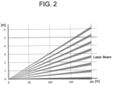
- a LIDAR having an angular resolution of 0.125 deg and a laser beam spot diameter of 0.08 deg is installed in the front portion of a vehicle to detect an obstacle, there is a gap of about 60 cm at a forward distance of 200 m as illustrated in FIG. 2 . Therefore, when a detection target object such as a pedestrian enters into the gap, there is a probability that the detection target object is not detected as an obstacle ( FIG. 3 ).
- the present invention has been made in view of such points, and an object of the present invention is to provide an obstacle detection system and an obstacle detection method for a trajectory traveling vehicle, which are capable of detecting a front obstacle on a trajectory and around the trajectory with high accuracy.
- one of representative obstacle detection systems is an obstacle detection system including: a monitoring area setting processing unit that sets an obstacle monitoring area for detecting an obstacle; a front obstacle monitoring unit that monitors an obstacle within the obstacle monitoring area by using a sensor that horizontally scans the front of a train; and an obstacle detection unit that detects an obstacle within the obstacle monitoring area based on a monitoring result of the front obstacle monitoring unit, in which the front obstacle monitoring unit complements a gap in a detection region of the sensor at a first position with the detection region of the sensor while the train moves from the first position to a second position.
- an obstacle detection system and an obstacle detection method for a trajectory traveling vehicle which are capable of detecting a front obstacle on a trajectory and around the trajectory with high accuracy.
- the detectable distance of the camera, the millimeter wave radar, or the LIDAR constituting the system depends on the color or shape of the detection target object and the reflectance of the millimeter wave or the laser, so that it is difficult to stably detect the obstacle.
- a trajectory transport system 100 that includes a transport vehicle 102, a self-position estimation system 101, a surrounding environment observation unit 107, and an obstacle detection system 103 as illustrated in FIG. 5 , and greatly improves reliability of obstacle detection of an obstacle detection system will be described.
- the transport vehicle 102 is a vehicle that travels along a trajectory and transports passengers and freight.
- the surrounding environment observation unit 107 is a device that is installed in front of the transport vehicle 102 and acquires the position, the shape, the color, the reflectance, and the like of an object around the transport vehicle 102.
- the surrounding environment observation unit 107 includes a camera, a laser radar, or a millimeter wave radar.
- the obstacle detection system 103 is a system that detects an obstacle based on position/speed information 153 of the transport vehicle 102 acquired from the self-position estimation system 101.
- the transport vehicle 102 includes a transport vehicle driving control unit 105 and a transport vehicle braking/driving unit 106.
- the obstacle detection system 103 includes a detection range setting database 108, a monitoring area setting processing unit 109, a front obstacle monitoring unit 112, and an obstacle detection unit 113.
- the transport vehicle driving control unit 105 is means for generating a braking/driving command of the transport vehicle 102.
- An ATO device (automatic train operation device) is exemplified.
- a generated transport vehicle braking/driving command 142 is transmitted to the transport vehicle braking/driving unit 106.
- the transport vehicle driving control unit 105 generates a braking/driving command so that the - transport vehicle 102 travels along a target travel pattern defined by the position and the speed.
- a function of detecting the position and the speed of the transport vehicle 102 is provided therein.
- the target travel pattern is generated based on a pattern based on the acceleration/deceleration of the transport vehicle 102 and the speed limit of a traveling section known in advance.
- the allowable maximum speed of the transport vehicle 102 is calculated from the position of the transport vehicle 102 and the maximum deceleration of the transport vehicle 102, and the calculated allowable maximum speed is reflected in the target travel pattern of the transport vehicle 102.
- the transport vehicle braking/driving unit 106 brakes and drives the transport vehicle 102 based on the transport vehicle braking/driving command 142 acquired from the transport vehicle driving control unit 105.
- Specific examples of the transportation vehicle braking/driving unit 106 include an inverter, a motor, and a friction brake.
- the obstacle detection information 161 is input from the obstacle detection unit 113 to the transport vehicle braking/driving unit 106.
- the transport vehicle 102 is stopped at a station and the content of the obstacle detection information 161 is "obstacle: existence", regardless of the transport vehicle braking/driving command 142, the transport vehicle 102 is turned into a braking state so that the vehicle cannot start.
- the transport vehicle 102 travels between stations and the content of the obstacle detection information 161 is "obstacle: existence”, regardless of the transport vehicle braking/driving command 142, braking is performed at the maximum deceleration to stop the transport vehicle 102.
- the monitoring area setting processing unit 109 acquires a detection range 154 corresponding to a current position/speed 153 of the transport vehicle, which is estimated by the self-position estimation system 101 from the detection range setting database 108, and sets an obstacle monitoring area for detecting an obstacle. Among pieces of the detection target data 157, detection target data in which the position of a detection target is within the obstacle monitoring area is transferred to the front obstacle monitoring unit 112, as detection target data 155 within the obstacle monitoring area.
- the detection range setting database 108 is, for example, based on the registration of the construction limit, and an area near the home, an area in which maintenance work is performed, and the like are registered as an area in which no detection is performed.
- the front obstacle monitoring unit 112 has a function of detecting an obstacle in the obstacle monitoring area by using a camera, a laser radar, or the like.
- the front obstacle monitoring unit 112 may share a sensor with the surrounding environment observation unit 107.
- the obstacle detection unit 113 detects an obstacle in the obstacle monitoring area based on the monitoring result 159 of the front obstacle monitoring unit 112.
- the obstacle detection unit 113 When detecting an obstacle that hinders the operation of the transport vehicle 102, the obstacle detection unit 113 transmits information of "obstacle: existence" to the transport vehicle braking/driving unit 106.
- FIG. 6 a flow of processing of the transport vehicle driving control unit 105 will be described with reference to FIG. 6 .
- the processing illustrated in FIG. 6 is performed at a regular cycle.
- Step 300 a transport vehicle on-track position is acquired.
- Step 301 it is determined whether or not the transport vehicle 102 is stopped at a station. The determination is made from the position and the speed of the transport, vehicle 102, which are stored by the transport vehicle driving control unit 105. Specifically, when the position is near the station and the speed is zero, it is determined that the vehicle is stopped at the station.
- Step 302. the scheduled time at which the transport vehicle departs from the currently stopped station is acquired from an operation management system (not illustrated in FIG. 5 ).
- Step 303 it is determined whether or not the current time has passed the scheduled departure time acquired in Step 302.
- the processing flow is ended.
- the process proceeds to Step 304.
- Step 304 it is determined whether or not the transport vehicle 102 has completed departure preparations.
- the departure preparation check of a vehicle door closed state can be exemplified.
- the processing flow is ended.
- the process proceeds to Step 305.
- Step 305 a transport vehicle braking/driving command 142 is calculated and transmitted to the transport vehicle braking/driving unit 106. Specifically, here, a powering command is transmitted in order to depart from the station.
- Step 311 a process (Step 311) when the transport vehicle 102 is not stopped at the station in Step 301 will be described.
- Step 311 the transport vehicle braking/driving command 142 is calculated and transmitted to the transport vehicle braking/driving unit 106.
- the target speed is calculated based on the position of the transport vehicle 102 and a target travel pattern defined in advance.
- the braking/driving command is calculated by proportional control or the like so that the speed of the transport vehicle 102 becomes the target speed.
- FIG. 7 is a flowchart illustrating a processing procedure performed by the obstacle detection system 103.
- Steps 201 to 210 a stop instruction for the transport vehicle is created. This processing is performed for each measurement cycle of the obstacle detection system 103.
- Step 201 the current position and speed of the transport vehicle 102 necessary for calculating the obstacle detection range are acquired from the self-position estimation system 101.
- Step 202 an obstacle monitoring area is set from a detection range corresponding to the current position of the transport vehicle, which has been acquired in Step 201.
- a construction limit as a side boundary of the obstacle monitoring area and set a stoppable distance of the transport vehicle as a traveling direction boundary of the obstacle monitoring area.
- Step 203 the number m of times of sampling is calculated for each direction ⁇ of a laser beam (spot diameter ⁇ L ) emitted from the LIDAR installed in the vehicle at a speed V ( FIG. 8 ).
- the number m of times of sampling for complementing a gap ⁇ g between laser beams at a distance L s is obtained by Expression 1 (sampling period ⁇ t).
- m L s 1 ⁇ tan ⁇ ⁇ ⁇ ⁇ L / 2 ⁇ ⁇ ⁇ g / tan ⁇ ⁇ ⁇ L / 2 / V ⁇ ⁇ t
- FIG. 8(a) attention is paid to a laser beam having a width ⁇ L , which is emitted in a ⁇ direction from a LIDAR installed in front of a train.
- the train is repeatedly measured by the LIDAR while moving forward until the right end of the beam in the ⁇ direction comes into contact with the left end of the adjacent beam, so that an obstacle between gaps ⁇ g can be detected.
- a sensor position before the movement is set as A'
- a sensor position after the movement is set as B'
- the right end of the beam in the ⁇ direction at the distance L s is set as A
- the left end of the adjacent beam is set as B.
- triangles ACA' and BCB' are similar triangles, and thus Expression 2 is established ( FIG. 25 ).
- Equation 4 is obtained from FIG. 29 .
- c ′ ⁇ a ′ L s ⁇ V ⁇ m ⁇ ⁇ t
- the gap between the laser beams is smaller than the width of the obstacle by the integration of the LIDAR data, and that the movement distance L at which the vehicle travels while measuring the gap between the laser beams is shorter than a movement distance V t ⁇ t a at which the vehicle travels within the required allowable time t a of obstacle detection.
- a non-detection range (width d t [m]) is generated, and it is not possible to detect an obstacle smaller than the width dt.
- the allowable time t a can be, for example, a time required for the train to travel at the speed V t by subtracting the stop distance at the speed V t of the train from the detection distance of the LIDAR.
- FIG. 12 illustrates an example of a relationship between the movement distance L necessary for complementing the gap between the laser beams, the train speed V t , and the detection allowable time t a .
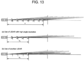
- L can be reduced by using the LIDAR having a small angle pitch and a large laser spot, light (L a in FIG. 13(a) ).
- L can also be reduced by adding a sensor that normally observes only the front direction (L b in FIG. 13(b) ).
- another LIDAR is installed in front of the train such that the laser scan plane is perpendicular to the road surface (such that the major axis of the laser spot light is parallel to the road surface), thereby the occurrence of an obstacle in the non-detection range can be monitored.
- V t As the train speed V t increases, the idling distance particularly increases in the train, and the allowable time t a that can be used for obstacle detection rapidly decreases. As a result, V t ⁇ t a tends to decrease as the train speed Vt increases, and a LIDAR obstacle detection system needs to be configured such that L decreases accordingly in consideration of the maximum speed.
- Step 204 an obstacle detection position (vehicle coordinate system) in the obstacle monitoring area calculated in Step 202 is acquired for each.direction of the laser beam emitted from the LIDAR.
- (Condition 3) is used in general obstacle detection in the automobile field and the like.
- the vehicle travels on the known trajectory in the railway field, it is possible to detect an obstacle by (Condition 1) and (Condition 2).
- the position and the reflectance of the detection target are recorded in advance in the detection target information database 110 as the detection target data 157.
- the detection target is used to determine the occurrence of the obstacle.
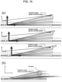
- Step 205 as illustrated in FIG. 15 (a) , after the detection position (vehicle coordinate system) is transformed into an external coordinate system, the detection positions (external coordinate system) corresponding to the number of times of sampling calculated in Step 203 are accumulated.
- Step 206 as illustrated in FIG. 15(b) , the detection positions (external coordinate system) acquired and accumulated in all directions of the laser beam are grouped.
- Step 207 as illustrated in FIG. 16 , the positions (external coordinate system) of the obstacles grouped in Step 206 are transformed into the vehicle coordinate system.
- Step 208 it is determined whether there is an obstacle in the obstacle monitoring area based on the obstacle information acquired in Step 207.
- the transport vehicle needs to be stopped, and thus obstacle detection information is created in Step 209.
- the process proceeds to Step 210.
- Step 210 the obstacle detection information in the obstacle monitoring area is transmitted to the transport vehicle 102.
- FIG. 17 is a flowchart illustrating a processing procedure performed by the self-position estimation system 101.
- Steps 401 to 404 the self-position of the transport vehicle is estimated. This processing is performed for each measurement cycle of the obstacle detection system 103.
- Step 401 the surrounding environment observation data 151 observed by the surrounding environment observation unit 107 is acquired.
- the gap in the detection region of the sensors may be complemented with detection region from a plurality of positions due to the movement of the train.
- Step 402 the surrounding environment observation data acquired in Step 401 is sorted into observation data of a known object and observation data of other unknown objects.
- Step 403 the observation data of the known object is transformed from the vehicle coordinate system to the external coordinate system.
- the surrounding environment observation data 151 is transformed from the vehicle coordinate system ⁇ T fixed to the transport vehicle 102 into the external coordinate system ⁇ o in which the positions of the detection target object and the trajectory recorded in the detection target information database 110 and a trajectory information database 111 are defined.
- Step 404 the surrounding environment observation data in the external coordinate system ⁇ o calculated in Step 403 is matched with the surrounding environment map 152 recorded as the detection target data in the detection target information database 110, and the vehicle self-position on the trajectory recorded in the trajectory information database is estimated.
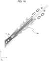
- Step 404 for example, when the surrounding environment in FIG. 18 is observed by a multi-layer LIDAR, point cloud data defined by the external coordinate system ⁇ o as illustrated in FIG. 19 can be acquired.
- the estimated self-position is normally on the trajectory, and it is possible to prevent deviation of the estimated self-position from the trajectory and erroneous detection, of an object outside the detection range, as in the influence of multipath in the case of using the GNSS.
- the obstacle detection system 103 and the trajectory transport system 100 have been described above.
- the present invention is not limited to the above embodiment, and various modification examples may be provided.
- the above embodiments are described in detail in order to explain the present invention in an easy-to-understand manner, and the above embodiments are not necessarily limited to a case including all the described configurations.
- other components can be added, deleted, and replaced.
Landscapes
- Engineering & Computer Science (AREA)
- Physics & Mathematics (AREA)
- General Physics & Mathematics (AREA)
- Electromagnetism (AREA)
- Radar, Positioning & Navigation (AREA)
- Remote Sensing (AREA)
- Mechanical Engineering (AREA)
- Computer Networks & Wireless Communication (AREA)
- Theoretical Computer Science (AREA)
- Multimedia (AREA)
- Optical Radar Systems And Details Thereof (AREA)
- Train Traffic Observation, Control, And Security (AREA)
- Traffic Control Systems (AREA)
- Radar Systems Or Details Thereof (AREA)
Abstract
Description
- The present invention relates to an obstacle detection system and an obstacle detection method for detecting an obstacle while traveling on a trajectory, and a self-position estimation system that estimates a self-position while traveling on a trajectory.
- In a trajectory transport system that travels on a trajectory, when there is an obstacle on or near the trajectory or an obstacle that may cross the trajectory, it is not possible to avoid the obstacle by steering. Therefore, it is important to detect the obstacle in order to improve the safety and operability of a train. Conventionally, an operator operates a train by visually checking that there is no obstacle on a trajectory and on a route. However, it is difficult to constantly monitor all obstacles on the traveling road surface including the vicinity, and there is a concern that the finding of the obstacle is delayed and the trajectory transport system collides with the obstacle.
- In an obstacle detection technique in a railway, there is known an obstacle detection system that automatically stops an inspection vehicle that travels before a business vehicle starts traveling when there is an obstacle within a construction limit (in order to secure the safety of a train operation, a prescribed range in which buildings or the like that may be obstacles must not be installed) when whether or not a rail has an abnormality is checked by automatic traveling. For example, in an obstacle detection system disclosed in
PTL 1, a technique of detecting an obstacle from a short distance image capturing unit that is provided in a vehicle and captures an image at a short distance while causing the vehicle to be self-propelled, a long distance image capturing unit that captures an image at a long distance, and a LIDAR that further irradiates the inside of the short distance. -
PTL 1 discloses a technique of setting a determination line at a plurality of distances in front of a vehicle and determining an object as an obstacle when the object crosses the determination line. - In addition, research on an obstacle detection system in front, of a vehicle is being conducted for automatic driving of an automobile. In the research, a camera, a millimeter wave radar, a LIDAR, and the like are generally used, and detection distances of such sensors are disclosed in various media. For example, a millimeter-wave radar or a camera which is a sensor having a long detection distance can detect a long distance of about 200 m.
- PTL 1:
JP 2016-88183 A - Since the braking distance of the vehicle in the railway is longer than that of an automobile or the like, a longer detection distance is required, but at this time, a large gap may occur between laser beams of the LIDAR. For example, as illustrated in
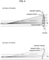
FIG. 1 , when a LIDAR having an angular resolution of 0.125 deg and a laser beam spot diameter of 0.08 deg is installed in the front portion of a vehicle to detect an obstacle, there is a gap of about 60 cm at a forward distance of 200 m as illustrated inFIG. 2 . Therefore, when a detection target object such as a pedestrian enters into the gap, there is a probability that the detection target object is not detected as an obstacle (FIG. 3 ). Since there is a gap between the adjacent laser beams of the LIDAR as described above, for example, in a case where two pedestrians cross a far point in front of the train side by side as an obstacle, detection (a circle in the figure) and non-detection (a cross in the figure) are alternately repeated as illustrated inFIG. 4(A) . As a result, when the detection point groups by the LIDAR are grouped, they are detected as the same obstacle (pedestrian), and there is a probability that the position includes a large error. - On the other hand, even in a case where there is one pedestrian, tracking of the obstacle may become unstable depending on the behavior of the pedestrian (
FIG. 4(B) ). - In the technique of
PTL 1, a case where there is a gap between laser beams of such a LIDAR has not been researched, and it is difficult to completely detect an obstacle on a trajectory. - The present invention has been made in view of such points, and an object of the present invention is to provide an obstacle detection system and an obstacle detection method for a trajectory traveling vehicle, which are capable of detecting a front obstacle on a trajectory and around the trajectory with high accuracy.
- In order to solve the above problem, one of representative obstacle detection systems according to the present invention is an obstacle detection system including: a monitoring area setting processing unit that sets an obstacle monitoring area for detecting an obstacle; a front obstacle monitoring unit that monitors an obstacle within the obstacle monitoring area by using a sensor that horizontally scans the front of a train; and an obstacle detection unit that detects an obstacle within the obstacle monitoring area based on a monitoring result of the front obstacle monitoring unit, in which the front obstacle monitoring unit complements a gap in a detection region of the sensor at a first position with the detection region of the sensor while the train moves from the first position to a second position.
- According to the present invention, it is possible to provide an obstacle detection system and an obstacle detection method for a trajectory traveling vehicle, which are capable of detecting a front obstacle on a trajectory and around the trajectory with high accuracy.
- Objects, configurations, and advantageous effects other than those described above will be clarified by the descriptions of the following embodiments.
-
- [
FIG. 1] FIG. 1 is a diagram illustrating an example of installation of an obstacle sensor in an obstacle detection system and a trajectory transport system according to an embodiment. - [
FIG. 2] FIG. 2 is a diagram illustrating an example of a gap in a detection region of an obstacle sensor. - [
FIG. 3] FIG. 3 is a diagram illustrating an example of non-detection of an obstacle when there is a gap in the detection region of the obstacle sensor. - [
FIG. 4] FIG. 4 is an explanatory diagram of an influence of the non-detection of the obstacle when there is the gap in the detection region of the obstacle sensor. - [
FIG. 5] FIG. 5 is a diagram illustrating an example of a system configuration of the trajectory transport system in the embodiment. - [
FIG. 6] FIG. 6 is a diagram illustrating an example of a processing flow of a transport vehicle driving control unit in the obstacle detection system and the trajectory transport system in the embodiment. - [
FIG. 7] FIG. 7 is a diagram illustrating an example of a processing flow of the obstacle detection system in the embodiment. - [
FIG. 8] FIG. 8 is a diagram illustrating an example of processing of complementing a gap in a detection region of the obstacle sensor. - [
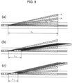
FIG. 9] FIG. 9 is an explanatory diagram of a change in a movement distance necessary for complementing a gap in a region due to a difference in a detection direction of the obstacle sensor. - [
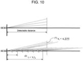
FIG. 10] FIG. 10 is an explanatory diagram of conditions necessary for complementing a gap in the detection region of the obstacle sensor with observation results from a plurality of positions during movement. - [
FIG. 11] FIG. 11 is an explanatory diagram of conditions necessary for complementing a gap in a direction close to a traveling direction among gaps in the detection region of the obstacle sensor with observation results from a plurality of positions during movement. - [
FIG. 12] FIG. 12 is a diagram illustrating an example of a relationship between a movement distance L necessary for complementing a gap between laser beams, a train speed Vt, and a detection allowable time ta. - [
FIG. 13] FIG. 13 is a diagram illustrating an example of a system configuration of an obstacle detection system that shortens a movement distance L necessary for complementing the gap between the laser beams. - [
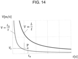
FIG. 14] FIG. 14 is a diagram illustrating a relationship among Lb, the train speed Vt, and the detection allowable time ta in the system configuration of the obstacle detection system that shortens the movement distance L necessary for complementing the gap between the laser beams. - [
FIG. 15] FIG. 15 is an explanatory diagram of grouping pieces of obstacle information in the obstacle detection system in the embodiment. - [
FIG. 16] FIG. 16 is an explanatory diagram of transformation of a grouping result into a vehicle coordinate system in the obstacle detection system in the embodiment. - [
FIG. 17] FIG. 17 is a diagram illustrating an example of a processing flow of a self-position estimation system in the embodiment. - [
FIG. 18] FIG. 18 is a diagram illustrating an example of a surrounding environment in which a transport vehicle travels in the embodiment. - [
FIG. 19] FIG. 19 is a diagram illustrating an example of surrounding environment observation data by the self-position estimation system in the embodiment. - [
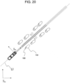
FIG. 20] FIG. 20 is a diagram illustrating an example (before matching) of matching between the surrounding environment observation data and surrounding environment map data in the self-position estimation system in the embodiment. - [
FIG. 21] FIG. 21 is a diagram illustrating an example (after matching) of the matching between the surrounding environment observation data and the surrounding environment map data in the self-position estimation system in the embodiment. - [
FIG. 22] FIG. 22 is a diagram illustrating an example (before matching) of matching between the surrounding environment observation data and surrounding environment map data in the self-position estimation system of an automobile. - [
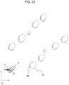
FIG. 23] FIG. 23 is a diagram illustrating an example (after matching) of matching between the surrounding environment observation data and surrounding environment map data in the self-position estimation system of the automobile. - [
FIG. 24] FIG. 24 is an explanatory diagram of a method of obtainingExpression 1. - [
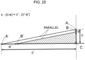
FIG. 25] FIG. 25 is an explanatory diagram of the method of obtainingExpression 1. - [
FIG. 26] FIG. 26 is an explanatory diagram of the method of obtainingExpression 1. - [
FIG. 27] FIG. 27 is an explanatory diagram of the method of obtainingExpression 1. - [
FIG. 28] FIG. 28 is an explanatory diagram of the method of obtainingExpression 1. - [
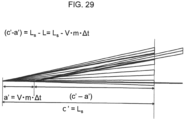
FIG. 29] FIG. 29 is an explanatory diagram of the method of obtainingExpression 1. - Hereinafter, embodiments of an obstacle detection system and an obstacle detection method capable of detecting a front obstacle on a trajectory and around the trajectory with high accuracy, and a self-position estimation system capable of estimating a self-position with high accuracy will be described.
- In the conventional obstacle detection system, the detectable distance of the camera, the millimeter wave radar, or the LIDAR constituting the system depends on the color or shape of the detection target object and the reflectance of the millimeter wave or the laser, so that it is difficult to stably detect the obstacle.
- In the obstacle detection system and the obstacle detection method according to the embodiments described below, it is possible to detect an obstacle without depending on the color, the shape, or the reflectance of a detection target object.
- Hereinafter, embodiments will be described with reference to the drawings.
- In the present embodiment, a
trajectory transport system 100 that includes atransport vehicle 102, a self-position estimation system 101, a surroundingenvironment observation unit 107, and anobstacle detection system 103 as illustrated inFIG. 5 , and greatly improves reliability of obstacle detection of an obstacle detection system will be described. - First, a configuration of the
trajectory transport system 100 and the function of each component will be described with reference toFIG. 5 . - The
transport vehicle 102 is a vehicle that travels along a trajectory and transports passengers and freight. - The surrounding
environment observation unit 107 is a device that is installed in front of thetransport vehicle 102 and acquires the position, the shape, the color, the reflectance, and the like of an object around thetransport vehicle 102. The surroundingenvironment observation unit 107 includes a camera, a laser radar, or a millimeter wave radar. - The
obstacle detection system 103 is a system that detects an obstacle based on position/speed information 153 of thetransport vehicle 102 acquired from the self-position estimation system 101. - When the
obstacle detection system 103 detects an obstacle that hinders traveling of thetransport vehicle 102, information on the existence of the obstacle is transmitted from theobstacle detection system 103 to thetransport vehicle 102, and thetransport vehicle 102 is brought to an emergency stop. Thetransport vehicle 102 includes a transport vehicle drivingcontrol unit 105 and a transport vehicle braking/driving unit 106. - The
obstacle detection system 103 includes a detectionrange setting database 108, a monitoring areasetting processing unit 109, a frontobstacle monitoring unit 112, and anobstacle detection unit 113. - The transport vehicle driving
control unit 105 is means for generating a braking/driving command of thetransport vehicle 102. An ATO device (automatic train operation device) is exemplified. A generated transport vehicle braking/driving command 142 is transmitted to the transport vehicle braking/driving unit 106. - The transport vehicle driving
control unit 105 generates a braking/driving command so that the -transport vehicle 102 travels along a target travel pattern defined by the position and the speed. Although not illustrated inFIG. 5 , in order to travel along the target travel pattern, a function of detecting the position and the speed of thetransport vehicle 102 is provided therein. - The target travel pattern is generated based on a pattern based on the acceleration/deceleration of the
transport vehicle 102 and the speed limit of a traveling section known in advance. In addition, the allowable maximum speed of thetransport vehicle 102 is calculated from the position of thetransport vehicle 102 and the maximum deceleration of thetransport vehicle 102, and the calculated allowable maximum speed is reflected in the target travel pattern of thetransport vehicle 102. - The transport vehicle braking/
driving unit 106 brakes and drives thetransport vehicle 102 based on the transport vehicle braking/driving command 142 acquired from the transport vehicle drivingcontrol unit 105. Specific examples of the transportation vehicle braking/driving unit 106 include an inverter, a motor, and a friction brake. - The
obstacle detection information 161 is input from theobstacle detection unit 113 to the transport vehicle braking/driving unit 106. When thetransport vehicle 102 is stopped at a station and the content of theobstacle detection information 161 is "obstacle: existence", regardless of the transport vehicle braking/driving command 142, thetransport vehicle 102 is turned into a braking state so that the vehicle cannot start. When thetransport vehicle 102 travels between stations and the content of theobstacle detection information 161 is "obstacle: existence", regardless of the transport vehicle braking/driving command 142, braking is performed at the maximum deceleration to stop thetransport vehicle 102. - The monitoring area
setting processing unit 109 acquires adetection range 154 corresponding to a current position/speed 153 of the transport vehicle, which is estimated by the self-position estimation system 101 from the detectionrange setting database 108, and sets an obstacle monitoring area for detecting an obstacle. Among pieces of thedetection target data 157, detection target data in which the position of a detection target is within the obstacle monitoring area is transferred to the frontobstacle monitoring unit 112, asdetection target data 155 within the obstacle monitoring area. - It is conceivable that the detection
range setting database 108 is, for example, based on the registration of the construction limit, and an area near the home, an area in which maintenance work is performed, and the like are registered as an area in which no detection is performed. - The front
obstacle monitoring unit 112 has a function of detecting an obstacle in the obstacle monitoring area by using a camera, a laser radar, or the like. Here, the frontobstacle monitoring unit 112 may share a sensor with the surroundingenvironment observation unit 107. - The
obstacle detection unit 113 detects an obstacle in the obstacle monitoring area based on themonitoring result 159 of the frontobstacle monitoring unit 112. - When detecting an obstacle that hinders the operation of the
transport vehicle 102, theobstacle detection unit 113 transmits information of "obstacle: existence" to the transport vehicle braking/driving unit 106. - The configuration and each component of the
trajectory transport system 100 have been described above. - Next, a flow of processing of the transport vehicle driving
control unit 105 will be described with reference toFIG. 6 . In the transport vehicle drivingcontrol unit 105, the processing illustrated inFIG. 6 is performed at a regular cycle. - In
Step 300, a transport vehicle on-track position is acquired. - In
Step 301, it is determined whether or not thetransport vehicle 102 is stopped at a station. The determination is made from the position and the speed of the transport,vehicle 102, which are stored by the transport vehicle drivingcontrol unit 105. Specifically, when the position is near the station and the speed is zero, it is determined that the vehicle is stopped at the station. - When it is determined in
Step 301 that thetransport vehicle 102 is being stopped, in Step 302., the scheduled time at which the transport vehicle departs from the currently stopped station is acquired from an operation management system (not illustrated inFIG. 5 ). - In
Step 303, it is determined whether or not the current time has passed the scheduled departure time acquired inStep 302. When the current time has not passed the scheduled departure time, the processing flow is ended. When the current time has passed the scheduled departure time, the process proceeds to Step 304. - In
Step 304, it is determined whether or not thetransport vehicle 102 has completed departure preparations. As an example of the departure preparation, check of a vehicle door closed state can be exemplified. When thetransport vehicle 102 has not completed departure preparations yet, the processing flow is ended. When the departure preparation has completed, the process proceeds to Step 305. - In
Step 305, a transport vehicle braking/driving command 142 is calculated and transmitted to the transport vehicle braking/driving unit 106. Specifically, here, a powering command is transmitted in order to depart from the station. - Next, a process (Step 311) when the
transport vehicle 102 is not stopped at the station inStep 301 will be described. - In
Step 311, the transport vehicle braking/driving command 142 is calculated and transmitted to the transport vehicle braking/driving unit 106. Specifically, here, first, the target speed is calculated based on the position of thetransport vehicle 102 and a target travel pattern defined in advance. The braking/driving command is calculated by proportional control or the like so that the speed of thetransport vehicle 102 becomes the target speed. - The example of the control flow of the transport vehicle driving
control unit 105 has been described above. - Next, the operation of the
obstacle detection system 103 will be described.FIG. 7 is a flowchart illustrating a processing procedure performed by theobstacle detection system 103. - In
Steps 201 to 210, a stop instruction for the transport vehicle is created. This processing is performed for each measurement cycle of theobstacle detection system 103. - In
Step 201, the current position and speed of thetransport vehicle 102 necessary for calculating the obstacle detection range are acquired from the self-position estimation system 101. - In
Step 202, an obstacle monitoring area is set from a detection range corresponding to the current position of the transport vehicle, which has been acquired inStep 201. - For example, it is conceivable to set a construction limit as a side boundary of the obstacle monitoring area and set a stoppable distance of the transport vehicle as a traveling direction boundary of the obstacle monitoring area.
- In
Step 203, the number m of times of sampling is calculated for each direction θ of a laser beam (spot diameter ΔθL) emitted from the LIDAR installed in the vehicle at a speed V (FIG. 8 ). The number m of times of sampling for complementing a gap Δθg between laser beams at a distance Ls is obtained by Expression 1 (sampling period Δt).
- A method of obtaining
Expression 1 will be described. - As illustrated in
FIG. 8(a) , attention is paid to a laser beam having a width ΔθL, which is emitted in a θ direction from a LIDAR installed in front of a train. As illustrated inFIG. 8(b) , the train is repeatedly measured by the LIDAR while moving forward until the right end of the beam in the θ direction comes into contact with the left end of the adjacent beam, so that an obstacle between gaps Δθg can be detected. - At this time, assuming that the speed of the train is V, the number of times of measurement is m, and the measurement cycle is Δt, a movement distance L of the train can be calculated by L = V·m·Δt.
- As illustrated in
FIG. 24 , a sensor position before the movement is set as A', a sensor position after the movement is set as B' , the right end of the beam in the θ direction at the distance Ls is set as A, and the left end of the adjacent beam is set as B. When distances AB, AC, A'B', and A'C between two points are set as a, c, a', and c', respectively, triangles ACA' and BCB' are similar triangles, and thusExpression 2 is established (FIG. 25 ).
- Here, from
FIGS. 26 and27 , c = Ls·tan(θ - ΔθL/2) and c' = Ls, and, as is clear fromFIG. 28 ,Expression 3 is established.
- In addition, Equation 4 is obtained from
FIG. 29 .
- The variables are substituted into
Expression 2 and solved for m as follows.


- Thus,
Expression 1 has been obtained. - Here, in the calculation of the number of times of sampling based on the vehicle speed, it is important that the gap between the laser beams is smaller than the width of the obstacle by the integration of the LIDAR data, and that the movement distance L at which the vehicle travels while measuring the gap between the laser beams is shorter than a movement distance Vt × ta at which the vehicle travels within the required allowable time ta of obstacle detection.
- As illustrated in
FIG. 9 (a) , as the detection direction by the LIDAR becomes far away from the traveling direction from θa to θb, the necessary movement distance gradually decreases from La to Lb as illustrated inFIGS. 9(b) and 9 (c) . This means that, when measurement is performed by the LIDAR from a train traveling at a predetermined speed, the number of times of measurement in the same gap decreases as the distance from the traveling direction increases. - That is, as illustrated in
FIG. 10(1) , it is necessary to shorten the sampling period of the LIDAR so as to enable securing of the number of times of measurement in which a distance dL between the laser beams becomes smaller than a width do of the target obstacle. - on the other hand, as the laser beam irradiation direction of the LIDAR is closer to the traveling direction than in a case where the laser beam irradiation direction is separated in a ties direction, a longer movement distance L of the train (a distance at which complementation of the gaps between the laser beams is completed) is required to detect an obstacle in the gap between the laser beams as illustrated in
FIG. 10 (2) . In order to be able to output the obstacle detection result within the requested allowable time ta, when the speed of the train is set as Vt, L < Vt × ta must be satisfied. Depending on the magnitudes of Vt and ta, when Vt × ta < L is satisfied as illustrated inFIG. 11 , a non-detection range (width dt[m]) is generated, and it is not possible to detect an obstacle smaller than the width dt. The allowable time ta can be, for example, a time required for the train to travel at the speed Vt by subtracting the stop distance at the speed Vt of the train from the detection distance of the LIDAR. -
FIG. 12 illustrates an example of a relationship between the movement distance L necessary for complementing the gap between the laser beams, the train speed Vt, and the detection allowable time ta. The point P(Vt, ta) needs to be in the upper right region of the curve V = L/t (hatched portion in the drawing). - Here, L can be reduced by using the LIDAR having a small angle pitch and a large laser spot, light (La in
FIG. 13(a) ). However, there is a problem that the sampling period becomes longer by the amount or it is not possible to measure a small obstacle because the laser spot light is large. On the other hand, L can also be reduced by adding a sensor that normally observes only the front direction (Lb inFIG. 13(b) ). As an example, another LIDAR is installed in front of the train such that the laser scan plane is perpendicular to the road surface (such that the major axis of the laser spot light is parallel to the road surface), thereby the occurrence of an obstacle in the non-detection range can be monitored. InFIG. 13 , as the movement distance changes from L to Lb, the point P(Vt, ta) is located in the upper right region of the curve V = L/t as illustrated inFIG. 14 . - As the train speed Vt increases, the idling distance particularly increases in the train, and the allowable time ta that can be used for obstacle detection rapidly decreases. As a result, Vt × ta tends to decrease as the train speed Vt increases, and a LIDAR obstacle detection system needs to be configured such that L decreases accordingly in consideration of the maximum speed.
- In
Step 204, an obstacle detection position (vehicle coordinate system) in the obstacle monitoring area calculated inStep 202 is acquired for each.direction of the laser beam emitted from the LIDAR. - When the detection result in the monitoring area satisfies any one of (Condition 1) to (Condition 3) below compared with the detection target data registered in the detection target information database, it is determined that an obstacle has occurred.
- (Condition 1) The known detection point registered in the database is not detected. (Condition 2) The reflectance of the known detection point is different. (Condition 3) A detection point is detected at a position different from the known detection point.
- (Condition 3) is used in general obstacle detection in the automobile field and the like. On the other hand, since the vehicle travels on the known trajectory in the railway field, it is possible to detect an obstacle by (Condition 1) and (Condition 2). For example, it is also possible to detect an obstacle near a known object or in a gap between a plurality of objects.
- Here, as the speed of the transport vehicle increases, the stop distance of the transport vehicle increases, and the obstacle monitoring area expands. When the reflectance of the known detection point located at a long distance is small, it may be erroneously determined that an obstacle has occurred due to (Condition 1). Therefore, for example, it is necessary to suppress an allowed travelable speed.
- Therefore, in order to avoid suppression of the allowed travelable speed, the following measures of (Measure 1) and (Measure 2) will be considered.
- (Measure 1) Only the position of an existing object (rail, sign, or the like) having a detection rate of a certain value or more in the detection region is set as a detection target. (Measure 2) An object having a detection rate of a certain value or more is installed in the detection region as a detection target. For example, it is conceivable that an object having a reflectance of a certain value or more has a detection rate of a certain value or more.
- In any case, the position and the reflectance of the detection target are recorded in advance in the detection
target information database 110 as thedetection target data 157. In addition, only when the position of the detection target is included in the obstacle monitoring area at the current position of the transportation vehicle, the detection target is used to determine the occurrence of the obstacle. - In
Step 205, as illustrated inFIG. 15 (a) , after the detection position (vehicle coordinate system) is transformed into an external coordinate system, the detection positions (external coordinate system) corresponding to the number of times of sampling calculated inStep 203 are accumulated. - In
Step 206, as illustrated inFIG. 15(b) , the detection positions (external coordinate system) acquired and accumulated in all directions of the laser beam are grouped. - In
Step 207, as illustrated inFIG. 16 , the positions (external coordinate system) of the obstacles grouped inStep 206 are transformed into the vehicle coordinate system. - In
Step 208, it is determined whether there is an obstacle in the obstacle monitoring area based on the obstacle information acquired inStep 207. When it is determined inStep 208 that there is the obstacle, the transport vehicle needs to be stopped, and thus obstacle detection information is created inStep 209. On the other hand, when it is determined that there is no obstacle, the process proceeds to Step 210. - In
Step 210, the obstacle detection information in the obstacle monitoring area is transmitted to thetransport vehicle 102. - The flow example of an obstacle detection operation performed by the
obstacle detection system 103 has been described above. - Next, the operation of the self-
position estimation system 101 will be described..FIG. 17 is a flowchart illustrating a processing procedure performed by the self-position estimation system 101. - In
Steps 401 to 404, the self-position of the transport vehicle is estimated. This processing is performed for each measurement cycle of theobstacle detection system 103. - In
Step 401, the surroundingenvironment observation data 151 observed by the surroundingenvironment observation unit 107 is acquired. Similarly to theobstacle detection system 103, the gap in the detection region of the sensors may be complemented with detection region from a plurality of positions due to the movement of the train. - In
Step 402, the surrounding environment observation data acquired inStep 401 is sorted into observation data of a known object and observation data of other unknown objects. - In
Step 403, the observation data of the known object is transformed from the vehicle coordinate system to the external coordinate system. The surroundingenvironment observation data 151 is transformed from the vehicle coordinate system ΣT fixed to thetransport vehicle 102 into the external coordinate system Σo in which the positions of the detection target object and the trajectory recorded in the detectiontarget information database 110 and atrajectory information database 111 are defined. - In
Step 404, the surrounding environment observation data in the external coordinate system Σo calculated inStep 403 is matched with the surroundingenvironment map 152 recorded as the detection target data in the detectiontarget information database 110, and the vehicle self-position on the trajectory recorded in the trajectory information database is estimated. - In
Step 404, for example, when the surrounding environment inFIG. 18 is observed by a multi-layer LIDAR, point cloud data defined by the external coordinate system Σo as illustrated inFIG. 19 can be acquired. - When the vehicle does not travel along a specific trajectory like an automobile, as illustrated in
FIGS. 22 and23 , it is necessary to correlate the surroundingenvironment observation data 168 with the surrounding environment map while moving the vehicle in any direction, and to obtain the position (FIG. 23 ) having the highest correlation value as the self-position. On the other hand, here, the transport vehicle travels on the trajectory. Thus, the surroundingenvironment observation data 168 and the surrounding,environment map 152 only need to be correlated with each other while moving on the trajectory LI inFIG. 20 , and the position (FIG. 21 ) having the highest correlation value only needs to be obtained as the self-position. In addition, at this time, the estimated self-position is normally on the trajectory, and it is possible to prevent deviation of the estimated self-position from the trajectory and erroneous detection, of an object outside the detection range, as in the influence of multipath in the case of using the GNSS. - The flow example of the self-position processing performed by the self-
position estimation system 101 has been described above. - The
obstacle detection system 103 and thetrajectory transport system 100 have been described above. - The present invention is not limited to the above embodiment, and various modification examples may be provided. For example, the above embodiments are described in detail in order to explain the present invention in an easy-to-understand manner, and the above embodiments are not necessarily limited to a case including all the described configurations. Regarding some components in the embodiments, other components can be added, deleted, and replaced.
-
- 100
- trajectory transport system
- 101
- self-position estimation system
- 102
- transport vehicle
- 103
- obstacle detection system
- 105
- transport vehicle driving control unit
- 106
- transport vehicle braking/driving unit
- 107
- surrounding environment observation unit
- 108
- detection range setting database
- 109
- monitoring area setting processing unit
- 110
- detection target information database
- 111
- trajectory information database
- 112
- front obstacle monitoring unit
- 113
- obstacle detection unit
- 142
- transport vehicle braking/driving command
- 151
- surrounding environment observation data
- 152
- surrounding environment map
- 153
- transport vehicle position/speed information
- 154
- obstacle detection range
- 155
- detection target data in obstacle monitoring area
- 156
- trajectory information
- 157
- detection target data
- 159
- front obstacle monitoring result
- 161
- obstacle detection information
- 168
- surrounding environment observation data
- 203
- obstacle sensor
Claims (8)
- An obstacle detection system comprising:a monitoring area setting processing unit that sets an obstacle monitoring area for detecting an obstacle;a front obstacle monitoring unit that monitors an obstacle within the obstacle monitoring area by using a sensor that horizontally scans a front of a train; andan obstacle detection unit that detects an obstacle within the obstacle monitoring area based on a monitoring result of the front obstacle monitoring unit,wherein the front obstacle monitoring unit complements a gap in a detection region of the sensor at a first position with the detection region of the sensor while the train moves from the first position to a second position.
- The obstacle detection system according to claim 1, wherein a distance between the first position and the second position is smaller than a product of a speed of the train and a time allowed to detect an obstacle.
- The obstacle detection system according to claim 2, wherein a sensor that normally uses only a front direction of the train as a detection region is used in addition to the sensor that horizontally scans a front of the train.
- The obstacle detection system according to any one of claims 1 to 3, wherein, when a detection result within the obstacle monitoring area does not coincide with detection target data registered in a database, an obstacle is detected.
- The obstacle detection system according to claim 4, wherein, when a known detection point having a detection rate equal to or higher than a threshold value is not detected, an obstacle is detected.
- The obstacle detection system according to claim 4, wherein, when reflectances of known detection points having detection rates equal to or higher than a threshold value are different, an obstacle is detected.
- An obstacle detection method using a sensor that horizontally scans a front of a train, the obstacle detection method comprising:a step of calculating an obstacle monitoring area;a step of calculating, for each direction of a detection region of the sensor, the number of times of sampling to complement a gap of the detection region based on a speed of the train;a step of acquiring a detection position of an obstacle for each direction of the detection region;a step of accumulating the detection position by the calculated number of times of sampling;a step of grouping the detection positions acquired and accumulated in all directions of the detection region; anda step of creating obstacle detection information when there is the obstacle in the obstacle monitoring area.
- A self-position estimation system using a sensor that horizontally scans a front of a train, in whichthe self-position estimation systemcomplements a gap of a detection region of the sensor at a first position with a detection region of the sensor while the train moves from the first position to a second position, andtakes, a correlation between a detection result and detection target data registered in a database, at a position of a train limited on a trajectory, andsets a position of a train having a high correlation, as a self-position.
Applications Claiming Priority (2)
| Application Number | Priority Date | Filing Date | Title |
|---|---|---|---|
| JP2020100795A JP7348881B2 (en) | 2020-06-10 | 2020-06-10 | Obstacle detection system, obstacle detection method, and self-position estimation system |
| PCT/JP2021/017198 WO2021251028A1 (en) | 2020-06-10 | 2021-04-30 | Obstacle detection system, obstacle detection method, and self-location estimation system |
Publications (2)
| Publication Number | Publication Date |
|---|---|
| EP4166416A1 true EP4166416A1 (en) | 2023-04-19 |
| EP4166416A4 EP4166416A4 (en) | 2024-07-17 |
Family
ID=78847205
Family Applications (1)
| Application Number | Title | Priority Date | Filing Date |
|---|---|---|---|
| EP21822778.3A Pending EP4166416A4 (en) | 2020-06-10 | 2021-04-30 | OBSTACLE DETECTION DEVICE, OBSTACLE DETECTION METHOD, AND SELF-LOCATION ESTIMATION SYSTEM |
Country Status (5)
| Country | Link |
|---|---|
| US (1) | US12576895B2 (en) |
| EP (1) | EP4166416A4 (en) |
| JP (1) | JP7348881B2 (en) |
| AU (1) | AU2021289307B2 (en) |
| WO (1) | WO2021251028A1 (en) |
Families Citing this family (9)
| Publication number | Priority date | Publication date | Assignee | Title |
|---|---|---|---|---|
| US20220268936A1 (en) * | 2021-02-24 | 2022-08-25 | Siemens Mobility, Inc. | End of train device and integrated lidar monitoring system |
| US11854309B2 (en) | 2021-10-30 | 2023-12-26 | Cattron North America, Inc. | Systems and methods for remotely controlling locomotives with gestures |
| JP7486556B2 (en) * | 2022-09-02 | 2024-05-17 | 本田技研工業株式会社 | Lane marking recognition device |
| KR102868425B1 (en) * | 2022-10-24 | 2025-10-13 | 한국철도기술연구원 | A system and method for determining the presence of obstacles in a collision risk zone based on a track map of an autonomous train. |
| CN115790420B (en) * | 2022-11-25 | 2026-03-03 | 惠州市德赛西威汽车电子股份有限公司 | Obstacle ranging method, obstacle ranging device, vehicle and medium |
| FR3151087B1 (en) * | 2023-07-13 | 2025-11-21 | Gts France Sas | Preceded by data processing on board a machine and using a database in which object definition data are stored, constituting reference points along a predetermined path of the machine. |
| CN118636949A (en) * | 2024-05-28 | 2024-09-13 | 中车青岛四方机车车辆股份有限公司 | A method, system, device and rail system for obtaining operating environment data |
| TWI900207B (en) * | 2024-09-03 | 2025-10-01 | 國立臺北科技大學 | Train Driving Warning Methods |
| EP4707118A1 (en) * | 2024-09-10 | 2026-03-11 | Otiv | Dynamic time-to-collision determination of a rail vehicle |
Family Cites Families (11)
| Publication number | Priority date | Publication date | Assignee | Title |
|---|---|---|---|---|
| JP3085755B2 (en) * | 1991-10-30 | 2000-09-11 | 東日本旅客鉄道株式会社 | Obstacle detection device for railway vehicles |
| JP2008026997A (en) * | 2006-07-18 | 2008-02-07 | Denso Corp | Pedestrian recognition device and pedestrian recognition method |
| TWI327536B (en) * | 2007-05-16 | 2010-07-21 | Univ Nat Defense | Device and method for detecting obstacle by stereo computer vision |
| JP5312367B2 (en) * | 2010-02-12 | 2013-10-09 | 村田機械株式会社 | Traveling cart system |
| JP5978565B2 (en) * | 2011-06-30 | 2016-08-24 | 富士通株式会社 | Monitoring device and monitoring method |
| JP6464673B2 (en) * | 2014-10-31 | 2019-02-06 | 株式会社Ihi | Obstacle detection system and railway vehicle |
| DE102014223900A1 (en) | 2014-11-24 | 2016-05-25 | Conti Temic Microelectronic Gmbh | Vehicle environment scanning using a phased array laser |
| US10338225B2 (en) * | 2015-12-15 | 2019-07-02 | Uber Technologies, Inc. | Dynamic LIDAR sensor controller |
| CN108297896B (en) * | 2017-11-30 | 2020-08-04 | 广州华夏职业学院 | Rail transit barrier early warning device |
| CN112351928B (en) * | 2018-07-10 | 2023-11-10 | 铁路视像有限公司 | Method and system for railway obstacle detection based on track segmentation |
| JP7181754B2 (en) | 2018-10-15 | 2022-12-01 | 株式会社日立製作所 | Obstacle detection system for track traveling vehicle and obstacle detection method |
-
2020
- 2020-06-10 JP JP2020100795A patent/JP7348881B2/en active Active
-
2021
- 2021-04-30 AU AU2021289307A patent/AU2021289307B2/en active Active
- 2021-04-30 EP EP21822778.3A patent/EP4166416A4/en active Pending
- 2021-04-30 WO PCT/JP2021/017198 patent/WO2021251028A1/en not_active Ceased
- 2021-04-30 US US17/927,952 patent/US12576895B2/en active Active
Also Published As
| Publication number | Publication date |
|---|---|
| WO2021251028A1 (en) | 2021-12-16 |
| AU2021289307B2 (en) | 2024-01-04 |
| EP4166416A4 (en) | 2024-07-17 |
| JP2021194939A (en) | 2021-12-27 |
| AU2021289307A1 (en) | 2023-01-19 |
| US20230202540A1 (en) | 2023-06-29 |
| JP7348881B2 (en) | 2023-09-21 |
| US12576895B2 (en) | 2026-03-17 |
Similar Documents
| Publication | Publication Date | Title |
|---|---|---|
| US12576895B2 (en) | Obstacle detection system, obstacle detection method, and self-location estimation system | |
| CN111257864B (en) | Active type detection vehicle continuous tracking breakpoint compensation device, system and method | |
| JP7227879B2 (en) | Surrounding Observation System, Surrounding Observation Program and Surrounding Observation Method | |
| US8125372B2 (en) | Driver assistance system and method for checking the plausibility of objects | |
| US10442465B2 (en) | Parking assistance device and vehicle provided with such a device | |
| US11158192B2 (en) | Method and system for detecting parking spaces which are suitable for a vehicle | |
| CN105022095B (en) | A fast-pass moving target radiation inspection method and system | |
| US12384434B2 (en) | Sensor performance evaluation system and method, and automatic driving system | |
| AU2021371394B2 (en) | Rail transportation system, method for controlling rail transportation system, and trackside facility shape measurement system | |
| US10388164B2 (en) | Method and system for detecting an unoccupied region within a parking facility | |
| US20230154199A1 (en) | Driving control system and method of controlling the same using sensor fusion between vehicles | |
| JP7181754B2 (en) | Obstacle detection system for track traveling vehicle and obstacle detection method | |
| US10713503B2 (en) | Visual object detection system | |
| US11475780B2 (en) | Airport stand arrangement and method | |
| KR102188567B1 (en) | System for monitoring the road using 3 dimension laser scanner | |
| JP7454522B2 (en) | Vehicle merging system | |
| TWI918001B (en) | Airport stand arrangement device | |
| GB2632923A (en) | Method for detecting obstacles onboard a machine adapted to move on at least one predetermined path | |
| EP4662082A1 (en) | Foreign object detection for railway | |
| WO2026042337A1 (en) | Vehicle position calculation method and vehicle position calculation system | |
| CN119781470A (en) | Emergency control method and device for automatic guided vehicle and automatic guided vehicle | |
| Escamilla-Ambrosio et al. | Sensor fusion approaches to guideway and obstacle detection in the autotaxi system |
Legal Events
| Date | Code | Title | Description |
|---|---|---|---|
| STAA | Information on the status of an ep patent application or granted ep patent |
Free format text: STATUS: THE INTERNATIONAL PUBLICATION HAS BEEN MADE |
|
| PUAI | Public reference made under article 153(3) epc to a published international application that has entered the european phase |
Free format text: ORIGINAL CODE: 0009012 |
|
| STAA | Information on the status of an ep patent application or granted ep patent |
Free format text: STATUS: REQUEST FOR EXAMINATION WAS MADE |
|
| 17P | Request for examination filed |
Effective date: 20230110 |
|
| AK | Designated contracting states |
Kind code of ref document: A1 Designated state(s): AL AT BE BG CH CY CZ DE DK EE ES FI FR GB GR HR HU IE IS IT LI LT LU LV MC MK MT NL NO PL PT RO RS SE SI SK SM TR |
|
| DAV | Request for validation of the european patent (deleted) | ||
| DAX | Request for extension of the european patent (deleted) | ||
| REG | Reference to a national code |
Ref country code: DE Ref legal event code: R079 Free format text: PREVIOUS MAIN CLASS: B61L0023000000 Ipc: G01S0017931000 |
|
| A4 | Supplementary search report drawn up and despatched |
Effective date: 20240614 |
|
| RIC1 | Information provided on ipc code assigned before grant |
Ipc: G06V 20/58 20220101ALI20240610BHEP Ipc: G01S 13/87 20060101ALI20240610BHEP Ipc: G01S 13/931 20200101ALI20240610BHEP Ipc: B61L 23/04 20060101ALI20240610BHEP Ipc: B61L 15/00 20060101ALI20240610BHEP Ipc: G01S 17/42 20060101ALI20240610BHEP Ipc: G01S 17/87 20200101ALI20240610BHEP Ipc: G01S 17/931 20200101AFI20240610BHEP |