EP4166402A1 - Brake-by-wire system including pressure balanced psu piston with wetted ball screw - Google Patents
Brake-by-wire system including pressure balanced psu piston with wetted ball screw Download PDFInfo
- Publication number
- EP4166402A1 EP4166402A1 EP22201956.4A EP22201956A EP4166402A1 EP 4166402 A1 EP4166402 A1 EP 4166402A1 EP 22201956 A EP22201956 A EP 22201956A EP 4166402 A1 EP4166402 A1 EP 4166402A1
- Authority
- EP
- European Patent Office
- Prior art keywords
- psu
- fluid
- brake
- piston
- assembly
- Prior art date
- Legal status (The legal status is an assumption and is not a legal conclusion. Google has not performed a legal analysis and makes no representation as to the accuracy of the status listed.)
- Pending
Links
- 239000012530 fluid Substances 0.000 claims abstract description 192
- 230000004044 response Effects 0.000 claims abstract description 10
- 238000004891 communication Methods 0.000 claims description 14
- 230000000903 blocking effect Effects 0.000 claims description 8
- 238000002955 isolation Methods 0.000 claims description 8
- 238000012546 transfer Methods 0.000 claims description 2
- 230000006835 compression Effects 0.000 claims 1
- 238000007906 compression Methods 0.000 claims 1
- 238000010586 diagram Methods 0.000 description 16
- 238000013461 design Methods 0.000 description 11
- 238000006073 displacement reaction Methods 0.000 description 6
- 238000013519 translation Methods 0.000 description 6
- 230000009977 dual effect Effects 0.000 description 5
- 238000005192 partition Methods 0.000 description 5
- 229920002492 poly(sulfone) Polymers 0.000 description 4
- 230000009467 reduction Effects 0.000 description 4
- 230000008878 coupling Effects 0.000 description 3
- 238000010168 coupling process Methods 0.000 description 3
- 238000005859 coupling reaction Methods 0.000 description 3
- 238000001514 detection method Methods 0.000 description 3
- 238000007667 floating Methods 0.000 description 3
- 230000001172 regenerating effect Effects 0.000 description 3
- 230000000740 bleeding effect Effects 0.000 description 2
- 238000013016 damping Methods 0.000 description 1
- 230000000694 effects Effects 0.000 description 1
- 230000008030 elimination Effects 0.000 description 1
- 238000003379 elimination reaction Methods 0.000 description 1
- 238000012905 input function Methods 0.000 description 1
- 238000000034 method Methods 0.000 description 1
- 238000002156 mixing Methods 0.000 description 1
- 238000012986 modification Methods 0.000 description 1
- 230000004048 modification Effects 0.000 description 1
- 238000012544 monitoring process Methods 0.000 description 1
- 230000008929 regeneration Effects 0.000 description 1
- 238000011069 regeneration method Methods 0.000 description 1
Images







Classifications
-
- B—PERFORMING OPERATIONS; TRANSPORTING
- B60—VEHICLES IN GENERAL
- B60T—VEHICLE BRAKE CONTROL SYSTEMS OR PARTS THEREOF; BRAKE CONTROL SYSTEMS OR PARTS THEREOF, IN GENERAL; ARRANGEMENT OF BRAKING ELEMENTS ON VEHICLES IN GENERAL; PORTABLE DEVICES FOR PREVENTING UNWANTED MOVEMENT OF VEHICLES; VEHICLE MODIFICATIONS TO FACILITATE COOLING OF BRAKES
- B60T13/00—Transmitting braking action from initiating means to ultimate brake actuator with power assistance or drive; Brake systems incorporating such transmitting means, e.g. air-pressure brake systems
- B60T13/74—Transmitting braking action from initiating means to ultimate brake actuator with power assistance or drive; Brake systems incorporating such transmitting means, e.g. air-pressure brake systems with electrical assistance or drive
- B60T13/745—Transmitting braking action from initiating means to ultimate brake actuator with power assistance or drive; Brake systems incorporating such transmitting means, e.g. air-pressure brake systems with electrical assistance or drive acting on a hydraulic system, e.g. a master cylinder
-
- B—PERFORMING OPERATIONS; TRANSPORTING
- B60—VEHICLES IN GENERAL
- B60T—VEHICLE BRAKE CONTROL SYSTEMS OR PARTS THEREOF; BRAKE CONTROL SYSTEMS OR PARTS THEREOF, IN GENERAL; ARRANGEMENT OF BRAKING ELEMENTS ON VEHICLES IN GENERAL; PORTABLE DEVICES FOR PREVENTING UNWANTED MOVEMENT OF VEHICLES; VEHICLE MODIFICATIONS TO FACILITATE COOLING OF BRAKES
- B60T13/00—Transmitting braking action from initiating means to ultimate brake actuator with power assistance or drive; Brake systems incorporating such transmitting means, e.g. air-pressure brake systems
- B60T13/10—Transmitting braking action from initiating means to ultimate brake actuator with power assistance or drive; Brake systems incorporating such transmitting means, e.g. air-pressure brake systems with fluid assistance, drive, or release
- B60T13/12—Transmitting braking action from initiating means to ultimate brake actuator with power assistance or drive; Brake systems incorporating such transmitting means, e.g. air-pressure brake systems with fluid assistance, drive, or release the fluid being liquid
- B60T13/16—Transmitting braking action from initiating means to ultimate brake actuator with power assistance or drive; Brake systems incorporating such transmitting means, e.g. air-pressure brake systems with fluid assistance, drive, or release the fluid being liquid using pumps directly, i.e. without interposition of accumulators or reservoirs
- B60T13/168—Arrangements for pressure supply
-
- B—PERFORMING OPERATIONS; TRANSPORTING
- B60—VEHICLES IN GENERAL
- B60T—VEHICLE BRAKE CONTROL SYSTEMS OR PARTS THEREOF; BRAKE CONTROL SYSTEMS OR PARTS THEREOF, IN GENERAL; ARRANGEMENT OF BRAKING ELEMENTS ON VEHICLES IN GENERAL; PORTABLE DEVICES FOR PREVENTING UNWANTED MOVEMENT OF VEHICLES; VEHICLE MODIFICATIONS TO FACILITATE COOLING OF BRAKES
- B60T11/00—Transmitting braking action from initiating means to ultimate brake actuator without power assistance or drive or where such assistance or drive is irrelevant
- B60T11/10—Transmitting braking action from initiating means to ultimate brake actuator without power assistance or drive or where such assistance or drive is irrelevant transmitting by fluid means, e.g. hydraulic
- B60T11/16—Master control, e.g. master cylinders
- B60T11/165—Single master cylinders for pressurised systems
-
- B—PERFORMING OPERATIONS; TRANSPORTING
- B60—VEHICLES IN GENERAL
- B60T—VEHICLE BRAKE CONTROL SYSTEMS OR PARTS THEREOF; BRAKE CONTROL SYSTEMS OR PARTS THEREOF, IN GENERAL; ARRANGEMENT OF BRAKING ELEMENTS ON VEHICLES IN GENERAL; PORTABLE DEVICES FOR PREVENTING UNWANTED MOVEMENT OF VEHICLES; VEHICLE MODIFICATIONS TO FACILITATE COOLING OF BRAKES
- B60T13/00—Transmitting braking action from initiating means to ultimate brake actuator with power assistance or drive; Brake systems incorporating such transmitting means, e.g. air-pressure brake systems
- B60T13/10—Transmitting braking action from initiating means to ultimate brake actuator with power assistance or drive; Brake systems incorporating such transmitting means, e.g. air-pressure brake systems with fluid assistance, drive, or release
- B60T13/12—Transmitting braking action from initiating means to ultimate brake actuator with power assistance or drive; Brake systems incorporating such transmitting means, e.g. air-pressure brake systems with fluid assistance, drive, or release the fluid being liquid
- B60T13/14—Transmitting braking action from initiating means to ultimate brake actuator with power assistance or drive; Brake systems incorporating such transmitting means, e.g. air-pressure brake systems with fluid assistance, drive, or release the fluid being liquid using accumulators or reservoirs fed by pumps
- B60T13/142—Systems with master cylinder
- B60T13/145—Master cylinder integrated or hydraulically coupled with booster
- B60T13/146—Part of the system directly actuated by booster pressure
-
- B—PERFORMING OPERATIONS; TRANSPORTING
- B60—VEHICLES IN GENERAL
- B60T—VEHICLE BRAKE CONTROL SYSTEMS OR PARTS THEREOF; BRAKE CONTROL SYSTEMS OR PARTS THEREOF, IN GENERAL; ARRANGEMENT OF BRAKING ELEMENTS ON VEHICLES IN GENERAL; PORTABLE DEVICES FOR PREVENTING UNWANTED MOVEMENT OF VEHICLES; VEHICLE MODIFICATIONS TO FACILITATE COOLING OF BRAKES
- B60T13/00—Transmitting braking action from initiating means to ultimate brake actuator with power assistance or drive; Brake systems incorporating such transmitting means, e.g. air-pressure brake systems
- B60T13/10—Transmitting braking action from initiating means to ultimate brake actuator with power assistance or drive; Brake systems incorporating such transmitting means, e.g. air-pressure brake systems with fluid assistance, drive, or release
- B60T13/12—Transmitting braking action from initiating means to ultimate brake actuator with power assistance or drive; Brake systems incorporating such transmitting means, e.g. air-pressure brake systems with fluid assistance, drive, or release the fluid being liquid
- B60T13/16—Transmitting braking action from initiating means to ultimate brake actuator with power assistance or drive; Brake systems incorporating such transmitting means, e.g. air-pressure brake systems with fluid assistance, drive, or release the fluid being liquid using pumps directly, i.e. without interposition of accumulators or reservoirs
- B60T13/161—Systems with master cylinder
-
- B—PERFORMING OPERATIONS; TRANSPORTING
- B60—VEHICLES IN GENERAL
- B60T—VEHICLE BRAKE CONTROL SYSTEMS OR PARTS THEREOF; BRAKE CONTROL SYSTEMS OR PARTS THEREOF, IN GENERAL; ARRANGEMENT OF BRAKING ELEMENTS ON VEHICLES IN GENERAL; PORTABLE DEVICES FOR PREVENTING UNWANTED MOVEMENT OF VEHICLES; VEHICLE MODIFICATIONS TO FACILITATE COOLING OF BRAKES
- B60T13/00—Transmitting braking action from initiating means to ultimate brake actuator with power assistance or drive; Brake systems incorporating such transmitting means, e.g. air-pressure brake systems
- B60T13/10—Transmitting braking action from initiating means to ultimate brake actuator with power assistance or drive; Brake systems incorporating such transmitting means, e.g. air-pressure brake systems with fluid assistance, drive, or release
- B60T13/66—Electrical control in fluid-pressure brake systems
-
- B—PERFORMING OPERATIONS; TRANSPORTING
- B60—VEHICLES IN GENERAL
- B60T—VEHICLE BRAKE CONTROL SYSTEMS OR PARTS THEREOF; BRAKE CONTROL SYSTEMS OR PARTS THEREOF, IN GENERAL; ARRANGEMENT OF BRAKING ELEMENTS ON VEHICLES IN GENERAL; PORTABLE DEVICES FOR PREVENTING UNWANTED MOVEMENT OF VEHICLES; VEHICLE MODIFICATIONS TO FACILITATE COOLING OF BRAKES
- B60T13/00—Transmitting braking action from initiating means to ultimate brake actuator with power assistance or drive; Brake systems incorporating such transmitting means, e.g. air-pressure brake systems
- B60T13/10—Transmitting braking action from initiating means to ultimate brake actuator with power assistance or drive; Brake systems incorporating such transmitting means, e.g. air-pressure brake systems with fluid assistance, drive, or release
- B60T13/66—Electrical control in fluid-pressure brake systems
- B60T13/68—Electrical control in fluid-pressure brake systems by electrically-controlled valves
- B60T13/686—Electrical control in fluid-pressure brake systems by electrically-controlled valves in hydraulic systems or parts thereof
-
- B—PERFORMING OPERATIONS; TRANSPORTING
- B60—VEHICLES IN GENERAL
- B60T—VEHICLE BRAKE CONTROL SYSTEMS OR PARTS THEREOF; BRAKE CONTROL SYSTEMS OR PARTS THEREOF, IN GENERAL; ARRANGEMENT OF BRAKING ELEMENTS ON VEHICLES IN GENERAL; PORTABLE DEVICES FOR PREVENTING UNWANTED MOVEMENT OF VEHICLES; VEHICLE MODIFICATIONS TO FACILITATE COOLING OF BRAKES
- B60T7/00—Brake-action initiating means
- B60T7/02—Brake-action initiating means for personal initiation
- B60T7/04—Brake-action initiating means for personal initiation foot actuated
- B60T7/042—Brake-action initiating means for personal initiation foot actuated by electrical means, e.g. using travel or force sensors
-
- B—PERFORMING OPERATIONS; TRANSPORTING
- B60—VEHICLES IN GENERAL
- B60T—VEHICLE BRAKE CONTROL SYSTEMS OR PARTS THEREOF; BRAKE CONTROL SYSTEMS OR PARTS THEREOF, IN GENERAL; ARRANGEMENT OF BRAKING ELEMENTS ON VEHICLES IN GENERAL; PORTABLE DEVICES FOR PREVENTING UNWANTED MOVEMENT OF VEHICLES; VEHICLE MODIFICATIONS TO FACILITATE COOLING OF BRAKES
- B60T8/00—Arrangements for adjusting wheel-braking force to meet varying vehicular or ground-surface conditions, e.g. limiting or varying distribution of braking force
- B60T8/32—Arrangements for adjusting wheel-braking force to meet varying vehicular or ground-surface conditions, e.g. limiting or varying distribution of braking force responsive to a speed condition, e.g. acceleration or deceleration
- B60T8/34—Arrangements for adjusting wheel-braking force to meet varying vehicular or ground-surface conditions, e.g. limiting or varying distribution of braking force responsive to a speed condition, e.g. acceleration or deceleration having a fluid pressure regulator responsive to a speed condition
- B60T8/40—Arrangements for adjusting wheel-braking force to meet varying vehicular or ground-surface conditions, e.g. limiting or varying distribution of braking force responsive to a speed condition, e.g. acceleration or deceleration having a fluid pressure regulator responsive to a speed condition comprising an additional fluid circuit including fluid pressurising means for modifying the pressure of the braking fluid, e.g. including wheel driven pumps for detecting a speed condition, or pumps which are controlled by means independent of the braking system
- B60T8/4072—Systems in which a driver input signal is used as a control signal for the additional fluid circuit which is normally used for braking
- B60T8/4081—Systems with stroke simulating devices for driver input
-
- F—MECHANICAL ENGINEERING; LIGHTING; HEATING; WEAPONS; BLASTING
- F16—ENGINEERING ELEMENTS AND UNITS; GENERAL MEASURES FOR PRODUCING AND MAINTAINING EFFECTIVE FUNCTIONING OF MACHINES OR INSTALLATIONS; THERMAL INSULATION IN GENERAL
- F16D—COUPLINGS FOR TRANSMITTING ROTATION; CLUTCHES; BRAKES
- F16D65/00—Parts or details
- F16D65/14—Actuating mechanisms for brakes; Means for initiating operation at a predetermined position
- F16D65/16—Actuating mechanisms for brakes; Means for initiating operation at a predetermined position arranged in or on the brake
- F16D65/18—Actuating mechanisms for brakes; Means for initiating operation at a predetermined position arranged in or on the brake adapted for drawing members together, e.g. for disc brakes
- F16D65/186—Actuating mechanisms for brakes; Means for initiating operation at a predetermined position arranged in or on the brake adapted for drawing members together, e.g. for disc brakes with full-face force-applying member, e.g. annular
-
- B—PERFORMING OPERATIONS; TRANSPORTING
- B60—VEHICLES IN GENERAL
- B60T—VEHICLE BRAKE CONTROL SYSTEMS OR PARTS THEREOF; BRAKE CONTROL SYSTEMS OR PARTS THEREOF, IN GENERAL; ARRANGEMENT OF BRAKING ELEMENTS ON VEHICLES IN GENERAL; PORTABLE DEVICES FOR PREVENTING UNWANTED MOVEMENT OF VEHICLES; VEHICLE MODIFICATIONS TO FACILITATE COOLING OF BRAKES
- B60T2270/00—Further aspects of brake control systems not otherwise provided for
- B60T2270/82—Brake-by-Wire, EHB
-
- B—PERFORMING OPERATIONS; TRANSPORTING
- B60—VEHICLES IN GENERAL
- B60Y—INDEXING SCHEME RELATING TO ASPECTS CROSS-CUTTING VEHICLE TECHNOLOGY
- B60Y2400/00—Special features of vehicle units
- B60Y2400/40—Actuators for moving a controlled member
- B60Y2400/405—Electric motors actuators
-
- B—PERFORMING OPERATIONS; TRANSPORTING
- B60—VEHICLES IN GENERAL
- B60Y—INDEXING SCHEME RELATING TO ASPECTS CROSS-CUTTING VEHICLE TECHNOLOGY
- B60Y2410/00—Constructional features of vehicle sub-units
- B60Y2410/102—Shaft arrangements; Shaft supports, e.g. bearings
-
- F—MECHANICAL ENGINEERING; LIGHTING; HEATING; WEAPONS; BLASTING
- F16—ENGINEERING ELEMENTS AND UNITS; GENERAL MEASURES FOR PRODUCING AND MAINTAINING EFFECTIVE FUNCTIONING OF MACHINES OR INSTALLATIONS; THERMAL INSULATION IN GENERAL
- F16D—COUPLINGS FOR TRANSMITTING ROTATION; CLUTCHES; BRAKES
- F16D2125/00—Components of actuators
- F16D2125/18—Mechanical mechanisms
- F16D2125/20—Mechanical mechanisms converting rotation to linear movement or vice versa
- F16D2125/34—Mechanical mechanisms converting rotation to linear movement or vice versa acting in the direction of the axis of rotation
- F16D2125/40—Screw-and-nut
Definitions
- Brake-by-wire systems typically include a pressure supply unit (PSU) to provide a supply of pressurized fluid for actuating the wheel brakes.
- PSU pressure supply unit
- the present disclosure provides an electro-hydraulic brake system.
- the electro-hydraulic brake system comprises a single-circuit master cylinder (MC) fluidly coupled to a first MC fluid passageway and configured to supply fluid into the first MC fluid passageway in response to pressing force on a brake pedal coupled thereto.
- the electro-hydraulic brake system also comprises a pressure supply unit (PSU) assembly including an electric motor coupled to a ball screw actuator, a PSU housing defining a piston bore having a terminal end opposite the electric motor, and a PSU piston disposed within the piston bore and movable by the ball screw actuator through the piston bore and dividing the piston bore into a first chamber and a second chamber, with each of the first chamber and the second chamber containing a hydraulic fluid.
- the ball screw actuator includes an actuator nut assembly having a plurality of ball bearings each disposed within the piston bore and submerged in the hydraulic fluid.
- the present invention also provides a pressure supply unit (PSU) assembly for an electro-hydraulic brake system.
- the PSU assembly comprises: an electric motor; a ball screw actuator including a spindle coupled to the electric motor and configured to transfer rotary motion to linear motion; a PSU housing coupled to the electric motor and defining a piston bore having a terminal end opposite the electric motor; and a PSU piston disposed within the piston bore and translatable by the ball screw actuator through the piston bore and dividing the piston bore into a first chamber and a second chamber, with each of the first chamber and the second chamber containing a hydraulic fluid.
- the ball screw actuator includes an actuator nut assembly having a plurality of ball bearings each disposed within the second chamber of the piston bore and submerged in the hydraulic fluid.
- Fig. 1 shows a schematic block diagram of a brake-by-wire (BbW) system 10 in a vehicle, such as an automobile, and which includes a plurality of wheel brakes 22a, 22b, 22c, 22d each having a corresponding actuator, such as a hydraulic cylinder.
- BbW brake-by-wire
- the vehicle's master cylinder 30 either directly applies one or more of the wheel brakes 22a, 22b, 22c, 22d in a failed system fallback mode or is isolated from the wheel brakes 22a, 22b, 22c, 22d and connected to a pedal feel emulator (PFE) 39 that replicates force, travel, and damping of a traditional brake system.
- PFE pedal feel emulator
- the brake pedal travel and/or force, and or brake pressure is used by the system 10 as an input signal to a brake electronic control unit (ECU) 90. It in turn sends the appropriate signal to a pressure supply unit (PSU) assembly 40.
- the PSU assembly 40 may include a high efficiency brushless motor and ball screw assembly displacing one or more PSU pistons, which can be thought of as an electric master cylinder.
- the master cylinder 30 and/or the PSU assembly 40 may be coupled to the wheel brakes 22a, 22b, 22c, 22d via a series of control valves 15, which may include an apply valve and a release valve (not shown) for each of the wheel brakes 22a, 22b, 22c, 22d to provide functions such as antilock braking (ABS), electronic traction control, etc.
- ABS antilock braking
- the brake pedal inputs define driver intent which determines how fast and how hard the brakes are applied with the goal to replicated the feel of a conventional vacuum booster brake system.
- the brake ECU 90 may also send a signal to a drive control unit (DCU) 18, which may also be called a powertrain control module (PCM) 18 to slow the vehicle using one or more electric motors in a regenerative mode.
- DCU drive control unit
- PCM powertrain control module
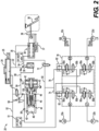
- Fig. 2 shows a schematic diagram of a BbW system 20 for controlling operation of a plurality of wheel brakes 22a, 22b, 22c, 22d in a vehicle.
- Each of the wheel brakes 22a, 22b, 22c, 22d may include a corresponding one of the brake actuators 13.
- the wheel brakes 22a, 22b, 22c, 22d may also be called foundation brakes to distinguish from other braking systems, such as electric regenerative braking.
- the BbW system 20 includes a fluid reservoir 24 holding a hydraulic fluid and supplying the hydraulic fluid to a single-circuit master cylinder 30 having a single-circuit configuration, and which may be referred to as a master cylinder (MC) 30.
- a fluid level sensor 25 such as a float switch, monitors a level of the hydraulic fluid in the fluid reservoir 24.
- a brake pedal 36 is coupled to press a brake linkage 38 which, in turn, actuates the master cylinder (MC) 30 to pump fluid therethrough from an intake fluid passage 32 and to pressurize a master cylinder (MC) fluid passageway 34.
- a travel sensor 37 monitors a position of the brake pedal 36.
- a first pressure sensor 33 monitors the pressure in the MC fluid passageway 34.
- a PFE 39 is fluidly coupled to the MC fluid passageway 34 to selectively provide a natural feeling of brake operation, particularly when the master cylinder 30 is decoupled from operating the wheel brakes 22a, 22b, 22c, 22d.
- the PFE 39 includes a PFE piston dividing the PFE 39 into an upper chamber and a lower chamber, and a spring biasing the PFE piston into the upper chamber.
- the upper chamber of the PFE 39 is fluidly coupled to the MC fluid passageway 34.
- a PSU assembly 40 includes an electric motor 42 and a PSU pump 44 to supply the hydraulic fluid from the fluid reservoir 24 to a PSU fluid passageway 50.
- the PSU assembly 40 may draw fluid from a return fluid passageway 52 that is connected to the fluid reservoir 24 and which is maintained at or near ambient atmospheric pressure.
- a second pressure sensor 51 monitors the pressure in the PSU fluid passageway 50.
- a rotor angle sensor 43 may be coupled to the electric motor 42 to determine a position of the rotor in the motor, and thus a position of the PSU pump 44.
- the PSU pump 44 includes a PSU piston 45 that separates a first chamber 46 from a second chamber 48.
- the PSU pump 44 includes the electric motor 42 coupled to a ball screw actuator 118, which converts rotary motion to linear motion for moving the PSU piston 45.
- the first chamber 46 of the PSU assembly 40 is directly connected to the PSU fluid passageway 50.
- the second chamber 48 of the PSU assembly 40 is directly connected to a replenishing fluid passageway 54.
- a first check valve 56 allows fluid flow from the return fluid passageway 52 into the replenishing fluid passageway 54, while blocking fluid flow in an opposite direction.
- a second check valve 58 which may also be called a PSU replenish check valve (PRCV), allows fluid flow from the replenishing fluid passageway 54 into the PSU fluid passageway 50 while blocking fluid flow in an opposite direction.
- PRCV PSU replenish check valve
- a PSU reservoir isolation valve (PRIV) 62 which may be a normally-closed solenoid valve, selectively controls fluid flow between the return fluid passageway 52 and an intermediate fluid passageway 64.
- a third check valve 66 is connected between the intermediate fluid passageway 64 and the replenishing fluid passageway 54 and is configured to allow fluid flow from the replenishing fluid passageway 54 to flow into the intermediate fluid passageway 64 while blocking fluid flow in an opposite direction.
- a master cylinder isolation valve (MCIV) 72 which may be a normally-open solenoid valve, selectively controls fluid flow between the MC fluid passageway 34 and the PSU fluid passageway 50.
- the PSU fluid passageway 50 splits fluid supply into a first brake circuit 74 and a second brake circuit 76.
- a control valve manifold 78 fluidly connects the two brake circuits 74, 76 to the corresponding wheel brakes 22a, 22b, 22c, 22d.
- the control valve manifold 78 includes an apply valve 80a and a release valve 80b corresponding to each of the wheel brakes 22a, 22b, 22c, 22d to selectively control fluid flow between the corresponding one of the of the wheel brakes 22a, 22b, 22c, 22d and an associated one of the two brake circuits 74, 76.
- the apply valves 80a and the release valves 68b may collectively be called antilock brake system (ABS) valves for their use in such an ABS.
- ABS antilock brake system
- the apply valves 80a and the release valves 80b may be used for other functions, such as for traction control and/or for torque vectoring.
- a bi-directional check valve 82 is disposed in each of the two brake circuits 74, 76 between the PSU fluid passageway 50 and the control valve manifold 78.
- the bi-directional check valve 82 may allow fluid flow in either direction, but only when a differential pressure thereacross is above some threshold value.
- the bi-directional check valve 82 may limit an amount of fluid lost in case of a leak in the system, such as a leak in a brake line supplying any of the wheel brakes 22a, 22b, 22c, 22d.
- the PSU pump 44 includes the PSU piston 45 that is pushed and/or pulled by the ball screw actuator 118, which converts rotary motion to linear motion for moving the PSU piston 45.
- the ball screw actuator 118 includes a spindle 122 and an actuator nut assembly 120, 124.
- the actuator nut assembly 120, 124 includes a nut 120 and a plurality of ball bearings 124 disposed between the spindle 122 and the actuator nut 120.
- the actuator nut 120 is attached to the PSU piston 45.
- the electric motor 42 is configured to rotate the spindle 122, which is threaded and configured to move the actuator nut 120 in a linear path, thereby causing the PSU piston 45 to translate through the piston bore 102 in either of two directions, toward or away from the electric motor 42.
- the ball screw actuator therefore, causes the PSU piston 45 to be translated linearly through the piston bore 102 in response to the electric motor 42 rotating the spindle 122.
- the actuator nut 120 and the plurality of ball bearings 124 are each disposed within the piston bore 102 and submerged in hydraulic fluid.
- the PSU piston 45 has a cup shape, and the actuator nut 120 and the plurality of ball bearings 124 are each disposed within the cup shape of the PSU piston.
- the actuator nut 120 and the plurality of ball bearings 124 are each disposed within the second chamber 48.
- the PSU assembly 40 may have a different configuration, for example with the actuator nut 120 and the plurality of ball bearings 124 being located in the first chamber 46.
- a ring seal 128 is disposed between the spindle 122 and the partition 106, providing a fluid-tight seal between the piston bore 102 from the rear chamber 104, while allowing the spindle 122 to rotate.
- the ring seal 128 may include a lip seal. However, many types of seals may be used. Note that this enables fluid to be trapped on the back side of PSU piston 45 to have the back side of piston seal 140 to be exposed to brake pressure from replenishing fluid passageway 54 and counterbalance the brake pressure exposed to the front side of piston seal 140 from PSU passageway 50, thus creating pressure balance.
- the PSU piston 45 is disposed within the piston bore 102 and configured to move linearly therethrough in response to being pushed and/or pulled by the actuator nut 120.
- the piston bore 102 extends between the partition 106 and a terminal end 130.
- the piston bore 102 defines the first chamber 46, which extends from the PSU piston 45 to the terminal end 130.
- the piston bore 102 also defines the second chamber 48, which extends from the partition 106 to the PSU piston 45.
- a first PSU port 132 provides fluid communication between the first chamber 46 and external fluid circuits.
- the first PSU port 132 may be fluidly coupled to the PSU fluid passageway 50 for supplying the fluid thereto.
- a second PSU port 134 provides fluid communication between the second chamber 48 and external fluid circuits.
- the second PSU port 134 may be fluidly coupled to the replenishing fluid passageway 54 for conveying fluid between the second chamber 48 and the replenishing fluid passageway 54.
- the PSU piston 45 includes a piston seal 140, such as a lip seal that prevents fluid from leaking by the PSU piston 45 between the first chamber 46 and the second chamber 48.
- the PSU piston 45 includes a first anti-rotation structure 142, such as one or more protrusions that engage corresponding second anti-rotation structures 144 in the piston bore 102.
- the second anti-rotation structure 144 may include one or more linear troughs or keyways configured to receive the corresponding first anti-rotation structure 142. Together, the anti-rotation structures 142, 144 may prevent the PSU piston 45 from rotating, while allowing the PSU piston 45 to translate linearly through the piston bore 102.
- Figs. 5A - 5C show cut-away diagrams of three different PSUs.
- Fig. 5A shows a first PSU assembly 150 with a double-acting configuration includes a pressure-balanced design with fluid on both sides of the piston, and with an actuator rod coupling a ball screw type linear actuator to the piston.
- Fig. 5B shows a second PSU assembly 152 in accordance with the present disclosure.
- the second PSU assembly 152 may be similar or identical to the PSU assembly 40 of the present disclosure, but with a lip seal in place of the ring seal 128.
- Fig. 5C shows a third PSU assembly 154 having a conventional design, with fluid on only one side of the piston.
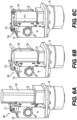
- Fig. 6A shows a first one-box brake-by-wire device 160 that includes the first PSU assembly 150 of Fig. 5A .
- the first one-box brake-by-wire device 160 includes a first hydraulic control unit (HCU) body 170 having a first top surface 171 opposite from the electric motor 42, with the first PSU assembly 150 extending along a side face of the first HCU body 170 and substantially beyond and above the first top surface 171.
- Fig. 6B shows a second one-box brake-by-wire device 162 that includes the second PSU assembly 152 of Fig. 5B .
- HCU hydraulic control unit
- the second one-box brake-by-wire device 162 includes a second hydraulic control unit (HCU) body 172 having a second top surface 173 opposite from the electric motor 42, with the second PSU assembly 152 extending along a side face of the second HCU body 172 and protruding slightly beyond and above the second top surface 173, but to a lesser extent than the first PSU assembly 150 extends above the first top surface 171 of the first PSU assembly 150.
- Fig. 6C shows a third one-box brake-by-wire device 164 that includes the third PSU assembly 154 of Fig. 5C .
- the third one-box brake-by-wire device 164 includes a third HCU body 174 having a third top surface 175 opposite from the electric motor 42, with the third PSU assembly 154 extending along a side face of the third HCU body 174 ending flush with the third top surface 175.
- the difference between the PSUs shown on Figs. 5A and 5B show an example of the size and mass savings that may result from the elimination of the separate actuator, and providing the ball screw to be flooded with brake fluid instead of being dry.
- Fig. 7 shows a cross-sectional view of a fourth one-box brake-by-wire device 166. It still maintains a pressure balanced PSU piston 45. The back side of piston seal 140 is exposed to brake pressure from replenishing fluid passageway 54 while the front side of piston seal 140 is exposed to pressure from PSU passageway 50 enabling pressure balance.
- This fourth PSU assembly 156 is shown in a transverse motor configuration, with the motor 42 oriented such that the motor shaft is horizontal and transverse to a master cylinder bore (not shown) in a fourth HCU body 176. The fourth PSU assembly 156 may have a similar or identical configuration to the second PSU assembly 152 of Fig. 5B .
- the fourth one-box brake-by-wire device 166 having a transverse motor configuration may provide for a space savings and eliminate costly motor-to-ECU connectors.
- This design may include a standard brushless motor driving a planetary geartrain to minimize overall cost, maximize motor efficiency, and minimize motor current draw. Reduced motor current draw can provide for an additional cost savings in electronics for powering the motor.
- Fig. 8 shows a schematic diagram of the 10-valve brake-by-wire system of Fig. 2 , with additional features, in accordance with an aspect of the present disclosure.
- Fig. 8 includes a one-box, 10-valve BbW device 220, as an integrated assembly.
- the 10-valve system is so-named because of its inclusion of ten actuated valves including the PRIV 62, the MCIV 72, plus the eight solenoid valves in the control valve manifold 78.
- Fig. 8 also shows the 10-valve BbW device 220 that includes an electronic control unit (ECU) 90, with electrical connections for monitoring the various sensors and for controlling the various actuators, such as the electric motor 42 of the PSU assembly 40, and the solenoid valves.
- ECU electronice control unit
- the ECU 90 is also connected to one or more external controllers 92 of a vehicle via a communications network, such as Controller Area Network (CAN bus).
- the ECU 90 is also configured to control actuation and/or other functions of one or more electric parking brake actuators EPB.
- the ECU 90 is also configured to receive a parking brake command from a parking brake switch 93 via the communications network. Alternatively or additionally, the parking brake switch 93 may be hardwired to the ECU 90.
- the 10-valve design shown in Fig. 8 includes the PSU assembly 40 and the master cylinder 30.
- the MCIV 72 When in brake-by-wire mode and the driver applies the brake pedal, the MCIV 72 is closed, and the PRIV 62 is opened. Fluid is directed from the master cylinder 30 to the PFE 39 to simulate normal brake pedal force and travel. That same travel information is sent to the ECU 90 which subsequently applies the appropriate current to the PSU motor to rotate the ball screw and mechanically displace the PSU piston 45. This causes the fluid to travel through the dual check valves 82, through the ABS apply valves 80a, and finally reaching the wheel brakes to apply pressure and slow the vehicle.
- Fig. 9 shows a schematic diagram of a 11-valve brake-by-wire system, in accordance with an aspect of the present disclosure.
- the 11-valve brake-by-wire system may be similar or identical to the 10-valve system of Fig. 8 , with a few changes discussed herein.
- the 11-valve brake-by-wire system includes a PFE isolation valve (PFIV) 212, which may be a normally-open solenoid valve, selectively coupling the intermediate fluid passageway 64 and the displacement fluid passageway 68.
- PFIV PFE isolation valve
- the 11-valve brake-by-wire system also does not include several check valves present in the 10-valve system of FIG 8 , such as the third check valve 66, the fourth check valve 69, and the fifth check valve 70.
- Fig. 9 includes a one-box, 11-valve BbW device 320, as an integrated assembly.
- the 11-valve system is so-named because of its inclusion of eleven actuated valves including the PRIV 62, the MCIV 72, the PFIV 212, plus the eight solenoid valves in the control valve manifold 78.
- the 11-valve design shown in Fig. 9 includes the PSU assembly 40 and the master cylinder 30.
- the MCIV 72 When in brake-by-wire mode and the driver applies the brake pedal, the MCIV 72 is closed, and the PRIV 62 is opened. Fluid from the master cylinder 30 is directed to the PFE 39 to simulate normal brake pedal force and travel. That same travel information is sent to the ECU 90, which subsequently applies the appropriate current to the PSU motor 42 to rotate the ball screw and mechanically displace the PSU piston 45. This causes the fluid to travel through the dual check valves 82, through the ABS apply valves 80a, and finally reaching the wheel brakes to apply pressure and slow the vehicle.
- Fig. 10 shows a schematic diagram of a 12-valve brake-by-wire system, in accordance with an aspect of the present disclosure.
- the 12-valve brake-by-wire system may be similar or identical to the 11-valve system of Fig. 9 , with a few changes discussed herein.
- the 12-valve brake-by-wire system includes a brake circuit isolation valve (BCIV) 312, which may be a normally-open solenoid valve, selectively coupling the PSU fluid passageway 50 and the second brake circuit 76.
- BCIV brake circuit isolation valve
- Fig. 10 includes a one-box, 12-valve BbW device 420, as an integrated assembly.
- the 12-valve system is so-named because of its inclusion of twelve actuated valves including the PRIV 62, the MCIV 72, the PFIV 212, brake circuit isolation valve 312, plus the eight solenoid valves in the control valve manifold 78.
- the one-box, 12-valve BbW device 420 of Fig. 10 also includes a Brake Circuit Balance Orifice (BCBO) 314 configured to restrict fluid flow through only the first brake circuit 74 to two of the wheel brakes 22a, 22b, 22c, 22d.
- the BCBO 314 is connected in line with the supply-side check valve of the dual check valves 82 to regulate fluid flow from the PSU fluid passageway 50 to the corresponding ones of the wheel brakes 22a, 22b, 22c, 22d.
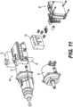
- Fig. 11 shows a fifth one-box brake-by-wire device 165 having an axial configuration, with the electric motor 42 and the piston bore 102 of the PSU assembly 40 axially aligned with the master cylinder 30, and with a fifth HCU 178 located aside the axial arrangement of the PSU and the master cylinder 30.
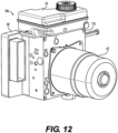
- Fig. 12 shows the fourth one-box brake-by-wire device 166 of Fig. 7 in an assembled condition with the fluid reservoir 24 attached to the top, and the ECU 90 attached on a side face of the fourth HCU body 176 opposite from the electric motor 42.
- Fig. 13 shows a sixth one-box brake-by-wire device 168 with a motor-up configuration.
- Fig. 14 shows the third one-box brake-by-wire device 164 of Fig. 6C with a motor-down configuration and in an assembled condition with the fluid reservoir 24 attached to the top, and the ECU 90 attached on a side face of the third HCU body 174 opposite from the electric motor 42.
- the third one-box brake-by-wire device 164 includes the fluid reservoir 24 mounted on the top surface of the third HCU body 174 and the electric motor 42 of the PSU assembly 40 is mounted to the bottom surface of the third HCU body 174, opposite from the fluid reservoir 24. Also, the third PSU assembly 154, which includes the PSU housing 100 defining the piston bore 102, does not extend beyond the top surface of the third HCU body 174.
- the one-box BbW devices 220, 320, 420 of the present disclosure may be packaged in any configuration.
- any of the one-box BbW devices 220, 320, 420 may have an axial configuration, with the PSU assembly 40 axially aligned with the master cylinder 30, as shown in Fig. 11 .
- any of the one-box BbW devices 220, 320, 420 may have a transverse motor configuration, with the electric motor 42 having a motor shaft that extends horizontally and transverse to the master cylinder 30, as shown in Fig. 12 .
- any of the one-box BbW devices 220, 320, 420 may have a motor-up configuration, with the electric motor 42 located above the master cylinder 30, as shown in Fig. 13 . Additionally or alternatively, any of the one-box BbW devices 220, 320, 420 may have a motor-down configuration, as shown in Fig. 14 .
- the first brake system may include: a brake pedal for actuating a brake master cylinder having a housing and a single piston and which defines a single pressure chamber which is subsequently connected to the wheel brakes 22a, 22b, 22c, 22d, wherein an actuating force exerted by the brake pedal is exerted on the single piston upon actuation of the brake system by the vehicle driver and the piston is positioned in a starting position by a return spring when the brake pedal is not actuated;
- the first brake system may further include: a pressure medium reservoir for a pressure medium which is exposed to atmospheric pressure and has a reservoir chamber associated with the pressure chamber.
- the first brake system may further include: a travel detection device which detects the actuation travel of the brake pedal or at least the piston connected to the brake pedal; a pedal feel emulator which conveys a desired haptic brake pedal feel to the vehicle driver in the brake-by-wire mode, being connected hydraulically directly to the master cylinder pressure chamber;
- the first brake system may further include: an electrically controllable pressure supply unit which delivers a brake system pressure and consists of a floating piston sealed to the main housing bore and containing at least one anti-rotation feature that connects with at least one groove in the main housing bore which prevents piston rotation but permits piston translation.
- an electrically controllable pressure supply unit which delivers a brake system pressure and consists of a floating piston sealed to the main housing bore and containing at least one anti-rotation feature that connects with at least one groove in the main housing bore which prevents piston rotation but permits piston translation.
- the first brake system may further include: the pressure supply unit piston displaced by an independently actuated ball screw nut of a ball screw assembly on one end to supply brake system pressure whereas the ball screw spindle of said ball screw assembly is permanently attached to the inner race of a ball bearing assembly whose outer race is permanently attached to a stepped bore in the main housing and whose inner race permits rotation but prevents translation of said ball screw spindle.
- the first brake system may further include: said ball screw assembly spindle is also sealed to the main housing in a corresponding bore containing a radial lip seal thus permitting brake fluid entrance to the ball screw assembly nut and roller balls, but preventing brake fluid entrance to the area containing the bearing inner race,
- the first brake system may further include: said ball bearing inner race containing at least one pin on which is rotatably attached a planet gear of a planetary gearset assembly whose outer ring gear is permanently attached to a stepped bore of the main bore and whose sun gear is permanently attached to the output shaft of an electric motor.
- the motor may be a brushless motor.
- the first brake system may further include: a normally open valve for isolating the master cylinder from the brake circuit located between the master cylinder outlet port and the wheel brakes.
- the first brake system may further include: a normally closed valve for isolating the motor side of the electrically controllable pressure source to the reservoir.
- the first brake system may further include: a series of check valves that allow flow from the pedal feel emulator to the normally closed valve above, but prohibit flow in the opposite direction.
- a second brake system for motor vehicles may include the 11-valve brake-by-wire system of the present disclosure.
- the second brake system can be activated by a vehicle driver in a normal brake-by-wire operating mode, via electrical actuation.
- the second brake system can also be operated by the same driver in at least one fallback operating mode in which one or more of the wheel brakes 22a, 22b, 22c, 22d is directly operable in response to application of the brake pedal 36, and without any electrical power.
- the second brake system may include: a brake pedal for actuating a brake master cylinder having a housing and a single piston and which defines a single pressure chamber which is subsequently connected to the wheel brakes, wherein an actuating force exerted by the brake pedal is exerted on the single piston upon actuation of the brake system by the vehicle driver and the piston is positioned in a starting position by a return spring when the brake pedal is not actuated.
- the second brake system may also include: a pressure medium reservoir for a pressure medium which is exposed to atmospheric pressure and has a reservoir chamber associated with the pressure chamber.
- the second brake system may also include: a travel detection device which detects the actuation travel of the brake pedal or at least the piston connected to the brake pedal.
- the second brake system may also include: a pedal feel emulator which conveys a desired haptic brake pedal feel to the vehicle driver in the brake-by-wire mode, being connected hydraulically directly to the master cylinder pressure chamber.
- the second brake system may also include: an electrically controllable pressure supply unit which delivers a brake system pressure and consists of a floating piston sealed to the main housing bore and containing at least one anti-rotation feature that connects with at least one groove in the main housing bore which prevents piston rotation but permits piston translation.
- an electrically controllable pressure supply unit which delivers a brake system pressure and consists of a floating piston sealed to the main housing bore and containing at least one anti-rotation feature that connects with at least one groove in the main housing bore which prevents piston rotation but permits piston translation.
- the second brake system may also include: said ball screw assembly spindle is also sealed to the main housing in a corresponding bore containing a radial lip seal thus permitting brake fluid entrance to the ball screw assembly nut and roller balls, but preventing brake fluid entrance to the area containing the bearing inner race.
- the second brake system may also include: said ball bearing inner race containing at least one pin on which is rotatably attached a planet gear of a planetary gearset assembly whose outer ring gear is permanently attached to a stepped bore of the main bore and whose sun gear is permanently attached to the output shaft of an electric motor.
- the motor may be a brushless motor.
- the second brake system may also include: a normally open valve for isolating the master cylinder from the brake circuit located between the master cylinder outlet port and the wheel brakes.
- the second brake system may also include: a normally closed valve for isolating the motor side of the electrically controllable pressure source to the reservoir.
- the second brake system may also include: a forward flow and reverse flow check valve in parallel to each other and located between the pressure supply unit and two of the wheel brakes with a second forward flow and reverse flow check valve in parallel to each other and located between the pressure supply unit and the remaining pair of wheel brakes.
- a third brake system for motor vehicles may include the 12-valve brake-by-wire system of the present disclosure.
- the third brake system can be activated by a vehicle driver in a normal brake-by-wire operating mode, via electrical actuation.
- the third brake system can also be operated by the same driver in at least one fallback operating mode in which only operation of the brake system by the vehicle driver is possible.
- the third brake system may also include: a pedal feel emulator which conveys a desired haptic brake pedal feel to the vehicle driver in the brake-by-wire mode, being connected hydraulically directly to the master cylinder pressure chamber.
Landscapes
- Engineering & Computer Science (AREA)
- Mechanical Engineering (AREA)
- Transportation (AREA)
- Physics & Mathematics (AREA)
- Fluid Mechanics (AREA)
- General Engineering & Computer Science (AREA)
- Regulating Braking Force (AREA)
- Transmission Of Braking Force In Braking Systems (AREA)
- Braking Systems And Boosters (AREA)
Abstract
Description
- The present disclosure relates generally to brake systems for vehicles, such as automobiles. More specifically, the present disclosure relates to a brake-by-wire system with a pressure supply unit (PSU) having a pressure-balanced piston.
- As electric and hybrid vehicles continue to proliferate in markets around the world, it is well understood that significant lengthening of battery life can be obtained by utilizing the motor-generator output capabilities of that device during braking. However, the input torque in the generator mode used to recharge batteries is not consistent with driver input function of pedal force/travel verses vehicle deceleration. In order to achieve that complex function, the hydraulic brakes of the vehicle must supply the difference between generator braking torque and driver requested braking torque.
- The engineering world has understood this requirement for a number of years commonly known as regenerative brake blending. A most efficient way to achieve this is to use a "brake-by-wire" technique. To accomplish this, the brake pedal in effect becomes a joy stick, so it must be connected to a travel and/or force sensor in order to send a signal to the system ECU that will interpret this as driver's intent of a desired vehicle deceleration. In addition, the brake pedal "feel" must be simulated by the appropriate force-travel relationship and must also have the ability to be isolated from directly applying the master cylinder to the wheel brakes.
- Brake-by-wire systems typically include a pressure supply unit (PSU) to provide a supply of pressurized fluid for actuating the wheel brakes.
- The present disclosure provides an electro-hydraulic brake system. The electro-hydraulic brake system comprises a single-circuit master cylinder (MC) fluidly coupled to a first MC fluid passageway and configured to supply fluid into the first MC fluid passageway in response to pressing force on a brake pedal coupled thereto. The electro-hydraulic brake system also comprises a pressure supply unit (PSU) assembly including an electric motor coupled to a ball screw actuator, a PSU housing defining a piston bore having a terminal end opposite the electric motor, and a PSU piston disposed within the piston bore and movable by the ball screw actuator through the piston bore and dividing the piston bore into a first chamber and a second chamber, with each of the first chamber and the second chamber containing a hydraulic fluid. The ball screw actuator includes an actuator nut assembly having a plurality of ball bearings each disposed within the piston bore and submerged in the hydraulic fluid.
- The present invention also provides a pressure supply unit (PSU) assembly for an electro-hydraulic brake system. The PSU assembly comprises: an electric motor; a ball screw actuator including a spindle coupled to the electric motor and configured to transfer rotary motion to linear motion; a PSU housing coupled to the electric motor and defining a piston bore having a terminal end opposite the electric motor; and a PSU piston disposed within the piston bore and translatable by the ball screw actuator through the piston bore and dividing the piston bore into a first chamber and a second chamber, with each of the first chamber and the second chamber containing a hydraulic fluid. The ball screw actuator includes an actuator nut assembly having a plurality of ball bearings each disposed within the second chamber of the piston bore and submerged in the hydraulic fluid.
- Further details, features and advantages of designs of the invention result from the following description of embodiment examples in reference to the associated drawings.
-
Fig. 1 shows a schematic block diagram of a brake-by-wire system in a vehicle; -
Fig. 2 shows a schematic diagram of a brake-by-wire system of the present disclosure; -
Fig. 3 shows a cut-away diagram of a pressure supply unit (PSU), in accordance with an aspect of the present disclosure; -
Fig. 4 shows a cut-away diagram of the PSU of the present disclosure with an alternative PSU for size reference; -
Figs. 5A - 5C show cut-away diagrams of three different PSUs, in accordance with an aspect of the present disclosure; -
Figs. 6A-6C each show a perspective views of a one-box brake-by-wire device, each including a corresponding one of the three different PSUs shown inFigs. 5A-5C ; -
Fig. 7 shows a cross-sectional view of a one-box brake-by-wire device including the PSU of the present disclosure in a transverse motor configuration; -
Fig. 8 shows a schematic diagram of the 10-valve brake-by-wire system ofFig. 2 , with additional features, in accordance with an aspect of the present disclosure; -
Fig. 9 shows a schematic diagram of a 11-valve brake-by-wire system, in accordance with an aspect of the present disclosure; -
Fig. 10 shows a schematic diagram of a 12-valve brake-by-wire system, in accordance with an aspect of the present disclosure; -
Fig. 11 shows a one-box brake-by-wire device having an axial configuration, with the PSU axially aligned with the master cylinder; -
Fig. 12 shows a one-box brake-by-wire device with a transverse motor configuration; -
Fig. 13 shows a one-box brake-by-wire device with a motor-up configuration; and -
Fig. 14 shows a one-box brake-by-wire device with a motor-down configuration. - Referring to the drawings, the present invention will be described in detail in view of following embodiments.
-
Fig. 1 shows a schematic block diagram of a brake-by-wire (BbW)system 10 in a vehicle, such as an automobile, and which includes a plurality ofwheel brakes master cylinder 30 either directly applies one or more of thewheel brakes wheel brakes system 10 as an input signal to a brake electronic control unit (ECU) 90. It in turn sends the appropriate signal to a pressure supply unit (PSU)assembly 40. ThePSU assembly 40 may include a high efficiency brushless motor and ball screw assembly displacing one or more PSU pistons, which can be thought of as an electric master cylinder. Themaster cylinder 30 and/or thePSU assembly 40 may be coupled to thewheel brakes control valves 15, which may include an apply valve and a release valve (not shown) for each of thewheel brakes - The brake pedal inputs define driver intent which determines how fast and how hard the brakes are applied with the goal to replicated the feel of a conventional vacuum booster brake system. The
brake ECU 90 may also send a signal to a drive control unit (DCU) 18, which may also be called a powertrain control module (PCM) 18 to slow the vehicle using one or more electric motors in a regenerative mode. -
Fig. 2 shows a schematic diagram of a BbW system 20 for controlling operation of a plurality ofwheel brakes wheel brakes wheel brakes - The BbW system 20 includes a
fluid reservoir 24 holding a hydraulic fluid and supplying the hydraulic fluid to a single-circuit master cylinder 30 having a single-circuit configuration, and which may be referred to as a master cylinder (MC) 30. Afluid level sensor 25, such as a float switch, monitors a level of the hydraulic fluid in thefluid reservoir 24. Abrake pedal 36 is coupled to press abrake linkage 38 which, in turn, actuates the master cylinder (MC) 30 to pump fluid therethrough from anintake fluid passage 32 and to pressurize a master cylinder (MC)fluid passageway 34. Atravel sensor 37 monitors a position of thebrake pedal 36. A first pressure sensor 33 monitors the pressure in theMC fluid passageway 34. - A
PFE 39 is fluidly coupled to theMC fluid passageway 34 to selectively provide a natural feeling of brake operation, particularly when themaster cylinder 30 is decoupled from operating thewheel brakes PFE 39 includes a PFE piston dividing thePFE 39 into an upper chamber and a lower chamber, and a spring biasing the PFE piston into the upper chamber. The upper chamber of thePFE 39 is fluidly coupled to theMC fluid passageway 34. - A
PSU assembly 40 includes anelectric motor 42 and aPSU pump 44 to supply the hydraulic fluid from thefluid reservoir 24 to aPSU fluid passageway 50. ThePSU assembly 40 may draw fluid from areturn fluid passageway 52 that is connected to thefluid reservoir 24 and which is maintained at or near ambient atmospheric pressure. Asecond pressure sensor 51 monitors the pressure in thePSU fluid passageway 50. Arotor angle sensor 43 may be coupled to theelectric motor 42 to determine a position of the rotor in the motor, and thus a position of thePSU pump 44. ThePSU pump 44 includes aPSU piston 45 that separates afirst chamber 46 from asecond chamber 48. ThePSU pump 44 includes theelectric motor 42 coupled to aball screw actuator 118, which converts rotary motion to linear motion for moving thePSU piston 45. - The
first chamber 46 of thePSU assembly 40 is directly connected to thePSU fluid passageway 50. In response to thePSU piston 45 moving away from theelectric motor 42, fluid is pressed out of thefirst chamber 46 and into thePSU fluid passageway 50. Thesecond chamber 48 of thePSU assembly 40 is directly connected to a replenishingfluid passageway 54. Afirst check valve 56 allows fluid flow from thereturn fluid passageway 52 into the replenishingfluid passageway 54, while blocking fluid flow in an opposite direction. Asecond check valve 58, which may also be called a PSU replenish check valve (PRCV), allows fluid flow from the replenishingfluid passageway 54 into thePSU fluid passageway 50 while blocking fluid flow in an opposite direction. - A PSU reservoir isolation valve (PRIV) 62, which may be a normally-closed solenoid valve, selectively controls fluid flow between the
return fluid passageway 52 and anintermediate fluid passageway 64. Athird check valve 66 is connected between theintermediate fluid passageway 64 and the replenishingfluid passageway 54 and is configured to allow fluid flow from the replenishingfluid passageway 54 to flow into theintermediate fluid passageway 64 while blocking fluid flow in an opposite direction. - A
displacement fluid passageway 68 is connected to the lower chamber of thePFE 39 for transmitting fluid therefrom in response to the PFE piston moving from application of thebrake pedal 36. Afourth check valve 69 is connected between thedisplacement fluid passageway 68 and theintake fluid passage 32 and is configured to allow fluid flow from theintake fluid passage 32 to flow into thedisplacement fluid passageway 68 while blocking fluid flow in an opposite direction. Afifth check valve 70 is connected between thedisplacement fluid passageway 68 andintermediate fluid passageway 64 and is configured to allow fluid flow from thedisplacement fluid passageway 68 to flow into theintermediate fluid passageway 64 while blocking fluid flow in an opposite direction. - A master cylinder isolation valve (MCIV) 72 which may be a normally-open solenoid valve, selectively controls fluid flow between the
MC fluid passageway 34 and thePSU fluid passageway 50. ThePSU fluid passageway 50 splits fluid supply into afirst brake circuit 74 and asecond brake circuit 76. - A
control valve manifold 78 fluidly connects the twobrake circuits corresponding wheel brakes control valve manifold 78 includes an applyvalve 80a and arelease valve 80b corresponding to each of thewheel brakes wheel brakes brake circuits valves 80a and the release valves 68b may collectively be called antilock brake system (ABS) valves for their use in such an ABS. However, the applyvalves 80a and therelease valves 80b may be used for other functions, such as for traction control and/or for torque vectoring. - In some embodiments, and as shown in
Fig. 2 , abi-directional check valve 82 is disposed in each of the twobrake circuits PSU fluid passageway 50 and thecontrol valve manifold 78. Thebi-directional check valve 82 may allow fluid flow in either direction, but only when a differential pressure thereacross is above some threshold value. Thebi-directional check valve 82 may limit an amount of fluid lost in case of a leak in the system, such as a leak in a brake line supplying any of thewheel brakes - When the driver applies the brakes the
MCIV 72 is closed, and thePRIV 62 is opened. Fluid from themaster cylinder 30 is directed to thePFE 39 to simulate normal brake pedal force and travel. That same travel information may be sent to an electronic control unit (ECU) 90, which subsequently applies the appropriate current to thePSU motor 42 to rotate the ball screw and mechanically displace thePSU piston 45. This causes the fluid to travel through thedual check valves 82, through the ABS applyvalves 80a, and finally reaching thewheel brakes -
Fig. 3 shows a cut-away diagram of thePSU assembly 40 of the present disclosure. ThePSU assembly 40 includes theelectric motor 42 configured to operate thePSU pump 44 to discharge brake fluid to thePSU fluid passageway 50. - The
PSU assembly 40 includes aPSU housing 100 defining apiston bore 102. ThePSU housing 100 also defines arear chamber 104, which contains theelectric motor 42. Apartition 106 separates the piston bore 102 from therear chamber 104. Thepartition 106 allows therear chamber 104 to be maintained dry, while the piston bore 102 contains brake fluid. Theelectric motor 42 includes amotor shaft 110 coupled to arotor 112, which is acted upon by electrical current in astator 114.Shaft bearings 116 may support themotor shaft 110 on either side of therotor 112. - The
PSU pump 44 includes thePSU piston 45 that is pushed and/or pulled by theball screw actuator 118, which converts rotary motion to linear motion for moving thePSU piston 45. Theball screw actuator 118 includes aspindle 122 and anactuator nut assembly actuator nut assembly nut 120 and a plurality ofball bearings 124 disposed between thespindle 122 and theactuator nut 120. Theactuator nut 120 is attached to thePSU piston 45. Theelectric motor 42 is configured to rotate thespindle 122, which is threaded and configured to move theactuator nut 120 in a linear path, thereby causing thePSU piston 45 to translate through the piston bore 102 in either of two directions, toward or away from theelectric motor 42. The ball screw actuator, therefore, causes thePSU piston 45 to be translated linearly through the piston bore 102 in response to theelectric motor 42 rotating thespindle 122. Theactuator nut 120 and the plurality ofball bearings 124 are each disposed within the piston bore 102 and submerged in hydraulic fluid. - In some embodiments, and as shown in
Fig. 3 , thePSU piston 45 has a cup shape, and theactuator nut 120 and the plurality ofball bearings 124 are each disposed within the cup shape of the PSU piston. - In some embodiments, and as shown in
Fig. 3 , theactuator nut 120 and the plurality ofball bearings 124 are each disposed within thesecond chamber 48. However, thePSU assembly 40 may have a different configuration, for example with theactuator nut 120 and the plurality ofball bearings 124 being located in thefirst chamber 46. - In some embodiments, one or
more ball bearings 124 may be disposed between thespindle 122 and theactuator nut 120, providing a ball-screw interface. A gear set 126, which may include one or more planetary reduction gears, mechanically couples themotor shaft 110 of theelectric motor 42 and thespindle 122, reducing the speed and increasing torque applied to thespindle 122. The gear set 126 is driven by theelectric motor 42 and is configured to drive thespindle 122 at a speed that is slower than a speed of themotor shaft 110 ofelectric motor 42. - A
ring seal 128 is disposed between thespindle 122 and thepartition 106, providing a fluid-tight seal between the piston bore 102 from therear chamber 104, while allowing thespindle 122 to rotate. Thering seal 128 may include a lip seal. However, many types of seals may be used. Note that this enables fluid to be trapped on the back side ofPSU piston 45 to have the back side ofpiston seal 140 to be exposed to brake pressure from replenishingfluid passageway 54 and counterbalance the brake pressure exposed to the front side ofpiston seal 140 fromPSU passageway 50, thus creating pressure balance. - The
PSU piston 45 is disposed within the piston bore 102 and configured to move linearly therethrough in response to being pushed and/or pulled by theactuator nut 120. The piston bore 102 extends between thepartition 106 and aterminal end 130. The piston bore 102 defines thefirst chamber 46, which extends from thePSU piston 45 to theterminal end 130. The piston bore 102 also defines thesecond chamber 48, which extends from thepartition 106 to thePSU piston 45. Afirst PSU port 132 provides fluid communication between thefirst chamber 46 and external fluid circuits. Thefirst PSU port 132 may be fluidly coupled to thePSU fluid passageway 50 for supplying the fluid thereto. Asecond PSU port 134 provides fluid communication between thesecond chamber 48 and external fluid circuits. Thesecond PSU port 134 may be fluidly coupled to the replenishingfluid passageway 54 for conveying fluid between thesecond chamber 48 and the replenishingfluid passageway 54. - In some embodiments, and as shown in
Fig. 3 , thePSU piston 45 includes apiston seal 140, such as a lip seal that prevents fluid from leaking by thePSU piston 45 between thefirst chamber 46 and thesecond chamber 48. In some embodiments, and as also shown inFig. 3 , thePSU piston 45 includes a firstanti-rotation structure 142, such as one or more protrusions that engage corresponding secondanti-rotation structures 144 in the piston bore 102. For example, the secondanti-rotation structure 144 may include one or more linear troughs or keyways configured to receive the corresponding firstanti-rotation structure 142. Together, theanti-rotation structures PSU piston 45 from rotating, while allowing thePSU piston 45 to translate linearly through the piston bore 102. - According to an aspect of the disclosure, the
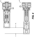
PSU assembly 40 includes thesecond chamber 48 being sealed using the spindle of the ball screw. This causes three significant design changes over other designs that use an actuator rod to move thePSU piston 45. The first is that the overall length of thePSU assembly 40 is significantly reduced to nearly the same length as the standard drive system (i.e. a PSU 16 with fluid on only one side of the piston). The second is that this now bathes the ball screw in brake fluid. And the third is that is eliminates any need for area equalization on thePSU piston 45, since there is no actuator rod to cause an area imbalance.Fig. 4 shows a cut-away diagram of thePSU assembly 40 of the present disclosure with an alternative PSU that includes an actuator rod to move thePSU piston 45, for size reference. -
Figs. 5A - 5C show cut-away diagrams of three different PSUs.Fig. 5A shows afirst PSU assembly 150 with a double-acting configuration includes a pressure-balanced design with fluid on both sides of the piston, and with an actuator rod coupling a ball screw type linear actuator to the piston.Fig. 5B shows asecond PSU assembly 152 in accordance with the present disclosure. Thesecond PSU assembly 152 may be similar or identical to thePSU assembly 40 of the present disclosure, but with a lip seal in place of thering seal 128.Fig. 5C shows athird PSU assembly 154 having a conventional design, with fluid on only one side of the piston. -
Fig. 6A shows a first one-box brake-by-wire device 160 that includes thefirst PSU assembly 150 ofFig. 5A . The first one-box brake-by-wire device 160 includes a first hydraulic control unit (HCU)body 170 having a firsttop surface 171 opposite from theelectric motor 42, with thefirst PSU assembly 150 extending along a side face of thefirst HCU body 170 and substantially beyond and above the firsttop surface 171.Fig. 6B shows a second one-box brake-by-wire device 162 that includes thesecond PSU assembly 152 ofFig. 5B . The second one-box brake-by-wire device 162 includes a second hydraulic control unit (HCU)body 172 having a secondtop surface 173 opposite from theelectric motor 42, with thesecond PSU assembly 152 extending along a side face of thesecond HCU body 172 and protruding slightly beyond and above the secondtop surface 173, but to a lesser extent than thefirst PSU assembly 150 extends above the firsttop surface 171 of thefirst PSU assembly 150.Fig. 6C shows a third one-box brake-by-wire device 164 that includes thethird PSU assembly 154 ofFig. 5C . The third one-box brake-by-wire device 164 includes athird HCU body 174 having a thirdtop surface 175 opposite from theelectric motor 42, with thethird PSU assembly 154 extending along a side face of thethird HCU body 174 ending flush with the thirdtop surface 175. The difference between the PSUs shown onFigs. 5A and 5B show an example of the size and mass savings that may result from the elimination of the separate actuator, and providing the ball screw to be flooded with brake fluid instead of being dry. -
Fig. 7 shows a cross-sectional view of a fourth one-box brake-by-wire device 166. It still maintains a pressurebalanced PSU piston 45. The back side ofpiston seal 140 is exposed to brake pressure from replenishingfluid passageway 54 while the front side ofpiston seal 140 is exposed to pressure fromPSU passageway 50 enabling pressure balance. Thisfourth PSU assembly 156 is shown in a transverse motor configuration, with themotor 42 oriented such that the motor shaft is horizontal and transverse to a master cylinder bore (not shown) in afourth HCU body 176. Thefourth PSU assembly 156 may have a similar or identical configuration to thesecond PSU assembly 152 ofFig. 5B . The fourth one-box brake-by-wire device 166 having a transverse motor configuration may provide for a space savings and eliminate costly motor-to-ECU connectors. This design may include a standard brushless motor driving a planetary geartrain to minimize overall cost, maximize motor efficiency, and minimize motor current draw. Reduced motor current draw can provide for an additional cost savings in electronics for powering the motor. This unique combination of designs: pressure balanced PSU piston with rotary lip seal on spindle and transverse motor layout with integrated planetary gearset make this a truly unique design combination. -
Fig. 8 shows a schematic diagram of the 10-valve brake-by-wire system ofFig. 2 , with additional features, in accordance with an aspect of the present disclosure.Fig. 8 includes a one-box, 10-valve BbW device 220, as an integrated assembly. The 10-valve system is so-named because of its inclusion of ten actuated valves including thePRIV 62, theMCIV 72, plus the eight solenoid valves in thecontrol valve manifold 78.Fig. 8 also shows the 10-valve BbW device 220 that includes an electronic control unit (ECU) 90, with electrical connections for monitoring the various sensors and for controlling the various actuators, such as theelectric motor 42 of thePSU assembly 40, and the solenoid valves. TheECU 90 is also connected to one or moreexternal controllers 92 of a vehicle via a communications network, such as Controller Area Network (CAN bus). TheECU 90 is also configured to control actuation and/or other functions of one or more electric parking brake actuators EPB. TheECU 90 is also configured to receive a parking brake command from aparking brake switch 93 via the communications network. Alternatively or additionally, theparking brake switch 93 may be hardwired to theECU 90. - The 10-valve design shown in
Fig. 8 includes thePSU assembly 40 and themaster cylinder 30. When in brake-by-wire mode and the driver applies the brake pedal, theMCIV 72 is closed, and thePRIV 62 is opened. Fluid is directed from themaster cylinder 30 to thePFE 39 to simulate normal brake pedal force and travel. That same travel information is sent to theECU 90 which subsequently applies the appropriate current to the PSU motor to rotate the ball screw and mechanically displace thePSU piston 45. This causes the fluid to travel through thedual check valves 82, through the ABS applyvalves 80a, and finally reaching the wheel brakes to apply pressure and slow the vehicle. - Since this is an "open" system, meaning the fluid released from the wheel brakes in an ABS stop is not captured but flows back to the reservoir at atmospheric pressure, it is necessary to replenish the PSU. This is accomplished by first closing the
PRIV 62 which traps pressure behind thePSU piston 45. The ball screw andPSU piston 45 are retracted. This forces fluid behind thePSU piston 45 to flow to the front of thePSU piston 45 via thesecond check valve 58. Pressure on both sides of thePSU piston 45 is maintained during replenishment since both sides of thePSU piston 45 displace equal volumes as thePSU piston 45 travels. -
Fig. 9 shows a schematic diagram of a 11-valve brake-by-wire system, in accordance with an aspect of the present disclosure. The 11-valve brake-by-wire system may be similar or identical to the 10-valve system ofFig. 8 , with a few changes discussed herein. The 11-valve brake-by-wire system includes a PFE isolation valve (PFIV) 212, which may be a normally-open solenoid valve, selectively coupling theintermediate fluid passageway 64 and thedisplacement fluid passageway 68. The 11-valve brake-by-wire system also does not include several check valves present in the 10-valve system ofFIG 8 , such as thethird check valve 66, thefourth check valve 69, and thefifth check valve 70. -
Fig. 9 includes a one-box, 11-valve BbW device 320, as an integrated assembly. The 11-valve system is so-named because of its inclusion of eleven actuated valves including thePRIV 62, theMCIV 72, thePFIV 212, plus the eight solenoid valves in thecontrol valve manifold 78. - The 11-valve design shown in
Fig. 9 includes thePSU assembly 40 and themaster cylinder 30. When in brake-by-wire mode and the driver applies the brake pedal, theMCIV 72 is closed, and thePRIV 62 is opened. Fluid from themaster cylinder 30 is directed to thePFE 39 to simulate normal brake pedal force and travel. That same travel information is sent to theECU 90, which subsequently applies the appropriate current to thePSU motor 42 to rotate the ball screw and mechanically displace thePSU piston 45. This causes the fluid to travel through thedual check valves 82, through the ABS applyvalves 80a, and finally reaching the wheel brakes to apply pressure and slow the vehicle. - Since this is an "open" system, meaning the fluid released from the wheel brakes in an ABS stop is not captured but flows back to the reservoir at atmospheric pressure, it is necessary to replenish the PSU. This is accomplished by first closing the
PRIV 62 and thePFIV 212 which traps pressure behind the piston. (ThePFIV 212 eliminates four check valves and permits ease of service bleeding the brakes.) The ball screw andPSU piston 45 are retracted. This forces fluid behind thePSU piston 45 to flow to the front of thePSU piston 45 via thesecond check valve 58. Pressure on both sides of thePSU piston 45 is maintained during replenishment since both sides of thePSU piston 45 displace equal volumes as thePSU piston 45 travels. -
Fig. 10 shows a schematic diagram of a 12-valve brake-by-wire system, in accordance with an aspect of the present disclosure. The 12-valve brake-by-wire system may be similar or identical to the 11-valve system ofFig. 9 , with a few changes discussed herein. The 12-valve brake-by-wire system includes a brake circuit isolation valve (BCIV) 312, which may be a normally-open solenoid valve, selectively coupling thePSU fluid passageway 50 and thesecond brake circuit 76. -
Fig. 10 includes a one-box, 12-valve BbW device 420, as an integrated assembly. The 12-valve system is so-named because of its inclusion of twelve actuated valves including thePRIV 62, theMCIV 72, thePFIV 212, brakecircuit isolation valve 312, plus the eight solenoid valves in thecontrol valve manifold 78. The one-box, 12-valve BbW device 420 ofFig. 10 also includes a Brake Circuit Balance Orifice (BCBO) 314 configured to restrict fluid flow through only thefirst brake circuit 74 to two of thewheel brakes BCBO 314 is connected in line with the supply-side check valve of thedual check valves 82 to regulate fluid flow from thePSU fluid passageway 50 to the corresponding ones of thewheel brakes - The 12-valve design shown in
Fig. 10 includes thePSU assembly 40 and themaster cylinder 30. When in brake-by-wire mode and the driver applies the brake pedal, theMCIV 72 is closed, and thePRIV 62 is opened. Fluid from themaster cylinder 30 is directed to thePFE 39 to simulate normal brake pedal force and travel. That same travel information is sent to theECU 90 which subsequently applies the appropriate current to thePSU motor 42 to rotate the ball screw and mechanically displace the PSU piston. This causes the fluid to travel through theBCIV 312, theBCBO 314, thedual check valves 82, through the ABS applyvalves 80a, and finally reaching thewheel brakes BCBO 314 may equalize flow between two diagonal circuits in a diagonal split system. - Since this is an "open" system, meaning the fluid released from the
wheel brakes fluid reservoir 24 at atmospheric pressure, it is necessary to replenish thePSU assembly 40. This is accomplished by first closing thePRIV 62 and thePFIV 212 which traps pressure behind thePSU piston 45. (ThePFIV 212 eliminates four check valves and permits ease of service bleeding the brakes.) The ball screw andPSU piston 45 are retracted. This forces fluid behind thePSU piston 45 to flow to the front of thePSU piston 45 via thesecond check valve 58. Pressure on both sides of thePSU piston 45 is maintained during replenishment since both sides of thePSU piston 45 displace equal volumes as thePSU piston 45 travels. -
Fig. 11 shows a fifth one-box brake-by-wire device 165 having an axial configuration, with theelectric motor 42 and the piston bore 102 of thePSU assembly 40 axially aligned with themaster cylinder 30, and with afifth HCU 178 located aside the axial arrangement of the PSU and themaster cylinder 30.Fig. 12 shows the fourth one-box brake-by-wire device 166 ofFig. 7 in an assembled condition with thefluid reservoir 24 attached to the top, and theECU 90 attached on a side face of thefourth HCU body 176 opposite from theelectric motor 42.Fig. 13 shows a sixth one-box brake-by-wire device 168 with a motor-up configuration.Fig. 14 shows the third one-box brake-by-wire device 164 ofFig. 6C with a motor-down configuration and in an assembled condition with thefluid reservoir 24 attached to the top, and theECU 90 attached on a side face of thethird HCU body 174 opposite from theelectric motor 42. - As shown on
Fig. 14 , the third one-box brake-by-wire device 164 includes thefluid reservoir 24 mounted on the top surface of thethird HCU body 174 and theelectric motor 42 of thePSU assembly 40 is mounted to the bottom surface of thethird HCU body 174, opposite from thefluid reservoir 24. Also, thethird PSU assembly 154, which includes thePSU housing 100 defining the piston bore 102, does not extend beyond the top surface of thethird HCU body 174. - The one-
box BbW devices box BbW devices PSU assembly 40 axially aligned with themaster cylinder 30, as shown inFig. 11 . Additionally or alternatively, any of the one-box BbW devices electric motor 42 having a motor shaft that extends horizontally and transverse to themaster cylinder 30, as shown inFig. 12 . Additionally or alternatively, any of the one-box BbW devices electric motor 42 located above themaster cylinder 30, as shown inFig. 13 . Additionally or alternatively, any of the one-box BbW devices Fig. 14 . - According to an aspect of the disclosure, a first brake system for motor vehicles is provided. The first brake system may include the 10-valve brake-by-wire system of the present disclosure. The first brake system can be activated by a vehicle driver in a normal brake-by-wire operating mode, via electrical actuation. The first brake system can also be operated by the same driver in at least one fallback operating mode in which one or more of the
wheel brakes brake pedal 36, and without any electrical power. - According to an aspect of the disclosure, the first brake system may include: a brake pedal for actuating a brake master cylinder having a housing and a single piston and which defines a single pressure chamber which is subsequently connected to the
wheel brakes - According to an aspect of the disclosure, the first brake system may further include: a pressure medium reservoir for a pressure medium which is exposed to atmospheric pressure and has a reservoir chamber associated with the pressure chamber.
- According to an aspect of the disclosure, the first brake system may further include: a travel detection device which detects the actuation travel of the brake pedal or at least the piston connected to the brake pedal; a pedal feel emulator which conveys a desired haptic brake pedal feel to the vehicle driver in the brake-by-wire mode, being connected hydraulically directly to the master cylinder pressure chamber;
- According to an aspect of the disclosure, the first brake system may further include: an electrically controllable pressure supply unit which delivers a brake system pressure and consists of a floating piston sealed to the main housing bore and containing at least one anti-rotation feature that connects with at least one groove in the main housing bore which prevents piston rotation but permits piston translation.
- According to an aspect of the disclosure, the first brake system may further include: the pressure supply unit piston displaced by an independently actuated ball screw nut of a ball screw assembly on one end to supply brake system pressure whereas the ball screw spindle of said ball screw assembly is permanently attached to the inner race of a ball bearing assembly whose outer race is permanently attached to a stepped bore in the main housing and whose inner race permits rotation but prevents translation of said ball screw spindle.
- According to an aspect of the disclosure, the first brake system may further include: said ball screw assembly spindle is also sealed to the main housing in a corresponding bore containing a radial lip seal thus permitting brake fluid entrance to the ball screw assembly nut and roller balls, but preventing brake fluid entrance to the area containing the bearing inner race,
- According to an aspect of the disclosure, the first brake system may further include: said ball bearing inner race containing at least one pin on which is rotatably attached a planet gear of a planetary gearset assembly whose outer ring gear is permanently attached to a stepped bore of the main bore and whose sun gear is permanently attached to the output shaft of an electric motor. The motor may be a brushless motor.
- According to an aspect of the disclosure, the first brake system may further include: a normally open valve for isolating the master cylinder from the brake circuit located between the master cylinder outlet port and the wheel brakes.
- According to an aspect of the disclosure, the first brake system may further include: a normally closed valve for isolating the motor side of the electrically controllable pressure source to the reservoir.
- According to an aspect of the disclosure, the first brake system may further include: a series of check valves that allow flow from the pedal feel emulator to the normally closed valve above, but prohibit flow in the opposite direction.
- According to an aspect of the disclosure, the first brake system may further include: a forward flow and reverse flow check valve in parallel to each other and located between the pressure supply unit and two of the wheel brakes with a second forward flow and reverse flow check valve in parallel to each other and located between the pressure supply unit and the remaining pair of wheel brakes.
- According to an aspect of the disclosure, the first brake system may further include: an inlet valve and outlet valve for each of the wheel brakes for setting wheelindividual brake pressures which are derived from signals generated by the electronic control unit where the inlet valves transmit fluid to the wheel brakes in an unactivated state, and limiting or preventing a build-up of wheel pressure in an activated state and the outlet valves preventing an outflow of the pressure medium from the wheel brakes to the reservoir in an inactivated state and permitting and controlling the outflow in an activated state, the inlet valves being closed, so that a reduction in wheel brake pressure takes place.
- According to an aspect of the disclosure, a second brake system for motor vehicles is provided. The second brake system may include the 11-valve brake-by-wire system of the present disclosure. The second brake system can be activated by a vehicle driver in a normal brake-by-wire operating mode, via electrical actuation. The second brake system can also be operated by the same driver in at least one fallback operating mode in which one or more of the
wheel brakes brake pedal 36, and without any electrical power. - According to an aspect of the disclosure, the second brake system may include: a brake pedal for actuating a brake master cylinder having a housing and a single piston and which defines a single pressure chamber which is subsequently connected to the wheel brakes, wherein an actuating force exerted by the brake pedal is exerted on the single piston upon actuation of the brake system by the vehicle driver and the piston is positioned in a starting position by a return spring when the brake pedal is not actuated.
- According to an aspect of the disclosure, the second brake system may also include: a pressure medium reservoir for a pressure medium which is exposed to atmospheric pressure and has a reservoir chamber associated with the pressure chamber.
- According to an aspect of the disclosure, the second brake system may also include: a travel detection device which detects the actuation travel of the brake pedal or at least the piston connected to the brake pedal.
- According to an aspect of the disclosure, the second brake system may also include: a pedal feel emulator which conveys a desired haptic brake pedal feel to the vehicle driver in the brake-by-wire mode, being connected hydraulically directly to the master cylinder pressure chamber.
- According to an aspect of the disclosure, the second brake system may also include: an electrically controllable pressure supply unit which delivers a brake system pressure and consists of a floating piston sealed to the main housing bore and containing at least one anti-rotation feature that connects with at least one groove in the main housing bore which prevents piston rotation but permits piston translation.
- According to an aspect of the disclosure, the second brake system may also include: said pressure supply unit piston displaced by an independently actuated ball screw nut of a ball screw assembly on one end to supply brake system pressure whereas the ball screw spindle of said ball screw assembly is permanently attached to the inner race of a ball bearing assembly whose outer race is permanently attached to a stepped bore in the main housing and whose inner race permits rotation but prevents translation of said ball screw spindle.
- According to an aspect of the disclosure, the second brake system may also include: said ball screw assembly spindle is also sealed to the main housing in a corresponding bore containing a radial lip seal thus permitting brake fluid entrance to the ball screw assembly nut and roller balls, but preventing brake fluid entrance to the area containing the bearing inner race.
- According to an aspect of the disclosure, the second brake system may also include: said ball bearing inner race containing at least one pin on which is rotatably attached a planet gear of a planetary gearset assembly whose outer ring gear is permanently attached to a stepped bore of the main bore and whose sun gear is permanently attached to the output shaft of an electric motor. The motor may be a brushless motor.
- According to an aspect of the disclosure, the second brake system may also include: a normally open valve for isolating the master cylinder from the brake circuit located between the master cylinder outlet port and the wheel brakes.
- According to an aspect of the disclosure, the second brake system may also include: a normally closed valve for isolating the motor side of the electrically controllable pressure source to the reservoir.
- According to an aspect of the disclosure, the second brake system may also include: a normally open valve for isolating the pedal feel emulator from the pressure supply unit during a regeneration cycle.
- According to an aspect of the disclosure, the second brake system may also include: a forward flow and reverse flow check valve in parallel to each other and located between the pressure supply unit and two of the wheel brakes with a second forward flow and reverse flow check valve in parallel to each other and located between the pressure supply unit and the remaining pair of wheel brakes.
- According to an aspect of the disclosure, the second brake system may also include: an inlet valve and outlet valve for each of the wheel brakes for setting wheelindividual brake pressures which are derived from signals generated by the electronic control unit where the inlet valves transmit fluid to the wheel brakes in an unactivated state and limiting or preventing a build-up of wheel pressure in an activated state and the outlet valves preventing an outflow of the pressure medium from the wheel brakes to the reservoir in an unactivated state and permitting and controlling the outflow in an activated state, the inlet valves being closed, so that a reduction in wheel brake pressure takes place.
- According to an aspect of the disclosure, a third brake system for motor vehicles is provided. The third brake system may include the 12-valve brake-by-wire system of the present disclosure. The third brake system can be activated by a vehicle driver in a normal brake-by-wire operating mode, via electrical actuation. The third brake system can also be operated by the same driver in at least one fallback operating mode in which only operation of the brake system by the vehicle driver is possible.
- According to an aspect of the disclosure, the third brake system may include: a brake pedal for actuating a brake master cylinder having a housing and a single piston and which defines a single pressure chamber which is subsequently connected to the wheel brakes, wherein an actuating force exerted by the brake pedal is exerted on the single piston upon actuation of the brake system by the vehicle driver and the piston is positioned in a starting position by a return spring when the brake pedal is not actuated.
- According to an aspect of the disclosure, the third brake system may also include: a pressure medium reservoir for a pressure medium which is exposed to atmospheric pressure and has a reservoir chamber associated with the pressure chamber.
- According to an aspect of the disclosure, the third brake system may also include: a travel detection device which detects the actuation travel of the brake pedal or at least the piston connected to the brake pedal.
- According to an aspect of the disclosure, the third brake system may also include: a pedal feel emulator which conveys a desired haptic brake pedal feel to the vehicle driver in the brake-by-wire mode, being connected hydraulically directly to the master cylinder pressure chamber.
- According to an aspect of the disclosure, the third brake system may also include: an electrically controllable pressure supply unit which delivers a brake system pressure and consists of a floating piston sealed to the main housing bore and containing at least one anti-rotation feature that connects with at least one groove in the main housing bore which prevents piston rotation but permits piston translation.
- According to an aspect of the disclosure, the third brake system may also include: said pressure supply unit piston displaced by an independently actuated ball screw nut of a ball screw assembly on one end to supply brake system pressure whereas the ball screw spindle of said ball screw assembly is permanently attached to the inner race of a ball bearing assembly whose outer race is permanently attached to a stepped bore in the main housing and whose inner race permits rotation but prevents translation of said ball screw spindle.
- According to an aspect of the disclosure, the third brake system may also include: said ball screw assembly spindle is also sealed to the main housing in a corresponding bore containing a radial lip seal thus permitting brake fluid entrance to the ball screw assembly nut and roller balls, but preventing brake fluid entrance to the area containing the bearing inner race.
- According to an aspect of the disclosure, the third brake system may also include: said ball bearing inner race containing at least one pin on which is rotatably attached a planet gear of a planetary gearset assembly whose outer ring gear is permanently attached to a stepped bore of the main bore and whose sun gear is permanently attached to the output shaft of an electric motor. The motor may be a brushless motor.
- According to an aspect of the disclosure, the third brake system may also include: a normally open valve for isolating the master cylinder from the brake circuit located between the master cylinder outlet port and the wheel brakes.
- According to an aspect of the disclosure, the third brake system may also include: a normally open valve for dividing the brake circuits in two equivalent parts.
- According to an aspect of the disclosure, the third brake system may also include: a filtered orifice assembly to provide balanced flow to one of the divided circuits for a diagonal split circuit.
- According to an aspect of the disclosure, the third brake system may also include: a forward flow and reverse flow check valve in parallel to each other and located between the pressure supply unit and two of the wheel brakes with a second forward flow and reverse flow check valve in parallel to each other and located between the pressure supply unit and the remaining pair of wheel brakes.
- According to an aspect of the disclosure, the third brake system may also include: an inlet valve and outlet valve for each of the wheel brakes for setting wheelindividual brake pressures which are derived from signals generated by the electronic control unit where the inlet valves transmit fluid to the wheel brakes in an unactivated state and limiting or preventing a build-up of wheel pressure in an activated state and the outlet valves preventing an outflow of the pressure medium from the wheel brakes to the reservoir in an unactivated state and permitting and controlling the outflow in an activated state, the inlet valves being closed, so that a reduction in wheel brake pressure takes place.
- The foregoing description is not intended to be exhaustive or to limit the disclosure. Individual elements or features of a particular embodiment are generally not limited to that particular embodiment, but, where applicable, are interchangeable and can be used in a selected embodiment, even if not specifically shown or described. The same may also be varied in many ways. Such variations are not to be regarded as a departure from the disclosure, and all such modifications are intended to be included within the scope of the disclosure.
Claims (15)
- An electro-hydraulic brake system comprising:a single-circuit master cylinder (MC) (30) fluidly coupled to a first MC fluid passageway (34) and configured to supply fluid into the first MC fluid passageway (34) in response to pressing force on a brake pedal (36) coupled thereto;a pressure supply unit (PSU) assembly (40) including an electric motor (42) coupled to a ball screw actuator (118), a PSU housing (100) defining a piston bore (102) having a terminal end (130) opposite the electric motor (42), and a PSU piston (45) disposed within the piston bore (102) and movable by the ball screw actuator (118) through the piston bore (102) and dividing the piston bore (102) into a first chamber (46) and a second chamber (48), with each of the first chamber (46) and the second chamber (48) containing a hydraulic fluid; and wherein the ball screw actuator (118) includes an actuator nut assembly (120, 124) having a plurality of ball bearings (124) each disposed within the piston bore (102) and submerged in the hydraulic fluid.
- The electro-hydraulic brake system of Claim 1, wherein the PSU piston (45) has a cup shape, and wherein the actuator nut (120) and the plurality of ball bearings (124) are each disposed within the cup shape of the PSU piston (45).
- The electro-hydraulic brake system of Claim 1 or 2, wherein the PSU assembly (40) further comprises: a spindle (122) driven by the electric motor (42) and extending through a ring seal (128) to prevent fluid from leaking out of the piston bore (102).
- The electro-hydraulic brake system of any one of Claims 1 to 3, further comprising:a PSU fluid passageway (50) providing fluid communication from the first chamber (46) of the PSU assembly (40) to at least one wheel brake (22a, 22b, 22c, 22d);a replenishing fluid passageway (54) in fluid communication with the second chamber (48) of the PSU assembly (40); anda check valve (58) configured to allow fluid flow from the replenishing fluid passageway (54) to the PSU fluid passageway (50) while blocking fluid flow in an opposite direction.
- The electro-hydraulic brake system of any one of Claims 1 to 4, further comprising:at least one brake circuit (74, 76) configured to transmit fluid from the PSU assembly (40) to at least one wheel brake (22a, 22b, 22c, 22d);a control valve manifold (78) including at least one of an apply valve and a release valve for controlling fluid flow between the at least one brake circuit (74, 76) and the at least one wheel brake (22a, 22b, 22c, 22d);wherein the pressure supply unit assembly (40) includes at least one PSU port (132, 134) configured to discharge fluid therefrom; andwherein the at least one PSU port (132, 134) is in fluid communication with the control valve manifold (78) via the at least one brake circuit (74, 76) and without any actuated valves therebetween.
- The electro-hydraulic brake system of any one of Claims 1 to 5, further comprising:a pedal feel emulator (PFE) (39) including a PFE piston movable through a PFE bore and separating an upper chamber from a lower chamber;wherein the lower chamber of the PFE (39) is fluidly coupled to the second chamber (48) of the PSU assembly (40) to convey fluid from the lower chamber of the PFE (39) to the second chamber (48) of the PSU assembly (40) in response to a compression of the PFE (39); andwherein the first MC fluid passageway (34) is fluidly coupled to the upper chamber of the PFE (39) to provide a fluid path from the master cylinder (30) into the upper chamber of the PFE (39).
- The electro-hydraulic brake system of Claim 6, further comprising:a fluid reservoir (24) holding a hydraulic fluid and supplying the hydraulic fluid to the master cylinder (30);a return fluid passageway (52) in direct fluid communication with the fluid reservoir (24);an intermediate fluid passageway (64) in fluid communication with each of the second chamber (48) of the piston bore (102) and the lower chamber of the PFE (39); anda PSU reservoir isolation valve (62) selectively controlling fluid communication between the return fluid passageway (52) and the intermediate fluid passageway (64).
- The electro-hydraulic brake system of Claim 7, further comprising a check valve (66) disposed between the second chamber (48) of the piston bore (102) and the intermediate fluid passageway (64) and configured to allow fluid flow from the second chamber (48) of the piston bore (102) to the intermediate fluid passageway (64) while blocking fluid flow in an opposite direction.
- The electro-hydraulic brake system of Claim 7, further comprising:
a check valve (70) disposed between the lower chamber of the PFE (39) and the intermediate fluid passageway (64) and configured to allow fluid flow from the lower chamber of the PFE (39) to the intermediate fluid passageway (64) while blocking fluid flow in an opposite direction; or a PFE isolation valve (212) selectively controlling fluid communication between the lower chamber of the PFE (39) and the intermediate fluid passageway (64). - The electro-hydraulic brake system of any one of Claims 1 to 3, further comprising:a first brake circuit (74) and a second brake circuit (76), each configured to transmit fluid from the PSU assembly (40) to at least one corresponding wheel brake (22a, 22b, 22c, 22d);a PSU fluid passageway (50) providing fluid communication from the PSU assembly (40) to the first brake circuit (74); anda brake circuit isolation valve (312) selectively controlling fluid communication between the PSU fluid passageway (50) and the second brake circuit (76).
- The electro-hydraulic brake system of any one of Claims 1 to 3, further comprising:a PSU fluid passageway (50) configured to transmit fluid from the PSU assembly (40) to at least one wheel brake (22a, 22b, 22c, 22d);a control valve manifold (78) including at least one of an apply valve and a release valve for controlling fluid flow between the PSU fluid passageway (50) and the at least one wheel brake (22a, 22b, 22c, 22d); anda bi-directional check valve (82) disposed between PSU fluid passageway (50) and the control valve manifold (78) and configured to allow fluid flow in either of two opposite directions therebetween only when a differential pressure thereacross is above a predetermined amount.
- The electro-hydraulic brake system of any one of Claims 1 to 3, further comprising:a first brake circuit (74) and a second brake circuit (76), each configured to transmit fluid from the PSU assembly (40) to at least one corresponding wheel brake (22a, 22b, 22c, 22d);a PSU fluid passageway (50) providing fluid communication from the PSU assembly (40) to the first brake circuit (74) and the second brake circuit (76); anda brake circuit balance orifice (314) configured to restrict a flow of fluid through only the first brake circuit (74).
- The electro-hydraulic brake system of any one of Claims 1 to 6, further comprising:a hydraulic control unit (HCU) body (170, 172, 174) defining a top surface (171, 173, 175) and a bottom surface opposite the top surface (171, 173, 175) and including a PSU housing (100) defining the piston bore (102);a fluid reservoir (24) mounted on the top surface (171, 173, 175) of the HCU body (170, 172, 174); andwherein the electric motor (42) of the PSU assembly (40) is mounted to the bottom surface of the HCU body (170, 172, 174),in particular wherein the PSU assembly (154) does not extend beyond the top surface (175) of the HCU body (174).
- A pressure supply unit (PSU) assembly for the electro-hydraulic brake system of Claim 1 or 2 comprising:the electric motor (42);the ball screw actuator (118) including a spindle (122) coupled to the electric motor (42) and configured to transfer rotary motion to linear motion;the PSU housing (100) coupled to the electric motor (42); andthe PSU piston (45) disposed within the piston bore (102) and translatable by the ball screw actuator (118) through the piston bore (102),wherein the ball screw actuator (118) includes the actuator nut assembly (120, 124) having the plurality of ball bearings (124) each disposed within the second chamber (48) of the piston bore (102) and submerged in the hydraulic fluid.
- The PSU assembly (40) of Claim 14, wherein the spindle (122) extends through a ring seal (128) to prevent fluid from leaking out of the piston bore (102), in particular wherein the ring seal (128) includes a lip seal, in particular wherein the PSU assembly (40) further comprises a gear set (126) driven by the electric motor (42) and configured to drive the spindle (122) at a slower speed than a speed of the electric motor (42).
Applications Claiming Priority (2)
| Application Number | Priority Date | Filing Date | Title |
|---|---|---|---|
| US202163257097P | 2021-10-18 | 2021-10-18 | |
| CN202211204184.4A CN115614404B (en) | 2021-10-18 | 2022-09-29 | Brake-by-wire system including pressure balanced PSU piston with wet ball screw |
Publications (1)
| Publication Number | Publication Date |
|---|---|
| EP4166402A1 true EP4166402A1 (en) | 2023-04-19 |
Family
ID=83898454
Family Applications (1)
| Application Number | Title | Priority Date | Filing Date |
|---|---|---|---|
| EP22201956.4A Pending EP4166402A1 (en) | 2021-10-18 | 2022-10-17 | Brake-by-wire system including pressure balanced psu piston with wetted ball screw |
Country Status (4)
| Country | Link |
|---|---|
| US (1) | US20230119335A1 (en) |
| EP (1) | EP4166402A1 (en) |
| JP (1) | JP7498242B2 (en) |
| KR (1) | KR102718915B1 (en) |
Families Citing this family (5)
| Publication number | Priority date | Publication date | Assignee | Title |
|---|---|---|---|---|
| US12208777B2 (en) * | 2021-05-24 | 2025-01-28 | Bwi (Shanghai) Co., Ltd. | Brake-by-wire system with pressure balanced PSU piston |
| JP7493016B2 (en) * | 2021-12-07 | 2024-05-30 | ビーダブリュアイ(シャンハイ)カンパニー リミテッド | Brake-by-wire module with pressure balanced PSU piston with fluid-immersed ball screw and backup pump assembly |
| JP2024161810A (en) * | 2023-05-08 | 2024-11-20 | 株式会社アドヴィックス | Hydraulic Pressure Generator |
| JP2024161809A (en) * | 2023-05-08 | 2024-11-20 | 株式会社アドヴィックス | Hydraulic Pressure Generator |
| US20260001518A1 (en) | 2024-06-27 | 2026-01-01 | Bwi (Shanghai) Co., Ltd. | Redundant brake-by-wire system |
Citations (5)
| Publication number | Priority date | Publication date | Assignee | Title |
|---|---|---|---|---|
| US20140354036A1 (en) * | 2013-05-29 | 2014-12-04 | Hyundai Mobis Co., Ltd. | Electronic hydraulic brake device |
| EP2569192B1 (en) * | 2010-05-10 | 2017-10-18 | Lucas Automotive GmbH | Hydraulic assembly for a vehicle brake system |
| US20200189542A1 (en) * | 2018-12-13 | 2020-06-18 | Hyundai Motor Company | Electric brake booster equipped with a pressure balance detecting device |
| KR20200072602A (en) * | 2018-12-12 | 2020-06-23 | 현대자동차주식회사 | Electric brake booster with pressure balancing structure |
| US20210261109A1 (en) * | 2020-02-26 | 2021-08-26 | ZF Active Safety US Inc. | Vehicle brake system |
Family Cites Families (13)
| Publication number | Priority date | Publication date | Assignee | Title |
|---|---|---|---|---|
| JPH0565060A (en) * | 1991-09-06 | 1993-03-19 | Akebono Brake Ind Co Ltd | Safety mechanism of brake control device for car |
| JP3849583B2 (en) * | 2001-08-22 | 2006-11-22 | 株式会社デンソー | Electric brake device |
| DE102007004494A1 (en) * | 2006-07-12 | 2008-01-17 | Continental Teves Ag & Co. Ohg | Electrohydraulic control system for actuating an actuator in a motor vehicle |
| JP6539162B2 (en) * | 2015-09-07 | 2019-07-03 | Kyb株式会社 | Brake drive device and brake system |
| DE102015223507A1 (en) * | 2015-11-27 | 2017-06-01 | Robert Bosch Gmbh | Piston pump unit |
| KR102382574B1 (en) * | 2017-05-17 | 2022-04-05 | 주식회사 만도 | Electric brake system |
| US11535227B2 (en) * | 2017-12-31 | 2022-12-27 | ZF Active Safety US Inc. | Vehicle brake system and self-diagnostic testing |
| CN111655556B (en) * | 2017-12-31 | 2023-08-22 | Zf主动安全美国股份公司 | Vehicle brake system and method of detecting piston positioning of a plunger assembly |
| US20210155215A1 (en) * | 2018-04-04 | 2021-05-27 | ZF Active Safety US Inc. | Vehicle brake system with secondary brake module |
| DE202019101586U1 (en) * | 2019-02-12 | 2020-05-13 | Ipgate Ag | Packaging for a braking system |
| US12208777B2 (en) * | 2021-05-24 | 2025-01-28 | Bwi (Shanghai) Co., Ltd. | Brake-by-wire system with pressure balanced PSU piston |
| US12311902B2 (en) * | 2021-08-12 | 2025-05-27 | ZF Active Safety US Inc. | Apparatus and method for control of a hydraulic brake system |
| JP7493016B2 (en) * | 2021-12-07 | 2024-05-30 | ビーダブリュアイ(シャンハイ)カンパニー リミテッド | Brake-by-wire module with pressure balanced PSU piston with fluid-immersed ball screw and backup pump assembly |
-
2022
- 2022-10-17 US US17/967,819 patent/US20230119335A1/en active Pending
- 2022-10-17 EP EP22201956.4A patent/EP4166402A1/en active Pending
- 2022-10-18 KR KR1020220134051A patent/KR102718915B1/en active Active
- 2022-10-18 JP JP2022166667A patent/JP7498242B2/en active Active
Patent Citations (5)
| Publication number | Priority date | Publication date | Assignee | Title |
|---|---|---|---|---|
| EP2569192B1 (en) * | 2010-05-10 | 2017-10-18 | Lucas Automotive GmbH | Hydraulic assembly for a vehicle brake system |
| US20140354036A1 (en) * | 2013-05-29 | 2014-12-04 | Hyundai Mobis Co., Ltd. | Electronic hydraulic brake device |
| KR20200072602A (en) * | 2018-12-12 | 2020-06-23 | 현대자동차주식회사 | Electric brake booster with pressure balancing structure |
| US20200189542A1 (en) * | 2018-12-13 | 2020-06-18 | Hyundai Motor Company | Electric brake booster equipped with a pressure balance detecting device |
| US20210261109A1 (en) * | 2020-02-26 | 2021-08-26 | ZF Active Safety US Inc. | Vehicle brake system |
Also Published As
| Publication number | Publication date |
|---|---|
| JP2023060842A (en) | 2023-04-28 |
| JP7498242B2 (en) | 2024-06-11 |
| KR102718915B1 (en) | 2024-10-18 |
| US20230119335A1 (en) | 2023-04-20 |
| KR20230055384A (en) | 2023-04-25 |
Similar Documents
| Publication | Publication Date | Title |
|---|---|---|
| US20230119335A1 (en) | Brake-by-wire system including pressure balanced psu piston with wetted ball screw | |
| US20240391439A1 (en) | Vehicle axle having electric drive motors, an electrohydraulic brake and additional modules such as a transmission, torque vectoring and a parking brake | |
| US11590950B2 (en) | Electric brake system and operating method thereof | |
| CN105691372B (en) | Electric brake system | |
| CN105691370A (en) | Electric brake system | |
| KR20110036109A (en) | Automotive Braking System | |
| US12208777B2 (en) | Brake-by-wire system with pressure balanced PSU piston | |
| CN113966290A (en) | Brake system and control method of brake system | |
| US11993233B2 (en) | Electric brake system and operation method | |
| US20220242381A1 (en) | Electronic brake system and method for operating same | |
| EP3885601A1 (en) | Electronic brake system and method for operating same | |
| CN113830057B (en) | Electrohydraulic brake system and pressure supply unit therefor | |
| CN112141067B (en) | Braking system with integrated electro-hydraulic braking source wheel side coupling device and control method thereof | |
| US12594918B2 (en) | Brake-by-wire module including pressure balanced PSU piston with wetted ball screw and backup pump assembly | |
| CN115614404B (en) | Brake-by-wire system including pressure balanced PSU piston with wet ball screw | |
| CN114148306A (en) | Automobile braking system and control method of automobile braking system | |
| US11912251B2 (en) | Electric brake system | |
| CN212861419U (en) | Hydraulic balanced brake system for vehicle | |
| CN115848332B (en) | Line control brake module comprising pressure balance piston of wet ball screw and standby pump assembly | |
| US12522190B2 (en) | Electric brake system | |
| KR102590726B1 (en) | Electric brake system | |
| KR102893397B1 (en) | Electric brake system and Operating method of thereof |
Legal Events
| Date | Code | Title | Description |
|---|---|---|---|
| PUAI | Public reference made under article 153(3) epc to a published international application that has entered the european phase |
Free format text: ORIGINAL CODE: 0009012 |
|
| STAA | Information on the status of an ep patent application or granted ep patent |
Free format text: STATUS: THE APPLICATION HAS BEEN PUBLISHED |
|
| AK | Designated contracting states |
Kind code of ref document: A1 Designated state(s): AL AT BE BG CH CY CZ DE DK EE ES FI FR GB GR HR HU IE IS IT LI LT LU LV MC ME MK MT NL NO PL PT RO RS SE SI SK SM TR |
|
| STAA | Information on the status of an ep patent application or granted ep patent |
Free format text: STATUS: REQUEST FOR EXAMINATION WAS MADE |
|
| 17P | Request for examination filed |
Effective date: 20231019 |
|
| RBV | Designated contracting states (corrected) |
Designated state(s): AL AT BE BG CH CY CZ DE DK EE ES FI FR GB GR HR HU IE IS IT LI LT LU LV MC ME MK MT NL NO PL PT RO RS SE SI SK SM TR |
|
| STAA | Information on the status of an ep patent application or granted ep patent |
Free format text: STATUS: EXAMINATION IS IN PROGRESS |
|
| 17Q | First examination report despatched |
Effective date: 20250327 |