EP4166394A1 - Gripping system for an industrial vehicle - Google Patents
Gripping system for an industrial vehicle Download PDFInfo
- Publication number
- EP4166394A1 EP4166394A1 EP21202224.8A EP21202224A EP4166394A1 EP 4166394 A1 EP4166394 A1 EP 4166394A1 EP 21202224 A EP21202224 A EP 21202224A EP 4166394 A1 EP4166394 A1 EP 4166394A1
- Authority
- EP
- European Patent Office
- Prior art keywords
- closure member
- gripping system
- truck
- gripping
- grip
- Prior art date
- Legal status (The legal status is an assumption and is not a legal conclusion. Google has not performed a legal analysis and makes no representation as to the accuracy of the status listed.)
- Granted
Links
Images


Classifications
-
- B—PERFORMING OPERATIONS; TRANSPORTING
- B60—VEHICLES IN GENERAL
- B60R—VEHICLES, VEHICLE FITTINGS, OR VEHICLE PARTS, NOT OTHERWISE PROVIDED FOR
- B60R3/00—Arrangements of steps or ladders facilitating access to or on the vehicle, e.g. running-boards
- B60R3/02—Retractable steps or ladders, e.g. movable under shock
-
- B—PERFORMING OPERATIONS; TRANSPORTING
- B60—VEHICLES IN GENERAL
- B60R—VEHICLES, VEHICLE FITTINGS, OR VEHICLE PARTS, NOT OTHERWISE PROVIDED FOR
- B60R3/00—Arrangements of steps or ladders facilitating access to or on the vehicle, e.g. running-boards
- B60R3/005—Catwalks, running boards for vehicle tops, access means for vehicle tops; Handrails therefor
-
- B—PERFORMING OPERATIONS; TRANSPORTING
- B60—VEHICLES IN GENERAL
- B60N—SEATS SPECIALLY ADAPTED FOR VEHICLES; VEHICLE PASSENGER ACCOMMODATION NOT OTHERWISE PROVIDED FOR
- B60N3/00—Arrangements or adaptations of other passenger fittings, not otherwise provided for
- B60N3/02—Arrangements or adaptations of other passenger fittings, not otherwise provided for of hand grips or straps
-
- B—PERFORMING OPERATIONS; TRANSPORTING
- B62—LAND VEHICLES FOR TRAVELLING OTHERWISE THAN ON RAILS
- B62D—MOTOR VEHICLES; TRAILERS
- B62D33/00—Superstructures for load-carrying vehicles
- B62D33/06—Drivers' cabs
Definitions
- This disclosure relates to a gripping system for equipping a heavy-duty vehicle, in particular a truck.
- the front of the truck may be equipped with a handle extending horizontally and located near the bottom of the windscreen.
- the person intending to clean the windscreen may climb by stepping on a footboard and at the same time catching the handle with one hand.
- the person can then clean the windscreen with her free hand, while still holding the handle to keep balance.
- the person can get down while still taking support from the handle.
- Several handles can be disposed along the width of the truck, to provide support in several locations so the entire width of the windscreen can easily be accessed.
- Such handles usually protrude from the front surface of the truck and impair the air flow on the front surface of the truck.
- the drag coefficient of the truck gets higher, which ultimately means higher energy consumption for driving the truck.
- whistling noise may appear at certain speeds because of the protrusion of the handle.
- a gripping system for helping a user climbing over a substantially vertical surface of an industrial vehicle, the gripping system comprising :
- the grip member is housed in a recessed area 3 which can be closed by a closure member.
- a closure member When the grip member 2 is not in use, it doesn't protrude from the external surface of the bodywork /cabin of the vehicle. The aerodynamic drag is therefore reduced.
- a user wants to use the grip member for climbing over the surface of the vehicle, he just has to push the flap open to access the grip member. Vehicle efficiency is optimized without compromising ease of use.
- the industrial vehicle can be a truck, for example a tractor truck trailer / carrier, or a dump truck.
- the industrial vehicle can also be a bus.
- the closure member is configured to be flush with the bodywork element when the closure member is in the first position.
- the shape of the bodywork can be smooth and sleek when the grip member is not in use.
- the aerodynamic drag of the truck 100 is not impaired by the presence of the grip member in the airstream around the bodywork. Furthermore, the risk of having whistling noises due to the presence of the grip member is eliminated, since the grip member is not in the air flow.
- the gripping system comprises an elastic spring configured to deform when the closure member is moved from the first position to the second position.
- the elastic spring is preloaded so that a minimal force to be exerted to move the closure member from the first position to the second position is higher than a predetermined threshold.
- the elastic spring is an helical spring.
- the closure member is rotatable along a rotation axis.
- the elastic spring is a torsion spring.
- the torsion spring is coaxial with a rotation axis of the closure member.
- the closure member is rotatable around a rotation axis, and the rotation axis of the closure member is horizontal when the gripping system is orientated in the nominal installation position in the industrial vehicle.
- the rotation axis of the closure member is vertical when the gripping system is orientated in the nominal installation position.
- the grip member is located below a bottom edge of the closure member 5.
- the closure member is moved inwards of the recessed area when the closure member is moved from the first position to the second position.
- the closure member is configured to swing upward when the closure member is moved from the first position to the second position.
- the closure member is configured to swing downward when the closure member is moved from the first position to the second position.
- the closure member has an angular stroke comprised between 70° and 110°.
- the grip member is a handle.
- the grip member is a grabbing pad.
- the gripping system further comprises :
- the locking mechanism comprises a locking pin configured to be inserted in a bore of the closure member.
- the locking pin can have a translation motion along an axis.
- the locking mechanism comprises a cable linking the step and the locking pin.
- the gripping system further comprises :
- the actuation device comprises a cable linking the closure member and the step.
- a first end of the linking cable is fixed to the step and a second end of the cable is fixed to the closure member.
- the step is horizontally hinged.
- the first end of the cable is distant from the rotation axis of the step.
- the second end of the cable is distant from the rotation axis of the closure member.
- the gripping system comprises a position sensor configured for detecting a position of the step
- the actuation device comprises an electric motor and a transmission mechanism configured to move the closure member from the first position to the second position when the step is in the deployed position.
- the electric motor and the transmission mechanism are configured to move the closure member from the second position to the first position when the step is in the stowed position.
- the gripping system comprises a safety switch configured to deactivate the actuation device.
- the transmission mechanism comprises a gear train.
- the gear train comprises a worm-screw which drives a gear.
- the invention also relates to a truck comprising a gripping system as described earlier.
- the safety switch is configured to deactivate the actuation device when the ignition key of the truck is in the powered-up position.
- the bodywork element in which the grip member is installed is a front surface of the truck.
- an axis of rotation of the step 7 is parallel to a transverse axis of the truck.
- an axis of rotation of the step is parallel to a longitudinal axis of the truck.
- the grip member may extend transversely along more than one half of a width of the truck 100.
- the truck may comprise at least two gripping systems as described earlier.
- the at least two gripping systems may have a common closure member.
- the at least two gripping systems may be independent.
- each gripping system has its own closure member and its own associated grip member.
- Figure 8 illustrates an industrial vehicle 100 comprising a gripping system 1 according to the invention.
- the industrial vehicle 100 is a truck.
- the industrial vehicle can be a dump truck, or a bus.
- the present invention relates to a gripping system 1 for helping a user climbing over a substantially vertical surface 50 of an industrial vehicle 100, the gripping system 1 comprising :
- substantially vertical means that the surface 50 to climb over is vertical or close to vertical, depending on the exact shape of the bodywork of the industrial vehicle.
- the surface 50 forms an angle higher than 70° with the surface of the road on which the industrial vehicle is driven.
- a gripping system 1 provides a strong support to keep one's balance and reduce the risk of fall and resulting injuries.
- the gripping system 1 is also called a hand holding system, or a hand support system.
- the grip member 2 is housed in a recessed area 3 which can be closed by a closure member 5.
- the recessed area 3 forms a cavity. This cavity is not necessarily closed.
- the bottom of the cavity may comprise holes to ensure drainage of rainwater or possible condensation of humidity.
- the closure member 5 of the recessed area is for example a flap.
- Drag coefficient is therefore reduced, and aerodynamic noises are eliminated, or at least largely reduced.
- the closure member 5 may always be pushed by the user.
- the closure member 5 can be moved as well by other means which can provide an automatic actuation of the closure member, as it will described in detail later.
- the closure member 5 When the closure member 5 is in the first position C, it blocks the access to the grip member 2.
- the first position C is called blocking position.
- the grip member 2 is concealed when the closure member 5 is in the first position C.
- the first position C is also called concealed position.
- the grip member 2 is accessible when the closure member 5 is in the second position O.
- a user can grasp the grip member 2 so that he can climb over the vertical surface 50 by supporting at least a fraction of his weight on the grip member 2.
- the second position O is said revealing position. The user can secure its standing position; improving its safety while working along the substantially vertical surface of the industrial vehicle.
- the closure member 5 should be large enough to provide access from various angles of approach of the forearm of the user.
- the closure member 5 is for example 20 centimeters wide and 10 centimeters high.
- the closure member 5 may be a metal sheet.
- the closure member 5 may be a plastic injected part.
- the closure member 5 may be the same color as the neighboring bodywork for better integration.
- the closure member 5 is for example rectangular. Any shape is possible, as long as it is adapted to the passage of a hand and wrist of the users, and as long as the closure member 5 can be moved from the blocking position C to the revealing position O without interfering with other elements.
- the closure member 5 is configured to be flush with the bodywork element 4 when the closure member 5 is in the first position C. Therefore, the shape of the bodywork can be smooth and sleek when the grip member 2 is not in use. When the truck 100 is running, the aerodynamic drag of the truck 100 is not compromised by the presence of the grip member 2.
- the gripping system comprises an elastic spring 6 configured to deform when the closure member 5 is moved from the first position C to the second position O.
- the closure member 5 is moved from the first position C to the second position O against the action of an elastic spring 6.
- the elastic spring 6 brings back the closure member 5 in the first position C when the user releases his grip on the grip member 2. Therefore, the closure member 5 comes back into the first position once a user removes his hand from the gripping system 1.
- the elastic spring 6 is preloaded so that a minimal force to be exerted to move the closure member 5 from the first position C to the second position O is higher than a predetermined threshold Th.
- the elastic spring 6 is preloaded, or pre-stressed, so that it tends to press the closure member 5 against an end-stop that defines the position of the closure member 5 when it is in the first position C.
- the elastic spring 6 prevents the closure member 5 from moving from the first position C to the second position O when the user exerts no action on the closure member 5.
- the elastic spring preload is designed so that the closure member 5 doesn't move under the action of the aerodynamic pressure or under the action of road vibrations, ensuring that the closure member 5 remains firmly in the first position C when the gripping system 1 is not in use. The efficiency of the device is maintained even the vehicle travels at maximum speed with wind opposite to travelling direction, and possible rattling noises of closure member 5 oscillations are avoided.
- the elastic spring 6 is an helical spring.
- the elastic spring 6 can be compressed when the closure member 5 is moved from the first position C to the second position O.
- the elastic spring 6 can be stretched when the closure member 5 is moved from the first position C to the second position O.
- the closure member 5 is rotatable along a rotation axis A5.
- the elastic spring 6 is a torsion spring.
- the torsion spring is coaxial with a rotation axis A5 of the closure member 5.
- the closure member 5 is rotatable around a rotation axis A5, and the rotation axis A5 of the closure member 5 is horizontal when the gripping system 1 is orientated in the nominal installation position in the industrial vehicle 100.
- nominal installation position in the industrial vehicle 100 is the position when the gripping system 1 is fully assembled on a vehicle, with the vehicle rolling on a horizontal road.
- the axis of the rotation of the closure member 5 is parallel to the plane defined by a longitudinal axis X and a transverse axis Y of the industrial vehicle.
- the longitudinal axis X is by definition the front-rear axis of the vehicle
- the transverse axis Y is the left-right axis.
- the top edge and bottom edge of the closure member 5, upwards and downward directions are defined when the gripping system 1 is orientated the same way as its nominal installation position in the industrial vehicle 100.
- the rotation axis of the closure member 5 is vertical when the gripping system 1 is orientated in the nominal installation position.
- the rotation axis of the closure member 5 is in this case perpendicular to both the longitudinal axis X and the transverse axis Y of the industrial vehicle 100.
- the grip member 2 is vertically located below a bottom edge 22 of the closure member 5.
- the closure member 5 is moved inwards of the recessed area 3 when the closure member 5 is moved from the first position C to the second position O.
- the shutter 5 is moved towards the interior of the recessed area 3 when the closure member 5 is rotated from the first position C to the second position O.
- the closure member 5 doesn't protrude out of the cabin body surface.
- the closure member 5 is configured to swing upward when the closure member 5 is moved from the first position C to the second position O.
- the closure member 5 is configured to swing away from the grip member 2.
- the rotation axis A5 of the closure member 5 is located near a top edge of the closure member 5.
- the closure member 5 is configured to swing downward when the closure member 5 is moved from the first position C to the second position O.
- the rotation axis A5 of the closure member 5 is located near a bottom edge 22 of the closure member 5.
- the part A of the figure represents the gripping system 1 with the grip member 2 in the first position C.
- the part B of these figures represent the gripping system 1 with a hand H of a user in contact with the grip member 2.
- the closure member 5 has an angular stroke T5 comprised between 70° and 110°. In other words, the closure member 5 rotates by an angle T5 comprised between 70° and 110° when it is moved from the first position C to the second position O.
- the grip member 2 is a handle.
- the grip member 2 has an elongated shape, and a clearance 23 is left between this elongated shape and the facing wall 24.
- the user can encircle the elongated shape with his hand to get a strong support.
- the handle can be a metal sheet put into shape, like a steel sheet.
- the handle can also be an aluminum casting.
- the grip member 2 is a grabbing pad.
- the grabbing pad forms a protrusion that the hand of the user can grab.
- the grabbing pad 2 can be a rubber block.
- the grabbing pad can also be an injected plastic part.
- the gripping system 1 further comprises :
- the rotatable step 7, illustrated on figure 9 is configured for providing a bearing surface on which a user U can lean when the step 7 is in the deployed position D.
- the step 7 protrudes from the front of the truck 100 when the step 7 is in the deployed position D.
- the step 7 can be deployed by a user when he needs to climb, and put back in stowed position when it's not needed any more
- the user U can hoist himself up along the substantially vertical surface 50 of the truck 100 by placing one foot on the deployed step 7 and grabbing at the same time the grip member 2 with one hand H to support his weight and improve his balance. He can then with his free hand perform a task such as washing the windscreen 20 of the truck 100.
- the rotatable step 7 is optional.
- the step 7 When the step 7 is in stowed position S, it remains within the external boundaries of the bodywork of the truck. There's no protrusion of the step 7 when it is in the stowed position S.
- the stowed position S of the step 7 is represented with a dotted line and the deployed position D is represented with a plain line.
- the locking mechanism 16 is illustrated on figure 4 .
- the locking mechanism 16 comprises a locking pin 17 configured to be inserted in a bore 18 of the closure member 5.
- the locking pin 17 can have a translation motion along an axis A17.
- the locking mechanism 16 comprises a cable 19 linking the step 7 and the locking pin 17.
- a first end 19a of the linking cable 19 is fixed to the step 7 and a second end 19b of the cable 19 is fixed to the locking pin 17.
- the cable 19 is represented in two separated portions only for clarity.
- a fifth and a sixth embodiment provide automated opening of the closure member 5.
- the gripping system 1 further comprises :
- deploying the step 7 automatically moves the closure member 5 so that the grip member 2 is readily available. The user doesn't have to push the closure member 5 opened to access the grip member 2.
- the actuation device 11 comprises a cable 12 linking the closure member 5 and the step 7.
- a first end 12a of the linking cable 12 is fixed to the step 7 and a second end 12b of the cable 12 is fixed to the closure member 5.
- the step 7 is horizontally hinged, as represented on figure 6 and figure 9 .
- the first end 12a of the cable 12 is distant from the rotation axis A7 of the step 7.
- the axis of rotation A7 of the step 7 is here parallel to a transverse axis Y of the truck.
- the second end 12b of the cable 12 is distant from the rotation axis A5 of the closure member 5.
- the gripping system comprises a position sensor 13 configured for detecting a position of the step 7
- the actuation device 11 comprises an electric motor 14 and a transmission mechanism 15 configured to move the closure member 5 from the first position C to the second position O when the step 7 is in the deployed position D.
- the position sensor 13 is configured for detecting transitions between the stowed position S of the step 7 and the deployed position D of the step 7.
- the actuation device 11 is activated to move the closure member 5 from the first position C to the second position O when a transition from the stowed position S of the step 7 to the deployed position D of the step 7 is detected.
- an electronic control unit 25 receives the different signals and activates or deactivates the electric motor 14 in order to control the actuation device 11 and the position of the closure member 5.
- the position sensor 13 can be a switch. In this case, the output signal can only take two different values. In short, the position sensor 13 can only detect two different positions. The position sensor 13 can also deliver a continuous information. Output signal can vary continuously across a range defined by a minimum position and a maximum position.
- the position sensor 13 can for example be a Hall sensor associated with a magnetic target fixed to the step 7.
- the electric motor 14 and the transmission mechanism 15 are configured to move the closure member 5 from the second position O to the first position C when the step 7 is in the stowed position S.
- the actuation device 11 is activated to move the closure member 5 from the second position O to the first position C when a transition from the deployed position D of the step 7 and the stowed position S of the step 7 is detected.
- the closure member 5 is opened only when the step 7 is in the deployed position D. In short, the closure member 5 is opened only when the gripping system 1 is likely to be used.
- the transmission mechanism 15 comprises a gear train.
- the gear train may comprise a worm-screw which drives a gear.
- the gripping system further comprises a safety switch 21 configured to deactivate the actuation device 11.
- the role of the safety switch 21 is to prevent the closure member 5 to be moved in the second position O in which the recessed area 3 is opened whereas the safety conditions are not met. In that case, the closure member 5 has to remain in the first position C in which the closure member closes the recessed area 3. Therefore, the gripping member 2 remains unusable as long as the safety conditions are not met.
- the truck 100 comprises an ignition key with two stable positions.
- a first stable position is a powered-down position in which the various electric systems of the truck are deactivated.
- a second stable position is a powered-up position in which the various electric systems of the truck are activated. The second position is the position in which the truck is driven.
- the safety switch 21 is configured to deactivate the actuation device 11 when the ignition key of the truck is in the powered-up position.
- the safety switch 21 prevents the actuation device 11 to move the closure member 2 in the second position O when the ignition key of the truck is in the powered-up position.
- the closure member 5 thus remains in the closed position C when the ignition key is on. The risk of having someone starting to climb over the vertical surface 50 of the truck 100 while the truck 100 is ready to be driven is eliminated. The hazardous situation is avoided.
- the bodywork element 4 in which the grip member 2 is installed is a front surface of the truck 100.
- the grip member 2 may extend transversely along the full width of the truck 100.
- the truck 100 may comprise at least two gripping systems as described earlier, the gripping systems being disposed at different locations of the truck 100. The user can get support for various work positions in front of the windscreen 20 of the truck 100.
- the truck 100 may comprise at least two gripping systems as described earlier.
- the gripping systems are disposed at different locations of the truck 100. The user can get support for various work positions in front of the windscreen 20 of the truck 100.
- the at least two gripping systems may have a common closure member 5.
- the at least two gripping systems have individual grip members 2 and share a common closure member 5.
- each gripping system may be independent.
- each gripping system has its own closure member 5 and its own associated grip member 2.
Landscapes
- Engineering & Computer Science (AREA)
- Mechanical Engineering (AREA)
- Transportation (AREA)
- Chemical & Material Sciences (AREA)
- Combustion & Propulsion (AREA)
- Vehicle Step Arrangements And Article Storage (AREA)
Abstract
Description
- This disclosure relates to a gripping system for equipping a heavy-duty vehicle, in particular a truck.
- Cleaning the windscreen of a heavy-duty vehicle like a truck may require to climb over the vehicle to reach a sufficient height. In order to safely perform this task, the front of the truck may be equipped with a handle extending horizontally and located near the bottom of the windscreen. The person intending to clean the windscreen may climb by stepping on a footboard and at the same time catching the handle with one hand. The person can then clean the windscreen with her free hand, while still holding the handle to keep balance. When the task is completed, the person can get down while still taking support from the handle. Several handles can be disposed along the width of the truck, to provide support in several locations so the entire width of the windscreen can easily be accessed.
- Such handles usually protrude from the front surface of the truck and impair the air flow on the front surface of the truck. The drag coefficient of the truck gets higher, which ultimately means higher energy consumption for driving the truck. Furthermore, whistling noise may appear at certain speeds because of the protrusion of the handle.
- Consequently, there is a need to propose a gripping system that doesn't deteriorate drag coefficient while still helping users to safely climb over the bodywork of the truck.
- It is proposed a gripping system for helping a user climbing over a substantially vertical surface of an industrial vehicle, the gripping system comprising :
- a grip member configured for being installed in a recessed area of a bodywork element,
- a closure member movable between :
- A first position in which the closure member closes the recessed area, and
- A second position in which the recessed area is opened so that the grip member can be grasped,
- The grip member is housed in a
recessed area 3 which can be closed by a closure member. When thegrip member 2 is not in use, it doesn't protrude from the external surface of the bodywork /cabin of the vehicle. The aerodynamic drag is therefore reduced. When a user wants to use the grip member for climbing over the surface of the vehicle, he just has to push the flap open to access the grip member. Vehicle efficiency is optimized without compromising ease of use. - The following features, can be optionally implemented, separately or in combination one with the others:
- The industrial vehicle can be a truck, for example a tractor truck trailer / carrier, or a dump truck. The industrial vehicle can also be a bus.
- According to one aspect of the invention, the closure member is configured to be flush with the bodywork element when the closure member is in the first position.
- Therefore, the shape of the bodywork can be smooth and sleek when the grip member is not in use. When the truck is running the aerodynamic drag of the
truck 100 is not impaired by the presence of the grip member in the airstream around the bodywork. Furthermore, the risk of having whistling noises due to the presence of the grip member is eliminated, since the grip member is not in the air flow. - According to another aspect of the invention, the gripping system comprises an elastic spring configured to deform when the closure member is moved from the first position to the second position.
- In an embodiment of the gripping system, the elastic spring is preloaded so that a minimal force to be exerted to move the closure member from the first position to the second position is higher than a predetermined threshold.
- In one embodiment, the elastic spring is an helical spring.
- According to one embodiment of the gripping system, the closure member is rotatable along a rotation axis.
- In another embodiment, the elastic spring is a torsion spring.
- The torsion spring is coaxial with a rotation axis of the closure member.
- According to an embodiment of the gripping system, the closure member is rotatable around a rotation axis, and the rotation axis of the closure member is horizontal when the gripping system is orientated in the nominal installation position in the industrial vehicle.
- In a different embodiment, the rotation axis of the closure member is vertical when the gripping system is orientated in the nominal installation position.
- According to an embodiment, the grip member is located below a bottom edge of the
closure member 5. - In an embodiment, the closure member is moved inwards of the recessed area when the closure member is moved from the first position to the second position.
- In an implementation variant, the closure member is configured to swing upward when the closure member is moved from the first position to the second position.
- In another implementation variant, the closure member is configured to swing downward when the closure member is moved from the first position to the second position.
- The closure member has an angular stroke comprised between 70° and 110°.
- In an embodiment of the gripping system, the grip member is a handle.
- In another embodiment, the grip member is a grabbing pad.
- According to an embodiment, the gripping system further comprises :
- a step rotatable between a stowed position and a deployed position ,
- a locking mechanism configured to block the closure member when the step is in the stowed position, and configured to release the closure member when the step is in the deployed position.
- The locking mechanism comprises a locking pin configured to be inserted in a bore of the closure member.
- The locking pin can have a translation motion along an axis.
- The locking mechanism comprises a cable linking the step and the locking pin.
- According to another embodiment, the gripping system further comprises :
- a step rotatable between a stowed position and a deployed position ,
- an actuation device configured for moving the closure member from the first position to the second position when the rotatable step is moved from the stowed position to the deployed position.
- For example, the actuation device comprises a cable linking the closure member and the step.
- In an implementation example, a first end of the linking cable is fixed to the step and a second end of the cable is fixed to the closure member.
- The step is horizontally hinged. The first end of the cable is distant from the rotation axis of the step. The second end of the cable is distant from the rotation axis of the closure member.
- In another embodiment, the gripping system comprises a position sensor configured for detecting a position of the step, and the actuation device comprises an electric motor and a transmission mechanism configured to move the closure member from the first position to the second position when the step is in the deployed position.
- The electric motor and the transmission mechanism are configured to move the closure member from the second position to the first position when the step is in the stowed position.
- In an embodiment, the gripping system comprises a safety switch configured to deactivate the actuation device.
- In an embodiment of the gripping system, the transmission mechanism comprises a gear train.
- In an implementation variant, the gear train comprises a worm-screw which drives a gear.
- The invention also relates to a truck comprising a gripping system as described earlier.
- The safety switch is configured to deactivate the actuation device when the ignition key of the truck is in the powered-up position.
- According to an embodiment, the bodywork element in which the grip member is installed is a front surface of the truck.
- In a variant, an axis of rotation of the
step 7 is parallel to a transverse axis of the truck. - In another variant, an axis of rotation of the step is parallel to a longitudinal axis of the truck.
- The grip member may extend transversely along more than one half of a width of the
truck 100. - The truck may comprise at least two gripping systems as described earlier.
- The at least two gripping systems may have a common closure member.
- The at least two gripping systems may be independent. In other words, each gripping system has its own closure member and its own associated grip member.
- Other features, details and advantages will be shown in the following detailed description and on the figures, on which:
-
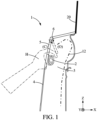
Fig. 1 is a schematic side view of a gripping system according to a first embodiment, -
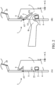
Fig. 2 is a schematic side view of a gripping system according to a second embodiment, -
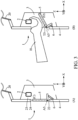
Fig. 3 is a schematic side view of a gripping system according to a third embodiment, -
Fig. 4 is a schematic view of a gripping system according to a fourth embodiment, -
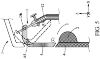
Fig. 5 is a schematic side view of a gripping system according to a fifth embodiment, -
Fig. 6 is another schematic side view of the gripping system offigure 5 , -
Fig. 7 is a schematic side view of a gripping system according to a sixth embodiment, -
Fig. 8 is a general view of a heavy-duty vehicle on which a gripping system according to the invention is implemented, -
Fig. 9 is a general view of the heavy-duty vehicle offigure 7 while the gripping system is in use. - In order to make the figures easier to read, the various elements are not necessarily represented to scale. In these figures, identical elements receive the same reference number. Certain elements or parameters can be indexed, ie designated for example by first element or second element, or first parameter and second parameter, etc. The purpose of this indexing is to differentiate elements or parameters that are similar, but not identical. This indexing does not imply the priority of one element, or one parameter over another, and names can be interchanged. When it is mentioned that a subsystem comprises a given element, the presence of other elements in this subsystem is not excluded.
- It is now referred to
figure 8. Figure 8 illustrates anindustrial vehicle 100 comprising agripping system 1 according to the invention. On the illustrated example, theindustrial vehicle 100 is a truck. According to not represented examples, the industrial vehicle can be a dump truck, or a bus. - The present invention relates to a
gripping system 1 for helping a user climbing over a substantiallyvertical surface 50 of anindustrial vehicle 100, the grippingsystem 1 comprising : - a
grip member 2 configured for being installed in a recessedarea 3 of abodywork element 4, - a
closure member 5 movable between :- A first position C in which the
closure member 5 closes the recessedarea 3, and - A second position O in which the recessed
area 3 is opened so that thegrip member 2 can be grasped,
- A first position C in which the
- Within the context of the present disclosure, substantially vertical means that the
surface 50 to climb over is vertical or close to vertical, depending on the exact shape of the bodywork of the industrial vehicle. Thesurface 50 forms an angle higher than 70° with the surface of the road on which the industrial vehicle is driven. When an operator wants to work over thesurface 50 of the vehicle, for example for cleaning thewindscreen 20, he needs to hoist himself up along thesurface 50 of thevehicle 100. Agripping system 1 provides a strong support to keep one's balance and reduce the risk of fall and resulting injuries. Thegripping system 1 is also called a hand holding system, or a hand support system. - The
grip member 2 is housed in a recessedarea 3 which can be closed by aclosure member 5. The recessedarea 3 forms a cavity. This cavity is not necessarily closed. The bottom of the cavity may comprise holes to ensure drainage of rainwater or possible condensation of humidity. Theclosure member 5 of the recessed area is for example a flap. When thegrip member 2 is not in use, it doesn't protrude from the external surface of the cabin of the vehicle. No aerodynamic disturbances are generated by thegrip member 2. Drag coefficient is therefore reduced, and aerodynamic noises are eliminated, or at least largely reduced. When a user needs to use thegrip member 2 for climbing over thesurface 50 of the vehicle, he just has to push theclosure member 5 open to access thegrip member 2 and grab it. Vehicle efficiency is optimized without compromising ease of use. In all embodiments, theclosure member 5 may always be pushed by the user. In some embodiments, theclosure member 5 can be moved as well by other means which can provide an automatic actuation of the closure member, as it will described in detail later. - When the
closure member 5 is in the first position C, it blocks the access to thegrip member 2. The first position C is called blocking position. Thegrip member 2 is concealed when theclosure member 5 is in the first position C. The first position C is also called concealed position. - The
grip member 2 is accessible when theclosure member 5 is in the second position O. In other words, a user can grasp thegrip member 2 so that he can climb over thevertical surface 50 by supporting at least a fraction of his weight on thegrip member 2. The second position O is said revealing position. The user can secure its standing position; improving its safety while working along the substantially vertical surface of the industrial vehicle. - The
closure member 5 should be large enough to provide access from various angles of approach of the forearm of the user. Theclosure member 5 is for example 20 centimeters wide and 10 centimeters high. Theclosure member 5 may be a metal sheet. Theclosure member 5 may be a plastic injected part. Theclosure member 5 may be the same color as the neighboring bodywork for better integration. - The
closure member 5 is for example rectangular. Any shape is possible, as long as it is adapted to the passage of a hand and wrist of the users, and as long as theclosure member 5 can be moved from the blocking position C to the revealing position O without interfering with other elements. - According to one aspect of the invention, the
closure member 5 is configured to be flush with thebodywork element 4 when theclosure member 5 is in the first position C. Therefore, the shape of the bodywork can be smooth and sleek when thegrip member 2 is not in use. When thetruck 100 is running, the aerodynamic drag of thetruck 100 is not compromised by the presence of thegrip member 2. - According to another aspect of the invention, the gripping system comprises an
elastic spring 6 configured to deform when theclosure member 5 is moved from the first position C to the second position O. In other words, theclosure member 5 is moved from the first position C to the second position O against the action of anelastic spring 6. Theelastic spring 6 brings back theclosure member 5 in the first position C when the user releases his grip on thegrip member 2. Therefore, theclosure member 5 comes back into the first position once a user removes his hand from thegripping system 1. - In an embodiment of the gripping system, the
elastic spring 6 is preloaded so that a minimal force to be exerted to move theclosure member 5 from the first position C to the second position O is higher than a predetermined threshold Th. - The
elastic spring 6 is preloaded, or pre-stressed, so that it tends to press theclosure member 5 against an end-stop that defines the position of theclosure member 5 when it is in the first position C. Theelastic spring 6 prevents theclosure member 5 from moving from the first position C to the second position O when the user exerts no action on theclosure member 5. The elastic spring preload is designed so that theclosure member 5 doesn't move under the action of the aerodynamic pressure or under the action of road vibrations, ensuring that theclosure member 5 remains firmly in the first position C when thegripping system 1 is not in use. The efficiency of the device is maintained even the vehicle travels at maximum speed with wind opposite to travelling direction, and possible rattling noises ofclosure member 5 oscillations are avoided. - In one embodiment, illustrated for example on
figure 2 , theelastic spring 6 is an helical spring. Theelastic spring 6 can be compressed when theclosure member 5 is moved from the first position C to the second position O. In a variant, theelastic spring 6 can be stretched when theclosure member 5 is moved from the first position C to the second position O. - In the illustrated embodiments of the
gripping system 1, theclosure member 5 is rotatable along a rotation axis A5. - In a first embodiment illustrated on
figure 1 , theelastic spring 6 is a torsion spring. The torsion spring is coaxial with a rotation axis A5 of theclosure member 5. - In the illustrated embodiments, the
closure member 5 is rotatable around a rotation axis A5, and the rotation axis A5 of theclosure member 5 is horizontal when thegripping system 1 is orientated in the nominal installation position in theindustrial vehicle 100. What is called nominal installation position in theindustrial vehicle 100 is the position when thegripping system 1 is fully assembled on a vehicle, with the vehicle rolling on a horizontal road. In other words, the axis of the rotation of theclosure member 5 is parallel to the plane defined by a longitudinal axis X and a transverse axis Y of the industrial vehicle. The longitudinal axis X is by definition the front-rear axis of the vehicle, and the transverse axis Y is the left-right axis. Similarly, the top edge and bottom edge of theclosure member 5, upwards and downward directions are defined when thegripping system 1 is orientated the same way as its nominal installation position in theindustrial vehicle 100. - In a different embodiment, which is not represented, the rotation axis of the
closure member 5 is vertical when thegripping system 1 is orientated in the nominal installation position. In other words, the rotation axis of theclosure member 5 is in this case perpendicular to both the longitudinal axis X and the transverse axis Y of theindustrial vehicle 100. - According to a second embodiment, represented on
figure 2 , thegrip member 2 is vertically located below abottom edge 22 of theclosure member 5. - In the represented embodiments, the
closure member 5 is moved inwards of the recessedarea 3 when theclosure member 5 is moved from the first position C to the second position O. Theshutter 5 is moved towards the interior of the recessedarea 3 when theclosure member 5 is rotated from the first position C to the second position O. Theclosure member 5 doesn't protrude out of the cabin body surface. - In the embodiments illustrated on
figure 1 andfigure 2 , theclosure member 5 is configured to swing upward when theclosure member 5 is moved from the first position C to the second position O. Theclosure member 5 is configured to swing away from thegrip member 2. The rotation axis A5 of theclosure member 5 is located near a top edge of theclosure member 5. - In a third embodiment, illustrated on
figure 3 , theclosure member 5 is configured to swing downward when theclosure member 5 is moved from the first position C to the second position O. The rotation axis A5 of theclosure member 5 is located near abottom edge 22 of theclosure member 5. On bothfigure 2 andfigure 3 , the part A of the figure represents thegripping system 1 with thegrip member 2 in the first position C. The part B of these figures represent thegripping system 1 with a hand H of a user in contact with thegrip member 2. - The
closure member 5 has an angular stroke T5 comprised between 70° and 110°. In other words, theclosure member 5 rotates by an angle T5 comprised between 70° and 110° when it is moved from the first position C to the second position O. - In the embodiments of the
gripping system 1 illustrated onfigure 1 to 3 , thegrip member 2 is a handle. Thegrip member 2 has an elongated shape, and aclearance 23 is left between this elongated shape and the facingwall 24. The user can encircle the elongated shape with his hand to get a strong support. The handle can be a metal sheet put into shape, like a steel sheet. The handle can also be an aluminum casting. - In another embodiment, illustrated on
figure 5 , thegrip member 2 is a grabbing pad. The grabbing pad forms a protrusion that the hand of the user can grab. The grabbingpad 2 can be a rubber block. The grabbing pad can also be an injected plastic part. - According to a fourth embodiment, the gripping
system 1 further comprises : - a
step 7 rotatable between a stowed position S and a deployed position D, - a
locking mechanism 16 configured to block theclosure member 5 when thestep 7 is in the stowed position S, and configured to release theclosure member 5 when thestep 7 is in the deployed position D. - The
rotatable step 7, illustrated onfigure 9 , is configured for providing a bearing surface on which a user U can lean when thestep 7 is in the deployed position D. In other words, thestep 7 protrudes from the front of thetruck 100 when thestep 7 is in the deployed position D. Thestep 7 can be deployed by a user when he needs to climb, and put back in stowed position when it's not needed any more The user U can hoist himself up along the substantiallyvertical surface 50 of thetruck 100 by placing one foot on the deployedstep 7 and grabbing at the same time thegrip member 2 with one hand H to support his weight and improve his balance. He can then with his free hand perform a task such as washing thewindscreen 20 of the truck 100.Therotatable step 7 is optional. A fixed step, or set of fixed steps, located on the side of the truck to assist the driver or the passenger in getting into the cabin, may also be used to gain access to the gripping system 1.When thestep 7 is in stowed position S, it remains within the external boundaries of the bodywork of the truck. There's no protrusion of thestep 7 when it is in the stowed position S. Onfigure 9 , the stowed position S of thestep 7 is represented with a dotted line and the deployed position D is represented with a plain line. - The
locking mechanism 16 is illustrated onfigure 4 . Thelocking mechanism 16 comprises a lockingpin 17 configured to be inserted in abore 18 of theclosure member 5. The lockingpin 17 can have a translation motion along an axis A17. - The
locking mechanism 16 comprises acable 19 linking thestep 7 and the lockingpin 17. Afirst end 19a of the linkingcable 19 is fixed to thestep 7 and asecond end 19b of thecable 19 is fixed to the lockingpin 17. Onfigure 4 , thecable 19 is represented in two separated portions only for clarity. When thestep 7 is in the stowed position S, the lockingpin 17 rests inserted in thebore 18 of theclosure member 5. Theclosure member 5 can't be moved even if the user tries to push it open. When thestep 7 is moved from the stowed position S to the deployed position D, thecable 19 pulls the lockingpin 17 out of thebore 18, thus releasing theclosure member 5. Theclosure member 5 may then be moved. Part A offigure 4 is a side view, and part B offigure 4 is a front view. Other kinds of locking mechanism can also be used, with for example a rotating blocking element. - A fifth and a sixth embodiment provide automated opening of the
closure member 5. - For this, the gripping
system 1 further comprises : - a
step 7 rotatable between a stowed position S and a deployed position D, - an
actuation device 11 configured for moving theclosure member 5 from the first position C to the second position O when therotatable step 7 is moved from the stowed position S to the deployed position D. - In this configuration, deploying the
step 7 automatically moves theclosure member 5 so that thegrip member 2 is readily available. The user doesn't have to push theclosure member 5 opened to access thegrip member 2. - Different actuation devices can be implemented. In the fifth embodiment, illustrated on
figure 5 andfigure 6 , theactuation device 11 comprises acable 12 linking theclosure member 5 and thestep 7. Afirst end 12a of the linkingcable 12 is fixed to thestep 7 and asecond end 12b of thecable 12 is fixed to theclosure member 5. - The
step 7 is horizontally hinged, as represented onfigure 6 andfigure 9 . Thefirst end 12a of thecable 12 is distant from the rotation axis A7 of thestep 7. The axis of rotation A7 of thestep 7 is here parallel to a transverse axis Y of the truck. Thesecond end 12b of thecable 12 is distant from the rotation axis A5 of theclosure member 5. When thestep 7 is moved from the stowed position S to the deployed position D, thecable 12 pushes theclosure member 5 opened against the action of the return spring 6.When thestep 7 is moved back from the deployed position D to the stowed position S, thecable 12 doesn't push theclosure member 5 anymore and thereturn spring 6 brings theclosure member 5 back into the first position C. The return spring has not been represented onfigure 5 and6 . In a non-represented variant, an axis of rotation A7 of thestep 7 is parallel to a longitudinal axis X of the truck. - In the sixth embodiment, illustrated on
figure 7 , the gripping system comprises aposition sensor 13 configured for detecting a position of thestep 7, and theactuation device 11 comprises anelectric motor 14 and atransmission mechanism 15 configured to move theclosure member 5 from the first position C to the second position O when thestep 7 is in the deployed position D. - The
position sensor 13 is configured for detecting transitions between the stowed position S of thestep 7 and the deployed position D of thestep 7. Theactuation device 11 is activated to move theclosure member 5 from the first position C to the second position O when a transition from the stowed position S of thestep 7 to the deployed position D of thestep 7 is detected. For this, anelectronic control unit 25 receives the different signals and activates or deactivates theelectric motor 14 in order to control theactuation device 11 and the position of theclosure member 5. - The
position sensor 13 can be a switch. In this case, the output signal can only take two different values. In short, theposition sensor 13 can only detect two different positions. Theposition sensor 13 can also deliver a continuous information. Output signal can vary continuously across a range defined by a minimum position and a maximum position. Theposition sensor 13 can for example be a Hall sensor associated with a magnetic target fixed to thestep 7. - The
electric motor 14 and thetransmission mechanism 15 are configured to move theclosure member 5 from the second position O to the first position C when thestep 7 is in the stowed position S. Theactuation device 11 is activated to move theclosure member 5 from the second position O to the first position C when a transition from the deployed position D of thestep 7 and the stowed position S of thestep 7 is detected. - The
closure member 5 is opened only when thestep 7 is in the deployed position D. In short, theclosure member 5 is opened only when thegripping system 1 is likely to be used. - According to an implementation of the gripping system, the
transmission mechanism 15 comprises a gear train. The gear train may comprise a worm-screw which drives a gear. - In the sixth embodiment, the gripping system further comprises a
safety switch 21 configured to deactivate theactuation device 11. The role of thesafety switch 21 is to prevent theclosure member 5 to be moved in the second position O in which the recessedarea 3 is opened whereas the safety conditions are not met. In that case, theclosure member 5 has to remain in the first position C in which the closure member closes the recessedarea 3. Therefore, the grippingmember 2 remains unusable as long as the safety conditions are not met. - The
truck 100 comprises an ignition key with two stable positions. A first stable position is a powered-down position in which the various electric systems of the truck are deactivated. A second stable position is a powered-up position in which the various electric systems of the truck are activated. The second position is the position in which the truck is driven. - The
safety switch 21 is configured to deactivate theactuation device 11 when the ignition key of the truck is in the powered-up position. Thesafety switch 21 prevents theactuation device 11 to move theclosure member 2 in the second position O when the ignition key of the truck is in the powered-up position. Theclosure member 5 thus remains in the closed position C when the ignition key is on. The risk of having someone starting to climb over thevertical surface 50 of thetruck 100 while thetruck 100 is ready to be driven is eliminated. The hazardous situation is avoided. - In the illustrated embodiments, the
bodywork element 4 in which thegrip member 2 is installed is a front surface of thetruck 100. Thegrip member 2 may extend transversely along the full width of thetruck 100. - The
truck 100 may comprise at least two gripping systems as described earlier, the gripping systems being disposed at different locations of thetruck 100. The user can get support for various work positions in front of thewindscreen 20 of thetruck 100. - The
truck 100 may comprise at least two gripping systems as described earlier. The gripping systems are disposed at different locations of thetruck 100. The user can get support for various work positions in front of thewindscreen 20 of thetruck 100. - The at least two gripping systems may have a
common closure member 5. In other words, the at least two gripping systems haveindividual grip members 2 and share acommon closure member 5. - The at least two gripping systems may be independent. In other words, each gripping system has its
own closure member 5 and its own associatedgrip member 2.
Claims (15)
- A gripping system (1) for helping a user climbing over a substantially vertical surface (50) of an industrial vehicle (100), the gripping system (1) comprising:- a grip member (2) configured for being installed in a recessed area (3) of a bodywork element (4),- a closure member (5) movable between :- A first position (C) in which the closure member (5) closes the recessed area (3), and- A second position (O) in which the closure member (3) is opened so that the grip member (2) can be grasped,in which the closure member (5) is configured for moving from the first position (C) to the second position (O) at least under a pushing action of the user.
- The gripping system (1) according to claim 1, in which the closure member (5) is configured to be flush with the bodywork element (4) when the closure member (5) is in the first position (C).
- The gripping system (1) according to claim 1 or 2, comprising an elastic spring (6) configured to deform when the closure member (5) is moved from the first position (C) to the second position (O).
- The gripping system (1) according to the preceding claim, in which the elastic spring (6) is preloaded so that a minimal force to be exerted to move the closure member (5) from the first position (C) to the second position (O) is higher than a predetermined threshold (Th).
- The gripping system (1) according to any of the preceding claims, in which the closure member (5) is rotatable along a rotation axis (A5).
- The gripping system (1) according to any of the preceding claims, in which the closure member (5) is rotatable around a rotation axis (A5), and in which the rotation axis (A5) of the closure member (5) is horizontal when the gripping system (1) is orientated in a nominal installation position in the industrial vehicle (100).
- The gripping system (1) according to any of the preceding claims, in which the grip member (2) is a handle.
- The gripping system (1) according to any of the preceding claims, further comprising :- a step (7) rotatable between a stowed position (S) and a deployed position (D),- a locking mechanism (16) configured to block the closure member (5) when the step (7) is in the stowed position (S), and configured to release the closure member (5) when the step (7) is in the deployed position (D).
- The gripping system (1) according to any of the preceding claims, further comprising :- a step (7) rotatable between a stowed position (S) and a deployed position (D),- an actuation device (11) configured for moving the closure member (5) from the first position (C) to the second position (O) when the rotatable step (7) is moved from the stowed position (S) to the deployed position (D).
- The gripping system (1) according to the preceding claim, in which the actuation device (11) comprises a cable (12) linking the closure member (5) and the step (7).
- The gripping system (1) according to claim 8 or 9, comprising a position sensor (13) configured for detecting a position of the step (7), in which the actuation device (11) comprises an electric motor (14) and a transmission mechanism (15) configured to move the closure member (5) from the first position (C) to the second position (O) when the step (7) is in the deployed position (D).
- The gripping system (1) according to claim 11, comprising a safety switch (21) configured to deactivate the actuation device (11).
- The gripping system (1) according to claim 11 or 12, in which the transmission mechanism (15) comprises a gear train.
- A truck (100) comprising a gripping system (1) according to one of the preceding claims.
- A truck (100) according to the preceding claim, in which the bodywork element (4) in which the grip member (2) is installed is a front surface of the truck (100).
Priority Applications (3)
| Application Number | Priority Date | Filing Date | Title |
|---|---|---|---|
| EP21202224.8A EP4166394B1 (en) | 2021-10-12 | 2021-10-12 | Gripping system for an industrial vehicle |
| US17/960,364 US12485822B2 (en) | 2021-10-12 | 2022-10-05 | Gripping system for an industrial vehicle |
| CN202211245357.7A CN115959018A (en) | 2021-10-12 | 2022-10-12 | Gripping system for industrial vehicles |
Applications Claiming Priority (1)
| Application Number | Priority Date | Filing Date | Title |
|---|---|---|---|
| EP21202224.8A EP4166394B1 (en) | 2021-10-12 | 2021-10-12 | Gripping system for an industrial vehicle |
Publications (2)
| Publication Number | Publication Date |
|---|---|
| EP4166394A1 true EP4166394A1 (en) | 2023-04-19 |
| EP4166394B1 EP4166394B1 (en) | 2025-06-25 |
Family
ID=78134854
Family Applications (1)
| Application Number | Title | Priority Date | Filing Date |
|---|---|---|---|
| EP21202224.8A Active EP4166394B1 (en) | 2021-10-12 | 2021-10-12 | Gripping system for an industrial vehicle |
Country Status (3)
| Country | Link |
|---|---|
| US (1) | US12485822B2 (en) |
| EP (1) | EP4166394B1 (en) |
| CN (1) | CN115959018A (en) |
Citations (1)
| Publication number | Priority date | Publication date | Assignee | Title |
|---|---|---|---|---|
| DE102018004019A1 (en) * | 2018-05-18 | 2018-12-06 | Daimler Ag | Arrangement of at least one handle on a front of a cab for a commercial vehicle |
Family Cites Families (18)
| Publication number | Priority date | Publication date | Assignee | Title |
|---|---|---|---|---|
| US3171671A (en) * | 1963-07-18 | 1965-03-02 | Clinton W Cornett | Step for vehicle |
| US3883844A (en) * | 1974-02-25 | 1975-05-13 | Ii George F Wood | Signal means for vehicle retractable step |
| US3971456A (en) * | 1975-04-10 | 1976-07-27 | Yonce Everett R | Handle-rung module |
| US3986503A (en) * | 1975-09-22 | 1976-10-19 | Caterpillar Tractor Co. | Mounting means for machines |
| US4750753A (en) * | 1984-08-15 | 1988-06-14 | Dezern Morris L | Bumper mounted folding step assembly |
| US5566962A (en) * | 1994-10-14 | 1996-10-22 | Burnham; Roy | Truck step guard |
| US5538265A (en) * | 1995-01-12 | 1996-07-23 | Navistar International Transportation Corp. | Retractable step for a truck |
| JPH08216758A (en) * | 1995-02-14 | 1996-08-27 | Showa Aircraft Ind Co Ltd | Vehicle outer grip mounting structure |
| SE517908C2 (en) * | 2000-04-11 | 2002-07-30 | Volvo Articulated Haulers Ab | engine housing |
| US8943752B2 (en) * | 2007-01-05 | 2015-02-03 | Ford Global Technologies, Llc | Door handle system for an automotive vehicle |
| GB2445534A (en) * | 2007-01-09 | 2008-07-16 | Anton Manning | A free standing wheeled bin docking station incorporating a bin lid opener which is operated by a foot pedal |
| DE102007039804A1 (en) * | 2007-08-23 | 2009-02-26 | GM Global Technology Operations, Inc., Detroit | Gripping system for body part e.g. rear flap, of motor vehicle, has grip attached to body part, where gripping surface of grip is exposed for user at outer surface of body part in actuating position and covered in resting position |
| CN201771266U (en) * | 2010-08-24 | 2011-03-23 | 浙江吉利汽车研究院有限公司 | Novel automobile door handle structure for automobile |
| US8443553B1 (en) * | 2011-11-23 | 2013-05-21 | GM Global Technology Operations LLC | Closure assembly with moveable cover and closeout for a retractable handle |
| KR101316381B1 (en) * | 2011-12-14 | 2013-10-08 | 현대자동차주식회사 | Bumper step for heavy-duty truck |
| CN202518138U (en) * | 2012-02-09 | 2012-11-07 | 李建鑫 | Bus handrail |
| US20180290596A1 (en) * | 2017-04-11 | 2018-10-11 | GM Global Technology Operations LLC | Extendable articulating ladder |
| US10562456B2 (en) * | 2018-06-29 | 2020-02-18 | Toyota Motor Engineering & Manufacturing North America, Inc. | Front bumper slide-out step |
-
2021
- 2021-10-12 EP EP21202224.8A patent/EP4166394B1/en active Active
-
2022
- 2022-10-05 US US17/960,364 patent/US12485822B2/en active Active
- 2022-10-12 CN CN202211245357.7A patent/CN115959018A/en active Pending
Patent Citations (1)
| Publication number | Priority date | Publication date | Assignee | Title |
|---|---|---|---|---|
| DE102018004019A1 (en) * | 2018-05-18 | 2018-12-06 | Daimler Ag | Arrangement of at least one handle on a front of a cab for a commercial vehicle |
Also Published As
| Publication number | Publication date |
|---|---|
| CN115959018A (en) | 2023-04-14 |
| US12485822B2 (en) | 2025-12-02 |
| EP4166394B1 (en) | 2025-06-25 |
| US20230114629A1 (en) | 2023-04-13 |
Similar Documents
| Publication | Publication Date | Title |
|---|---|---|
| US8028375B2 (en) | Pinch prevention structure of slide door | |
| FR2826998B1 (en) | DOOR HANDLE EQUIPPED WITH AUTOMATIC RETRACTABLE PORTILLON | |
| JPH1086862A (en) | Luggage board structure for automobiles | |
| CN113027257A (en) | Vehicle power closure handle assembly and power closure actuation method | |
| JP2018510984A (en) | Automotive latch | |
| US8346467B2 (en) | Device for detecting an event in a vehicle or in the surrounds of a vehicle | |
| US4434919A (en) | Multiple-position spare tire mount | |
| US6137404A (en) | Method and apparatus for preventing entrapment by a vehicle closure | |
| EP4166394B1 (en) | Gripping system for an industrial vehicle | |
| CN115199158A (en) | Mechanical emergency latch release system and method for vehicle door | |
| KR102829945B1 (en) | Method for determining driver intent | |
| KR101915582B1 (en) | Apparatus for Opening and closing door of special purpose truck | |
| JP2009535534A (en) | Vehicle entrance system | |
| KR100383982B1 (en) | cabin tilting device for truck | |
| EP3342610B1 (en) | Tailgate for a vehicle | |
| JP2003089362A (en) | Car hood structure | |
| EP0808981B1 (en) | A device for controlling the opening and closing of a motor vehicle door | |
| JP2004027824A (en) | In-vehicle door operation system | |
| JPS6317719Y2 (en) | ||
| JP4398074B2 (en) | Automatic sliding door opening and closing system | |
| JPH0422727B2 (en) | ||
| EP0847892A3 (en) | Vehicle seat position detection system | |
| JP2005113618A (en) | Vehicle door lock device | |
| CN121469433A (en) | An integrated flip electric pedal | |
| JPH0134589Y2 (en) |
Legal Events
| Date | Code | Title | Description |
|---|---|---|---|
| PUAI | Public reference made under article 153(3) epc to a published international application that has entered the european phase |
Free format text: ORIGINAL CODE: 0009012 |
|
| STAA | Information on the status of an ep patent application or granted ep patent |
Free format text: STATUS: THE APPLICATION HAS BEEN PUBLISHED |
|
| AK | Designated contracting states |
Kind code of ref document: A1 Designated state(s): AL AT BE BG CH CY CZ DE DK EE ES FI FR GB GR HR HU IE IS IT LI LT LU LV MC MK MT NL NO PL PT RO RS SE SI SK SM TR |
|
| STAA | Information on the status of an ep patent application or granted ep patent |
Free format text: STATUS: REQUEST FOR EXAMINATION WAS MADE |
|
| 17P | Request for examination filed |
Effective date: 20231019 |
|
| RBV | Designated contracting states (corrected) |
Designated state(s): AL AT BE BG CH CY CZ DE DK EE ES FI FR GB GR HR HU IE IS IT LI LT LU LV MC MK MT NL NO PL PT RO RS SE SI SK SM TR |
|
| GRAP | Despatch of communication of intention to grant a patent |
Free format text: ORIGINAL CODE: EPIDOSNIGR1 |
|
| STAA | Information on the status of an ep patent application or granted ep patent |
Free format text: STATUS: GRANT OF PATENT IS INTENDED |
|
| INTG | Intention to grant announced |
Effective date: 20250116 |
|
| GRAS | Grant fee paid |
Free format text: ORIGINAL CODE: EPIDOSNIGR3 |
|
| GRAA | (expected) grant |
Free format text: ORIGINAL CODE: 0009210 |
|
| STAA | Information on the status of an ep patent application or granted ep patent |
Free format text: STATUS: THE PATENT HAS BEEN GRANTED |
|
| AK | Designated contracting states |
Kind code of ref document: B1 Designated state(s): AL AT BE BG CH CY CZ DE DK EE ES FI FR GB GR HR HU IE IS IT LI LT LU LV MC MK MT NL NO PL PT RO RS SE SI SK SM TR |
|
| REG | Reference to a national code |
Ref country code: GB Ref legal event code: FG4D |
|
| REG | Reference to a national code |
Ref country code: CH Ref legal event code: EP |
|
| REG | Reference to a national code |
Ref country code: CH Ref legal event code: EP |
|
| REG | Reference to a national code |
Ref country code: IE Ref legal event code: FG4D |
|
| REG | Reference to a national code |
Ref country code: DE Ref legal event code: R096 Ref document number: 602021032743 Country of ref document: DE |
|
| PG25 | Lapsed in a contracting state [announced via postgrant information from national office to epo] |
Ref country code: FI Free format text: LAPSE BECAUSE OF FAILURE TO SUBMIT A TRANSLATION OF THE DESCRIPTION OR TO PAY THE FEE WITHIN THE PRESCRIBED TIME-LIMIT Effective date: 20250625 |
|
| REG | Reference to a national code |
Ref country code: LT Ref legal event code: MG9D |
|
| PG25 | Lapsed in a contracting state [announced via postgrant information from national office to epo] |
Ref country code: NO Free format text: LAPSE BECAUSE OF FAILURE TO SUBMIT A TRANSLATION OF THE DESCRIPTION OR TO PAY THE FEE WITHIN THE PRESCRIBED TIME-LIMIT Effective date: 20250925 Ref country code: GR Free format text: LAPSE BECAUSE OF FAILURE TO SUBMIT A TRANSLATION OF THE DESCRIPTION OR TO PAY THE FEE WITHIN THE PRESCRIBED TIME-LIMIT Effective date: 20250926 |
|
| PG25 | Lapsed in a contracting state [announced via postgrant information from national office to epo] |
Ref country code: BG Free format text: LAPSE BECAUSE OF FAILURE TO SUBMIT A TRANSLATION OF THE DESCRIPTION OR TO PAY THE FEE WITHIN THE PRESCRIBED TIME-LIMIT Effective date: 20250625 |
|
| PG25 | Lapsed in a contracting state [announced via postgrant information from national office to epo] |
Ref country code: HR Free format text: LAPSE BECAUSE OF FAILURE TO SUBMIT A TRANSLATION OF THE DESCRIPTION OR TO PAY THE FEE WITHIN THE PRESCRIBED TIME-LIMIT Effective date: 20250625 |
|
| PG25 | Lapsed in a contracting state [announced via postgrant information from national office to epo] |
Ref country code: RS Free format text: LAPSE BECAUSE OF FAILURE TO SUBMIT A TRANSLATION OF THE DESCRIPTION OR TO PAY THE FEE WITHIN THE PRESCRIBED TIME-LIMIT Effective date: 20250925 |
|
| PG25 | Lapsed in a contracting state [announced via postgrant information from national office to epo] |
Ref country code: LV Free format text: LAPSE BECAUSE OF FAILURE TO SUBMIT A TRANSLATION OF THE DESCRIPTION OR TO PAY THE FEE WITHIN THE PRESCRIBED TIME-LIMIT Effective date: 20250625 |
|
| REG | Reference to a national code |
Ref country code: NL Ref legal event code: MP Effective date: 20250625 |
|
| PG25 | Lapsed in a contracting state [announced via postgrant information from national office to epo] |
Ref country code: NL Free format text: LAPSE BECAUSE OF FAILURE TO SUBMIT A TRANSLATION OF THE DESCRIPTION OR TO PAY THE FEE WITHIN THE PRESCRIBED TIME-LIMIT Effective date: 20250625 |
|
| PG25 | Lapsed in a contracting state [announced via postgrant information from national office to epo] |
Ref country code: PT Free format text: LAPSE BECAUSE OF FAILURE TO SUBMIT A TRANSLATION OF THE DESCRIPTION OR TO PAY THE FEE WITHIN THE PRESCRIBED TIME-LIMIT Effective date: 20251027 |
|
| REG | Reference to a national code |
Ref country code: AT Ref legal event code: MK05 Ref document number: 1806164 Country of ref document: AT Kind code of ref document: T Effective date: 20250625 |
|
| PG25 | Lapsed in a contracting state [announced via postgrant information from national office to epo] |
Ref country code: IS Free format text: LAPSE BECAUSE OF FAILURE TO SUBMIT A TRANSLATION OF THE DESCRIPTION OR TO PAY THE FEE WITHIN THE PRESCRIBED TIME-LIMIT Effective date: 20251025 |
|
| PGFP | Annual fee paid to national office [announced via postgrant information from national office to epo] |
Ref country code: DE Payment date: 20251028 Year of fee payment: 5 |
|
| PG25 | Lapsed in a contracting state [announced via postgrant information from national office to epo] |
Ref country code: AT Free format text: LAPSE BECAUSE OF FAILURE TO SUBMIT A TRANSLATION OF THE DESCRIPTION OR TO PAY THE FEE WITHIN THE PRESCRIBED TIME-LIMIT Effective date: 20250625 Ref country code: SM Free format text: LAPSE BECAUSE OF FAILURE TO SUBMIT A TRANSLATION OF THE DESCRIPTION OR TO PAY THE FEE WITHIN THE PRESCRIBED TIME-LIMIT Effective date: 20250625 |
|
| PG25 | Lapsed in a contracting state [announced via postgrant information from national office to epo] |
Ref country code: CZ Free format text: LAPSE BECAUSE OF FAILURE TO SUBMIT A TRANSLATION OF THE DESCRIPTION OR TO PAY THE FEE WITHIN THE PRESCRIBED TIME-LIMIT Effective date: 20250625 |
|
| PG25 | Lapsed in a contracting state [announced via postgrant information from national office to epo] |
Ref country code: PL Free format text: LAPSE BECAUSE OF FAILURE TO SUBMIT A TRANSLATION OF THE DESCRIPTION OR TO PAY THE FEE WITHIN THE PRESCRIBED TIME-LIMIT Effective date: 20250625 |
|
| PG25 | Lapsed in a contracting state [announced via postgrant information from national office to epo] |
Ref country code: EE Free format text: LAPSE BECAUSE OF FAILURE TO SUBMIT A TRANSLATION OF THE DESCRIPTION OR TO PAY THE FEE WITHIN THE PRESCRIBED TIME-LIMIT Effective date: 20250625 |
|
| PG25 | Lapsed in a contracting state [announced via postgrant information from national office to epo] |
Ref country code: SK Free format text: LAPSE BECAUSE OF FAILURE TO SUBMIT A TRANSLATION OF THE DESCRIPTION OR TO PAY THE FEE WITHIN THE PRESCRIBED TIME-LIMIT Effective date: 20250625 |
|
| PG25 | Lapsed in a contracting state [announced via postgrant information from national office to epo] |
Ref country code: ES Free format text: LAPSE BECAUSE OF FAILURE TO SUBMIT A TRANSLATION OF THE DESCRIPTION OR TO PAY THE FEE WITHIN THE PRESCRIBED TIME-LIMIT Effective date: 20250625 |
|
| PG25 | Lapsed in a contracting state [announced via postgrant information from national office to epo] |
Ref country code: RO Free format text: LAPSE BECAUSE OF FAILURE TO SUBMIT A TRANSLATION OF THE DESCRIPTION OR TO PAY THE FEE WITHIN THE PRESCRIBED TIME-LIMIT Effective date: 20250625 |
|
| PG25 | Lapsed in a contracting state [announced via postgrant information from national office to epo] |
Ref country code: DK Free format text: LAPSE BECAUSE OF FAILURE TO SUBMIT A TRANSLATION OF THE DESCRIPTION OR TO PAY THE FEE WITHIN THE PRESCRIBED TIME-LIMIT Effective date: 20250625 |
|
| PG25 | Lapsed in a contracting state [announced via postgrant information from national office to epo] |
Ref country code: IT Free format text: LAPSE BECAUSE OF FAILURE TO SUBMIT A TRANSLATION OF THE DESCRIPTION OR TO PAY THE FEE WITHIN THE PRESCRIBED TIME-LIMIT Effective date: 20250625 |
|
| PLBE | No opposition filed within time limit |
Free format text: ORIGINAL CODE: 0009261 |
|
| STAA | Information on the status of an ep patent application or granted ep patent |
Free format text: STATUS: NO OPPOSITION FILED WITHIN TIME LIMIT |