EP4166392A1 - Cover unit and lighting mounting for vehicle - Google Patents
Cover unit and lighting mounting for vehicle Download PDFInfo
- Publication number
- EP4166392A1 EP4166392A1 EP21202331.1A EP21202331A EP4166392A1 EP 4166392 A1 EP4166392 A1 EP 4166392A1 EP 21202331 A EP21202331 A EP 21202331A EP 4166392 A1 EP4166392 A1 EP 4166392A1
- Authority
- EP
- European Patent Office
- Prior art keywords
- driving mechanism
- opening
- cover element
- axial end
- cover
- Prior art date
- Legal status (The legal status is an assumption and is not a legal conclusion. Google has not performed a legal analysis and makes no representation as to the accuracy of the status listed.)
- Granted
Links
Images



Classifications
-
- F—MECHANICAL ENGINEERING; LIGHTING; HEATING; WEAPONS; BLASTING
- F21—LIGHTING
- F21S—NON-PORTABLE LIGHTING DEVICES; SYSTEMS THEREOF; VEHICLE LIGHTING DEVICES SPECIALLY ADAPTED FOR VEHICLE EXTERIORS
- F21S41/00—Illuminating devices specially adapted for vehicle exteriors, e.g. headlamps
- F21S41/40—Illuminating devices specially adapted for vehicle exteriors, e.g. headlamps characterised by screens, non-reflecting members, light-shielding members or fixed shades
- F21S41/43—Illuminating devices specially adapted for vehicle exteriors, e.g. headlamps characterised by screens, non-reflecting members, light-shielding members or fixed shades characterised by the shape thereof
-
- B—PERFORMING OPERATIONS; TRANSPORTING
- B60—VEHICLES IN GENERAL
- B60Q—ARRANGEMENT OF SIGNALLING OR LIGHTING DEVICES, THE MOUNTING OR SUPPORTING THEREOF OR CIRCUITS THEREFOR, FOR VEHICLES IN GENERAL
- B60Q1/00—Arrangement of optical signalling or lighting devices, the mounting or supporting thereof or circuits therefor
- B60Q1/26—Arrangement of optical signalling or lighting devices, the mounting or supporting thereof or circuits therefor the devices being primarily intended to indicate the vehicle, or parts thereof, or to give signals, to other traffic
- B60Q1/2692—Arrangement of optical signalling or lighting devices, the mounting or supporting thereof or circuits therefor the devices being primarily intended to indicate the vehicle, or parts thereof, or to give signals, to other traffic retractable lights
-
- B—PERFORMING OPERATIONS; TRANSPORTING
- B60—VEHICLES IN GENERAL
- B60Q—ARRANGEMENT OF SIGNALLING OR LIGHTING DEVICES, THE MOUNTING OR SUPPORTING THEREOF OR CIRCUITS THEREFOR, FOR VEHICLES IN GENERAL
- B60Q1/00—Arrangement of optical signalling or lighting devices, the mounting or supporting thereof or circuits therefor
- B60Q1/02—Arrangement of optical signalling or lighting devices, the mounting or supporting thereof or circuits therefor the devices being primarily intended to illuminate the way ahead or to illuminate other areas of way or environments
- B60Q1/04—Arrangement of optical signalling or lighting devices, the mounting or supporting thereof or circuits therefor the devices being primarily intended to illuminate the way ahead or to illuminate other areas of way or environments the devices being headlights
- B60Q1/05—Arrangement of optical signalling or lighting devices, the mounting or supporting thereof or circuits therefor the devices being primarily intended to illuminate the way ahead or to illuminate other areas of way or environments the devices being headlights retractable
-
- F—MECHANICAL ENGINEERING; LIGHTING; HEATING; WEAPONS; BLASTING
- F16—ENGINEERING ELEMENTS AND UNITS; GENERAL MEASURES FOR PRODUCING AND MAINTAINING EFFECTIVE FUNCTIONING OF MACHINES OR INSTALLATIONS; THERMAL INSULATION IN GENERAL
- F16C—SHAFTS; FLEXIBLE SHAFTS; ELEMENTS OR CRANKSHAFT MECHANISMS; ROTARY BODIES OTHER THAN GEARING ELEMENTS; BEARINGS
- F16C11/00—Pivots; Pivotal connections
- F16C11/04—Pivotal connections
- F16C11/045—Pivotal connections with at least a pair of arms pivoting relatively to at least one other arm, all arms being mounted on one pin
-
- F—MECHANICAL ENGINEERING; LIGHTING; HEATING; WEAPONS; BLASTING
- F16—ENGINEERING ELEMENTS AND UNITS; GENERAL MEASURES FOR PRODUCING AND MAINTAINING EFFECTIVE FUNCTIONING OF MACHINES OR INSTALLATIONS; THERMAL INSULATION IN GENERAL
- F16C—SHAFTS; FLEXIBLE SHAFTS; ELEMENTS OR CRANKSHAFT MECHANISMS; ROTARY BODIES OTHER THAN GEARING ELEMENTS; BEARINGS
- F16C31/00—Bearings for parts which both rotate and move linearly
- F16C31/02—Sliding-contact bearings
-
- F—MECHANICAL ENGINEERING; LIGHTING; HEATING; WEAPONS; BLASTING
- F21—LIGHTING
- F21S—NON-PORTABLE LIGHTING DEVICES; SYSTEMS THEREOF; VEHICLE LIGHTING DEVICES SPECIALLY ADAPTED FOR VEHICLE EXTERIORS
- F21S41/00—Illuminating devices specially adapted for vehicle exteriors, e.g. headlamps
- F21S41/40—Illuminating devices specially adapted for vehicle exteriors, e.g. headlamps characterised by screens, non-reflecting members, light-shielding members or fixed shades
- F21S41/47—Attachment thereof
-
- B—PERFORMING OPERATIONS; TRANSPORTING
- B60—VEHICLES IN GENERAL
- B60Q—ARRANGEMENT OF SIGNALLING OR LIGHTING DEVICES, THE MOUNTING OR SUPPORTING THEREOF OR CIRCUITS THEREFOR, FOR VEHICLES IN GENERAL
- B60Q1/00—Arrangement of optical signalling or lighting devices, the mounting or supporting thereof or circuits therefor
- B60Q1/0005—Devices preventing the lights from becoming dirty or damaged, e.g. protection grids or cleaning by air flow
-
- F—MECHANICAL ENGINEERING; LIGHTING; HEATING; WEAPONS; BLASTING
- F16—ENGINEERING ELEMENTS AND UNITS; GENERAL MEASURES FOR PRODUCING AND MAINTAINING EFFECTIVE FUNCTIONING OF MACHINES OR INSTALLATIONS; THERMAL INSULATION IN GENERAL
- F16C—SHAFTS; FLEXIBLE SHAFTS; ELEMENTS OR CRANKSHAFT MECHANISMS; ROTARY BODIES OTHER THAN GEARING ELEMENTS; BEARINGS
- F16C11/00—Pivots; Pivotal connections
- F16C11/02—Trunnions; Crank-pins
-
- F—MECHANICAL ENGINEERING; LIGHTING; HEATING; WEAPONS; BLASTING
- F16—ENGINEERING ELEMENTS AND UNITS; GENERAL MEASURES FOR PRODUCING AND MAINTAINING EFFECTIVE FUNCTIONING OF MACHINES OR INSTALLATIONS; THERMAL INSULATION IN GENERAL
- F16C—SHAFTS; FLEXIBLE SHAFTS; ELEMENTS OR CRANKSHAFT MECHANISMS; ROTARY BODIES OTHER THAN GEARING ELEMENTS; BEARINGS
- F16C2326/00—Articles relating to transporting
- F16C2326/01—Parts of vehicles in general
Definitions
- the present disclosure relates to a cover unit for selectively covering or exposing an opening in a structure, and a lighting mounting for a vehicle.
- Shutters or cover units for covering lights of a vehicle are well known.
- the cover units are configured to cover or reveal the light by performing a pivoting motion.
- cover units e.g. cover units comprising one cover element or cover units comprising two cover elements.
- the one cover element usually performs an opening movement similar to an opening garage door.
- the two cover elements are arranged parallel to each other in a closed position and during the opening and/or closing movement. Usually, the two cover elements contact each other substantially half way, and are moving away from each other during the opening movement, and towards each other during the closing movement.
- a cover unit for selectively covering or exposing an opening in a structure.
- the cover unit comprises at least a first cover element for covering or exposing the opening at least partly, wherein the first cover element has a first SE:FG axial end being coupled to a first driving mechanism, and a second axial end being coupled to a second driving mechanism.
- the first driving mechanism and the second driving mechanism are configured to move the first cover element between a closed position and an opened position.
- Each of the first driving mechanism and the second driving mechanism is controlled individually, and comprises an arm being configured to be rotatively coupled to the structure, at least one drive unit being configured to drive a movement of the arm, and a joint being configured to couple the arm to the respective axial end of the first cover element, and being configured to allow a two-axis rotation and one linear axis movement. Further, the joint is configured to allow the first axial end and the second axial end of the first cover element being moved differently during an opening movement for exposing the opening and/or a closing movement for covering the opening.
- Allowing the first axial end and the second axial end of the first cover element to be moved differently means that the first axial end and the second axial end may be moved different distances. This may allow more freedom to move and/or an increased range of motion. Thereby, a plurality of shapes can be covered or exposed by the cover unit, such as a rectangular shape, but also such as a triangular shape, a tapered shape and/or a trapezoidal shape. This may provide the adaptability to match various different shapes of openings, particularly modern design openings.
- the joint of each of the first driving mechanism and the second driving mechanism may allow compensating for a length difference between the first axial end and the second axial end, when they are moved different distances.
- each of the first driving mechanism and the second driving mechanism may allow a linear movement as well as a rotating movement of the respective axial end, and thus, of the first cover element, during the opening and/or closing movement. This allows achieving a reduced required space for the opening and/or closing movement of the first cover element.
- the cover unit allows adapting to a contour of the opening, which results in a reduced required installation space. Further, the cover unit allows following an exterior contour of the opening in a closed as well as in an open position.
- the cover unit may additionally comprise a second cover element, which has a first axial end being coupled to a third driving mechanism, and a second axial end being coupled to a fourth driving mechanism.
- the third driving mechanism and the fourth driving mechanism may be configured to move the second cover element between a closed position and an opened position.
- Each of the third driving mechanism and the fourth driving mechanism may be controlled individually, and may comprise an arm being configured to be rotatively coupled to the structure, at least one drive unit being configured to drive a movement of the arm, and a joint being configured to couple the arm to the respective axial end of the first cover element, and being configured to allow a two-axis rotation and one linear axis movement.
- the joint may be configured to allow the first axial end and the second axial end of the first cover element being moved differently during an opening movement for exposing the opening and/or a closing movement for covering the opening.
- the first cover element and the second cover element may be configured to contact each other in the closed position along a contact line to cover the opening, and/or the first cover element and the second cover element may be configured to be spaced apart from each other in the opened position to expose the opening.
- a second cover element may allow covering or exposing larger openings without requiring an increased space for the opening and/or closing movement. Further, the combination of the first cover element and the second cover element may increase the amount of coverable shapes the opening may have. In particular, the cover unit may increase the degree of its adaptability to a contour of the opening, which results in a reduced required installation space.
- the first axial end of the first cover element may be moved a shorter distance by the first driving mechanism that the second axial end of the first cover element by the second driving mechanism.
- the first cover element may perform an angled movement.
- the angled movement may enable the first cover element to follow an exterior design of the vehicle and/or to follow an inside cavity of the available installation space.
- controlling the first driving mechanism independent from the second driving mechanism may allow using the available installation space by providing the adaptability of the first cover element's movement.
- the first axial end of the second cover element is moved a short distance by the third driving mechanism than the second axial end of the second cover element by the fourth driving mechanism.
- the second cover element may perform an angled movement.
- the angled movement may enable the second cover element to follow an exterior design of the vehicle and/or to follow an inside cavity of the available installation space.
- controlling the third driving mechanism independent from the fourth driving mechanism may allow using the available installation space by providing the adaptability of the first cover element's movement.
- each of the first driving mechanism and the second driving mechanism may be configured to move the first cover element in at least two different spatial directions, namely an opening direction and a retracting direction.
- each of the first driving mechanism and the second driving mechanism may allow a retraction movement in addition to the angled movement during the opening movement, thereby further reducing the required installation space for the cover unit.
- each of the third driving mechanism and the fourth driving mechanism may be configured to move the second cover element in at least two different spatial directions, namely an opening direction and a retracting direction.
- each of the third driving mechanism and the fourth driving mechanism may allow a retraction movement in addition to the angled movement during the opening movement, thereby further reducing the required installation space for the cover unit.
- the cover unit of the first aspect is used for covering and/or exposing an opening for a lighting of a vehicle.
- cover unit for covering and/or exposing a lighting of a vehicle may provide an increased adaptability to match, particularly modern designed, lighting of a vehicle.
- the cover unit may allow adapting to a contour of a lighting, such as a headlight, a taillight etc., which results in a reduced required installation space.
- the cover unit may allow following an exterior contour of the vehicle in a closed as well as in an open position.
- a lighting mounting for a vehicle comprises a mounting body having an opening, a lighting unit comprising at least one light source, which is configured to be exposable in the opening of a body, and a cover unit of the first aspect, which is configured to close or open the opening for covering or revealing the at least one light source.
- cover unit for covering and/or exposing a lighting of a vehicle may provide an increased adaptability to match, particularly modern designed, lighting of a vehicle.
- the cover unit may allow adapting to a contour of a lighting, such as a headlight, a taillight etc., which results in a reduced required installation space.
- the cover unit may allow following an exterior contour of the vehicle in a closed as well as in an open position.
- the opening may have a substantially non-rectangular shape.
- the opening may have a tapering contour, wherein a base of the tapering contour may correspond to an outer, substantially vertical, edge of the opening when seen in the axial direction.
- the opening may have various other contours, such as a triangular contour etc.
- a non-rectangular but edgy contour may provide an appealing and modern design.
- the opening may be configured to fit to an opening in a body of the vehicle. This may allow increasing the utilization of the available installation space.
- the lighting mounting may comprise a driving unit configured to move the lighting unit towards the opening and/or to retract the lighting unit from the opening.
- the driving unit may be configured to retract the lighting unit during a closing movement of the cover elements and/or to move the lighting unit towards the opening during an opening movement of the cover elements.
- the driving unit may move the lighting unit towards the opening while the covering unit may perform the opening movement and/or the driving unit may retract the lighting unit from the opening while the covering unit may perform the closing movement.
- the installation space of the lighting mounting may be reduced, as the lighting unit and the cover unit may be moved such that an installation space required by the cover unit in the closed position may be accommodate the lighting unit in the opened position and vice versa. This may improve the utilization of the available installation space.
- this may allow following an external contour of the vehicle.
- it may allow arranging the closed cover unit in the same plane in which the at least one light source is arranged, when the cover unit is in the opened position.
- the lighting unit may further comprise several light sources.
- Such a lighting unit may unite several different light-types needed in the vehicle, e.g. headlights for daytime running light, dimmed light, high beam light etc.
- the several light sources may be configured to spread out fan-like during while moving towards the opening.
- the light sources in the retraced position, may be arranged close to each other, thereby reducing the required installation space for storing the light sources.
- the light sources In the extracted position, the light sources may be spread out in a, particularly horizontal, axial direction, for filling out the opening provided in the body of the vehicle.
- an axial installation space for accommodating the light sources in the retracted position may be smaller than a length of the opening in the axial direction.
- cover unit may be combined with features described above with regard to the lighting mounting and, likewise, the lighting mounting may be combined with features described above with regard to the cover unit.
- Figures 1A and 1B show an exemplary embodiment of a cover unit 100 in a first position ( Fig. 1A ) and a second position ( Fig. 1B ), respectively.
- the cover unit 100 may be used for selectively covering or exposing an opening (not illustrated) in a structure, such as a vehicle body.
- the cover unit 100 comprises a first cover element 102 having a first axial end 104 and a second axial end 106 when seen in an axial direction X.
- the first axial end 104 is coupled to a first driving mechanism 108 and the second axial end 106 is coupled to a second driving mechanism 110.
- the first driving mechanism 108 and the second driving mechanism 110 are configured to move the first cover element 102 between a first position ( Fig. 1A ) and a second position ( Fig. 1B ). Further, the first driving mechanism 108 can be controlled and/or driven separately and independently from the second driving mechanism 110. Thus, the first axial end 104 can be moved separately from the second axial end 106.
- Each of the first driving mechanism 108 and the second driving mechanism 110 comprises an arm 112, which is rotatively connectable to the structure (not illustrated).
- the arm 112 comprises two connection points 114, which are configured to be fixed on the structure and each of the connections points 114 comprises a ball bearing 116 allowing the arm 112 rotating relative to the structure.
- the arm 112 is an assembly of three arms, two support arms 118 and a guiding arm 120.
- the two support arms 118 are arranged substantially parallel to each other and each of which comprises one connection point 114 at one longitudinal end, and is rotatively connected to the guiding arm 120 at the opposite longitudinal end. Further, the support arms 118 may be connected to a drive unit (not illustrated) configured to drive a movement of the arm 112.
- the support arms 118 can be connected to the same drive, or can be each connected to a separate drive unit.
- the drive unit may be, for example, an electric motor.
- the guiding arm 120 is connected to the first cover element 102 by a joint 122.
- the joint 122 is able to perform a two-axis rotation and one linear axis movement and will be explained in detail with regard to Figures 2A to 2C , thereby allowing that the first axial end 104 and the second axial end 106 can be moved different distances.
- the joint 122 is shown in more detail in Figures 2A to 2C .
- the joint 122 is configured to allow a two-axis rotation and one linear axis movement.
- the two-axis rotation is enabled by combining two cylinder joints, wherein a first cylinder joint 124 allows the joint 122 rotating around a first axis 126, and a second cylinder joint 128 allows the joint 122 rotating around a second axis 130, being perpendicular to the first axis 126.
- the linear movement is enabled by a linear joint 132 comprising two cylinders 134, first of which being movable along an axis 136, second of which being moveable along an axis 138, wherein the axis 136 and the axis 138 are arranged substantially parallel to each other.
- the two cylinders 134 can be moved different distances.
- the joint 122 allows compensating for the length differences between the first axial end 104 and the second axial end 106 of the first cover element 102.
- Figures 3A and 3B as well as Figures 4A and 4B partially show an exemplary embodiment of a lighting mounting 140 in a closed position ( Figures 3A and 4A ) and in an opened position ( Figure 3B and 4B ), wherein Figures 3A and 3B show a rear perspective view and Figures 4A and 4B show a side view.
- the lighting mounting 140 comprises a lighting unit 142, and the cover unit 100, wherein the cover unit 100 additionally comprises a second cover element 144 having a first axial end 146 and a second axial end 148 when seen in the axial direction X.
- the first axial end 146 of the second cover element 144 is coupled to a third driving mechanism 150 and the second axial end 148 of the second cover element 144 is coupled to a fourth driving mechanism 152.
- the assembly and functioning of the second cover element 144 substantially corresponds to the assembly and functioning of the first cover element 102 and is therefore not explained in detail.
- the cover unit 100 For covering the lighting unit 142, the cover unit 100 is in a closed position (see Figures 3A and 4A ), wherein the first cover element 102 and the second cover element 144 contact each other forming a contact line 154 (see Figure 4A ). In the closed position of the cover unit 100, the lighting unit 142 is in a retracted position (see Figure 4A ). In an opened position of the cover unit 100 (see Figures 3B and 4B ), the first cover element 102 and the second cover element 144 are spaced apart from each other (see Figure 4B ) and the lighting unit 142 is protruding between the first cover element 102 and the second cover element 144.
- the lighting mounting 140 further comprises a mounting body 156 having an opening 158.
- the mounting body 156 is configured to be attached to a body of the vehicle (not illustrated).
- the opening 158 is configured to substantially match an opening in the body of the vehicle (not illustrated) and further to expose the lighting unit 142.
- the cover unit 100 is configured to selectively cover (see Figure 5A ) or un-cover or expose, respectively, (see Figure 5B ) the opening 158.
- the lighting mounting 140 shown in Figure 5A and 5B is an example for a headlamp mounting.
- the opening 158 has a non-rectangular contour.
- the contour of the opening 158 is tapered, which means that a height h1 at a first axial end 160 of the opening 158 is smaller than a height h2 at a second axial end 162 of the opening 158.
- the cover unit 100 is configured such that the first cover element 102 and the second cover element 144 form a substantially horizontal contact line 154 in the closed position (see Figure 5A ).
- first cover element 102 and the second cover element 144 are moved by the respective driving mechanism 108, 110, 150, 152 such that the respective first axial end 104, 146 of the respective cover element 102, 144 is moved less in a height direction H than the respective second axial end 106, 148 of the respective cover element 102, 144.
- first axial end 104 of the first cover element 102 is moved about half of the distance of height h1 in the height direction H by the first driving mechanism 108, and the second axial end 106 of the first cover element 102 is moved about half of the distance of height h2 in the height direction H by the second driving mechanism 110 to uncover a first half of the opening 158 (in Figure 5B : an upper half of the opening 158).
- first axial end 146 of the second cover element 144 is moved about half of the distance of height h2 in the height direction H by the third driving mechanism 150, and the second axial end 148 of the second cover element 144 is moved about half of the distance of height h2 in the height direction H by the fourth driving mechanism 152 to uncover a second half of the opening 158 (in Figure 5B : a lower half of the opening 158).
- the first cover element 102 covers more than half of the opening 158 resulting in the second cover element 144 covering the remaining part of the opening 158, or that the first cover element 102 covers less than half of the opening 158 resulting in the second cover element 144 covering the remaining part of the opening 158.
- the opening 158 may have other contours and/or shapes, such as a triangular contour, a trapezoidal contour etc.
Landscapes
- Engineering & Computer Science (AREA)
- General Engineering & Computer Science (AREA)
- Mechanical Engineering (AREA)
- Non-Portable Lighting Devices Or Systems Thereof (AREA)
Abstract

Description
- The present disclosure relates to a cover unit for selectively covering or exposing an opening in a structure, and a lighting mounting for a vehicle.
- Shutters or cover units for covering lights of a vehicle are well known. The cover units are configured to cover or reveal the light by performing a pivoting motion. There exist various types of cover units, e.g. cover units comprising one cover element or cover units comprising two cover elements. The one cover element usually performs an opening movement similar to an opening garage door. The two cover elements are arranged parallel to each other in a closed position and during the opening and/or closing movement. Usually, the two cover elements contact each other substantially half way, and are moving away from each other during the opening movement, and towards each other during the closing movement.
- There may, therefore, be a need to provide an improved cover unit for selectively covering or exposing an opening in a structure, particularly in a structure of a vehicle body, and a lighting mounting for a vehicle, particularly a cover unit and/or a lighting mounting for a vehicle requiring a reduced installation space and/or providing an increased adaptability to a given installation space.
- The object of the present disclosure is solved by the subject-matter of the appended independent claims, wherein further embodiments are incorporated in the dependent claims.
- According to a first aspect, there is provided a cover unit for selectively covering or exposing an opening in a structure. The cover unit comprises at least a first cover element for covering or exposing the opening at least partly, wherein the first cover element has a first SE:FG axial end being coupled to a first driving mechanism, and a second axial end being coupled to a second driving mechanism. The first driving mechanism and the second driving mechanism are configured to move the first cover element between a closed position and an opened position. Each of the first driving mechanism and the second driving mechanism is controlled individually, and comprises an arm being configured to be rotatively coupled to the structure, at least one drive unit being configured to drive a movement of the arm, and a joint being configured to couple the arm to the respective axial end of the first cover element, and being configured to allow a two-axis rotation and one linear axis movement. Further, the joint is configured to allow the first axial end and the second axial end of the first cover element being moved differently during an opening movement for exposing the opening and/or a closing movement for covering the opening.
- Allowing the first axial end and the second axial end of the first cover element to be moved differently means that the first axial end and the second axial end may be moved different distances. This may allow more freedom to move and/or an increased range of motion. Thereby, a plurality of shapes can be covered or exposed by the cover unit, such as a rectangular shape, but also such as a triangular shape, a tapered shape and/or a trapezoidal shape. This may provide the adaptability to match various different shapes of openings, particularly modern design openings. The joint of each of the first driving mechanism and the second driving mechanism may allow compensating for a length difference between the first axial end and the second axial end, when they are moved different distances. Further, each of the first driving mechanism and the second driving mechanism may allow a linear movement as well as a rotating movement of the respective axial end, and thus, of the first cover element, during the opening and/or closing movement. This allows achieving a reduced required space for the opening and/or closing movement of the first cover element. In particular, the cover unit allows adapting to a contour of the opening, which results in a reduced required installation space. Further, the cover unit allows following an exterior contour of the opening in a closed as well as in an open position.
- Further, the cover unit may additionally comprise a second cover element, which has a first axial end being coupled to a third driving mechanism, and a second axial end being coupled to a fourth driving mechanism. The third driving mechanism and the fourth driving mechanism may be configured to move the second cover element between a closed position and an opened position. Each of the third driving mechanism and the fourth driving mechanism may be controlled individually, and may comprise an arm being configured to be rotatively coupled to the structure, at least one drive unit being configured to drive a movement of the arm, and a joint being configured to couple the arm to the respective axial end of the first cover element, and being configured to allow a two-axis rotation and one linear axis movement. Further, the joint may be configured to allow the first axial end and the second axial end of the first cover element being moved differently during an opening movement for exposing the opening and/or a closing movement for covering the opening. The first cover element and the second cover element may be configured to contact each other in the closed position along a contact line to cover the opening, and/or the first cover element and the second cover element may be configured to be spaced apart from each other in the opened position to expose the opening.
- Additionally providing a second cover element may allow covering or exposing larger openings without requiring an increased space for the opening and/or closing movement. Further, the combination of the first cover element and the second cover element may increase the amount of coverable shapes the opening may have. In particular, the cover unit may increase the degree of its adaptability to a contour of the opening, which results in a reduced required installation space.
- During the opening movement, the first axial end of the first cover element may be moved a shorter distance by the first driving mechanism that the second axial end of the first cover element by the second driving mechanism.
- Thus, the first cover element may perform an angled movement. The angled movement may enable the first cover element to follow an exterior design of the vehicle and/or to follow an inside cavity of the available installation space. In other words, controlling the first driving mechanism independent from the second driving mechanism, may allow using the available installation space by providing the adaptability of the first cover element's movement.
- Furthermore, during the opening movement, the first axial end of the second cover element is moved a short distance by the third driving mechanism than the second axial end of the second cover element by the fourth driving mechanism.
- Thus, the second cover element may perform an angled movement. The angled movement may enable the second cover element to follow an exterior design of the vehicle and/or to follow an inside cavity of the available installation space. In other words, controlling the third driving mechanism independent from the fourth driving mechanism, may allow using the available installation space by providing the adaptability of the first cover element's movement.
- According to an embodiment, each of the first driving mechanism and the second driving mechanism may be configured to move the first cover element in at least two different spatial directions, namely an opening direction and a retracting direction.
- Thus, each of the first driving mechanism and the second driving mechanism may allow a retraction movement in addition to the angled movement during the opening movement, thereby further reducing the required installation space for the cover unit.
- Additionally, or alternatively, each of the third driving mechanism and the fourth driving mechanism may be configured to move the second cover element in at least two different spatial directions, namely an opening direction and a retracting direction.
- Thus, each of the third driving mechanism and the fourth driving mechanism may allow a retraction movement in addition to the angled movement during the opening movement, thereby further reducing the required installation space for the cover unit.
- According to a second aspect, the cover unit of the first aspect is used for covering and/or exposing an opening for a lighting of a vehicle.
- Using the cover unit for covering and/or exposing a lighting of a vehicle may provide an increased adaptability to match, particularly modern designed, lighting of a vehicle. In particular, the cover unit may allow adapting to a contour of a lighting, such as a headlight, a taillight etc., which results in a reduced required installation space. Further, the cover unit may allow following an exterior contour of the vehicle in a closed as well as in an open position.
- According to a third aspect, there is provided a lighting mounting for a vehicle. The lighting mounting comprises a mounting body having an opening, a lighting unit comprising at least one light source, which is configured to be exposable in the opening of a body, and a cover unit of the first aspect, which is configured to close or open the opening for covering or revealing the at least one light source.
- Using the cover unit for covering and/or exposing a lighting of a vehicle may provide an increased adaptability to match, particularly modern designed, lighting of a vehicle. In particular, the cover unit may allow adapting to a contour of a lighting, such as a headlight, a taillight etc., which results in a reduced required installation space. Further, the cover unit may allow following an exterior contour of the vehicle in a closed as well as in an open position.
- According to an embodiment, the opening may have a substantially non-rectangular shape. For example, the opening may have a tapering contour, wherein a base of the tapering contour may correspond to an outer, substantially vertical, edge of the opening when seen in the axial direction. Alternatively, the opening may have various other contours, such as a triangular contour etc. A non-rectangular but edgy contour may provide an appealing and modern design.
- Further, the opening may be configured to fit to an opening in a body of the vehicle. This may allow increasing the utilization of the available installation space.
- Furthermore, the lighting mounting may comprise a driving unit configured to move the lighting unit towards the opening and/or to retract the lighting unit from the opening.
- The driving unit may be configured to retract the lighting unit during a closing movement of the cover elements and/or to move the lighting unit towards the opening during an opening movement of the cover elements.
- The driving unit may move the lighting unit towards the opening while the covering unit may perform the opening movement and/or the driving unit may retract the lighting unit from the opening while the covering unit may perform the closing movement. Thereby, the installation space of the lighting mounting may be reduced, as the lighting unit and the cover unit may be moved such that an installation space required by the cover unit in the closed position may be accommodate the lighting unit in the opened position and vice versa. This may improve the utilization of the available installation space.
- Further, this may allow following an external contour of the vehicle. In other words, it may allow arranging the closed cover unit in the same plane in which the at least one light source is arranged, when the cover unit is in the opened position.
- According to an embodiment, the lighting unit may further comprise several light sources.
- Such a lighting unit may unite several different light-types needed in the vehicle, e.g. headlights for daytime running light, dimmed light, high beam light etc.
- Furthermore, the several light sources may be configured to spread out fan-like during while moving towards the opening.
- This means, in the retraced position, the light sources may be arranged close to each other, thereby reducing the required installation space for storing the light sources. In the extracted position, the light sources may be spread out in a, particularly horizontal, axial direction, for filling out the opening provided in the body of the vehicle. In other words, an axial installation space for accommodating the light sources in the retracted position may be smaller than a length of the opening in the axial direction.
- It should be noted that the above embodiments may be combined with each other irrespective of the aspect involved. Accordingly, the cover unit may be combined with features described above with regard to the lighting mounting and, likewise, the lighting mounting may be combined with features described above with regard to the cover unit.
- These and other aspects of the present disclosure will become apparent from and elucidated with reference to the embodiments described hereinafter.
- Exemplary embodiments of the disclosure will be described in the following with reference to the following drawings.
- Fig. 1A
- shows a schematic perspective view of an exemplary embodiment of a cover unit in a first position.
- Fig. 1B
- shows a schematic perspective view of an exemplary embodiment of a cover unit in a second position.
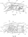
- Fig. 2A
- shows a schematic view of an exemplary embodiment of a joint of a driving mechanism.
- Fig. 2B
- shows another schematic view of the exemplary embodiment of the joint of the driving mechanism.
- Fig. 2C
- shows a schematic top view of the exemplary embodiment of the joint of the driving mechanism.
- Fig. 3A
- shows a schematic perspective rear view of an exemplary embodiment of a lighting mounting in a closed position.
- Fig. 3B
- shows a schematic perspective rear view of the exemplary embodiment of the lighting mounting in an opened position.
- Fig. 4A
- shows a schematic side view of the embodiment of the lighting mounting in the closed position.
- Fig. 4B
- shows a schematic side view of the embodiment of the lighting mounting in the opened position.
- Fig. 5A
- shows a schematic perspective view of an exemplary embodiment of the lighting mounting in the closed position.
- Fig. 5B
- shows a schematic perspective view of the lighting mounting in the opened position.
- The figures are merely schematic representations and serve only to illustrate embodiments of the disclosure. Identical or equivalent elements are in principle provided with the same reference signs.
-
Figures 1A and 1B show an exemplary embodiment of acover unit 100 in a first position (Fig. 1A ) and a second position (Fig. 1B ), respectively. Thecover unit 100 may be used for selectively covering or exposing an opening (not illustrated) in a structure, such as a vehicle body. Thecover unit 100 comprises afirst cover element 102 having a firstaxial end 104 and a secondaxial end 106 when seen in an axial direction X. - The first
axial end 104 is coupled to afirst driving mechanism 108 and the secondaxial end 106 is coupled to asecond driving mechanism 110. Thefirst driving mechanism 108 and thesecond driving mechanism 110 are configured to move thefirst cover element 102 between a first position (Fig. 1A ) and a second position (Fig. 1B ). Further, thefirst driving mechanism 108 can be controlled and/or driven separately and independently from thesecond driving mechanism 110. Thus, the firstaxial end 104 can be moved separately from the secondaxial end 106. - Each of the
first driving mechanism 108 and thesecond driving mechanism 110 comprises anarm 112, which is rotatively connectable to the structure (not illustrated). In theFigs. 1A and 1B , thearm 112 comprises twoconnection points 114, which are configured to be fixed on the structure and each of the connections points 114 comprises aball bearing 116 allowing thearm 112 rotating relative to the structure. Thearm 112 is an assembly of three arms, twosupport arms 118 and a guidingarm 120. - The two
support arms 118 are arranged substantially parallel to each other and each of which comprises oneconnection point 114 at one longitudinal end, and is rotatively connected to the guidingarm 120 at the opposite longitudinal end. Further, thesupport arms 118 may be connected to a drive unit (not illustrated) configured to drive a movement of thearm 112. Thesupport arms 118 can be connected to the same drive, or can be each connected to a separate drive unit. The drive unit may be, for example, an electric motor. - The guiding
arm 120 is connected to thefirst cover element 102 by a joint 122. The joint 122 is able to perform a two-axis rotation and one linear axis movement and will be explained in detail with regard toFigures 2A to 2C , thereby allowing that the firstaxial end 104 and the secondaxial end 106 can be moved different distances. - The joint 122 is shown in more detail in
Figures 2A to 2C . As mentioned above, the joint 122 is configured to allow a two-axis rotation and one linear axis movement. The two-axis rotation is enabled by combining two cylinder joints, wherein a first cylinder joint 124 allows the joint 122 rotating around afirst axis 126, and a second cylinder joint 128 allows the joint 122 rotating around asecond axis 130, being perpendicular to thefirst axis 126. The linear movement is enabled by a linear joint 132 comprising twocylinders 134, first of which being movable along anaxis 136, second of which being moveable along anaxis 138, wherein theaxis 136 and theaxis 138 are arranged substantially parallel to each other. The twocylinders 134 can be moved different distances. Thus, the joint 122 allows compensating for the length differences between the firstaxial end 104 and the secondaxial end 106 of thefirst cover element 102. -
Figures 3A and 3B as well asFigures 4A and 4B partially show an exemplary embodiment of a lighting mounting 140 in a closed position (Figures 3A and4A ) and in an opened position (Figure 3B and4B ), whereinFigures 3A and 3B show a rear perspective view andFigures 4A and 4B show a side view. - The lighting mounting 140 comprises a
lighting unit 142, and thecover unit 100, wherein thecover unit 100 additionally comprises asecond cover element 144 having a firstaxial end 146 and a secondaxial end 148 when seen in the axial direction X. The firstaxial end 146 of thesecond cover element 144 is coupled to athird driving mechanism 150 and the secondaxial end 148 of thesecond cover element 144 is coupled to afourth driving mechanism 152. The assembly and functioning of thesecond cover element 144 substantially corresponds to the assembly and functioning of thefirst cover element 102 and is therefore not explained in detail. - For covering the
lighting unit 142, thecover unit 100 is in a closed position (seeFigures 3A and4A ), wherein thefirst cover element 102 and thesecond cover element 144 contact each other forming a contact line 154 (seeFigure 4A ). In the closed position of thecover unit 100, thelighting unit 142 is in a retracted position (seeFigure 4A ). In an opened position of the cover unit 100 (seeFigures 3B and4B ), thefirst cover element 102 and thesecond cover element 144 are spaced apart from each other (seeFigure 4B ) and thelighting unit 142 is protruding between thefirst cover element 102 and thesecond cover element 144. - As exemplarily shown in
Figures 5A and 5B , the lighting mounting 140 further comprises a mountingbody 156 having anopening 158. The mountingbody 156 is configured to be attached to a body of the vehicle (not illustrated). Theopening 158 is configured to substantially match an opening in the body of the vehicle (not illustrated) and further to expose thelighting unit 142. Thecover unit 100 is configured to selectively cover (seeFigure 5A ) or un-cover or expose, respectively, (seeFigure 5B ) theopening 158. The lighting mounting 140 shown inFigure 5A and 5B is an example for a headlamp mounting. - In
Figures 5A and 5B , it can be seen that theopening 158 has a non-rectangular contour. Exemplarily, the contour of theopening 158 is tapered, which means that a height h1 at a firstaxial end 160 of theopening 158 is smaller than a height h2 at a secondaxial end 162 of theopening 158. Thecover unit 100 is configured such that thefirst cover element 102 and thesecond cover element 144 form a substantiallyhorizontal contact line 154 in the closed position (seeFigure 5A ). - Further, the
first cover element 102 and thesecond cover element 144 are moved by therespective driving mechanism axial end respective cover element axial end respective cover element axial end 104 of thefirst cover element 102 is moved about half of the distance of height h1 in the height direction H by thefirst driving mechanism 108, and the secondaxial end 106 of thefirst cover element 102 is moved about half of the distance of height h2 in the height direction H by thesecond driving mechanism 110 to uncover a first half of the opening 158 (inFigure 5B : an upper half of the opening 158). Further, the firstaxial end 146 of thesecond cover element 144 is moved about half of the distance of height h2 in the height direction H by thethird driving mechanism 150, and the secondaxial end 148 of thesecond cover element 144 is moved about half of the distance of height h2 in the height direction H by thefourth driving mechanism 152 to uncover a second half of the opening 158 (inFigure 5B : a lower half of the opening 158). - However, it is also possible that the
first cover element 102 covers more than half of theopening 158 resulting in thesecond cover element 144 covering the remaining part of theopening 158, or that thefirst cover element 102 covers less than half of theopening 158 resulting in thesecond cover element 144 covering the remaining part of theopening 158. Further, theopening 158 may have other contours and/or shapes, such as a triangular contour, a trapezoidal contour etc. - Other variations to the disclosed embodiments can be understood and effected by those skilled in the art in practicing the claimed invention, from the study of the drawings, the disclosure, and the appended claims. In the claims the word "comprising" does not exclude other elements or steps and the indefinite article "a" or "an" does not exclude a plurality. A single processor or other unit may fulfill the functions of several items or steps recited in the claims. The mere fact that certain measures are recited in mutually different dependent claims does not indicate that a combination of these measures cannot be used to advantage. Any reference signs in the claims should not be construed as limiting the scope of the claims.
-
- 100
- cover unit
- 102
- first cover element
- 104
- first axial end
- 106
- second axial end
- 108
- first driving mechanism
- 110
- second driving mechanism
- 112
- arm
- 114
- connection point
- 116
- ball bearing
- 118
- support arm
- 120
- guiding arm
- 122
- joint
- 124
- first cylinder joint
- 126
- first axis
- 128
- second cylinder joint
- 130
- second axis
- 132
- linear joint
- 134
- cylinder
- 136
- axis
- 138
- axis
- 140
- lighting mounting
- 142
- lighting unit
- 144
- second cover element
- 146
- first axial end
- 148
- second axial end
- 150
- third driving mechanism
- 152
- fourth driving mechanism
- 154
- contact line
- 156
- mounting body
- 158
- opening
- 160
- first axial end
- 162
- second axial end
- X
- axial direction
- H
- height direction
- h1
- first height
- h2
- second height
Claims (14)
- A cover unit (100) for selectively covering an opening in a structure, comprising:at least a first cover element (102) having a first axial end (104) being coupled to a first driving mechanism (108), and a second axial end (106) being coupled to a second driving mechanism (110);the first driving mechanism (108) and the second driving mechanism (110) being configured to move the first cover element (102) between a closed position and an opened position;each of the first driving mechanism (108) and the second driving mechanism (110) being controlled individually, and comprising:an arm (112) being configured to be rotatively coupled to the structure,at least one drive unit being configured to drive a movement of the arm (112), anda joint (122) configured to couple the arm (112) to the respective axial end (104, 106) of the first cover element (102), the joint (122) being configured to allow a two-axis rotation and one linear axis movement,wherein the joint (122) is configured to allow the first axial end (104) and the second axial end (106) of the first cover element (102) to be moved differently during an opening movement and/or a closing movement.
- The cover unit (100) according to claim 1, further comprising:a second cover element (144) having a first axial end (146) being coupled to a third driving mechanism (150), and a second axial end (148) being coupled to a fourth driving mechanism (152);the third driving mechanism (150) and the fourth driving mechanism (152) being configured to move the second cover element (144) between a closed position and an opened position;each of the third driving mechanism (150) and the fourth driving mechanism (152) being controlled individually, and comprising:an arm (112) being configured to be rotatively coupled to the structure,at least one drive unit being configured to drive a movement of the arm (112), anda joint (122) configured to couple the arm (112) to the respective axial end (146, 148) of the second cover element (144), the joint (122) being configured to allow a two-axis rotation and one linear axis movement,wherein the joint (122) is configured to allow the first axial end (146) and the second axial end (148) of the second cover element (144) to be moved differently during an opening movement and/or a closing movement,the first driving mechanism (108), the second driving mechanism (100), the third driving mechanism (150) and the fourth driving mechanism (152) being configured to be attached to the structure,wherein the first cover element (102) and the second cover element (144) are configured to contact each other in the closed position along a contact line (154) to cover the opening, andwherein the first cover element (102) and the second cover element (144) are configured to be spaced apart from each other in the opened position to expose the opening.
- The cover unit (100) according to claim 1 or 2, wherein, during the opening movement, the first axial end (104) of the first cover element (102) is moved a shorter distance than the second axial end (106) of the first cover element (102).
- The cover unit (100) according to any of claims 1 to 3, wherein, during the opening movement, the first axial end (1146) of the second cover element (144) is moved a shorter distance than the second axial end (148) of the second cover element (144).
- The cover unit (100) according to any of claims 1 to 4, wherein each of the first driving mechanism (108) and the second driving mechanism (110) is configured to move the first cover element (102) in at least two different spatial directions.
- The cover unit (100) according to any of claims 2 to 5, wherein each of the third driving mechanism (150) and the fourth driving mechanism (152) is configured to move the second cover element (144) in at least two different spatial directions.
- A use of the cover unit (100) according to any of claims 1 to 6 for covering and/or exposing an opening for a lighting (142) of a vehicle.
- A lighting mounting (140) for a vehicle, comprising:a mounting body (156) comprising an opening (158),a lighting unit (142) comprising at least one light source configured to be exposable in the opening (158) of the mounting body (156), anda cover unit (100) according to any of claims 1 to 6, configured to cover or expose the opening (158).
- The lighting mounting (140) according to claim 8, wherein the opening (158) has a substantially non-rectangular shape.
- The lighting mounting (140) according to claim 8 or 9, wherein the opening (158) is configured to fit to an opening in the body of the vehicle.
- The lighting mounting (140) according to any of claims 8 to 10, wherein the lighting unit (142) further comprises a driving unit configured to move the lighting unit (142) towards the opening (158) and/or to retract the lighting unit (142) from the opening (158).
- The lighting mounting (140) according to any of claims 8 to 11, wherein the driving unit is configured to retract the lighting unit (142) during a closing movement of the cover elements (102, 144) and/or to move the lighting unit (142) towards the opening (158) during an opening movement of the cover elements (102, 144).
- The lighting mounting (140) according any of claims 8 to 12, the lighting unit (142) further comprising several light sources.
- The lighting mounting (140) according to claim 13, wherein the several light sources are configured to spread out fan-like while the lighting unit (142) is moved towards the opening (158).
Priority Applications (3)
| Application Number | Priority Date | Filing Date | Title |
|---|---|---|---|
| EP21202331.1A EP4166392B1 (en) | 2021-10-13 | 2021-10-13 | Cover unit and lighting mounting for vehicle |
| US17/942,427 US11781722B2 (en) | 2021-10-13 | 2022-09-12 | Cover unit and lighting mounting for vehicle |
| CN202211254341.2A CN115959029A (en) | 2021-10-13 | 2022-10-13 | Covering unit and lamp support for vehicle |
Applications Claiming Priority (1)
| Application Number | Priority Date | Filing Date | Title |
|---|---|---|---|
| EP21202331.1A EP4166392B1 (en) | 2021-10-13 | 2021-10-13 | Cover unit and lighting mounting for vehicle |
Publications (2)
| Publication Number | Publication Date |
|---|---|
| EP4166392A1 true EP4166392A1 (en) | 2023-04-19 |
| EP4166392B1 EP4166392B1 (en) | 2023-12-20 |
Family
ID=78179220
Family Applications (1)
| Application Number | Title | Priority Date | Filing Date |
|---|---|---|---|
| EP21202331.1A Active EP4166392B1 (en) | 2021-10-13 | 2021-10-13 | Cover unit and lighting mounting for vehicle |
Country Status (3)
| Country | Link |
|---|---|
| US (1) | US11781722B2 (en) |
| EP (1) | EP4166392B1 (en) |
| CN (1) | CN115959029A (en) |
Citations (6)
| Publication number | Priority date | Publication date | Assignee | Title |
|---|---|---|---|---|
| US3387125A (en) * | 1965-10-13 | 1968-06-04 | Gen Motors Corp | Vehicle headlamp assembly |
| JPS59192632A (en) * | 1983-04-15 | 1984-11-01 | Mazda Motor Corp | Retractable head lamp |
| US4516191A (en) * | 1983-04-15 | 1985-05-07 | Mazda Motor Corporation | Retractable head-light device for automobiles |
| US4602319A (en) * | 1983-04-15 | 1986-07-22 | Mazda Motor Corporation | Retractable head-light device for automobiles |
| JPS61175135A (en) * | 1985-01-30 | 1986-08-06 | Yukio Kawakami | Lighting device for automobile |
| US20020081965A1 (en) * | 2000-11-20 | 2002-06-27 | Trw Automotive Electronics & Components Gmbh & Co. Kg | Air vent for ventilation systems |
Family Cites Families (5)
| Publication number | Priority date | Publication date | Assignee | Title |
|---|---|---|---|---|
| CN201158334Y (en) * | 2007-12-25 | 2008-12-03 | 比亚迪股份有限公司 | Light follow-up steering system |
| US9416933B2 (en) * | 2013-09-27 | 2016-08-16 | Valeo North America, Inc. | Multi-function LED headlamp |
| KR20160020936A (en) * | 2014-08-14 | 2016-02-24 | 강주일 | Light Bars Lift |
| US11346519B2 (en) * | 2018-12-03 | 2022-05-31 | Volvo Car Corporation | Vehicle light assembly including a movable light signature member |
| DE102020104677A1 (en) * | 2020-02-21 | 2021-08-26 | Marelli Automotive Lighting Reutlingen (Germany) GmbH | Automotive headlights |
-
2021
- 2021-10-13 EP EP21202331.1A patent/EP4166392B1/en active Active
-
2022
- 2022-09-12 US US17/942,427 patent/US11781722B2/en active Active
- 2022-10-13 CN CN202211254341.2A patent/CN115959029A/en active Pending
Patent Citations (6)
| Publication number | Priority date | Publication date | Assignee | Title |
|---|---|---|---|---|
| US3387125A (en) * | 1965-10-13 | 1968-06-04 | Gen Motors Corp | Vehicle headlamp assembly |
| JPS59192632A (en) * | 1983-04-15 | 1984-11-01 | Mazda Motor Corp | Retractable head lamp |
| US4516191A (en) * | 1983-04-15 | 1985-05-07 | Mazda Motor Corporation | Retractable head-light device for automobiles |
| US4602319A (en) * | 1983-04-15 | 1986-07-22 | Mazda Motor Corporation | Retractable head-light device for automobiles |
| JPS61175135A (en) * | 1985-01-30 | 1986-08-06 | Yukio Kawakami | Lighting device for automobile |
| US20020081965A1 (en) * | 2000-11-20 | 2002-06-27 | Trw Automotive Electronics & Components Gmbh & Co. Kg | Air vent for ventilation systems |
Also Published As
| Publication number | Publication date |
|---|---|
| EP4166392B1 (en) | 2023-12-20 |
| US20230109766A1 (en) | 2023-04-13 |
| CN115959029A (en) | 2023-04-14 |
| US11781722B2 (en) | 2023-10-10 |
Similar Documents
| Publication | Publication Date | Title |
|---|---|---|
| US7441790B2 (en) | Deployable step and body-side assembly for a vehicle | |
| EP2181890B1 (en) | Vehicle headlight | |
| US20080074895A1 (en) | Convertible vehicle roof having a lamp | |
| JP6998091B1 (en) | Movable headlight cowl | |
| US20140307456A1 (en) | Vehicle lamp | |
| US20210269102A1 (en) | Active aerodynamics liftgate spoiler design with multi 4 bar kinematic linkages | |
| EP4166392B1 (en) | Cover unit and lighting mounting for vehicle | |
| KR20030047656A (en) | Automotive lamp | |
| CN100453894C (en) | Vehicle Lamps | |
| US11846399B2 (en) | Lighting device comprising a movable signaling module and a movable lighting module | |
| JP2018001772A (en) | Power supply structure for sun roof and sun roof unit | |
| US20030145524A1 (en) | Vehicle door open-close device | |
| CN213983229U (en) | Lighting device convenient to adjust illumination angle | |
| CN110816393A (en) | Light joint adjusting mechanism | |
| JP6769911B2 (en) | Vehicle sun visor | |
| US8882168B2 (en) | Tailgate rod | |
| JP7822542B1 (en) | Vehicle door opening and closing device | |
| CN116241825B (en) | Suspended taillight and vehicle | |
| KR100282865B1 (en) | Hood stay of the vehicle | |
| CN102275545B (en) | Installation part structure of rear view mirror | |
| JP2003178608A (en) | Vehicle lighting | |
| JP2004175293A (en) | Sun visor for automobile | |
| JP4628968B2 (en) | Vehicle sun visor | |
| JPH0624272A (en) | Interior lighting device for vehicles | |
| BR0302748B1 (en) | REFLECTOR DEVICE FOR AN ENGINE VEHICLE HEADLIGHT AND ITS ENGINE VEHICLE |
Legal Events
| Date | Code | Title | Description |
|---|---|---|---|
| PUAI | Public reference made under article 153(3) epc to a published international application that has entered the european phase |
Free format text: ORIGINAL CODE: 0009012 |
|
| STAA | Information on the status of an ep patent application or granted ep patent |
Free format text: STATUS: REQUEST FOR EXAMINATION WAS MADE |
|
| 17P | Request for examination filed |
Effective date: 20220629 |
|
| AK | Designated contracting states |
Kind code of ref document: A1 Designated state(s): AL AT BE BG CH CY CZ DE DK EE ES FI FR GB GR HR HU IE IS IT LI LT LU LV MC MK MT NL NO PL PT RO RS SE SI SK SM TR |
|
| RIC1 | Information provided on ipc code assigned before grant |
Ipc: F16C 11/02 20060101ALN20230417BHEP Ipc: B60Q 1/00 20060101ALN20230417BHEP Ipc: F16C 31/02 20060101ALI20230417BHEP Ipc: F16C 11/04 20060101ALI20230417BHEP Ipc: B60Q 1/05 20060101ALI20230417BHEP Ipc: B60Q 1/26 20060101AFI20230417BHEP |
|
| RIC1 | Information provided on ipc code assigned before grant |
Ipc: F16C 11/02 20060101ALN20230511BHEP Ipc: B60Q 1/00 20060101ALN20230511BHEP Ipc: F16C 31/02 20060101ALI20230511BHEP Ipc: F16C 11/04 20060101ALI20230511BHEP Ipc: B60Q 1/05 20060101ALI20230511BHEP Ipc: B60Q 1/26 20060101AFI20230511BHEP |
|
| RIC1 | Information provided on ipc code assigned before grant |
Ipc: F16C 11/02 20060101ALN20230515BHEP Ipc: B60Q 1/00 20060101ALN20230515BHEP Ipc: F16C 31/02 20060101ALI20230515BHEP Ipc: F16C 11/04 20060101ALI20230515BHEP Ipc: B60Q 1/05 20060101ALI20230515BHEP Ipc: B60Q 1/26 20060101AFI20230515BHEP |
|
| RIC1 | Information provided on ipc code assigned before grant |
Ipc: F16C 11/02 20060101ALN20230525BHEP Ipc: B60Q 1/00 20060101ALN20230525BHEP Ipc: F16C 31/02 20060101ALI20230525BHEP Ipc: F16C 11/04 20060101ALI20230525BHEP Ipc: B60Q 1/05 20060101ALI20230525BHEP Ipc: B60Q 1/26 20060101AFI20230525BHEP |
|
| GRAP | Despatch of communication of intention to grant a patent |
Free format text: ORIGINAL CODE: EPIDOSNIGR1 |
|
| STAA | Information on the status of an ep patent application or granted ep patent |
Free format text: STATUS: GRANT OF PATENT IS INTENDED |
|
| RIC1 | Information provided on ipc code assigned before grant |
Ipc: F16C 11/02 20060101ALN20230612BHEP Ipc: B60Q 1/00 20060101ALN20230612BHEP Ipc: F16C 31/02 20060101ALI20230612BHEP Ipc: F16C 11/04 20060101ALI20230612BHEP Ipc: B60Q 1/05 20060101ALI20230612BHEP Ipc: B60Q 1/26 20060101AFI20230612BHEP |
|
| INTG | Intention to grant announced |
Effective date: 20230707 |
|
| GRAS | Grant fee paid |
Free format text: ORIGINAL CODE: EPIDOSNIGR3 |
|
| GRAA | (expected) grant |
Free format text: ORIGINAL CODE: 0009210 |
|
| STAA | Information on the status of an ep patent application or granted ep patent |
Free format text: STATUS: THE PATENT HAS BEEN GRANTED |
|
| AK | Designated contracting states |
Kind code of ref document: B1 Designated state(s): AL AT BE BG CH CY CZ DE DK EE ES FI FR GB GR HR HU IE IS IT LI LT LU LV MC MK MT NL NO PL PT RO RS SE SI SK SM TR |
|
| REG | Reference to a national code |
Ref country code: GB Ref legal event code: FG4D |
|
| REG | Reference to a national code |
Ref country code: DE Ref legal event code: R096 Ref document number: 602021007857 Country of ref document: DE |
|
| REG | Reference to a national code |
Ref country code: CH Ref legal event code: EP |
|
| REG | Reference to a national code |
Ref country code: IE Ref legal event code: FG4D |
|
| P01 | Opt-out of the competence of the unified patent court (upc) registered |
Effective date: 20231219 |
|
| PG25 | Lapsed in a contracting state [announced via postgrant information from national office to epo] |
Ref country code: GR Free format text: LAPSE BECAUSE OF FAILURE TO SUBMIT A TRANSLATION OF THE DESCRIPTION OR TO PAY THE FEE WITHIN THE PRESCRIBED TIME-LIMIT Effective date: 20240321 |
|
| REG | Reference to a national code |
Ref country code: LT Ref legal event code: MG9D |
|
| PG25 | Lapsed in a contracting state [announced via postgrant information from national office to epo] |
Ref country code: LT Free format text: LAPSE BECAUSE OF FAILURE TO SUBMIT A TRANSLATION OF THE DESCRIPTION OR TO PAY THE FEE WITHIN THE PRESCRIBED TIME-LIMIT Effective date: 20231220 |
|
| REG | Reference to a national code |
Ref country code: NL Ref legal event code: MP Effective date: 20231220 |
|
| PG25 | Lapsed in a contracting state [announced via postgrant information from national office to epo] |
Ref country code: ES Free format text: LAPSE BECAUSE OF FAILURE TO SUBMIT A TRANSLATION OF THE DESCRIPTION OR TO PAY THE FEE WITHIN THE PRESCRIBED TIME-LIMIT Effective date: 20231220 |
|
| PG25 | Lapsed in a contracting state [announced via postgrant information from national office to epo] |
Ref country code: LT Free format text: LAPSE BECAUSE OF FAILURE TO SUBMIT A TRANSLATION OF THE DESCRIPTION OR TO PAY THE FEE WITHIN THE PRESCRIBED TIME-LIMIT Effective date: 20231220 Ref country code: GR Free format text: LAPSE BECAUSE OF FAILURE TO SUBMIT A TRANSLATION OF THE DESCRIPTION OR TO PAY THE FEE WITHIN THE PRESCRIBED TIME-LIMIT Effective date: 20240321 Ref country code: FI Free format text: LAPSE BECAUSE OF FAILURE TO SUBMIT A TRANSLATION OF THE DESCRIPTION OR TO PAY THE FEE WITHIN THE PRESCRIBED TIME-LIMIT Effective date: 20231220 Ref country code: ES Free format text: LAPSE BECAUSE OF FAILURE TO SUBMIT A TRANSLATION OF THE DESCRIPTION OR TO PAY THE FEE WITHIN THE PRESCRIBED TIME-LIMIT Effective date: 20231220 Ref country code: BG Free format text: LAPSE BECAUSE OF FAILURE TO SUBMIT A TRANSLATION OF THE DESCRIPTION OR TO PAY THE FEE WITHIN THE PRESCRIBED TIME-LIMIT Effective date: 20240320 |
|
| REG | Reference to a national code |
Ref country code: AT Ref legal event code: MK05 Ref document number: 1642223 Country of ref document: AT Kind code of ref document: T Effective date: 20231220 |
|
| PG25 | Lapsed in a contracting state [announced via postgrant information from national office to epo] |
Ref country code: NL Free format text: LAPSE BECAUSE OF FAILURE TO SUBMIT A TRANSLATION OF THE DESCRIPTION OR TO PAY THE FEE WITHIN THE PRESCRIBED TIME-LIMIT Effective date: 20231220 |
|
| PG25 | Lapsed in a contracting state [announced via postgrant information from national office to epo] |
Ref country code: SE Free format text: LAPSE BECAUSE OF FAILURE TO SUBMIT A TRANSLATION OF THE DESCRIPTION OR TO PAY THE FEE WITHIN THE PRESCRIBED TIME-LIMIT Effective date: 20231220 Ref country code: RS Free format text: LAPSE BECAUSE OF FAILURE TO SUBMIT A TRANSLATION OF THE DESCRIPTION OR TO PAY THE FEE WITHIN THE PRESCRIBED TIME-LIMIT Effective date: 20231220 Ref country code: NO Free format text: LAPSE BECAUSE OF FAILURE TO SUBMIT A TRANSLATION OF THE DESCRIPTION OR TO PAY THE FEE WITHIN THE PRESCRIBED TIME-LIMIT Effective date: 20240320 Ref country code: NL Free format text: LAPSE BECAUSE OF FAILURE TO SUBMIT A TRANSLATION OF THE DESCRIPTION OR TO PAY THE FEE WITHIN THE PRESCRIBED TIME-LIMIT Effective date: 20231220 Ref country code: LV Free format text: LAPSE BECAUSE OF FAILURE TO SUBMIT A TRANSLATION OF THE DESCRIPTION OR TO PAY THE FEE WITHIN THE PRESCRIBED TIME-LIMIT Effective date: 20231220 Ref country code: HR Free format text: LAPSE BECAUSE OF FAILURE TO SUBMIT A TRANSLATION OF THE DESCRIPTION OR TO PAY THE FEE WITHIN THE PRESCRIBED TIME-LIMIT Effective date: 20231220 |
|
| PG25 | Lapsed in a contracting state [announced via postgrant information from national office to epo] |
Ref country code: IS Free format text: LAPSE BECAUSE OF FAILURE TO SUBMIT A TRANSLATION OF THE DESCRIPTION OR TO PAY THE FEE WITHIN THE PRESCRIBED TIME-LIMIT Effective date: 20240420 |
|
| PG25 | Lapsed in a contracting state [announced via postgrant information from national office to epo] |
Ref country code: CZ Free format text: LAPSE BECAUSE OF FAILURE TO SUBMIT A TRANSLATION OF THE DESCRIPTION OR TO PAY THE FEE WITHIN THE PRESCRIBED TIME-LIMIT Effective date: 20231220 Ref country code: AT Free format text: LAPSE BECAUSE OF FAILURE TO SUBMIT A TRANSLATION OF THE DESCRIPTION OR TO PAY THE FEE WITHIN THE PRESCRIBED TIME-LIMIT Effective date: 20231220 |
|
| PG25 | Lapsed in a contracting state [announced via postgrant information from national office to epo] |
Ref country code: SK Free format text: LAPSE BECAUSE OF FAILURE TO SUBMIT A TRANSLATION OF THE DESCRIPTION OR TO PAY THE FEE WITHIN THE PRESCRIBED TIME-LIMIT Effective date: 20231220 |
|
| PG25 | Lapsed in a contracting state [announced via postgrant information from national office to epo] |
Ref country code: SM Free format text: LAPSE BECAUSE OF FAILURE TO SUBMIT A TRANSLATION OF THE DESCRIPTION OR TO PAY THE FEE WITHIN THE PRESCRIBED TIME-LIMIT Effective date: 20231220 Ref country code: SK Free format text: LAPSE BECAUSE OF FAILURE TO SUBMIT A TRANSLATION OF THE DESCRIPTION OR TO PAY THE FEE WITHIN THE PRESCRIBED TIME-LIMIT Effective date: 20231220 Ref country code: RO Free format text: LAPSE BECAUSE OF FAILURE TO SUBMIT A TRANSLATION OF THE DESCRIPTION OR TO PAY THE FEE WITHIN THE PRESCRIBED TIME-LIMIT Effective date: 20231220 Ref country code: IT Free format text: LAPSE BECAUSE OF FAILURE TO SUBMIT A TRANSLATION OF THE DESCRIPTION OR TO PAY THE FEE WITHIN THE PRESCRIBED TIME-LIMIT Effective date: 20231220 Ref country code: IS Free format text: LAPSE BECAUSE OF FAILURE TO SUBMIT A TRANSLATION OF THE DESCRIPTION OR TO PAY THE FEE WITHIN THE PRESCRIBED TIME-LIMIT Effective date: 20240420 Ref country code: EE Free format text: LAPSE BECAUSE OF FAILURE TO SUBMIT A TRANSLATION OF THE DESCRIPTION OR TO PAY THE FEE WITHIN THE PRESCRIBED TIME-LIMIT Effective date: 20231220 Ref country code: CZ Free format text: LAPSE BECAUSE OF FAILURE TO SUBMIT A TRANSLATION OF THE DESCRIPTION OR TO PAY THE FEE WITHIN THE PRESCRIBED TIME-LIMIT Effective date: 20231220 Ref country code: AT Free format text: LAPSE BECAUSE OF FAILURE TO SUBMIT A TRANSLATION OF THE DESCRIPTION OR TO PAY THE FEE WITHIN THE PRESCRIBED TIME-LIMIT Effective date: 20231220 |
|
| PG25 | Lapsed in a contracting state [announced via postgrant information from national office to epo] |
Ref country code: PT Free format text: LAPSE BECAUSE OF FAILURE TO SUBMIT A TRANSLATION OF THE DESCRIPTION OR TO PAY THE FEE WITHIN THE PRESCRIBED TIME-LIMIT Effective date: 20240422 Ref country code: PL Free format text: LAPSE BECAUSE OF FAILURE TO SUBMIT A TRANSLATION OF THE DESCRIPTION OR TO PAY THE FEE WITHIN THE PRESCRIBED TIME-LIMIT Effective date: 20231220 |
|
| PG25 | Lapsed in a contracting state [announced via postgrant information from national office to epo] |
Ref country code: PT Free format text: LAPSE BECAUSE OF FAILURE TO SUBMIT A TRANSLATION OF THE DESCRIPTION OR TO PAY THE FEE WITHIN THE PRESCRIBED TIME-LIMIT Effective date: 20240422 Ref country code: PL Free format text: LAPSE BECAUSE OF FAILURE TO SUBMIT A TRANSLATION OF THE DESCRIPTION OR TO PAY THE FEE WITHIN THE PRESCRIBED TIME-LIMIT Effective date: 20231220 |
|
| REG | Reference to a national code |
Ref country code: DE Ref legal event code: R097 Ref document number: 602021007857 Country of ref document: DE |
|
| PG25 | Lapsed in a contracting state [announced via postgrant information from national office to epo] |
Ref country code: DK Free format text: LAPSE BECAUSE OF FAILURE TO SUBMIT A TRANSLATION OF THE DESCRIPTION OR TO PAY THE FEE WITHIN THE PRESCRIBED TIME-LIMIT Effective date: 20231220 |
|
| PLBE | No opposition filed within time limit |
Free format text: ORIGINAL CODE: 0009261 |
|
| STAA | Information on the status of an ep patent application or granted ep patent |
Free format text: STATUS: NO OPPOSITION FILED WITHIN TIME LIMIT |
|
| PG25 | Lapsed in a contracting state [announced via postgrant information from national office to epo] |
Ref country code: SI Free format text: LAPSE BECAUSE OF FAILURE TO SUBMIT A TRANSLATION OF THE DESCRIPTION OR TO PAY THE FEE WITHIN THE PRESCRIBED TIME-LIMIT Effective date: 20231220 |
|
| PG25 | Lapsed in a contracting state [announced via postgrant information from national office to epo] |
Ref country code: SI Free format text: LAPSE BECAUSE OF FAILURE TO SUBMIT A TRANSLATION OF THE DESCRIPTION OR TO PAY THE FEE WITHIN THE PRESCRIBED TIME-LIMIT Effective date: 20231220 Ref country code: DK Free format text: LAPSE BECAUSE OF FAILURE TO SUBMIT A TRANSLATION OF THE DESCRIPTION OR TO PAY THE FEE WITHIN THE PRESCRIBED TIME-LIMIT Effective date: 20231220 |
|
| 26N | No opposition filed |
Effective date: 20240923 |
|
| REG | Reference to a national code |
Ref country code: CH Ref legal event code: PL |
|
| PG25 | Lapsed in a contracting state [announced via postgrant information from national office to epo] |
Ref country code: MC Free format text: LAPSE BECAUSE OF FAILURE TO SUBMIT A TRANSLATION OF THE DESCRIPTION OR TO PAY THE FEE WITHIN THE PRESCRIBED TIME-LIMIT Effective date: 20231220 |
|
| PG25 | Lapsed in a contracting state [announced via postgrant information from national office to epo] |
Ref country code: BE Free format text: LAPSE BECAUSE OF NON-PAYMENT OF DUE FEES Effective date: 20241031 Ref country code: LU Free format text: LAPSE BECAUSE OF NON-PAYMENT OF DUE FEES Effective date: 20241013 |
|
| PG25 | Lapsed in a contracting state [announced via postgrant information from national office to epo] |
Ref country code: CH Free format text: LAPSE BECAUSE OF NON-PAYMENT OF DUE FEES Effective date: 20241031 |
|
| REG | Reference to a national code |
Ref country code: BE Ref legal event code: MM Effective date: 20241031 |
|
| PGFP | Annual fee paid to national office [announced via postgrant information from national office to epo] |
Ref country code: GB Payment date: 20250923 Year of fee payment: 5 |
|
| PGFP | Annual fee paid to national office [announced via postgrant information from national office to epo] |
Ref country code: FR Payment date: 20250924 Year of fee payment: 5 |
|
| PG25 | Lapsed in a contracting state [announced via postgrant information from national office to epo] |
Ref country code: IE Free format text: LAPSE BECAUSE OF NON-PAYMENT OF DUE FEES Effective date: 20241013 |
|
| PGFP | Annual fee paid to national office [announced via postgrant information from national office to epo] |
Ref country code: DE Payment date: 20250923 Year of fee payment: 5 |
|
| PG25 | Lapsed in a contracting state [announced via postgrant information from national office to epo] |
Ref country code: CY Free format text: LAPSE BECAUSE OF FAILURE TO SUBMIT A TRANSLATION OF THE DESCRIPTION OR TO PAY THE FEE WITHIN THE PRESCRIBED TIME-LIMIT; INVALID AB INITIO Effective date: 20211013 |
|
| PG25 | Lapsed in a contracting state [announced via postgrant information from national office to epo] |
Ref country code: HU Free format text: LAPSE BECAUSE OF FAILURE TO SUBMIT A TRANSLATION OF THE DESCRIPTION OR TO PAY THE FEE WITHIN THE PRESCRIBED TIME-LIMIT; INVALID AB INITIO Effective date: 20211013 |