EP4166355A1 - Fahrzeugluftreifen - Google Patents
Fahrzeugluftreifen Download PDFInfo
- Publication number
- EP4166355A1 EP4166355A1 EP22191597.8A EP22191597A EP4166355A1 EP 4166355 A1 EP4166355 A1 EP 4166355A1 EP 22191597 A EP22191597 A EP 22191597A EP 4166355 A1 EP4166355 A1 EP 4166355A1
- Authority
- EP
- European Patent Office
- Prior art keywords
- groove
- pneumatic vehicle
- microgrooves
- vehicle tire
- tire according
- Prior art date
- Legal status (The legal status is an assumption and is not a legal conclusion. Google has not performed a legal analysis and makes no representation as to the accuracy of the status listed.)
- Granted
Links
Images
Classifications
-
- B—PERFORMING OPERATIONS; TRANSPORTING
- B60—VEHICLES IN GENERAL
- B60C—VEHICLE TYRES; TYRE INFLATION; TYRE CHANGING; CONNECTING VALVES TO INFLATABLE ELASTIC BODIES IN GENERAL; DEVICES OR ARRANGEMENTS RELATED TO TYRES
- B60C11/00—Tyre tread bands; Tread patterns; Anti-skid inserts
- B60C11/03—Tread patterns
- B60C11/0306—Patterns comprising block rows or discontinuous ribs
-
- B—PERFORMING OPERATIONS; TRANSPORTING
- B60—VEHICLES IN GENERAL
- B60C—VEHICLE TYRES; TYRE INFLATION; TYRE CHANGING; CONNECTING VALVES TO INFLATABLE ELASTIC BODIES IN GENERAL; DEVICES OR ARRANGEMENTS RELATED TO TYRES
- B60C11/00—Tyre tread bands; Tread patterns; Anti-skid inserts
- B60C11/03—Tread patterns
- B60C11/12—Tread patterns characterised by the use of narrow slits or incisions, e.g. sipes
- B60C11/1236—Tread patterns characterised by the use of narrow slits or incisions, e.g. sipes with special arrangements in the tread pattern
-
- B—PERFORMING OPERATIONS; TRANSPORTING
- B60—VEHICLES IN GENERAL
- B60C—VEHICLE TYRES; TYRE INFLATION; TYRE CHANGING; CONNECTING VALVES TO INFLATABLE ELASTIC BODIES IN GENERAL; DEVICES OR ARRANGEMENTS RELATED TO TYRES
- B60C11/00—Tyre tread bands; Tread patterns; Anti-skid inserts
- B60C11/03—Tread patterns
- B60C11/13—Tread patterns characterised by the groove cross-section, e.g. for buttressing or preventing stone-trapping
- B60C11/1307—Tread patterns characterised by the groove cross-section, e.g. for buttressing or preventing stone-trapping with special features of the groove walls
- B60C2011/133—Tread patterns characterised by the groove cross-section, e.g. for buttressing or preventing stone-trapping with special features of the groove walls comprising recesses
Definitions
- the invention relates to a pneumatic vehicle tire, in particular for use under wintry driving conditions, with a tread with profile positives, such as tread blocks or profile ribs, and with grooves, such as circumferential grooves, transverse grooves or oblique grooves, which are delimited by a groove base and by groove flanks on the profile positives, wherein Profile positives are present, which are each provided with a number of incisions running parallel to one another, which end on a groove flank, on which diagonally across the groove flank, in particular in a straight line, preferably parallel to one another and at an acute angle of 20° to 40° to the tread periphery Microgrooves are formed, which have a depth of 0.20 mm to 0.50 mm and on the groove flank a width which corresponds at least to their depth and which end at the radially inner end of the respective groove flank.
- profile positives such as tread blocks or profile ribs
- grooves such as circumferential grooves, transverse grooves or oblique grooves,
- Such a vehicle tire is from DE 10 2015 224 293 A1 known.
- the micro-grooves formed on the groove flanks are capable of absorbing snow when driving on snow-covered roads and can therefore transfer the shearing forces occurring when snow slips through the grooves to the groove flanks. These forces deform the profile positive in question in such a way that the incisions formed in the profile and opening out at the groove flanks open somewhat. This also allows snow to accumulate in the cuts and increases snow-to-snow friction and thus traction on snow.
- the object of the invention is to bring about a larger opening of the incisions on the flanks of the grooves in a pneumatic vehicle tire of the type mentioned at the outset and thereby ensure a further improvement in the snow-snow friction.
- microgrooves are connected at an obtuse angle to these, parallel to the groove base or at an acute angle of up to 10° away from the groove base, elongated depressions which, at their deepest point, determined at right angles to the groove flank, have a depth of 0.30 mm to 2.00 mm and whose width at their widest point is 1.00 mm to 3.00 mm and which are at a distance of at least 1.00 mm in front of a adjacent microgroove or a groove delimiting the profile positive.
- microgrooves are followed by elongated depressions just above the groove base and essentially parallel to the groove base, which are wider at their widest point in a plan view of the groove flank than the respective microgroove.
- a particularly significant improvement in snow grip properties can be achieved with elongated depressions, the width of which is 1.50 mm to 2.00 mm at their widest point and the depth of which is 0.50 mm to 1.50 mm at their deepest points.
- the indentations are preferably elongate oval, elongate lens-shaped, slit-shaped or elongate in plan view in such a way that their width increases continuously, beginning with the microgrooves.
- Particularly advantageous for optimal snow-snow friction are indentations that become wider and narrower as they progress, such as the aforementioned indentations that are oval in plan view, or those that become continuously wider over their course up to their ends.
- the indentations can connect to the microgrooves via a "kink” or also via transition curves.
- depressions with extension lengths of 5.00 mm to 20.00 mm, preferably of up to 15.00 mm. It is particularly advantageous if the existing distance from adjacent microgrooves or from transverse grooves opening into the tread block is utilized as optimally as possible.
- the boundary edge of the depressions closer to the tread periphery, viewed in the radial direction, has a distance of 2.00 mm to 4.00 mm from the deepest point of the groove base, in particular up to 3.00mm.
- the indentations therefore retain their advantageous effect on snowy roads via the abrasion of the tread.
- Snow is pressed particularly well into depressions which are rounded in cross section, in particular semi-circular or semicircular-like, or in depressions which are quarter-circle-like or quarter-circular in cross section, with their rounding directly adjoining a transition rounding to the bottom of the groove.
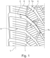
- FIG. 1 shows a top view of a partial development of one half of a tread of a pneumatic vehicle tire for passenger cars, SUVs, vans or light trucks.
- a pneumatic vehicle tire with such a tread is primarily suitable and intended for use under wintry driving conditions, in particular on snow.
- Line L marks the one lateral edge of the part of the tread that touches the ground, which corresponds to the statically determined footprint according to ETRTO standards (load at 70% of the maximum load capacity with an internal pressure of 85% according to the ETRTO standard) in the version applicable at the time of registration.
- the exemplary profiling of the tread shown has oblique grooves 1 which merge into transverse grooves 2 on the tread shoulder side.
- the oblique grooves 1 run at an angle of 45° to 60°, the transverse grooves 2 on the shoulder at an angle of 60° to 90° to the circumferential direction.
- the oblique grooves 1 are the main grooves of the tread and thus belong to those grooves that are designed down to the intended tread depth, which is usually between 6.50 mm and 9.00 mm for tires for passenger cars.
- the transverse grooves 2 and the circumferential grooves 3 can extend at least in sections to the intended profile depth.
- Both the central tread blocks 4 and the shoulder-side tread blocks 5 each have a large number of incisions running parallel to one another 6 provided, in particular traversed.
- the incisions 6 extend essentially in the axial direction or at an angle of up to 30° to the axial direction.
- the incisions 6 are shown as incisions running straight in plan view, but they can also run in a wavy, zigzag or other shape.
- the incisions 6 also have a width that is usual for incisions of the order of 0.40 mm to 0.80 mm, their depth is usually slightly less than the profile depth and can also vary in sections.
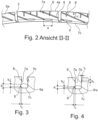
- the oblique grooves 1 are, as shown, for example, in the sectional views in 3 and 4 shows, delimited by opposite flat groove flanks 7a, 7b of the central and shoulder-side profile blocks 4, 5 and a groove base 7c, transitional roundings connect the groove base 7c with the groove flanks 7a, 7b.
- the groove flanks 7a, 7b run in the radial direction, so that, as 3 and 4 show that the oblique grooves 1 have a U-shaped cross section.
- the groove flanks 7a, 7b extend at an acute angle of up to 10° to the radial direction, such that the width of the oblique grooves 1 increases continuously from the groove base 7c to the tread periphery.
- 2 shows a view of three groove flanks 7a that follow one another along an oblique groove 1, the middle groove flank 7a being shown in full and the two laterally adjoining ones being shown in part. 2 also shows the opening points of the two opening-out circumferential grooves 3 as well as the incisions 6 opening out at the groove flanks 7a of the two middle tread blocks 4.
- the opposite groove flanks 7b are preferably designed analogously.
- microgrooves 8 are formed on the block flanks 7a, preferably in an analogous manner also on the groove flanks 7b.
- the microgrooves 8 run obliquely over the groove flanks 7a and preferably in a straight line or slightly arcuate and starting at the tread periphery to the beginning of the transition rounding to the groove base 7c.
- the microgrooves 8 enclose an acute angle ⁇ of 20° to 40° with the block edges 4a of the middle tread blocks 4 present on the tread periphery and the block edges 5a of the shoulder-side tread blocks 5.
- microgrooves 8 preferably run parallel to one another and at mutual normal distances of 3.00 mm to 10.00 mm, preferably up to 7.00 mm, the normal distance between all the microgrooves 8 provided preferably being the same.
- Individual microgrooves 8 are interrupted in their course by circumferential grooves 3 and therefore continue on the groove flank 7a of the adjacent tread block 4, 5.
- Each microgroove 8 also crosses at least one incision 6 at its mouth on a groove flank 7a.
- the microgrooves 8 are preferably rounded, in particular semicircular, rounded indentations on the groove flanks 7a, 7b, have a maximum depth t 1 of 0.20 mm to 0.50 mm determined at right angles to the respective groove flank 7a, 7b and on the groove flanks 7a , 7b has a width b 1 which corresponds at least to its depth t 1 and up to twice the depth t 1 .
- the microgrooves 8 end at the beginning of the transition rounding to the groove base 7c. These ends of some or all of the microgrooves 8 are closed at an obtuse angle and preferably running parallel to the groove base 7c by elongated indentations 9 ( 3 ) or 9' ( 4 ) at.
- the indentations 9, 9′ have, viewed parallel to the groove base 7c, a length e of 5.00 mm to 20.00 mm, in particular up to 15.00 mm, and are preferably designed in such a way that they are spaced apart on the groove flanks 7a, 7b of at least 1.00 mm in front of the next microgroove 8 or one of the circumferential grooves 3.
- the width b 2 of the depressions 9, 9' increases continuously, starting at their connection points to the microgrooves 8 up to their free ends.
- the indentations 9, 9' run at an acute angle of up to 10° to the groove base 7c and in the direction of the tread periphery.
- the recess 9 is rounded in cross-section, in particular semi-circular or at most semi-circular, and has a depth t 2 of 0.30 mm to 2 00 mm, in particular 0.50 mm to 1.50 mm, their width b 2 at its widest point is 1.00 mm to 3.00 mm, in particular up to 1.50 mm to 2.00 mm.
- the boundary edge 9a of the recess 9 closer to the periphery of the tread is located, determined in the radial direction, from the deepest point of the groove base 7c at a distance a of 2.00 mm to 4.00 mm, in particular up to 3.00 mm.
- the depression 9' has a cross section in the shape of a quarter circle or similar to a quarter circle, with the quarter circle or the rounding directly adjoining the transition rounding to the groove base 7c.
- the greatest width b 2 , the greatest depth t 2 of the depression 9' and the distance a from the boundary edge 9'a are in the range of the dimensions mentioned for the width b 2 , the depth t 2 and the distance a.
- the indentations have a V-shaped cross section or any other desired cross section with the widths and depths mentioned.
Landscapes
- Engineering & Computer Science (AREA)
- Mechanical Engineering (AREA)
- Tires In General (AREA)
Abstract
Description
- Die Erfindung betrifft einen Fahrzeugluftreifen, insbesondere für den Einsatz unter winterlichen Fahrbedingungen, mit einem Laufstreifen mit Profilpositiven, wie Profilblöcke oder Profilrippen, und mit Rillen, wie Umfangsrillen, Querrillen oder Schrägrillen, welche von einem Rillengrund und von Rillenflanken an den Profilpositiven begrenzt sind, wobei Profilpositive vorhanden sind, welche jeweils mit einer Anzahl von parallel zueinander verlaufenden Einschnitten versehen sind, die an einer Rillenflanke enden, auf welcher schräg über die Rillenflanke, insbesondere geradlinig, bevorzugt parallel zueinander und unter einem spitzen Winkel von 20° bis 40° zur Laufstreifenperipherie verlaufende Mikrorillen ausgebildet sind, welche eine Tiefe von 0,20 mm bis 0,50 mm und an der Rillenflanke eine Breite aufweisen, die zumindest ihrer Tiefe entspricht und welche beim radial inneren Ende der jeweiligen Rillenflanke enden.
- Ein derartiger Fahrzeugluftreifen ist aus der
DE 10 2015 224 293 A1 bekannt. Die an den Rillenflanken ausgebildeten Mikrorillen sind in der Lage, beim Fahren auf mit Schnee bedeckten Fahrbahnen Schnee aufzunehmen und können daher die beim Durchrutschen von Schnee durch die Rillen hindurch entstehenden Scherkräfte auf die Rillenflanken übertragen. Diese Kräfte verformen das betreffende Profilpositiv derart, dass sich die im Profil ausgebildeten und an den Rillenflanken mündenden Einschnitte etwas öffnen. Dadurch kann sich auch Schnee in den Einschnitten ansammeln und die Schnee-Schnee-Reibung und damit die Traktion auf Schnee werden erhöht. - Der Erfindung liegt die Aufgabe zugrunde, bei einem Fahrzeugluftreifen der eingangs genannten Art eine größere Öffnung der Einschnitte an den Rillenflanken zu bewirken und dadurch für eine weitere Verbesserung der Schnee-Schnee-Reibung zu sorgen.
- Gelöst wird die gestellte Aufgabe erfindungsgemäß dadurch, dass an radial innere Enden von Mikrorillen unter einem stumpfen Winkel zu diesen, parallel zum Rillengrund oder unter einem spitzen Winkel von bis zu 10° weg vom Rillengrund verlaufende, langgestreckte Vertiefungen anschließen, die an ihrer tiefsten Stelle, im rechten Winkel zur Rillenflanke ermittelt, eine Tiefe von 0,30 mm bis 2,00 mm aufweisen und deren Breite an ihrer breitesten Stelle 1,00 mm bis 3,00 mm beträgt und welche in einem Abstand von mindestens 1,00 mm vor einer benachbarten Mikrorille oder einer das Profilpositiv begrenzenden Rille enden.
- Gemäß der Erfindung schließen an Mikrorillen knapp oberhalb des Rillengrundes und im Wesentlichen parallel zum Rillengrund verlaufend, langgestreckte Vertiefungen an, die in Draufsicht auf die Rillenflanke an ihrer breitesten Stelle breiter sind als die jeweilige Mikrorille. Diese Maßnahmen ermöglichen es, dass beim Fahren auf Schnee mehr Schnee in die Mikrorillen hineingepresst wird, die Schnee-/Rillenflankenreibung nochmals erhöht wird, die Einschnitte besser geöffnet werden und mehr Schnee zur Erhöhung der Schnee-Schnee-Reibung aufnehmen können.
- Eine besonders deutliche Verbesserung der Schneegriffeigenschaften lassen sich mit langgestreckten Vertiefungen erzielen, deren Breite an ihrer breitesten Stelle 1,50 mm bis 2,00 mm und deren Tiefe an ihren tiefsten Stellen 0,50 mm bis 1,50 mm beträgt.
- Die Vertiefungen sind bevorzugt in Draufsicht langgestreckt oval, langgestreckt linsenförmig, schlitzförmig oder derart langgestreckt gestaltet, dass ihre Breite, beginnend bei den Mikrorillen kontinuierlich zunimmt. Besonders vorteilhaft für eine optimale Schnee-Schnee-Reibung sind dabei Vertiefungen, die in ihrem Verlauf breiter und wieder schmäler werden, wie die erwähnten in Draufsicht ovalen Vertiefungen, oder solche, die über ihren Verlauf bis zu ihren Enden kontinuierlich breiter werden.
- Die Vertiefungen können an den Mikrorillen über einen "Knick" oder auch über Übergangsrundungen anschließen.
- Besonders vorteilhaft sind ferner Ausgestaltungen der Vertiefungen mit Erstreckungslängen von 5,00 mm bis 20,00 mm, vorzugsweise von bis zu 15,00 mm. Besonders vorteilhaft ist es, wenn der vorhandene Abstand zu benachbarten Mikrorillen oder zu in den Profilblock einmündenden Querrillen möglichst optimal ausgenützt wird.
- Bezüglich der Position der Vertiefungen an den Rillenflanken ist es besonders günstig, wenn die zur Laufstreifenperipherienähe näher befindliche Begrenzungskante der Vertiefungen, in radialer Richtung betrachtet, von der tiefsten Stelle des Rillengrundes einen Abstand von 2,00 mm bis 4,00 mm, insbesondere bis zu 3,00 mm, aufweist. Die Vertiefungen behalten daher über den Laufstreifenabrieb ihre vorteilhafte Wirkung auf schneeiger Fahrbahn.
- Besonders gut wird Schnee in Vertiefungen eingepresst, welche im Querschnitt gerundet, insbesondere halbkreisförmig oder halbkreisähnlich, gerundet sind oder in Vertiefungen, welche im Querschnitt viertelkreisähnlich oder viertelkreisförmig sind, wobei ihre Rundung unmittelbar an eine Übergangsrundung zum Rillengrund anschließt.
- Weitere Merkmale, Vorteile und Einzelheiten der Erfindung werden nun anhand der schematischen Zeichnung, die Ausführungsbeispiele darstellt, näher beschrieben. Dabei zeigen
-
Fig. 1 eine Draufsicht auf die eine Hälfte eines Laufstreifens eines Fahrzeugluftreifens, -
Fig. 2 eine Ansicht auf Rillenflanken von Profilblöcken, die eine Rille begrenzen, gemäß der Linie II-II derFig. 1 , -
Fig. 3 einen Schnitt entlang der Linie III-III derFig. 1 in vergrößerter Darstellung und -
Fig. 4 . in einem zuFig. 3 analogen Schnitt eine weitere Ausführungsform der Erfindung. -
Fig. 1 zeigt eine Draufsicht auf eine Teilabwicklung der einen Hälfte eines Laufstreifens eines Fahrzeugluftreifens für Personenkraftwagen, SUVs, Vans oder Light Trucks. Ein Fahrzeugluftreifen mit einem derartigen Laufstreifen ist vor allem für den Einsatz unter winterlichen Fahrbedingungen, insbesondere auf Schnee, geeignet und vorgesehen. Die Linie L kennzeichnet den einen seitlichen Rand des bodenberührenden Teils des Laufstreifens, welcher dem statisch ermittelten Footprint gemäß E.T.R.T.O.-Standards (Last bei 70 % der maximalen Tragfähigkeit bei einem Innendruck von 85 % nach E.T.R.T.O.-Norm) in der zum Anmeldezeitpunkt geltenden Fassung entspricht. - Die in
Fig. 1 gezeigte beispielhafte Profilierung des Laufstreifens weist Schrägrillen 1 auf, die laufstreifenschulterseitig in Querrillen 2 übergehen. Die Schrägrillen 1 verlaufen unter einem Winkel von 45° bis 60°, die schulterseitigen Querrillen 2 unter einem Winkel von 60° bis 90° zur Umfangsrichtung. Paare von Umfangsrillen 3, die zur Umfangsrichtung unter einem Winkel von bis zu 20° verlaufen und in Umfangsrichtung aufeinanderfolgende Schrägrillen 1 miteinander verbinden, bewirken eine Gliederung des Laufstreifens in mittlere Profilblöcke 4 und in schulterseitige Profilblöcke 5. Beim gezeigten Ausführungsbeispiel sind die Schrägrillen 1 die Hauptrillen des Laufstreifens und gehören somit zu jenen Rillen, die bis auf die vorgesehene Profiltiefe ausgeführt sind, die bei Reifen für Personenkraftwagen üblicherweise zwischen 6,50 mm und 9,00 mm beträgt. Darüber hinaus können auch die Querrillen 2 und die Umfangsrillen 3 zumindest abschnittsweise bis in die vorgesehen Profiltiefe reichen. - Sowohl die mittleren Profilblöcke 4 als auch die schulterseitigen Profilblöcke 5 sind jeweils mit einer Vielzahl von jeweils parallel zueinander verlaufenden Einschnitten 6 versehen, insbesondere durchquert. Bei der gezeigten Ausführung und wie es bei Laufstreifen für Winterreifen üblich ist, erstrecken sich die Einschnitte 6 im Wesentlichen in axialer Richtung bzw. unter einem Winkel von bis zu 30° zur axialen Richtung. Die Einschnitte 6 sind als in Draufsicht gerade verlaufende Einschnitte dargestellt, können jedoch auch in Wellen-, Zickzack- oder sonstiger Form verlaufen. Die Einschnitte 6 weisen ferner eine für Einschnitte übliche Breite in der Größenordnung von 0,40 mm bis 0,80 mm auf, ihre Tiefe ist üblicherweise etwas geringer als die Profiltiefe und kann auch abschnittsweise variieren.
- Die Schrägrillen 1 sind, wie es beispielsweise die Schnittdarstellungen in
Fig. 3 und Fig. 4 zeigt, von gegenüberliegenden ebenen Rillenflanken 7a, 7b der mittleren und der schulterseitigen Profilblöcke 4, 5 und einem Rillengrund 7c begrenzt, Übergangsrundungen verbinden den Rillengrund 7c mit den Rillenflanken 7a, 7b. - Die Rillenflanken 7a, 7b verlaufen bei den gezeigten Ausführungsbeispielen in radialer Richtung, sodass, wie es
Fig. 3 und Fig. 4 zeigen, die Schrägrillen 1 einen U-förmigen Querschnitt aufweisen. Alternativ verlaufen die Rillenflanken 7a, 7b einem spitzen Winkel von bis zu 10° zur radialen Richtung, derart, dass die Breite der Schrägrillen 1 vom Rillengrund 7c bis zur Laufstreifenperipherie kontinuierlich zunimmt. -
Fig. 2 zeigt eine Sicht auf drei entlang einer Schrägrille 1 aufeinanderfolgenden Rillenflanken 7a, wobei die mittlere Rillenflanke 7a komplett und die beiden seitlich anschließenden jeweils zum Teil dargestellt sind.Fig. 2 zeigt ferner die Einmündungsstellen der beiden einmündenden Umfangsrillen 3 sowie der an den Rillenflanken 7a der beiden mittleren Profilblöcke 4 einmündenden Einschnitte 6. Die gegenüberliegenden Rillenflanken 7b sind bevorzugt analog gestaltet. - Wie insbesondere
Fig. 2 zeigt sind an den Blockflankten 7a, bevorzugt in analoger Weise auch an den Rillenflanken 7b, Mikrorillen 8 ausgebildet. Die Mikrorillen 8 verlaufen schräg über die Rillenflanken 7a sowie bevorzugt geradlinig oder leicht bogenförmig und beginnend bei der Laufstreifenperipherie bis zum Beginn der Übergangsrundungen zum Rillengrund 7c. Mit den an der Laufstreifenperipherie vorliegenden Blockkanten 4a der mittleren Profilblöcke 4 und den Blockkanten 5a der schulterseitigen Profilblöcke 5 schließen die Mikrorillen 8 einem spitzen Winkel α von 20° bis 40° ein. Bevorzugt verlaufen die Mikrorillen 8 parallel zueinander und unter gegenseitigen Normalabständen von 3,00 mm bis 10,00 mm, vorzugsweise bis zu 7,00 mm, wobei der Normalabstand sämtlicher vorgesehener Mikrorillen 8 bevorzugt gleich groß ist. Einzelne Mikrorillen 8 sind ihrem Verlauf durch Umfangsrillen 3 unterbrochen, setzen sich daher an der Rillenflanke 7a des benachbarten Profilblockes 4, 5 fort. Jede Mikrorille 8 kreuzt ferner zumindest einen Einschnitt 6 an seiner Mündungsstelle an einer Rillenflanke 7a. - Die Mikrorillen 8 sind bevorzugt gerundete, insbesondere halbkreisförmig gerundete Vertiefungen an den Rillenflanken 7a, 7b, weisen eine im rechten Winkel gegenüber der jeweiligen Rillenflanke 7a, 7b ermittelte größte Tiefe t1 von 0,20 mm bis 0,50 mm und an den Rillenflanken 7a, 7b eine Breite b1 auf, die zumindest ihrer Tiefe t1 und bis zum Zweifachen der Tiefe t1, entspricht.
- Wie bereits erwähnt enden die Mikrorillen 8 beim Beginn der Übergangsrundungen zum Rillengrund 7c. An diese Enden einiger oder sämtlicher Mikrorillen 8 schließen unter einem stumpfen Winkel und vorzugsweise parallel zum Rillengrund 7c verlaufend langgestreckte, in Draufsicht insbesondere langgestreckt oval, langgestreckt linsenförmig oder schlitzförmig ausgebildete Vertiefungen 9 (
Fig. 3 ) bzw. 9' (Fig. 4 ) an. Die Vertiefungen 9, 9' besitzen, parallel zum Rillengrund 7c betrachtet, eine Erstreckungslänge e von 5,00 mm bis 20,00 mm, insbesondere bis 15.00 mm, und sind bevorzugt derart ausgeführt, dass sie auf den Rillenflanken 7a, 7b in einem Abstand von mindestens 1,00 mm vor der nächsten Mikrorillen 8 oder einer der Umfangsrillen 3 enden. Bei einer alternativen Ausführung nimmt die Breite b2 der Vertiefungen 9, 9' beginnend bei ihren Anschlussstellen an die Mikrorillen 8 bis zu ihren freien Enden kontinuierlich zu. Bei einer weiteren alternativen Ausführung verlaufen die Vertiefungen 9, 9' unter einem spitzen Winkel von bis zu 10° zum Rillengrund 7c und in Richtung Laufstreifenperipherie. -
Fig. 3 zeigt eine bevorzugte Ausführung der Vertiefung 9. Die Vertiefung 9 ist im Querschnitt gerundet, insbesondere halbkreisförmig oder höchstens halbkreisförmig, und weist an ihrer tiefsten Stelle, im rechten Winkel zur Rillenflanke 7a, 7b ermittelt, eine Tiefe t2 von 0,30 mm bis 2,00 mm auf, insbesondere 0,50 mm bis 1,50 mm, ihre Breite b2 an ihrer breitesten Stelle beträgt 1,00 mm bis 3,00 mm, insbesondere bis 1,50 mm bis 2,00 mm. Die zur Laufstreifenperipherie näher befindliche Begrenzungskante 9a der Vertiefung 9 befindet sich, in radialer Richtung ermittelt, gegenüber der tiefsten Stelle des Rillengrundes 7c in einem Abstand a von 2,00 mm bis 4,00 mm, insbesondere bis 3,00 mm. -
Fig. 4 zeigt eine bevorzugte Ausführung der Vertiefung 9'. Bei diesem Ausführungsbeispiel weist die Vertiefung 9' einen viertelkreisförmigen oder viertelkreisähnlichen Querschnitt auf, wobei der Viertelkreis bzw. die Rundung unmittelbar an die Übergangsrundung zum Rillengrund 7c anschließt. Die größte Breite b2, die größte Tiefe t2 der Vertiefung 9' sowie der Abstand a zur Begrenzungskante 9'a bewegen sich im Bereich der erwähnten Dimensionen für die Breite b2, die Tiefe t2 und den Abstand a. - Bei weiteren, nicht gezeigten Ausführungsvarianten sind die Vertiefungen im Querschnitt V-förmig gestaltet oder weisen einen sonstigen beliebigen Querschnitt mit den erwähnten Breiten und Tiefen auf.
-
- 1
- Schrägrille
- 2
- Querrille
- 3
- Umfangsrille
- 4
- mittlerer Profilblock
- 5
- schulterseitiger Profilblock
- 4a, 5a
- Blockkante
- 6
- Einschnitt
- 7a, 7b
- Rillenflanke
- 7c
- Rillengrund
- 8
- Mikrorille
- 9, 9'
- Vertiefung
- 9a, 9'a
- Begrenzungskante
- b1, b2
- Breite
- t1, t2
- Tiefe
- e
- Erstreckungslänge
Claims (11)
- Fahrzeugluftreifen, insbesondere für den Einsatz unter winterlichen Fahrbedingungen, mit einem Laufstreifen mit Profilpositiven, wie Profilblöcke (4, 5) oder Profilrippen, und mit Rillen (1, 3), wie Umfangsrillen, Querrillen oder Schrägrillen, welche von einem Rillengrund (7c) und von Rillenflanken (7a, 7b) an den Profilpositiven begrenzt sind, wobei Profilpositive vorhanden sind, welche jeweils mit einer Anzahl von parallel zueinander verlaufenden Einschnitten (6) versehen sind, die an einer Rillenflanke (7a, 7b) enden, auf welcher schräg über die Rillenflanke (7a, 7b), insbesondere geradlinig, bevorzugt parallel zueinander und unter einem spitzen Winkel (a) von 20° bis 40° zur Laufstreifenperipherie verlaufende Mikrorillen (8) ausgebildet sind, welche eine Tiefe (t1) von 0,20 mm bis 0,50 mm und an der Rillenflanke eine Breite(b1) aufweisen, die zumindest ihrer Tiefe entspricht und welche beim radial inneren Ende der jeweiligen Rillenflanke (7a, 7b) enden,
dadurch gekennzeichnet,
dass an radial innere Enden von Mikrorillen (8) unter einem stumpfen Winkel zu diesen, parallel zum Rillengrund (7c) oder unter einem spitzen Winkel von bis zu 10° weg vom Rillengrund (7c) verlaufende, langgestreckte Vertiefungen (9, 9') anschließen, die an ihrer tiefsten Stelle, im rechten Winkel zur Rillenflanke (7a, 7b) ermittelt, eine Tiefe (t2) von 0,30 mm bis 2,00 mm aufweisen und deren Breite (b2) an ihrer breitesten Stelle 1,00 mm bis 3,00 mm, beträgt und welche in einem Abstand von mindestens 1,00 mm vor einer benachbarten Mikrorille (8) oder einer das Profilpositiv begrenzenden Rille (3) enden. - Fahrzeugluftreifen nach Anspruch 1, dadurch gekennzeichnet, dass die Breite (b2) der Vertiefungen (9, 9') an ihrer breitesten Stelle 1,50 mm bis 2,00 mm, beträgt.
- Fahrzeugluftreifen nach Anspruch 1, dadurch gekennzeichnet, dass die Tiefe (t2) der Vertiefungen (9, 9') an ihrer tiefsten Stelle 0,50 mm bis 1,50 mm beträgt.
- Fahrzeugluftreifen nach einem der Ansprüche 1 bis 3, dadurch gekennzeichnet, dass die Vertiefungen (9, 9') in Draufsicht langgestreckt oval, langgestreckt linsenförmig oder schlitzförmig ausgebildet sind.
- Fahrzeugluftreifen nach einem der Ansprüche 1 bis 3, dadurch gekennzeichnet, dass die Vertiefungen (9, 9') in Draufsicht derart langestreckt sind, dass ihre Breite, beginnend bei den Mikrorillen (8), kontinuierlich zunimmt.
- Fahrzeugluftreifen nach einem der Ansprüche 1 bis 5, dadurch gekennzeichnet, dass die Breite der Vertiefungen (9, 9') bei ihrem Beginn bei den Mikrorillen (8) der Breite der Mikrorillen (8) an dieser Stelle entspricht.
- Fahrzeugluftreifen nach einem der Ansprüche 1 bis 6, dadurch gekennzeichnet, dass die Vertiefungen (9, 9') über Übergangsrundungen an die Mikrorillen (8) anschließen.
- Fahrzeugluftreifen nach einem der Ansprüche 1 bis 7, dadurch gekennzeichnet, dass die Vertiefungen (9, 9') eine Erstreckungslänge (e) von 5,00 mm bis 20,00 mm, vorzugsweise von bis zu 15,00 mm, aufweisen.
- Fahrzeugluftreifen nach einem der Ansprüche 1 bis 8, dadurch gekennzeichnet, dass die Vertiefungen (9, 9') eine zur Laufstreifenperipherie näher befindliche Begrenzungskante (9a, 9'a) aufweisen, welche, in radialer Richtung betrachtet, zur tiefsten Stelle des Rillengrundes (7c) einen Abstand (a) von 2,00 mm bis 4,00 mm, insbesondere bis 3,00 mm, aufweist.
- Fahrzeugluftreifen nach einem der Ansprüche 1 bis 9, dadurch gekennzeichnet, dass die Vertiefungen (9) im Querschnitt gerundet, insbesondere halbkreisförmig oder halbkreisähnlich, gerundet sind.
- Fahrzeugluftreifen nach einem der Ansprüche 1 bis 10, dadurch gekennzeichnet, dass die Vertiefungen (9') im Querschnitt viertelkreisähnlich oder viertelkreisförmig sind, wobei ihre Rundung unmittelbar an eine Übergangsrundung zum Rillengrund (7c) anschließt.
Applications Claiming Priority (1)
| Application Number | Priority Date | Filing Date | Title |
|---|---|---|---|
| DE102021211651.5A DE102021211651A1 (de) | 2021-10-15 | 2021-10-15 | Fahrzeugluftreifen |
Publications (2)
| Publication Number | Publication Date |
|---|---|
| EP4166355A1 true EP4166355A1 (de) | 2023-04-19 |
| EP4166355B1 EP4166355B1 (de) | 2024-06-26 |
Family
ID=83050036
Family Applications (1)
| Application Number | Title | Priority Date | Filing Date |
|---|---|---|---|
| EP22191597.8A Active EP4166355B1 (de) | 2021-10-15 | 2022-08-23 | Fahrzeugluftreifen |
Country Status (2)
| Country | Link |
|---|---|
| EP (1) | EP4166355B1 (de) |
| DE (1) | DE102021211651A1 (de) |
Citations (4)
| Publication number | Priority date | Publication date | Assignee | Title |
|---|---|---|---|---|
| US20090294003A1 (en) * | 2008-06-02 | 2009-12-03 | The Yokohama Rubber Co., Ltd. | Pneumatic tire |
| DE102010006051A1 (de) * | 2009-02-16 | 2010-08-19 | The Yokohama Rubber Co., Ltd. | Pneumatischer Reifen |
| US20140360641A1 (en) * | 2013-06-05 | 2014-12-11 | Cooper Tire & Rubber Company | Tire tread with angled rib groove walls |
| DE102015224293A1 (de) | 2015-12-04 | 2017-06-08 | Continental Reifen Deutschland Gmbh | Fahrzeugluftreifen |
-
2021
- 2021-10-15 DE DE102021211651.5A patent/DE102021211651A1/de active Pending
-
2022
- 2022-08-23 EP EP22191597.8A patent/EP4166355B1/de active Active
Patent Citations (4)
| Publication number | Priority date | Publication date | Assignee | Title |
|---|---|---|---|---|
| US20090294003A1 (en) * | 2008-06-02 | 2009-12-03 | The Yokohama Rubber Co., Ltd. | Pneumatic tire |
| DE102010006051A1 (de) * | 2009-02-16 | 2010-08-19 | The Yokohama Rubber Co., Ltd. | Pneumatischer Reifen |
| US20140360641A1 (en) * | 2013-06-05 | 2014-12-11 | Cooper Tire & Rubber Company | Tire tread with angled rib groove walls |
| DE102015224293A1 (de) | 2015-12-04 | 2017-06-08 | Continental Reifen Deutschland Gmbh | Fahrzeugluftreifen |
Also Published As
| Publication number | Publication date |
|---|---|
| DE102021211651A1 (de) | 2023-04-20 |
| EP4166355B1 (de) | 2024-06-26 |
Similar Documents
| Publication | Publication Date | Title |
|---|---|---|
| EP3589500B1 (de) | Fahrzeugluftreifen | |
| EP3888948A1 (de) | Fahrzeugluftreifen, insbesondere nutzfahrzeugreifen | |
| DE102019213044A1 (de) | Fahrzeugluftreifen | |
| DE102015224291A1 (de) | Fahrzeugluftreifen | |
| EP3383671B1 (de) | Fahrzeugluftreifen | |
| EP3724006A1 (de) | Nutzfahrzeugreifen | |
| EP4347277A1 (de) | Fahrzeugluftreifen | |
| EP3441241B1 (de) | Fahrzeugluftreifen | |
| EP4058304B1 (de) | Fahrzeugluftreifen | |
| EP2138329B1 (de) | Laufflächenprofil für einen Fahrzeugluftreifen | |
| EP3079925B1 (de) | Fahrzeugluftreifen | |
| EP4244079B1 (de) | Fahrzeugluftreifen | |
| EP4166355B1 (de) | Fahrzeugluftreifen | |
| EP3300925B1 (de) | Fahrzeugluftreifen | |
| EP2138328B1 (de) | Fahrzeugluftreifen | |
| EP4347276B1 (de) | Fahrzeugluftreifen | |
| EP4173847A1 (de) | Fahrzeugluftreifen | |
| EP2090443B1 (de) | Fahrzeugluftreifen | |
| EP4140774B1 (de) | Fahrzeugreifen | |
| EP3831619A1 (de) | Fahrzeugluftreifen | |
| EP4434768B1 (de) | Fahrzeugluftreifen | |
| DE102020204070A1 (de) | Fahrzeugluftreifen | |
| EP3277524B1 (de) | Fahrzeugluftreifen | |
| EP4140776B1 (de) | Fahrzeugluftreifen | |
| DE102021201350A1 (de) | Fahrzeugluftreifen |
Legal Events
| Date | Code | Title | Description |
|---|---|---|---|
| PUAI | Public reference made under article 153(3) epc to a published international application that has entered the european phase |
Free format text: ORIGINAL CODE: 0009012 |
|
| STAA | Information on the status of an ep patent application or granted ep patent |
Free format text: STATUS: THE APPLICATION HAS BEEN PUBLISHED |
|
| AK | Designated contracting states |
Kind code of ref document: A1 Designated state(s): AL AT BE BG CH CY CZ DE DK EE ES FI FR GB GR HR HU IE IS IT LI LT LU LV MC MK MT NL NO PL PT RO RS SE SI SK SM TR |
|
| STAA | Information on the status of an ep patent application or granted ep patent |
Free format text: STATUS: REQUEST FOR EXAMINATION WAS MADE |
|
| 17P | Request for examination filed |
Effective date: 20231019 |
|
| RBV | Designated contracting states (corrected) |
Designated state(s): AL AT BE BG CH CY CZ DE DK EE ES FI FR GB GR HR HU IE IS IT LI LT LU LV MC MK MT NL NO PL PT RO RS SE SI SK SM TR |
|
| RAP3 | Party data changed (applicant data changed or rights of an application transferred) |
Owner name: CONTINENTAL REIFEN DEUTSCHLAND GMBH |
|
| GRAP | Despatch of communication of intention to grant a patent |
Free format text: ORIGINAL CODE: EPIDOSNIGR1 |
|
| STAA | Information on the status of an ep patent application or granted ep patent |
Free format text: STATUS: GRANT OF PATENT IS INTENDED |
|
| RIC1 | Information provided on ipc code assigned before grant |
Ipc: B60C 11/13 20060101ALI20240305BHEP Ipc: B60C 11/12 20060101ALI20240305BHEP Ipc: B60C 11/03 20060101AFI20240305BHEP |
|
| INTG | Intention to grant announced |
Effective date: 20240319 |
|
| GRAS | Grant fee paid |
Free format text: ORIGINAL CODE: EPIDOSNIGR3 |
|
| GRAA | (expected) grant |
Free format text: ORIGINAL CODE: 0009210 |
|
| STAA | Information on the status of an ep patent application or granted ep patent |
Free format text: STATUS: THE PATENT HAS BEEN GRANTED |
|
| P01 | Opt-out of the competence of the unified patent court (upc) registered |
Effective date: 20240515 |
|
| AK | Designated contracting states |
Kind code of ref document: B1 Designated state(s): AL AT BE BG CH CY CZ DE DK EE ES FI FR GB GR HR HU IE IS IT LI LT LU LV MC MK MT NL NO PL PT RO RS SE SI SK SM TR |
|
| REG | Reference to a national code |
Ref country code: GB Ref legal event code: FG4D Free format text: NOT ENGLISH |
|
| REG | Reference to a national code |
Ref country code: CH Ref legal event code: EP |
|
| REG | Reference to a national code |
Ref country code: DE Ref legal event code: R096 Ref document number: 502022001118 Country of ref document: DE |
|
| PG25 | Lapsed in a contracting state [announced via postgrant information from national office to epo] |
Ref country code: BG Free format text: LAPSE BECAUSE OF FAILURE TO SUBMIT A TRANSLATION OF THE DESCRIPTION OR TO PAY THE FEE WITHIN THE PRESCRIBED TIME-LIMIT Effective date: 20240626 |
|
| PG25 | Lapsed in a contracting state [announced via postgrant information from national office to epo] |
Ref country code: FI Free format text: LAPSE BECAUSE OF FAILURE TO SUBMIT A TRANSLATION OF THE DESCRIPTION OR TO PAY THE FEE WITHIN THE PRESCRIBED TIME-LIMIT Effective date: 20240626 Ref country code: HR Free format text: LAPSE BECAUSE OF FAILURE TO SUBMIT A TRANSLATION OF THE DESCRIPTION OR TO PAY THE FEE WITHIN THE PRESCRIBED TIME-LIMIT Effective date: 20240626 |
|
| REG | Reference to a national code |
Ref country code: LT Ref legal event code: MG9D |
|
| PG25 | Lapsed in a contracting state [announced via postgrant information from national office to epo] |
Ref country code: GR Free format text: LAPSE BECAUSE OF FAILURE TO SUBMIT A TRANSLATION OF THE DESCRIPTION OR TO PAY THE FEE WITHIN THE PRESCRIBED TIME-LIMIT Effective date: 20240927 |
|
| PG25 | Lapsed in a contracting state [announced via postgrant information from national office to epo] |
Ref country code: LV Free format text: LAPSE BECAUSE OF FAILURE TO SUBMIT A TRANSLATION OF THE DESCRIPTION OR TO PAY THE FEE WITHIN THE PRESCRIBED TIME-LIMIT Effective date: 20240626 |
|
| REG | Reference to a national code |
Ref country code: NL Ref legal event code: MP Effective date: 20240626 |
|
| PG25 | Lapsed in a contracting state [announced via postgrant information from national office to epo] |
Ref country code: NO Free format text: LAPSE BECAUSE OF FAILURE TO SUBMIT A TRANSLATION OF THE DESCRIPTION OR TO PAY THE FEE WITHIN THE PRESCRIBED TIME-LIMIT Effective date: 20240926 Ref country code: LV Free format text: LAPSE BECAUSE OF FAILURE TO SUBMIT A TRANSLATION OF THE DESCRIPTION OR TO PAY THE FEE WITHIN THE PRESCRIBED TIME-LIMIT Effective date: 20240626 Ref country code: HR Free format text: LAPSE BECAUSE OF FAILURE TO SUBMIT A TRANSLATION OF THE DESCRIPTION OR TO PAY THE FEE WITHIN THE PRESCRIBED TIME-LIMIT Effective date: 20240626 Ref country code: GR Free format text: LAPSE BECAUSE OF FAILURE TO SUBMIT A TRANSLATION OF THE DESCRIPTION OR TO PAY THE FEE WITHIN THE PRESCRIBED TIME-LIMIT Effective date: 20240927 Ref country code: FI Free format text: LAPSE BECAUSE OF FAILURE TO SUBMIT A TRANSLATION OF THE DESCRIPTION OR TO PAY THE FEE WITHIN THE PRESCRIBED TIME-LIMIT Effective date: 20240626 Ref country code: BG Free format text: LAPSE BECAUSE OF FAILURE TO SUBMIT A TRANSLATION OF THE DESCRIPTION OR TO PAY THE FEE WITHIN THE PRESCRIBED TIME-LIMIT Effective date: 20240626 Ref country code: RS Free format text: LAPSE BECAUSE OF FAILURE TO SUBMIT A TRANSLATION OF THE DESCRIPTION OR TO PAY THE FEE WITHIN THE PRESCRIBED TIME-LIMIT Effective date: 20240926 |
|
| PG25 | Lapsed in a contracting state [announced via postgrant information from national office to epo] |
Ref country code: NL Free format text: LAPSE BECAUSE OF FAILURE TO SUBMIT A TRANSLATION OF THE DESCRIPTION OR TO PAY THE FEE WITHIN THE PRESCRIBED TIME-LIMIT Effective date: 20240626 |
|
| PG25 | Lapsed in a contracting state [announced via postgrant information from national office to epo] |
Ref country code: NL Free format text: LAPSE BECAUSE OF FAILURE TO SUBMIT A TRANSLATION OF THE DESCRIPTION OR TO PAY THE FEE WITHIN THE PRESCRIBED TIME-LIMIT Effective date: 20240626 |
|
| PG25 | Lapsed in a contracting state [announced via postgrant information from national office to epo] |
Ref country code: PT Free format text: LAPSE BECAUSE OF FAILURE TO SUBMIT A TRANSLATION OF THE DESCRIPTION OR TO PAY THE FEE WITHIN THE PRESCRIBED TIME-LIMIT Effective date: 20241028 |
|
| PG25 | Lapsed in a contracting state [announced via postgrant information from national office to epo] |
Ref country code: PT Free format text: LAPSE BECAUSE OF FAILURE TO SUBMIT A TRANSLATION OF THE DESCRIPTION OR TO PAY THE FEE WITHIN THE PRESCRIBED TIME-LIMIT Effective date: 20241028 |
|
| PG25 | Lapsed in a contracting state [announced via postgrant information from national office to epo] |
Ref country code: PL Free format text: LAPSE BECAUSE OF FAILURE TO SUBMIT A TRANSLATION OF THE DESCRIPTION OR TO PAY THE FEE WITHIN THE PRESCRIBED TIME-LIMIT Effective date: 20240626 |
|
| PG25 | Lapsed in a contracting state [announced via postgrant information from national office to epo] |
Ref country code: EE Free format text: LAPSE BECAUSE OF FAILURE TO SUBMIT A TRANSLATION OF THE DESCRIPTION OR TO PAY THE FEE WITHIN THE PRESCRIBED TIME-LIMIT Effective date: 20240626 |
|
| PG25 | Lapsed in a contracting state [announced via postgrant information from national office to epo] |
Ref country code: IS Free format text: LAPSE BECAUSE OF FAILURE TO SUBMIT A TRANSLATION OF THE DESCRIPTION OR TO PAY THE FEE WITHIN THE PRESCRIBED TIME-LIMIT Effective date: 20241026 |
|
| PG25 | Lapsed in a contracting state [announced via postgrant information from national office to epo] |
Ref country code: CZ Free format text: LAPSE BECAUSE OF FAILURE TO SUBMIT A TRANSLATION OF THE DESCRIPTION OR TO PAY THE FEE WITHIN THE PRESCRIBED TIME-LIMIT Effective date: 20240626 |
|
| PG25 | Lapsed in a contracting state [announced via postgrant information from national office to epo] |
Ref country code: RO Free format text: LAPSE BECAUSE OF FAILURE TO SUBMIT A TRANSLATION OF THE DESCRIPTION OR TO PAY THE FEE WITHIN THE PRESCRIBED TIME-LIMIT Effective date: 20240626 Ref country code: SK Free format text: LAPSE BECAUSE OF FAILURE TO SUBMIT A TRANSLATION OF THE DESCRIPTION OR TO PAY THE FEE WITHIN THE PRESCRIBED TIME-LIMIT Effective date: 20240626 |
|
| PG25 | Lapsed in a contracting state [announced via postgrant information from national office to epo] |
Ref country code: ES Free format text: LAPSE BECAUSE OF FAILURE TO SUBMIT A TRANSLATION OF THE DESCRIPTION OR TO PAY THE FEE WITHIN THE PRESCRIBED TIME-LIMIT Effective date: 20240626 Ref country code: SM Free format text: LAPSE BECAUSE OF FAILURE TO SUBMIT A TRANSLATION OF THE DESCRIPTION OR TO PAY THE FEE WITHIN THE PRESCRIBED TIME-LIMIT Effective date: 20240626 |
|
| PG25 | Lapsed in a contracting state [announced via postgrant information from national office to epo] |
Ref country code: SM Free format text: LAPSE BECAUSE OF FAILURE TO SUBMIT A TRANSLATION OF THE DESCRIPTION OR TO PAY THE FEE WITHIN THE PRESCRIBED TIME-LIMIT Effective date: 20240626 Ref country code: SK Free format text: LAPSE BECAUSE OF FAILURE TO SUBMIT A TRANSLATION OF THE DESCRIPTION OR TO PAY THE FEE WITHIN THE PRESCRIBED TIME-LIMIT Effective date: 20240626 Ref country code: RO Free format text: LAPSE BECAUSE OF FAILURE TO SUBMIT A TRANSLATION OF THE DESCRIPTION OR TO PAY THE FEE WITHIN THE PRESCRIBED TIME-LIMIT Effective date: 20240626 Ref country code: PL Free format text: LAPSE BECAUSE OF FAILURE TO SUBMIT A TRANSLATION OF THE DESCRIPTION OR TO PAY THE FEE WITHIN THE PRESCRIBED TIME-LIMIT Effective date: 20240626 Ref country code: IS Free format text: LAPSE BECAUSE OF FAILURE TO SUBMIT A TRANSLATION OF THE DESCRIPTION OR TO PAY THE FEE WITHIN THE PRESCRIBED TIME-LIMIT Effective date: 20241026 Ref country code: ES Free format text: LAPSE BECAUSE OF FAILURE TO SUBMIT A TRANSLATION OF THE DESCRIPTION OR TO PAY THE FEE WITHIN THE PRESCRIBED TIME-LIMIT Effective date: 20240626 Ref country code: EE Free format text: LAPSE BECAUSE OF FAILURE TO SUBMIT A TRANSLATION OF THE DESCRIPTION OR TO PAY THE FEE WITHIN THE PRESCRIBED TIME-LIMIT Effective date: 20240626 Ref country code: CZ Free format text: LAPSE BECAUSE OF FAILURE TO SUBMIT A TRANSLATION OF THE DESCRIPTION OR TO PAY THE FEE WITHIN THE PRESCRIBED TIME-LIMIT Effective date: 20240626 |
|
| PG25 | Lapsed in a contracting state [announced via postgrant information from national office to epo] |
Ref country code: IT Free format text: LAPSE BECAUSE OF FAILURE TO SUBMIT A TRANSLATION OF THE DESCRIPTION OR TO PAY THE FEE WITHIN THE PRESCRIBED TIME-LIMIT Effective date: 20240626 |
|
| REG | Reference to a national code |
Ref country code: DE Ref legal event code: R097 Ref document number: 502022001118 Country of ref document: DE |
|
| PG25 | Lapsed in a contracting state [announced via postgrant information from national office to epo] |
Ref country code: DK Free format text: LAPSE BECAUSE OF FAILURE TO SUBMIT A TRANSLATION OF THE DESCRIPTION OR TO PAY THE FEE WITHIN THE PRESCRIBED TIME-LIMIT Effective date: 20240626 |
|
| PG25 | Lapsed in a contracting state [announced via postgrant information from national office to epo] |
Ref country code: LU Free format text: LAPSE BECAUSE OF NON-PAYMENT OF DUE FEES Effective date: 20240823 |
|
| PG25 | Lapsed in a contracting state [announced via postgrant information from national office to epo] |
Ref country code: MC Free format text: LAPSE BECAUSE OF FAILURE TO SUBMIT A TRANSLATION OF THE DESCRIPTION OR TO PAY THE FEE WITHIN THE PRESCRIBED TIME-LIMIT Effective date: 20240626 |
|
| PLBE | No opposition filed within time limit |
Free format text: ORIGINAL CODE: 0009261 |
|
| STAA | Information on the status of an ep patent application or granted ep patent |
Free format text: STATUS: NO OPPOSITION FILED WITHIN TIME LIMIT |
|
| 26N | No opposition filed |
Effective date: 20250327 |
|
| REG | Reference to a national code |
Ref country code: BE Ref legal event code: MM Effective date: 20240831 |
|
| PG25 | Lapsed in a contracting state [announced via postgrant information from national office to epo] |
Ref country code: BE Free format text: LAPSE BECAUSE OF NON-PAYMENT OF DUE FEES Effective date: 20240831 |
|
| PG25 | Lapsed in a contracting state [announced via postgrant information from national office to epo] |
Ref country code: FR Free format text: LAPSE BECAUSE OF NON-PAYMENT OF DUE FEES Effective date: 20240826 |
|
| PG25 | Lapsed in a contracting state [announced via postgrant information from national office to epo] |
Ref country code: IE Free format text: LAPSE BECAUSE OF NON-PAYMENT OF DUE FEES Effective date: 20240823 |
|
| PG25 | Lapsed in a contracting state [announced via postgrant information from national office to epo] |
Ref country code: SE Free format text: LAPSE BECAUSE OF FAILURE TO SUBMIT A TRANSLATION OF THE DESCRIPTION OR TO PAY THE FEE WITHIN THE PRESCRIBED TIME-LIMIT Effective date: 20240626 |
|
| PGFP | Annual fee paid to national office [announced via postgrant information from national office to epo] |
Ref country code: DE Payment date: 20250831 Year of fee payment: 4 |
|
| PGFP | Annual fee paid to national office [announced via postgrant information from national office to epo] |
Ref country code: AT Payment date: 20251020 Year of fee payment: 4 |
|
| PG25 | Lapsed in a contracting state [announced via postgrant information from national office to epo] |
Ref country code: CY Free format text: LAPSE BECAUSE OF FAILURE TO SUBMIT A TRANSLATION OF THE DESCRIPTION OR TO PAY THE FEE WITHIN THE PRESCRIBED TIME-LIMIT; INVALID AB INITIO Effective date: 20220823 |
|
| PG25 | Lapsed in a contracting state [announced via postgrant information from national office to epo] |
Ref country code: HU Free format text: LAPSE BECAUSE OF FAILURE TO SUBMIT A TRANSLATION OF THE DESCRIPTION OR TO PAY THE FEE WITHIN THE PRESCRIBED TIME-LIMIT; INVALID AB INITIO Effective date: 20220823 |
|
| REG | Reference to a national code |
Ref country code: CH Ref legal event code: H13 Free format text: ST27 STATUS EVENT CODE: U-0-0-H10-H13 (AS PROVIDED BY THE NATIONAL OFFICE) Effective date: 20260324 |
|
| PG25 | Lapsed in a contracting state [announced via postgrant information from national office to epo] |
Ref country code: CH Free format text: LAPSE BECAUSE OF NON-PAYMENT OF DUE FEES Effective date: 20250831 |