EP4166347A1 - Suspension device and traveling device - Google Patents
Suspension device and traveling device Download PDFInfo
- Publication number
- EP4166347A1 EP4166347A1 EP22196455.4A EP22196455A EP4166347A1 EP 4166347 A1 EP4166347 A1 EP 4166347A1 EP 22196455 A EP22196455 A EP 22196455A EP 4166347 A1 EP4166347 A1 EP 4166347A1
- Authority
- EP
- European Patent Office
- Prior art keywords
- wheel
- driven wheel
- suspension device
- driven
- link member
- Prior art date
- Legal status (The legal status is an assumption and is not a legal conclusion. Google has not performed a legal analysis and makes no representation as to the accuracy of the status listed.)
- Granted
Links
Images


Classifications
-
- B—PERFORMING OPERATIONS; TRANSPORTING
- B60—VEHICLES IN GENERAL
- B60G—VEHICLE SUSPENSION ARRANGEMENTS
- B60G11/00—Resilient suspensions characterised by arrangement, location or kind of springs
- B60G11/14—Resilient suspensions characterised by arrangement, location or kind of springs having helical, spiral or coil springs only
-
- B—PERFORMING OPERATIONS; TRANSPORTING
- B60—VEHICLES IN GENERAL
- B60G—VEHICLE SUSPENSION ARRANGEMENTS
- B60G3/00—Resilient suspensions for a single wheel
- B60G3/02—Resilient suspensions for a single wheel with a single pivoted arm
- B60G3/12—Resilient suspensions for a single wheel with a single pivoted arm the arm being essentially parallel to the longitudinal axis of the vehicle
- B60G3/14—Resilient suspensions for a single wheel with a single pivoted arm the arm being essentially parallel to the longitudinal axis of the vehicle the arm being rigid
-
- B—PERFORMING OPERATIONS; TRANSPORTING
- B60—VEHICLES IN GENERAL
- B60B—VEHICLE WHEELS; CASTORS; AXLES FOR WHEELS OR CASTORS; INCREASING WHEEL ADHESION
- B60B33/00—Castors in general ; Anti-clogging castors
- B60B33/04—Castors in general ; Anti-clogging castors adjustable, e.g. in height; linearly shifting castors
- B60B33/06—Castors in general ; Anti-clogging castors adjustable, e.g. in height; linearly shifting castors mounted retractably
- B60B33/066—Castors in general ; Anti-clogging castors adjustable, e.g. in height; linearly shifting castors mounted retractably by use of a hinge and lever mechanism to swing wheel upwards relative to wheel mount
-
- B—PERFORMING OPERATIONS; TRANSPORTING
- B60—VEHICLES IN GENERAL
- B60G—VEHICLE SUSPENSION ARRANGEMENTS
- B60G7/00—Pivoted suspension arms; Accessories thereof
- B60G7/001—Suspension arms, e.g. constructional features
-
- B—PERFORMING OPERATIONS; TRANSPORTING
- B62—LAND VEHICLES FOR TRAVELLING OTHERWISE THAN ON RAILS
- B62D—MOTOR VEHICLES; TRAILERS
- B62D61/00—Motor vehicles or trailers, characterised by the arrangement or number of wheels, not otherwise provided for, e.g. four wheels in diamond pattern
- B62D61/10—Motor vehicles or trailers, characterised by the arrangement or number of wheels, not otherwise provided for, e.g. four wheels in diamond pattern with more than four wheels
-
- B—PERFORMING OPERATIONS; TRANSPORTING
- B62—LAND VEHICLES FOR TRAVELLING OTHERWISE THAN ON RAILS
- B62D—MOTOR VEHICLES; TRAILERS
- B62D61/00—Motor vehicles or trailers, characterised by the arrangement or number of wheels, not otherwise provided for, e.g. four wheels in diamond pattern
- B62D61/12—Motor vehicles or trailers, characterised by the arrangement or number of wheels, not otherwise provided for, e.g. four wheels in diamond pattern with variable number of ground engaging wheels, e.g. with some wheels arranged higher than others, or with retractable wheels
-
- B—PERFORMING OPERATIONS; TRANSPORTING
- B60—VEHICLES IN GENERAL
- B60G—VEHICLE SUSPENSION ARRANGEMENTS
- B60G2200/00—Indexing codes relating to suspension types
- B60G2200/10—Independent suspensions
- B60G2200/13—Independent suspensions with longitudinal arms only
-
- B—PERFORMING OPERATIONS; TRANSPORTING
- B60—VEHICLES IN GENERAL
- B60G—VEHICLE SUSPENSION ARRANGEMENTS
- B60G2200/00—Indexing codes relating to suspension types
- B60G2200/40—Indexing codes relating to the wheels in the suspensions
- B60G2200/42—Driven wheels or dead axles
-
- B—PERFORMING OPERATIONS; TRANSPORTING
- B60—VEHICLES IN GENERAL
- B60G—VEHICLE SUSPENSION ARRANGEMENTS
- B60G2200/00—Indexing codes relating to suspension types
- B60G2200/40—Indexing codes relating to the wheels in the suspensions
- B60G2200/422—Driving wheels or live axles
-
- B—PERFORMING OPERATIONS; TRANSPORTING
- B60—VEHICLES IN GENERAL
- B60G—VEHICLE SUSPENSION ARRANGEMENTS
- B60G2202/00—Indexing codes relating to the type of spring, damper or actuator
- B60G2202/10—Type of spring
- B60G2202/12—Wound spring
-
- B—PERFORMING OPERATIONS; TRANSPORTING
- B60—VEHICLES IN GENERAL
- B60G—VEHICLE SUSPENSION ARRANGEMENTS
- B60G2204/00—Indexing codes related to suspensions per se or to auxiliary parts
- B60G2204/40—Auxiliary suspension parts; Adjustment of suspensions
- B60G2204/418—Bearings, e.g. ball or roller bearings
-
- B—PERFORMING OPERATIONS; TRANSPORTING
- B60—VEHICLES IN GENERAL
- B60G—VEHICLE SUSPENSION ARRANGEMENTS
- B60G2300/00—Indexing codes relating to the type of vehicle
- B60G2300/07—Off-road vehicles
Definitions
- the first support bearing 42 is, for example, a cross roller bearing.
- the first support bearing 42 includes a first outer ring 42a, a first inner ring 42b, and a plurality of first rolling elements (not shown) that roll on the first outer ring 42a and the first inner ring 42b.
- the bogie link member 38 has a first accommodating recessed portion 46 that is provided at a spot facing the rocker link member 40 in the left-right direction Y at an intermediate portion in the front-rear direction X and is recessed in the left-right direction Y.
- the first support bearing 42 is accommodated in the first accommodating recessed portion 46.
- a front-rear dimension from the second oscillation axis 50 to the first oscillation axis 44 is defined as Ld.
- a front-rear dimension from the second oscillation axis 50 to a connection position of the first driven wheel 26 to the bogie link member 38 is defined as Le.
- La Ld is established in the present embodiment, these dimensions may be different from each other.
- the front-rear dimensions herein refer to dimensions in the front-rear direction X
- a large load is applied to the first support bearing 42 when riding over the step on the traveling surface, and an increase in the size of the first support bearing 42 is required in order to resist the large load.
- the first oscillation axis 44 is disposed below the rotation axis 70 in the vertical direction (the up-down direction Z)
- the first oscillation axis 44 and the first support bearing 42 are too close to the traveling surface 56, and the dimensions of the first support bearing 42 are restricted.
- the first oscillation axis 44 is located above the rotation axis 70 in the vertical direction (up-down direction Z). Accordingly, the dimension of the first support bearing 42 is less likely to be restricted by the traveling surface 56, and the dimension of the first support bearing 42 can be increased. Consequently, it is possible to easily secure the durability required for the first support bearing 42 in order to resist the large load applied when riding over the step.
- an outer diameter ratio between the drive wheel 24 and one of the first driven wheel 26 and the second driven wheel 28 is 2:1 or more. In the present embodiment, this condition is satisfied between the drive wheel 24 and the first driven wheel 26 as well as between the drive wheel 24 and the second driven wheel 28.
- the outer diameter herein means the outer diameter in terms of radius.
- the outer diameter of the drive wheel 24 is defined as R24
- the outer diameter of the first driven wheel 26 is defined as R26
- the outer diameter of the second driven wheel 28 is defined as R28.
- R24:R26 is 2:1 or more
- R24:R28 is 2:1 or more.
- the second wheel support member 106 includes a plate-shaped second base portion 106a, and a plate-shaped second support portion 106b extending downward from the second base portion 106a.
- the first wheel support member 104 is fixed to the second base portion 106a of the second wheel support member 106.
- the second support portion 106b supports the auxiliary wheel 92 via an axle 110.
Landscapes
- Engineering & Computer Science (AREA)
- Mechanical Engineering (AREA)
- Chemical & Material Sciences (AREA)
- Combustion & Propulsion (AREA)
- Transportation (AREA)
- Vehicle Body Suspensions (AREA)
- Platform Screen Doors And Railroad Systems (AREA)
- Handcart (AREA)
Abstract
Description
- The present disclosure relates to a suspension device used for a traveling device.
-
Japanese Unexamined Patent Publication No. 2020-19348 - The inventor of the present application has recognized that there is room for improvement in the related art in order to reduce the size of the suspension device using the rocker bogie mechanism.
- One object of the present disclosure is to provide a technique for reducing the size of a suspension device using a rocker bogie mechanism.
- A suspension device of the present disclosure includes a drive wheel; a first driven wheel that is disposed on one side in a front-rear direction with respect to the drive wheel; a second driven wheel that is disposed on the other side in the front-rear direction with respect to the drive wheel; a bogie link member that supports the drive wheel and the first driven wheel and is oscillatable around a first oscillation axis; and a rocker link member that supports the second driven wheel and the bogie link member and is oscillatable around a second oscillation axis. When viewed from a left-right direction, the first oscillation axis is not on the same vertical line as a rotation axis of the drive wheel and is located above the rotation axis in a vertical direction and located inside a contour of the drive wheel.
- According to the present disclosure, it is possible to reduce the size of the suspension device using the rocker bogie mechanism.
-
-
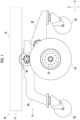
Fig. 1 is a side view of a traveling device according to a first embodiment. -
Fig. 2 is a perspective view of a suspension device of the first embodiment. -
Fig. 3 is a side view of a part of the suspension device of the first embodiment when viewed from the inside in a left-right direction. -
Fig. 4 is a view schematically showing a B-B cross section ofFig. 3 . -
Fig. 5 is a side view of a traveling device according to a second embodiment. -
Fig. 6 is a partial cross-sectional side view showing a part ofFig. 5 . -
Fig. 7 is a partial cross-sectional side view showing a part ofFig. 5 . -
Fig. 8A is a first explanatory diagram regarding the operation of auxiliary wheels,Fig. 8B is a second explanatory diagram thereof, andFig. 8C is a third explanatory diagram thereof. - Embodiments will be described below. The same reference numerals will be given to the same components, and overlapping descriptions will be omitted. In the respective drawings, for convenience of explanation, components are appropriately omitted, enlarged, or reduced. The drawings should be viewed in accordance with the orientation of the reference numerals.
- (First embodiment)
Fig. 1 will be referred to. Atraveling device 10 is an automatic guided vehicle such as an automatic guided vehicle (AGV) or an autonomous mobile robot (AMR). Thetraveling device 10 includes adevice body 12 and asuspension device 14 attached to thedevice body 12. Thedevice body 12 includes aplacement portion 16 for placing an article to be transported. Thedevice body 12 is equipped with a control device (not shown) composed of a computer for controlling the traveling operation of thetraveling device 10, a battery (not shown) that supplies power to the control device and a driving device 20 (to be described below), and the like. -
Figs. 2 ,3 , and4 will be referred to.Fig. 3 is also a view of a part of thesuspension device 14 when viewed from an arrow A inFig. 2 . In the present specification, the positional relationship of the respective components will be described using a front-rear direction X, a left-right direction Y, and an up-down direction Z . The front-rear direction X is a horizontal direction perpendicular to a rotation axis 70 (virtual axis) that is the rotation center of a drive wheel 24 (to be described below), and the left-right direction Y is a horizontal direction perpendicular to the front-rear direction X. The up-down direction Z is the vertical direction. - The
suspension device 14 includes a pair ofwheel sets 18 disposed on both left and right sides, adriving device 20 that drives thedrive wheels 24 of thewheel sets 18, and a wheel base (wheel set support body) 22 that supports each of the pair of wheel sets 18). - Each
wheel set 18 is composed of a plurality of wheels. The plurality of wheels that constitute thewheel set 18 include adrive wheel 24, a first drivenwheel 26 disposed on a front side (a left side inFig. 3 ) which is one side in the front-rear direction X with respect to thedrive wheel 24, and a second drivenwheel 28 disposed on a rear side (a right side inFig. 3 ) which is the other side in the front-rear direction X with respect to thedrive wheel 24. - The
drive wheel 24 is rotatable by power transmitted from thedriving device 20. Thedrive wheel 24 of the present embodiment is a wheel with a tire and includes awheel 30 rotated by thedriving device 20, and atire 32 attached to thewheel 30. The type ofdrive wheel 24 is not particularly limited and may be an integrated wheel or the like. - Each driven
wheel drive wheel 24 without power being transmitted thereto from thedriving device 20. Each drivenwheel wheels wheel 26 of the present embodiment is a front wheel on the front side, and the second drivenwheel 28 is a rear wheel on the rear side. - The
driving device 20 of the present embodiment is a gear motor. A specific example of thedriving device 20 is not particularly limited and may be a motor, an engine, or the like. Thedriving device 20 includes acasing 34 fixed to a bogie link member 38 (to be described below) with a bolt or the like. Thecasing 34 penetrates thebogie link member 38 in the left-right direction Y. Thedriving device 20 is disposed inside thedrive wheel 24 in the left-right direction Y. Thedriving device 20 is fixed to thewheel 30 of thedrive wheel 24 with a bolt or the like and includes anoutput member 36 capable of outputting rotational power. Thedrive wheel 24 is rotated by power being directly transmitted from theoutput member 36. - The pair of
wheel bases 22 is disposed at a distance in the left-right direction Y. Eachwheel base 22 includes abogie link member 38 that supports thedrive wheel 24 and the first drivenwheel 26 and arocker link member 40 that supports the second drivenwheel 28 and thebogie link member 38. Eachlink member wheel base 22 is made of metal such as stainless steel or aluminum. - The
bogie link member 38 is an elongated member that is long in the front-rear direction X. Thebogie link member 38 is connected to the first drivenwheel 26 at one end portion (front end portion) in the front-rear direction X and is connected to thedrive wheel 24 at the other end portion (rear end portion) on the opposite side in the front-rear direction X. The bogielink member 38 is connected to thedrive wheel 24 via thedriving device 20 as mentioned above. - The
bogie link member 38 is oscillatably connected to therocker link member 40 via a first support bearing 42 with relative rotation around afirst oscillation axis 44. Thefirst oscillation axis 44 is a virtual axis serving as an oscillation center of thebogie link member 38. The oscillation herein means that a link member (here, the bogie link member 38) pivots around the oscillation axis when viewed from the left-right direction Y, with the mentioned oscillation axis being the oscillation center. - The first support bearing 42 is, for example, a cross roller bearing. The first support bearing 42 includes a first
outer ring 42a, a firstinner ring 42b, and a plurality of first rolling elements (not shown) that roll on the firstouter ring 42a and the firstinner ring 42b. Thebogie link member 38 has a first accommodating recessedportion 46 that is provided at a spot facing therocker link member 40 in the left-right direction Y at an intermediate portion in the front-rear direction X and is recessed in the left-right direction Y. The first support bearing 42 is accommodated in the first accommodating recessedportion 46. The firstouter ring 42a of the first support bearing 42 is fixed to thebogie link member 38 by screws or the like, and the firstinner ring 42b is fixed to therocker link member 40 by screws or the like. Accordingly, the first support bearing 42 oscillatably connects thebogie link member 38 to therocker link member 40. Afirst oscillation axis 44 serving as the oscillation center is provided on an axial center of thefirst support bearing 42. - The
rocker link member 40 is an elongated member that is long in the front-rear direction X. Therocker link member 40 is connected to thebogie link member 38 at one end portion (front end portion) in the front-rear direction X and is connected to the second drivenwheel 28 at the other end portion (rear end portion) on the opposite side in the front-rear direction X. - The
rocker link member 40 is oscillatably connected to thedevice body 12 via a second support bearing 48 with relative rotation around asecond oscillation axis 50. Therocker link member 40 of the present embodiment is connected to thedevice body 12 via anattachment member 52 for attachment to thedevice body 12 in addition to the second support bearing 48. Thesecond oscillation axis 50 is a virtual axis serving as an oscillation center of therocker link member 40. - The second support bearing 48 is, for example, across roller bearing. The second support bearing 48 includes a second
outer ring 48a, a secondinner ring 48b, and a plurality of secondrolling elements 48c that roll on the secondouter ring 48a and the secondinner ring 48b. Therocker link member 40 has a second accommodating recessedportion 54 that is provided at a spot facing theattachment member 52 in the left-right direction Y at an intermediate portion in the front-rear direction X and is recessed in the left-right direction Y. The second support bearing 48 is accommodated in the second accommodating recessedportion 54. The secondouter ring 48a of the second support bearing 48 is fixed to therocker link member 40 by screws or the like, and the secondinner ring 48b is fixed to theattachment member 52 by screws or the like. Accordingly, the second support bearing 48 oscillatably connects therocker link member 40 to thedevice body 12 via theattachment member 52. Thesecond oscillation axis 50 serving as the oscillation center is provided on the axial center of the second support bearing 48. - The
bogie link member 38 and therocker link member 40 of thewheel base 22 constitute a rocker bogie mechanism. The rocker bogie mechanism can oscillate eachlink member oscillation axis surface 56 when traveling on uneven ground with unevenness, undulations, or the like, thereby maintaining a state in which the three wheels (thedrive wheel 24 and the drivenwheels 26 and 28 ) are grounded on the travelingsurface 56. Accordingly, a situation in which any one of the three wheels is lifted from the travelingsurface 56 can be prevented, and high stability can be obtained during traveling on the uneven ground. Since the principle of operation of the rocker bogie mechanism itself is well known, a detailed description thereof will be omitted herein. - The
suspension device 14 includes a pivotingsupport mechanism 62 that supports the drivenwheels pivot axis 60 that extends up and down (in the vertical direction). Thepivot axis 60 is a virtual axis serving as the pivot center of the drivenwheels suspension device 14 of the present embodiment includes individualpivoting support mechanisms 62 corresponding to the first drivenwheel 26 and the second drivenwheel 28, respectively. In the present embodiment, since the pivotingsupport mechanism 62 corresponding to the first drivenwheel 26 and the pivotingsupport mechanism 62 corresponding to the second drivenwheel 28 have the same configuration, the former configuration will be mainly described, and the description of the latter will be omitted. - The pivoting
support mechanism 62 connects the drivenwheel wheel base 22 to be pivotable around thepivot axis 60. The first drivenwheel 26 is connected to thebogie link member 38 of thewheel base 22 by the pivotingsupport mechanism 62. The second drivenwheel 28 is connected to therocker link member 40 of thewheel base 22 by the pivotingsupport mechanism 62. In the present embodiment, the pivotingsupport mechanism 62 and the drivenwheel support mechanism 62 includes awheel support body 64 that supports the drivenwheel 26 so as to be rotatable around the axial center of the drivenwheel rotation connection mechanism 66 that rotatably connects thewheel support body 64 to thewheel base 22. Thewheel support body 64 is configured using, for example, a fork or the like. Therotation connection mechanism 66 of the present embodiment is configured by a rotary joint (swivel joint) . Anaxial center 29 of each drivenwheel pivot axis 60. Accordingly, an intersection point of thepivot axis 60 with respect to the travelingsurface 56 and a grounding point of the drivenwheel device 10, the traveling direction of the travelingdevice 10 and the directions of the drivenwheel -
Fig. 3 will be referred to. A positional relationship between respective components as viewed from the left-right direction Y will be described below. A front-rear dimension from therotation axis 70, which is the rotation center of thedrive wheel 24, to thefirst oscillation axis 44 is defined as La. A front-rear dimension from thefirst oscillation axis 44 to a connection position (thepivot axis 60 of the first drivenwheel 26 in the present embodiment) of the first drivenwheel 26 to thebogie link member 38 is defined as Lb. A front-rear dimension from a connection position (thepivot axis 60 of the second drivenwheel 28 in the present embodiment) of the second drivenwheel 28 to therocker link member 40 to thesecond oscillation axis 50 is defined as Lc. A front-rear dimension from thesecond oscillation axis 50 to thefirst oscillation axis 44 is defined as Ld. A front-rear dimension from thesecond oscillation axis 50 to a connection position of the first drivenwheel 26 to thebogie link member 38 is defined as Le. Although La = Ld is established in the present embodiment, these dimensions may be different from each other. The front-rear dimensions herein refer to dimensions in the front-rear direction X - Upward vertical reaction forces acting on the
wheels surface 56 are defined as Fa, Fb1, and Fb2, respectively. Fa is a vertical reaction force of thedrive wheel 24, Fb1 is a vertical reaction force of the first drivenwheel 26, and Fb2 is a vertical reaction force of the second drivenwheel 28. In a case where the rocker bogie mechanism is used, it is known that the ratios (hereinafter referred to as reaction force ratio) of the respective vertical reaction forces Fa, Fb1, and Fb2 can be controlled depending on the ratios of La:Lb and Lc:Ld (hereinafter referred to as length ratios). - In a case where moments around the
first oscillation axis 44 resulting from the vertical reaction forces Fa and Fb1 acting on thebogie link member 38 are balanced with each other, Fa × La = Fb1 × Lb is established, which is rewritten as La:Lb = Fb1: Fa (A). Additionally, in a case where moments around thesecond oscillation axis 50 resulting from the vertical reaction forces Fa, Fb1, and Fb2 acting on therocker link member 40 are balanced with each other, Fb2 × Lc = (Fa + Fb1) × Ld is established, which can be rewritten as Lc:Ld = (Fa + Fb1) : Fb2 (B). Using the length ratio of the above-mentioned La and the like and the formulas (A) and (B), the reaction force ratio of the vertical reaction forces of therespective wheels - For example, in the present embodiment, La:Lb is 1:2, and Fb1: Fa is 1:2. Additionally, in the present embodiment, Lc:Ld (=La) is 3:1 (as a result, Lc:Le = 1:1), and Fa+Fb1:Fb2 is 3:1. Combining these with each other, the reaction force ratio can be obtained as Fa:Fb1:Fb2=2:1:1.
- In the present embodiment, this reaction force ratio means that when the rocker bogie mechanism is in a balanced state, the vertical reaction force Fb1 and Fb2 acting on the driven
wheels drive wheel 24. This means that when the drivenwheels surface 56, compared to a case where the vertical reaction force Fa and the vertical reaction forces Fb1 and Fb2 are the same, thelink members wheels wheels surface 56. In addition to this, by making the vertical reaction forces Fb1 and Fb2 smaller than the vertical reaction force Fa, thedrive wheel 24 to which power is transmitted from the drivingdevice 20 can lighten the rising motion of the drivenwheels surface 56 while enhancing the traction performance. Consequently, it is possible to enhance the traveling performance on the uneven ground. The uneven ground herein includes slippy spots in addition to spots with unevenness, step, or the like. - In this way, in a case where the rocker bogie mechanism is used, La and the like are set to a predetermined length ratio in design such that a vertical reaction force acts on each
wheel - Here, the
first oscillation axis 44 is not on the same vertical line as therotation axis 70. This means that thefirst oscillation axis 44 is at a position shifted in the front-rear direction X with respect to therotation axis 70. Thefirst oscillation axis 44 of the present embodiment is located closer to the first drivenwheel 26 side than therotation axis 70. This is a condition required for realizing the above-mentioned length ratio regarding La:Lb. - A large load is applied to the first support bearing 42 when riding over the step on the traveling surface, and an increase in the size of the first support bearing 42 is required in order to resist the large load. In a case where the
first oscillation axis 44 is disposed below therotation axis 70 in the vertical direction (the up-down direction Z), thefirst oscillation axis 44 and the first support bearing 42 are too close to the travelingsurface 56, and the dimensions of the first support bearing 42 are restricted. In order to prevent this, thefirst oscillation axis 44 is located above therotation axis 70 in the vertical direction (up-down direction Z). Accordingly, the dimension of the first support bearing 42 is less likely to be restricted by the travelingsurface 56, and the dimension of the first support bearing 42 can be increased. Consequently, it is possible to easily secure the durability required for the first support bearing 42 in order to resist the large load applied when riding over the step. - The
first oscillation axis 44 is located inside the contour of thedrive wheel 24. Thefirst oscillation axis 44 is located radially inward of (rotation axis 70 side) thedrive wheel 24 from an outerperipheral surface 24a of thedrive wheel 24 when viewed in the left-right direction Y. Accordingly, compared to a case where thefirst oscillation axis 44 is located on the first drivenwheel 26 side (a left side of a paper surface ofFig. 3 ) in the front-rear direction X from anend 24b of thedrive wheel 24 on the first drivenwheel 26 side, a distance La from therotation axis 70 to thefirst oscillation axis 44 can be shortened. The shorter the distance La, the shorter the distance Lb required to maintain the length ratio La:Lb. Additionally, simultaneously with this, by shortening these distances La and Lb, a distance Lc required to maintain the Lc:Ld ratio can also be shortened. Consequently, the front-rear dimension of theentire suspension device 14 can be reduced while maintaining a predetermined length ratio regarding La and the like. The expression "can maintain the predetermined length ratio regarding La or the like" means that a targeted reaction force ratio can be maintained with respect to how the reaction force acts on eachwheel - The effects of the
above suspension device 14 will be described. - (A) The
suspension device 14 defines the above-mentioned predetermined positional relationship regarding thedrive wheel 24 and thefirst oscillation axis 44. Thus, in thesuspension device 14 using the rocker bogie mechanism, the front-rear dimension of thesuspension device 14 can be reduced. To realize this, a predetermined length ratio can be maintained regarding La, or the like, as mentioned above. Additionally, in addition to this, as mentioned above, the durability required of the first support bearing 42 can also be secured when riding over the step. - (B) The
suspension device 14 includes the pivotingsupport mechanism 62 that supports the drivenwheels pivot axis 60. Thus, when thesuspension device 14 tries to change the traveling direction, the drivenwheels - The pivoting
support mechanism 62 is individually provided corresponding to each of the first drivenwheel 26 and the second drivenwheel 28. Thus, when the rotation directions of the left andright drive wheels 24 are opposite directions, the vehicle can perform an ultra-pivotal turn. - In addition, the first support bearing 42 that connects the
bogie link member 38 and therocker link member 40 to each other is at a position shifted to the first drivenwheel 26 side in the front-rear direction X with respect to therotation axis 70. Thus, a structure is given in which a part of therocker link member 40 and a part of thebogie link member 38 vertically overlap each other up and down between the first support bearing 42 and therotation axis 70. For this reason, compared to a case where the first support bearing 42 is on the same vertical line as therotation axis 70, the front-rear dimension of theentire suspension device 14 can be reduced. - Next, another feature of the
suspension device 14 of the present embodiment will be described. In the present embodiment, an outer diameter ratio between thedrive wheel 24 and one of the first drivenwheel 26 and the second drivenwheel 28 is 2:1 or more. In the present embodiment, this condition is satisfied between thedrive wheel 24 and the first drivenwheel 26 as well as between thedrive wheel 24 and the second drivenwheel 28. The outer diameter herein means the outer diameter in terms of radius. The outer diameter of thedrive wheel 24 is defined as R24, the outer diameter of the first drivenwheel 26 is defined as R26, and the outer diameter of the second drivenwheel 28 is defined as R28. R24:R26 is 2:1 or more, and R24:R28 is 2:1 or more. - As the outer diameters R26 and R28 of the driven
wheels entire suspension device 14 is increased in order to maintain a predetermined length ratio regarding La and the like. For example, as the outer diameter R26 of the first drivenwheel 26 increases, it is necessary to increase the front-rear dimension of thebogie link member 38 to increase the distance Lb in order to avoid interference with thedrive wheel 24. Along with this, it is necessary to increase the distance La in order to maintain the La:Lb ratio, and it is also necessary to increase the distance Lc in order to maintain the Lc:Ld ratio. As a result, the front-rear dimension of theentire suspension device 14 is increased. - Additionally, as the outer diameter R28 of the second driven
wheel 28 increases, it is necessary to increase the front-rear dimension of therocker link member 40 to increase the distance Lc in order to avoid interference with thedrive wheel 24. Along with this, it is necessary to increase the distances La (= Ld) and Lb in order to maintain the Lc:Ld ratio and the La: Lb ratio. As a result, the front-rear dimension of theentire suspension device 14 is increased. - In this regard, by satisfying the above-mentioned condition regarding the outer diameter ratio, compared to a case where the condition is not satisfied, it is possible to reduce the front-rear dimension of the
entire suspension device 14 while maintaining a predetermined length ratio regarding La and the like. In addition, although the upper limit of the outer diameter ratio between a driven wheel and thedrive wheel 24 is not particularly limited, the upper limit may be, for example, 3 to 4:1 or less. - (Second Embodiment)
Figs. 5 and6 will be referred to. The travelingdevice 10 of the present embodiment is different from that of the first embodiment mainly in a configuration around the first drivenwheel 26. Since the configuration around the second drivenwheel 28 is the same as that of the first embodiment, the description thereof will be omitted herein. In a case where there is a drivenwheel 26 to which power is not transmitted from the drivingdevice 20 in the rocker bogie mechanism, the drivenwheel 26 makes it difficult to ride on thestep 80 on the travelingsurface 56. In the following, devised points for making it easier to ride on thestep 80 will be described. -
Figs. 6 and7 will be referred to. Thesuspension device 14 includes alifting support mechanism 82 that liftably supports the first drivenwheel 26. The liftingsupport mechanism 82 liftably connects the first drivenwheel 26 to thewheel base 22. The liftingsupport mechanism 82 includes awheel support body 64 that rotatably supports the first drivenwheel 26 around theaxial center 29 of the first drivenwheel 26, and alifting connection mechanism 84 that liftably connects thewheel support body 64 to thewheel base 22. - The
lifting connection mechanism 84 of the present embodiment includes a linear motion bearing 86 attached to the wheel base 22 (bogie link member 38 in the present embodiment) , and ashaft 88 attached to thewheel support body 64. The linear motion bearing 86 supports theshaft 88 linearly movably. The linear motion bearing 86 and theshaft 88 of the present embodiment constitute a ball spline. Theshaft 88 constituting the ball spline is a spline shaft including a plurality of splines. The linear motion bearing 86 constituting the ball spline includes anouter cylinder 86a attached to thewheel base 22, and a plurality of balls (not shown) disposed between the splines of theshaft 88 and theouter cylinder 86a. The linear motion bearing 86 supports theshaft 88 non-rotatably and linearly movably in the axial direction by balls (not shown) rolling on theouter cylinder 86a and theshaft 88. The first drivenwheel 26 can be liftably supported with the movement of thewheel support body 64 in the up-down direction Z by the abovelifting support mechanism 82. - An
impact absorbing member 90 such as a compression spring is disposed between thewheel base 22 and thewheel support body 64. The load of thedevice body 12 and thewheel base 22 is transmitted to thewheel support body 64 and the first drivenwheel 26 via theimpact absorbing member 90. When an upward impact load is input to the first drivenwheel 26, the impact load is absorbed by elastically deforming theimpact absorbing member 90. Consequently, the impact load transmitted to thedevice body 12 of the travelingdevice 10 can be alleviated. - The
suspension device 14 includes anauxiliary wheel 92 located upward and away from the flat travelingsurface 56 in a state in which the first drivenwheel 26 is grounded on aflat traveling surface 56. Theauxiliary wheel 92 is disposed inside the first drivenwheel 26 in the left-right direction Y. The outer diameter of theauxiliary wheel 92 of the present embodiment is larger than the outer diameter of the first drivenwheel 26. Theauxiliary wheel 92 is rotatably supported around anaxial center 93 of theauxiliary wheel 92 by thewheel support body 64. The liftingsupport mechanism 82 integrally and liftably supports the first drivenwheel 26 and theauxiliary wheel 92. Theauxiliary wheel 92 protrudes to a side (here, to the front side) opposite to the second drivenwheel 28 in the front-rear direction X (see alsoFig. 5 ) with respect to the first drivenwheel 26. - The pivoting
support mechanism 62 corresponding to the first drivenwheel 26 integrally supports the first drivenwheel 26 and theauxiliary wheel 92 to be pivotable around thepivot axis 60. A part of the pivotingsupport mechanism 62 also serves as the configuration of the liftingsupport mechanism 82. More specifically, thewheel support body 64 and shaft 88 (to be described below) of the pivotingsupport mechanism 62 also serve as the configuration of the liftingsupport mechanism 82. -
Thepivoting support mechanism 62 corresponding to the first drivenwheel 26 includes, as described in the first embodiment, thewheel support body 64 that rotatably supports the first drivenwheel 26 around the axial center of the first drivenwheel 26, and therotation connection mechanism 66 that pivotably connects thewheel support body 64 to thewheel base 22. - The
wheel support body 64 includes a firstwheel support member 104 that supports the first drivenwheel 26, and a secondwheel support member 106 that supports theauxiliary wheel 92. - The first
wheel support member 104 includes afirst fork 104a that supports the first drivenwheel 26, and asecond fork 104b that supports the first fork and is supported by the secondwheel support member 106. The first drivenwheel 26 of the present embodiment is supported by the first fork 140a of the firstwheel support member 104 via anaxle 108. - The second
wheel support member 106 includes a plate-shapedsecond base portion 106a, and a plate-shapedsecond support portion 106b extending downward from thesecond base portion 106a. The firstwheel support member 104 is fixed to thesecond base portion 106a of the secondwheel support member 106. Thesecond support portion 106b supports theauxiliary wheel 92 via anaxle 110. - The
rotation connection mechanism 66 of the present embodiment includes ashaft 88 attached to thewheel base 22, and arotary bearing 112 disposed between theshaft 88 and thewheel support body 64 to rotatably connect thewheel support body 64 to theshaft 88. - The
rotary bearing 112 includes aninner ring 112a, anouter ring 112b, and a plurality of rollingelements 112c that roll on theinner ring 112a and theouter ring 112b. Theshaft 88 of the present embodiment is fixed to theinner ring 112a of therotary bearing 112 via abearing holder 114 mounted on a lower end portion of theshaft 88. Therotary bearing 112 of the present embodiment is accommodated in a recessedportion 64a provided in an upper surface portion of thewheel support body 64, and anouter ring 112b thereof is fixed to an inner peripheral portion of the recessedportion 64a. - The above
pivoting support mechanism 62 pivots the first drivenwheel 26 by pivoting thewheel support body 64 around thepivot axis 60 that extends up and down and passes through the axial center of theshaft 88 with respect to thewheel base 22. The abovepivoting support mechanism 62 integrally supports the first drivenwheel 26 and theauxiliary wheel 92 to be pivotable around thepivot axis 60. - In addition, the
shaft 88 of the pivotingsupport mechanism 62 of the present embodiment also serves as the configuration of the liftingsupport mechanism 82 and is attached to thewheel base 22 via the linear motion bearing 86 used in thelifting support mechanism 82. Theshaft 88 of the pivotingsupport mechanism 62 may be attached to thewheel base 22 so as to be linearly immovable without using the linear motion bearing 86 in a case where theshaft 88 does not also serve as the configuration of the liftingsupport mechanism 82. Additionally, theshaft 88 of the liftingsupport mechanism 82 also serves as the configuration of the pivotingsupport mechanism 62 and is rotatably attached to thewheel support body 64 via the rotary bearing 112 used in the pivotingsupport mechanism 62. Theshaft 88 of the liftingsupport mechanism 82 may be non-rotatably attached to thewheel support body 64 in a case where theshaft 88 does not also serve as the configuration of the pivotingsupport mechanism 62. - The operation regarding the above
auxiliary wheel 92 will be described.Fig. 8A will be referred to.Figs. 8A to 8C schematically show only the positions of the first drivenwheel 26, theauxiliary wheel 92, and thepivot axis 60. A case where the travelingdevice 10 travels with the side opposite to the second drivenwheel 28 with respect to the first driven wheel 26 (here, the front side and a right side of a paper surface ofFig. 8A ) as the traveling direction will be considered. In this case, since theauxiliary wheel 92 protrudes to the side opposite to the second drivenwheel 28 in the front-rear direction X, theauxiliary wheel 92 can ride on thestep 80 on the traveling surface earlier than the first drivenwheel 26 as shown inFig. 8B . In this case, since theauxiliary wheel 92 is located upward and away from the flat travelingsurface 56 as mentioned above, theauxiliary wheel 92 can easily ride on thehigh step 80 compared to a case where theauxiliary wheel 92 is grounded on the travelingsurface 56. - After the
auxiliary wheel 92 rides on thestep 80, when the travelingdevice 10 further travels in the traveling direction, the first drivenwheel 26 can ride on thestep 80 as shown inFig. 8C . As a result, the first drivenwheel 26 and theauxiliary wheel 92 can easily ride on thestep 80 that is higher than the highest step on which the first drivenwheel 26 alone rides. - In addition, when the
auxiliary wheels 92 ride on thestep 80, thelink members Figs. 8A to 8C show that thelink members pivot axis 60. Accordingly, while theauxiliary wheel 92 is riding on thestep 80, although not shown, thedrive wheel 24 and the second drivenwheel 28 are in contact with the travelingsurface 56, and theauxiliary wheel 92 is in contact with thestep 80 on the travelingsurface 56 instead of the first drivenwheel 26. That is, even when theauxiliary wheel 92 rides on thestep 80, a state in which the three wheels (theauxiliary wheel 92, thedrive wheel 24, and the second driven wheel 28) is grounded on the travelingsurface 56 can be maintained. - The effects of the
above suspension device 14 will be described. - (C) The
suspension device 14 includes the liftingsupport mechanism 82 that liftably supports the first drivenwheel 26. Thus, the first drivenwheel 26 can be lifted and lowered to follow thestep 80 of the travelingsurface 56, and the highest height of thestep 80 on which the first drivenwheel 26 can ride can be increased. - (D) The
suspension device 14 includes theauxiliary wheel 92 located away from the travelingsurface 56. Thus, the combination of theauxiliary wheel 92 and the drivenwheel 26 can ride over the step that is higher than the highest step on which the drivenwheel 26 can ride. When the size of the drivenwheel 26 is increased in order to ride over such a high step, the front-rear dimension of theentire suspension device 14 is increased in order to maintain a predetermined length ratio regarding the above-mentioned La and the like. In this regard, according to the present embodiment, it is unnecessary to increase the size of the drivenwheel 26 in order to ride over a high step, and consequently, it is possible to avoid an increase in the front-rear dimension of theentire suspension device 14. - (E) The pivoting
support mechanism 62 of the present embodiment integrally and pivotably supports the first drivenwheel 26 and theauxiliary wheel 92. Thus, when thesuspension device 14 tries to change the traveling direction, the first drivenwheel 26 and theauxiliary wheel 92 can be integrally pivoted with the rudder angles (orientations) of the first drivenwheel 26 and theauxiliary wheel 92 aligned to follow the change. For this reason, regardless of whether thesuspension device 14 is traveling straight or traveling curvedly, theauxiliary wheel 92 can ride on the step with the rudder angles of the first drivenwheel 26 and theauxiliary wheel 92 aligned, and a smooth operation can be maintained before and after theauxiliary wheel 92 rides on the step. - (F) The
lifting support mechanism 82 of the present embodiment integrally and liftably supports the first drivenwheel 26 and theauxiliary wheel 92. Thus, the first drivenwheel 26 and theauxiliary wheel 92 can be integrally lifted and lowered to follow the step on the travelingsurface 56, and the height by which the first drivenwheel 26 and theauxiliary wheel 92 can ride on can be further increased. - Next, modifications of the respective components described so far will be described.
- In the embodiment, an example in which the first driven
wheel 26 is a front wheel on one side (front side) in the front-rear direction X, and the second drivenwheel 28 is a rear wheel on the other side (rear side) in the front-rear direction X will be described. In addition to this, the first drivenwheel 26 may be a rear wheel on one side (rear side) in the front-rear direction X, and the second drivenwheel 28 may be a front wheel on the other side (front side) in the front-rear direction X. - In the first embodiment, an example has been described in which the length ratios of La and the like are set such that the vertical reaction forces Fb1 and Fb2 are smaller than the vertical reaction force Fa. The relationship between the length ratio and the reaction force ratio is not particularly limited. For example, the length ratio of the La and the like may be set such that the vertical reaction forces Fa, Fb1, and Fb2 acting on the
wheels Fig. 3 may be set to 1:1, and Lc (=La):Ld may be set to 1:2. - Additionally, in order to make the vertical reaction forces Fb1 and Fb2 acting on the driven
wheels drive wheel 24, the length ratio of La and the like is not limited to the content of the embodiment. For example, in order to make the vertical reaction force Fb1 of the first drivenwheels 26 smaller than the vertical reaction force Fa of thedrive wheels 24, La:Lb may be 1:X (X is a numerical value exceeding 1). Although X has been described as 2 in the embodiment, X may be any numerical value exceeding 1. Accordingly, Fb1: Fa can be set to 1:X from the formula (A), that is, the vertical reaction force Fb1 can be made smaller than the vertical reaction force Fa. In this case, Lc:Ld may be set to 1+X:1 (which results in Lc:Le being 1:1). Accordingly, Fa:Fb1:Fb2 can be X:1:1 from the formulas (A) and (B). That is, both the vertical reaction forces Fb1 and Fb2 can be made smaller than the vertical reaction force Fa. Here, although an example in which both the vertical reaction forces Fb1 and Fb2 are smaller than the vertical reaction force Fa has been described, the length ratio of La and the like may be set such that at least one of the vertical reaction forces Fb1 and Fb2 is smaller than the vertical reaction force Fa. - The pivoting
support mechanism 62, the liftingsupport mechanism 82, and theauxiliary wheel 92 described in the embodiment are not essential, and thesuspension device 14 may not include one or more of them or all of them. - The pivoting
support mechanism 62 may pivotably support the drivenwheels support mechanism 62 only needs to be provided corresponding to only any one of the first drivenwheel 26 and the second drivenwheel 28. It can also be said that thesuspension device 14 only needs to include the pivotingsupport mechanism 62 that pivotably supports one of the first drivenwheel 26 and the second drivenwheel 28. - The
wheel support body 64 only needs to be capable of rotatably supporting the drivenwheel wheel - An example in which the
lifting support mechanism 82 liftably supports the first drivenwheel 26 has been described. In addition to this, in relation to the above-mentioned effect (C), the liftingsupport mechanism 82 may liftably support the second drivenwheel 28. The liftingsupport mechanism 82 only needs to liftably support one of the first drivenwheel 26 and the second drivenwheel 28. In this case, the items described in the embodiment can be embodied by the content in which the first drivenwheel 26 is replaced with the second drivenwheel 28. - In a case where the linear motion bearing 86 is used for the
lifting connection mechanism 84 of the liftingsupport mechanism 82, a specific example of the linear motion bearing 86 is not particularly limited and may be, for example, a slide bush or the like. In addition to this, thelifting connection mechanism 84 of the liftingsupport mechanism 82 may be a guide mechanism such as a linear guide, in addition to the combination of the linear motion bearing 86 and theshaft 88. - Although an example in which the
wheel support body 64 of the liftingsupport mechanism 82 supports theauxiliary wheel 92 in addition to the drivenwheel 26 has been described, thewheel support body 64 may support only the drivenwheel 26 without supporting theauxiliary wheel 92. Also in this case, the above-mentioned effect (C) can be similarly obtained. Additionally, although an example has been described in which thelifting support mechanism 82 integrally and liftably supports the first drivenwheel 26 and theauxiliary wheel 92, the liftingsupport mechanism 82 may integrally and liftably support the second drivenwheel 28 and theauxiliary wheel 92. - In the first embodiment, an example has been described in which in order to obtain the above-mentioned effect (D), the
auxiliary wheel 92 is provided corresponding to the first drivenwheel 26 and protrudes to the side opposite to the second drivenwheel 28 with respect to the first drivenwheel 26. In order to obtain the same effect, theauxiliary wheel 92 may be provided corresponding to the second drivenwheel 28 and protrude to the side opposite to the first drivenwheel 26 with respect to the second drivenwheel 28. Theauxiliary wheel 92 only needs to protrude, with respect to one of the first drivenwheel 26 and the second drivenwheel 28, to the side opposite to the other driven wheel in the front-rear direction X. In this case, when the travelingdevice 10 travels with the side opposite to the first drivenwheel 26 with respect to the second drivenwheel 28 as the traveling direction, the same effect as the above-mentioned (D) can be obtained. In addition to this, theauxiliary wheels 92 may be individually provided corresponding to the first drivenwheels 26 and the second drivenwheels 28, respectively. - The outer diameter ratio of the
drive wheel 24 to one of the first drivenwheel 26 and the second drivenwheel 28 may be less than 2:1. Additionally, only the outer diameter ratio between thedrive wheel 24 and one of the driven wheels may be 2:1 or more, and the outer diameter ratio between thedrive wheel 24 and the other driven wheel may be less than 2:1. - The above embodiment and modifications are exemplary. The technical ideas in which these are abstracted should not be interpreted as being limited to the contents of the embodiments and modifications. Many design changes such as changes, additions, and deletions of components are possible for the contents of the embodiment and modifications. In the above-mentioned embodiment, the contents that allow such design changes are emphasized with the notation "embodiment" . However, the design changes are allowed even in the contents with no such notation. The hatching given to the cross section of the drawing does not limit the material of a hatched object. Structures/numerical values referred to in the embodiment and modifications naturally include those that can be regarded as the same when manufacturing errors and the like are taken into consideration.
-
- 10:
- traveling device
- 12:
- device body
- 14:
- suspension device
- 24:
- drive wheel
- 26:
- first driven wheel
- 28:
- second driven wheel
- 38:
- bogie link member
- 40:
- rocker link member
- 44:
- first oscillation axis
- 50:
- second oscillation axis
- 56:
- traveling surface
- 60:
- pivot axis
- 62:
- pivoting support mechanism
- 82:
- lifting support mechanism
- 92:
- auxiliary wheel
Claims (8)
- A suspension device (14) comprising:a drive wheel (24);a first driven wheel (26) that is disposed on one side in a front-rear direction with respect to the drive wheel (24);a second driven wheel (28) that is disposed on the other side in the front-rear direction with respect to the drive wheel (24) ;a bogie link member (38) that supports the drive wheel (24) and the first driven wheel (26) and is oscillatable around a first oscillation axis (44); anda rocker link member (40) that supports the second driven wheel (28) and the bogie link member (38) and is oscillatable around a second oscillation axis (50),wherein when viewed from a left-right direction, the first oscillation axis (44) is not on the same vertical line as a rotation axis (70) of the drive wheel (24) and is located above the rotation axis (70) in a vertical direction and located inside a contour of the drive wheel (24).
- The suspension device (14) according to claim 1, further comprising:a pivoting support mechanism (62) that supports one of the first driven wheel (26) and the second driven wheel (28) to be pivotable around a pivot axis (60) that extends up and down.
- The suspension device (14) according to claim 1 or 2, further comprising:
a lifting support mechanism (82) that liftably supports one of the first driven wheel (26) and the second driven wheel (28) . - The suspension device (14) according to any one of claims 1 to 3, further comprising:an auxiliary wheel (92) that is located away from a traveling surface in a state in which one of the first driven wheel (26) and the second driven wheel (28) is grounded on the traveling surface,wherein the auxiliary wheel (92) protrudes to a side opposite to the other of the first driven wheel (26) and the second driven wheel (28) in the front-rear direction with respect to the one driven wheel (26, 28).
- The suspension device (14) according to claim 4, further comprising:
a pivoting support mechanism (62) that supports the one driven wheel (26, 28) and the auxiliary wheel (92) to be pivotable around a pivot axis (60) that integrally extends up and down. - The suspension device (14) according to claim 4 or 5, further comprising:
a lifting support mechanism (82) that integrally and liftably supports the one driven wheel (26, 28) and the auxiliary wheel (92). - The suspension device (14) according to any one of claims 1 to 6,
wherein an outer diameter ratio between the drive wheel (24) and one of the first driven wheel (26) and the second driven wheel (28) is 2:1 or more. - A traveling device (10) comprising:a device body (12); andthe suspension device (14) according to any one of claims 1 to 7, which is attached to the device body (12).
Applications Claiming Priority (1)
| Application Number | Priority Date | Filing Date | Title |
|---|---|---|---|
| JP2021170365A JP7716310B2 (en) | 2021-10-18 | 2021-10-18 | Undercarriage and running gear |
Publications (2)
| Publication Number | Publication Date |
|---|---|
| EP4166347A1 true EP4166347A1 (en) | 2023-04-19 |
| EP4166347B1 EP4166347B1 (en) | 2024-07-24 |
Family
ID=83398180
Family Applications (1)
| Application Number | Title | Priority Date | Filing Date |
|---|---|---|---|
| EP22196455.4A Active EP4166347B1 (en) | 2021-10-18 | 2022-09-20 | Suspension device and traveling device |
Country Status (4)
| Country | Link |
|---|---|
| US (1) | US11731473B2 (en) |
| EP (1) | EP4166347B1 (en) |
| JP (1) | JP7716310B2 (en) |
| CN (1) | CN115991236B (en) |
Families Citing this family (5)
| Publication number | Priority date | Publication date | Assignee | Title |
|---|---|---|---|---|
| WO2025029967A2 (en) * | 2023-07-31 | 2025-02-06 | Karsten Manufacturing Corporation | Multi-wheel casters |
| EP4563517A1 (en) * | 2023-12-01 | 2025-06-04 | Mobile Industrial Robots A/S | Mobile robot braking |
| JP7779453B1 (en) * | 2024-06-10 | 2025-12-03 | 日本精工株式会社 | Wheel structure and vehicle |
| WO2025258136A1 (en) * | 2024-06-10 | 2025-12-18 | 日本精工株式会社 | Wheel structure and vehicle |
| CN119590535A (en) * | 2024-12-31 | 2025-03-11 | 神华准格尔能源有限责任公司 | Walking mechanism and inspection robot having the same |
Citations (5)
| Publication number | Priority date | Publication date | Assignee | Title |
|---|---|---|---|---|
| WO2003034969A1 (en) * | 2001-10-19 | 2003-05-01 | Invacare Corporation | Wheelchair suspension having pivotal motor mount |
| WO2006102781A2 (en) * | 2005-03-31 | 2006-10-05 | Degonda Rehab Sa | Swivel wheel unit and wheelchair comprising at least one swivel wheel unit |
| GB2441318A (en) * | 2006-08-31 | 2008-03-05 | Kwang Yang Motor Co | Electric wheelchair suspension |
| JP2020019348A (en) | 2018-07-31 | 2020-02-06 | 株式会社リコー | Running gear |
| CN113086051A (en) * | 2021-04-30 | 2021-07-09 | 深圳市普渡科技有限公司 | Suspension device, chassis with same and robot |
Family Cites Families (21)
| Publication number | Priority date | Publication date | Assignee | Title |
|---|---|---|---|---|
| FR1599699A (en) * | 1968-02-09 | 1970-07-20 | ||
| SE464614B (en) * | 1988-11-28 | 1991-05-27 | Mercado Medic Ab | WHEELCHAIR WITH SEX WHEEL CHASSIS |
| JPH1159431A (en) * | 1997-08-11 | 1999-03-02 | Mitsubishi Heavy Ind Ltd | Unmanned carrier |
| US6722455B2 (en) * | 2002-02-28 | 2004-04-20 | New Holland North America, Inc. | Oscillating middle axle for a utility vehicle |
| JP5240683B2 (en) * | 2007-06-08 | 2013-07-17 | 独立行政法人 宇宙航空研究開発機構 | Traveling mechanism with rocker crawler |
| CN101407164B (en) * | 2008-11-28 | 2010-11-10 | 哈尔滨工业大学 | Six-wheel planetary exploration vehicle retractable suspension mechanism |
| JP5481994B2 (en) * | 2009-07-24 | 2014-04-23 | 株式会社明電舎 | Traveling cart |
| EP3281848B1 (en) * | 2015-03-24 | 2020-07-15 | Tokyo Metropolitan Industrial Technology Research Institute | Rocker bogie |
| JP6708488B2 (en) * | 2016-06-16 | 2020-06-10 | 株式会社トーキンオール | Rocker bogie mechanism and traveling device |
| CN206569167U (en) * | 2017-03-14 | 2017-10-20 | 天津智汇时代科技有限公司 | A kind of robot with obstacle detouring climbing function |
| DE102017207748A1 (en) * | 2017-05-08 | 2018-11-08 | Fraunhofer-Gesellschaft zur Förderung der angewandten Forschung e.V. | Vehicle for receiving loads |
| CN110709314B (en) * | 2017-07-04 | 2022-06-21 | 投津欧陆股份有限公司 | Rocker arm bogie mechanism and walking device |
| CN107627803B (en) * | 2017-09-29 | 2023-06-20 | 常州中车瑞泰装备科技有限公司 | Automatic guiding vehicle tail end lifting device and automatic guiding vehicle |
| CN207972692U (en) * | 2018-03-15 | 2018-10-16 | 太原科技大学 | Full landform aerial work platform caster device |
| CN108357698A (en) * | 2018-04-10 | 2018-08-03 | 上海海洋大学 | A kind of novel Marsokhod |
| CN209739208U (en) * | 2018-06-28 | 2019-12-06 | 广东嘉腾机器人自动化有限公司 | A kind of AGV chassis structure |
| JP2020151160A (en) * | 2019-03-20 | 2020-09-24 | 豊田市 | Six-wheel type electric vehicle |
| KR102140480B1 (en) * | 2019-10-08 | 2020-08-03 | 주식회사 맥파이온 | Wheel driving device for use of Automated Guided Vehicle |
| JP7375631B2 (en) * | 2020-03-13 | 2023-11-08 | トヨタ自動車株式会社 | tricycle wheeled vehicle |
| CN111824457A (en) * | 2020-07-22 | 2020-10-27 | 曹宇婷 | Independent driving steering system of six-wheel rocker arm unmanned lunar vehicle and design method |
| CN112829966A (en) * | 2021-02-07 | 2021-05-25 | 上海埃依斯航天科技有限公司 | A multipurpose mobile device |
-
2021
- 2021-10-18 JP JP2021170365A patent/JP7716310B2/en active Active
-
2022
- 2022-09-16 CN CN202211126852.6A patent/CN115991236B/en active Active
- 2022-09-20 EP EP22196455.4A patent/EP4166347B1/en active Active
- 2022-10-18 US US17/967,901 patent/US11731473B2/en active Active
Patent Citations (5)
| Publication number | Priority date | Publication date | Assignee | Title |
|---|---|---|---|---|
| WO2003034969A1 (en) * | 2001-10-19 | 2003-05-01 | Invacare Corporation | Wheelchair suspension having pivotal motor mount |
| WO2006102781A2 (en) * | 2005-03-31 | 2006-10-05 | Degonda Rehab Sa | Swivel wheel unit and wheelchair comprising at least one swivel wheel unit |
| GB2441318A (en) * | 2006-08-31 | 2008-03-05 | Kwang Yang Motor Co | Electric wheelchair suspension |
| JP2020019348A (en) | 2018-07-31 | 2020-02-06 | 株式会社リコー | Running gear |
| CN113086051A (en) * | 2021-04-30 | 2021-07-09 | 深圳市普渡科技有限公司 | Suspension device, chassis with same and robot |
Also Published As
| Publication number | Publication date |
|---|---|
| JP7716310B2 (en) | 2025-07-31 |
| CN115991236B (en) | 2026-04-10 |
| US20230122451A1 (en) | 2023-04-20 |
| JP2023060650A (en) | 2023-04-28 |
| EP4166347B1 (en) | 2024-07-24 |
| CN115991236A (en) | 2023-04-21 |
| US11731473B2 (en) | 2023-08-22 |
Similar Documents
| Publication | Publication Date | Title |
|---|---|---|
| EP4166347A1 (en) | Suspension device and traveling device | |
| EP2168847B1 (en) | Automatic guided vehicle drive device | |
| CN216185444U (en) | Four-wheel-drive four-rotation robot wheel train structure | |
| EP2905209A1 (en) | Vehicle | |
| JP5768482B2 (en) | Traveling robot | |
| KR102948421B1 (en) | Movable object | |
| CN109878597A (en) | An AGV trolley with precision shock-absorbing steering wheel | |
| CN103764476A (en) | Railway vehicle steering truck | |
| CN111619296A (en) | Suspension system for wheel train movement device and automobile | |
| CN114313061A (en) | Movable type monitoring robot chassis structure with double steering mechanisms | |
| CN214928774U (en) | Electric vehicle steering system driven by hub motor and electric vehicle | |
| KR101592352B1 (en) | Active geometry control suspension system | |
| CN221986209U (en) | Double spring double swing arm differential steering wheel mechanism | |
| CN212332811U (en) | Robot chassis and robot | |
| KR20250104307A (en) | Independent steering device having linear actuator and vehicle including the same | |
| CN118457721A (en) | Corner module and vehicle | |
| KR20220016231A (en) | Differential drive and AGV | |
| CN114314433B (en) | An AGV with multi-degree-of-freedom posture adjustment function | |
| CN113525552B (en) | Driving device and AGV with same | |
| CN214420156U (en) | Suspension structure for driving steering wheel by hub motor and electric vehicle | |
| CN212313562U (en) | City rail vehicle transfers changes parallel robot | |
| JP7475523B1 (en) | Running body | |
| CN114454736A (en) | Mobile platform and mobile charging robot | |
| JP7544924B1 (en) | Mobile Device | |
| CN223804836U (en) | A narrow aisle omnidirectional AGV forklift chassis structure |
Legal Events
| Date | Code | Title | Description |
|---|---|---|---|
| PUAI | Public reference made under article 153(3) epc to a published international application that has entered the european phase |
Free format text: ORIGINAL CODE: 0009012 |
|
| STAA | Information on the status of an ep patent application or granted ep patent |
Free format text: STATUS: THE APPLICATION HAS BEEN PUBLISHED |
|
| AK | Designated contracting states |
Kind code of ref document: A1 Designated state(s): AL AT BE BG CH CY CZ DE DK EE ES FI FR GB GR HR HU IE IS IT LI LT LU LV MC MK MT NL NO PL PT RO RS SE SI SK SM TR |
|
| STAA | Information on the status of an ep patent application or granted ep patent |
Free format text: STATUS: REQUEST FOR EXAMINATION WAS MADE |
|
| 17P | Request for examination filed |
Effective date: 20230420 |
|
| RBV | Designated contracting states (corrected) |
Designated state(s): AL AT BE BG CH CY CZ DE DK EE ES FI FR GB GR HR HU IE IS IT LI LT LU LV MC MK MT NL NO PL PT RO RS SE SI SK SM TR |
|
| REG | Reference to a national code |
Ref country code: DE Ref legal event code: R079 Free format text: PREVIOUS MAIN CLASS: B60B0033000000 Ref country code: DE Ref legal event code: R079 Ref document number: 602022004773 Country of ref document: DE Free format text: PREVIOUS MAIN CLASS: B60B0033000000 Ipc: B62D0061120000 |
|
| GRAP | Despatch of communication of intention to grant a patent |
Free format text: ORIGINAL CODE: EPIDOSNIGR1 |
|
| STAA | Information on the status of an ep patent application or granted ep patent |
Free format text: STATUS: GRANT OF PATENT IS INTENDED |
|
| RIC1 | Information provided on ipc code assigned before grant |
Ipc: B60B 33/06 20060101ALI20240219BHEP Ipc: B60G 7/00 20060101ALI20240219BHEP Ipc: B60G 11/14 20060101ALI20240219BHEP Ipc: B60B 33/00 20060101ALI20240219BHEP Ipc: B62D 61/10 20060101ALI20240219BHEP Ipc: B62D 61/12 20060101AFI20240219BHEP |
|
| INTG | Intention to grant announced |
Effective date: 20240304 |
|
| GRAS | Grant fee paid |
Free format text: ORIGINAL CODE: EPIDOSNIGR3 |
|
| GRAA | (expected) grant |
Free format text: ORIGINAL CODE: 0009210 |
|
| STAA | Information on the status of an ep patent application or granted ep patent |
Free format text: STATUS: THE PATENT HAS BEEN GRANTED |
|
| AK | Designated contracting states |
Kind code of ref document: B1 Designated state(s): AL AT BE BG CH CY CZ DE DK EE ES FI FR GB GR HR HU IE IS IT LI LT LU LV MC MK MT NL NO PL PT RO RS SE SI SK SM TR |
|
| REG | Reference to a national code |
Ref country code: GB Ref legal event code: FG4D |
|
| REG | Reference to a national code |
Ref country code: CH Ref legal event code: EP |
|
| REG | Reference to a national code |
Ref country code: IE Ref legal event code: FG4D Ref country code: DE Ref legal event code: R096 Ref document number: 602022004773 Country of ref document: DE |
|
| REG | Reference to a national code |
Ref country code: LT Ref legal event code: MG9D |
|
| REG | Reference to a national code |
Ref country code: NL Ref legal event code: MP Effective date: 20240724 |
|
| PG25 | Lapsed in a contracting state [announced via postgrant information from national office to epo] |
Ref country code: PT Free format text: LAPSE BECAUSE OF FAILURE TO SUBMIT A TRANSLATION OF THE DESCRIPTION OR TO PAY THE FEE WITHIN THE PRESCRIBED TIME-LIMIT Effective date: 20241125 |
|
| REG | Reference to a national code |
Ref country code: AT Ref legal event code: MK05 Ref document number: 1706069 Country of ref document: AT Kind code of ref document: T Effective date: 20240724 |
|
| PG25 | Lapsed in a contracting state [announced via postgrant information from national office to epo] |
Ref country code: NL Free format text: LAPSE BECAUSE OF FAILURE TO SUBMIT A TRANSLATION OF THE DESCRIPTION OR TO PAY THE FEE WITHIN THE PRESCRIBED TIME-LIMIT Effective date: 20240724 |
|
| PG25 | Lapsed in a contracting state [announced via postgrant information from national office to epo] |
Ref country code: PT Free format text: LAPSE BECAUSE OF FAILURE TO SUBMIT A TRANSLATION OF THE DESCRIPTION OR TO PAY THE FEE WITHIN THE PRESCRIBED TIME-LIMIT Effective date: 20241125 Ref country code: NL Free format text: LAPSE BECAUSE OF FAILURE TO SUBMIT A TRANSLATION OF THE DESCRIPTION OR TO PAY THE FEE WITHIN THE PRESCRIBED TIME-LIMIT Effective date: 20240724 |
|
| PG25 | Lapsed in a contracting state [announced via postgrant information from national office to epo] |
Ref country code: NO Free format text: LAPSE BECAUSE OF FAILURE TO SUBMIT A TRANSLATION OF THE DESCRIPTION OR TO PAY THE FEE WITHIN THE PRESCRIBED TIME-LIMIT Effective date: 20241024 |
|
| PG25 | Lapsed in a contracting state [announced via postgrant information from national office to epo] |
Ref country code: GR Free format text: LAPSE BECAUSE OF FAILURE TO SUBMIT A TRANSLATION OF THE DESCRIPTION OR TO PAY THE FEE WITHIN THE PRESCRIBED TIME-LIMIT Effective date: 20241025 Ref country code: FI Free format text: LAPSE BECAUSE OF FAILURE TO SUBMIT A TRANSLATION OF THE DESCRIPTION OR TO PAY THE FEE WITHIN THE PRESCRIBED TIME-LIMIT Effective date: 20240724 Ref country code: PL Free format text: LAPSE BECAUSE OF FAILURE TO SUBMIT A TRANSLATION OF THE DESCRIPTION OR TO PAY THE FEE WITHIN THE PRESCRIBED TIME-LIMIT Effective date: 20240724 |
|
| PG25 | Lapsed in a contracting state [announced via postgrant information from national office to epo] |
Ref country code: BG Free format text: LAPSE BECAUSE OF FAILURE TO SUBMIT A TRANSLATION OF THE DESCRIPTION OR TO PAY THE FEE WITHIN THE PRESCRIBED TIME-LIMIT Effective date: 20240724 |
|
| PG25 | Lapsed in a contracting state [announced via postgrant information from national office to epo] |
Ref country code: LV Free format text: LAPSE BECAUSE OF FAILURE TO SUBMIT A TRANSLATION OF THE DESCRIPTION OR TO PAY THE FEE WITHIN THE PRESCRIBED TIME-LIMIT Effective date: 20240724 |
|
| PG25 | Lapsed in a contracting state [announced via postgrant information from national office to epo] |
Ref country code: IS Free format text: LAPSE BECAUSE OF FAILURE TO SUBMIT A TRANSLATION OF THE DESCRIPTION OR TO PAY THE FEE WITHIN THE PRESCRIBED TIME-LIMIT Effective date: 20241124 Ref country code: AT Free format text: LAPSE BECAUSE OF FAILURE TO SUBMIT A TRANSLATION OF THE DESCRIPTION OR TO PAY THE FEE WITHIN THE PRESCRIBED TIME-LIMIT Effective date: 20240724 |
|
| PG25 | Lapsed in a contracting state [announced via postgrant information from national office to epo] |
Ref country code: HR Free format text: LAPSE BECAUSE OF FAILURE TO SUBMIT A TRANSLATION OF THE DESCRIPTION OR TO PAY THE FEE WITHIN THE PRESCRIBED TIME-LIMIT Effective date: 20240724 |
|
| PG25 | Lapsed in a contracting state [announced via postgrant information from national office to epo] |
Ref country code: ES Free format text: LAPSE BECAUSE OF FAILURE TO SUBMIT A TRANSLATION OF THE DESCRIPTION OR TO PAY THE FEE WITHIN THE PRESCRIBED TIME-LIMIT Effective date: 20240724 Ref country code: RS Free format text: LAPSE BECAUSE OF FAILURE TO SUBMIT A TRANSLATION OF THE DESCRIPTION OR TO PAY THE FEE WITHIN THE PRESCRIBED TIME-LIMIT Effective date: 20241024 |
|
| PG25 | Lapsed in a contracting state [announced via postgrant information from national office to epo] |
Ref country code: RS Free format text: LAPSE BECAUSE OF FAILURE TO SUBMIT A TRANSLATION OF THE DESCRIPTION OR TO PAY THE FEE WITHIN THE PRESCRIBED TIME-LIMIT Effective date: 20241024 Ref country code: PL Free format text: LAPSE BECAUSE OF FAILURE TO SUBMIT A TRANSLATION OF THE DESCRIPTION OR TO PAY THE FEE WITHIN THE PRESCRIBED TIME-LIMIT Effective date: 20240724 Ref country code: NO Free format text: LAPSE BECAUSE OF FAILURE TO SUBMIT A TRANSLATION OF THE DESCRIPTION OR TO PAY THE FEE WITHIN THE PRESCRIBED TIME-LIMIT Effective date: 20241024 Ref country code: LV Free format text: LAPSE BECAUSE OF FAILURE TO SUBMIT A TRANSLATION OF THE DESCRIPTION OR TO PAY THE FEE WITHIN THE PRESCRIBED TIME-LIMIT Effective date: 20240724 Ref country code: IS Free format text: LAPSE BECAUSE OF FAILURE TO SUBMIT A TRANSLATION OF THE DESCRIPTION OR TO PAY THE FEE WITHIN THE PRESCRIBED TIME-LIMIT Effective date: 20241124 Ref country code: HR Free format text: LAPSE BECAUSE OF FAILURE TO SUBMIT A TRANSLATION OF THE DESCRIPTION OR TO PAY THE FEE WITHIN THE PRESCRIBED TIME-LIMIT Effective date: 20240724 Ref country code: GR Free format text: LAPSE BECAUSE OF FAILURE TO SUBMIT A TRANSLATION OF THE DESCRIPTION OR TO PAY THE FEE WITHIN THE PRESCRIBED TIME-LIMIT Effective date: 20241025 Ref country code: FI Free format text: LAPSE BECAUSE OF FAILURE TO SUBMIT A TRANSLATION OF THE DESCRIPTION OR TO PAY THE FEE WITHIN THE PRESCRIBED TIME-LIMIT Effective date: 20240724 Ref country code: ES Free format text: LAPSE BECAUSE OF FAILURE TO SUBMIT A TRANSLATION OF THE DESCRIPTION OR TO PAY THE FEE WITHIN THE PRESCRIBED TIME-LIMIT Effective date: 20240724 Ref country code: BG Free format text: LAPSE BECAUSE OF FAILURE TO SUBMIT A TRANSLATION OF THE DESCRIPTION OR TO PAY THE FEE WITHIN THE PRESCRIBED TIME-LIMIT Effective date: 20240724 Ref country code: AT Free format text: LAPSE BECAUSE OF FAILURE TO SUBMIT A TRANSLATION OF THE DESCRIPTION OR TO PAY THE FEE WITHIN THE PRESCRIBED TIME-LIMIT Effective date: 20240724 |
|
| PG25 | Lapsed in a contracting state [announced via postgrant information from national office to epo] |
Ref country code: SM Free format text: LAPSE BECAUSE OF FAILURE TO SUBMIT A TRANSLATION OF THE DESCRIPTION OR TO PAY THE FEE WITHIN THE PRESCRIBED TIME-LIMIT Effective date: 20240724 Ref country code: RO Free format text: LAPSE BECAUSE OF FAILURE TO SUBMIT A TRANSLATION OF THE DESCRIPTION OR TO PAY THE FEE WITHIN THE PRESCRIBED TIME-LIMIT Effective date: 20240724 Ref country code: DK Free format text: LAPSE BECAUSE OF FAILURE TO SUBMIT A TRANSLATION OF THE DESCRIPTION OR TO PAY THE FEE WITHIN THE PRESCRIBED TIME-LIMIT Effective date: 20240724 |
|
| PG25 | Lapsed in a contracting state [announced via postgrant information from national office to epo] |
Ref country code: MC Free format text: LAPSE BECAUSE OF FAILURE TO SUBMIT A TRANSLATION OF THE DESCRIPTION OR TO PAY THE FEE WITHIN THE PRESCRIBED TIME-LIMIT Effective date: 20240724 Ref country code: EE Free format text: LAPSE BECAUSE OF FAILURE TO SUBMIT A TRANSLATION OF THE DESCRIPTION OR TO PAY THE FEE WITHIN THE PRESCRIBED TIME-LIMIT Effective date: 20240724 |
|
| PG25 | Lapsed in a contracting state [announced via postgrant information from national office to epo] |
Ref country code: CZ Free format text: LAPSE BECAUSE OF FAILURE TO SUBMIT A TRANSLATION OF THE DESCRIPTION OR TO PAY THE FEE WITHIN THE PRESCRIBED TIME-LIMIT Effective date: 20240724 |
|
| REG | Reference to a national code |
Ref country code: DE Ref legal event code: R097 Ref document number: 602022004773 Country of ref document: DE |
|
| PG25 | Lapsed in a contracting state [announced via postgrant information from national office to epo] |
Ref country code: IT Free format text: LAPSE BECAUSE OF FAILURE TO SUBMIT A TRANSLATION OF THE DESCRIPTION OR TO PAY THE FEE WITHIN THE PRESCRIBED TIME-LIMIT Effective date: 20240724 Ref country code: SK Free format text: LAPSE BECAUSE OF FAILURE TO SUBMIT A TRANSLATION OF THE DESCRIPTION OR TO PAY THE FEE WITHIN THE PRESCRIBED TIME-LIMIT Effective date: 20240724 |
|
| PG25 | Lapsed in a contracting state [announced via postgrant information from national office to epo] |
Ref country code: LU Free format text: LAPSE BECAUSE OF NON-PAYMENT OF DUE FEES Effective date: 20240920 |
|
| PLBE | No opposition filed within time limit |
Free format text: ORIGINAL CODE: 0009261 |
|
| STAA | Information on the status of an ep patent application or granted ep patent |
Free format text: STATUS: NO OPPOSITION FILED WITHIN TIME LIMIT |
|
| 26N | No opposition filed |
Effective date: 20250425 |
|
| REG | Reference to a national code |
Ref country code: BE Ref legal event code: MM Effective date: 20240930 |
|
| PG25 | Lapsed in a contracting state [announced via postgrant information from national office to epo] |
Ref country code: BE Free format text: LAPSE BECAUSE OF NON-PAYMENT OF DUE FEES Effective date: 20240930 |
|
| PG25 | Lapsed in a contracting state [announced via postgrant information from national office to epo] |
Ref country code: FR Free format text: LAPSE BECAUSE OF NON-PAYMENT OF DUE FEES Effective date: 20240924 |
|
| PG25 | Lapsed in a contracting state [announced via postgrant information from national office to epo] |
Ref country code: IE Free format text: LAPSE BECAUSE OF NON-PAYMENT OF DUE FEES Effective date: 20240920 |
|
| PG25 | Lapsed in a contracting state [announced via postgrant information from national office to epo] |
Ref country code: SE Free format text: LAPSE BECAUSE OF FAILURE TO SUBMIT A TRANSLATION OF THE DESCRIPTION OR TO PAY THE FEE WITHIN THE PRESCRIBED TIME-LIMIT Effective date: 20240724 |
|
| PGFP | Annual fee paid to national office [announced via postgrant information from national office to epo] |
Ref country code: DE Payment date: 20250730 Year of fee payment: 4 |
|
| PG25 | Lapsed in a contracting state [announced via postgrant information from national office to epo] |
Ref country code: CY Free format text: LAPSE BECAUSE OF FAILURE TO SUBMIT A TRANSLATION OF THE DESCRIPTION OR TO PAY THE FEE WITHIN THE PRESCRIBED TIME-LIMIT; INVALID AB INITIO Effective date: 20220920 |
|
| PG25 | Lapsed in a contracting state [announced via postgrant information from national office to epo] |
Ref country code: HU Free format text: LAPSE BECAUSE OF FAILURE TO SUBMIT A TRANSLATION OF THE DESCRIPTION OR TO PAY THE FEE WITHIN THE PRESCRIBED TIME-LIMIT; INVALID AB INITIO Effective date: 20220920 |