EP4166339A1 - Head cleaning apparatus, inkjet recording apparatus, head cleaning method and program - Google Patents
Head cleaning apparatus, inkjet recording apparatus, head cleaning method and program Download PDFInfo
- Publication number
- EP4166339A1 EP4166339A1 EP22195352.4A EP22195352A EP4166339A1 EP 4166339 A1 EP4166339 A1 EP 4166339A1 EP 22195352 A EP22195352 A EP 22195352A EP 4166339 A1 EP4166339 A1 EP 4166339A1
- Authority
- EP
- European Patent Office
- Prior art keywords
- cleaning
- mode
- nozzle surface
- head
- rub
- Prior art date
- Legal status (The legal status is an assumption and is not a legal conclusion. Google has not performed a legal analysis and makes no representation as to the accuracy of the status listed.)
- Granted
Links
Images





Classifications
-
- B—PERFORMING OPERATIONS; TRANSPORTING
- B41—PRINTING; LINING MACHINES; TYPEWRITERS; STAMPS
- B41J—TYPEWRITERS; SELECTIVE PRINTING MECHANISMS, i.e. MECHANISMS PRINTING OTHERWISE THAN FROM A FORME; CORRECTION OF TYPOGRAPHICAL ERRORS
- B41J2/00—Typewriters or selective printing mechanisms characterised by the printing or marking process for which they are designed
- B41J2/005—Typewriters or selective printing mechanisms characterised by the printing or marking process for which they are designed characterised by bringing liquid or particles selectively into contact with a printing material
- B41J2/01—Ink jet
- B41J2/135—Nozzles
- B41J2/165—Prevention or detection of nozzle clogging, e.g. cleaning, capping or moistening for nozzles
- B41J2/16517—Cleaning of print head nozzles
- B41J2/16535—Cleaning of print head nozzles using wiping constructions
-
- B—PERFORMING OPERATIONS; TRANSPORTING
- B41—PRINTING; LINING MACHINES; TYPEWRITERS; STAMPS
- B41J—TYPEWRITERS; SELECTIVE PRINTING MECHANISMS, i.e. MECHANISMS PRINTING OTHERWISE THAN FROM A FORME; CORRECTION OF TYPOGRAPHICAL ERRORS
- B41J2/00—Typewriters or selective printing mechanisms characterised by the printing or marking process for which they are designed
- B41J2/005—Typewriters or selective printing mechanisms characterised by the printing or marking process for which they are designed characterised by bringing liquid or particles selectively into contact with a printing material
- B41J2/01—Ink jet
- B41J2/135—Nozzles
- B41J2/165—Prevention or detection of nozzle clogging, e.g. cleaning, capping or moistening for nozzles
- B41J2/16505—Caps, spittoons or covers for cleaning or preventing drying out
- B41J2/16508—Caps, spittoons or covers for cleaning or preventing drying out connected with the printer frame
-
- B—PERFORMING OPERATIONS; TRANSPORTING
- B41—PRINTING; LINING MACHINES; TYPEWRITERS; STAMPS
- B41J—TYPEWRITERS; SELECTIVE PRINTING MECHANISMS, i.e. MECHANISMS PRINTING OTHERWISE THAN FROM A FORME; CORRECTION OF TYPOGRAPHICAL ERRORS
- B41J2/00—Typewriters or selective printing mechanisms characterised by the printing or marking process for which they are designed
- B41J2/005—Typewriters or selective printing mechanisms characterised by the printing or marking process for which they are designed characterised by bringing liquid or particles selectively into contact with a printing material
- B41J2/01—Ink jet
- B41J2/135—Nozzles
- B41J2/165—Prevention or detection of nozzle clogging, e.g. cleaning, capping or moistening for nozzles
- B41J2/16517—Cleaning of print head nozzles
- B41J2/1652—Cleaning of print head nozzles by driving a fluid through the nozzles to the outside thereof, e.g. by applying pressure to the inside or vacuum at the outside of the print head
- B41J2/16526—Cleaning of print head nozzles by driving a fluid through the nozzles to the outside thereof, e.g. by applying pressure to the inside or vacuum at the outside of the print head by applying pressure only
-
- B—PERFORMING OPERATIONS; TRANSPORTING
- B41—PRINTING; LINING MACHINES; TYPEWRITERS; STAMPS
- B41J—TYPEWRITERS; SELECTIVE PRINTING MECHANISMS, i.e. MECHANISMS PRINTING OTHERWISE THAN FROM A FORME; CORRECTION OF TYPOGRAPHICAL ERRORS
- B41J2/00—Typewriters or selective printing mechanisms characterised by the printing or marking process for which they are designed
- B41J2/005—Typewriters or selective printing mechanisms characterised by the printing or marking process for which they are designed characterised by bringing liquid or particles selectively into contact with a printing material
- B41J2/01—Ink jet
- B41J2/135—Nozzles
- B41J2/165—Prevention or detection of nozzle clogging, e.g. cleaning, capping or moistening for nozzles
- B41J2/16517—Cleaning of print head nozzles
- B41J2/16535—Cleaning of print head nozzles using wiping constructions
- B41J2002/1655—Cleaning of print head nozzles using wiping constructions with wiping surface parallel with nozzle plate and mounted on reels, e.g. cleaning ribbon cassettes
-
- B—PERFORMING OPERATIONS; TRANSPORTING
- B41—PRINTING; LINING MACHINES; TYPEWRITERS; STAMPS
- B41J—TYPEWRITERS; SELECTIVE PRINTING MECHANISMS, i.e. MECHANISMS PRINTING OTHERWISE THAN FROM A FORME; CORRECTION OF TYPOGRAPHICAL ERRORS
- B41J2/00—Typewriters or selective printing mechanisms characterised by the printing or marking process for which they are designed
- B41J2/005—Typewriters or selective printing mechanisms characterised by the printing or marking process for which they are designed characterised by bringing liquid or particles selectively into contact with a printing material
- B41J2/01—Ink jet
- B41J2/135—Nozzles
- B41J2/165—Prevention or detection of nozzle clogging, e.g. cleaning, capping or moistening for nozzles
- B41J2/16517—Cleaning of print head nozzles
- B41J2002/16573—Cleaning process logic, e.g. for determining type or order of cleaning processes
-
- B—PERFORMING OPERATIONS; TRANSPORTING
- B41—PRINTING; LINING MACHINES; TYPEWRITERS; STAMPS
- B41J—TYPEWRITERS; SELECTIVE PRINTING MECHANISMS, i.e. MECHANISMS PRINTING OTHERWISE THAN FROM A FORME; CORRECTION OF TYPOGRAPHICAL ERRORS
- B41J25/00—Actions or mechanisms not otherwise provided for
- B41J25/304—Bodily-movable mechanisms for print heads or carriages movable towards or from paper surface
Definitions
- the present disclosure relates to a head cleaning apparatus, an inkjet recording apparatus, a head cleaning method, and a program.
- a known inkjet recording apparatus records images by ejecting ink onto desired positions of a recording medium.
- the ink remaining on the nozzle surface may thicken and solidify while blocking part of ink outlets of nozzles. This may cause poor ink ejection.
- a known head maintenance apparatus rubs the nozzle surface by relatively sliding a cloth and the nozzle surface on each other at a predetermined speed (for example, see Japanese patent No. 5857969 ). Such a head maintenance apparatus can remove the ink remaining on the nozzle surface.
- the apparatus removes the remaining ink by uniformly rubbing the nozzle surface.
- the apparatus may therefore unnecessarily damage the water-repellent film formed on the nozzle surface, depending on the state of ink remaining on the nozzle surface. This may decrease the water-repellent property of the nozzle surface.
- the present invention has been conceived in view of the above issue.
- Objects of the present invention include providing a head cleaning apparatus, an inkjet recording apparatus, a head cleaning method, and a program that can appropriately remove ink remaining on the nozzle surface.
- a head cleaning apparatus (20) including: a cleaning unit (21) that includes a cleaning member (211); and a determination unit (40), wherein the head cleaning apparatus is configured to perform a cleaning operation of cleaning a nozzle surface (11a) of an inkjet head (10) with the cleaning member, the nozzle surface having a water-repellent film, wherein the cleaning operation is performed either in a rub mode or a stamp mode, wherein in the rub mode, the cleaning member and the nozzle surface are brought into contact and relatively slid on each other, wherein in the stamp mode, the cleaning member and the nozzle surface are brought into contact and kept still, wherein the determination unit determines which mode is performed, the rub mode or the stamp mode, in the cleaning operation based on a predetermined condition.
- a head cleaning method for a head cleaning apparatus (20) that includes a cleaning unit (21) including a cleaning member (211) and that is configured to perform a cleaning operation of cleaning a nozzle surface (11a) of an inkjet head (10) with the cleaning member, the nozzle surface having a water-repellent film, wherein the cleaning operation is performed either in a rub mode or a stamp mode, wherein in the rub mode, the cleaning member and the nozzle surface are brought into contact and relatively slid on each other, wherein in the stamp mode, the cleaning member and the nozzle surface are brought into contact and kept still, wherein the head cleaning method includes determining which mode is performed, the rub mode or the stamp mode, in the cleaning operation based on a predetermined condition.
- a program for a computer of a head cleaning apparatus (20) that includes a cleaning unit (21) including a cleaning member (211) and that is configured to perform a cleaning operation of cleaning a nozzle surface (11a) of an inkjet head (10) with the cleaning member, the nozzle surface having a water-repellent film, wherein the cleaning operation is performed either in a rub mode or a stamp mode, wherein in the rub mode, the cleaning member and the nozzle surface are brought into contact and relatively slid on each other, and wherein in the stamp mode, the cleaning member and the nozzle surface are brought into contact and kept still, wherein the program causes the computer to determine which mode is performed, the rub mode or the stamp mode, in the cleaning operation based on a predetermined condition.
- the direction in which a cleaning member 211 of a cleaning unit 21 is conveyed is the X direction
- the direction orthogonal to the X direction on the conveyance surface of the cleaning member 211 is the Y direction
- the direction that is orthogonal to the X and Y directions and in which ink is ejected by an inkjet head 10 is the Z direction, as shown in the figures.
- an inkjet recording apparatus 1 includes an inkjet head 10 and a head cleaning apparatus 20.
- the inkjet head 10 ejects ink from nozzles to print letters or form images on recording media, such as paper or fabric.
- the nozzles of the inkjet head 10 have openings that are arranged in the Y direction on the nozzle surface 11a of the nozzle plate 11.
- the nozzle surface 11a is coated with a water-repellent film (ink-repellent film).
- a water-repellent film an organic film made of fluororesin may be mainly used.
- the head cleaning apparatus 20 includes a cleaning unit 21 that has a cleaning member 211 for cleaning (wiping) the nozzle surface 11a.
- the head cleaning apparatus 20 holds the cleaning surface 211a of the cleaning member 211 such that the cleaning surface 211a is parallel with the X-Y plane that is parallel with the nozzle surface.
- the cleaning member 211 is a long material rolled into a roll.
- the cleaning member 211 may be woven/nonwoven fabric or paper.
- the cleaning member 211 is unwound by the unwinding roller 215 and stretched between the supporting rollers 213, 214, thereby forming a cleaning surface 211a at a predetermined position.
- the cleaning surface 211a to which ink adheres is wound up by the winding roller 212.
- a backup member 216 is disposed at the back surface of the cleaning surface 211a.
- the backup member 216 consists of rubber or sponge, for example, to stand against the pushing force of the nozzle surface 11a to the cleaning surface 211a.
- FIG.3 shows a block diagram showing main functional components of the inkjet recording apparatus 1.
- the inkjet recording apparatus 1 includes a controller 40 (hardware processor, determination unit), an inkjet head driver 15, a cleaning unit driver 29, a carriage driver 35, and a recording medium conveyor 55, as shown in FIG.3 .
- the controller 40 sends signals to the respective drivers to control their driving.
- the controller 40 is a processor that centrally controls the overall operation of the inkjet recording apparatus 1.
- the controller 40 includes a central processing unit (CPU) 41, a random access memory (RAM) 42, a read only memory (ROM) 43, and a storage 44.
- CPU central processing unit
- RAM random access memory
- ROM read only memory
- the CPU 41 reads out control programs and setting data stored in the ROM 43 or the storage 44, causes the RAM 42 to store the read-out programs and data, and executes the programs to drive and control the inkjet recording apparatus 1 and to perform various arithmetic processes.
- the RAM 42 provides the CPU 41, which performs various control operations, with a working memory space and stores temporary data.
- the RAM 42 may include a non-volatile memory.
- the ROM 43 stores various control programs to be executed by the CPU 41, setting data, and so forth.
- a rewritable nonvolatile memory e.g. flash memory
- the storage 44 consists of a hard disk drive (HDD). Along with the HDD, a dynamic random access memory (DRAM) may also be used.
- the storage 44 stores programs to be executed by the CPU 41, print jobs (image recording instructions), image data of images to be recorded in accordance with the print jobs, an operating system (OS), and various kinds of print data related to determination conditions to be described later.
- the inkjet head driver 15 sends driving signals to the inkjet head 10 so that the nozzles appropriately eject ink.
- the cleaning unit driver 29 outputs driving signals to a motor or a brake of a moving mechanism that moves the cleaning unit 21 so that the cleaning unit 21 is moved to a position facing the inkjet head 10, which is the target of the cleaning operation.
- the carriage driver 35 outputs driving signals to a motor or a brake of a moving mechanism that moves the inkjet head 10 so that the inkjet head 10 is moved to a position facing the recording medium or to a position facing the cleaning unit 21.
- the recording medium conveyor 55 conveys the recording medium to the conveyance path that faces the inkjet head 10.
- the inkjet head 10 mounted on the carriage is movable in the Y direction.
- the controller 40 controls the inkjet head driver 15, the carriage driver 35, and the recording medium conveyor 55 to perform the recording operation on the recording medium.
- the controller 40 stops the recording operation.
- the controller 40 controls the carriage driver 35 and the cleaning unit driver 29 to dispose the inkjet head 10 at the cleaning position, as shown in FIG.1 and FIG.2 , and to bring the nozzle surface 11a and the cleaning surface 211a into contact.
- the contact between the nozzle surface 11a and the cleaning surface 211a is achieved by the lifting-lowering function of the carriage by the carriage driver 35 or by the lifting-lowering function of the cleaning unit 21 by the cleaning unit driver 29.
- the cleaning unit 21 of the inkjet recording apparatus 1 performs the cleaning operation on the nozzle surface 11a in a rub mode or a stamp mode. Hereinafter, these modes are described.
- the inkjet head 10 and the cleaning unit 21 are controlled to abut each other or separate from each other by lifting/lowering the cleaning unit 21.
- the abutting and separating may be achieved by lifting/lowering the carriage, as described above.
- the rub mode is a mode in which the nozzle surface 11a and the cleaning surface 211a are brought into contact and relatively slid on each other.
- the controller 40 controls the carriage driver 35 or the cleaning unit driver 29 to bring the nozzle surface 11a and the cleaning surface 211a into contact, as shown in FIG.4B and to perform the sliding motion.
- the inkjet head 10 or the cleaning unit 21 is reciprocated in the Y direction.
- the controller 40 separates the nozzle surface 11a and the cleaning surface 211a as shown in FIG.4C .
- the controller 40 then drives the unwinding roller 215 and the winding roller 212 as shown in FIG.4D to wind up the ink-adhered cleaning surface 211a and set a new cleaning surface 211b.
- the cleaning member 211 can remove small ink droplets present in small spaces between warps and wefts.
- the sliding motion may damage (scratch) the water-repellent film of the nozzle surface 11a and decrease the water-repellent property of the film.
- the stamp mode is a mode where the nozzle surface 11a and the cleaning surface 211a are kept still while being in contact with each other.
- the stamp mode is different from the rub mode in that, after the controller 40 brings the nozzle surface 11a and the cleaning surface 211a into contact as shown in FIG.5B , the controller 40 does not perform the sliding motion in the Y direction but keeps the nozzle surface 11a and the cleaning surface 211a still, and then separates the nozzle surface 11a and the cleaning surface 211a as shown in FIG.5C .
- the stamp mode does not relatively slide the nozzle surface 11a and the cleaning member 211 on each other. Therefore, a thickened or further solidified ink may not be sufficiently removed as compared with the rub mode.
- the cleaning member 211 is a woven fabric, small ink droplets present in small spaces between warps and wefts may not be fully removed.
- the stamp mode since the stamp mode does not perform the sliding motion, the stamp mode does not damage the water-repellent film that covers the nozzle surface 11a in removing the remaining ink as compared with the rub mode.
- the stamp mode can appropriately remove the ink.
- the cleaning operation be performed in the rub mode when small ink droplets or thickened ink adhere to the nozzle surface 11a, for example.
- the cleaning operation be performed in the stamp mode when large ink droplets or ink having a relatively low viscosity adhere to the nozzle surface 11a, for example.
- the controller 40 functions as a determination unit that determines which mode is performed, the rub mode or the stamp mode, in the cleaning operation, on the basis of the determination condition(s) as described below.
- the head cleaning apparatus 20 therefore can appropriately remove the ink adhering to the nozzle surface 11a.
- An example of the determination condition is the time elapsed since the time at which the last cleaning operation is performed.
- FIG.6 is a graph showing the relation between the time elapsed since ink adhered to the nozzle surface 11a and the viscosity of the adhering ink. As shown in FIG.6 , the viscosity of ink adhering to the nozzle surface 11a increases as time elapses. This is because discharge products adhere to the ink and the ink becomes dry as time elapses.
- the controller 40 determines to perform the cleaning operation in the rub mode. If the elapsed time is shorter than three hours, the controller 40 determines to perform the cleaning operation in the stamp mode. Thus, the ink adhering to the nozzle surface 11a can be appropriately removed.
- the determination condition may be related to the components of ink ejected from the nozzles.
- the average diameter of titanium oxide (TiO 2 ) as a pigment of white ink is 180 to 300 nanometers and is greater than the average diameter of pigments of YMCK inks that is 50 to 150 nanometers.
- carbon black (CB) as a pigment of black ink is harder than the pigments of YMCK inks.
- the controller 40 determines to perform the cleaning operation in the stamp mode.
- the controller 40 determines to perform the cleaning operation in the rub mode.
- the determination condition may be related to whether the cleaning operation is performed within a predetermined period of time since purging. Although the predetermined period of time may be determined as desired, it is preferable the predetermined period of time be short (right after purging).
- the controller 40 determines to perform the cleaning operation in the stamp mode. If the cleaning operation is performed after the predetermined period of time since purging, the controller 40 determines to perform the cleaning operation in the rub mode. Thus, the ink adhering to the nozzle surface 11a can be appropriately removed.
- the determination condition may be related to a statistic(s) of the coverage of the recording operation after the last cleaning operation.
- the controller 40 determines to perform the cleaning operation in the stamp mode.
- the controller 40 determines to perform the cleaning operation in the rub mode.
- the statistic of the coverage of the recording operation after the last cleaning operation which is referred to by the controller 40, is not limited to the average but may be the mode, the median, or any known statistic.
- the determination condition may be related to the total printing time of the recording operation since the last cleaning operation.
- the controller 40 determines to perform the cleaning operation in the stamp mode.
- the controller 40 determines to perform the cleaning operation in the rub mode.
- the determination condition may be related to the period of time during which the inkjet head 10 is mounted.
- FIG.7 is a graph showing the relation between the period of time during which the inkjet head 10 is mounted and the water-repellent property of the nozzle surface 11a.
- the longer the inkjet head 10 is mounted the lower the water-repellent property of the nozzle surface 11a becomes. Therefore, the ink is more difficult to remove by the stamp mode when the inkjet head 10 has been mounted for a long time, even if the ink adheres to the nozzle surface 11a in the normal way. This is because the longer the inkjet head 10 is mounted, the more number of times of cleaning operation is performed in the rub mode and the water-repellent film receives more damage.
- the controller 40 determines to perform the cleaning operation in the rub mode.
- the controller 40 determines to perform the cleaning operation in the stamp mode.
- the determination condition may be the installation angle of the inkjet head with respect to the horizontal plane when the inkjet head 10 is installed.
- the controller 40 determines to perform the cleaning operation in the rub mode.
- the controller 40 determines to perform the cleaning operation in the stamp mode.
- the controller 40 determines which mode is performed, the rub mode or the stamp mode, in the cleaning operation on the basis of one determination condition.
- the controller 40 may determine the mode on the basis of a combination of determination conditions.
- the controller 40 determines the mode of the cleaning operation on the basis of a combination of conditions in accordance with the determination process.
- the determination process is described on the basis of the flowchart in FIG.8 .
- the controller 40 of the inkjet recording apparatus 1 In response to receiving an instruction to perform the cleaning operation, the controller 40 of the inkjet recording apparatus 1 resets a determination variable ⁇ to zero (Step S101).
- the determination variable ⁇ is for determining which mode is performed in the cleaning operation.
- the controller 40 determines whether the components of ink ejected from the inkjet head 10 (cleaning target) include titanium oxide or carbon black (Step S102).
- Step S102 When determining that neither titanium oxide nor carbon black is included (Step S102: NO), the controller 40 adds 10 to the determination variable ⁇ and proceeds to step S104 (Step S103). When determining that ether titanium oxide or carbon black is included in the ink (Step S102: YES), the controller 40 proceeds to step S104.
- the controller 40 determines whether the period of time during which the inkjet head 10 is mounted is seven months or longer (Step S104).
- Step S104 When determining that the period of time during which the inkjet head 10 is mounted is seven months or longer (Step S104: YES), the controller 40 adds 10 to the determination variable ⁇ and proceeds to step S106 (Step S105). When determining that the period of time during which the inkjet head 10 is mounted is shorter than seven months (Step S104: NO), the controller 40 proceeds to step S106.
- the controller 40 determines whether the time elapsed since the last cleaning operation is three hours or longer (Step S106).
- step S106 When determining that the time elapsed since the last cleaning operation is three hours or longer (step S106: YES), the controller 40 substitutes 20 for the determination variable ⁇ and proceeds to step S108 (Step S107). When determining that the time elapsed since the last cleaning operation is shorter than three hours (Step S106: NO), the controller 40 proceeds to Step S108.
- Step S108 determines whether the determination variable ⁇ is greater than 19 (Step S108).
- Step S108: YES determines whether the determination variable ⁇ is greater than 19
- Step S109: NO the controller 40 sends a signal to perform the cleaning operation on the inkjet head 10 in the stamp mode (Step S110).
- the mode of the cleaning operation can be determined on the basis of a combination of determination conditions.
- the controller 40 determines the mode on the basis of the combination of the determination conditions 1, 2, 6 as an example.
- the combination of determination conditions from among the determination conditions 1 to 7 may be determined as desired.
- the value added to the determination variable ⁇ , the value to be substituted, and the value for determination in the respective steps may be increased or decreased as desired on the basis of the number of determination conditions included in the combination of determination conditions or on the basis of the weighting on the respective determination conditions included in the combination.
- the evaluation results of the cases where the sliding speed was 20 mm/s and the evaluation results of the cases where the sliding speed was 50 mm/s are compared to each other.
- the comparison shows that, when the sliding speed is the same, the shorter contact time between the nozzle surface 11a and the cleaning surface 211a results in the better ink cleaning capability.
- the cleaning member 211 be in contact with the nozzle surface 11a at least for two seconds or longer.
- the sliding speed be slow.
- the yarn constituting the fabric be split yarn having a cross section as shown in FIG.9 .
- the split yarn consists of a combination of two kinds of fibers S1, S2.
- the nylon fiber is used as the fiber S1
- the polyester fiber is used as the fiber S2.
- the split yarn consists of two kinds of fibers S1, S2 made of different materials and is subjected to the process of opening the fibers. As a result, the fibers are split into finer and distorted fibers.
- the split yarn having a fine fiber structure enhances the liquid-absorbing capability of the cleaning member 211.
- the split yarn having distorted fibers also enhances the ink scraping capability of the cleaning surface 211a in the rub mode.
- the cleaning member 211 be configured such that the width W2 of the cleaning member 211 in the Y direction be wider than the width W1 of the nozzle plate 11 having the nozzle surface 11a in the Y direction.
- the motion of the cleaning member 211 can be simplified in both the rub and stamp modes. Specifically, in both modes, the nozzle surface 11a and the cleaning surface 211a are firstly brought into contact; in the rub mode, the sliding is performed from the contact position; in the stamp mode, the cleaning surface 211a and the nozzle surface 11a are kept still at the contact position.
- the cleaning member 211 be configured such that the width W2 of the cleaning member 211 in the Y direction be wider than the total of (i) the width W1 of the nozzle plate 11 having the nozzle surface 11a in the Y direction and (ii) the sliding distance T1 in the Y direction in the rub mode. According to such a configuration, the whole nozzle surface 11a is always in contact with the cleaning member 211 in the sliding motion in the rub mode. This increases the scraping capability of the cleaning member 211.
- the cleaning member 211 is a woven fabric, it is preferable that a dry fabric be used for the cleaning operation. If the cleaning member 211 is wet, the adhesion between the nozzle surface 11a and the cleaning member 211 is likely to increase. Accordingly, the cleaning member 211 may pull out ink from the nozzles and may stain or damage the nozzle surface 11a.
- the inkjet recording apparatus 1 includes the head cleaning apparatus 20 in the above description, this is not the limitation.
- the head cleaning apparatus 20 may be separate from the inkjet recording apparatus 1.
- the ROM 43 is used as a computer-readable medium that stores the programs of the present invention.
- the computer readable medium is not limited to this example.
- nonvolatile memory such as a flash memory
- portable storage medium such as a CD-ROM
- a carrier wave may be used as a medium to provide data of the programs of the present invention via a communication line.
Landscapes
- Ink Jet (AREA)
Abstract
Description
- The present disclosure relates to a head cleaning apparatus, an inkjet recording apparatus, a head cleaning method, and a program.
- A known inkjet recording apparatus records images by ejecting ink onto desired positions of a recording medium. When ejected ink adheres to the nozzle surface of the inkjet head, the ink remaining on the nozzle surface may thicken and solidify while blocking part of ink outlets of nozzles. This may cause poor ink ejection.
- To remove ink remaining on the nozzle surface, a known head maintenance apparatus rubs the nozzle surface by relatively sliding a cloth and the nozzle surface on each other at a predetermined speed (for example, see
Japanese patent No. 5857969 - According to the invention of
JP5857969B - The present invention has been conceived in view of the above issue. Objects of the present invention include providing a head cleaning apparatus, an inkjet recording apparatus, a head cleaning method, and a program that can appropriately remove ink remaining on the nozzle surface.
- To achieve at least one of the abovementioned objects, according to an aspect of the present invention, there is provided A head cleaning apparatus (20) including: a cleaning unit (21) that includes a cleaning member (211); and a determination unit (40), wherein the head cleaning apparatus is configured to perform a cleaning operation of cleaning a nozzle surface (11a) of an inkjet head (10) with the cleaning member, the nozzle surface having a water-repellent film, wherein the cleaning operation is performed either in a rub mode or a stamp mode, wherein in the rub mode, the cleaning member and the nozzle surface are brought into contact and relatively slid on each other, wherein in the stamp mode, the cleaning member and the nozzle surface are brought into contact and kept still, wherein the determination unit determines which mode is performed, the rub mode or the stamp mode, in the cleaning operation based on a predetermined condition.
- According to another aspect of the present invention, there is provided a head cleaning method for a head cleaning apparatus (20) that includes a cleaning unit (21) including a cleaning member (211) and that is configured to perform a cleaning operation of cleaning a nozzle surface (11a) of an inkjet head (10) with the cleaning member, the nozzle surface having a water-repellent film, wherein the cleaning operation is performed either in a rub mode or a stamp mode, wherein in the rub mode, the cleaning member and the nozzle surface are brought into contact and relatively slid on each other, wherein in the stamp mode, the cleaning member and the nozzle surface are brought into contact and kept still, wherein the head cleaning method includes determining which mode is performed, the rub mode or the stamp mode, in the cleaning operation based on a predetermined condition.
- According to another aspect of the present invention, there is provided a program for a computer of a head cleaning apparatus (20) that includes a cleaning unit (21) including a cleaning member (211) and that is configured to perform a cleaning operation of cleaning a nozzle surface (11a) of an inkjet head (10) with the cleaning member, the nozzle surface having a water-repellent film, wherein the cleaning operation is performed either in a rub mode or a stamp mode, wherein in the rub mode, the cleaning member and the nozzle surface are brought into contact and relatively slid on each other, and wherein in the stamp mode, the cleaning member and the nozzle surface are brought into contact and kept still, wherein the program causes the computer to determine which mode is performed, the rub mode or the stamp mode, in the cleaning operation based on a predetermined condition.
- The advantages and features provided by one or more embodiments of the invention will become more fully understood from the detailed description given hereinbelow and the appended drawings which are given by way of illustration only, and thus are not intended as a definition of the limits of the present invention, wherein:
-
FIG.1 is a front view of an inkjet head and a cleaning unit of an inkjet recording apparatus according to an embodiment of the present invention; -
FIG.2 is a lateral view of the inkjet head and the cleaning unit of the inkjet recording apparatus according to the embodiment of the present invention; -
FIG.3 is a block diagram showing main functional components of the inkjet recording apparatus according to the embodiment of the present invention; -
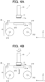
FIG.4A is a lateral view of the inkjet head and the head cleaning apparatus in part of motion in a rub mode; -
FIG.4B is a lateral view of the inkjet head and the head cleaning apparatus in part of motion in the rub mode; -
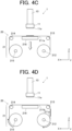
FIG.4C is a lateral view of the inkjet head and the head cleaning apparatus in part of motion in the rub mode; -
FIG.4D is a lateral view of the inkjet head and the head cleaning apparatus in part of motion in the rub mode; -
FIG.5A is a lateral view of the inkjet head and the head cleaning apparatus in part of motion in a stamp mode; -
FIG.5B is a lateral view of the inkjet head and the head cleaning apparatus in part of motion in the stamp mode; -
FIG.5C is a lateral view of the inkjet head and the head cleaning apparatus in part of motion in the stamp mode; -
FIG.5D is a lateral view of the inkjet head and the head cleaning apparatus in part of motion in the stamp mode; -
FIG.6 is a graph showing the relation between the time elapsed since ink adhesion to the nozzle surface and the ink viscosity; -
FIG.7 is a graph showing the relation between the time during which the inkjet head is mounted and the water-repellent property of the nozzle surface; -
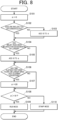
FIG.8 is a flowchart showing a determination process by the controller to determine which mode of cleaning operation is performed based on multiple conditions; and -
FIG.9 shows a schematic cross section of split yarn. - Hereinafter, a preferred embodiment of the present invention is described with reference to the drawings. However, the scope of the invention is not limited to the illustrated examples. In the following description, components having the same function and configuration are marked with the same reference numeral, and the description thereof is omitted.
- In the following description, the direction in which a
cleaning member 211 of acleaning unit 21 is conveyed is the X direction, the direction orthogonal to the X direction on the conveyance surface of thecleaning member 211 is the Y direction, and the direction that is orthogonal to the X and Y directions and in which ink is ejected by aninkjet head 10 is the Z direction, as shown in the figures. - As shown in
FIG.1 and FIG.2 , aninkjet recording apparatus 1 includes aninkjet head 10 and ahead cleaning apparatus 20. - The
inkjet head 10 ejects ink from nozzles to print letters or form images on recording media, such as paper or fabric. The nozzles of theinkjet head 10 have openings that are arranged in the Y direction on thenozzle surface 11a of thenozzle plate 11. - The
nozzle surface 11a is coated with a water-repellent film (ink-repellent film). As the water-repellent film, an organic film made of fluororesin may be mainly used. By coating thenozzle surface 11a with the water-repellent film, the ink is less adhesive to thenozzle surface 11a. - The
head cleaning apparatus 20 includes acleaning unit 21 that has acleaning member 211 for cleaning (wiping) thenozzle surface 11a. Thehead cleaning apparatus 20 holds thecleaning surface 211a of thecleaning member 211 such that thecleaning surface 211a is parallel with the X-Y plane that is parallel with the nozzle surface. - In this embodiment, the
cleaning member 211 is a long material rolled into a roll. For example, thecleaning member 211 may be woven/nonwoven fabric or paper. Thecleaning member 211 is unwound by theunwinding roller 215 and stretched between the supportingrollers cleaning surface 211a at a predetermined position. After cleaning thenozzle surface 11a, thecleaning surface 211a to which ink adheres is wound up by the windingroller 212. At the back surface of thecleaning surface 211a, abackup member 216 is disposed. Thebackup member 216 consists of rubber or sponge, for example, to stand against the pushing force of thenozzle surface 11a to thecleaning surface 211a. -
FIG.3 shows a block diagram showing main functional components of theinkjet recording apparatus 1. - The
inkjet recording apparatus 1 includes a controller 40 (hardware processor, determination unit), aninkjet head driver 15, acleaning unit driver 29, acarriage driver 35, and arecording medium conveyor 55, as shown inFIG.3 . Thecontroller 40 sends signals to the respective drivers to control their driving. - The
controller 40 is a processor that centrally controls the overall operation of theinkjet recording apparatus 1. Thecontroller 40 includes a central processing unit (CPU) 41, a random access memory (RAM) 42, a read only memory (ROM) 43, and astorage 44. - The
CPU 41 reads out control programs and setting data stored in theROM 43 or thestorage 44, causes theRAM 42 to store the read-out programs and data, and executes the programs to drive and control theinkjet recording apparatus 1 and to perform various arithmetic processes. - The
RAM 42 provides theCPU 41, which performs various control operations, with a working memory space and stores temporary data. TheRAM 42 may include a non-volatile memory. - The
ROM 43 stores various control programs to be executed by theCPU 41, setting data, and so forth. Instead of theROM 43, a rewritable nonvolatile memory (e.g. flash memory) may be used. - The
storage 44 consists of a hard disk drive (HDD). Along with the HDD, a dynamic random access memory (DRAM) may also be used. Thestorage 44 stores programs to be executed by theCPU 41, print jobs (image recording instructions), image data of images to be recorded in accordance with the print jobs, an operating system (OS), and various kinds of print data related to determination conditions to be described later. - In accordance with the control signals sent from the
controller 40, theinkjet head driver 15 sends driving signals to theinkjet head 10 so that the nozzles appropriately eject ink. - In accordance with the control signals sent from the
controller 40, thecleaning unit driver 29 outputs driving signals to a motor or a brake of a moving mechanism that moves thecleaning unit 21 so that thecleaning unit 21 is moved to a position facing theinkjet head 10, which is the target of the cleaning operation. - In accordance with the control signals sent from the
controller 40, thecarriage driver 35 outputs driving signals to a motor or a brake of a moving mechanism that moves theinkjet head 10 so that theinkjet head 10 is moved to a position facing the recording medium or to a position facing thecleaning unit 21. - In accordance with the control signals sent from the
controller 40, therecording medium conveyor 55 conveys the recording medium to the conveyance path that faces theinkjet head 10. - The
inkjet head 10 mounted on the carriage is movable in the Y direction. Thecontroller 40 controls theinkjet head driver 15, thecarriage driver 35, and therecording medium conveyor 55 to perform the recording operation on the recording medium. - On the other hand, when the cleaning operation is performed on the
nozzle surface 11a, thecontroller 40 stops the recording operation. Thecontroller 40 controls thecarriage driver 35 and thecleaning unit driver 29 to dispose theinkjet head 10 at the cleaning position, as shown inFIG.1 and FIG.2 , and to bring thenozzle surface 11a and thecleaning surface 211a into contact. The contact between thenozzle surface 11a and thecleaning surface 211a is achieved by the lifting-lowering function of the carriage by thecarriage driver 35 or by the lifting-lowering function of thecleaning unit 21 by thecleaning unit driver 29. - The
cleaning unit 21 of theinkjet recording apparatus 1 performs the cleaning operation on thenozzle surface 11a in a rub mode or a stamp mode. Hereinafter, these modes are described. - In
FIGs. 4B ,4C ,5B and5C , theinkjet head 10 and thecleaning unit 21 are controlled to abut each other or separate from each other by lifting/lowering thecleaning unit 21. However, the abutting and separating may be achieved by lifting/lowering the carriage, as described above. - The rub mode is a mode in which the
nozzle surface 11a and thecleaning surface 211a are brought into contact and relatively slid on each other. - Specifically, as shown in
FIG.4A , in a state where theinkjet head 10 and thecleaning unit 21 are separate from each other, thecontroller 40 controls thecarriage driver 35 or thecleaning unit driver 29 to bring thenozzle surface 11a and thecleaning surface 211a into contact, as shown inFIG.4B and to perform the sliding motion. In the sliding motion, theinkjet head 10 or thecleaning unit 21 is reciprocated in the Y direction. By the sliding, the ink adhering to thenozzle surface 11a is removed. After the sliding motion, thecontroller 40 separates thenozzle surface 11a and thecleaning surface 211a as shown inFIG.4C . Thecontroller 40 then drives the unwindingroller 215 and the windingroller 212 as shown inFIG.4D to wind up the ink-adheredcleaning surface 211a and set anew cleaning surface 211b. - By the rub mode, a thickened or further solidified ink that has adhered to the
nozzle surface 11a for a certain period of time may be removed. Further, when the cleaningmember 211 is a woven fabric, the cleaningmember 211 can remove small ink droplets present in small spaces between warps and wefts. - On the other hand, the sliding motion may damage (scratch) the water-repellent film of the
nozzle surface 11a and decrease the water-repellent property of the film. - The stamp mode is a mode where the
nozzle surface 11a and thecleaning surface 211a are kept still while being in contact with each other. The stamp mode is different from the rub mode in that, after thecontroller 40 brings thenozzle surface 11a and thecleaning surface 211a into contact as shown inFIG.5B , thecontroller 40 does not perform the sliding motion in the Y direction but keeps thenozzle surface 11a and thecleaning surface 211a still, and then separates thenozzle surface 11a and thecleaning surface 211a as shown inFIG.5C . - Unlike the rub mode, the stamp mode does not relatively slide the
nozzle surface 11a and the cleaningmember 211 on each other. Therefore, a thickened or further solidified ink may not be sufficiently removed as compared with the rub mode. When the cleaningmember 211 is a woven fabric, small ink droplets present in small spaces between warps and wefts may not be fully removed. - On the other hand, since the stamp mode does not perform the sliding motion, the stamp mode does not damage the water-repellent film that covers the
nozzle surface 11a in removing the remaining ink as compared with the rub mode. When a large amount of ink adheres to thenozzle surface 11a and the rub mode is performed for removing the ink, the ink may return into the nozzles. The stamp mode, on the other hand, can appropriately remove the ink. - Therefore, it is preferable that the cleaning operation be performed in the rub mode when small ink droplets or thickened ink adhere to the
nozzle surface 11a, for example. - On the other hand, it is preferable that the cleaning operation be performed in the stamp mode when large ink droplets or ink having a relatively low viscosity adhere to the
nozzle surface 11a, for example. - In the
inkjet recording apparatus 1 of this embodiment, thecontroller 40 functions as a determination unit that determines which mode is performed, the rub mode or the stamp mode, in the cleaning operation, on the basis of the determination condition(s) as described below. Thehead cleaning apparatus 20 therefore can appropriately remove the ink adhering to thenozzle surface 11a. - An example of the determination condition is the time elapsed since the time at which the last cleaning operation is performed.
-
FIG.6 is a graph showing the relation between the time elapsed since ink adhered to thenozzle surface 11a and the viscosity of the adhering ink. As shown inFIG.6 , the viscosity of ink adhering to thenozzle surface 11a increases as time elapses. This is because discharge products adhere to the ink and the ink becomes dry as time elapses. - Therefore, if the time elapsed since the time at which the last cleaning operation is performed is three hours or longer, the
controller 40 as the determination unit determines to perform the cleaning operation in the rub mode. If the elapsed time is shorter than three hours, thecontroller 40 determines to perform the cleaning operation in the stamp mode. Thus, the ink adhering to thenozzle surface 11a can be appropriately removed. - The determination condition may be related to the components of ink ejected from the nozzles.
- For example, the average diameter of titanium oxide (TiO2) as a pigment of white ink is 180 to 300 nanometers and is greater than the average diameter of pigments of YMCK inks that is 50 to 150 nanometers. Further, carbon black (CB) as a pigment of black ink is harder than the pigments of YMCK inks. When the ink containing such pigments adheres to the
nozzle surface 11a, the rub mode is likely to damage the water-repellent film covering thenozzle surface 11a. - Therefore, when the ink ejected from the
nozzle surface 11a contains titanium oxide or carbon black, for example, thecontroller 40 as the determination unit determines to perform the cleaning operation in the stamp mode. On the other hand, when the ink does not contain titanium oxide or carbon black, thecontroller 40 determines to perform the cleaning operation in the rub mode. Thus, the ink adhering to thenozzle surface 11a can be appropriately removed. - The determination condition may be related to whether the cleaning operation is performed within a predetermined period of time since purging. Although the predetermined period of time may be determined as desired, it is preferable the predetermined period of time be short (right after purging).
- Right after purging, a large amount of ink adheres to the
nozzle surface 11a. When the rub mode is performed on such anozzle surface 11a, the water-repellent film that covers thenozzle surface 11a may be damaged. - Therefore, if the cleaning operation is performed within a predetermined period of time since purging, the
controller 40 as the determination unit determines to perform the cleaning operation in the stamp mode. If the cleaning operation is performed after the predetermined period of time since purging, thecontroller 40 determines to perform the cleaning operation in the rub mode. Thus, the ink adhering to thenozzle surface 11a can be appropriately removed. - The determination condition may be related to a statistic(s) of the coverage of the recording operation after the last cleaning operation.
- Specifically, assume two cases in which the total printing time of the recording operation after the last cleaning operation is the same but the average coverage is greater in one case than in the other case. In the case having the greater average coverage, a more amount of ink adheres to the
nozzle surface 11a. Therefore, for a greater coverage, the stamp mode is performed for removing ink so as not to damage thenozzle surface 11a, as shown in the Table I and Table II.[TABLE I] COVERAGE 10%PRINTING TIME (h) 1 3 5 7 CLEANING OPERATION RUB RUB STAMP STAMP [TABLE II] COVERAGE 30% PRINTING TIME (h) 1 3 5 7 CLEANING OPERATION RUB STAMP STAMP STAMP - That is, when the average coverage of the recording operation after the last cleaning operation is 30% or greater, the
controller 40 as the determination unit determines to perform the cleaning operation in the stamp mode. On the other hand, when the average coverage is less than 30%, thecontroller 40 determines to perform the cleaning operation in the rub mode. Thus, the ink adhering to thenozzle surface 11a can be appropriately removed. - The statistic of the coverage of the recording operation after the last cleaning operation, which is referred to by the
controller 40, is not limited to the average but may be the mode, the median, or any known statistic. - The determination condition may be related to the total printing time of the recording operation since the last cleaning operation.
- Specifically, assume two cases where the statistic of the coverage of the printing operation after the cleaning operation is the same but the total printing time is longer in one case than in the other case. In the case having the longer total printing time, a more amount of ink adheres to the
nozzle surface 11a. Therefore, for a longer total printing time, the ink is removed by the stamp mode so as not to damage thenozzle surface 11a, as shown in the Table I and Table II. - For example, when the total printing time of the recording operation since the last cleaning operation is five hours or longer, the
controller 40 as the determination unit determines to perform the cleaning operation in the stamp mode. When the total printing time is shorter than five hours, thecontroller 40 determines to perform the cleaning operation in the rub mode. Thus, the ink adhering to thenozzle surface 11a can be appropriately removed. - The determination condition may be related to the period of time during which the
inkjet head 10 is mounted. -
FIG.7 is a graph showing the relation between the period of time during which theinkjet head 10 is mounted and the water-repellent property of thenozzle surface 11a. As shown inFIG.7 , the longer theinkjet head 10 is mounted, the lower the water-repellent property of thenozzle surface 11a becomes. Therefore, the ink is more difficult to remove by the stamp mode when theinkjet head 10 has been mounted for a long time, even if the ink adheres to thenozzle surface 11a in the normal way. This is because the longer theinkjet head 10 is mounted, the more number of times of cleaning operation is performed in the rub mode and the water-repellent film receives more damage. - Therefore, for example, when the number of days elapsed since the date on which the
inkjet head 10 is mounted is seven months or more, thecontroller 40 as the determination unit determines to perform the cleaning operation in the rub mode. When the number of days elapsed is less than seven months, thecontroller 40 determines to perform the cleaning operation in the stamp mode. Thus, the ink adhering to thenozzle surface 11a can be appropriately removed. - The determination condition may be the installation angle of the inkjet head with respect to the horizontal plane when the
inkjet head 10 is installed. - Specifically, when the installation angle is steep, the ink adhering to the
nozzle surface 11a after ink ejection or purging drops from thenozzle surface 11a toward the top plate by gravity. Accordingly, a less amount of ink remains on thenozzle surface 11a, and the water-repellent film is less likely to be damaged. Therefore, when the installation angle is steep, the ink I s removed by the rub mode.[TABLE III] INSTALLATION ANGLE (°) 10 30 50 70 CLEANING OPERATION STAMP STAMP RUB RUB - For example, when the installation angle of the
inkjet head 10 with respect to a horizontal plane at the time of installation is 50 degrees or greater, thecontroller 40 as the determination unit determines to perform the cleaning operation in the rub mode. When the installation angle is less than 50 degrees, thecontroller 40 determines to perform the cleaning operation in the stamp mode. Thus, the ink adhering to thenozzle surface 11a can be appropriately removed. - In the above embodiment, the
controller 40 determines which mode is performed, the rub mode or the stamp mode, in the cleaning operation on the basis of one determination condition. However, this is not the limitation. Thecontroller 40 may determine the mode on the basis of a combination of determination conditions. - The
controller 40 determines the mode of the cleaning operation on the basis of a combination of conditions in accordance with the determination process. The determination process is described on the basis of the flowchart inFIG.8 . - In response to receiving an instruction to perform the cleaning operation, the
controller 40 of theinkjet recording apparatus 1 resets a determination variable α to zero (Step S101). The determination variable α is for determining which mode is performed in the cleaning operation. - The
controller 40 determines whether the components of ink ejected from the inkjet head 10 (cleaning target) include titanium oxide or carbon black (Step S102). - When determining that neither titanium oxide nor carbon black is included (Step S102: NO), the
controller 40 adds 10 to the determination variable α and proceeds to step S104 (Step S103). When determining that ether titanium oxide or carbon black is included in the ink (Step S102: YES), thecontroller 40 proceeds to step S104. - The
controller 40 determines whether the period of time during which theinkjet head 10 is mounted is seven months or longer (Step S104). - When determining that the period of time during which the
inkjet head 10 is mounted is seven months or longer (Step S104: YES), thecontroller 40 adds 10 to the determination variable α and proceeds to step S106 (Step S105). When determining that the period of time during which theinkjet head 10 is mounted is shorter than seven months (Step S104: NO), thecontroller 40 proceeds to step S106. - The
controller 40 then determines whether the time elapsed since the last cleaning operation is three hours or longer (Step S106). - When determining that the time elapsed since the last cleaning operation is three hours or longer (step S106: YES), the
controller 40substitutes 20 for the determination variable α and proceeds to step S108 (Step S107). When determining that the time elapsed since the last cleaning operation is shorter than three hours (Step S106: NO), thecontroller 40 proceeds to Step S108. - Lastly, the
controller 40 determines whether the determination variable α is greater than 19 (Step S108). When determining that the determination variable α is greater than 19 (Step S108: YES), thecontroller 40 sends a signal to perform the cleaning operation on theinkjet head 10 in the rub mode (Step S109). When determining that the determination variable α is 19 or less (Step S108: NO), thecontroller 40 sends a signal to perform the cleaning operation on theinkjet head 10 in the stamp mode (Step S110). - As described above, in the present invention, the mode of the cleaning operation can be determined on the basis of a combination of determination conditions.
- In the above description, the
controller 40 determines the mode on the basis of the combination of thedetermination conditions determination conditions 1 to 7 may be determined as desired. The value added to the determination variable α, the value to be substituted, and the value for determination in the respective steps may be increased or decreased as desired on the basis of the number of determination conditions included in the combination of determination conditions or on the basis of the weighting on the respective determination conditions included in the combination. - Next, the evaluation results of preferred configurations in the rub mode of the present invention are described with respect to the contact time and the relative sliding speed between the
nozzle surface 11a and thecleaning surface 211a. Although the present invention is described in detail below on the basis of examples, the present invention is not limited to the examples. - Ink mists were intentionally adhered to the nozzle surfaces 11a of ten inkjet heads 10. Each of the ten inkjet heads 10 was then subjected to the following examination.
-
- (1) The
inkjet head 10 was mounted on AccurioJet KM-1 (manufactured by Konica Minolta, Inc.) as theinkjet recording apparatus 1. - (2) The
cleaning unit 21 performed rubbing (wiping) on the inkjet had 10. The contact time between thenozzle surface 11a and thecleaning unit 21 was set to 2 seconds, 5 seconds, 10 seconds, 15 seconds, or 20 seconds. The relative sliding speed was set to 20 mm/second or 50 mm/second. The sliding distance was set to 6 mm in the respective cases. - (3) The amount of ink adhering to the
nozzle surface 11a after rubbing (wiping) was visually checked and evaluated as "AA: no ink adhered", "BB: a little ink adhered", and "CC: ink adhered". - The result of the examination is shown in Table IV and Table V.
[TABLE IV] SLIDING SPEED: 20mm/s CONTACT TIME (S) 2 5 10 15 20 EVALUATION RESULT AA AA AA BB BB [TABLE V] SLIDING SPEED: 50mm/s CONTACT TIME (S) 2 5 10 15 20 EVALUATION RESULT AA AA BB BB BB - The evaluation results of the cases where the sliding speed was 20 mm/s and the evaluation results of the cases where the sliding speed was 50 mm/s are compared to each other. The comparison shows that, when the sliding speed is the same, the shorter contact time between the
nozzle surface 11a and thecleaning surface 211a results in the better ink cleaning capability. - This is because the
cleaning surface 211a pulls out ink from the nozzles and stains thenozzle surface 11a when the cleaningmember 211 is in contact with thenozzle surface 11a for a long time. - On the other hand, when the contact time is too short, the cleaning motion is not sufficiently performed. It is therefore preferable that the cleaning
member 211 be in contact with thenozzle surface 11a at least for two seconds or longer. - When the sliding speed was 20 mm/s and the contact time was 10 seconds, the evaluation result was "AA". On the other hand, when the sliding speed was 50 mm/s and the contact time was 10 seconds, the evaluation result was "BB". This shows that, when the contact time is the same, the lower sliding speed between the
nozzle surface 11a and the cleaningmember 211 results in the better ink cleaning capability. - This is because the lower sliding speed allows the cleaning
member 211 to sufficiently absorb the ink adhered to thenozzle surface 11a. - When the contact time is kept unchanged and the sliding speed is increased, the number of times of sliding increases and the water-repellent film is more likely to be damaged. It is therefore preferable that the sliding speed be slow.
- When the cleaning
member 211 is woven fabric, it is preferable that the yarn constituting the fabric be split yarn having a cross section as shown inFIG.9 . As shown inFIG.9 , the split yarn consists of a combination of two kinds of fibers S1, S2. The nylon fiber is used as the fiber S1, and the polyester fiber is used as the fiber S2. The split yarn consists of two kinds of fibers S1, S2 made of different materials and is subjected to the process of opening the fibers. As a result, the fibers are split into finer and distorted fibers. - The split yarn having a fine fiber structure enhances the liquid-absorbing capability of the cleaning
member 211. The split yarn having distorted fibers also enhances the ink scraping capability of thecleaning surface 211a in the rub mode. - As shown in
FIG.1 , it is preferable that the cleaningmember 211 be configured such that the width W2 of the cleaningmember 211 in the Y direction be wider than the width W1 of thenozzle plate 11 having thenozzle surface 11a in the Y direction. According to such a configuration, the motion of the cleaningmember 211 can be simplified in both the rub and stamp modes. Specifically, in both modes, thenozzle surface 11a and thecleaning surface 211a are firstly brought into contact; in the rub mode, the sliding is performed from the contact position; in the stamp mode, thecleaning surface 211a and thenozzle surface 11a are kept still at the contact position. - Further, as shown in
FIG.1 , it is preferable that the cleaningmember 211 be configured such that the width W2 of the cleaningmember 211 in the Y direction be wider than the total of (i) the width W1 of thenozzle plate 11 having thenozzle surface 11a in the Y direction and (ii) the sliding distance T1 in the Y direction in the rub mode. According to such a configuration, thewhole nozzle surface 11a is always in contact with the cleaningmember 211 in the sliding motion in the rub mode. This increases the scraping capability of the cleaningmember 211. - When the cleaning
member 211 is a woven fabric, it is preferable that a dry fabric be used for the cleaning operation. If the cleaningmember 211 is wet, the adhesion between thenozzle surface 11a and the cleaningmember 211 is likely to increase. Accordingly, the cleaningmember 211 may pull out ink from the nozzles and may stain or damage thenozzle surface 11a. - Although the
inkjet recording apparatus 1 includes thehead cleaning apparatus 20 in the above description, this is not the limitation. Thehead cleaning apparatus 20 may be separate from theinkjet recording apparatus 1. - In the above description, the
ROM 43 is used as a computer-readable medium that stores the programs of the present invention. However, the computer readable medium is not limited to this example. - As other computer-readable storage media, a nonvolatile memory, such as a flash memory, and a portable storage medium, such as a CD-ROM, may also be used.
- Further, a carrier wave may be used as a medium to provide data of the programs of the present invention via a communication line.
- The detailed configurations, structures, arrangements, control procedure, and orders of steps in the procedure of the
inkjet recording apparatus 1 and thehead cleaning apparatus 20 in the above embodiment can be appropriately modified without departing from the scope of the present invention.
Claims (17)
- A head cleaning apparatus (20) comprising:a cleaning unit (21) that includes a cleaning member (211); anda determination unit (40),wherein the head cleaning apparatus is configured to perform a cleaning operation of cleaning a nozzle surface (11a) of an inkjet head (10) with the cleaning member, the nozzle surface having a water-repellent film,wherein the cleaning operation is performed either in a rub mode or a stamp mode, wherein in the rub mode, the cleaning member and the nozzle surface are brought into contact and relatively slid on each other, wherein in the stamp mode, the cleaning member and the nozzle surface are brought into contact and kept still,wherein the determination unit determines which mode is performed, the rub mode or the stamp mode, in the cleaning operation based on a predetermined condition.
- The head cleaning apparatus according to claim 1, wherein the determination unit determines which mode is performed, based on an elapsed time since a time at which the last cleaning operation is performed.
- The head cleaning apparatus according to claim 1 or 2, wherein the determination unit determines which mode is performed, based on a component of ink ejected from a nozzle having an opening on the nozzle surface.
- The head cleaning apparatus according to any one of claims 1 to 3, wherein the determination unit determines which mode is performed, based on whether a predetermined time has elapsed or not since purging.
- The head cleaning apparatus according to any one of claims 1 to 4, wherein the determination unit determines which mode is performed, based on a statistic of a coverage in printing after the last cleaning operation.
- The head cleaning apparatus according to any one of claims 1 to 5, wherein the determination unit determines which mode is performed, based on a total printing time since the last cleaning operation.
- The head cleaning apparatus according to any one of claims 1 to 6, wherein the determination unit determines which mode is performed, based on a period of time during which the inkjet head is mounted.
- The head cleaning apparatus according to any one of claims 1 to 7, wherein in the rub mode, a time during which the cleaning member and the nozzle surface are in contact with each other is between two seconds and five seconds.
- The head cleaning apparatus according to any one of claims 1 to 8, wherein in the rub mode, the cleaning member and the nozzle surface are relatively slid on each other at a speed equal to or less than 20 mm/second.
- The head cleaning apparatus according to any one of claims 1 to 9, wherein the determination unit determines which mode is performed, based on an installation angle of the inkjet head with respect to a horizontal plane when the inkjet head is installed.
- The head cleaning apparatus according to any one of claims 1 to 10, wherein the cleaning member is a woven fabric made of split yarn.
- The head cleaning apparatus according to any one of claims 1 to 11, wherein a width of the cleaning member in a sliding direction in the rub mode is wider than a width of the nozzle surface in the sliding direction.
- The head cleaning apparatus according to claim 12, wherein the width of the cleaning member in the sliding direction in the rub mode is greater than a total of the width of the nozzle surface and a sliding distance in the sliding direction in the rub mode.
- The head cleaning apparatus according to any one of claims 1 to 13, wherein the cleaning member to be used in the cleaning operation is dry.
- An inkjet recording apparatus (1) comprising:the inkjet head; andthe head cleaning apparatus according to any one of claims 1 to 14.
- A head cleaning method for a head cleaning apparatus (20) that includes a cleaning unit (21) including a cleaning member (211) and that is configured to perform a cleaning operation of cleaning a nozzle surface (11a) of an inkjet head (10) with the cleaning member, the nozzle surface having a water-repellent film,wherein the cleaning operation is performed either in a rub mode or a stamp mode, wherein in the rub mode, the cleaning member and the nozzle surface are brought into contact and relatively slid on each other, wherein in the stamp mode, the cleaning member and the nozzle surface are brought into contact and kept still,wherein the head cleaning method includes determining which mode is performed, the rub mode or the stamp mode, in the cleaning operation based on a predetermined condition.
- A program for a computer of a head cleaning apparatus (20) that includes a cleaning unit (21) including a cleaning member (211) and that is configured to perform a cleaning operation of cleaning a nozzle surface (11a) of an inkjet head (10) with the cleaning member, the nozzle surface having a water-repellent film,wherein the cleaning operation is performed either in a rub mode or a stamp mode, wherein in the rub mode, the cleaning member and the nozzle surface are brought into contact and relatively slid on each other, and wherein in the stamp mode, the cleaning member and the nozzle surface are brought into contact and kept still,wherein the program causes the computer to determine which mode is performed, the rub mode or the stamp mode, in the cleaning operation based on a predetermined condition.
Applications Claiming Priority (1)
| Application Number | Priority Date | Filing Date | Title |
|---|---|---|---|
| JP2021167571A JP7786121B2 (en) | 2021-10-12 | 2021-10-12 | Head cleaning device, inkjet recording device, head cleaning method and program |
Publications (2)
| Publication Number | Publication Date |
|---|---|
| EP4166339A1 true EP4166339A1 (en) | 2023-04-19 |
| EP4166339B1 EP4166339B1 (en) | 2025-08-20 |
Family
ID=83319122
Family Applications (1)
| Application Number | Title | Priority Date | Filing Date |
|---|---|---|---|
| EP22195352.4A Active EP4166339B1 (en) | 2021-10-12 | 2022-09-13 | Head cleaning apparatus, inkjet recording apparatus, head cleaning method and program |
Country Status (3)
| Country | Link |
|---|---|
| US (1) | US12090763B2 (en) |
| EP (1) | EP4166339B1 (en) |
| JP (1) | JP7786121B2 (en) |
Citations (3)
| Publication number | Priority date | Publication date | Assignee | Title |
|---|---|---|---|---|
| JP2005238611A (en) * | 2004-02-26 | 2005-09-08 | Seiko Instruments Inc | Inkjet head cleaning unit and inkjet printer |
| US20080266342A1 (en) * | 2007-04-24 | 2008-10-30 | Hewlett-Packard Development Companylp | Print head wiping |
| JP5857969B2 (en) | 2010-11-04 | 2016-02-10 | コニカミノルタ株式会社 | Head maintenance device and inkjet recording device |
Family Cites Families (9)
| Publication number | Priority date | Publication date | Assignee | Title |
|---|---|---|---|---|
| JP2001260368A (en) * | 2000-03-16 | 2001-09-25 | Konica Corp | Image forming apparatus and image forming method using ink jet recording head |
| US6695429B2 (en) * | 2001-02-12 | 2004-02-24 | Hewlett-Packard Development Company, L.P. | Fluid assisted printhead blotter for an inkjet printer service station |
| JP2017052117A (en) * | 2015-09-07 | 2017-03-16 | セイコーエプソン株式会社 | Liquid ejecting apparatus and cleaning apparatus |
| JP7180306B2 (en) * | 2018-11-19 | 2022-11-30 | コニカミノルタ株式会社 | HEAD CLEANING DEVICE, INKJET IMAGE FORMING APPARATUS, AND CLEANING METHOD |
| JP7326875B2 (en) * | 2019-05-28 | 2023-08-16 | コニカミノルタ株式会社 | CLEANING DEVICE, INKJET IMAGE FORMING APPARATUS, AND CLEANING CONTROL METHOD |
| JP7400393B2 (en) * | 2019-11-25 | 2023-12-19 | コニカミノルタ株式会社 | Inkjet head maintenance device, inkjet recording device, and inkjet head maintenance method |
| JP2021137997A (en) * | 2020-03-03 | 2021-09-16 | 株式会社リコー | Printing method and printing equipment |
| JP2021146623A (en) * | 2020-03-19 | 2021-09-27 | 株式会社リコー | Wiping device, liquid discharge device and wiping method |
| EP3888889B1 (en) * | 2020-03-31 | 2024-02-14 | Ricoh Company, Ltd. | Droplet discharge apparatus, droplet discharge method, and carrier medium |
-
2021
- 2021-10-12 JP JP2021167571A patent/JP7786121B2/en active Active
-
2022
- 2022-09-13 US US17/943,322 patent/US12090763B2/en active Active
- 2022-09-13 EP EP22195352.4A patent/EP4166339B1/en active Active
Patent Citations (3)
| Publication number | Priority date | Publication date | Assignee | Title |
|---|---|---|---|---|
| JP2005238611A (en) * | 2004-02-26 | 2005-09-08 | Seiko Instruments Inc | Inkjet head cleaning unit and inkjet printer |
| US20080266342A1 (en) * | 2007-04-24 | 2008-10-30 | Hewlett-Packard Development Companylp | Print head wiping |
| JP5857969B2 (en) | 2010-11-04 | 2016-02-10 | コニカミノルタ株式会社 | Head maintenance device and inkjet recording device |
Also Published As
| Publication number | Publication date |
|---|---|
| US12090763B2 (en) | 2024-09-17 |
| US20230115268A1 (en) | 2023-04-13 |
| JP7786121B2 (en) | 2025-12-16 |
| EP4166339B1 (en) | 2025-08-20 |
| JP2023057857A (en) | 2023-04-24 |
Similar Documents
| Publication | Publication Date | Title |
|---|---|---|
| EP3689615B1 (en) | Liquid discharge device, and liquid discharge head cleaning device and method | |
| US5838343A (en) | Backup print cartridge for bank of ink-jet printing cartridges | |
| US20080238990A1 (en) | Cleaning apparatus and liquid ejection apparatus and liquid ejection surface cleaning method | |
| US7380903B2 (en) | Inkjet recording apparatus, and ink discharge surface cleaning method and device | |
| WO2015163087A1 (en) | System for maintaining inkjet recording apparatus | |
| EP4166339B1 (en) | Head cleaning apparatus, inkjet recording apparatus, head cleaning method and program | |
| TR201907687U4 (en) | Inkjet printer with printhead cleaning tool. | |
| US7533983B2 (en) | Image forming apparatus | |
| US20160185121A1 (en) | Recovery system for recording head and ink-jet recording apparatus including the same | |
| JP5794658B2 (en) | Inkjet recording device | |
| JP7613006B2 (en) | Inkjet recording device | |
| JP2021030482A (en) | Inkjet recording device | |
| JP6896517B2 (en) | Inkjet recording device and deposition suppression method | |
| CN112440578B (en) | System and method for cleaning printheads | |
| US11135850B2 (en) | Head cleaning device, inkjet image forming apparatus, and cleaning method | |
| JP2005288913A (en) | Image formation device | |
| JP2025088246A (en) | liquid discharge device | |
| JP7463752B2 (en) | Inkjet recording device | |
| EP4477420A1 (en) | Method for maintenance of a print head of an inkjet printer | |
| JP2008188858A (en) | Cleaning unit, recording apparatus and cleaning method | |
| EP4617068A1 (en) | Image forming system, cleaning apparatus, inkjet recording apparatus, and storage medium | |
| US11850860B2 (en) | Cleaning device and image forming apparatus | |
| JPWO2018235561A1 (en) | Ink ejection head maintenance method, ink ejection head maintenance device, and ink ejection device | |
| US11155095B2 (en) | Inkjet recording apparatus and cleaning method of intermediate transfer body | |
| CN209987573U (en) | Nozzle cleaning device |
Legal Events
| Date | Code | Title | Description |
|---|---|---|---|
| PUAI | Public reference made under article 153(3) epc to a published international application that has entered the european phase |
Free format text: ORIGINAL CODE: 0009012 |
|
| STAA | Information on the status of an ep patent application or granted ep patent |
Free format text: STATUS: THE APPLICATION HAS BEEN PUBLISHED |
|
| AK | Designated contracting states |
Kind code of ref document: A1 Designated state(s): AL AT BE BG CH CY CZ DE DK EE ES FI FR GB GR HR HU IE IS IT LI LT LU LV MC MK MT NL NO PL PT RO RS SE SI SK SM TR |
|
| STAA | Information on the status of an ep patent application or granted ep patent |
Free format text: STATUS: REQUEST FOR EXAMINATION WAS MADE |
|
| 17P | Request for examination filed |
Effective date: 20231010 |
|
| RBV | Designated contracting states (corrected) |
Designated state(s): AL AT BE BG CH CY CZ DE DK EE ES FI FR GB GR HR HU IE IS IT LI LT LU LV MC MK MT NL NO PL PT RO RS SE SI SK SM TR |
|
| STAA | Information on the status of an ep patent application or granted ep patent |
Free format text: STATUS: EXAMINATION IS IN PROGRESS |
|
| 17Q | First examination report despatched |
Effective date: 20250407 |
|
| P01 | Opt-out of the competence of the unified patent court (upc) registered |
Free format text: CASE NUMBER: APP_17880/2025 Effective date: 20250411 |
|
| GRAP | Despatch of communication of intention to grant a patent |
Free format text: ORIGINAL CODE: EPIDOSNIGR1 |
|
| STAA | Information on the status of an ep patent application or granted ep patent |
Free format text: STATUS: GRANT OF PATENT IS INTENDED |
|
| GRAS | Grant fee paid |
Free format text: ORIGINAL CODE: EPIDOSNIGR3 |
|
| GRAA | (expected) grant |
Free format text: ORIGINAL CODE: 0009210 |
|
| STAA | Information on the status of an ep patent application or granted ep patent |
Free format text: STATUS: THE PATENT HAS BEEN GRANTED |
|
| INTG | Intention to grant announced |
Effective date: 20250624 |
|
| AK | Designated contracting states |
Kind code of ref document: B1 Designated state(s): AL AT BE BG CH CY CZ DE DK EE ES FI FR GB GR HR HU IE IS IT LI LT LU LV MC MK MT NL NO PL PT RO RS SE SI SK SM TR |
|
| REG | Reference to a national code |
Ref country code: GB Ref legal event code: FG4D |
|
| REG | Reference to a national code |
Ref country code: CH Ref legal event code: EP |
|
| REG | Reference to a national code |
Ref country code: DE Ref legal event code: R096 Ref document number: 602022019703 Country of ref document: DE |
|
| REG | Reference to a national code |
Ref country code: IE Ref legal event code: FG4D |
|
| PGFP | Annual fee paid to national office [announced via postgrant information from national office to epo] |
Ref country code: FR Payment date: 20250930 Year of fee payment: 4 Ref country code: AT Payment date: 20251020 Year of fee payment: 4 |
|
| REG | Reference to a national code |
Ref country code: NL Ref legal event code: MP Effective date: 20250820 |
|
| PG25 | Lapsed in a contracting state [announced via postgrant information from national office to epo] |
Ref country code: IS Free format text: LAPSE BECAUSE OF FAILURE TO SUBMIT A TRANSLATION OF THE DESCRIPTION OR TO PAY THE FEE WITHIN THE PRESCRIBED TIME-LIMIT Effective date: 20251220 |
|
| PGFP | Annual fee paid to national office [announced via postgrant information from national office to epo] |
Ref country code: DE Payment date: 20250930 Year of fee payment: 4 |
|
| PG25 | Lapsed in a contracting state [announced via postgrant information from national office to epo] |
Ref country code: NO Free format text: LAPSE BECAUSE OF FAILURE TO SUBMIT A TRANSLATION OF THE DESCRIPTION OR TO PAY THE FEE WITHIN THE PRESCRIBED TIME-LIMIT Effective date: 20251120 |
|
| REG | Reference to a national code |
Ref country code: LT Ref legal event code: MG9D |
|
| PG25 | Lapsed in a contracting state [announced via postgrant information from national office to epo] |
Ref country code: PT Free format text: LAPSE BECAUSE OF FAILURE TO SUBMIT A TRANSLATION OF THE DESCRIPTION OR TO PAY THE FEE WITHIN THE PRESCRIBED TIME-LIMIT Effective date: 20251222 |
|
| PG25 | Lapsed in a contracting state [announced via postgrant information from national office to epo] |
Ref country code: FI Free format text: LAPSE BECAUSE OF FAILURE TO SUBMIT A TRANSLATION OF THE DESCRIPTION OR TO PAY THE FEE WITHIN THE PRESCRIBED TIME-LIMIT Effective date: 20250820 |
|
| PG25 | Lapsed in a contracting state [announced via postgrant information from national office to epo] |
Ref country code: HR Free format text: LAPSE BECAUSE OF FAILURE TO SUBMIT A TRANSLATION OF THE DESCRIPTION OR TO PAY THE FEE WITHIN THE PRESCRIBED TIME-LIMIT Effective date: 20250820 Ref country code: NL Free format text: LAPSE BECAUSE OF FAILURE TO SUBMIT A TRANSLATION OF THE DESCRIPTION OR TO PAY THE FEE WITHIN THE PRESCRIBED TIME-LIMIT Effective date: 20250820 |
|
| PG25 | Lapsed in a contracting state [announced via postgrant information from national office to epo] |
Ref country code: GR Free format text: LAPSE BECAUSE OF FAILURE TO SUBMIT A TRANSLATION OF THE DESCRIPTION OR TO PAY THE FEE WITHIN THE PRESCRIBED TIME-LIMIT Effective date: 20251121 |
|
| PG25 | Lapsed in a contracting state [announced via postgrant information from national office to epo] |
Ref country code: SE Free format text: LAPSE BECAUSE OF FAILURE TO SUBMIT A TRANSLATION OF THE DESCRIPTION OR TO PAY THE FEE WITHIN THE PRESCRIBED TIME-LIMIT Effective date: 20250820 |
|
| PG25 | Lapsed in a contracting state [announced via postgrant information from national office to epo] |
Ref country code: LV Free format text: LAPSE BECAUSE OF FAILURE TO SUBMIT A TRANSLATION OF THE DESCRIPTION OR TO PAY THE FEE WITHIN THE PRESCRIBED TIME-LIMIT Effective date: 20250820 |
|
| PG25 | Lapsed in a contracting state [announced via postgrant information from national office to epo] |
Ref country code: BG Free format text: LAPSE BECAUSE OF FAILURE TO SUBMIT A TRANSLATION OF THE DESCRIPTION OR TO PAY THE FEE WITHIN THE PRESCRIBED TIME-LIMIT Effective date: 20250820 Ref country code: PL Free format text: LAPSE BECAUSE OF FAILURE TO SUBMIT A TRANSLATION OF THE DESCRIPTION OR TO PAY THE FEE WITHIN THE PRESCRIBED TIME-LIMIT Effective date: 20250820 |
|
| PG25 | Lapsed in a contracting state [announced via postgrant information from national office to epo] |
Ref country code: RS Free format text: LAPSE BECAUSE OF FAILURE TO SUBMIT A TRANSLATION OF THE DESCRIPTION OR TO PAY THE FEE WITHIN THE PRESCRIBED TIME-LIMIT Effective date: 20251120 |
|
| PG25 | Lapsed in a contracting state [announced via postgrant information from national office to epo] |
Ref country code: ES Free format text: LAPSE BECAUSE OF FAILURE TO SUBMIT A TRANSLATION OF THE DESCRIPTION OR TO PAY THE FEE WITHIN THE PRESCRIBED TIME-LIMIT Effective date: 20250820 |
|
| REG | Reference to a national code |
Ref country code: AT Ref legal event code: MK05 Ref document number: 1826940 Country of ref document: AT Kind code of ref document: T Effective date: 20250820 |
|
| PG25 | Lapsed in a contracting state [announced via postgrant information from national office to epo] |
Ref country code: RO Free format text: LAPSE BECAUSE OF FAILURE TO SUBMIT A TRANSLATION OF THE DESCRIPTION OR TO PAY THE FEE WITHIN THE PRESCRIBED TIME-LIMIT Effective date: 20250820 |
|
| PG25 | Lapsed in a contracting state [announced via postgrant information from national office to epo] |
Ref country code: SM Free format text: LAPSE BECAUSE OF FAILURE TO SUBMIT A TRANSLATION OF THE DESCRIPTION OR TO PAY THE FEE WITHIN THE PRESCRIBED TIME-LIMIT Effective date: 20250820 |
|
| PG25 | Lapsed in a contracting state [announced via postgrant information from national office to epo] |
Ref country code: DK Free format text: LAPSE BECAUSE OF FAILURE TO SUBMIT A TRANSLATION OF THE DESCRIPTION OR TO PAY THE FEE WITHIN THE PRESCRIBED TIME-LIMIT Effective date: 20250820 |
|
| PG25 | Lapsed in a contracting state [announced via postgrant information from national office to epo] |
Ref country code: AT Free format text: LAPSE BECAUSE OF FAILURE TO SUBMIT A TRANSLATION OF THE DESCRIPTION OR TO PAY THE FEE WITHIN THE PRESCRIBED TIME-LIMIT Effective date: 20250820 |
|
| PG25 | Lapsed in a contracting state [announced via postgrant information from national office to epo] |
Ref country code: IT Free format text: LAPSE BECAUSE OF FAILURE TO SUBMIT A TRANSLATION OF THE DESCRIPTION OR TO PAY THE FEE WITHIN THE PRESCRIBED TIME-LIMIT Effective date: 20250820 |
|
| PG25 | Lapsed in a contracting state [announced via postgrant information from national office to epo] |
Ref country code: CZ Free format text: LAPSE BECAUSE OF FAILURE TO SUBMIT A TRANSLATION OF THE DESCRIPTION OR TO PAY THE FEE WITHIN THE PRESCRIBED TIME-LIMIT Effective date: 20250820 |
|
| REG | Reference to a national code |
Ref country code: CH Ref legal event code: H13 Free format text: ST27 STATUS EVENT CODE: U-0-0-H10-H13 (AS PROVIDED BY THE NATIONAL OFFICE) Effective date: 20260425 |
|
| PG25 | Lapsed in a contracting state [announced via postgrant information from national office to epo] |
Ref country code: SK Free format text: LAPSE BECAUSE OF FAILURE TO SUBMIT A TRANSLATION OF THE DESCRIPTION OR TO PAY THE FEE WITHIN THE PRESCRIBED TIME-LIMIT Effective date: 20250820 Ref country code: EE Free format text: LAPSE BECAUSE OF FAILURE TO SUBMIT A TRANSLATION OF THE DESCRIPTION OR TO PAY THE FEE WITHIN THE PRESCRIBED TIME-LIMIT Effective date: 20250820 |
|
| PG25 | Lapsed in a contracting state [announced via postgrant information from national office to epo] |
Ref country code: LU Free format text: LAPSE BECAUSE OF NON-PAYMENT OF DUE FEES Effective date: 20250913 |
|
| REG | Reference to a national code |
Ref country code: DE Ref legal event code: R097 Ref document number: 602022019703 Country of ref document: DE |
|
| REG | Reference to a national code |
Ref country code: BE Ref legal event code: MM Effective date: 20250930 |
|
| PLBE | No opposition filed within time limit |
Free format text: ORIGINAL CODE: 0009261 |
|
| STAA | Information on the status of an ep patent application or granted ep patent |
Free format text: STATUS: NO OPPOSITION FILED WITHIN TIME LIMIT |
|
| PG25 | Lapsed in a contracting state [announced via postgrant information from national office to epo] |
Ref country code: MC Free format text: LAPSE BECAUSE OF FAILURE TO SUBMIT A TRANSLATION OF THE DESCRIPTION OR TO PAY THE FEE WITHIN THE PRESCRIBED TIME-LIMIT Effective date: 20250820 Ref country code: LT Free format text: LAPSE BECAUSE OF FAILURE TO SUBMIT A TRANSLATION OF THE DESCRIPTION OR TO PAY THE FEE WITHIN THE PRESCRIBED TIME-LIMIT Effective date: 20250820 |
|
| REG | Reference to a national code |
Ref country code: CH Ref legal event code: L10 Free format text: ST27 STATUS EVENT CODE: U-0-0-L10-L00 (AS PROVIDED BY THE NATIONAL OFFICE) Effective date: 20260701 |
|
| PG25 | Lapsed in a contracting state [announced via postgrant information from national office to epo] |
Ref country code: CH Free format text: LAPSE BECAUSE OF NON-PAYMENT OF DUE FEES Effective date: 20250930 Ref country code: IE Free format text: LAPSE BECAUSE OF NON-PAYMENT OF DUE FEES Effective date: 20250913 Ref country code: BE Free format text: LAPSE BECAUSE OF NON-PAYMENT OF DUE FEES Effective date: 20250930 |
|
| 26N | No opposition filed |
Effective date: 20260521 |