EP4166266A1 - Laminate shaping method - Google Patents
Laminate shaping method Download PDFInfo
- Publication number
- EP4166266A1 EP4166266A1 EP22199342.1A EP22199342A EP4166266A1 EP 4166266 A1 EP4166266 A1 EP 4166266A1 EP 22199342 A EP22199342 A EP 22199342A EP 4166266 A1 EP4166266 A1 EP 4166266A1
- Authority
- EP
- European Patent Office
- Prior art keywords
- laminate
- shaped portion
- metal layer
- forming
- processed side
- Prior art date
- Legal status (The legal status is an assumption and is not a legal conclusion. Google has not performed a legal analysis and makes no representation as to the accuracy of the status listed.)
- Granted
Links
Images




Classifications
-
- B—PERFORMING OPERATIONS; TRANSPORTING
- B23—MACHINE TOOLS; METAL-WORKING NOT OTHERWISE PROVIDED FOR
- B23K—SOLDERING OR UNSOLDERING; WELDING; CLADDING OR PLATING BY SOLDERING OR WELDING; CUTTING BY APPLYING HEAT LOCALLY, e.g. FLAME CUTTING; WORKING BY LASER BEAM
- B23K9/00—Arc welding or cutting
- B23K9/04—Welding for other purposes than joining, e.g. built-up welding
- B23K9/042—Built-up welding on planar surfaces
-
- B—PERFORMING OPERATIONS; TRANSPORTING
- B23—MACHINE TOOLS; METAL-WORKING NOT OTHERWISE PROVIDED FOR
- B23K—SOLDERING OR UNSOLDERING; WELDING; CLADDING OR PLATING BY SOLDERING OR WELDING; CUTTING BY APPLYING HEAT LOCALLY, e.g. FLAME CUTTING; WORKING BY LASER BEAM
- B23K9/00—Arc welding or cutting
- B23K9/04—Welding for other purposes than joining, e.g. built-up welding
- B23K9/044—Built-up welding on three-dimensional surfaces
-
- B—PERFORMING OPERATIONS; TRANSPORTING
- B23—MACHINE TOOLS; METAL-WORKING NOT OTHERWISE PROVIDED FOR
- B23K—SOLDERING OR UNSOLDERING; WELDING; CLADDING OR PLATING BY SOLDERING OR WELDING; CUTTING BY APPLYING HEAT LOCALLY, e.g. FLAME CUTTING; WORKING BY LASER BEAM
- B23K31/00—Processes relevant to this subclass, specially adapted for particular articles or purposes, but not covered by any single one of main groups B23K1/00 - B23K28/00
- B23K31/02—Processes relevant to this subclass, specially adapted for particular articles or purposes, but not covered by any single one of main groups B23K1/00 - B23K28/00 relating to soldering or welding
-
- B—PERFORMING OPERATIONS; TRANSPORTING
- B23—MACHINE TOOLS; METAL-WORKING NOT OTHERWISE PROVIDED FOR
- B23K—SOLDERING OR UNSOLDERING; WELDING; CLADDING OR PLATING BY SOLDERING OR WELDING; CUTTING BY APPLYING HEAT LOCALLY, e.g. FLAME CUTTING; WORKING BY LASER BEAM
- B23K31/00—Processes relevant to this subclass, specially adapted for particular articles or purposes, but not covered by any single one of main groups B23K1/00 - B23K28/00
- B23K31/10—Processes relevant to this subclass, specially adapted for particular articles or purposes, but not covered by any single one of main groups B23K1/00 - B23K28/00 relating to cutting or desurfacing
-
- B—PERFORMING OPERATIONS; TRANSPORTING
- B33—ADDITIVE MANUFACTURING TECHNOLOGY
- B33Y—ADDITIVE MANUFACTURING, i.e. MANUFACTURING OF THREE-DIMENSIONAL [3D] OBJECTS BY ADDITIVE DEPOSITION, ADDITIVE AGGLOMERATION OR ADDITIVE LAYERING, e.g. BY 3D PRINTING, STEREOLITHOGRAPHY OR SELECTIVE LASER SINTERING
- B33Y40/00—Auxiliary operations or equipment, e.g. for material handling
-
- B—PERFORMING OPERATIONS; TRANSPORTING
- B22—CASTING; POWDER METALLURGY
- B22F—WORKING METALLIC POWDER; MANUFACTURE OF ARTICLES FROM METALLIC POWDER; MAKING METALLIC POWDER; APPARATUS OR DEVICES SPECIALLY ADAPTED FOR METALLIC POWDER
- B22F2999/00—Aspects linked to processes or compositions used in powder metallurgy
-
- B—PERFORMING OPERATIONS; TRANSPORTING
- B23—MACHINE TOOLS; METAL-WORKING NOT OTHERWISE PROVIDED FOR
- B23K—SOLDERING OR UNSOLDERING; WELDING; CLADDING OR PLATING BY SOLDERING OR WELDING; CUTTING BY APPLYING HEAT LOCALLY, e.g. FLAME CUTTING; WORKING BY LASER BEAM
- B23K2101/00—Articles made by soldering, welding or cutting
-
- B—PERFORMING OPERATIONS; TRANSPORTING
- B23—MACHINE TOOLS; METAL-WORKING NOT OTHERWISE PROVIDED FOR
- B23K—SOLDERING OR UNSOLDERING; WELDING; CLADDING OR PLATING BY SOLDERING OR WELDING; CUTTING BY APPLYING HEAT LOCALLY, e.g. FLAME CUTTING; WORKING BY LASER BEAM
- B23K2101/00—Articles made by soldering, welding or cutting
- B23K2101/001—Turbines
-
- B—PERFORMING OPERATIONS; TRANSPORTING
- B23—MACHINE TOOLS; METAL-WORKING NOT OTHERWISE PROVIDED FOR
- B23K—SOLDERING OR UNSOLDERING; WELDING; CLADDING OR PLATING BY SOLDERING OR WELDING; CUTTING BY APPLYING HEAT LOCALLY, e.g. FLAME CUTTING; WORKING BY LASER BEAM
- B23K2101/00—Articles made by soldering, welding or cutting
- B23K2101/04—Tubular or hollow articles
-
- B—PERFORMING OPERATIONS; TRANSPORTING
- B33—ADDITIVE MANUFACTURING TECHNOLOGY
- B33Y—ADDITIVE MANUFACTURING, i.e. MANUFACTURING OF THREE-DIMENSIONAL [3D] OBJECTS BY ADDITIVE DEPOSITION, ADDITIVE AGGLOMERATION OR ADDITIVE LAYERING, e.g. BY 3D PRINTING, STEREOLITHOGRAPHY OR SELECTIVE LASER SINTERING
- B33Y10/00—Processes of additive manufacturing
-
- B—PERFORMING OPERATIONS; TRANSPORTING
- B33—ADDITIVE MANUFACTURING TECHNOLOGY
- B33Y—ADDITIVE MANUFACTURING, i.e. MANUFACTURING OF THREE-DIMENSIONAL [3D] OBJECTS BY ADDITIVE DEPOSITION, ADDITIVE AGGLOMERATION OR ADDITIVE LAYERING, e.g. BY 3D PRINTING, STEREOLITHOGRAPHY OR SELECTIVE LASER SINTERING
- B33Y40/00—Auxiliary operations or equipment, e.g. for material handling
- B33Y40/20—Post-treatment, e.g. curing, coating or polishing
-
- Y—GENERAL TAGGING OF NEW TECHNOLOGICAL DEVELOPMENTS; GENERAL TAGGING OF CROSS-SECTIONAL TECHNOLOGIES SPANNING OVER SEVERAL SECTIONS OF THE IPC; TECHNICAL SUBJECTS COVERED BY FORMER USPC CROSS-REFERENCE ART COLLECTIONS [XRACs] AND DIGESTS
- Y02—TECHNOLOGIES OR APPLICATIONS FOR MITIGATION OR ADAPTATION AGAINST CLIMATE CHANGE
- Y02P—CLIMATE CHANGE MITIGATION TECHNOLOGIES IN THE PRODUCTION OR PROCESSING OF GOODS
- Y02P10/00—Technologies related to metal processing
- Y02P10/25—Process efficiency
Definitions
- the present disclosure relates to a laminate shaping method.
- Japanese Unexamined Patent Application, First Publication No. 2019-84553 discloses a configuration in which metal layers formed of weld beads formed by arc welding are sequentially laminated as a laminate shaping method for shaping a three-dimensional shaped object.
- Patent Document 1 Japanese Unexamined Patent Application, First Publication No. 2019-84553
- the present disclosure provides a laminate shaping method in which a three-dimensional shaped object can be formed with good quality by suppressing the influence of sagging when metal layers are laminated by welding.
- a laminate shaping method is a laminate shaping method of shaping a three-dimensional shaped object formed by sequentially laminating a plurality of metal layers, the method including: a unit step repeatedly performed, the unit step including a step of forming a laminate shaped portion by laminating metal layers formed of weld beads, and a step of forming a processed side surface by cutting a shaped portion side surface of the laminate shaped portion that faces a second direction intersecting a first direction in which the metal layers are laminated, in which, in the step of forming the processed side surface, the shaped portion side surface is cut so that a receiving portion projecting in the second direction with respect to the processed side surface, the receiving portion is formed at an uppermost layer of the laminate shaped portion in the first direction, and when the unit step is repeated, in the step of forming the laminate shaped portion, a new metal layer is laminated so as to overlap an upper surface of the receiving portion in the first direction.
- the laminate shaping method of the present disclosure it is possible to form a three-dimensional shaped object with good quality by suppressing the influence of sagging when metal layers are laminated by welding.
- a three-dimensional shaped object 100 is shaped.
- the shaped object 100 shaped in the laminate shaping method S10 of the present embodiment is a component forming a rotating machine such as a turbine or a compressor. More specifically, as the shaped object 100 to be shaped, there are a nozzle, an impeller, and a casing.
- a cylindrical nozzle extending in a first direction D1 centered on an axis O is shaped.
- a fluid which is a gas such as steam or air can flow through the inside of the nozzle (the shaped object 100) after completion as a working fluid so that the first direction D1 is a flow direction F1 (see FIG. 4 ).
- the laminate shaping method S10 a plurality of metal layers 101 are laminated on a support surface 5f of a table 5, and the shaped object 100 having a predetermined shape is shaped.
- the laminate shaping method S10 is carried out by a numerical control (NC) processing machine to which a welding torch and a processing tool are attached.
- One metal layer 101 consists of weld beads 102.
- the weld beads 102 are generated by arc welding performed by the welding torch of the NC processing machine.
- the support surface 5f of the table 5 forms a surface orthogonal to the first direction D1.
- the first direction D1 is set to coincide with a vertical direction Dv.
- the plurality of metal layers 101 are laminated on the support surface 5f from a first side D1a (a side approaching the support surface 5f with respect to the metal layer 101) toward a second side D1b (a side away from the support surface 5f with respect to the metal layer 101) in the first direction D1. That is, the first direction D1 is the direction in which the metal layers 101 are laminated.
- the first direction D1 may be a direction inclined with respect to the vertical direction Dv as long as the first direction D1 is not orthogonal to the vertical direction Dv.
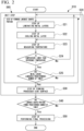
- the laminate shaping method S10 of the present embodiment mainly includes a step S20 of forming a laminate shaped portion 105, a step S30 of forming a processed side surface 103, a step S40 of determining the number of times the laminate shaped portion 105 is formed, and a step S50 of performing final processing.
- the laminate shaped portion 105 having a predetermined height H1 in the first direction D1 is formed.
- the laminate shaped portion 105 constitutes a part of a region of the shaped object 100.
- the step S20 of forming the laminate shaped portion 105 includes a step S21 of laminating the metal layer 101, a step S22 of cooling the metal layer 101, a step S23 of measuring a temperature, a step S24 of determining the temperature, and a step S25 of determining the number of laminated layers.
- the step S21 of laminating the metal layer 101, the step S22 of cooling the metal layer 101, the step S23 of measuring the temperature, the step S24 of determining the temperature, and the step S25 of determining the number of laminated layers are repeated a preset number of times.
- a predetermined number of metal layers 101 are laminated in the first direction D1 to form the laminate shaped portion 105 having the predetermined height H1.
- the laminate shaped portion 105 having the predetermined height H1 has a shaped portion side surface 106 facing a second direction D2 intersecting the first direction D1 in a cross section parallel to the axis O.
- the laminate shaped portion 105 is formed in a cylindrical shape extending in the first direction D1.
- the second direction D2 of the present embodiment is a direction orthogonal to the first direction D1 and is a radial direction (width direction) Dr of the laminate shaped portion 105. Therefore, the laminate shaped portion 105 has, as the shaped portion side surface 106, an inner shaped portion side surface 106s facing an inside Dri in the radial direction Dr (second direction D2) and an outer shaped portion side surface 106t facing an outside Dro in the radial direction Dr. That is, the inner shaped portion side surface 106s is the inner circumferential surface of the laminate shaped portion 105 facing the axis O in the radial direction Dr. In addition, the outer shaped portion side surface 106t is the outer circumferential surface of the laminate shaped portion 105 facing the side opposite to the axis O in the radial direction Dr.
- the metal layers 101 formed of the weld beads 102 formed by arc welding are laminated.
- the weld beads 102 are formed on the support surface 5f of the table 5 by arc welding.
- the weld beads 102 are formed based on shape data of the shaped object 100 input in advance.
- a plurality of passes of weld beads 102 are continuously formed by arc welding in the second direction D2 orthogonal to the first direction D1 to constitute one metal layer 101.
- the metal layer 101 is not limited to the plurality of passes of weld beads 102 constituting one layer as in the present embodiment, for example, and only one pass of the weld bead 102 may constitute one layer.
- a cooling medium is supplied to the surface of the uppermost metal layer 101 laminated in the step S21 of laminating the metal layers 101 to cool the metal layer 101.
- the uppermost metal layer 101 is the metal layer 101 located closest to the second side D1b in the first direction D1. That is, the uppermost metal layer 101 is the metal layer 101 that forms the top portion of the laminate shaped portion 105.
- the cooling medium in a liquid form is directly supplied to the surface of the uppermost metal layer 101.
- cutting oil or air is supplied as the cooling medium. Accordingly, when the step S21 of laminating the metal layers 101 is repeated, the new metal layer 101 is laminated on the surface of the uppermost metal layer 101 cooled in the step S22 of cooling the metal layer 101.
- the uppermost metal layer 101 may be subjected to processing other than cooling.
- impurities on the surface of the uppermost metal layer 101 laminated in the step S21 of laminating the metal layers 101 may be removed. Impurities are removed by scraping off impurities adhering to the surface and the periphery of the metal layer 101 with a cutting tool or a polishing tool attached to the NC processing machine as a processing tool.
- the impurities are foreign substances that are generated on and around the surface of the weld bead 102 and cause welding defects. Specifically, as the impurities, there are spatter, slag, and fume.
- the spatter is metal particles scattered around the weld bead 102.
- the slag is a foreign substance formed of an intermetallic compound generated from base metal or a welding material. Specific examples of the slag include glassy slag having a low melting point.
- the fume is a mineral dust adhering to the periphery of the weld bead 102. Fume contains components included in the base metal and welding material, but the ratio of each component is significantly different from that of the original material.
- the temperature of the surface of the uppermost metal layer 101 laminated in the step S21 of laminating the metal layers 101 is measured.
- temperature information on the surface of the metal layer 101 is acquired without touching the metal layer 101 by using a thermosensor or a non-contact thermometer. The acquired temperature information is sent to a control device (not shown) to be displayed on a monitor, or used for processing with an NC processing machine.
- the reference temperature is a temperature at which weld beads 102 can be newly formed on the metal layer 101 without causing a deterioration in welding quality, and is a temperature at which the cooling medium supplied to the surface of the metal layer 101 is regarded as evaporating. Therefore, the reference temperature is, for example, about 100°C.
- the process proceeds to the step S25 of determining the number of laminated layers.
- step S24 of determining the temperature in a case where it is determined that the temperature measured in the step S23 of measuring the temperature exceeds the reference temperature, the step S23 of measuring the temperature is performed again after a predetermined time has elapsed.
- the process determines whether or not the metal layers 101 are laminated a predetermined number of times.
- the predetermined number of times is the number of metal layers 101 required to form the laminate shaped portion 105 having the predetermined height H1, and is determined based on the shape data of the shaped object 100.
- the process returns to the step S21 of laminating the metal layers 101.
- a new metal layer 101 is formed on the metal layer 101 of which the temperature is measured.
- the process proceeds to the step S30 of forming the processed side surface 103.
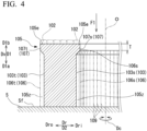
- the shaped portion side surface 106 is cut with respect to the laminate shaped portion 105 formed with the predetermined height H1. As shown in FIG. 4 , in the step S30 of forming the processed side surface 103, at least a part of the shaped portion side surface 106 is cut in the laminate shaped portion 105 to form the processed side surface 103.
- the processed side surface 103 is formed by cutting the shaped portion side surface 106 by a predetermined dimension so as to be recessed in the radial direction Dr.
- the processed side surface 103 is formed as a smooth surface having a surface roughness smaller than that of the shaped portion side surface 106.
- the processed side surface 103 is formed by removing an excess thickness portion 105z of the laminate shaped portion 105.
- the excess thickness portion 105z is a portion formed in a region larger than the shape of the shaped object 100 in the laminate shaped portion 105, and is a portion including sagging generated during welding.
- the processed side surface 103 of the present embodiment constitutes a side surface as a product. That is, the processed side surface 103 is a part of the inner circumferential surface and the outer circumferential surface of the shaped object 100 in the cross section parallel to the axis O.
- an inner processed side surface 103s is formed on the inner shaped portion side surface 106s facing the inside Dri in the radial direction Dr.
- an outer processed side surface 103t is further formed on the outer shaped portion side surface 106t facing the outside Dro in the radial direction Dr.
- the processed side surface 103 is formed so that a receiving portion 107 projecting in the second direction D2 with respect to the processed side surface 103 is left at an end portion 105e on the second side D1b of the uppermost layer of the laminate shaped portion 105 in the first direction D1.
- the end portion 105e is a corner portion of the uppermost layer of the laminate shaped portion 105.
- the receiving portion 107 includes an inner receiving portion 107s projecting from the inner processed side surface 103s toward the inside Dri in the radial direction Dr, and an outer receiving portion 107t projecting from the outer processed side surface 103t toward the outside Dro in the radial direction Dr.
- a thickness T of the receiving portion 107 in the first direction D1 is preferably equal to or larger than the penetration dimension of the weld beads 102 with respect to the receiving portion 107.
- the thickness T of the receiving portion 107 is preferably, for example, twice or more and five times or less with respect to the penetration dimension of the weld beads 102.
- the penetration dimension is the length in the first direction D1 of the portion that melts when the weld bead is formed.
- the receiving portion 107 of the present embodiment is formed to leave the shaped portion side surface 106 at least partially in the first direction D1.
- the receiving portion 107 may be formed without leaving the shaped portion side surface 106.
- the inner receiving portion 107s is formed so that the thickness T gradually decreases from the outside Dro toward the inside Dri in the radial direction Dr.
- the outer receiving portion 107t is formed so that the thickness T gradually decreases from the inside Dri toward the outside Dro in the radial direction Dr.
- the thickness T of the inner receiving portion 107s and the outer receiving portion 107t in the radial direction Dr may be constant. It is preferable that the cross-sectional shapes of the inner receiving portion 107s and the outer receiving portion 107t parallel to the axis O may be shapes close to line symmetry.
- the shaped portion side surface 106 is cut while the tool is moved in the first direction D1 by the NC processing machine when the processed side surface 103 is formed. That is, the processed side surface 103 is formed by cutting the shaped portion side surface 106 in the flow direction F1. Accordingly, a plurality of processing marks 109 extending in the first direction D1 are formed on the processed side surface 103 in a circumferential direction Dc centered on the axis O. Accordingly, the processing marks 109 are in a state of extending along the flow direction F1 of the fluid flowing through the inside of the shaped object 100 after completion.
- the shape (dimensions) of the formed processed side surface 103 may be measured.
- the shape of the processed side surface 103 is measured by contact or in a non-contact manner using, for example, a three-dimensional measuring device. Specifically, in a case of measuring the shape of the processed side surface 103 in a non-contact manner, for example, a laser beam, a pattern light, or an arc sensor is used. In a case of measuring the shape of the processed side surface 103 by contact, for example, a touch sensor is used. After measuring the shape of the processed side surface 103, it is determined whether or not the measured shape of the processed side surface 103 deviates from a predetermined reference.
- the predetermined reference is determined according to the dimensions that can be tolerated for the shape of the final shaped object 100.
- Examples of the reference include a value considering a certain dimensional tolerance in the shape data of the shaped object 100.
- additional processing may be performed until the shape does not deviate from the reference.
- the unit step S60 is a step including the step S20 of forming the laminate shaped portion 105 and the step S30 of forming the processed side surface 103.
- the unit step S60 is repeatedly performed.
- the process proceeds to step S40 of determining the number of times the laminate shaped portion 105 is formed.
- the predetermined number of times is the number of laminate shaped portions 105 required to form the shaped object 100, and is determined based on the shape data of the shaped object 100.
- the unit step S60 is repeated.
- the process proceeds to step S50 of performing final processing.
- the process returns to the step S21 of laminating the metal layers 101.
- the step S20 of forming the laminate shaped portion 105 a new metal layer 101 is laminated so as to overlap the upper surface (the surface of the uppermost layer) of the receiving portion 107 in the first direction D1.
- the metal layer 101 newly formed when the laminate shaped portion 105 is additionally formed is formed so as to overlap the receiving portion 107 with respect to the surface of the uppermost metal layer 101 of the laminate shaped portion 105 that has already been formed.
- the receiving portion 107 projects in the second direction D2 with respect to the processed side surface 103.
- the excess thickness portion 105z of the additionally formed laminate shaped portion 105 is formed on the receiving portion 107.
- the heat energy due to the penetration of the weld beads 102 in a portion forming the excess thickness portion 105z and the heat of the weld beads 102 themselves is absorbed by the receiving portion 107.
- the shaped portion side surface 106 is cut with respect to the newly formed laminate shaped portion 105.
- the processed side surface 103 is formed on the end portion 105e of the newly formed laminate shaped portion 105 so that the receiving portion 107 projecting in the second direction D2 is newly left. Furthermore, the receiving portion 107 of the laminate shaped portion 105 that has already been formed is cut.
- the processed side surface 103 (the inner processed side surface 103s and the outer processed side surface 103t) of the laminate shaped portion 105 that has already been formed and the processed side surface 103 (the inner processed side surface 103s and the outer processed side surface 103t) of the newly formed laminate shaped portion 105 are formed as a smooth surface that is continuous in the first direction D1.
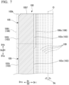
- the shaped portion side surface 106 (the inner shaped portion side surface 106s and the outer shaped portion side surface 106t) of the laminate shaped portion 105 that is formed finally and is located closest to the second side D1b in the first direction D1 is cut to form the processed side surface 103 (the inner processed side surface 103s and the outer processed side surface 103t).
- the processed side surface 103 of the laminate shaped portion 105 that has already been formed and the processed side surface 103 of the laminate shaped portion 105 that is finally formed form a continuous smooth surface in the first direction D1.
- the surface (the upper surface of the shaped object 100) of the laminate shaped portion 105 located closest to the second side D1b in the first direction D1 may be cut to form a flat surface 105f orthogonal to the first direction D1.
- the corner portion of the shaped object 100 may be subjected to processing such as forming a beveled portion 105k for welding the shaped object 100 to another component.
- finishing may be performed on the outer processed side surface 103t with a predetermined processing accuracy so as to further reduce the surface roughness of the outer processed side surface 103t facing the outside Dro in the radial direction Dr of the plurality of laminate shaped portions 105 that are laminated.
- the shaping of the shaped object 100 having the predetermined dimensions is completed.
- the processed side surface 103 is formed so that the receiving portion 107 is left at the uppermost layer of the laminate shaped portion 105.
- the receiving portion 107 projects in the second direction D2 with respect to the processed side surface 103.
- the new metal layer 101 is laminated on the receiving portion 107, so that the heat energy due to the penetration of the weld beads 102 and the thermal effect of the weld beads 102 can be absorbed by the receiving portion 107 during the lamination of the weld beads 102.
- the receiving portion 107 can suppress collapse of the shape of the processed side surface 103 due to adhesion of sagging of molten metal to the processed side surface 103. As a result, it is possible to suppress the influence of sagging of the metal during the lamination of the metal and form a three-dimensional shaped object 100 with good quality.
- the metal layers 101 are laminated in the first direction D1 to form the laminate shaped portion 105.
- the processed side surface 103 is formed by cutting the shaped portion side surface 106 for each of the formed laminate shaped portions 105.
- the laminate shaped portions 105 are sequentially laminated in the first direction D1 by repeatedly performing the unit step S60.
- the processed side surface 103 is formed for each of the formed laminate shaped portions 105.
- the shaped portion side surface 106 of the laminate shaped portion 105 is cut for each unit step S60, it does not become difficult for the tool to access the shaped portion side surface 106. As a result, all the side surfaces of the shaped object 100, which is the final finished product, can be formed into the processed side surface 103 having the intended shape.
- the thickness T of the receiving portion 107 in the first direction D1 By causing the thickness T of the receiving portion 107 in the first direction D1 to be equal to or larger than the penetration dimension of the weld beads 102 with respect to the receiving portion 107, the heat energy due to the penetration of the weld beads 102 and the heat of the weld beads 102 themselves can be sufficiently absorbed by the receiving portion 107. As a result, it is possible to stably suppress the adhesion of the metal sagging during the formation of the metal layer 101 to the processed side surface 103. Therefore, the processed side surface 103 that has already been formed can be maintained in the intended shape, and the three-dimensional shaped object 100 can be formed with better quality.
- the receiving portion 107 by forming the receiving portion 107 with the shaped portion side surface 106 left, it is possible to secure a certain thickness in the receiving portion 107 from the root to the tip end portion of the receiving portion 107 in the second direction D2. As a result, the weld beads 102 forming the new metal layer 101 can be stably received by the receiving portion 107. Accordingly, it is possible to more effectively suppress the occurrence of metal sagging during the lamination of the metal.
- the inner processed side surface 103s is formed on the inner shaped portion side surface 106s of the laminate shaped portion 105 for each unit step S60. Accordingly, even in the shaped object 100 having a cylindrical shape, it is possible to satisfactorily process the inner circumferential surface of the shaped object 100 while suppressing an obstacle to access of tools or the like.
- the outer processed side surface 103t is formed on the outer shaped portion side surface 106t facing the outside Dro in the radial direction Dr of the shaped object 100. Accordingly, it is possible to satisfactorily process the outer circumferential surface of the shaped object 100 having a cylindrical shape together with the inner processed side surface 103s.
- the surface of the uppermost metal layer 101 is cooled. By the cooling, the temperature of the uppermost metal layer 101 is lowered. In a case where the metal layers 101 are laminated, there is a possibility that lamination of the new metal layer 101 on the metal layer 101 in a state where the temperature is too high may cause deterioration of the welding quality. However, by cooling the uppermost metal layer 101, it is possible to prevent the new metal layer 101 from being laminated on the metal layer 101 in a high temperature state. Furthermore, compared to a case where the metal layer 101 is simply left to cool, the welding waiting time until the start of the formation of a new metal layer 101 can be shortened.
- the shaped portion side surface 106 is cut along the flow direction of the fluid flowing through the shaped object 100. Accordingly, the processing marks 109 formed on the processed side surface 103 are formed along the flow direction F1 of the fluid flowing through the shaped object 100.
- the processing marks 109 make it difficult for turbulence such as a vortex to occur. Accordingly, the influence of the processing marks 109 on the flow of the fluid can be suppressed. Therefore, even if the surface state of the processing marks 109 is slightly rough, it is difficult for a loss to occur in the flow of the fluid. Accordingly, it is possible to perform the processing for forming the processed side surface 103 more easily and in a short period of time.
- the receiving portions 107 are formed on the shaped portion side surfaces 106 at both end portions in the second direction D2, but are not limited to this configuration.
- the receiving portion 107 may be formed only on the shaped portion side surface 106 on either one side of the second directions D2.
- the receiving portions 107 are not limited to the structure in which the receiving portions 107 are formed in the same shape as in the present embodiment, but the shape and size of the receiving portions 107 may be changed depending on the formation position.
- shaped object 100 a cylindrical shape is formed, but the shaped object 100 is not limited thereto.
- the shape and configuration of the shaped object 100 may employ, for example, another configuration as appropriate, such as a wall shape.
- the outer processed side surface 103t is formed on the laminate shaped portion 105 having the predetermined height H1 for each unit step S60, but the outer processed side surface 103t is not limited thereto. Even if the shaped object 100 has a cylindrical shape, there is no problem in processing of the outer processed side surface 103t because the processing is performed from the outside Dro in the radial direction Dr. In such a case, the outer processed side surface 103t may not be formed whenever the laminate shaped portion 105 having the predetermined height H1 is formed (for each unit step S60), but the outer processed side surfaces 103t may be collectively formed in the step S50 of performing the final processing.
- the number of times the outer processed side surface 103t is formed may be smaller than the number of times the inner processed side surface 103s is formed.
- the order of the laminate shaping method S10 is not limited to the above description, and changes such as changing the order, omitting some steps, and adding other steps may be performed. For example, it is not necessary to perform the step S22 of cooling the metal layer 101, the step S23 of measuring the temperature, and the step S24 of determining the temperature.
- the step S20 of forming the laminate shaped portion 105 is not limited to forming a plurality of the metal layers 101. That is, in the step S21 of laminating the metal layers 101, only one metal layer 101 may be formed, and the step S30 of forming the processed side surface 103 may be performed.
- Examples of the shaped object 100 include a component forming a rotating machine such as a turbine or a compressor. Specific examples include a nozzle, an impeller, and a casing.
- the new metal layer 101 is laminated on the receiving portion 107, so that the heat energy due to the penetration of the weld beads 102 and the thermal effect of the weld beads 102 can be absorbed by the receiving portion 107 during the lamination of the weld beads 102. Accordingly, the receiving portion 107 can suppress collapse of the shape of the processed side surface 103 due to adhesion of sagging of molten metal to the processed side surface 103. As a result, it is possible to suppress the influence of sagging of the metal during the lamination of the metal and form a three-dimensional shaped object 100 with good quality.
- a laminate shaping method S10 according to a second aspect is the laminate shaping method S10 of (1), in which the thickness T of the receiving portion 107 in the first direction D1 is equal to or larger than the penetration dimension of the weld beads 102 into the receiving portion 107.
- the heat energy due to the penetration of the weld beads 102 and the heat of the weld beads 102 themselves can be sufficiently absorbed by the receiving portion 107.
- a laminate shaping method S10 according to a third aspect is the laminate shaping method S10 of (1) or (2), in which the receiving portion 107 is formed to leave the shaped portion side surface 106 at least partially in the first direction D1.
- the weld beads 102 forming the new metal layer 101 can be stably received by the receiving portion 107. Accordingly, it is possible to more effectively suppress the occurrence of metal sagging during the lamination of the metal.
- a laminate shaping method S10 according to a fourth aspect is the laminate shaping method S10 according to any one of (1) to (3), in which, in the step S20 of forming the laminate shaped portion 105, after cooling the metal layer 101 by supplying a cooling medium to the surface of the metal layer 101 forming the uppermost layer in the first direction D1, the new metal layer 101 is laminated on the surface of the metal layer 101 after cooling.
- the surface of the uppermost metal layer 101 is cooled by the cooling medium and the temperature is lowered. Therefore, it is possible to prevent the new metal layer 101 from being laminated on the metal layer 101 in a high temperature state. Furthermore, compared to a case where the metal layer 101 is simply left to cool, the welding waiting time until the start of the formation of a new metal layer 101 can be shortened.
- a laminate shaping method S10 according to a fifth aspect is the laminate shaping method S10 according to any one of (1) to (4), in which the shaped object 100 is formed in a cylindrical shape centered on the axis O extending in the first direction D1 so as to allow the fluid to flow through an inside of the shaped object 100, in the step of forming the processed side surface 103, a side surface of the shaped object 100 facing toward the inside Dri in the radial direction Dr is formed by the processed side surface 103, and the processed side surface 103 is formed by cutting the shaped portion side surface 106 in the flow direction of the fluid flowing through the inside of the shaped object 100.
- the shaped portion side surface 106 is cut along the flow direction of the fluid flowing through the shaped object 100.
- the processing marks 109 formed on the processed side surface 103 are formed along the flow direction F1 of the fluid flowing through the shaped object 100.
- the processing marks 109 make it difficult for turbulence such as a vortex to occur. Accordingly, the influence of the processing marks 109 on the flow of the fluid can be suppressed. Therefore, even if the surface state of the processing marks 109 is slightly rough, it is difficult for a loss to occur in the flow of the fluid. Accordingly, it is possible to perform the processing for forming the processed side surface 103 more easily and in a short period of time.
- the laminate shaping method of the present disclosure it is possible to form a three-dimensional shaped object with good quality by suppressing the influence of sagging when metal layers are laminated by welding.
Landscapes
- Engineering & Computer Science (AREA)
- Mechanical Engineering (AREA)
- Physics & Mathematics (AREA)
- Plasma & Fusion (AREA)
- Chemical & Material Sciences (AREA)
- Manufacturing & Machinery (AREA)
- Materials Engineering (AREA)
- Arc Welding In General (AREA)
- Butt Welding And Welding Of Specific Article (AREA)
- Laminated Bodies (AREA)
Abstract
Description
- The present disclosure relates to a laminate shaping method.
- For example,
Japanese Unexamined Patent Application, First Publication No. 2019-84553 - [Patent Document 1]
Japanese Unexamined Patent Application, First Publication No. 2019-84553 - However, in the configuration as disclosed in
Japanese Unexamined Patent Application, First Publication No. 2019-84553 - The present disclosure provides a laminate shaping method in which a three-dimensional shaped object can be formed with good quality by suppressing the influence of sagging when metal layers are laminated by welding.
- A laminate shaping method according to the present disclosure is a laminate shaping method of shaping a three-dimensional shaped object formed by sequentially laminating a plurality of metal layers, the method including: a unit step repeatedly performed, the unit step including a step of forming a laminate shaped portion by laminating metal layers formed of weld beads, and a step of forming a processed side surface by cutting a shaped portion side surface of the laminate shaped portion that faces a second direction intersecting a first direction in which the metal layers are laminated, in which, in the step of forming the processed side surface, the shaped portion side surface is cut so that a receiving portion projecting in the second direction with respect to the processed side surface, the receiving portion is formed at an uppermost layer of the laminate shaped portion in the first direction, and when the unit step is repeated, in the step of forming the laminate shaped portion, a new metal layer is laminated so as to overlap an upper surface of the receiving portion in the first direction.
- According to the laminate shaping method of the present disclosure, it is possible to form a three-dimensional shaped object with good quality by suppressing the influence of sagging when metal layers are laminated by welding.
-
-
FIG. 1 is a cross-sectional view parallel to an axis showing an example of a shaped object shaped in a laminate shaping method according to the embodiment of the present disclosure. -
FIG. 2 is a flowchart showing the order of the laminate shaping method. -
FIG. 3 is a semi-cross-sectional view parallel to the axis showing a state in which a laminate shaped portion having a predetermined height is formed in a step of forming a laminate shaped portion of the laminate shaping method. -
FIG. 4 is a semi-cross-sectional view parallel to the axis showing a state in which a receiving portion and a processed side surface are formed in the laminate shaped portion in a step of forming a processed side surface of the laminate shaping method. -
FIG. 5 is a semi-cross-sectional view parallel to the axis showing a state in which a new laminate shaped portion is formed by laminating a metal layer on the receiving portion in a step of forming a laminate shaped portion in second and subsequent unit steps in the laminate shaping method. -
FIG. 6 is a semi-cross-sectional view parallel to the axis showing a state in which a receiving portion and a processed side surface are formed in the new laminate shaped portion in the step of forming a laminate shaped portion in the second and subsequent unit steps in the laminate shaping method. -
FIG. 7 is a semi-cross-sectional view parallel to the axis showing a state in which a shaped product is formed in a step of performing final processing of the laminate shaping method. - Hereinafter, an embodiment for carrying out a laminate shaping method according to the present disclosure will be described with reference to the accompanying drawings. However, the present disclosure is not limited to this embodiment.
- As shown in
FIG. 1 , in a laminate shaping method S10 in the embodiment of the present disclosure, a three-dimensionalshaped object 100 is shaped. Theshaped object 100 shaped in the laminate shaping method S10 of the present embodiment is a component forming a rotating machine such as a turbine or a compressor. More specifically, as theshaped object 100 to be shaped, there are a nozzle, an impeller, and a casing. In the present embodiment, as theshaped object 100, a cylindrical nozzle extending in a first direction D1 centered on an axis O is shaped. A fluid which is a gas such as steam or air can flow through the inside of the nozzle (the shaped object 100) after completion as a working fluid so that the first direction D1 is a flow direction F1 (seeFIG. 4 ). - In the laminate shaping method S10, a plurality of
metal layers 101 are laminated on asupport surface 5f of a table 5, and theshaped object 100 having a predetermined shape is shaped. The laminate shaping method S10 is carried out by a numerical control (NC) processing machine to which a welding torch and a processing tool are attached. Onemetal layer 101 consists ofweld beads 102. Theweld beads 102 are generated by arc welding performed by the welding torch of the NC processing machine. Thesupport surface 5f of the table 5 forms a surface orthogonal to the first direction D1. In the present embodiment, the first direction D1 is set to coincide with a vertical direction Dv. Accordingly, the plurality ofmetal layers 101 are laminated on thesupport surface 5f from a first side D1a (a side approaching thesupport surface 5f with respect to the metal layer 101) toward a second side D1b (a side away from thesupport surface 5f with respect to the metal layer 101) in the first direction D1. That is, the first direction D1 is the direction in which themetal layers 101 are laminated. The first direction D1 may be a direction inclined with respect to the vertical direction Dv as long as the first direction D1 is not orthogonal to the vertical direction Dv. - As shown in
FIG. 2 , the laminate shaping method S10 of the present embodiment mainly includes a step S20 of forming a laminate shapedportion 105, a step S30 of forming a processedside surface 103, a step S40 of determining the number of times the laminate shapedportion 105 is formed, and a step S50 of performing final processing. - As shown in
FIG. 3 , in the step S20 of forming the laminateshaped portion 105, the laminateshaped portion 105 having a predetermined height H1 in the first direction D1 is formed. The laminateshaped portion 105 constitutes a part of a region of theshaped object 100. As shown inFIG. 2 , the step S20 of forming the laminateshaped portion 105 includes a step S21 of laminating themetal layer 101, a step S22 of cooling themetal layer 101, a step S23 of measuring a temperature, a step S24 of determining the temperature, and a step S25 of determining the number of laminated layers. In the step S20 of forming the laminateshaped portion 105, the step S21 of laminating themetal layer 101, the step S22 of cooling themetal layer 101, the step S23 of measuring the temperature, the step S24 of determining the temperature, and the step S25 of determining the number of laminated layers are repeated a preset number of times. In the step S20 of forming the laminate shapedportion 105, a predetermined number ofmetal layers 101 are laminated in the first direction D1 to form the laminateshaped portion 105 having the predetermined height H1. The laminateshaped portion 105 having the predetermined height H1 has a shapedportion side surface 106 facing a second direction D2 intersecting the first direction D1 in a cross section parallel to the axis O. In the present embodiment, the laminateshaped portion 105 is formed in a cylindrical shape extending in the first direction D1. In addition, the second direction D2 of the present embodiment is a direction orthogonal to the first direction D1 and is a radial direction (width direction) Dr of the laminate shapedportion 105. Therefore, the laminateshaped portion 105 has, as the shapedportion side surface 106, an inner shapedportion side surface 106s facing an inside Dri in the radial direction Dr (second direction D2) and an outer shapedportion side surface 106t facing an outside Dro in the radial direction Dr. That is, the inner shapedportion side surface 106s is the inner circumferential surface of the laminateshaped portion 105 facing the axis O in the radial direction Dr. In addition, the outer shapedportion side surface 106t is the outer circumferential surface of the laminate shapedportion 105 facing the side opposite to the axis O in the radial direction Dr. - As shown in
FIG. 3 , in the step S21 of laminating themetal layers 101, themetal layers 101 formed of theweld beads 102 formed by arc welding are laminated. In the step S21 of laminating themetal layers 101, first, theweld beads 102 are formed on thesupport surface 5f of the table 5 by arc welding. In the step S21 of laminating themetal layers 101, theweld beads 102 are formed based on shape data of theshaped object 100 input in advance. In the step S21 of laminating themetal layers 101 of the present embodiment, a plurality of passes ofweld beads 102 are continuously formed by arc welding in the second direction D2 orthogonal to the first direction D1 to constitute onemetal layer 101. In the step S21 of laminating themetal layers 101, it is preferable to form theweld beads 102 by high-speed welding such as rotary arc welding. - The
metal layer 101 is not limited to the plurality of passes ofweld beads 102 constituting one layer as in the present embodiment, for example, and only one pass of theweld bead 102 may constitute one layer. - In the step S22 of cooling the
metal layer 101, a cooling medium is supplied to the surface of theuppermost metal layer 101 laminated in the step S21 of laminating themetal layers 101 to cool themetal layer 101. Theuppermost metal layer 101 is themetal layer 101 located closest to the second side D1b in the first direction D1. That is, theuppermost metal layer 101 is themetal layer 101 that forms the top portion of the laminateshaped portion 105. In the step S22 of cooling themetal layer 101 of the present embodiment, the cooling medium in a liquid form is directly supplied to the surface of theuppermost metal layer 101. In the step S22 of cooling themetal layer 101, for example, cutting oil or air is supplied as the cooling medium. Accordingly, when the step S21 of laminating themetal layers 101 is repeated, thenew metal layer 101 is laminated on the surface of theuppermost metal layer 101 cooled in the step S22 of cooling themetal layer 101. - In the step S22 of cooling the
metal layer 101 of the present embodiment, for example, theuppermost metal layer 101 may be subjected to processing other than cooling. For example, in the step S22 of cooling themetal layer 101, impurities on the surface of theuppermost metal layer 101 laminated in the step S21 of laminating themetal layers 101 may be removed. Impurities are removed by scraping off impurities adhering to the surface and the periphery of themetal layer 101 with a cutting tool or a polishing tool attached to the NC processing machine as a processing tool. Here, the impurities are foreign substances that are generated on and around the surface of theweld bead 102 and cause welding defects. Specifically, as the impurities, there are spatter, slag, and fume. The spatter is metal particles scattered around theweld bead 102. The slag is a foreign substance formed of an intermetallic compound generated from base metal or a welding material. Specific examples of the slag include glassy slag having a low melting point. The fume is a mineral dust adhering to the periphery of theweld bead 102. Fume contains components included in the base metal and welding material, but the ratio of each component is significantly different from that of the original material. - In the step S23 of measuring the temperature, the temperature of the surface of the
uppermost metal layer 101 laminated in the step S21 of laminating the metal layers 101 is measured. In the step S23 of measuring the temperature, temperature information on the surface of themetal layer 101 is acquired without touching themetal layer 101 by using a thermosensor or a non-contact thermometer. The acquired temperature information is sent to a control device (not shown) to be displayed on a monitor, or used for processing with an NC processing machine. - In the step S24 of determining the temperature, it is determined whether or not the measured temperature of the surface of the
metal layer 101 is lower than a predetermined reference temperature. Here, the reference temperature is a temperature at whichweld beads 102 can be newly formed on themetal layer 101 without causing a deterioration in welding quality, and is a temperature at which the cooling medium supplied to the surface of themetal layer 101 is regarded as evaporating. Therefore, the reference temperature is, for example, about 100°C. In the step S24 of determining the temperature, in a case where it is determined that the measured temperature is lower than the reference temperature, the process proceeds to the step S25 of determining the number of laminated layers. In addition, in the step S24 of determining the temperature, in a case where it is determined that the temperature measured in the step S23 of measuring the temperature exceeds the reference temperature, the step S23 of measuring the temperature is performed again after a predetermined time has elapsed. - In the step S25 of determining the number of laminated layers, it is determined whether or not the metal layers 101 are laminated a predetermined number of times. Here, the predetermined number of times is the number of
metal layers 101 required to form the laminate shapedportion 105 having the predetermined height H1, and is determined based on the shape data of the shapedobject 100. In the step S25 of determining the number of laminated layers, in a case where it is determined that the metal layers 101 are not laminated a predetermined number of times, the process returns to the step S21 of laminating the metal layers 101. In the step S21 of laminating the metal layers 101 after the step S25 of determining the number of laminated layers, anew metal layer 101 is formed on themetal layer 101 of which the temperature is measured. In the step S25 of determining the number of laminated layers, in a case where it is determined that the metal layers 101 are laminated a predetermined number of times, the process proceeds to the step S30 of forming the processedside surface 103. - In the step S30 of forming the processed
side surface 103, the shapedportion side surface 106 is cut with respect to the laminate shapedportion 105 formed with the predetermined height H1. As shown inFIG. 4 , in the step S30 of forming the processedside surface 103, at least a part of the shapedportion side surface 106 is cut in the laminate shapedportion 105 to form the processedside surface 103. - The processed
side surface 103 is formed by cutting the shapedportion side surface 106 by a predetermined dimension so as to be recessed in the radial direction Dr. The processedside surface 103 is formed as a smooth surface having a surface roughness smaller than that of the shapedportion side surface 106. The processedside surface 103 is formed by removing anexcess thickness portion 105z of the laminate shapedportion 105. Theexcess thickness portion 105z is a portion formed in a region larger than the shape of the shapedobject 100 in the laminate shapedportion 105, and is a portion including sagging generated during welding. In addition, the processedside surface 103 of the present embodiment constitutes a side surface as a product. That is, the processedside surface 103 is a part of the inner circumferential surface and the outer circumferential surface of the shapedobject 100 in the cross section parallel to the axis O. - In the present embodiment, in the laminate shaped
portion 105, an inner processedside surface 103s is formed on the inner shapedportion side surface 106s facing the inside Dri in the radial direction Dr. In addition, in the present embodiment, an outer processedside surface 103t is further formed on the outer shapedportion side surface 106t facing the outside Dro in the radial direction Dr. - In the step S30 of forming the processed
side surface 103, the processedside surface 103 is formed so that a receivingportion 107 projecting in the second direction D2 with respect to the processedside surface 103 is left at anend portion 105e on the second side D1b of the uppermost layer of the laminate shapedportion 105 in the first direction D1. Theend portion 105e is a corner portion of the uppermost layer of the laminate shapedportion 105. In the present embodiment, the receivingportion 107 includes aninner receiving portion 107s projecting from the inner processedside surface 103s toward the inside Dri in the radial direction Dr, and anouter receiving portion 107t projecting from the outer processedside surface 103t toward the outside Dro in the radial direction Dr. - A thickness T of the receiving
portion 107 in the first direction D1 is preferably equal to or larger than the penetration dimension of theweld beads 102 with respect to the receivingportion 107. The thickness T of the receivingportion 107 is preferably, for example, twice or more and five times or less with respect to the penetration dimension of theweld beads 102. The penetration dimension is the length in the first direction D1 of the portion that melts when the weld bead is formed. The receivingportion 107 of the present embodiment is formed to leave the shapedportion side surface 106 at least partially in the first direction D1. The receivingportion 107 may be formed without leaving the shapedportion side surface 106. - The
inner receiving portion 107s is formed so that the thickness T gradually decreases from the outside Dro toward the inside Dri in the radial direction Dr. Theouter receiving portion 107t is formed so that the thickness T gradually decreases from the inside Dri toward the outside Dro in the radial direction Dr. The thickness T of theinner receiving portion 107s and the outer receivingportion 107t in the radial direction Dr may be constant. It is preferable that the cross-sectional shapes of theinner receiving portion 107s and the outer receivingportion 107t parallel to the axis O may be shapes close to line symmetry. - In the step S30 of forming the processed
side surface 103, it is preferable that the shapedportion side surface 106 is cut while the tool is moved in the first direction D1 by the NC processing machine when the processedside surface 103 is formed. That is, the processedside surface 103 is formed by cutting the shapedportion side surface 106 in the flow direction F1. Accordingly, a plurality of processing marks 109 extending in the first direction D1 are formed on the processedside surface 103 in a circumferential direction Dc centered on the axis O. Accordingly, the processing marks 109 are in a state of extending along the flow direction F1 of the fluid flowing through the inside of the shapedobject 100 after completion. - Here, after the step S30 of forming the processed
side surface 103 is completed, the shape (dimensions) of the formed processedside surface 103 may be measured. The shape of the processedside surface 103 is measured by contact or in a non-contact manner using, for example, a three-dimensional measuring device. Specifically, in a case of measuring the shape of the processedside surface 103 in a non-contact manner, for example, a laser beam, a pattern light, or an arc sensor is used. In a case of measuring the shape of the processedside surface 103 by contact, for example, a touch sensor is used. After measuring the shape of the processedside surface 103, it is determined whether or not the measured shape of the processedside surface 103 deviates from a predetermined reference. Here, the predetermined reference is determined according to the dimensions that can be tolerated for the shape of the final shapedobject 100. Examples of the reference include a value considering a certain dimensional tolerance in the shape data of the shapedobject 100. In a case where it is determined that the shape of the processedside surface 103 deviates from the reference, additional processing may be performed until the shape does not deviate from the reference. - In this manner, in the step S30 of forming the processed
side surface 103, the inner processedside surface 103s and the outer processedside surface 103t are formed, so that one unit step S60 is completed. As shown inFIG. 2 , the unit step S60 is a step including the step S20 of forming the laminate shapedportion 105 and the step S30 of forming the processedside surface 103. In the laminate shaping method S10, the unit step S60 is repeatedly performed. When one unit step S60 is completed, the process proceeds to step S40 of determining the number of times the laminate shapedportion 105 is formed. - In the step S40 of determining the number of times the laminate shaped
portion 105 is formed, it is determined whether or not the laminate shapedportion 105 is formed a predetermined number of times. Here, the predetermined number of times is the number of laminate shapedportions 105 required to form the shapedobject 100, and is determined based on the shape data of the shapedobject 100. In the step S40 of determining the number of times the laminate shapedportion 105 is formed, in a case where it is determined that the laminate shapedportion 105 is not formed the predetermined number of times, the unit step S60 is repeated. In the step S40 of determining the number of times the laminate shapedportion 105 is formed, in a case where it is determined that the laminate shapedportion 105 is formed the predetermined number of times, the process proceeds to step S50 of performing final processing. - In a case where the unit step S60 is repeated, the process returns to the step S21 of laminating the metal layers 101. As shown in
FIG. 5 , when the unit step S60 is repeated (when the second and subsequent unit steps S60 are performed), in the step S20 of forming the laminate shapedportion 105, anew metal layer 101 is laminated so as to overlap the upper surface (the surface of the uppermost layer) of the receivingportion 107 in the first direction D1. Specifically, themetal layer 101 newly formed when the laminate shapedportion 105 is additionally formed is formed so as to overlap the receivingportion 107 with respect to the surface of theuppermost metal layer 101 of the laminate shapedportion 105 that has already been formed. The receivingportion 107 projects in the second direction D2 with respect to the processedside surface 103. Therefore, by sequentially laminating the metal layers 101 of the newly additionally formed laminate shapedportion 105, theexcess thickness portion 105z of the additionally formed laminate shapedportion 105 is formed on the receivingportion 107. When thenew metal layer 101 is laminated on the upper surface of the receivingportion 107, the heat energy due to the penetration of theweld beads 102 in a portion forming theexcess thickness portion 105z and the heat of theweld beads 102 themselves is absorbed by the receivingportion 107. - In addition, in the step S30 of forming the processed
side surface 103 in the second and subsequent unit steps S60, the shapedportion side surface 106 is cut with respect to the newly formed laminate shapedportion 105. In this case, as shown inFIG. 6 , the processedside surface 103 is formed on theend portion 105e of the newly formed laminate shapedportion 105 so that the receivingportion 107 projecting in the second direction D2 is newly left. Furthermore, the receivingportion 107 of the laminate shapedportion 105 that has already been formed is cut. Accordingly, the processed side surface 103 (the inner processedside surface 103s and the outer processedside surface 103t) of the laminate shapedportion 105 that has already been formed and the processed side surface 103 (the inner processedside surface 103s and the outer processedside surface 103t) of the newly formed laminate shapedportion 105 are formed as a smooth surface that is continuous in the first direction D1. - In the step S50 of performing the final processing performed after the laminate shaped
portion 105 is laminated the predetermined number of times, as shown inFIG. 7 , the shaped portion side surface 106 (the inner shapedportion side surface 106s and the outer shapedportion side surface 106t) of the laminate shapedportion 105 that is formed finally and is located closest to the second side D1b in the first direction D1 is cut to form the processed side surface 103 (the inner processedside surface 103s and the outer processedside surface 103t). In this case, it is not necessary to form the receivingportion 107 in the finally formed laminate shapedportion 105. Accordingly, the processedside surface 103 of the laminate shapedportion 105 that has already been formed and the processedside surface 103 of the laminate shapedportion 105 that is finally formed form a continuous smooth surface in the first direction D1. - In the step S50 of performing the final processing, the surface (the upper surface of the shaped object 100) of the laminate shaped
portion 105 located closest to the second side D1b in the first direction D1 may be cut to form aflat surface 105f orthogonal to the first direction D1. In addition, in the step S50 of performing the final processing, the corner portion of the shapedobject 100 may be subjected to processing such as forming abeveled portion 105k for welding the shapedobject 100 to another component. Furthermore, in the step S50 of performing the final processing, finishing may be performed on the outer processedside surface 103t with a predetermined processing accuracy so as to further reduce the surface roughness of the outer processedside surface 103t facing the outside Dro in the radial direction Dr of the plurality of laminate shapedportions 105 that are laminated. When the step S50 of performing the final processing is completed, the shaping of the shapedobject 100 having the predetermined dimensions is completed. - In the laminate shaping method S10 having the above configuration, in the step S30 of forming the processed
side surface 103, the processedside surface 103 is formed so that the receivingportion 107 is left at the uppermost layer of the laminate shapedportion 105. The receivingportion 107 projects in the second direction D2 with respect to the processedside surface 103. When the unit step S60 is repeated, thenew metal layer 101 is laminated on the receivingportion 107, so that the heat energy due to the penetration of theweld beads 102 and the thermal effect of theweld beads 102 can be absorbed by the receivingportion 107 during the lamination of theweld beads 102. Accordingly, the receivingportion 107 can suppress collapse of the shape of the processedside surface 103 due to adhesion of sagging of molten metal to the processedside surface 103. As a result, it is possible to suppress the influence of sagging of the metal during the lamination of the metal and form a three-dimensionalshaped object 100 with good quality. - The metal layers 101 are laminated in the first direction D1 to form the laminate shaped
portion 105. The processedside surface 103 is formed by cutting the shapedportion side surface 106 for each of the formed laminate shapedportions 105. The laminate shapedportions 105 are sequentially laminated in the first direction D1 by repeatedly performing the unit step S60. Here, in a state where a plurality of the laminate shapedportions 105 are laminated in the first direction D1 and are close to the shape of the final shapedobject 100, it may be difficult for the tool for processing to access the shapedportion side surface 106. However, in the present embodiment, the processedside surface 103 is formed for each of the formed laminate shapedportions 105. That is, since the shapedportion side surface 106 of the laminate shapedportion 105 is cut for each unit step S60, it does not become difficult for the tool to access the shapedportion side surface 106. As a result, all the side surfaces of the shapedobject 100, which is the final finished product, can be formed into the processedside surface 103 having the intended shape. - By causing the thickness T of the receiving
portion 107 in the first direction D1 to be equal to or larger than the penetration dimension of theweld beads 102 with respect to the receivingportion 107, the heat energy due to the penetration of theweld beads 102 and the heat of theweld beads 102 themselves can be sufficiently absorbed by the receivingportion 107. As a result, it is possible to stably suppress the adhesion of the metal sagging during the formation of themetal layer 101 to the processedside surface 103. Therefore, the processedside surface 103 that has already been formed can be maintained in the intended shape, and the three-dimensionalshaped object 100 can be formed with better quality. - In addition, by forming the receiving
portion 107 with the shapedportion side surface 106 left, it is possible to secure a certain thickness in the receivingportion 107 from the root to the tip end portion of the receivingportion 107 in the second direction D2. As a result, theweld beads 102 forming thenew metal layer 101 can be stably received by the receivingportion 107. Accordingly, it is possible to more effectively suppress the occurrence of metal sagging during the lamination of the metal. - In the shaped
object 100 having a cylindrical shape, the inner processedside surface 103s is formed on the inner shapedportion side surface 106s of the laminate shapedportion 105 for each unit step S60. Accordingly, even in the shapedobject 100 having a cylindrical shape, it is possible to satisfactorily process the inner circumferential surface of the shapedobject 100 while suppressing an obstacle to access of tools or the like. Similarly, the outer processedside surface 103t is formed on the outer shapedportion side surface 106t facing the outside Dro in the radial direction Dr of the shapedobject 100. Accordingly, it is possible to satisfactorily process the outer circumferential surface of the shapedobject 100 having a cylindrical shape together with the inner processedside surface 103s. - The surface of the
uppermost metal layer 101 is cooled. By the cooling, the temperature of theuppermost metal layer 101 is lowered. In a case where the metal layers 101 are laminated, there is a possibility that lamination of thenew metal layer 101 on themetal layer 101 in a state where the temperature is too high may cause deterioration of the welding quality. However, by cooling theuppermost metal layer 101, it is possible to prevent thenew metal layer 101 from being laminated on themetal layer 101 in a high temperature state. Furthermore, compared to a case where themetal layer 101 is simply left to cool, the welding waiting time until the start of the formation of anew metal layer 101 can be shortened. - By measuring the temperature of the
uppermost metal layer 101 in the step S23 of measuring the temperature, it is possible to prevent thenew metal layer 101 from being laminated on themetal layer 101 having a high temperature with high accuracy. Therefore, deterioration of the welding quality of thenew metal layer 101 can be stably suppressed. Accordingly, it is possible to further suppress a decrease in the strength of the finally manufactured shapedobject 100. - In the step S30 of forming the processed
side surface 103, the shapedportion side surface 106 is cut along the flow direction of the fluid flowing through the shapedobject 100. Accordingly, the processing marks 109 formed on the processedside surface 103 are formed along the flow direction F1 of the fluid flowing through the shapedobject 100. By causing the processing marks 109 to follow the flow of the fluid, when the fluid flows, the processing marks 109 make it difficult for turbulence such as a vortex to occur. Accordingly, the influence of the processing marks 109 on the flow of the fluid can be suppressed. Therefore, even if the surface state of the processing marks 109 is slightly rough, it is difficult for a loss to occur in the flow of the fluid. Accordingly, it is possible to perform the processing for forming the processedside surface 103 more easily and in a short period of time. - While the embodiment of the present disclosure has been described in detail with reference to the drawings, the specific configuration is not limited to this embodiment, and includes design changes and the like without departing from the gist of the present disclosure.
- In the above embodiment, in the laminate shaping method S10, the receiving
portions 107 are formed on the shaped portion side surfaces 106 at both end portions in the second direction D2, but are not limited to this configuration. The receivingportion 107 may be formed only on the shapedportion side surface 106 on either one side of the second directions D2. In addition, in a case where the receivingportions 107 are formed on the shaped portion side surfaces 106 on both sides in the second direction D2, the receivingportions 107 are not limited to the structure in which the receivingportions 107 are formed in the same shape as in the present embodiment, but the shape and size of the receivingportions 107 may be changed depending on the formation position. - In the above embodiment, as the
shaped object 100, a cylindrical shape is formed, but the shapedobject 100 is not limited thereto. The shape and configuration of the shapedobject 100 may employ, for example, another configuration as appropriate, such as a wall shape. - In the above embodiment, the outer processed
side surface 103t is formed on the laminate shapedportion 105 having the predetermined height H1 for each unit step S60, but the outer processedside surface 103t is not limited thereto. Even if the shapedobject 100 has a cylindrical shape, there is no problem in processing of the outer processedside surface 103t because the processing is performed from the outside Dro in the radial direction Dr. In such a case, the outer processedside surface 103t may not be formed whenever the laminate shapedportion 105 having the predetermined height H1 is formed (for each unit step S60), but the outer processed side surfaces 103t may be collectively formed in the step S50 of performing the final processing. Furthermore, even in a case where both the inner processedside surface 103s and the outer processedside surface 103t are formed in the step S30 of forming the processedside surface 103, the number of times the outer processedside surface 103t is formed may be smaller than the number of times the inner processedside surface 103s is formed. - The order of the laminate shaping method S10 is not limited to the above description, and changes such as changing the order, omitting some steps, and adding other steps may be performed. For example, it is not necessary to perform the step S22 of cooling the
metal layer 101, the step S23 of measuring the temperature, and the step S24 of determining the temperature. The step S20 of forming the laminate shapedportion 105 is not limited to forming a plurality of the metal layers 101. That is, in the step S21 of laminating the metal layers 101, only onemetal layer 101 may be formed, and the step S30 of forming the processedside surface 103 may be performed. -
- (1) A laminate shaping method S10 according to a first aspect is the laminate shaping method S10 of shaping the three-dimensional
shaped object 100 formed by sequentially laminating a plurality of the metal layers 101, the method including: the unit step S60 repeatedly performed, the unit step S60 including the step S20 of forming the laminate shapedportion 105 by laminating the metal layers 101 formed of theweld beads 102, and the step S30 of forming the processedside surface 103 by cutting the shapedportion side surface 106 of the laminate shapedportion 105 that faces the second direction D2 intersecting the first direction D1 in which the metal layers 101 are laminated in the laminate shapedportion 105, in which, in the step S30 of forming the processedside surface 103, the shapedportion side surface 106 is cut so that the receivingportion 107 projecting in the second direction D2 with respect to the processedside surface 103, the receivingportion 107 is formed at the uppermost layer of the laminate shapedportion 105 in the first direction D1, and when the unit step S60 is repeated, in the step S20 of forming the laminate shapedportion 105, anew metal layer 101 is laminated so as to overlap the upper surface of the receivingportion 107 in the first direction D1. - Examples of the shaped
object 100 include a component forming a rotating machine such as a turbine or a compressor. Specific examples include a nozzle, an impeller, and a casing. - In this laminate shaping method S10, when the unit step S60 is repeated, the
new metal layer 101 is laminated on the receivingportion 107, so that the heat energy due to the penetration of theweld beads 102 and the thermal effect of theweld beads 102 can be absorbed by the receivingportion 107 during the lamination of theweld beads 102. Accordingly, the receivingportion 107 can suppress collapse of the shape of the processedside surface 103 due to adhesion of sagging of molten metal to the processedside surface 103. As a result, it is possible to suppress the influence of sagging of the metal during the lamination of the metal and form a three-dimensionalshaped object 100 with good quality. - (2) A laminate shaping method S10 according to a second aspect is the laminate shaping method S10 of (1), in which the thickness T of the receiving
portion 107 in the first direction D1 is equal to or larger than the penetration dimension of theweld beads 102 into the receivingportion 107. - Accordingly, the heat energy due to the penetration of the
weld beads 102 and the heat of theweld beads 102 themselves can be sufficiently absorbed by the receivingportion 107. As a result, it is possible to stably suppress the adhesion of the metal sagging during the formation of themetal layer 101 to the processedside surface 103. Therefore, the processedside surface 103 that has already been formed can be maintained in the intended shape, and the three-dimensionalshaped object 100 can be formed with better quality. - (3) A laminate shaping method S10 according to a third aspect is the laminate shaping method S10 of (1) or (2), in which the receiving
portion 107 is formed to leave the shapedportion side surface 106 at least partially in the first direction D1. - Accordingly, it is possible to secure a certain thickness in the receiving
portion 107. As a result, theweld beads 102 forming thenew metal layer 101 can be stably received by the receivingportion 107. Accordingly, it is possible to more effectively suppress the occurrence of metal sagging during the lamination of the metal. - (4) A laminate shaping method S10 according to a fourth aspect is the laminate shaping method S10 according to any one of (1) to (3), in which, in the step S20 of forming the laminate shaped
portion 105, after cooling themetal layer 101 by supplying a cooling medium to the surface of themetal layer 101 forming the uppermost layer in the first direction D1, thenew metal layer 101 is laminated on the surface of themetal layer 101 after cooling. - Accordingly, the surface of the
uppermost metal layer 101 is cooled by the cooling medium and the temperature is lowered. Therefore, it is possible to prevent thenew metal layer 101 from being laminated on themetal layer 101 in a high temperature state. Furthermore, compared to a case where themetal layer 101 is simply left to cool, the welding waiting time until the start of the formation of anew metal layer 101 can be shortened. - (5) A laminate shaping method S10 according to a fifth aspect is the laminate shaping method S10 according to any one of (1) to (4), in which the shaped
object 100 is formed in a cylindrical shape centered on the axis O extending in the first direction D1 so as to allow the fluid to flow through an inside of the shapedobject 100, in the step of forming the processedside surface 103, a side surface of the shapedobject 100 facing toward the inside Dri in the radial direction Dr is formed by the processedside surface 103, and the processedside surface 103 is formed by cutting the shapedportion side surface 106 in the flow direction of the fluid flowing through the inside of the shapedobject 100. - Accordingly, the shaped
portion side surface 106 is cut along the flow direction of the fluid flowing through the shapedobject 100. As a result, the processing marks 109 formed on the processedside surface 103 are formed along the flow direction F1 of the fluid flowing through the shapedobject 100. By causing the processing marks 109 to follow the flow of the fluid, when the fluid flows, the processing marks 109 make it difficult for turbulence such as a vortex to occur. Accordingly, the influence of the processing marks 109 on the flow of the fluid can be suppressed. Therefore, even if the surface state of the processing marks 109 is slightly rough, it is difficult for a loss to occur in the flow of the fluid. Accordingly, it is possible to perform the processing for forming the processedside surface 103 more easily and in a short period of time. - According to the laminate shaping method of the present disclosure, it is possible to form a three-dimensional shaped object with good quality by suppressing the influence of sagging when metal layers are laminated by welding.
-
- 5
- Table
- 5f
- Support surface
- 100
- Shaped object
- 101
- Metal layer
- 102
- Weld bead
- 103
- Processed side surface
- 103s
- Inner processed side surface
- 103t
- Outer processed side surface
- 105
- Laminate shaped portion
- 105e
- End portion
- 105f
- Flat surface
- 105k
- Beveled portion
- 105z
- Excess thickness portion
- 106
- Shaped portion side surface
- 106s
- Inner shaped portion side surface
- 106t
- Outer shaped portion side surface
- 107
- Receiving portion
- 107s
- Inner receiving portion
- 107t
- Outer receiving portion
- 109
- Processing mark
- D1
- First direction
- D1a
- First side
- D1b
- Second side
- D2
- Second direction
- Dc
- Circumferential direction
- Dr
- Radial direction
- Dri
- Inside
- Dro
- Outside
- Dv
- Vertical direction
- F1
- Flow direction of a fluid
- H1
- Height of a laminate shaped portion
- O
- Axis
- S10
- Laminate shaping method
- S20
- Step of forming a laminate shaped portion
- S21
- Step of laminating metal layers
- S22
- Step of cooling the metal layer
- S23
- Step of measuring a temperature
- S24
- Step of determining the temperature
- S25
- Step of determining the number of laminated layers
- S30
- Step of forming a processed side surface
- S40
- Step of determining the number of times the laminate shaped portion is formed
- S50
- Step of performing final processing
- S60
- Unit step
- T
- Thickness
Claims (5)
- A laminate shaping method of shaping a three-dimensional shaped object formed by sequentially laminating a plurality of metal layers, the method comprising:a unit step repeatedly performed, the unit step includinga step of forming a laminate shaped portion by laminating metal layers formed of weld beads, anda step of forming a processed side surface by cutting a shaped portion side surface of the laminate shaped portion that faces a second direction intersecting a first direction in which the metal layers are laminated,wherein, in the step of forming the processed side surface, the shaped portion side surface is cut so that a receiving portion projecting in the second direction with respect to the processed side surface, the receiving portion is formed at an uppermost layer of the laminate shaped portion in the first direction, andwhen the unit step is repeated, in the step of forming the laminate shaped portion, a new metal layer is laminated so as to overlap an upper surface of the receiving portion in the first direction.
- The laminate shaping method according to claim 1,
wherein a thickness of the receiving portion in the first direction is equal to or larger than a penetration dimension of the weld beads into the receiving portion. - The laminate shaping method according to claim 1 or 2,
wherein the receiving portion is formed to leave the shaped portion side surface at least partially in the first direction. - The laminate shaping method according to any one of 1 to 3,
wherein, in the step of forming the laminate shaped portion, after cooling the metal layer by supplying a cooling medium to a surface of the metal layer forming the uppermost layer in the first direction, the new metal layer is laminated on the surface of the metal layer after cooling. - The laminate shaping method according to any one of claims 1 to 4,wherein the shaped object is formed in a cylindrical shape centered on an axis extending in the first direction so as to allow a fluid to flow through an inside of the shaped object,in the step of forming the processed side surface, a side surface of the shaped object facing toward an inside in a radial direction is formed by the processed side surface, andthe processed side surface is formed by cutting the shaped portion side surface in a flow direction of the fluid flowing through the inside of the shaped object.
Applications Claiming Priority (1)
| Application Number | Priority Date | Filing Date | Title |
|---|---|---|---|
| JP2021167262A JP7716954B2 (en) | 2021-10-12 | 2021-10-12 | Additive manufacturing method |
Publications (2)
| Publication Number | Publication Date |
|---|---|
| EP4166266A1 true EP4166266A1 (en) | 2023-04-19 |
| EP4166266B1 EP4166266B1 (en) | 2024-05-22 |
Family
ID=83558183
Family Applications (1)
| Application Number | Title | Priority Date | Filing Date |
|---|---|---|---|
| EP22199342.1A Active EP4166266B1 (en) | 2021-10-12 | 2022-10-03 | Laminate shaping method |
Country Status (3)
| Country | Link |
|---|---|
| US (1) | US20230110900A1 (en) |
| EP (1) | EP4166266B1 (en) |
| JP (1) | JP7716954B2 (en) |
Citations (3)
| Publication number | Priority date | Publication date | Assignee | Title |
|---|---|---|---|---|
| US20190134732A1 (en) * | 2017-11-06 | 2019-05-09 | Mitsubishi Heavy Industries Compressor Corporation | Metal laminating and molding method |
| EP3778237A1 (en) * | 2019-08-14 | 2021-02-17 | ABB Schweiz AG | Combined additive and substractive manufacturing of bladed rotors |
| EP3868505A1 (en) * | 2020-02-21 | 2021-08-25 | Mitsubishi Heavy Industries Compressor Corporation | Metal laminating and modeling method |
Family Cites Families (1)
| Publication number | Priority date | Publication date | Assignee | Title |
|---|---|---|---|---|
| JP6322561B2 (en) | 2014-12-08 | 2018-05-09 | 日立Geニュークリア・エナジー株式会社 | Temporary welding construction method for metal cask welded structure and metal cask with heat transfer fin |
-
2021
- 2021-10-12 JP JP2021167262A patent/JP7716954B2/en active Active
-
2022
- 2022-10-03 EP EP22199342.1A patent/EP4166266B1/en active Active
- 2022-10-05 US US17/938,145 patent/US20230110900A1/en active Pending
Patent Citations (4)
| Publication number | Priority date | Publication date | Assignee | Title |
|---|---|---|---|---|
| US20190134732A1 (en) * | 2017-11-06 | 2019-05-09 | Mitsubishi Heavy Industries Compressor Corporation | Metal laminating and molding method |
| JP2019084553A (en) | 2017-11-06 | 2019-06-06 | 三菱重工コンプレッサ株式会社 | Metal laminate molding method |
| EP3778237A1 (en) * | 2019-08-14 | 2021-02-17 | ABB Schweiz AG | Combined additive and substractive manufacturing of bladed rotors |
| EP3868505A1 (en) * | 2020-02-21 | 2021-08-25 | Mitsubishi Heavy Industries Compressor Corporation | Metal laminating and modeling method |
Also Published As
| Publication number | Publication date |
|---|---|
| EP4166266B1 (en) | 2024-05-22 |
| US20230110900A1 (en) | 2023-04-13 |
| JP2023057666A (en) | 2023-04-24 |
| JP7716954B2 (en) | 2025-08-01 |
Similar Documents
| Publication | Publication Date | Title |
|---|---|---|
| JP7082867B2 (en) | Metal lamination modeling method | |
| EP1614497A1 (en) | Method and apparatus for repairing or building up surfaces on a workpiece while the workpiece is mounted on a machine tool | |
| RU2723496C2 (en) | Method of producing metal parts, in which deposition of material is used, and device for realizing said method | |
| JP6219228B2 (en) | Induction heating coil and method of manufacturing induction heating coil | |
| Meyghani et al. | A Comparison Between the Flat and the Curved Friction Stir Welding (FSW) Thermomechanical Behaviour: B. Meyghani, M. Awang | |
| JP2016078205A (en) | Manufacturing method of composite material | |
| Büttner et al. | Innovative micro-tool manufacturing using ultra-short pulse laser ablation | |
| WO2016138676A1 (en) | Combined type computer numerical control processing machine and processing method therefor | |
| JPWO2013089282A1 (en) | Judgment method of processing means in ultra-precise composite processing apparatus and ultra-precise composite processing apparatus | |
| CN105414769A (en) | Laser machining center | |
| US20190039171A1 (en) | Machining Metal Removal Control | |
| Belhadj et al. | Effect of cold metal transfer-based wire arc additive manufacturing parameters on geometry and machining allowance | |
| Zhu et al. | Additive manufacturing phenomena of various wires using a hot-wire and diode laser | |
| EP4166266B1 (en) | Laminate shaping method | |
| Son et al. | Coordinate system setting for post-machining of impeller shape by wire arc DED and evaluation of processing efficiency | |
| Zhang et al. | Development of a quantitative method for the characterization of hole quality during laser trepan drilling of high-temperature alloy | |
| US12186839B2 (en) | Metal laminating and modeling method | |
| Astarita et al. | Ti-6Al-4V Cutting by 100W fibre laser in both CW and modulated regime | |
| KR20140137784A (en) | Slab defect removing apparatus and method using it | |
| JP2025102180A (en) | Manufacturing method of additionally processed parts | |
| JP2022095534A (en) | Manufacturing method of modeled object and modeled object | |
| Okokpujie et al. | Overview of advanced machining process | |
| JP7181154B2 (en) | Laminate-molded article manufacturing method | |
| KR100667409B1 (en) | Automatic welding machine with preheating function | |
| KR102487431B1 (en) | Method for manufacturing aluminium die casting mold using wire-arc additive manufacturing process |
Legal Events
| Date | Code | Title | Description |
|---|---|---|---|
| PUAI | Public reference made under article 153(3) epc to a published international application that has entered the european phase |
Free format text: ORIGINAL CODE: 0009012 |
|
| STAA | Information on the status of an ep patent application or granted ep patent |
Free format text: STATUS: THE APPLICATION HAS BEEN PUBLISHED |
|
| AK | Designated contracting states |
Kind code of ref document: A1 Designated state(s): AL AT BE BG CH CY CZ DE DK EE ES FI FR GB GR HR HU IE IS IT LI LT LU LV MC ME MK MT NL NO PL PT RO RS SE SI SK SM TR |
|
| STAA | Information on the status of an ep patent application or granted ep patent |
Free format text: STATUS: REQUEST FOR EXAMINATION WAS MADE |
|
| 17P | Request for examination filed |
Effective date: 20230925 |
|
| RBV | Designated contracting states (corrected) |
Designated state(s): AL AT BE BG CH CY CZ DE DK EE ES FI FR GB GR HR HU IE IS IT LI LT LU LV MC ME MK MT NL NO PL PT RO RS SE SI SK SM TR |
|
| GRAP | Despatch of communication of intention to grant a patent |
Free format text: ORIGINAL CODE: EPIDOSNIGR1 |
|
| STAA | Information on the status of an ep patent application or granted ep patent |
Free format text: STATUS: GRANT OF PATENT IS INTENDED |
|
| INTG | Intention to grant announced |
Effective date: 20231212 |
|
| GRAS | Grant fee paid |
Free format text: ORIGINAL CODE: EPIDOSNIGR3 |
|
| GRAA | (expected) grant |
Free format text: ORIGINAL CODE: 0009210 |
|
| STAA | Information on the status of an ep patent application or granted ep patent |
Free format text: STATUS: THE PATENT HAS BEEN GRANTED |
|
| AK | Designated contracting states |
Kind code of ref document: B1 Designated state(s): AL AT BE BG CH CY CZ DE DK EE ES FI FR GB GR HR HU IE IS IT LI LT LU LV MC ME MK MT NL NO PL PT RO RS SE SI SK SM TR |
|
| REG | Reference to a national code |
Ref country code: GB Ref legal event code: FG4D |
|
| REG | Reference to a national code |
Ref country code: CH Ref legal event code: EP |
|
| REG | Reference to a national code |
Ref country code: IE Ref legal event code: FG4D |
|
| REG | Reference to a national code |
Ref country code: DE Ref legal event code: R096 Ref document number: 602022003579 Country of ref document: DE |
|
| REG | Reference to a national code |
Ref country code: CH Ref legal event code: PK Free format text: BERICHTIGUNGEN |
|
| RIN2 | Information on inventor provided after grant (corrected) |
Inventor name: OUCHI,SEIGO Inventor name: SUZUKI, ATSUSHI Inventor name: TANAKA, YASUYUKI Inventor name: ISHIBASHI, KAZUHIRO Inventor name: HAYASHIDA, NAOYA Inventor name: YAMAUCHI, DAISUKE Inventor name: SAKAI, YASUNORI |
|
| REG | Reference to a national code |
Ref country code: LT Ref legal event code: MG9D |
|
| REG | Reference to a national code |
Ref country code: NL Ref legal event code: MP Effective date: 20240522 |
|
| PG25 | Lapsed in a contracting state [announced via postgrant information from national office to epo] |
Ref country code: IS Free format text: LAPSE BECAUSE OF FAILURE TO SUBMIT A TRANSLATION OF THE DESCRIPTION OR TO PAY THE FEE WITHIN THE PRESCRIBED TIME-LIMIT Effective date: 20240922 |
|
| PG25 | Lapsed in a contracting state [announced via postgrant information from national office to epo] |
Ref country code: BG Free format text: LAPSE BECAUSE OF FAILURE TO SUBMIT A TRANSLATION OF THE DESCRIPTION OR TO PAY THE FEE WITHIN THE PRESCRIBED TIME-LIMIT Effective date: 20240522 |
|
| PG25 | Lapsed in a contracting state [announced via postgrant information from national office to epo] |
Ref country code: HR Free format text: LAPSE BECAUSE OF FAILURE TO SUBMIT A TRANSLATION OF THE DESCRIPTION OR TO PAY THE FEE WITHIN THE PRESCRIBED TIME-LIMIT Effective date: 20240522 Ref country code: FI Free format text: LAPSE BECAUSE OF FAILURE TO SUBMIT A TRANSLATION OF THE DESCRIPTION OR TO PAY THE FEE WITHIN THE PRESCRIBED TIME-LIMIT Effective date: 20240522 |
|
| PG25 | Lapsed in a contracting state [announced via postgrant information from national office to epo] |
Ref country code: GR Free format text: LAPSE BECAUSE OF FAILURE TO SUBMIT A TRANSLATION OF THE DESCRIPTION OR TO PAY THE FEE WITHIN THE PRESCRIBED TIME-LIMIT Effective date: 20240823 |
|
| PG25 | Lapsed in a contracting state [announced via postgrant information from national office to epo] |
Ref country code: PT Free format text: LAPSE BECAUSE OF FAILURE TO SUBMIT A TRANSLATION OF THE DESCRIPTION OR TO PAY THE FEE WITHIN THE PRESCRIBED TIME-LIMIT Effective date: 20240923 |
|
| REG | Reference to a national code |
Ref country code: AT Ref legal event code: MK05 Ref document number: 1688382 Country of ref document: AT Kind code of ref document: T Effective date: 20240522 |
|
| PG25 | Lapsed in a contracting state [announced via postgrant information from national office to epo] |
Ref country code: NL Free format text: LAPSE BECAUSE OF FAILURE TO SUBMIT A TRANSLATION OF THE DESCRIPTION OR TO PAY THE FEE WITHIN THE PRESCRIBED TIME-LIMIT Effective date: 20240522 |
|
| PG25 | Lapsed in a contracting state [announced via postgrant information from national office to epo] |
Ref country code: ES Free format text: LAPSE BECAUSE OF FAILURE TO SUBMIT A TRANSLATION OF THE DESCRIPTION OR TO PAY THE FEE WITHIN THE PRESCRIBED TIME-LIMIT Effective date: 20240522 |
|
| RAP2 | Party data changed (patent owner data changed or rights of a patent transferred) |
Owner name: YAMAZAKI MAZAK CORPORATION Owner name: MITSUBISHI HEAVY INDUSTRIES COMPRESSOR CORPORATION |
|
| PG25 | Lapsed in a contracting state [announced via postgrant information from national office to epo] |
Ref country code: AT Free format text: LAPSE BECAUSE OF FAILURE TO SUBMIT A TRANSLATION OF THE DESCRIPTION OR TO PAY THE FEE WITHIN THE PRESCRIBED TIME-LIMIT Effective date: 20240522 |
|
| PG25 | Lapsed in a contracting state [announced via postgrant information from national office to epo] |
Ref country code: PL Free format text: LAPSE BECAUSE OF FAILURE TO SUBMIT A TRANSLATION OF THE DESCRIPTION OR TO PAY THE FEE WITHIN THE PRESCRIBED TIME-LIMIT Effective date: 20240522 |
|
| PG25 | Lapsed in a contracting state [announced via postgrant information from national office to epo] |
Ref country code: LV Free format text: LAPSE BECAUSE OF FAILURE TO SUBMIT A TRANSLATION OF THE DESCRIPTION OR TO PAY THE FEE WITHIN THE PRESCRIBED TIME-LIMIT Effective date: 20240522 |
|
| PG25 | Lapsed in a contracting state [announced via postgrant information from national office to epo] |
Ref country code: PT Free format text: LAPSE BECAUSE OF FAILURE TO SUBMIT A TRANSLATION OF THE DESCRIPTION OR TO PAY THE FEE WITHIN THE PRESCRIBED TIME-LIMIT Effective date: 20240923 Ref country code: PL Free format text: LAPSE BECAUSE OF FAILURE TO SUBMIT A TRANSLATION OF THE DESCRIPTION OR TO PAY THE FEE WITHIN THE PRESCRIBED TIME-LIMIT Effective date: 20240522 Ref country code: NO Free format text: LAPSE BECAUSE OF FAILURE TO SUBMIT A TRANSLATION OF THE DESCRIPTION OR TO PAY THE FEE WITHIN THE PRESCRIBED TIME-LIMIT Effective date: 20240822 Ref country code: NL Free format text: LAPSE BECAUSE OF FAILURE TO SUBMIT A TRANSLATION OF THE DESCRIPTION OR TO PAY THE FEE WITHIN THE PRESCRIBED TIME-LIMIT Effective date: 20240522 Ref country code: LV Free format text: LAPSE BECAUSE OF FAILURE TO SUBMIT A TRANSLATION OF THE DESCRIPTION OR TO PAY THE FEE WITHIN THE PRESCRIBED TIME-LIMIT Effective date: 20240522 Ref country code: IS Free format text: LAPSE BECAUSE OF FAILURE TO SUBMIT A TRANSLATION OF THE DESCRIPTION OR TO PAY THE FEE WITHIN THE PRESCRIBED TIME-LIMIT Effective date: 20240922 Ref country code: HR Free format text: LAPSE BECAUSE OF FAILURE TO SUBMIT A TRANSLATION OF THE DESCRIPTION OR TO PAY THE FEE WITHIN THE PRESCRIBED TIME-LIMIT Effective date: 20240522 Ref country code: GR Free format text: LAPSE BECAUSE OF FAILURE TO SUBMIT A TRANSLATION OF THE DESCRIPTION OR TO PAY THE FEE WITHIN THE PRESCRIBED TIME-LIMIT Effective date: 20240823 Ref country code: FI Free format text: LAPSE BECAUSE OF FAILURE TO SUBMIT A TRANSLATION OF THE DESCRIPTION OR TO PAY THE FEE WITHIN THE PRESCRIBED TIME-LIMIT Effective date: 20240522 Ref country code: ES Free format text: LAPSE BECAUSE OF FAILURE TO SUBMIT A TRANSLATION OF THE DESCRIPTION OR TO PAY THE FEE WITHIN THE PRESCRIBED TIME-LIMIT Effective date: 20240522 Ref country code: BG Free format text: LAPSE BECAUSE OF FAILURE TO SUBMIT A TRANSLATION OF THE DESCRIPTION OR TO PAY THE FEE WITHIN THE PRESCRIBED TIME-LIMIT Effective date: 20240522 Ref country code: AT Free format text: LAPSE BECAUSE OF FAILURE TO SUBMIT A TRANSLATION OF THE DESCRIPTION OR TO PAY THE FEE WITHIN THE PRESCRIBED TIME-LIMIT Effective date: 20240522 Ref country code: RS Free format text: LAPSE BECAUSE OF FAILURE TO SUBMIT A TRANSLATION OF THE DESCRIPTION OR TO PAY THE FEE WITHIN THE PRESCRIBED TIME-LIMIT Effective date: 20240822 |
|
| REG | Reference to a national code |
Ref country code: DE Ref legal event code: R081 Ref document number: 602022003579 Country of ref document: DE Owner name: YAMAZAKI MAZAK CORP., JP Free format text: FORMER OWNER: MITSUBISHI HEAVY INDUSTRIES COMPRESSOR CORPORATION, TOKYO, JP Ref country code: DE Ref legal event code: R081 Ref document number: 602022003579 Country of ref document: DE Owner name: MITSUBISHI HEAVY INDUSTRIES COMPRESSOR CORPORA, JP Free format text: FORMER OWNER: MITSUBISHI HEAVY INDUSTRIES COMPRESSOR CORPORATION, TOKYO, JP |
|
| PG25 | Lapsed in a contracting state [announced via postgrant information from national office to epo] |
Ref country code: DK Free format text: LAPSE BECAUSE OF FAILURE TO SUBMIT A TRANSLATION OF THE DESCRIPTION OR TO PAY THE FEE WITHIN THE PRESCRIBED TIME-LIMIT Effective date: 20240522 |
|
| PG25 | Lapsed in a contracting state [announced via postgrant information from national office to epo] |
Ref country code: EE Free format text: LAPSE BECAUSE OF FAILURE TO SUBMIT A TRANSLATION OF THE DESCRIPTION OR TO PAY THE FEE WITHIN THE PRESCRIBED TIME-LIMIT Effective date: 20240522 |
|
| PG25 | Lapsed in a contracting state [announced via postgrant information from national office to epo] |
Ref country code: CZ Free format text: LAPSE BECAUSE OF FAILURE TO SUBMIT A TRANSLATION OF THE DESCRIPTION OR TO PAY THE FEE WITHIN THE PRESCRIBED TIME-LIMIT Effective date: 20240522 |
|
| PG25 | Lapsed in a contracting state [announced via postgrant information from national office to epo] |
Ref country code: RO Free format text: LAPSE BECAUSE OF FAILURE TO SUBMIT A TRANSLATION OF THE DESCRIPTION OR TO PAY THE FEE WITHIN THE PRESCRIBED TIME-LIMIT Effective date: 20240522 Ref country code: SK Free format text: LAPSE BECAUSE OF FAILURE TO SUBMIT A TRANSLATION OF THE DESCRIPTION OR TO PAY THE FEE WITHIN THE PRESCRIBED TIME-LIMIT Effective date: 20240522 |
|
| PG25 | Lapsed in a contracting state [announced via postgrant information from national office to epo] |
Ref country code: SK Free format text: LAPSE BECAUSE OF FAILURE TO SUBMIT A TRANSLATION OF THE DESCRIPTION OR TO PAY THE FEE WITHIN THE PRESCRIBED TIME-LIMIT Effective date: 20240522 Ref country code: RO Free format text: LAPSE BECAUSE OF FAILURE TO SUBMIT A TRANSLATION OF THE DESCRIPTION OR TO PAY THE FEE WITHIN THE PRESCRIBED TIME-LIMIT Effective date: 20240522 Ref country code: EE Free format text: LAPSE BECAUSE OF FAILURE TO SUBMIT A TRANSLATION OF THE DESCRIPTION OR TO PAY THE FEE WITHIN THE PRESCRIBED TIME-LIMIT Effective date: 20240522 Ref country code: DK Free format text: LAPSE BECAUSE OF FAILURE TO SUBMIT A TRANSLATION OF THE DESCRIPTION OR TO PAY THE FEE WITHIN THE PRESCRIBED TIME-LIMIT Effective date: 20240522 Ref country code: CZ Free format text: LAPSE BECAUSE OF FAILURE TO SUBMIT A TRANSLATION OF THE DESCRIPTION OR TO PAY THE FEE WITHIN THE PRESCRIBED TIME-LIMIT Effective date: 20240522 |
|
| REG | Reference to a national code |
Ref country code: DE Ref legal event code: R097 Ref document number: 602022003579 Country of ref document: DE |
|
| PLBE | No opposition filed within time limit |
Free format text: ORIGINAL CODE: 0009261 |
|
| STAA | Information on the status of an ep patent application or granted ep patent |
Free format text: STATUS: NO OPPOSITION FILED WITHIN TIME LIMIT |
|
| PG25 | Lapsed in a contracting state [announced via postgrant information from national office to epo] |
Ref country code: SI Free format text: LAPSE BECAUSE OF FAILURE TO SUBMIT A TRANSLATION OF THE DESCRIPTION OR TO PAY THE FEE WITHIN THE PRESCRIBED TIME-LIMIT Effective date: 20240522 |
|
| 26N | No opposition filed |
Effective date: 20250225 |
|
| PG25 | Lapsed in a contracting state [announced via postgrant information from national office to epo] |
Ref country code: MC Free format text: LAPSE BECAUSE OF FAILURE TO SUBMIT A TRANSLATION OF THE DESCRIPTION OR TO PAY THE FEE WITHIN THE PRESCRIBED TIME-LIMIT Effective date: 20240522 |
|
| PG25 | Lapsed in a contracting state [announced via postgrant information from national office to epo] |
Ref country code: BE Free format text: LAPSE BECAUSE OF NON-PAYMENT OF DUE FEES Effective date: 20241031 Ref country code: LU Free format text: LAPSE BECAUSE OF NON-PAYMENT OF DUE FEES Effective date: 20241003 |
|
| PG25 | Lapsed in a contracting state [announced via postgrant information from national office to epo] |
Ref country code: FR Free format text: LAPSE BECAUSE OF NON-PAYMENT OF DUE FEES Effective date: 20241031 |
|
| REG | Reference to a national code |
Ref country code: BE Ref legal event code: MM Effective date: 20241031 |
|
| PG25 | Lapsed in a contracting state [announced via postgrant information from national office to epo] |
Ref country code: SE Free format text: LAPSE BECAUSE OF FAILURE TO SUBMIT A TRANSLATION OF THE DESCRIPTION OR TO PAY THE FEE WITHIN THE PRESCRIBED TIME-LIMIT Effective date: 20240522 |
|
| PG25 | Lapsed in a contracting state [announced via postgrant information from national office to epo] |
Ref country code: IE Free format text: LAPSE BECAUSE OF NON-PAYMENT OF DUE FEES Effective date: 20241003 |
|
| PGFP | Annual fee paid to national office [announced via postgrant information from national office to epo] |
Ref country code: DE Payment date: 20250902 Year of fee payment: 4 |
|
| PGFP | Annual fee paid to national office [announced via postgrant information from national office to epo] |
Ref country code: IT Payment date: 20251031 Year of fee payment: 4 |
|
| PG25 | Lapsed in a contracting state [announced via postgrant information from national office to epo] |
Ref country code: CY Free format text: LAPSE BECAUSE OF FAILURE TO SUBMIT A TRANSLATION OF THE DESCRIPTION OR TO PAY THE FEE WITHIN THE PRESCRIBED TIME-LIMIT; INVALID AB INITIO Effective date: 20221003 |
|
| PG25 | Lapsed in a contracting state [announced via postgrant information from national office to epo] |
Ref country code: HU Free format text: LAPSE BECAUSE OF FAILURE TO SUBMIT A TRANSLATION OF THE DESCRIPTION OR TO PAY THE FEE WITHIN THE PRESCRIBED TIME-LIMIT; INVALID AB INITIO Effective date: 20221003 |
|
| PG25 | Lapsed in a contracting state [announced via postgrant information from national office to epo] |
Ref country code: SM Free format text: LAPSE BECAUSE OF FAILURE TO SUBMIT A TRANSLATION OF THE DESCRIPTION OR TO PAY THE FEE WITHIN THE PRESCRIBED TIME-LIMIT; INVALID AB INITIO Effective date: 20221003 |