EP4166215A1 - A carbon dioxide removal installation and associated method - Google Patents
A carbon dioxide removal installation and associated method Download PDFInfo
- Publication number
- EP4166215A1 EP4166215A1 EP21306430.6A EP21306430A EP4166215A1 EP 4166215 A1 EP4166215 A1 EP 4166215A1 EP 21306430 A EP21306430 A EP 21306430A EP 4166215 A1 EP4166215 A1 EP 4166215A1
- Authority
- EP
- European Patent Office
- Prior art keywords
- carbon
- unit
- carbon dioxide
- stream
- installation
- Prior art date
- Legal status (The legal status is an assumption and is not a legal conclusion. Google has not performed a legal analysis and makes no representation as to the accuracy of the status listed.)
- Withdrawn
Links
Images

Classifications
-
- B—PERFORMING OPERATIONS; TRANSPORTING
- B01—PHYSICAL OR CHEMICAL PROCESSES OR APPARATUS IN GENERAL
- B01D—SEPARATION
- B01D51/00—Auxiliary pretreatment of gases or vapours to be cleaned
- B01D51/10—Conditioning the gas to be cleaned
-
- B—PERFORMING OPERATIONS; TRANSPORTING
- B01—PHYSICAL OR CHEMICAL PROCESSES OR APPARATUS IN GENERAL
- B01D—SEPARATION
- B01D53/00—Separation of gases or vapours; Recovering vapours of volatile solvents from gases; Chemical or biological purification of waste gases, e.g. engine exhaust gases, smoke, fumes, flue gases, aerosols
- B01D53/14—Separation of gases or vapours; Recovering vapours of volatile solvents from gases; Chemical or biological purification of waste gases, e.g. engine exhaust gases, smoke, fumes, flue gases, aerosols by absorption
- B01D53/1456—Removing acid components
- B01D53/1475—Removing carbon dioxide
-
- C—CHEMISTRY; METALLURGY
- C01—INORGANIC CHEMISTRY
- C01B—NON-METALLIC ELEMENTS; COMPOUNDS THEREOF; METALLOIDS OR COMPOUNDS THEREOF NOT COVERED BY SUBCLASS C01C
- C01B32/00—Carbon; Compounds thereof
- C01B32/50—Carbon dioxide
-
- B—PERFORMING OPERATIONS; TRANSPORTING
- B01—PHYSICAL OR CHEMICAL PROCESSES OR APPARATUS IN GENERAL
- B01D—SEPARATION
- B01D2257/00—Components to be removed
- B01D2257/50—Carbon oxides
- B01D2257/504—Carbon dioxide
-
- B—PERFORMING OPERATIONS; TRANSPORTING
- B01—PHYSICAL OR CHEMICAL PROCESSES OR APPARATUS IN GENERAL
- B01D—SEPARATION
- B01D2258/00—Sources of waste gases
- B01D2258/02—Other waste gases
- B01D2258/0283—Flue gases
-
- B—PERFORMING OPERATIONS; TRANSPORTING
- B01—PHYSICAL OR CHEMICAL PROCESSES OR APPARATUS IN GENERAL
- B01D—SEPARATION
- B01D2258/00—Sources of waste gases
- B01D2258/05—Biogas
-
- Y—GENERAL TAGGING OF NEW TECHNOLOGICAL DEVELOPMENTS; GENERAL TAGGING OF CROSS-SECTIONAL TECHNOLOGIES SPANNING OVER SEVERAL SECTIONS OF THE IPC; TECHNICAL SUBJECTS COVERED BY FORMER USPC CROSS-REFERENCE ART COLLECTIONS [XRACs] AND DIGESTS
- Y02—TECHNOLOGIES OR APPLICATIONS FOR MITIGATION OR ADAPTATION AGAINST CLIMATE CHANGE
- Y02C—CAPTURE, STORAGE, SEQUESTRATION OR DISPOSAL OF GREENHOUSE GASES [GHG]
- Y02C20/00—Capture or disposal of greenhouse gases
- Y02C20/40—Capture or disposal of greenhouse gases of CO2
Definitions
- the present invention deals with a carbon dioxide removal installation.
- the invention also deals with a method for carbon dioxide removal using such a carbon dioxide removal installation.
- Direct Air Capture is a technology that enables carbon dioxide removal from the atmosphere. This technology has several advantages in terms of flexibility in site location, low land footprint, and potentially limitless scale.
- An aim of the invention is to provide a carbon dioxide removal installation which improves the removed quantity of carbon dioxide while reducing the operating costs.
- the invention proposes a carbon dioxide removal installation comprising:
- the installation comprises one or several of the following features, taken in isolation or any technically feasible combination:
- the invention also deals with a method for carbon dioxide removal, said method comprising the following steps:
- the method comprises one or several of the following features, taken in isolation or any technically feasible combination:
- Figure 1 shows a carbon dioxide removal installation 10 according to the invention.
- the carbon dioxide removal installation 10 comprises a bio-energy unit 12, a single carbon capture unit 14 connected to the bio-energy unit 12 and a processing unit 16 connected to the carbon capture unit 14.
- the carbon dioxide removal installation 10 comprises a blower unit 18 connected to the carbon capture unit 14, and/or a conditioning unit 20 arranged between the carbon capture unit 14 and the processing unit 16, and/or at least one heat pump 22.
- the bio-energy unit 12 is adapted to be supplied with a quantity of biomass 24 and to produce a flue gas stream 26 from a combustion of the quantity of biomass 24.
- the bio-energy unit 14 is adapted to be supplied with a quantity of biofuel and to produce a flue gas stream 26 from a combustion of the quantity of biofuel.
- the bio-energy unit 14 is adapted to be supplied with a quantity of biogas and to produce a flue gas stream 26 from a combustion of the quantity of biogas.
- the quantity of biomass 24 is for example wood or wood residues. This kind of biomass 24 may be directly used to supply the bio-energy unit 12, or used after have been processed for example into pellets. In another variant, the quantity of biomass 24 comprises waste elements such as agricultural waste, municipal solid waste and/or manufacturing waste. The raw biomass may be upgraded to higher grades fuels using known methods that will not be detailed in the present application.
- the quantity of biofuel is for example bioethanol produced for example from sugar beets, or biodiesel produced from vegetables oils or waste oils/fats..
- the quantity of biogas is for example produced by processing agricultural waste, municipal solid waste and/or manufacturing waste.
- the flue gas stream 26 comprises carbon dioxide.
- the flue gas stream 26 also comprises additional components such as nitrogen, water, oxygen, and unburnt elements, such as carbon monoxide, volatile organic compounds, polycyclic aromatic hydrocarbons, NOx, SOx, particulates, etc.
- the concentration of carbon in volume in the flue gas stream 26 is for example comprised between 10% and 15%.
- the bio-energy unit 12 is adapted to produce electricity 28 and/or heat 30 from the combustion of the quantity of biomass 24 and/or the combustion of the quantity of biofuel.
- the bio-energy unit 12 is adapted to partially supply the carbon capture unit 14 with electricity 28 and/or heat 30.
- the bio-energy unit 12 is adapted to completely supply the carbon capture unit 14 with electricity 28 and /or heat 30.
- the bio-energy unit 12 is adapted to completely supply the carbon capture unit 14 with electricity 28.
- the installation 10 may comprise a secondary energy unit (not represented) adapted to completely supply the carbon capture unit 14 with heat 30.
- the secondary energy unit is geothermal unit.
- the secondary energy unit is adapted to completely supply the carbon capture unit 14 with electricity 28.
- the bio-energy unit 12 is adapted to completely supply the carbon capture unit 14 with electricity 28.
- the bio-energy unit 12 is adapted to supply heat 30 and/or electricity 28, and preferably completely supply heat 30 and/or electricity 28, to at least one of the units of the installation 10, such as the blower unit 18 and/or the conditioning unit 20.
- the bio-energy unit 12 is adapted to completely supply heat 30 and/or electricity 28 to all of the units of the installation 10.
- the installation 10 is completely autonomous in term of energy, i.e. in term of heat 30 and electricity 28.
- the bio-energy unit 12 comprises a boiler (not represented) adapted to combust the quantity of biomass 24 and to generate steam.
- the bio-energy unit 12 comprises at least a steam turbine (not represented) to produce electricity 28.
- the bio-energy unit 12 further comprises for example a heat recovery steam generator and/or a waste heat recovery unit (not represented) downstream the boiler to collect the remaining heat while cooling down the flue gas stream 26.
- the heat pump 22 is connected to the bio-energy unit 12 and is adapted to convert at least a part of the produced electricity 28 into heat 30 and to supply at least one unit of the installation 10.
- the heat pump 22 converts a part of the produced electricity 28 into heat 30 to supply the carbon capture unit 12.
- heat 30 may be provided by a geothermal energy, and/or waste heat from a nearby facility, and/or solar thermal, etc.
- the carbon capture unit 14 is adapted to collect both at least a part of the flue gas stream 26 produced by the bio-energy unit 12 and an air stream 32 from atmosphere 34.
- the carbon capture unit 14 is adapted to produce a carbon concentrated stream of carbon dioxide 36 from said flue gas stream 26 and air stream 32.
- the carbon capture unit 14 is adapted to collect a total flue of gas stream 26 produced by the bio-energy unit 12.
- the addition of the air stream 32 into the flue gas stream 26 produced by the bio-energy unit 12 is particularly advantageous since it cools down the flue gas stream 26, reducing the size or eliminating the need for a direct contact cooler prior to the feeding of the carbon unit capture 14.
- the carbon capture unit 14 is also adapted to produce a waste stream 38.
- the waste stream 38 mainly comprises nitrogen, carbon dioxide, etc.
- the concentrated stream of carbon dioxide 36 comprises in volume for example between 75% and 100% of carbon dioxide, preferably more than 99% of carbon dioxide.
- the carbon capture unit 14 is for example a post-combustion carbon dioxide capture unit based on the absorption by physical or chemical solvents, adsorption on solid media, membrane separation, cryogenics, liquefaction, etc. These technics are known for the skilled person and will be detailed here.
- the carbon capture unit 14 is a post-combustion carbon dioxide capture unit based on a combination of at least two different technics, for example, an adsorption followed by a liquefaction to concentrate and liquefy the carbon dioxide for an efficient transport.
- the carbon capture unit 14 is adapted to separate the carbon dioxide from the additional components comprised in the flue gas stream 26 and in the air stream 32.
- the blower unit 18 is adapted to supply the air stream 32 to the carbon capture unit 14 from the atmosphere 34.
- the blower unit 18 comprises for example at least one blower (not represented).
- the concentration of carbon dioxide in the air stream 32 is typically around 0.04%.
- the conditioning unit 20 is adapted to condition the carbon concentrated stream 36 for a transport between the carbon capture unit 14 and the processing unit 16.
- the conditioning unit 20 is adapted to condition the carbon concentrated stream 36 according to the nature of the transport used between the carbon capture unit 14 and the processing unit 16.
- the conditioning unit 20 is adapted to compress and dehydrate the carbon concentrated stream 36 and to put said carbon concentrated stream 36 into a liquid state or a supercritical state.
- the carbon concentrated stream 36 is then transported to the processing unit 16.
- the carbon concentrated stream 36 is directly transported to the processing unit 16 for example by pipeline.
- the carbon concentrate stream 36 is preferably in a supercritical state.
- the carbon concentrated stream 36 is transported to the processing unit 16 by boat, truck and/or train.
- the carbon concentrate stream 36 is in a liquid state.
- the installation 10 may comprise an additional concentrating unit (not represented) arranged between the carbon capture unit 14 and the conditioning unit 20.
- the additional concentrating unit is adapted to further concentrate and purify the carbon concentrate stream 36 produced by the carbon capture unit 14.
- the concentration of the carbon concentrate stream 36 is made using a cryogenic distillation or using a membrane separation.
- the processing unit 16 is adapted to process the carbon concentrated stream 36.
- the processing unit 16 is for example a carbon storage unit adapted to store the carbon concentrated stream 36 into the geologic formations.
- the processing unit 16 is a conversion unit adapted to produce at least one carbon-derived product from the carbon concentrated stream 36.
- the carbon-derived product is an e-fuel.
- the processing unit 16 comprises a hydrogen production unit adapted to extract hydrogen from water and to combine the produced hydrogen with the carbon concentrated stream 36 into e-fuel, preferably liquid e-fuel, such as e-jet.
- the carbon-derived product is a building material, such as a concrete.
- the processing unit 16 comprises a unit adapted to use the carbon concentrated stream 36 in concrete curing or mixing.
- the carbon-derived product is a polymer, for example a plastic obtained from a polyolefin made from olefins, which are polymerized into polyethylene/polypropylene.
- a method 100 for carbon dioxide removal is now described in reference to figure 2 .
- the method 100 comprises providing 110 an installation 10 as disclosed above and supplying 120 the bio-energy unit 12 with a quantity of biomass 24.
- the method 100 comprises supplying the bio-energy unit 12 with at least a part of biofuel, preferably completely supplying the bio-energy unit 12 with a quantity of biofuel.
- the method 100 comprises producing 130 a flue gas stream 26 from a combustion of the quantity of biomass 24 and/or of biofuel.
- the method comprises producing 140 electricity 28 and/or heat 30 from the combustion of the quantity of biomass 24 and/or of biofuel and/or biogas, and supplying, preferably completely, the carbon capture unit 14 with electricity 28 and/or heat 30 produced by the bio-energy unit 12.
- the method 100 comprises producing 140 electricity 28 and/or heat 30 from the combustion of the quantity of biomass and/or of biofuel and/or biogas, and supplying said heat 30 and/or electricity 28, and preferably completely supplying at least one of the units of the installation 10, such as the blower unit 18 and/or the conditioning unit 20, with said electricity 28 and/or said heat 30.
- the method 100 comprises completely supplying heat 30 and/or electricity 28 to all of the units of the installation. In other words, no other heat source or electricity source is needed to the operation of the installation 10.
- This step may comprise converting at least a part of the produced electricity 28 into heat 30 using a heat pump 22.
- the flue gas stream 26 from the bio-energy unit 12 and an air stream 32 from the atmosphere 34 are collected in a collecting step 150.
- the total flue gas stream 26 produced by the bio-energy unit 12 is collected.
- Collecting the air stream 32 from the atmosphere 34 may for example comprise supplying the air stream 32 to the carbon capture unit 14 using at least one blower.
- the flue gas stream 26 and the air stream 32 are supplied to the carbon capture unit 14 to produce a carbon concentrated stream of carbon dioxide 36 in a producing step 160. Said concentrated stream 36 is then processed by the processing unit 16.
- the method 100 comprises conditioning 170 the carbon concentrated stream 36.
- processing 180 the carbon concentrated stream of carbon dioxide 36 comprises storing 185 the carbon concentrated stream 36 into the geologic formations, or producing at least one carbon-derived product from the carbon concentrated stream 36.
- the installation 10 according to the invention is particularly advantageous since the use of a single carbon capture unit 14 supplied by both direct air and by the flue gas stream 26 the bio-energy unit 12 results in lower cost and energy demand compared to installation of the prior art while allowing processing a large quantity of carbon dioxide. Moreover, the addition of the air stream 32 into the flue gas stream 26 allows cooling down said stream 26. It allows a reduction of the size of a direct contact cooler or the elimination of the need for a direct contact cooler prior to the carbon capture unit 14.
- the bio-energy unit 12 is supplied by 246 kg of wood pellets. It produces 0.45 t of carbon dioxide with a concentration in volume of 14.3%.
- the carbon capture unit 14 is a post-combustion carbon dioxide capture unit based on the absorption using monoethanolamine (MEA).
- the carbon capture unit 14 collects this flue gas stream 26 and 0.66 t of carbon dioxide at 0.04% in volume from atmosphere, i.e. a total of 1.11 t of carbon dioxide at 5.8% in volume.
- the carbon capture unit 14 produces a residual quantity of carbon dioxide of 0.11 t and 1 t of carbon concentrated stream 36 with a concentration of carbon dioxide at 99% in volume which can be processed, for example stored into the geologic formations.
Landscapes
- Chemical & Material Sciences (AREA)
- Chemical Kinetics & Catalysis (AREA)
- Organic Chemistry (AREA)
- Inorganic Chemistry (AREA)
- Engineering & Computer Science (AREA)
- Analytical Chemistry (AREA)
- General Chemical & Material Sciences (AREA)
- Oil, Petroleum & Natural Gas (AREA)
- Gas Separation By Absorption (AREA)
Abstract
The invention relates to a carbon dioxide removal installation (10) comprising:- a bio-energy unit (12) adapted to be supplied with a quantity of biomass (24) and/or of biofuel and/or biogas, and to produce a flue gas stream (26) from a combustion of the quantity of biomass (24) and/or of biofuel and/or of biogas, the flue gas stream (26) comprising carbon dioxide,- a single carbon capture unit (14) adapted to collect both at least a part of the flue gas stream (26) produced by the bio-energy unit (12) and an air stream (32) from atmosphere (34), said air stream (32) comprising carbon dioxide, the carbon capture unit (14) being adapted to produce a carbon concentrated stream of carbon dioxide (36) from said flue gas stream (26) and air stream (32),- a processing unit (16) adapted to process the carbon concentrated stream of carbon dioxide (36).
Description
- The present invention deals with a carbon dioxide removal installation.
- The invention also deals with a method for carbon dioxide removal using such a carbon dioxide removal installation.
- Direct Air Capture (DAC) is a technology that enables carbon dioxide removal from the atmosphere. This technology has several advantages in terms of flexibility in site location, low land footprint, and potentially limitless scale.
- However, this technology suffers from high costs and substantial energy requirements. Moreover, to maximize the amount of carbon dioxide removed from the atmosphere, the energy source must have a low a carbon intensity. Renewable energies typically have a very low greenhouse gas (GHG) intensity, but at best can be carbon (or GHG) neutral.
- An aim of the invention is to provide a carbon dioxide removal installation which improves the removed quantity of carbon dioxide while reducing the operating costs.
- To this end, the invention proposes a carbon dioxide removal installation comprising:
- a bio-energy unit adapted to be supplied with a quantity of biomass and/or of biofuel and/or biogas, and to produce a flue gas stream from a combustion of the quantity of biomass and/or of biofuel and/or of biogas, the flue gas stream comprising carbon dioxide,
- a single carbon capture unit adapted to collect both at least a part of the flue gas stream produced by the bio-energy unit and an air stream from atmosphere, said air stream comprising carbon dioxide, the carbon capture unit being adapted to produce a carbon concentrated stream of carbon dioxide from said flue gas stream and air stream,
- a processing unit adapted to process the carbon concentrated stream of carbon dioxide.
- In other embodiments, the installation comprises one or several of the following features, taken in isolation or any technically feasible combination:
- the carbon capture unit is adapted to collect a total flue gas stream produced by the bio-energy unit;
- the concentration of carbon dioxide in the flue gas stream is comprised between 10% and 15%;
- the bio-energy unit is adapted to produce electricity and/or heat from the combustion of the quantity of biomass and/or of biofuel and/or of biogas, and adapted to at least partially, preferably completely, supply the carbon capture unit with electricity and/or heat;
- the processing unit is a carbon storage unit adapted to store the carbon concentrated stream of carbon dioxide into the geologic formations, or a conversion unit adapted to produce at least one carbon-derived product from the carbon concentrated stream of carbon dioxide;
- the carbon-derived product is chosen among an e-fuel, a building material and a plastic;
- the installation further comprises a blower unit adapted to supply the air stream to the carbon capture unit, said blower unit comprising at least one blower;
- the installation further comprises a conditioning unit adapted to condition the carbon concentrated stream of carbon dioxide for a transport between the carbon capture unit and the processing unit;
- the bio-energy unit is adapted to completely supply with electricity at least one unit of the installation chosen among the blower unit and/or the conditioning unit;
- the installation further comprises a heat pump to convert at least a part of the produced electricity into heat; and
- the flue gas stream comprises carbon dioxide and additional components, the carbon capture unit being adapted to separate the carbon dioxide from the additional components.
- The invention also deals with a method for carbon dioxide removal, said method comprising the following steps:
- providing an installation as described above,
- supplying the bio-energy unit with a quantity of biomass and/or of biofuel and/or of biogas,
- producing a flue gas stream from a combustion of the quantity of biomass and/or of biofuel and/or of biogas,
- collecting both at least a part of the flue gas stream from the bio-energy unit and an air stream from the atmosphere,
- producing a carbon concentrated stream of carbon dioxide from said flue gas stream and air stream, and
- processing the carbon concentrated stream of carbon dioxide.
- In other embodiments, the method comprises one or several of the following features, taken in isolation or any technically feasible combination:
- the method comprises collecting the total flue gas stream produced by the bio-energy unit;
- the method further comprises producing electricity and/or heat from the combustion of the quantity of biomass and/or of biofuel and/or of biogas, and at least partially, preferably completely, supplying the carbon capture unit with said electricity and/or heat;
- processing the carbon concentrated stream of carbon dioxide comprises storing the carbon concentrated stream of carbon dioxide into the geologic formations, or producing at least one carbon-derived product from the carbon concentrated stream of carbon dioxide.
- The invention and its advantages will be better understood upon reading the following description, given solely by way of example and with reference to the appended drawings, in which:
-
Figure 1 is a schematic block diagram of an installation according to the invention, and -
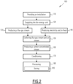
Figure 2 is a schematic block diagram of a method for carbon dioxide removal using the installation offigure 1 . -
Figure 1 shows a carbondioxide removal installation 10 according to the invention. - The carbon
dioxide removal installation 10 comprises abio-energy unit 12, a singlecarbon capture unit 14 connected to thebio-energy unit 12 and aprocessing unit 16 connected to thecarbon capture unit 14. - Optionally, the carbon
dioxide removal installation 10 comprises ablower unit 18 connected to thecarbon capture unit 14, and/or aconditioning unit 20 arranged between thecarbon capture unit 14 and theprocessing unit 16, and/or at least oneheat pump 22. - The
bio-energy unit 12 is adapted to be supplied with a quantity ofbiomass 24 and to produce aflue gas stream 26 from a combustion of the quantity ofbiomass 24. - In addition or in a variant, the
bio-energy unit 14 is adapted to be supplied with a quantity of biofuel and to produce aflue gas stream 26 from a combustion of the quantity of biofuel. - In addition or in a variant, the
bio-energy unit 14 is adapted to be supplied with a quantity of biogas and to produce aflue gas stream 26 from a combustion of the quantity of biogas. - The quantity of
biomass 24 is for example wood or wood residues. This kind ofbiomass 24 may be directly used to supply thebio-energy unit 12, or used after have been processed for example into pellets. In another variant, the quantity ofbiomass 24 comprises waste elements such as agricultural waste, municipal solid waste and/or manufacturing waste. The raw biomass may be upgraded to higher grades fuels using known methods that will not be detailed in the present application. - The quantity of biofuel is for example bioethanol produced for example from sugar beets, or biodiesel produced from vegetables oils or waste oils/fats..
- The quantity of biogas is for example produced by processing agricultural waste, municipal solid waste and/or manufacturing waste.
- The
flue gas stream 26 comprises carbon dioxide. Theflue gas stream 26 also comprises additional components such as nitrogen, water, oxygen, and unburnt elements, such as carbon monoxide, volatile organic compounds, polycyclic aromatic hydrocarbons, NOx, SOx, particulates, etc. - The concentration of carbon in volume in the
flue gas stream 26 is for example comprised between 10% and 15%. - Advantageously, the
bio-energy unit 12 is adapted to produceelectricity 28 and/orheat 30 from the combustion of the quantity ofbiomass 24 and/or the combustion of the quantity of biofuel. Thebio-energy unit 12 is adapted to partially supply thecarbon capture unit 14 withelectricity 28 and/orheat 30. - Preferably, the
bio-energy unit 12 is adapted to completely supply thecarbon capture unit 14 withelectricity 28 and /orheat 30. - In a variant, the
bio-energy unit 12 is adapted to completely supply thecarbon capture unit 14 withelectricity 28. - The
installation 10 may comprise a secondary energy unit (not represented) adapted to completely supply thecarbon capture unit 14 withheat 30. For example, the secondary energy unit is geothermal unit. - In another variant, the secondary energy unit is adapted to completely supply the
carbon capture unit 14 withelectricity 28. Thebio-energy unit 12 is adapted to completely supply thecarbon capture unit 14 withelectricity 28. - Advantageously, the
bio-energy unit 12 is adapted to supplyheat 30 and/orelectricity 28, and preferably completely supplyheat 30 and/orelectricity 28, to at least one of the units of theinstallation 10, such as theblower unit 18 and/or theconditioning unit 20. - Preferably, the
bio-energy unit 12 is adapted to completely supplyheat 30 and/orelectricity 28 to all of the units of theinstallation 10. In other words, theinstallation 10 is completely autonomous in term of energy, i.e. in term ofheat 30 andelectricity 28. - For example, the
bio-energy unit 12 comprises a boiler (not represented) adapted to combust the quantity ofbiomass 24 and to generate steam. Thebio-energy unit 12 comprises at least a steam turbine (not represented) to produceelectricity 28. - The
bio-energy unit 12 further comprises for example a heat recovery steam generator and/or a waste heat recovery unit (not represented) downstream the boiler to collect the remaining heat while cooling down theflue gas stream 26. - Preferably, the
heat pump 22 is connected to thebio-energy unit 12 and is adapted to convert at least a part of the producedelectricity 28 intoheat 30 and to supply at least one unit of theinstallation 10. For example, as depicted byFigure 1 , theheat pump 22 converts a part of the producedelectricity 28 intoheat 30 to supply thecarbon capture unit 12. - In variant or in addition,
heat 30 may be provided by a geothermal energy, and/or waste heat from a nearby facility, and/or solar thermal, etc. - The
carbon capture unit 14 is adapted to collect both at least a part of theflue gas stream 26 produced by thebio-energy unit 12 and anair stream 32 fromatmosphere 34. Thecarbon capture unit 14 is adapted to produce a carbon concentrated stream ofcarbon dioxide 36 from saidflue gas stream 26 andair stream 32. - Preferably, the
carbon capture unit 14 is adapted to collect a total flue ofgas stream 26 produced by thebio-energy unit 12. - The addition of the
air stream 32 into theflue gas stream 26 produced by thebio-energy unit 12 is particularly advantageous since it cools down theflue gas stream 26, reducing the size or eliminating the need for a direct contact cooler prior to the feeding of thecarbon unit capture 14. - The
carbon capture unit 14 is also adapted to produce awaste stream 38. Thewaste stream 38 mainly comprises nitrogen, carbon dioxide, etc. - The concentrated stream of
carbon dioxide 36 comprises in volume for example between 75% and 100% of carbon dioxide, preferably more than 99% of carbon dioxide. - The
carbon capture unit 14 is for example a post-combustion carbon dioxide capture unit based on the absorption by physical or chemical solvents, adsorption on solid media, membrane separation, cryogenics, liquefaction, etc. These technics are known for the skilled person and will be detailed here. - In a variant, the
carbon capture unit 14 is a post-combustion carbon dioxide capture unit based on a combination of at least two different technics, for example, an adsorption followed by a liquefaction to concentrate and liquefy the carbon dioxide for an efficient transport. - The
carbon capture unit 14 is adapted to separate the carbon dioxide from the additional components comprised in theflue gas stream 26 and in theair stream 32. - The
blower unit 18 is adapted to supply theair stream 32 to thecarbon capture unit 14 from theatmosphere 34. Theblower unit 18 comprises for example at least one blower (not represented). The concentration of carbon dioxide in theair stream 32 is typically around 0.04%. - The
conditioning unit 20 is adapted to condition the carbon concentratedstream 36 for a transport between thecarbon capture unit 14 and theprocessing unit 16. - Typically, the
conditioning unit 20 is adapted to condition the carbon concentratedstream 36 according to the nature of the transport used between thecarbon capture unit 14 and theprocessing unit 16. - For example, the
conditioning unit 20 is adapted to compress and dehydrate the carbon concentratedstream 36 and to put said carbon concentratedstream 36 into a liquid state or a supercritical state. - The carbon concentrated
stream 36 is then transported to theprocessing unit 16. - For example, the carbon concentrated
stream 36 is directly transported to theprocessing unit 16 for example by pipeline. When pipeline is used as mean of transport, thecarbon concentrate stream 36 is preferably in a supercritical state. - In a variant, the carbon concentrated
stream 36 is transported to theprocessing unit 16 by boat, truck and/or train. Preferably, with such a kind of means of transport, thecarbon concentrate stream 36 is in a liquid state. - According to a specific embodiment, the
installation 10 may comprise an additional concentrating unit (not represented) arranged between thecarbon capture unit 14 and theconditioning unit 20. The additional concentrating unit is adapted to further concentrate and purify thecarbon concentrate stream 36 produced by thecarbon capture unit 14. For example, the concentration of thecarbon concentrate stream 36 is made using a cryogenic distillation or using a membrane separation. - The
processing unit 16 is adapted to process the carbon concentratedstream 36. - The
processing unit 16 is for example a carbon storage unit adapted to store the carbon concentratedstream 36 into the geologic formations. - In a variant, the
processing unit 16 is a conversion unit adapted to produce at least one carbon-derived product from the carbon concentratedstream 36. - For example, the carbon-derived product is an e-fuel.
- For example, the
processing unit 16 comprises a hydrogen production unit adapted to extract hydrogen from water and to combine the produced hydrogen with the carbon concentratedstream 36 into e-fuel, preferably liquid e-fuel, such as e-jet. - In a variant, the carbon-derived product is a building material, such as a concrete. For example, the
processing unit 16 comprises a unit adapted to use the carbon concentratedstream 36 in concrete curing or mixing. - In another variant, the carbon-derived product is a polymer, for example a plastic obtained from a polyolefin made from olefins, which are polymerized into polyethylene/polypropylene.
- A
method 100 for carbon dioxide removal is now described in reference tofigure 2 . - The
method 100 comprises providing 110 aninstallation 10 as disclosed above and supplying 120 thebio-energy unit 12 with a quantity ofbiomass 24. - In a variant, the
method 100 comprises supplying thebio-energy unit 12 with at least a part of biofuel, preferably completely supplying thebio-energy unit 12 with a quantity of biofuel. - The
method 100 comprises producing 130 aflue gas stream 26 from a combustion of the quantity ofbiomass 24 and/or of biofuel. - Advantageously, the method comprises producing 140
electricity 28 and/orheat 30 from the combustion of the quantity ofbiomass 24 and/or of biofuel and/or biogas, and supplying, preferably completely, thecarbon capture unit 14 withelectricity 28 and/orheat 30 produced by thebio-energy unit 12. - Advantageously, the
method 100 comprises producing 140electricity 28 and/orheat 30 from the combustion of the quantity of biomass and/or of biofuel and/or biogas, and supplying saidheat 30 and/orelectricity 28, and preferably completely supplying at least one of the units of theinstallation 10, such as theblower unit 18 and/or theconditioning unit 20, with saidelectricity 28 and/or saidheat 30. - Preferably, the
method 100 comprises completely supplyingheat 30 and/orelectricity 28 to all of the units of the installation. In other words, no other heat source or electricity source is needed to the operation of theinstallation 10. - This step may comprise converting at least a part of the produced
electricity 28 intoheat 30 using aheat pump 22. - Then, at least a part of the
flue gas stream 26 from thebio-energy unit 12 and anair stream 32 from theatmosphere 34 are collected in a collectingstep 150. Advantageously, the totalflue gas stream 26 produced by thebio-energy unit 12 is collected. - Collecting the
air stream 32 from theatmosphere 34 may for example comprise supplying theair stream 32 to thecarbon capture unit 14 using at least one blower. - The
flue gas stream 26 and theair stream 32 are supplied to thecarbon capture unit 14 to produce a carbon concentrated stream ofcarbon dioxide 36 in a producingstep 160. Said concentratedstream 36 is then processed by theprocessing unit 16. - Preferably, before transporting the concentrated stream of
carbon dioxide 36 between thecarbon capture unit 14 and theprocessing unit 16, themethod 100 comprisesconditioning 170 the carbon concentratedstream 36. - For example, processing 180 the carbon concentrated stream of
carbon dioxide 36 comprises storing 185 the carbon concentratedstream 36 into the geologic formations, or producing at least one carbon-derived product from the carbon concentratedstream 36. - The
installation 10 according to the invention is particularly advantageous since the use of a singlecarbon capture unit 14 supplied by both direct air and by theflue gas stream 26 thebio-energy unit 12 results in lower cost and energy demand compared to installation of the prior art while allowing processing a large quantity of carbon dioxide. Moreover, the addition of theair stream 32 into theflue gas stream 26 allows cooling down saidstream 26. It allows a reduction of the size of a direct contact cooler or the elimination of the need for a direct contact cooler prior to thecarbon capture unit 14. - In the following, we illustrate an example of the implementation of the carbon
dioxide removal installation 10 according tofigure 1 to highlight the advantages of the invention. - In this example, the
bio-energy unit 12 is supplied by 246 kg of wood pellets. It produces 0.45 t of carbon dioxide with a concentration in volume of 14.3%. - The
carbon capture unit 14 is a post-combustion carbon dioxide capture unit based on the absorption using monoethanolamine (MEA). - The
carbon capture unit 14 collects thisflue gas stream 26 and 0.66 t of carbon dioxide at 0.04% in volume from atmosphere, i.e. a total of 1.11 t of carbon dioxide at 5.8% in volume. - The
carbon capture unit 14 produces a residual quantity of carbon dioxide of 0.11 t and 1 t of carbon concentratedstream 36 with a concentration of carbon dioxide at 99% in volume which can be processed, for example stored into the geologic formations. - In terms of energy, the combustion of 246 kg of wood pellets produces 198 kWh of electricity. 60 kWh supply the
blower unit carbon capture unit conditioning unit 20. 8 kWh are turned intoheat 30 by theheat pump 22 to produce 0.4 GJ and supply thecarbon capture unit 14. Thebio-energy unit 12 also produces 3.0 GJ of heat to supply thecarbon capture unit 14.
Claims (15)
- A carbon dioxide removal installation (10) comprising:- a bio-energy unit (12) adapted to be supplied with a quantity of biomass (24) and/or of biofuel and/or biogas, and to produce a flue gas stream (26) from a combustion of the quantity of biomass (24) and/or of biofuel and/or of biogas, the flue gas stream (26) comprising carbon dioxide,- a single carbon capture unit (14) adapted to collect both at least a part of the flue gas stream (26) produced by the bio-energy unit (12) and an air stream (32) from atmosphere (34), said air stream (32) comprising carbon dioxide, the carbon capture unit (14) being adapted to produce a carbon concentrated stream of carbon dioxide (36) from said flue gas stream (26) and air stream (32),- a processing unit (16) adapted to process the carbon concentrated stream of carbon dioxide (36).
- The installation (10) according to claim 1, wherein the carbon capture unit (14) is adapted to collect a total flue gas stream (26) produced by the bio-energy unit (12).
- The installation (10) according to claim 1 or 2, wherein the concentration of carbon dioxide in the flue gas stream (26) is comprised between 10% and 15%.
- The installation (10) according to any one of claim 1 to 3, wherein the bio-energy unit (12) is adapted to produce electricity (28) and/or heat (30) from the combustion of the quantity of biomass (24) and/or of biofuel and/or of biogas, and adapted to at least partially, preferably completely, supply the carbon capture unit (14) with electricity (28) and/or heat (30).
- The installation (10) according to any one of claims 1 to 4, wherein the processing unit (16) is a carbon storage unit adapted to store the carbon concentrated stream of carbon dioxide (36) into the geologic formations, or a conversion unit adapted to produce at least one carbon-derived product from the carbon concentrated stream of carbon dioxide (36).
- The installation (10) according to claim 5, wherein the carbon-derived product is chosen among an e-fuel, a building material and a plastic.
- The installation (10) according to any one of claims 1 to 6, further comprising a blower unit (18) adapted to supply the air stream (32) to the carbon capture unit (14), said blower unit (18) comprising at least one blower.
- The installation (10) according to any one of claims 1 to 7, further comprising a conditioning unit (20) adapted to condition the carbon concentrated stream of carbon dioxide (36) for a transport between the carbon capture unit (14) and the processing unit (16).
- The installation (10) according to claim 7 or 8, wherein the bio-energy unit (12) is adapted to completely supply with electricity (28) at least one unit of the installation (10) chosen among the blower unit (18) and/or the conditioning unit (20).
- The installation (10) according to any one of claims 1 to 9, further comprising a heat pump (22) to convert at least a part of the produced electricity (28) into heat (30).
- The installation (10) according to any one of claims 1 to 10, wherein the flue gas stream (26) comprises carbon dioxide and additional components, the carbon capture unit (14) being adapted to separate the carbon dioxide from the additional components.
- A method (100) for carbon dioxide removal, said method comprising the following steps:- providing (110) an installation (10) according to any one of claims 1 to 11,- supplying (120) the bio-energy unit (12) with a quantity of biomass (24) and/or of biofuel and/or of biogas,- producing (130) a flue gas stream (26) from a combustion of the quantity of biomass (24) and/or of biofuel and/or of biogas,- collecting (150) both at least a part of the flue gas stream (26) from the bio-energy unit (12) and an air stream (32) from the atmosphere (34),- producing a carbon (160) concentrated stream of carbon dioxide (36) from said flue gas stream (26) and air stream (32), and- processing (180) the carbon concentrated stream of carbon dioxide (36).
- The method (100) according to claim 12, comprising collecting (150) the total flue gas stream (26) produced by the bio-energy unit (12).
- The method (100) according to claim 12 or 13, further comprising producing (140) electricity (28) and/or heat (30) from the combustion of the quantity of biomass (24) and/or of biofuel and/or of biogas, and at least partially, preferably completely, supplying the carbon capture unit (14) with said electricity (28) and/or heat (30).
- The method (100) according to any one of claims 12 to 14, wherein processing (180) the carbon concentrated stream of carbon dioxide (36) comprises storing (185) the carbon concentrated stream of carbon dioxide (36) into the geologic formations, or producing at least one carbon-derived product from the carbon concentrated stream of carbon dioxide (36).
Priority Applications (1)
| Application Number | Priority Date | Filing Date | Title |
|---|---|---|---|
| EP21306430.6A EP4166215A1 (en) | 2021-10-12 | 2021-10-12 | A carbon dioxide removal installation and associated method |
Applications Claiming Priority (1)
| Application Number | Priority Date | Filing Date | Title |
|---|---|---|---|
| EP21306430.6A EP4166215A1 (en) | 2021-10-12 | 2021-10-12 | A carbon dioxide removal installation and associated method |
Publications (1)
| Publication Number | Publication Date |
|---|---|
| EP4166215A1 true EP4166215A1 (en) | 2023-04-19 |
Family
ID=78413905
Family Applications (1)
| Application Number | Title | Priority Date | Filing Date |
|---|---|---|---|
| EP21306430.6A Withdrawn EP4166215A1 (en) | 2021-10-12 | 2021-10-12 | A carbon dioxide removal installation and associated method |
Country Status (1)
| Country | Link |
|---|---|
| EP (1) | EP4166215A1 (en) |
Citations (7)
| Publication number | Priority date | Publication date | Assignee | Title |
|---|---|---|---|---|
| US20120219482A1 (en) * | 2011-02-25 | 2012-08-30 | Alstom Technology Ltd | Systems and processes for removing volatile degradation products produced in gas purification |
| WO2014100904A1 (en) * | 2012-12-31 | 2014-07-03 | Inventys Thermal Technologies Inc. | System and method for integrated carbon dioxide gas separation from combustion gases |
| WO2014170184A1 (en) * | 2013-04-18 | 2014-10-23 | Climeworks Ag | Low-pressure drop structure of particle adsorbent bed for adsorption gas separation process |
| US9546785B1 (en) * | 2016-06-13 | 2017-01-17 | Membrane Technology And Research, Inc. | Sweep-based membrane separation process for removing carbon dioxide from exhaust gases generated by multiple combustion sources |
| CN108339371B (en) * | 2018-01-29 | 2021-04-23 | 神华集团有限责任公司 | Apparatus and method for continuous CO2 adsorption |
| WO2021189042A1 (en) * | 2020-03-20 | 2021-09-23 | Peter Eisenberger | Novel composition of matter & carbon dioxide capture systems |
| NO20200431A1 (en) * | 2020-04-07 | 2021-10-08 | Greencap Solutions As | A method and arrangement for capturing CO2 |
-
2021
- 2021-10-12 EP EP21306430.6A patent/EP4166215A1/en not_active Withdrawn
Patent Citations (7)
| Publication number | Priority date | Publication date | Assignee | Title |
|---|---|---|---|---|
| US20120219482A1 (en) * | 2011-02-25 | 2012-08-30 | Alstom Technology Ltd | Systems and processes for removing volatile degradation products produced in gas purification |
| WO2014100904A1 (en) * | 2012-12-31 | 2014-07-03 | Inventys Thermal Technologies Inc. | System and method for integrated carbon dioxide gas separation from combustion gases |
| WO2014170184A1 (en) * | 2013-04-18 | 2014-10-23 | Climeworks Ag | Low-pressure drop structure of particle adsorbent bed for adsorption gas separation process |
| US9546785B1 (en) * | 2016-06-13 | 2017-01-17 | Membrane Technology And Research, Inc. | Sweep-based membrane separation process for removing carbon dioxide from exhaust gases generated by multiple combustion sources |
| CN108339371B (en) * | 2018-01-29 | 2021-04-23 | 神华集团有限责任公司 | Apparatus and method for continuous CO2 adsorption |
| WO2021189042A1 (en) * | 2020-03-20 | 2021-09-23 | Peter Eisenberger | Novel composition of matter & carbon dioxide capture systems |
| NO20200431A1 (en) * | 2020-04-07 | 2021-10-08 | Greencap Solutions As | A method and arrangement for capturing CO2 |
Similar Documents
| Publication | Publication Date | Title |
|---|---|---|
| Ahmed et al. | Biogas upgrading, economy and utilization: a review | |
| Favre et al. | Biogas, membranes and carbon dioxide capture | |
| Katariya et al. | Advances in biogas cleaning, enrichment, and utilization technologies: a way forward | |
| Al-Hamed et al. | A comparative review of potential ammonia-based carbon capture systems | |
| Ghorbani et al. | Investigation of a hybrid water desalination, oxy-fuel power generation and CO2 liquefaction process | |
| Persson et al. | Biogas upgrading to vehicle fuel standards and grid injection | |
| US20220065160A1 (en) | Liquid natural gas processing with hydrogen production | |
| Fendt et al. | Comparison of synthetic natural gas production pathways for the storage of renewable energy | |
| US20110023497A1 (en) | Method for Purifying Biogas | |
| US10753600B2 (en) | Turbine system and method | |
| US11446587B2 (en) | Liquid natural gas processing | |
| WO2009104820A1 (en) | Solar thermal energy storage method | |
| JP2020531258A (en) | Improved methods and systems for carbon sequestration and carbon negative power generation systems | |
| AU2011202127B2 (en) | Gas treatment and solar thermal collection system | |
| JP2020056358A (en) | Power generation system | |
| WO2017165983A1 (en) | Electrical power generation system | |
| Khan et al. | The biogas use | |
| CN116573611B (en) | A device for coupling power generation, carbon capture and inert component recovery and a method of use thereof | |
| CN106194300A (en) | A kind of industrial tail gas liquefaction energy-storing and power-generating system and electricity-generating method | |
| Perera et al. | Biogas Purification Technologies: A Comparative Review of Methods and Accessibility for Sustainable Energy Applications | |
| JP7756296B1 (en) | Carbon dioxide capture system | |
| Damle | An introduction to the utilization of membrane technology in the production of clean and renewable power | |
| De Paola et al. | Reimagining landfills as energy hubs: A new integrated approach for biomethane and green hydrogen production | |
| US20250230044A1 (en) | Stable qualified clean hydrogen production process and system | |
| US20260008974A1 (en) | Systems and methods for production of renewable hydrogen for waste collection and waste management center vehicles |
Legal Events
| Date | Code | Title | Description |
|---|---|---|---|
| PUAI | Public reference made under article 153(3) epc to a published international application that has entered the european phase |
Free format text: ORIGINAL CODE: 0009012 |
|
| STAA | Information on the status of an ep patent application or granted ep patent |
Free format text: STATUS: THE APPLICATION HAS BEEN PUBLISHED |
|
| AK | Designated contracting states |
Kind code of ref document: A1 Designated state(s): AL AT BE BG CH CY CZ DE DK EE ES FI FR GB GR HR HU IE IS IT LI LT LU LV MC MK MT NL NO PL PT RO RS SE SI SK SM TR |
|
| STAA | Information on the status of an ep patent application or granted ep patent |
Free format text: STATUS: THE APPLICATION IS DEEMED TO BE WITHDRAWN |
|
| 18D | Application deemed to be withdrawn |
Effective date: 20231020 |