EP4166087A1 - Method for determining relative positions of arrays of flexible array device - Google Patents
Method for determining relative positions of arrays of flexible array device Download PDFInfo
- Publication number
- EP4166087A1 EP4166087A1 EP21822144.8A EP21822144A EP4166087A1 EP 4166087 A1 EP4166087 A1 EP 4166087A1 EP 21822144 A EP21822144 A EP 21822144A EP 4166087 A1 EP4166087 A1 EP 4166087A1
- Authority
- EP
- European Patent Office
- Prior art keywords
- arrays
- substrate
- capacitance
- adjacent
- relative position
- Prior art date
- Legal status (The legal status is an assumption and is not a legal conclusion. Google has not performed a legal analysis and makes no representation as to the accuracy of the status listed.)
- Pending
Links
Images






Classifications
-
- A—HUMAN NECESSITIES
- A61—MEDICAL OR VETERINARY SCIENCE; HYGIENE
- A61B—DIAGNOSIS; SURGERY; IDENTIFICATION
- A61B8/00—Diagnosis using ultrasonic, sonic or infrasonic waves
- A61B8/44—Constructional features of the ultrasonic, sonic or infrasonic diagnostic device
- A61B8/4444—Constructional features of the ultrasonic, sonic or infrasonic diagnostic device related to the probe
- A61B8/4461—Features of the scanning mechanism, e.g. for moving the transducer within the housing of the probe
- A61B8/4466—Features of the scanning mechanism, e.g. for moving the transducer within the housing of the probe involving deflection of the probe
-
- A—HUMAN NECESSITIES
- A61—MEDICAL OR VETERINARY SCIENCE; HYGIENE
- A61B—DIAGNOSIS; SURGERY; IDENTIFICATION
- A61B8/00—Diagnosis using ultrasonic, sonic or infrasonic waves
- A61B8/44—Constructional features of the ultrasonic, sonic or infrasonic diagnostic device
- A61B8/4483—Constructional features of the ultrasonic, sonic or infrasonic diagnostic device characterised by features of the ultrasound transducer
-
- A—HUMAN NECESSITIES
- A61—MEDICAL OR VETERINARY SCIENCE; HYGIENE
- A61B—DIAGNOSIS; SURGERY; IDENTIFICATION
- A61B8/00—Diagnosis using ultrasonic, sonic or infrasonic waves
- A61B8/08—Clinical applications
- A61B8/0833—Clinical applications involving detecting or locating foreign bodies or organic structures
- A61B8/085—Clinical applications involving detecting or locating foreign bodies or organic structures for locating body or organic structures, e.g. tumours, calculi, blood vessels, nodules
-
- A—HUMAN NECESSITIES
- A61—MEDICAL OR VETERINARY SCIENCE; HYGIENE
- A61B—DIAGNOSIS; SURGERY; IDENTIFICATION
- A61B8/00—Diagnosis using ultrasonic, sonic or infrasonic waves
- A61B8/42—Details of probe positioning or probe attachment to the patient
- A61B8/4245—Details of probe positioning or probe attachment to the patient involving determining the position of the probe, e.g. with respect to an external reference frame or to the patient
-
- A—HUMAN NECESSITIES
- A61—MEDICAL OR VETERINARY SCIENCE; HYGIENE
- A61B—DIAGNOSIS; SURGERY; IDENTIFICATION
- A61B8/00—Diagnosis using ultrasonic, sonic or infrasonic waves
- A61B8/42—Details of probe positioning or probe attachment to the patient
- A61B8/4272—Details of probe positioning or probe attachment to the patient involving the acoustic interface between the transducer and the tissue
-
- A—HUMAN NECESSITIES
- A61—MEDICAL OR VETERINARY SCIENCE; HYGIENE
- A61B—DIAGNOSIS; SURGERY; IDENTIFICATION
- A61B8/00—Diagnosis using ultrasonic, sonic or infrasonic waves
- A61B8/44—Constructional features of the ultrasonic, sonic or infrasonic diagnostic device
- A61B8/4444—Constructional features of the ultrasonic, sonic or infrasonic diagnostic device related to the probe
- A61B8/4455—Features of the external shape of the probe, e.g. ergonomic aspects
-
- A—HUMAN NECESSITIES
- A61—MEDICAL OR VETERINARY SCIENCE; HYGIENE
- A61B—DIAGNOSIS; SURGERY; IDENTIFICATION
- A61B8/00—Diagnosis using ultrasonic, sonic or infrasonic waves
- A61B8/44—Constructional features of the ultrasonic, sonic or infrasonic diagnostic device
- A61B8/4444—Constructional features of the ultrasonic, sonic or infrasonic diagnostic device related to the probe
- A61B8/4461—Features of the scanning mechanism, e.g. for moving the transducer within the housing of the probe
-
- A—HUMAN NECESSITIES
- A61—MEDICAL OR VETERINARY SCIENCE; HYGIENE
- A61B—DIAGNOSIS; SURGERY; IDENTIFICATION
- A61B8/00—Diagnosis using ultrasonic, sonic or infrasonic waves
- A61B8/44—Constructional features of the ultrasonic, sonic or infrasonic diagnostic device
- A61B8/4477—Constructional features of the ultrasonic, sonic or infrasonic diagnostic device using several separate ultrasound transducers or probes
-
- A—HUMAN NECESSITIES
- A61—MEDICAL OR VETERINARY SCIENCE; HYGIENE
- A61B—DIAGNOSIS; SURGERY; IDENTIFICATION
- A61B8/00—Diagnosis using ultrasonic, sonic or infrasonic waves
- A61B8/44—Constructional features of the ultrasonic, sonic or infrasonic diagnostic device
- A61B8/4483—Constructional features of the ultrasonic, sonic or infrasonic diagnostic device characterised by features of the ultrasound transducer
- A61B8/4488—Constructional features of the ultrasonic, sonic or infrasonic diagnostic device characterised by features of the ultrasound transducer the transducer being a phased array
-
- A—HUMAN NECESSITIES
- A61—MEDICAL OR VETERINARY SCIENCE; HYGIENE
- A61B—DIAGNOSIS; SURGERY; IDENTIFICATION
- A61B8/00—Diagnosis using ultrasonic, sonic or infrasonic waves
- A61B8/44—Constructional features of the ultrasonic, sonic or infrasonic diagnostic device
- A61B8/4483—Constructional features of the ultrasonic, sonic or infrasonic diagnostic device characterised by features of the ultrasound transducer
- A61B8/4494—Constructional features of the ultrasonic, sonic or infrasonic diagnostic device characterised by features of the ultrasound transducer characterised by the arrangement of the transducer elements
-
- A—HUMAN NECESSITIES
- A61—MEDICAL OR VETERINARY SCIENCE; HYGIENE
- A61B—DIAGNOSIS; SURGERY; IDENTIFICATION
- A61B8/00—Diagnosis using ultrasonic, sonic or infrasonic waves
- A61B8/52—Devices using data or image processing specially adapted for diagnosis using ultrasonic, sonic or infrasonic waves
- A61B8/5207—Devices using data or image processing specially adapted for diagnosis using ultrasonic, sonic or infrasonic waves involving processing of raw data to produce diagnostic data, e.g. for generating an image
-
- B—PERFORMING OPERATIONS; TRANSPORTING
- B06—GENERATING OR TRANSMITTING MECHANICAL VIBRATIONS IN GENERAL
- B06B—METHODS OR APPARATUS FOR GENERATING OR TRANSMITTING MECHANICAL VIBRATIONS OF INFRASONIC, SONIC, OR ULTRASONIC FREQUENCY, e.g. FOR PERFORMING MECHANICAL WORK IN GENERAL
- B06B1/00—Methods or apparatus for generating mechanical vibrations of infrasonic, sonic, or ultrasonic frequency
- B06B1/02—Methods or apparatus for generating mechanical vibrations of infrasonic, sonic, or ultrasonic frequency making use of electrical energy
- B06B1/06—Methods or apparatus for generating mechanical vibrations of infrasonic, sonic, or ultrasonic frequency making use of electrical energy operating with piezoelectric effect or with electrostriction
- B06B1/0607—Methods or apparatus for generating mechanical vibrations of infrasonic, sonic, or ultrasonic frequency making use of electrical energy operating with piezoelectric effect or with electrostriction using multiple elements
- B06B1/0622—Methods or apparatus for generating mechanical vibrations of infrasonic, sonic, or ultrasonic frequency making use of electrical energy operating with piezoelectric effect or with electrostriction using multiple elements on one surface
-
- G—PHYSICS
- G01—MEASURING; TESTING
- G01B—MEASURING LENGTH, THICKNESS OR SIMILAR LINEAR DIMENSIONS; MEASURING ANGLES; MEASURING AREAS; MEASURING IRREGULARITIES OF SURFACES OR CONTOURS
- G01B7/00—Measuring arrangements characterised by the use of electric or magnetic techniques
- G01B7/14—Measuring arrangements characterised by the use of electric or magnetic techniques for measuring distance or clearance between spaced objects or spaced apertures
-
- A—HUMAN NECESSITIES
- A61—MEDICAL OR VETERINARY SCIENCE; HYGIENE
- A61B—DIAGNOSIS; SURGERY; IDENTIFICATION
- A61B2562/00—Details of sensors; Constructional details of sensor housings or probes; Accessories for sensors
- A61B2562/02—Details of sensors specially adapted for in-vivo measurements
- A61B2562/0204—Acoustic sensors
-
- A—HUMAN NECESSITIES
- A61—MEDICAL OR VETERINARY SCIENCE; HYGIENE
- A61B—DIAGNOSIS; SURGERY; IDENTIFICATION
- A61B2562/00—Details of sensors; Constructional details of sensor housings or probes; Accessories for sensors
- A61B2562/04—Arrangements of multiple sensors of the same type
- A61B2562/043—Arrangements of multiple sensors of the same type in a linear array
-
- A—HUMAN NECESSITIES
- A61—MEDICAL OR VETERINARY SCIENCE; HYGIENE
- A61B—DIAGNOSIS; SURGERY; IDENTIFICATION
- A61B2562/00—Details of sensors; Constructional details of sensor housings or probes; Accessories for sensors
- A61B2562/14—Coupling media or elements to improve sensor contact with skin or tissue
-
- A—HUMAN NECESSITIES
- A61—MEDICAL OR VETERINARY SCIENCE; HYGIENE
- A61B—DIAGNOSIS; SURGERY; IDENTIFICATION
- A61B8/00—Diagnosis using ultrasonic, sonic or infrasonic waves
- A61B8/08—Clinical applications
- A61B8/0808—Clinical applications for diagnosis of the brain
-
- B—PERFORMING OPERATIONS; TRANSPORTING
- B06—GENERATING OR TRANSMITTING MECHANICAL VIBRATIONS IN GENERAL
- B06B—METHODS OR APPARATUS FOR GENERATING OR TRANSMITTING MECHANICAL VIBRATIONS OF INFRASONIC, SONIC, OR ULTRASONIC FREQUENCY, e.g. FOR PERFORMING MECHANICAL WORK IN GENERAL
- B06B1/00—Methods or apparatus for generating mechanical vibrations of infrasonic, sonic, or ultrasonic frequency
- B06B1/02—Methods or apparatus for generating mechanical vibrations of infrasonic, sonic, or ultrasonic frequency making use of electrical energy
- B06B1/0292—Electrostatic transducers, e.g. electret-type
-
- B—PERFORMING OPERATIONS; TRANSPORTING
- B06—GENERATING OR TRANSMITTING MECHANICAL VIBRATIONS IN GENERAL
- B06B—METHODS OR APPARATUS FOR GENERATING OR TRANSMITTING MECHANICAL VIBRATIONS OF INFRASONIC, SONIC, OR ULTRASONIC FREQUENCY, e.g. FOR PERFORMING MECHANICAL WORK IN GENERAL
- B06B2201/00—Indexing scheme associated with B06B1/0207 for details covered by B06B1/0207 but not provided for in any of its subgroups
- B06B2201/70—Specific application
- B06B2201/76—Medical, dental
Definitions
- the present disclosure relates to a method for determining a relative position between arrays of a flexible array device, and more particularly, to a method for determining a relative position of arrays by measuring a change in capacitance between adjacent arrays caused by deformation (contraction, relaxation, bending) of a deformable substrate in which the plurality of arrays is arranged.
- An ultrasonic probe includes an array of ultrasonic transducers, and the ultrasonic transducer is configured to serve as both a transmitter to output an ultrasound beam to a region of interest and a receiver to receive the ultrasound beam reflected back from the object in the region of interest.
- the time of flight may be measured from the transmission/reception time of the ultrasound beam, and using this, image information of the object in the region of interest may be generated.
- the generated ultrasonic image information may be visualized through a display.
- the ultrasonic probe can image the inside of the body in a noninvasive manner and thus is widely used in the medical field.
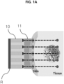
- FIG. 1A shows a cross-sectional structure of the ultrasound output device 10 according to the related art.
- the ultrasound output device 10 of FIG. 1A has an array structure in which a plurality of ultrasonic transducers is arranged at a predetermined interval. Each transducer array outputs an ultrasound beam, and the output ultrasound is reflected back to the device by an object (for example, organ tissues, tumors, cancer cells) positioned on the travel path.
- a processing device connected to the device measures the time of flight of the ultrasound beam and converts it into an image.
- the ultrasound output device includes a plurality of ultrasonic transducers arranged at a predetermined interval in a rigid substrate that does not deform, and in general, a body part to be imaged has a curved shape covered with soft skin, and the skin and the ultrasonic probe device are brought into close contact through a coupling unit 11 such as a coupling gel.
- a coupling unit 11 such as a coupling gel.
- the curve of the skin is different at each part, so even though the coupling gel is used, in some situations, it may be difficult to tightly attach the ultrasonic probe device to the skin.
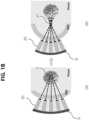
- FIG. 1B shows a cross-section structure of the flexible ultrasound output device 20 according to the related art, and it can be tightly attached to the skin more easily than FIG. 1A .
- the ultrasound output device 20 of FIG. 1B includes a plurality of ultrasonic transducers arranged at a predetermined interval in a flexible substrate that can deform arbitrarily.
- the flexible substrate is made of a material that can deform, such as, for example, polydimethylsiloxane (PDMS), and as opposed to the structure of FIG. 1A .
- PDMS polydimethylsiloxane
- the flexible substrate can be tightly attached as desired along the curve of the skin without a separate coupling unit.
- the structure of the ultrasound output device (rigid) of FIG. 1A may be used as an ultrasonic probe for imaging since the reference plane R for measuring the time of flight of an ultrasound beam does not move.
- the ultrasound output device (flexible) of FIG. 1B has a change in the position of the reference plane (R ⁇ R') and a change in the location of the focus to which the ultrasound beam converges (F ⁇ F') with movements of the skin or changes in the pressure applied to the contact surface between the skin and the device over time. Accordingly, as the reference for measuring the time of flight of the ultrasound beam changes, it is difficult to use in ultrasonic imaging applications.
- the present disclosure is directed to providing embodiments of a method for determining a relative position between each array of a flexible array device and a flexible array device using the same.
- the flexible array device includes a plurality of arrays arranged at a predetermined interval in a deformable substrate, and the method includes measuring the first capacitance between adjacent arrays, measuring the second capacitance between the adjacent arrays after deformation of the substrate, and determining a relative position between the adjacent arrays based on the first capacitance measurement value and the second capacitance measurement value.
- determining the relative position between the adjacent arrays may include calculating a distance between the adjacent arrays based on the first capacitance measurement value, and calculating a changed distance between the adjacent arrays by the deformation of the substrate based on the second capacitance measurement value.
- the dielectric constant ⁇ r of the substrate may change depending on a material of which the substrate is made, compression or tension of the substrate, and determining the relative position between the adjacent arrays may include determining the relative position between the arrays based on the capacitance measurement value between the arrays in the compression or tension.
- each of the plurality of arrays may include a first part and a second part having a smaller width than the first part, a distance between the first parts and a distance between the second parts in the adjacent arrays may be different, and the method may further include determining a bending direction of the substrate based on the capacitance between the adjacent arrays changing depending on the bending direction of the substrate.
- a flexible ultrasonic imaging apparatus includes a plurality of ultrasound output units arranged in a deformable substrate to output an ultrasound to a region of interest, an ultrasound receiving unit to receive the ultrasound reflected from an object disposed in the region of interest, and a processing unit to calculate a time of flight of the ultrasound based on a difference between an output time and a reception time of the ultrasound and acquire an image of the object based on the time of flight information, wherein the processing unit may be configured to measure first capacitance between adjacent ultrasound output units, measure second capacitance between the adjacent ultrasound output units after deformation of the substrate, determine a relative position of the plurality of ultrasound output units based on the first capacitance measurement value and the second capacitance measurement value, and correct the image of the object based on the relative position of the plurality of ultrasound output units.
- the processing unit may be configured to determine the relative position of the plurality of ultrasound output units by calculating a distance between the adjacent arrays based on the first capacitance measurement value, and calculating a changed distance between the adjacent arrays by the deformation of the substrate based on the second capacitance measurement value.
- the dielectric constant ⁇ r of the substrate may change a material of which the substrate is made, compression or tension of the substrate, and the processing unit may determine the relative position between the arrays based on the capacitance measurement value between the arrays in the compression or tension.
- the substrate may include at least two material layers having different dielectric constants
- the capacitance may be differently measured for each material layer in the adjacent arrays
- the processing unit may be further configured to determine a bending direction of the substrate based on the capacitance between the adjacent arrays changing depending on the bending direction of the substrate.
- each of the plurality of ultrasound output units may include a Micromachined Ultrasonic Transducer (MUT) and a support array to support the Micromachined Ultrasonic Transducer
- the support array may include a first part and a second part having a smaller width than the first part, a distance between the first parts and a distance between the second parts in the adjacent arrays may be different
- the processing unit may be further configured to determine a bending direction of the substrate based on the capacitance between the adjacent arrays changing depending on the bending direction of the substrate.
- a change in capacitance between adjacent arrays of the plurality of arrays arranged in the substrate caused by deformation (contraction, relaxation, bending) of a flexible substrate that can deform is measured.
- the capacitance measurement value may be used to determine a relative position between the arrays since it changes depending on the distance between the arrays and the angle between the arrays.
- the method according to an embodiment may be applied to, for example, a variety of flexible devices including ultrasonic imaging systems including flexible substrates and ultrasonic transducer arrays, ultrasound treatment systems for determining the location of the focus of focused ultrasound, sensors attached to the human body to measure changes in curvature, systems for controlling interfaces according to changes in curvature and tactile sensors, and technology using the same.
- ultrasonic imaging systems including flexible substrates and ultrasonic transducer arrays
- ultrasound treatment systems for determining the location of the focus of focused ultrasound
- sensors attached to the human body to measure changes in curvature sensors attached to the human body to measure changes in curvature
- systems for controlling interfaces according to changes in curvature and tactile sensors and technology using the same.
- FIG, 2 shows the structure of a flexible array device according to an embodiment.
- the flexible array device 30 may include a deformable substrate 300 and a plurality of arrays 301, 302, 303, ... 30n arranged at a predetermined interval in the substrate 300.
- the device may be manufactured in a suitable form for the objective and purpose and include additional components.
- a micromachined ultrasonic transducer 311 may be positioned for each array and used as an ultrasonic imaging probe or focused ultrasound treatment equipment.
- the flexible array device 30 may be manufactured by placing ultrasonic transducers (for example, micromachined ultrasonic transducers such as capacitive micromachined ultrasonic transducers (CMUTs) or piezoelectric micromachined ultrasonic transducers (PMUTs)) on a silicon substrate at a predetermined interval, patterning a photoresist thereon, etching, and filling the etched area with a flexible polymer such as polydimethylsiloxane (PDMS).
- the manufactured flexible array device 30 may be bent, compressed or relaxed by external forces.
- relative position information of each array relative to each other may be acquired by comparing the capacitance measurement values between the arrays 301, 302, 303, ... 30n of the flexible array device.
- FIGS. 3A and 3B show a change in capacitance caused by deformation (stretching, bending) of the substrate in the flexible array device according to an embodiment.
- FIG. 3A shows the substrate stretched to the left and right, and
- FIG. 3B shows the substrate bent up.
- the first capacitance C 1 between the adjacent arrays 301, 302 is measured in a non-deformed state of the flexible array device 30.
- the capacitance may be determined through a value of electric current flowing through the arrays when other variables are known. However, this is provided by way of illustration, and the capacitance may be measured through a variety of known methods in the technical field.
- the first capacitance C 1 may be calculated by the following Equation 1.
- C 1 ⁇ r ⁇ 0 t ⁇ L d
- t denotes the length in a direction perpendicular to the upper surface of the substrate 300 of the plurality of arrays (i.e., the vertical length of the arrays)
- L denotes the length in a direction parallel to the surface of the substrate 300 of the plurality of arrays (i.e., the horizontal length of the arrays)
- d denotes the distance between the adjacent arrays.
- ⁇ r and ⁇ 0 represent the dielectric constants of the substrate and vacuum, respectively.
- the distance d between the adjacent arrays 301, 302 may be calculated from the above Equation 1.
- the processing device (not shown) may be configured to receive the first capacitance measurement value in a state in which the remaining variables are inputted, and calculate the distance between the adjacent arrays in real-time.
- the second capacitance C 2 between the adjacent arrays 301, 302 is measured.
- the distance d' between the arrays 301, 302 changes, and accordingly the capacitance value between the adjacent arrays changes.
- the second capacitance C 2 may be calculated by the following Equation 2, and the distance d' between the arrays after the deformation may be calculated by comparing the measured first capacitance C 1 with the measured second capacitance C 2 .
- C 2 ⁇ r ⁇ 0 t ⁇ L d ′
- FIG. 3B shows a change in capacitance measured when the substrate 300 is bent.
- the distance d' between each array is not uniform and changes depending on the extent to which the substrate is bent (i.e., the angle between the arrays).
- the second capacitance C 2 between the adjacent arrays 301, 302 after the bending of the substrate 300 may be calculated by the following Equation 3.
- ⁇ denotes the angle between the adjacent arrays by the deformation of the substrate 300.
- t denotes the length in a direction perpendicular to the upper surface of the substrate 300 of the plurality of arrays (i.e., the vertical length of the arrays)
- L denotes the length in a direction parallel to the surface of the substrate 300 of the plurality of arrays (i.e., the horizontal length of the arrays)
- ⁇ r and ⁇ 0 are the dielectric constants of the substrate and vacuum, respectively.
- the distance between the adjacent arrays after the deformation of the substrate may be calculated by comparing the first capacitance C 1 with the second capacitance C 2 , and for all the other arrays 301, 302, 303, ... 30n, a relative position of each array relative to each other may be determined by measuring a change in capacitance.
- FIGS. 4A and 4B show the simulation results of the capacitance changing depending on the angle between two adjacent arrays.
- the capacitance when the angle between the two arrays is 0 i.e., the substrate is not bent and the two arrays are parallel
- the capacitance when the angle between the two arrays is 5° are differently measured.
- the angle and distance between the arrays may be calculated by comparing the capacitance measurement values before and after the change.
- FIG. 5 is a graph showing a change in capacitance with a change in angle between the adjacent arrays. As shown, it can be seen that when the angle between the arrays changes, the capacitance value measured between the arrays changes, and the angle between the arrays may be calculated by comparing the capacitance measurement values before and after the change.
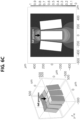
- FIGS. 6A to 6C show the simulation results of the capacitance changing depending on the pressure applied to the flexible array device according to an embodiment.
- Each array arranged in the deformable substrate in 2D array changes in position relative to each other when the pressure is applied to the substrate, and relative position information of the arrays may be acquired by comparing the capacitance measurement values between each array before and after the deformation.
- FIGS. 6A and 6B it can be seen that when the pressure is not applied to the substrate, the arrays keep parallel to each other, and when the pressure is applied to the substrate, the angle between the arrays changes and the capacitance value between the arrays changes.
- FIG. 6C It can be seen that when a higher pressure is applied to the substrate, the angle between the arrays increases and accordingly the capacitance value between the arrays changes.
- FIG. 7 shows the capacitance between the adjacent arrays changing depending on the bending direction of the substrate in the flexible array device according to an embodiment.
- the capacitance changes depending on the bending extent of the substrate irrespective of the bending direction of the substrate. That is, there is no change between the capacitance when the substrate is bent up and the capacitance when the substrate is bent down.
- each array includes a first part T and a second part B having a smaller width than the first part as shown in FIG. 7 , the distance d between the first parts T and the distance d' between the second parts B of each array are different and thus the capacitance measurement value between the adjacent arrays changes depending on the bending direction of the substrate.
- the capacitance changes depending on the bending direction of the substrate (i.e., C 2 and C 2 ' are different) and thus the bending direction of the substrate may be determined therefrom.
- FIG. 8 is a scanning electron microscopy image of the cross-sectional structure of the flexible array device according to the above-described embodiment.
- Each array is divided into the first part and the second part having a smaller width, and there is a change in the capacitance measurement value between the arrays caused by the deformation (bending, compression/relaxation) of the substrate, and thus a relative position between the arrays or the bending direction of the substrate may be determined.
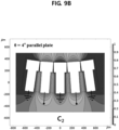
- FIGS. 9A to 9C show the simulation results of the capacitance changing depending on the bending direction of the substrate in the flexible array device according to an embodiment.
- the dielectric constant ⁇ r of the material of the flexible substrate 300 has independently a uniform constant value in each of compression and tension, but the dielectric constant ⁇ r may change with compression and tension depending on the material of the substrate 300 used in practice.
- a relative position between each array may be determined through the capacitance measurement value between the arrays in each of compression and tension.
- the substrate 300 may include at least two material layers having different dielectric constants.
- the capacitance is differently measured for each material layer in the adjacent arrays. That is, the capacitance between the adjacent arrays is different depending on the bending direction of the substrate 300, and thus using this, the bending direction of the substrate may be determined.
- the distance d between the arrays 301, 302, 303, ... 30n is equal in the first material layer 310 part and the second material layer 320 part, but due to the different dielectric constants for each material layer, the capacitance value between the adjacent arrays is differently measured from each other. That is, when the substrate 300 is bent up and when the substrate 300 is bent down, the capacitance measurement value changes (in contrast, when the substrate is made of a single material, the capacitance only changes depending on the extent of bending of the substrate irrespective of the bending direction of the substrate). Since the dielectric constant of the substrate material is known and the capacitance value can be identified from the distance between each array, the direction in which the substrate bends may be determined.
- the method for determining a relative position between arrays of a flexible array device may be implemented as an application or in the form of program instructions that may be executed through various computer components and may be recorded in computer-readable recording media.
- the computer-readable recording media may include program instructions, data files, and data structures, alone or in combination.
- Examples of the computer-readable recording media include hardware devices specially designed to store and execute program instructions, for example, magnetic media such as hard disk, floppy disk and magnetic tape, optical media such as CD-ROM and DVD, magneto-optical media such as floptical disk, and ROM, RAM and flash memory.
- the relative position between the arrays may be determined by measuring the capacitance between the adjacent arrays of the plurality of arrays arranged in the deformable substrate and measuring a change in capacitance caused by deformation (contraction, relaxation, bending) of the substrate.
- an ultrasonic probe including an ultrasonic transducer array of a flexible material may be provided.
- the ultrasonic probe is a device that outputs an ultrasound beam using a plurality of ultrasonic transducer arrays, measures the time of flight of the ultrasound beam reflected by an object positioned on the traveling path and converts it into an image.
- the reference plane of the measurement needs to be invariable over time, so a substrate of a flexible material cannot be used, and accordingly it is difficult to apply to areas having a high curvature of the contact surface or frequent movements.
- the flexible ultrasound output device including the array of ultrasonic transducers arranged in the deformable substrate (without the help of an ultrasound gel), and even when the position of the array of transducers changes with changes in the curvature of the contact surface or movements, it is possible to acquire an ultrasonic image by tracking a relative position of each array in real-time and reflecting on imaging process.
- a flexible ultrasonic imaging apparatus includes a plurality of ultrasound output units arranged in a deformable substrate to output an ultrasound to a region of interest; an ultrasound receiving unit to receive the ultrasound reflected from an object positioned in the region of interest; and a processing unit to calculate the time of flight of the ultrasound based on a difference between the output time and reception time of the ultrasound and acquire an image of the object based on the time of flight information.
- the processing unit is configured to measure the first capacitance between the adjacent ultrasound output units and the second capacitance between the adjacent ultrasound output units after deformation of the substrate, determine a relative position of the plurality of ultrasound output units based on the first capacitance measurement value and the second capacitance measurement value, and correct the image of the object based on the relative position of the plurality of ultrasound output units.
- the capacitance measurement of each ultrasound output unit may be performed through Equations 1 to 3 as described above.
- the reference plane for measuring the time of flight of ultrasound changes with curvature changes or movements of the skin, and thus it is difficult to acquire accurate images, but according to an embodiment, changes in the position of the arrays (ultrasonic transducer arrays) are reflected on the imaging process in real-time, thereby removing the influence of device deformation and acquiring accurate images.
- each of the plurality of ultrasound output units may include a Micromachined Ultrasonic Transducer (MUT) and a support array to support the Micromachined Ultrasound Transducer, and the support array may include a first part and a second part having a narrower width than the first part.
- MUT Micromachined Ultrasonic Transducer
- the support array may include a first part and a second part having a narrower width than the first part.
- the processing unit may be further configured to determine the direction in which the substrate bends based on a difference in capacitance due to the distance between the first parts of the adjacent support arrays and the distance between the second parts of the adjacent support arrays.
- each ultrasonic transducer having a curve that matches the diameter of each pipe, or to measure and correct the diameter of each pipe, but using an embodiment of the present disclosure, it can be tightly attached to the surface accurately irrespective of the type of pipes having various curves, and thus it is possible to measure the curve of the pipe, and at the same time, to measure a fault in each pipe structure via ultrasonic imaging.
- the existing flexible ultrasound output device changes in the focus location of the focused ultrasound with curvature changes or movements of the contact surface of the body (because the location of each transducer changes), making it difficult to accurately emit ultrasound to the desired point.
- HIFU high-intensity focused ultrasound
- LIFU low-intensity focused ultrasound
- the present disclosure it is possible to acquire relative position information of the array of ultrasonic transducers and track a change in the focus location of the focused ultrasound in real-time. Based on the position information, a user can arbitrarily control the direction and focus location of the ultrasound beam from each transducer array. Accordingly, it is possible to design with different response characteristics necessary for imaging diagnosis and treatment by further improving the intensity and resolution of the focus necessary for ultrasound imaging and treatment, respectively.
- a sensor including a thin flexible substrate and a plurality of arrays may be attached to the skin, and when the skin curvature changes due to joint motion, breathing and swelling, a consequential change in capacitance between the arrays may be measured, and a change in skin curvature may be identified from a change in the relative position of the arrays.
- a sensor including a thin flexible substrate and a plurality of arrays may be attached to the skin, and when the skin curvature changes due to joint motion, breathing and swelling, a consequential change in capacitance between the arrays may be measured, and a change in skin curvature may be identified from a change in the relative position of the arrays.
- it can be used as a type of wearable device which is attached to the body parts to collect repeatedly measured data such as changes in breathing, heartbeats, and pulses.
- the present disclosure may be applied to pressure sensors for input devices, for example, keyboards, based on the idea that the position of each array device is changed by the pressing pressure.
- the present disclosure may be used as wearable interface devices using changes in capacitance between arrays caused by depending on skin movements or pressing forces after attached to the skin.
- the flexible array device when used to make robotic skins, it can be used as tactile sensors that can measure the pressing pressure and sense pulling or pinching situations as if it would be human skin.
Landscapes
- Health & Medical Sciences (AREA)
- Life Sciences & Earth Sciences (AREA)
- Engineering & Computer Science (AREA)
- Physics & Mathematics (AREA)
- Molecular Biology (AREA)
- General Health & Medical Sciences (AREA)
- Nuclear Medicine, Radiotherapy & Molecular Imaging (AREA)
- Pathology (AREA)
- Radiology & Medical Imaging (AREA)
- Biomedical Technology (AREA)
- Heart & Thoracic Surgery (AREA)
- Medical Informatics (AREA)
- Veterinary Medicine (AREA)
- Surgery (AREA)
- Animal Behavior & Ethology (AREA)
- Biophysics (AREA)
- Public Health (AREA)
- Gynecology & Obstetrics (AREA)
- Computer Vision & Pattern Recognition (AREA)
- Acoustics & Sound (AREA)
- General Physics & Mathematics (AREA)
- Mechanical Engineering (AREA)
- Vascular Medicine (AREA)
- Investigating Or Analyzing Materials By The Use Of Ultrasonic Waves (AREA)
- Ultra Sonic Daignosis Equipment (AREA)
- Measurement Of Length, Angles, Or The Like Using Electric Or Magnetic Means (AREA)
Abstract
Description
- The present disclosure relates to a method for determining a relative position between arrays of a flexible array device, and more particularly, to a method for determining a relative position of arrays by measuring a change in capacitance between adjacent arrays caused by deformation (contraction, relaxation, bending) of a deformable substrate in which the plurality of arrays is arranged.
- This research is conducted by Korea Institute of Science and Technology under the support of bio-medical technology development project (Development of ultrasonic probes and attachable devices using semiconductor technology, Project Series No. 1711105874) of the Ministry of Science and ICT.
- An ultrasonic probe includes an array of ultrasonic transducers, and the ultrasonic transducer is configured to serve as both a transmitter to output an ultrasound beam to a region of interest and a receiver to receive the ultrasound beam reflected back from the object in the region of interest. The time of flight may be measured from the transmission/reception time of the ultrasound beam, and using this, image information of the object in the region of interest may be generated. The generated ultrasonic image information may be visualized through a display. The ultrasonic probe can image the inside of the body in a noninvasive manner and thus is widely used in the medical field.
-
FIG. 1A shows a cross-sectional structure of theultrasound output device 10 according to the related art. Theultrasound output device 10 ofFIG. 1A has an array structure in which a plurality of ultrasonic transducers is arranged at a predetermined interval. Each transducer array outputs an ultrasound beam, and the output ultrasound is reflected back to the device by an object (for example, organ tissues, tumors, cancer cells) positioned on the travel path. A processing device connected to the device measures the time of flight of the ultrasound beam and converts it into an image. - The ultrasound output device, as shown in
FIG. 1A , includes a plurality of ultrasonic transducers arranged at a predetermined interval in a rigid substrate that does not deform, and in general, a body part to be imaged has a curved shape covered with soft skin, and the skin and the ultrasonic probe device are brought into close contact through acoupling unit 11 such as a coupling gel. However, the curve of the skin is different at each part, so even though the coupling gel is used, in some situations, it may be difficult to tightly attach the ultrasonic probe device to the skin. -
FIG. 1B shows a cross-section structure of the flexibleultrasound output device 20 according to the related art, and it can be tightly attached to the skin more easily thanFIG. 1A . Theultrasound output device 20 ofFIG. 1B includes a plurality of ultrasonic transducers arranged at a predetermined interval in a flexible substrate that can deform arbitrarily. The flexible substrate is made of a material that can deform, such as, for example, polydimethylsiloxane (PDMS), and as opposed to the structure ofFIG. 1A . The flexible substrate can be tightly attached as desired along the curve of the skin without a separate coupling unit. - The structure of the ultrasound output device (rigid) of
FIG. 1A may be used as an ultrasonic probe for imaging since the reference plane R for measuring the time of flight of an ultrasound beam does not move. In contrast, the ultrasound output device (flexible) ofFIG. 1B has a change in the position of the reference plane (R→R') and a change in the location of the focus to which the ultrasound beam converges (F→F') with movements of the skin or changes in the pressure applied to the contact surface between the skin and the device over time. Accordingly, as the reference for measuring the time of flight of the ultrasound beam changes, it is difficult to use in ultrasonic imaging applications. - Accordingly, to acquire an ultrasonic image using a flexible material that can deform arbitrarily, there is a need for a system for determining a relative position relative to each other with the movement of the array of ultrasonic transducers in real-time and adjust the image according to position information.
- The present disclosure is directed to providing embodiments of a method for determining a relative position between each array of a flexible array device and a flexible array device using the same.
- In a method for determining a relative position between arrays of a flexible array device according to an embodiment, the flexible array device includes a plurality of arrays arranged at a predetermined interval in a deformable substrate, and the method includes measuring the first capacitance between adjacent arrays, measuring the second capacitance between the adjacent arrays after deformation of the substrate, and determining a relative position between the adjacent arrays based on the first capacitance measurement value and the second capacitance measurement value.
- According to an embodiment, determining the relative position between the adjacent arrays may include calculating a distance between the adjacent arrays based on the first capacitance measurement value, and calculating a changed distance between the adjacent arrays by the deformation of the substrate based on the second capacitance measurement value.
- According to an embodiment, the first capacitance C1 may be calculated by the following Equation, and


- According to an embodiment, the dielectric constant εr of the substrate may change depending on a material of which the substrate is made, compression or tension of the substrate, and determining the relative position between the adjacent arrays may include determining the relative position between the arrays based on the capacitance measurement value between the arrays in the compression or tension.
- According to an embodiment, each of the plurality of arrays may include a first part and a second part having a smaller width than the first part, a distance between the first parts and a distance between the second parts in the adjacent arrays may be different, and the method may further include determining a bending direction of the substrate based on the capacitance between the adjacent arrays changing depending on the bending direction of the substrate.
- There is provided a computer program stored in a computer-readable recording medium, for performing the method for determining a relative position between arrays of a flexible array device according to embodiments.
- A flexible ultrasonic imaging apparatus according to an embodiment includes a plurality of ultrasound output units arranged in a deformable substrate to output an ultrasound to a region of interest, an ultrasound receiving unit to receive the ultrasound reflected from an object disposed in the region of interest, and a processing unit to calculate a time of flight of the ultrasound based on a difference between an output time and a reception time of the ultrasound and acquire an image of the object based on the time of flight information, wherein the processing unit may be configured to measure first capacitance between adjacent ultrasound output units, measure second capacitance between the adjacent ultrasound output units after deformation of the substrate, determine a relative position of the plurality of ultrasound output units based on the first capacitance measurement value and the second capacitance measurement value, and correct the image of the object based on the relative position of the plurality of ultrasound output units.
- According to an embodiment, the processing unit may be configured to determine the relative position of the plurality of ultrasound output units by calculating a distance between the adjacent arrays based on the first capacitance measurement value, and calculating a changed distance between the adjacent arrays by the deformation of the substrate based on the second capacitance measurement value.
- According to an embodiment, the first capacitance C1 may be calculated by the following Equation, and


- According to an embodiment, the dielectric constant εr of the substrate may change a material of which the substrate is made, compression or tension of the substrate, and the processing unit may determine the relative position between the arrays based on the capacitance measurement value between the arrays in the compression or tension.
- According to an embodiment, the substrate may include at least two material layers having different dielectric constants, the capacitance may be differently measured for each material layer in the adjacent arrays, and the processing unit may be further configured to determine a bending direction of the substrate based on the capacitance between the adjacent arrays changing depending on the bending direction of the substrate.
- According to an embodiment, each of the plurality of ultrasound output units may include a Micromachined Ultrasonic Transducer (MUT) and a support array to support the Micromachined Ultrasonic Transducer, the support array may include a first part and a second part having a smaller width than the first part, a distance between the first parts and a distance between the second parts in the adjacent arrays may be different, and the processing unit may be further configured to determine a bending direction of the substrate based on the capacitance between the adjacent arrays changing depending on the bending direction of the substrate.
- According to an embodiment of the present disclosure, a change in capacitance between adjacent arrays of the plurality of arrays arranged in the substrate caused by deformation (contraction, relaxation, bending) of a flexible substrate that can deform is measured. The capacitance measurement value may be used to determine a relative position between the arrays since it changes depending on the distance between the arrays and the angle between the arrays.
- The method according to an embodiment may be applied to, for example, a variety of flexible devices including ultrasonic imaging systems including flexible substrates and ultrasonic transducer arrays, ultrasound treatment systems for determining the location of the focus of focused ultrasound, sensors attached to the human body to measure changes in curvature, systems for controlling interfaces according to changes in curvature and tactile sensors, and technology using the same.
-
-
FIG. 1A shows a cross-sectional structure of an array device including a rigid substrate and ultrasonic imaging using the same. -
FIG. 1B shows a cross-sectional structure of an array device including a flexible substrate, and a change in reference plane and focus location with a change in a curved surface. -
FIG. 2 is a perspective view showing the structure of a flexible array device according to an embodiment. -
FIGS. 3A and3B show a change in capacitance between adjacent arrays caused by deformation (stretching, bending) of a substrate in a flexible array device according to an embodiment. -
FIGS. 4A and4B show simulation results of capacitance changing depending on an angle between adjacent arrays. -
FIG. 5 is a graph showing a change in capacitance with a change in angle between adjacent arrays. -
FIGS. 6A to 6C show simulation results of capacitance changing depending on the pressure applied to a flexible array device according to an embodiment. -
FIG. 7 shows a change in capacitance between adjacent arrays depending on a bending direction of a substrate in a flexible array device according to an embodiment. -
FIG. 8 is an electron microscopy image of a cross-sectional structure of a flexible array device according to an embodiment. -
FIGS. 9A to 9C show simulation results of the capacitance changing depending on a bending direction of a substrate in a flexible array device according to an embodiment. -
FIG. 10 shows a substrate made of materials having different dielectric constants in a flexible array device according to an embodiment. - The following detailed description of the present disclosure is made with reference to the accompanying drawings, in which particular embodiments for practicing the present disclosure are shown for illustration purposes. These embodiments are described in sufficient detail for those skilled in the art to practice the present disclosure. It should be understood that various embodiments of the present disclosure are different but do not need to be mutually exclusive. For example, particular shapes, structures, and features described herein in connection with one embodiment can be embodied in other embodiment without departing from the spirit and scope of the present disclosure. It should be further understood that changes can be made to positions or placement of individual elements in each disclosed embodiment without departing from the spirit and scope of the present disclosure. Accordingly, the following detailed description is not intended to be taken in limiting senses, and the scope of the present disclosure, if appropriately described, is only defined by the appended claims along with the full scope of equivalents to which such claims are entitled. In the drawings, similar reference signs denote the same or similar functions in many aspects.
- Hereinafter, the embodiments will be described in detail with reference to the accompanying drawings, but the scope of protection is not limited or restricted by the embodiments.
-
FIG, 2 shows the structure of a flexible array device according to an embodiment. Theflexible array device 30 may include adeformable substrate 300 and a plurality ofarrays substrate 300. The device may be manufactured in a suitable form for the objective and purpose and include additional components. For example, as shown inFIG. 2 , a micromachinedultrasonic transducer 311 may be positioned for each array and used as an ultrasonic imaging probe or focused ultrasound treatment equipment. - According to an embodiment, the
flexible array device 30 may be manufactured by placing ultrasonic transducers (for example, micromachined ultrasonic transducers such as capacitive micromachined ultrasonic transducers (CMUTs) or piezoelectric micromachined ultrasonic transducers (PMUTs)) on a silicon substrate at a predetermined interval, patterning a photoresist thereon, etching, and filling the etched area with a flexible polymer such as polydimethylsiloxane (PDMS). The manufacturedflexible array device 30 may be bent, compressed or relaxed by external forces. According to an embodiment, relative position information of each array relative to each other may be acquired by comparing the capacitance measurement values between thearrays -
FIGS. 3A and3B show a change in capacitance caused by deformation (stretching, bending) of the substrate in the flexible array device according to an embodiment.FIG. 3A shows the substrate stretched to the left and right, andFIG. 3B shows the substrate bent up. - Referring to
FIG. 3A , first, the first capacitance C1 between theadjacent arrays flexible array device 30. The capacitance may be determined through a value of electric current flowing through the arrays when other variables are known. However, this is provided by way of illustration, and the capacitance may be measured through a variety of known methods in the technical field. - In this instance, the first capacitance C1 may be calculated by the following
Equation 1.
- Here, t denotes the length in a direction perpendicular to the upper surface of the
substrate 300 of the plurality of arrays (i.e., the vertical length of the arrays), L denotes the length in a direction parallel to the surface of thesubstrate 300 of the plurality of arrays (i.e., the horizontal length of the arrays), and d denotes the distance between the adjacent arrays. εr and ε0 represent the dielectric constants of the substrate and vacuum, respectively. - When the actual measurement value of the first capacitance C1 and the remaining variables are known, the distance d between the
adjacent arrays above Equation 1. According to an embodiment, the processing device (not shown) may be configured to receive the first capacitance measurement value in a state in which the remaining variables are inputted, and calculate the distance between the adjacent arrays in real-time. - Subsequently, after the
flexible array device 30 is deformed, i.e., after thesubstrate 300 is stretched to the left and right, the second capacitance C2 between theadjacent arrays FIG. 3A , when thesubstrate 300 is stretched to the left and right, the distance d' between thearrays - In this instance, the second capacitance C2 may be calculated by the following
Equation 2, and the distance d' between the arrays after the deformation may be calculated by comparing the measured first capacitance C1 with the measured second capacitance C2 .
- In this way, for all the
other arrays -
FIG. 3B shows a change in capacitance measured when thesubstrate 300 is bent. InFIG. 3A , as opposed to the substrate stretched to the left and right, the distance d' between each array is not uniform and changes depending on the extent to which the substrate is bent (i.e., the angle between the arrays). The second capacitance C2 between theadjacent arrays substrate 300 may be calculated by the followingEquation 3.
- Here, θ denotes the angle between the adjacent arrays by the deformation of the
substrate 300. t denotes the length in a direction perpendicular to the upper surface of thesubstrate 300 of the plurality of arrays (i.e., the vertical length of the arrays), L denotes the length in a direction parallel to the surface of thesubstrate 300 of the plurality of arrays (i.e., the horizontal length of the arrays), and d'denotes the distance between the adjacent arrays after the deformation of the substrate. εr and ε0 are the dielectric constants of the substrate and vacuum, respectively. - Likewise, the distance between the adjacent arrays after the deformation of the substrate may be calculated by comparing the first capacitance C1 with the second capacitance C2 , and for all the
other arrays -
FIGS. 4A and4B show the simulation results of the capacitance changing depending on the angle between two adjacent arrays. As shown inFIGS. 4A and4B , the capacitance when the angle between the two arrays is 0 (i.e., the substrate is not bent and the two arrays are parallel) and the capacitance when the angle between the two arrays is 5° are differently measured. As described above, the angle and distance between the arrays may be calculated by comparing the capacitance measurement values before and after the change. -
FIG. 5 is a graph showing a change in capacitance with a change in angle between the adjacent arrays. As shown, it can be seen that when the angle between the arrays changes, the capacitance value measured between the arrays changes, and the angle between the arrays may be calculated by comparing the capacitance measurement values before and after the change. -
FIGS. 6A to 6C show the simulation results of the capacitance changing depending on the pressure applied to the flexible array device according to an embodiment. Each array arranged in the deformable substrate in 2D array changes in position relative to each other when the pressure is applied to the substrate, and relative position information of the arrays may be acquired by comparing the capacitance measurement values between each array before and after the deformation. As shown inFIGS. 6A and6B , it can be seen that when the pressure is not applied to the substrate, the arrays keep parallel to each other, and when the pressure is applied to the substrate, the angle between the arrays changes and the capacitance value between the arrays changes. As shown inFIG. 6C , It can be seen that when a higher pressure is applied to the substrate, the angle between the arrays increases and accordingly the capacitance value between the arrays changes. -
FIG. 7 shows the capacitance between the adjacent arrays changing depending on the bending direction of the substrate in the flexible array device according to an embodiment. When the thickness of the arrays is equal over all areas, as shown inFIGS. 3A and3B , the capacitance changes depending on the bending extent of the substrate irrespective of the bending direction of the substrate. That is, there is no change between the capacitance when the substrate is bent up and the capacitance when the substrate is bent down. - In contrast, when each array includes a first part T and a second part B having a smaller width than the first part as shown in
FIG. 7 , the distance d between the first parts T and the distance d' between the second parts B of each array are different and thus the capacitance measurement value between the adjacent arrays changes depending on the bending direction of the substrate. In other words, when the thickness of the arrays is different for each zone, the capacitance changes depending on the bending direction of the substrate (i.e., C2 and C2' are different) and thus the bending direction of the substrate may be determined therefrom. -
FIG. 8 is a scanning electron microscopy image of the cross-sectional structure of the flexible array device according to the above-described embodiment. Each array is divided into the first part and the second part having a smaller width, and there is a change in the capacitance measurement value between the arrays caused by the deformation (bending, compression/relaxation) of the substrate, and thus a relative position between the arrays or the bending direction of the substrate may be determined. -
FIGS. 9A to 9C show the simulation results of the capacitance changing depending on the bending direction of the substrate in the flexible array device according to an embodiment. When each array includes the first part and the second part having a smaller width than the first part, as shown inFIGS. 9A to 9C , it can be seen that even though the extent of bending of the substrate is equal (θ = 4°), the capacitances C2 , C2' have different values depending on the bending direction of the substrate. Accordingly, the relative position between the arrays and the bending direction of the substrate are identified based on the change in the capacitance measurement value. - In the equation and the simulation, it is assumed that the dielectric constant εr of the material of the
flexible substrate 300 has independently a uniform constant value in each of compression and tension, but the dielectric constant εr may change with compression and tension depending on the material of thesubstrate 300 used in practice. Through this, a relative position between each array may be determined through the capacitance measurement value between the arrays in each of compression and tension. - According to an embodiment, the
substrate 300 may include at least two material layers having different dielectric constants. In this case, the capacitance is differently measured for each material layer in the adjacent arrays. That is, the capacitance between the adjacent arrays is different depending on the bending direction of thesubstrate 300, and thus using this, the bending direction of the substrate may be determined. - For example, when the
substrate 300 includes afirst material layer 310 and asecond material layer 320 having different dielectric constants, as shown inFIG. 10 , the distance d between thearrays first material layer 310 part and thesecond material layer 320 part, but due to the different dielectric constants for each material layer, the capacitance value between the adjacent arrays is differently measured from each other. That is, when thesubstrate 300 is bent up and when thesubstrate 300 is bent down, the capacitance measurement value changes (in contrast, when the substrate is made of a single material, the capacitance only changes depending on the extent of bending of the substrate irrespective of the bending direction of the substrate). Since the dielectric constant of the substrate material is known and the capacitance value can be identified from the distance between each array, the direction in which the substrate bends may be determined. - The method for determining a relative position between arrays of a flexible array device according to an embodiment may be implemented as an application or in the form of program instructions that may be executed through various computer components and may be recorded in computer-readable recording media. The computer-readable recording media may include program instructions, data files, and data structures, alone or in combination.
- Examples of the computer-readable recording media include hardware devices specially designed to store and execute program instructions, for example, magnetic media such as hard disk, floppy disk and magnetic tape, optical media such as CD-ROM and DVD, magneto-optical media such as floptical disk, and ROM, RAM and flash memory.
- According to the method for determining a relative position between arrays of a flexible array device as described above, the relative position between the arrays may be determined by measuring the capacitance between the adjacent arrays of the plurality of arrays arranged in the deformable substrate and measuring a change in capacitance caused by deformation (contraction, relaxation, bending) of the substrate.
- Hereinafter, an example of specific applications using the method for determining a relative position between arrays of a flexible array device will be described.
- When the method is applied to the field of ultrasonic imaging, an ultrasonic probe including an ultrasonic transducer array of a flexible material may be provided. The ultrasonic probe is a device that outputs an ultrasound beam using a plurality of ultrasonic transducer arrays, measures the time of flight of the ultrasound beam reflected by an object positioned on the traveling path and converts it into an image. To measure the time of flight of the ultrasound beam, the reference plane of the measurement needs to be invariable over time, so a substrate of a flexible material cannot be used, and accordingly it is difficult to apply to areas having a high curvature of the contact surface or frequent movements.
- According to an embodiment of the present disclosure, it can be tightly attached to any body part using the flexible ultrasound output device including the array of ultrasonic transducers arranged in the deformable substrate (without the help of an ultrasound gel), and even when the position of the array of transducers changes with changes in the curvature of the contact surface or movements, it is possible to acquire an ultrasonic image by tracking a relative position of each array in real-time and reflecting on imaging process.
- A flexible ultrasonic imaging apparatus according to an embodiment includes a plurality of ultrasound output units arranged in a deformable substrate to output an ultrasound to a region of interest; an ultrasound receiving unit to receive the ultrasound reflected from an object positioned in the region of interest; and a processing unit to calculate the time of flight of the ultrasound based on a difference between the output time and reception time of the ultrasound and acquire an image of the object based on the time of flight information.
- The processing unit is configured to measure the first capacitance between the adjacent ultrasound output units and the second capacitance between the adjacent ultrasound output units after deformation of the substrate, determine a relative position of the plurality of ultrasound output units based on the first capacitance measurement value and the second capacitance measurement value, and correct the image of the object based on the relative position of the plurality of ultrasound output units. The capacitance measurement of each ultrasound output unit may be performed through
Equations 1 to 3 as described above. - When a flexible device is tightly attached to the skin by the existing method, the reference plane for measuring the time of flight of ultrasound changes with curvature changes or movements of the skin, and thus it is difficult to acquire accurate images, but according to an embodiment, changes in the position of the arrays (ultrasonic transducer arrays) are reflected on the imaging process in real-time, thereby removing the influence of device deformation and acquiring accurate images.
- According to an embodiment, each of the plurality of ultrasound output units may include a Micromachined Ultrasonic Transducer (MUT) and a support array to support the Micromachined Ultrasound Transducer, and the support array may include a first part and a second part having a narrower width than the first part. As described above, when the width of the support arrays is equal, the capacitance changes depending on the extent to which the substrate bends irrespective of the direction in which the substrate bends, but when the width of the arrays is different, the capacitance measurement value changes depending on the direction in which the substrate bends, and thus the direction in which the substrate bends can be identified. According to an embodiment, the processing unit may be further configured to determine the direction in which the substrate bends based on a difference in capacitance due to the distance between the first parts of the adjacent support arrays and the distance between the second parts of the adjacent support arrays.
- Meanwhile, in the case of noninvasive ultrasonic testing for a curved structure such as a pipe, it is necessary to include each ultrasonic transducer having a curve that matches the diameter of each pipe, or to measure and correct the diameter of each pipe, but using an embodiment of the present disclosure, it can be tightly attached to the surface accurately irrespective of the type of pipes having various curves, and thus it is possible to measure the curve of the pipe, and at the same time, to measure a fault in each pipe structure via ultrasonic imaging.
- Additionally, in an ultrasound treatment apparatus that directly stimulates the body part using high-intensity focused ultrasound (HIFU) or low-intensity focused ultrasound (LIFU), the existing flexible ultrasound output device changes in the focus location of the focused ultrasound with curvature changes or movements of the contact surface of the body (because the location of each transducer changes), making it difficult to accurately emit ultrasound to the desired point.
- According to an embodiment of the present disclosure, it is possible to acquire relative position information of the array of ultrasonic transducers and track a change in the focus location of the focused ultrasound in real-time. Based on the position information, a user can arbitrarily control the direction and focus location of the ultrasound beam from each transducer array. Accordingly, it is possible to design with different response characteristics necessary for imaging diagnosis and treatment by further improving the intensity and resolution of the focus necessary for ultrasound imaging and treatment, respectively.
- Additionally, the present disclosure may be applied to sensors that are attached to the human body to measure changes in curvature. For example, a sensor including a thin flexible substrate and a plurality of arrays may be attached to the skin, and when the skin curvature changes due to joint motion, breathing and swelling, a consequential change in capacitance between the arrays may be measured, and a change in skin curvature may be identified from a change in the relative position of the arrays. In particular, it can be used as a type of wearable device which is attached to the body parts to collect repeatedly measured data such as changes in breathing, heartbeats, and pulses.
- Additionally, the present disclosure may be applied to pressure sensors for input devices, for example, keyboards, based on the idea that the position of each array device is changed by the pressing pressure. For example, the present disclosure may be used as wearable interface devices using changes in capacitance between arrays caused by depending on skin movements or pressing forces after attached to the skin.
- Additionally, when the flexible array device is used to make robotic skins, it can be used as tactile sensors that can measure the pressing pressure and sense pulling or pinching situations as if it would be human skin.
- While the present disclosure has been hereinabove described with reference to the embodiments, it will be understood by those having ordinary skill in the corresponding technical field that various modifications and changes may be made to the present disclosure without departing from the spirit and scope of the present disclosure as defined by the appended claims.
Claims (13)
- A method for determining a relative position between arrays of a flexible array device, in which the flexible array device includes a plurality of arrays arranged at a predetermined interval in a deformable substrate, the method comprising:measuring first capacitance between adjacent arrays;measuring second capacitance between the adjacent arrays after deformation of the substrate; anddetermining a relative position between the adjacent arrays based on the first capacitance measurement value and the second capacitance measurement value.
- The method for determining a relative position between arrays of a flexible array device according to claim 1, wherein determining the relative position between the adjacent arrays comprises:calculating a distance between the adjacent arrays based on the first capacitance measurement value; andcalculating a changed distance between the adjacent arrays by the deformation of the substrate based on the second capacitance measurement value.
- The method for determining a relative position between arrays of a flexible array device according to claim 2, wherein the first capacitance C1 is calculated by the following Equation, and


- The method for determining a relative position between arrays of a flexible array device according to claim 3, wherein the dielectric constant εr of the substrate changes depending on a material of which the substrate is made, compression or tension of the substrate, and
determining the relative position between the adjacent arrays comprises determining the relative position between the arrays based on the capacitance measurement value between the arrays in the compression or tension. - The method for determining a relative position between arrays of a flexible array device according to claim 4, wherein the substrate includes at least two material layers having different dielectric constants, and the capacitance is differently measured for each material layer in the adjacent arrays, and
the method further comprises determining a bending direction of the substrate based on the capacitance between the adjacent arrays changing depending on the bending direction of the substrate. - The method for determining a relative position between arrays of a flexible array device according to claim 1, wherein each of the plurality of arrays includes a first part and a second part having a smaller width than the first part, and a distance between the first parts and a distance between the second parts in the adjacent arrays are different, and
the method further comprises determining a bending direction of the substrate based on the capacitance between the adjacent arrays changing depending on the bending direction of the substrate. - A flexible ultrasonic imaging apparatus, comprising:a plurality of ultrasound output units arranged in a deformable substrate to output an ultrasound to a region of interest;an ultrasound receiving unit to receive the ultrasound reflected from an object disposed in the region of interest; anda processing unit to calculate a time of flight of the ultrasound based on a difference between an output time and a reception time of the ultrasound and acquire an image of the object based on the time of flight information,wherein the processing unit is configured to:measure first capacitance between adjacent ultrasound output units, measure second capacitance between the adjacent ultrasound output units after deformation of the substrate,determine a relative position of the plurality of ultrasound output units based on the first capacitance measurement value and the second capacitance measurement value, andcorrect the image of the object based on the relative position of the plurality of ultrasound output units.
- The flexible ultrasonic imaging apparatus according to claim 7, wherein the processing unit is configured to determine the relative position of the plurality of ultrasound output units by calculating a distance between the adjacent arrays based on the first capacitance measurement value, and calculating a changed distance between the adjacent arrays by the deformation of the substrate based on the second capacitance measurement value.
- The flexible ultrasonic imaging apparatus according to claim 8, wherein the first capacitance C1 is calculated by the following Equation, and


- The flexible ultrasonic imaging apparatus according to claim 9, wherein the dielectric constant εr of the substrate changes a material of which the substrate is made, compression or tension of the substrate, and
the processing unit determines the relative position between the arrays based on the capacitance measurement value between the arrays in the compression or tension. - The flexible ultrasonic imaging apparatus according to claim 10, wherein the substrate includes at least two material layers having different dielectric constants, and the capacitance is differently measured for each material layer in the adjacent arrays, and
the processing unit is further configured to determine a bending direction of the substrate based on the capacitance between the adjacent arrays changing depending on the bending direction of the substrate. - The flexible ultrasonic imaging apparatus according to claim 7, wherein each of the plurality of ultrasound output units includes a Micromachined Ultrasonic Transducer (MUT) and a support array to support the Micromachined Ultrasonic Transducer,the support array includes a first part and a second part having a smaller width than the first part, and a distance between the first parts and a distance between the second parts in the adjacent arrays are different, andthe processing unit is further configured to determine a bending direction of the substrate based on the capacitance between the adjacent arrays changing depending on the bending direction of the substrate.
- A computer program stored in a computer-readable recording medium, for performing the method for determining a relative position between arrays of a flexible array device according to any one of claims 1 to 6.
Applications Claiming Priority (2)
| Application Number | Priority Date | Filing Date | Title |
|---|---|---|---|
| KR1020200070825A KR102465348B1 (en) | 2020-06-11 | 2020-06-11 | Method for determining relative position between arrays of flexible array device |
| PCT/KR2021/001285 WO2021251582A1 (en) | 2020-06-11 | 2021-02-01 | Method for determining relative positions of arrays of flexible array device |
Publications (2)
| Publication Number | Publication Date |
|---|---|
| EP4166087A1 true EP4166087A1 (en) | 2023-04-19 |
| EP4166087A4 EP4166087A4 (en) | 2024-06-19 |
Family
ID=78845665
Family Applications (1)
| Application Number | Title | Priority Date | Filing Date |
|---|---|---|---|
| EP21822144.8A Pending EP4166087A4 (en) | 2020-06-11 | 2021-02-01 | METHOD FOR DETERMINING THE RELATIVE POSITIONS OF ARRAYS OF A FLEXIBLE ARRAY DEVICE |
Country Status (5)
| Country | Link |
|---|---|
| US (1) | US11957514B2 (en) |
| EP (1) | EP4166087A4 (en) |
| KR (1) | KR102465348B1 (en) |
| CN (1) | CN116113369B (en) |
| WO (1) | WO2021251582A1 (en) |
Families Citing this family (2)
| Publication number | Priority date | Publication date | Assignee | Title |
|---|---|---|---|---|
| KR20230106315A (en) | 2022-01-06 | 2023-07-13 | 한국과학기술연구원 | Diagnostic system using attachable patch type ultrasound transducers |
| CN118654713B (en) * | 2024-06-26 | 2025-12-02 | 浙江大学 | A multimodal, reconfigurable, and scalable interactive flexible electronic skin |
Family Cites Families (24)
| Publication number | Priority date | Publication date | Assignee | Title |
|---|---|---|---|---|
| KR970009499B1 (en) | 1994-05-30 | 1997-06-13 | Daewoo Electronics Co Ltd | A circuit for the production of the synchronized sign at a monitor |
| US5680863A (en) * | 1996-05-30 | 1997-10-28 | Acuson Corporation | Flexible ultrasonic transducers and related systems |
| JP3663501B2 (en) * | 1996-07-19 | 2005-06-22 | 神田通信工業株式会社 | Ultrasonic probe and ultrasonic inspection device |
| FR2786651B1 (en) | 1998-11-27 | 2002-10-25 | Commissariat Energie Atomique | ULTRASONIC CONTACT TRANSDUCER, WITH MULTIPLE ELEMENTS |
| US20060004290A1 (en) * | 2004-06-30 | 2006-01-05 | Smith Lowell S | Ultrasound transducer with additional sensors |
| KR20100050805A (en) * | 2008-11-06 | 2010-05-14 | (주)메디슨 | Probe of ultrasonic diagnosis apparatus |
| KR20100122202A (en) | 2009-05-12 | 2010-11-22 | 권태형 | The house which uses an air the pebble and building air air conditioning |
| JP2011010788A (en) | 2009-07-01 | 2011-01-20 | Aloka Co Ltd | Ultrasonic diagnostic system |
| KR20120090170A (en) * | 2011-02-07 | 2012-08-17 | 삼성전자주식회사 | Ultrasound measuring apparatus and controlling method thereof |
| US8665539B2 (en) * | 2011-05-11 | 2014-03-04 | Olympus Imaging Corp. | Driving control device and operation device |
| KR101362378B1 (en) | 2011-12-13 | 2014-02-13 | 삼성전자주식회사 | Probe for ultrasonic diagnostic apparatus |
| WO2013121842A1 (en) * | 2012-02-15 | 2013-08-22 | 株式会社日立製作所 | Ultrasonic imaging device |
| US10602965B2 (en) * | 2013-09-17 | 2020-03-31 | Medibotics | Wearable deformable conductive sensors for human motion capture including trans-joint pitch, yaw, and roll |
| US9228907B2 (en) * | 2013-11-14 | 2016-01-05 | Nokia Technologies Oy | Flexible device deformation measurement |
| US10241129B1 (en) * | 2014-08-01 | 2019-03-26 | Faez Ba-Tis | MEMS piston-tube based capacitive accelerometer |
| KR101654298B1 (en) | 2015-03-12 | 2016-09-05 | (주)엘라켐 | Realtime monitoring system by ultrasonography |
| JP6700916B2 (en) | 2016-03-31 | 2020-05-27 | キヤノン株式会社 | Acoustic wave probe and information acquisition device |
| WO2017182344A1 (en) * | 2016-04-19 | 2017-10-26 | Koninklijke Philips N.V. | Ultrasound transducer positioning |
| US11125547B2 (en) * | 2016-07-01 | 2021-09-21 | Sony Corporation | Sensor, sensor module, wearable terminal, and electronic device |
| US20180145643A1 (en) * | 2016-11-18 | 2018-05-24 | Sonion Nederland B.V. | Circuit for providing a high and a low impedance and a system comprising the circuit |
| US10670429B2 (en) * | 2017-02-09 | 2020-06-02 | The University Of British Columbia | Capacitive bending sensors |
| US11555731B2 (en) * | 2017-11-14 | 2023-01-17 | Rochester Sensors, Llc | TDR transducer with boomerang waveguide |
| CN110031554B (en) * | 2019-03-26 | 2021-07-23 | 深圳市理邦精密仪器股份有限公司 | Array element positioning method and device of flexible ultrasonic transducer and terminal |
| CN111184532B (en) * | 2020-04-09 | 2020-07-31 | 上海尽星生物科技有限责任公司 | Ultrasonic system and method of contact type flexible conformal ultrasonic probe |
-
2020
- 2020-06-11 KR KR1020200070825A patent/KR102465348B1/en active Active
-
2021
- 2021-02-01 WO PCT/KR2021/001285 patent/WO2021251582A1/en not_active Ceased
- 2021-02-01 EP EP21822144.8A patent/EP4166087A4/en active Pending
- 2021-02-01 US US17/273,308 patent/US11957514B2/en active Active
- 2021-02-01 CN CN202180055312.0A patent/CN116113369B/en active Active
Also Published As
| Publication number | Publication date |
|---|---|
| CN116113369B (en) | 2025-10-24 |
| CN116113369A (en) | 2023-05-12 |
| US20230086770A1 (en) | 2023-03-23 |
| WO2021251582A1 (en) | 2021-12-16 |
| EP4166087A4 (en) | 2024-06-19 |
| US11957514B2 (en) | 2024-04-16 |
| KR20210153903A (en) | 2021-12-20 |
| KR102465348B1 (en) | 2022-11-11 |
Similar Documents
| Publication | Publication Date | Title |
|---|---|---|
| US5785663A (en) | Method and device for mechanical imaging of prostate | |
| US5922018A (en) | Method for using a transrectal probe to mechanically image the prostate gland | |
| US5836894A (en) | Apparatus for measuring mechanical parameters of the prostate and for imaging the prostate using such parameters | |
| US8429982B2 (en) | Displacement measurement method and apparatus, strain measurement method and apparatus, elasticity and visco-elasticity constants measurement apparatus, and the elasticity and visco-elasticity constants measurement apparatus-based treatment apparatus | |
| US9326748B2 (en) | Clinical apparatuses | |
| US11166697B2 (en) | Systems for measuring force and torque on ultrasound probe during imaging through strain measurement | |
| US20060004290A1 (en) | Ultrasound transducer with additional sensors | |
| JP6574524B2 (en) | Imaging system and method for determining translational speed of a catheter | |
| US11957514B2 (en) | Method for determining relative position between arrays of flexible array device | |
| JP2015016144A (en) | Ultrasonic measurement apparatus, ultrasonic imaging apparatus and ultrasonic measurement method | |
| Tanaka et al. | Tactile sensor using acoustic reflection for lump detection in laparoscopic surgery | |
| CN110420058B (en) | Flexible robot with hardness detection function and detection method | |
| Takashima et al. | Development of catheter-type tactile sensor composed of polyvinylidene fluoride (PVDF) film | |
| US9078593B2 (en) | Ultrasound probe device and method of operation | |
| EP4510938B1 (en) | Method and system for determining the velocity of a natural shear wave propagating in a medium | |
| Zhang et al. | Impact of photoacoustic source location on flexible array curvature estimation with a maximum lag-one spatial coherence metric | |
| CN104899902A (en) | Method for reconstructing intravascular photoacoustic two-dimensional image | |
| Angerer et al. | A Polymer-Based CMUT Probe for Imaging the Spinal Cord in Rats | |
| Hojo et al. | Shape sensing with electrostatic differential capacitance for ultrasound imaging by flexible array transducer | |
| WO2018051577A1 (en) | Ultrasonic diagnostic device and method for controlling ultrasonic diagnostic device | |
| CN113438987A (en) | Acoustic coupling interface | |
| US20260026777A1 (en) | Method and device for locally estimating the speed of sound in a region of interest of a medium | |
| Hori et al. | Elasticity-Independent Angle Detection for Directional Palpation Using a Microfinger by Integrated Design of Flexible Strain Sensors | |
| Nagasawa et al. | TacBalloon: Soft Balloon Catheter Tactile Sensor With Simulation-Driven Learning | |
| JP2020130597A (en) | Acquisition method and measuring device for 3D reflection image inside the object to be measured |
Legal Events
| Date | Code | Title | Description |
|---|---|---|---|
| STAA | Information on the status of an ep patent application or granted ep patent |
Free format text: STATUS: THE INTERNATIONAL PUBLICATION HAS BEEN MADE |
|
| PUAI | Public reference made under article 153(3) epc to a published international application that has entered the european phase |
Free format text: ORIGINAL CODE: 0009012 |
|
| STAA | Information on the status of an ep patent application or granted ep patent |
Free format text: STATUS: REQUEST FOR EXAMINATION WAS MADE |
|
| 17P | Request for examination filed |
Effective date: 20230110 |
|
| AK | Designated contracting states |
Kind code of ref document: A1 Designated state(s): AL AT BE BG CH CY CZ DE DK EE ES FI FR GB GR HR HU IE IS IT LI LT LU LV MC MK MT NL NO PL PT RO RS SE SI SK SM TR |
|
| DAV | Request for validation of the european patent (deleted) | ||
| DAX | Request for extension of the european patent (deleted) | ||
| A4 | Supplementary search report drawn up and despatched |
Effective date: 20240516 |
|
| RIC1 | Information provided on ipc code assigned before grant |
Ipc: B06B 1/06 20060101ALI20240511BHEP Ipc: B06B 1/02 20060101ALI20240511BHEP Ipc: G01B 7/14 20060101ALI20240511BHEP Ipc: G01B 7/16 20060101ALI20240511BHEP Ipc: A61B 8/08 20060101ALI20240511BHEP Ipc: A61B 8/00 20060101AFI20240511BHEP |
|
| STAA | Information on the status of an ep patent application or granted ep patent |
Free format text: STATUS: EXAMINATION IS IN PROGRESS |
|
| 17Q | First examination report despatched |
Effective date: 20260122 |