EP4166021B1 - Electronic atomization device, atomization body and atomizer thereof, and heating control method therefor - Google Patents
Electronic atomization device, atomization body and atomizer thereof, and heating control method therefor Download PDFInfo
- Publication number
- EP4166021B1 EP4166021B1 EP22201348.4A EP22201348A EP4166021B1 EP 4166021 B1 EP4166021 B1 EP 4166021B1 EP 22201348 A EP22201348 A EP 22201348A EP 4166021 B1 EP4166021 B1 EP 4166021B1
- Authority
- EP
- European Patent Office
- Prior art keywords
- coil
- atomizer
- atomization device
- electronic atomization
- producing substrate
- Prior art date
- Legal status (The legal status is an assumption and is not a legal conclusion. Google has not performed a legal analysis and makes no representation as to the accuracy of the status listed.)
- Active
Links
Images


Classifications
-
- A—HUMAN NECESSITIES
- A24—TOBACCO; CIGARS; CIGARETTES; SIMULATED SMOKING DEVICES; SMOKERS' REQUISITES
- A24F—SMOKERS' REQUISITES; MATCH BOXES; SIMULATED SMOKING DEVICES
- A24F40/00—Electrically operated smoking devices; Component parts thereof; Manufacture thereof; Maintenance or testing thereof; Charging means specially adapted therefor
- A24F40/40—Constructional details, e.g. connection of cartridges and battery parts
- A24F40/46—Shape or structure of electric heating means
- A24F40/465—Shape or structure of electric heating means specially adapted for induction heating
-
- A—HUMAN NECESSITIES
- A24—TOBACCO; CIGARS; CIGARETTES; SIMULATED SMOKING DEVICES; SMOKERS' REQUISITES
- A24F—SMOKERS' REQUISITES; MATCH BOXES; SIMULATED SMOKING DEVICES
- A24F40/00—Electrically operated smoking devices; Component parts thereof; Manufacture thereof; Maintenance or testing thereof; Charging means specially adapted therefor
- A24F40/40—Constructional details, e.g. connection of cartridges and battery parts
-
- A—HUMAN NECESSITIES
- A24—TOBACCO; CIGARS; CIGARETTES; SIMULATED SMOKING DEVICES; SMOKERS' REQUISITES
- A24F—SMOKERS' REQUISITES; MATCH BOXES; SIMULATED SMOKING DEVICES
- A24F47/00—Smokers' requisites not otherwise provided for
-
- A—HUMAN NECESSITIES
- A24—TOBACCO; CIGARS; CIGARETTES; SIMULATED SMOKING DEVICES; SMOKERS' REQUISITES
- A24F—SMOKERS' REQUISITES; MATCH BOXES; SIMULATED SMOKING DEVICES
- A24F40/00—Electrically operated smoking devices; Component parts thereof; Manufacture thereof; Maintenance or testing thereof; Charging means specially adapted therefor
- A24F40/10—Devices using liquid inhalable precursors
Definitions
- the present disclosure relates to atomization devices, and more specifically, to an electronic atomization device, an atomization body and an atomizer thereof, and a heating control method therefor.
- An electronic atomization device is a device capable of atomizing the aerosol producing substrate in an atomizer, and has the advantages of safety, convenience, health, environmental protection and the like, and is increasingly interesting and favored by people.
- the heating of the aerosol producing substrate is generally divided into a contact heating and a non-contact heating.
- the contact heating is generally to heat a heating wire (or a heating film plated on a ceramics) directly, and two contact points need to be reserved to connect with a circuit of the heating part.
- the heating wire H1 of the atomizer 20 is in contact with two contact points P1 of the atomization body 10 through two contact points P2.
- the atomization body 10 energizes the heating wire H1 through the contact points P1 and P2, and the internal resistance of the heating wire H1 is about 1 ⁇ , and the aerosol producing substrate can be atomized when heated.
- the contact points need to be reserved, the heating mode not only has complex assembly, but also has the risk of liquid leakage. In addition, the resistances of the contact points are existed, which makes the heating efficiency low.
- the non-contact heating generally adopts electromagnetic induction to generate eddy currents for heating.
- a winding coil L1 and a capacitor (not shown) of the atomization body 10 form an LC resonant circuit, and by controlling the LC resonant circuit to achieve the most effective oscillation frequency.
- a metal heating sheet H2 (or a metal heating needle) is placed in the winding coil L1.
- the eddy currents are formed on the surfaces of the metal heating sheet H2 to achieve the purpose of heating.
- the heating efficiency is low when the heating is applied to a small-size heating member by eddy currents generated by electromagnetic induction.
- a technical problem to be resolved by the present disclosure is to provide an electronic atomization device with liquid leakage prevention and high heating efficiency, and further provide an atomization body and an atomizer thereof, and a heating control method therefor.
- a technical solution adopted by the present disclosure to resolve the technical problem is to provide an atomizer for an electronic atomization device, which is configured to accommodate aerosol producing substrate, and cooperate with an atomization body to atomize the aerosol producing substrate, the atomizer including: a first coil, configured to obtain energy from the atomization body through inductive coupling in the state where the atomizer is installed to the atomization body, so as to heat the aerosol producing substrate.
- the atomizer further includes a magnetic conductive medium, and the first coil is sleeved on the magnetic conductive medium.
- the first coil is an inductance coil
- the inductance coil includes two endpoints
- the atomizer further includes a heating member, and the two ends of the heating member are connected with the two endpoints of the first coil respectively.
- At least a portion of the heating member is disposed in the aerosol producing substrate.
- the first coil is a resistance coil wound with a heating wire, and the two ends of the first coil are short circuited.
- the first coil is disposed around the periphery of the aerosol producing substrate.
- the magnetic conductive medium includes a soft magnetic material.
- the magnetic conductive medium has a Curie point temperature, and the Curie point temperature is less than or equal to the dry burning temperature of the aerosol producing substrate.
- the Curie point temperature is 280 °C.
- the present disclosure further provides an atomization body for an electronic atomization device, which is configured to cooperate with an atomizer to atomize aerosol producing substrate, the atomization body including a second coil,
- the second coil when the atomization body is in a working state, the second coil generates electromagnetic energy, and heats the aerosol producing substrate accommodated in the atomizer through inductive coupling to generate aerosol.
- the second coil is configured to be sleeved on a magnetic conductive medium of the atomizer.
- the present disclosure further provides an electronic atomization device, including:
- the arrangement of the first coil and the second coil includes: an up-and-down arrangement, a left-and-right arrangement, or a concentric arrangement.
- the present disclosure further provides a heating control method for an electronic atomization device, including: a second coil supplying energy to a first coil in the atomizer through inductive coupling, to heat aerosol producing substrate accommodated in the atomizer to generate aerosol.
- the first coil and the second coil are sleeved on a magnetic conductive medium of the atomizer.
- the implementation of the present disclosure provides the following beneficial effects: since the atomization body is provided with a second coil, and the atomizer is provided with a first coil, and the second coil conducts electric energy to the first coil through inductive coupling, the atomizer and the atomization body no longer need to be provided with contact points for electrical connection, therefore, the liquid leakage phenomenon of the atomizer is effectively improved compared with the traditional contact (i.e., the atomizer and the atomization body are connected through the contact points) conduction of the electric energy; and the heating efficiency is greatly improved compared with the traditional non-contact conduction of the electric energy.
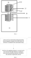
- FIG. 3 shows an electronic atomization device in a first embodiment in the present disclosure.
- the electronic atomization device in the embodiment includes an atomization body 10 and an atomizer 20 that are detachably connected.
- An aerosol producing substrate is accommodated in the atomizer 20, and the atomizer 20 is provided with a first coil 21 therein, the atomization body 10 is provided with a second coil 11 therein.
- the second coil 11 is an inductance coil composed of a common wound coil.
- the first coil 21 and the second coil 11 are arranged in an up-and-down arrangement, and are coupled with each other.
- the second coil 11 In the state when the atomizer 20 is installed to the atomization body 10, the second coil 11 generates electromagnetic energy, and the first coil 21 acquires the energy from the second coil 11 of the atomization body 10 in an inductive coupling manner, so as to heat the aerosol producing substrate in the atomizer 2 to generate aerosol.
- the first coil 21 is an inductance coil, and has two endpoints, that is, the first coil 21 is also an inductance coil composed of a common wound coil, and has a small internal resistance.
- the electronic atomization device in the embodiment further includes a heating member 22, which includes but is not limited to a heating wire or a ceramic heating core, and is connected to the two endpoints of the first coil 21. Alternatively, at least a portion of the heating member 22 may be disposed in the aerosol producing substrate.
- the second coil 11 generates electromagnetic energy when energized. According to the mutual inductance principle, the electric energy is transmitted to the first coil 21 to supply power to heating member 22, so as to realize the heating and atomizing of the aerosol producing substrate.
- the atomizer and the atomization body no longer need to be provided with the contact points for electrical connection. Therefore, compared with the traditional contact (i.e., the atomizer and the atomization body are connected through the contact points) conduction of the electric energy, the liquid leakage phenomenon of the atomizer of the electronic atomization device in the embodiment can be effectively improved. Compared with the traditional non-contact conduction of the electric energy, the heating efficiency of the electronic atomization device in the embodiment can be greatly improved.
- the electronic atomization device in the embodiment includes a magnetic conductive medium, which may be a magnetic conductive medium of a soft magnetic material, such as a magnetic conductive rod 30.
- a recess portion 23 is provided on a connecting portion of the atomizer 20 (realizing the mating installation with the atomization body 10) to accommodate the magnetic conductive rod 30.
- the second coil 11 and the first coil 21 are both sleeved on the magnetic guide rod 30.
- one magnetic conductive medium (such as the magnetic conductive rod 30) is provided between the two coils, which can increase the inductive conduction efficiency.
- FIG. 4 is the structural diagram of the electronic atomization device in the second embodiment of the present disclosure.
- the difference of the electronic atomization device of this embodiment is: the first coil 21' is a resistance coil wound by a heating wire, and has a relatively large internal resistance, and the two ends of the first coil 21' are short circuited, for example, the two ends of the first coil 21' are connected through a metal wire 22' (such as a gold wire) with a very small internal resistance, or, the two ends of the first coil 21' are directly connected together.
- the heating wire is wound into a coil to form the first coil 21', with two ends short circuited.
- the first coil 21' is arranged around a periphery of the aerosol producing substrate.
- the second coil 11 When the second coil 11 generates electromagnetic energy when energized, the electric energy is transferred to the first coil 21' according to the principle of mutual inductance, which will generate induced current on the first coil 21', and the first coil 21' will generate heat due to short circuit, so as to realize the heating and atomizing of the aerosol producing substrate.
- the magnetic conductive rod 30 is a magnetic conductive rod with a specific Curie point temperature, and the specific Curie point temperature is less than or equal to the dry burning temperature of the aerosol producing substrate.
- the magnetic conductive rod 30 is a magnetic conductive rod with a Curie point temperature of 280 °C.
- the magnetic conductive rod has the characteristic that the magnetic conductive performance disappears when the temperature rises to the Curie point temperature.
- the temperature of the heating member/wire is too high, the temperature of the magnetic conductive rod 30 extending through the heating member/wire will rise according to the conductivity of the thermal energy.
- a magnetic conductive rod with a Curie point temperature of 280 °C may be selected.
- the temperature of the magnetic conductive rod will exceed the Curie point temperature, therefore the magnetic conductive performance of the magnetic conductive rod will be greatly weakened, and the electromagnetic induction intensity of the magnetic conductive rod will be correspondingly weakened, and thus the induced current flowing through the heating member/wire will be reduced, which is not enough to provide the required power output, thereby achieving an anti-dry burning effect. Therefore, the electronic atomization device in this embodiment does not perform dry burning without providing a temperature measurement module.
- the arrangement of the first coil and the second coil may further include: a left-and-right arrangement, or a concentric arrangement.
- the electronic atomization device may be either a split electronic atomization device or an integrated electronic atomization device.
- FIG. 5 is the flow chart of the heating control method for the electronic atomization device in the first embodiment of the present disclosure. Combined with FIG. 3 or FIG. 4 , the heating control method of this embodiment includes:
- the heating control method in this embodiment adopts inductive coupling to conduct electric energy, so that the contact points for electrical connection are no longer needed on the atomizer and the atomization body. Therefore, compared with the traditional contact conduction of the electric energy, the liquid leakage phenomenon of the atomizer can be effectively improved; compared with the traditional non-contact conduction of the electric energy, the heating efficiency of the electronic atomization device in the embodiment can be greatly improved.
- the electronic atomization device may be either a split electronic atomization device or an integrated electronic atomization device.
- the arrangement of the first coil and the second coil may include: an up-and-down arrangement, a left-and-right arrangement, or a concentric arrangement.
- a magnetic conductive medium such as a magnetic conductive rod, may be provided between the first coil and the second coil.
- the magnetic conductive rod may be a magnetic conductive rod with a specific Curie point temperature, and the specific Curie point temperature is less than or equal to the dry burning temperature of the aerosol producing substrate.
Landscapes
- General Induction Heating (AREA)
- Nozzles (AREA)
- Special Spraying Apparatus (AREA)
Description
- The present disclosure relates to atomization devices, and more specifically, to an electronic atomization device, an atomization body and an atomizer thereof, and a heating control method therefor.
- An electronic atomization device is a device capable of atomizing the aerosol producing substrate in an atomizer, and has the advantages of safety, convenience, health, environmental protection and the like, and is increasingly interesting and favored by people.
- Currently, the heating of the aerosol producing substrate is generally divided into a contact heating and a non-contact heating.
- The contact heating is generally to heat a heating wire (or a heating film plated on a ceramics) directly, and two contact points need to be reserved to connect with a circuit of the heating part. As shown in
FIG. 1 , the heating wire H1 of theatomizer 20 is in contact with two contact points P1 of theatomization body 10 through two contact points P2. In the working state of the atomizer, theatomization body 10 energizes the heating wire H1 through the contact points P1 and P2, and the internal resistance of the heating wire H1 is about 1 Ω, and the aerosol producing substrate can be atomized when heated. However, since the contact points need to be reserved, the heating mode not only has complex assembly, but also has the risk of liquid leakage. In addition, the resistances of the contact points are existed, which makes the heating efficiency low. - The non-contact heating generally adopts electromagnetic induction to generate eddy currents for heating. As shown in
FIG. 2 , a winding coil L1 and a capacitor (not shown) of theatomization body 10 form an LC resonant circuit, and by controlling the LC resonant circuit to achieve the most effective oscillation frequency. A metal heating sheet H2 (or a metal heating needle) is placed in the winding coil L1. When the winding coil L1 is powered on, the eddy currents are formed on the surfaces of the metal heating sheet H2 to achieve the purpose of heating. However, the heating efficiency is low when the heating is applied to a small-size heating member by eddy currents generated by electromagnetic induction. - Publications
JP 6 741 752 B2 US 2016/120221 A1 andUS 10 945 456 B2 - A technical problem to be resolved by the present disclosure is to provide an electronic atomization device with liquid leakage prevention and high heating efficiency, and further provide an atomization body and an atomizer thereof, and a heating control method therefor.
- A technical solution adopted by the present disclosure to resolve the technical problem is to provide an atomizer for an electronic atomization device, which is configured to accommodate aerosol producing substrate, and cooperate with an atomization body to atomize the aerosol producing substrate, the atomizer including:
a first coil, configured to obtain energy from the atomization body through inductive coupling in the state where the atomizer is installed to the atomization body, so as to heat the aerosol producing substrate. The atomizer further includes a magnetic conductive medium, and the first coil is sleeved on the magnetic conductive medium. - Optionally, the first coil is an inductance coil, and the inductance coil includes two endpoints, and the atomizer further includes a heating member, and the two ends of the heating member are connected with the two endpoints of the first coil respectively.
- Optionally, at least a portion of the heating member is disposed in the aerosol producing substrate.
- Optionally, the first coil is a resistance coil wound with a heating wire, and the two ends of the first coil are short circuited.
- Optionally, the first coil is disposed around the periphery of the aerosol producing substrate.
- Optionally, the magnetic conductive medium includes a soft magnetic material.
- Optionally, the magnetic conductive medium has a Curie point temperature, and the Curie point temperature is less than or equal to the dry burning temperature of the aerosol producing substrate.
- Optionally, the Curie point temperature is 280 °C.
- The present disclosure further provides an atomization body for an electronic atomization device, which is configured to cooperate with an atomizer to atomize aerosol producing substrate, the atomization body including a second coil,
- when the atomization body is in a working state, the second coil generates electromagnetic energy, and heats the aerosol producing substrate accommodated in the atomizer through inductive coupling to generate aerosol. The second coil is configured to be sleeved on a magnetic conductive medium of the atomizer.
- The present disclosure further provides an electronic atomization device, including:
- the atomizer described above; and
- the atomization body described above.
- Optionally, the arrangement of the first coil and the second coil includes: an up-and-down arrangement, a left-and-right arrangement, or a concentric arrangement.
- The present disclosure further provides a heating control method for an electronic atomization device, including:
a second coil supplying energy to a first coil in the atomizer through inductive coupling, to heat aerosol producing substrate accommodated in the atomizer to generate aerosol. - The first coil and the second coil are sleeved on a magnetic conductive medium of the atomizer.
- The implementation of the present disclosure provides the following beneficial effects: since the atomization body is provided with a second coil, and the atomizer is provided with a first coil, and the second coil conducts electric energy to the first coil through inductive coupling, the atomizer and the atomization body no longer need to be provided with contact points for electrical connection, therefore, the liquid leakage phenomenon of the atomizer is effectively improved compared with the traditional contact (i.e., the atomizer and the atomization body are connected through the contact points) conduction of the electric energy; and the heating efficiency is greatly improved compared with the traditional non-contact conduction of the electric energy.
- Subject matter of the present disclosure will be described in even greater detail below based on the exemplary figures. In the accompanying drawings:
-
FIG. 1 is a schematic diagram of a heating mode for an aerosol producing substrate in the prior art; -
FIG. 2 is a schematic diagram of another heating mode for an aerosol producing substrate in the prior art; -
FIG. 3 is a structural diagram of an electronic atomization device in a first embodiment of the present disclosure; -
FIG. 4 is a structural diagram of an electronic atomization device in a second embodiment of the present disclosure; and -
FIG. 5 is a flowchart of a heating control method for an electronic atomization device in a first embodiment of the present disclosure. - The technical solutions in the embodiments of the present disclosure will be described in even greater detail below with reference to the accompanying drawings. Obviously, the described embodiments are merely some embodiments of the present disclosure, rather than all of the embodiments. All other embodiments obtained by a person skilled in the art based on the embodiments in the present disclosure without creative efforts shall fall within the scope of the present disclosure.
-
FIG. 3 shows an electronic atomization device in a first embodiment in the present disclosure. The electronic atomization device in the embodiment includes anatomization body 10 and anatomizer 20 that are detachably connected. An aerosol producing substrate is accommodated in theatomizer 20, and theatomizer 20 is provided with afirst coil 21 therein, theatomization body 10 is provided with asecond coil 11 therein. Wherein, thesecond coil 11 is an inductance coil composed of a common wound coil. Thefirst coil 21 and thesecond coil 11 are arranged in an up-and-down arrangement, and are coupled with each other. In the state when theatomizer 20 is installed to theatomization body 10, thesecond coil 11 generates electromagnetic energy, and thefirst coil 21 acquires the energy from thesecond coil 11 of theatomization body 10 in an inductive coupling manner, so as to heat the aerosol producing substrate in the atomizer 2 to generate aerosol. - Further, in the embodiment, combined with
FIG. 3 , thefirst coil 21 is an inductance coil, and has two endpoints, that is, thefirst coil 21 is also an inductance coil composed of a common wound coil, and has a small internal resistance. Moreover, the electronic atomization device in the embodiment further includes aheating member 22, which includes but is not limited to a heating wire or a ceramic heating core, and is connected to the two endpoints of thefirst coil 21. Alternatively, at least a portion of theheating member 22 may be disposed in the aerosol producing substrate. In the embodiment, thesecond coil 11 generates electromagnetic energy when energized. According to the mutual inductance principle, the electric energy is transmitted to thefirst coil 21 to supply power to heatingmember 22, so as to realize the heating and atomizing of the aerosol producing substrate. - In the electronic atomization device of the above embodiment, since the first coil and the second coil that are coupled with each other are provided, and the electric energy is conducted by inductive coupling, the atomizer and the atomization body no longer need to be provided with the contact points for electrical connection. Therefore, compared with the traditional contact (i.e., the atomizer and the atomization body are connected through the contact points) conduction of the electric energy, the liquid leakage phenomenon of the atomizer of the electronic atomization device in the embodiment can be effectively improved. Compared with the traditional non-contact conduction of the electric energy, the heating efficiency of the electronic atomization device in the embodiment can be greatly improved.
- Further, the electronic atomization device in the embodiment includes a magnetic conductive medium, which may be a magnetic conductive medium of a soft magnetic material, such as a magnetic
conductive rod 30. Moreover, arecess portion 23 is provided on a connecting portion of the atomizer 20 (realizing the mating installation with the atomization body 10) to accommodate the magneticconductive rod 30. In addition, thesecond coil 11 and thefirst coil 21 are both sleeved on themagnetic guide rod 30. In the embodiment, one magnetic conductive medium (such as the magnetic conductive rod 30) is provided between the two coils, which can increase the inductive conduction efficiency. -
FIG. 4 is the structural diagram of the electronic atomization device in the second embodiment of the present disclosure. Compared with the embodiment shown inFIG. 3 , the difference of the electronic atomization device of this embodiment is: the first coil 21' is a resistance coil wound by a heating wire, and has a relatively large internal resistance, and the two ends of the first coil 21' are short circuited, for example, the two ends of the first coil 21' are connected through a metal wire 22' (such as a gold wire) with a very small internal resistance, or, the two ends of the first coil 21' are directly connected together. In this embodiment, the heating wire is wound into a coil to form the first coil 21', with two ends short circuited. Alternatively, the first coil 21' is arranged around a periphery of the aerosol producing substrate. When thesecond coil 11 generates electromagnetic energy when energized, the electric energy is transferred to the first coil 21' according to the principle of mutual inductance, which will generate induced current on the first coil 21', and the first coil 21' will generate heat due to short circuit, so as to realize the heating and atomizing of the aerosol producing substrate. - Further, in an optional embodiment, the magnetic
conductive rod 30 is a magnetic conductive rod with a specific Curie point temperature, and the specific Curie point temperature is less than or equal to the dry burning temperature of the aerosol producing substrate. For example, the magneticconductive rod 30 is a magnetic conductive rod with a Curie point temperature of 280 °C. In this embodiment, the magnetic conductive rod has the characteristic that the magnetic conductive performance disappears when the temperature rises to the Curie point temperature. When the aerosol producing substrate is dry burned, the temperature of the heating member/wire is too high, the temperature of the magneticconductive rod 30 extending through the heating member/wire will rise according to the conductivity of the thermal energy. Assuming that the heating member/wire will dry burn when the temperature of which exceeds 280 °C, a magnetic conductive rod with a Curie point temperature of 280 °C may be selected. When the aerosol producing substrate is dry burned, the temperature of the magnetic conductive rod will exceed the Curie point temperature, therefore the magnetic conductive performance of the magnetic conductive rod will be greatly weakened, and the electromagnetic induction intensity of the magnetic conductive rod will be correspondingly weakened, and thus the induced current flowing through the heating member/wire will be reduced, which is not enough to provide the required power output, thereby achieving an anti-dry burning effect. Therefore, the electronic atomization device in this embodiment does not perform dry burning without providing a temperature measurement module. - It should be understood that the above is only a specific embodiment of the disclosure. In some other embodiments, the arrangement of the first coil and the second coil may further include: a left-and-right arrangement, or a concentric arrangement. In addition, the electronic atomization device may be either a split electronic atomization device or an integrated electronic atomization device.
-
FIG. 5 is the flow chart of the heating control method for the electronic atomization device in the first embodiment of the present disclosure. Combined withFIG. 3 orFIG. 4 , the heating control method of this embodiment includes: - Step S10, the second coil of the atomization body generating electromagnetic energy in a state where the atomizer is installed to the atomization body;
- Step S20, the second coil supplying energy to the first coil in the atomizer through inductive coupling, to heat the aerosol producing substrate accommodated in the atomizer to generate aerosol.
- The heating control method in this embodiment adopts inductive coupling to conduct electric energy, so that the contact points for electrical connection are no longer needed on the atomizer and the atomization body. Therefore, compared with the traditional contact conduction of the electric energy, the liquid leakage phenomenon of the atomizer can be effectively improved; compared with the traditional non-contact conduction of the electric energy, the heating efficiency of the electronic atomization device in the embodiment can be greatly improved.
- Further, the electronic atomization device may be either a split electronic atomization device or an integrated electronic atomization device. Moreover, the arrangement of the first coil and the second coil may include: an up-and-down arrangement, a left-and-right arrangement, or a concentric arrangement. In addition, a magnetic conductive medium, such as a magnetic conductive rod, may be provided between the first coil and the second coil. The magnetic conductive rod may be a magnetic conductive rod with a specific Curie point temperature, and the specific Curie point temperature is less than or equal to the dry burning temperature of the aerosol producing substrate.
Claims (12)
- An atomizer (20) for an electronic atomization device, configured to accommodate aerosol producing substrate, and cooperate with an atomization body (10) to atomize the aerosol producing substrate, comprising:
a first coil (21, 21'), configured to obtain energy from the atomization body (10) through inductive coupling in the state where the atomizer (20) is installed to the atomization body (10), so as to heat the aerosol producing substrate; and characterised in that the atomizer further comprises:a magnetic conductive medium (30);wherein the first coil (21, 21') is sleeved on the magnetic conductive medium (30). - The atomizer (20) of the electronic atomization device of claim 1, wherein the first coil (21, 21') is an inductance coil, and the inductance coil comprises two endpoints, and
wherein the atomizer (20) further comprises a heating member (22), and the two ends of the heating member (22) are connected with the two endpoints of the first coil (21, 21') respectively. - The atomizer (20) of the electronic atomization device of claim 2, wherein at least a portion of the heating member (22) is disposed in the aerosol producing substrate.
- The atomizer (20) of the electronic atomization device of claim 1, wherein the first coil (21, 21') is a resistance coil wound with a heating wire, and the two ends of the first coil (21, 21') are short circuited.
- The atomizer (20) of the electronic atomization device of claim 4, wherein the first coil (21, 21') forms a cavity, to accommodate the aerosol producing substrate.
- The atomizer (20) of the electronic atomization device of claim 1, wherein the magnetic conductive medium (30) comprises a soft magnetic material.
- The atomizer (20) of the electronic atomization device of claim 1, wherein the Curie point temperature of the magnetic conductive medium (30) is less than or equal to the dry burning temperature of the aerosol producing substrate.
- The atomizer (20) of the electronic atomization device of claim 7, wherein the Curie point temperature is 280 °C.
- An atomization body (10) for an electronic atomization device, configured to cooperate with an atomizer (20) according to any one of claims 1 to 8 to atomize aerosol producing substrate, characterized by comprising:a second coil (11), configured to generate electromagnetic energy in a working state of the atomization body (10), and to heat the aerosol producing substrate accommodated in the atomizer (20) through inductive coupling to generate aerosol,wherein the second coil (11) is configured to be sleeved on a magnetic conductive medium (30) of the atomizer (20).
- An electronic atomization device, characterized by comprising:the atomizer (20) of any one of claims 1 to 8; andthe atomization body (10) of claim 9.
- The electronic atomization device of claim 10, wherein the arrangement of the second coil (11) and the first coil (21, 21') comprises: an up-and-down arrangement, a left-and-right arrangement, or a concentric arrangement.
- A heating control method for an electronic atomization device, according to claim 10 or 11 characterized by comprising:
a second coil (11) supplying energy to a first coil (21, 21') in the atomizer (20) through inductive coupling, to heat aerosol producing substrate accommodated in the atomizer (20) to generate aerosol, wherein the first coil (21, 21') and the second coil (11) are sleeved on a magnetic conductive medium (30) of the atomizer (20).
Applications Claiming Priority (1)
| Application Number | Priority Date | Filing Date | Title |
|---|---|---|---|
| CN202111199944.2A CN113907442A (en) | 2021-10-14 | 2021-10-14 | Electronic atomization device, atomization main body thereof, atomizer and heating control method |
Publications (2)
| Publication Number | Publication Date |
|---|---|
| EP4166021A1 EP4166021A1 (en) | 2023-04-19 |
| EP4166021B1 true EP4166021B1 (en) | 2025-04-23 |
Family
ID=79240418
Family Applications (1)
| Application Number | Title | Priority Date | Filing Date |
|---|---|---|---|
| EP22201348.4A Active EP4166021B1 (en) | 2021-10-14 | 2022-10-13 | Electronic atomization device, atomization body and atomizer thereof, and heating control method therefor |
Country Status (4)
| Country | Link |
|---|---|
| EP (1) | EP4166021B1 (en) |
| JP (1) | JP2023059264A (en) |
| CN (1) | CN113907442A (en) |
| FI (1) | FI4166021T3 (en) |
Families Citing this family (4)
| Publication number | Priority date | Publication date | Assignee | Title |
|---|---|---|---|---|
| CN114504133A (en) * | 2022-02-25 | 2022-05-17 | 陈焱山 | Electronic cigarette atomization heating assembly, electronic cigarette and control method |
| CN115024522A (en) * | 2022-07-04 | 2022-09-09 | 深圳麦时科技有限公司 | Aerosol generating device and induction control device thereof |
| CN115067573B (en) * | 2022-07-15 | 2026-02-06 | 深圳麦克韦尔科技有限公司 | Electronic atomizing device |
| WO2026048030A1 (en) * | 2024-08-30 | 2026-03-05 | 日本たばこ産業株式会社 | Aerosol generation device |
Family Cites Families (10)
| Publication number | Priority date | Publication date | Assignee | Title |
|---|---|---|---|---|
| CN201445686U (en) * | 2009-06-19 | 2010-05-05 | 李文博 | High-frequency induction atomizing device |
| TWI666992B (en) * | 2014-05-21 | 2019-08-01 | 瑞士商菲利浦莫里斯製品股份有限公司 | Aerosol-generating system and cartridge for usein the aerosol-generating system |
| TWI664920B (en) * | 2014-05-21 | 2019-07-11 | 瑞士商菲利浦莫里斯製品股份有限公司 | Aerosol-forming substrate and aerosol-delivery system |
| JP2017525348A (en) * | 2014-07-24 | 2017-09-07 | アルトリア クライアント サービシーズ リミテッド ライアビリティ カンパニー | Electronic cigarette device and its parts |
| US20170055584A1 (en) * | 2015-08-31 | 2017-03-02 | British American Tobacco (Investments) Limited | Article for use with apparatus for heating smokable material |
| HUE055702T2 (en) * | 2017-08-09 | 2021-12-28 | Philip Morris Products Sa | Aerosol generation system with multiple induction coils |
| IL278583B2 (en) * | 2018-05-25 | 2024-07-01 | Philip Morris Products Sa | A heating element assembly for creating a spray that includes a heating element tube |
| US20240074504A1 (en) * | 2019-10-29 | 2024-03-07 | Fontem Ventures B.V. | Vaporizing device with induction heater |
| CN212139321U (en) * | 2020-01-10 | 2020-12-15 | 深圳市锐丽科技有限公司 | Electronic cigarette oil atomizer heated by electromagnetic induction eddy current and electronic cigarette |
| CN216453388U (en) * | 2021-10-14 | 2022-05-10 | 深圳麦克韦尔科技有限公司 | Electronic atomization device, atomization main body thereof and atomizer |
-
2021
- 2021-10-14 CN CN202111199944.2A patent/CN113907442A/en active Pending
-
2022
- 2022-10-13 EP EP22201348.4A patent/EP4166021B1/en active Active
- 2022-10-13 FI FIEP22201348.4T patent/FI4166021T3/en active
- 2022-10-13 JP JP2022164836A patent/JP2023059264A/en active Pending
Also Published As
| Publication number | Publication date |
|---|---|
| EP4166021A1 (en) | 2023-04-19 |
| FI4166021T3 (en) | 2025-06-06 |
| JP2023059264A (en) | 2023-04-26 |
| CN113907442A (en) | 2022-01-11 |
Similar Documents
| Publication | Publication Date | Title |
|---|---|---|
| EP4166021A1 (en) | Electronic atomization device, atomization body and atomizer thereof, and heating control method therefor | |
| CN216453388U (en) | Electronic atomization device, atomization main body thereof and atomizer | |
| US4745264A (en) | High efficiency autoregulating heater | |
| JP2530947B2 (en) | How to connect wires, pipes, filaments and other components | |
| US6498325B1 (en) | Modular induction heated cooking hob having reduced radiation and a method of making the same | |
| JPH07106449B2 (en) | Self-temperature control type heater | |
| CA2544647C (en) | Temperature self-regulating soldering iron with removable tip | |
| CN100380538C (en) | Composite core nonlinear reactor and induction input circuit | |
| EP1811812B1 (en) | Induction heater | |
| JPH05288131A (en) | Fuel supply device of internal combustion engine | |
| CN217316304U (en) | Resonant type gap induction heating head | |
| CN218219118U (en) | Heating components and heat-not-burn devices | |
| EP0180301B1 (en) | High efficiency autoregulating heater | |
| CN201744764U (en) | Novel vortex electric soldering iron | |
| CN110429918B (en) | Structure for forming series resonance by bonding transformer, capacitor and inductor | |
| CN114433974A (en) | Resonant type gap induction heating head | |
| CN208939667U (en) | An electromagnetic device for a wireless power transfer system | |
| CN121545892A (en) | A toroidal transformer | |
| CN201418165Y (en) | Multi-functional flexible induction heater | |
| CN214509418U (en) | Atomizing device's heating element and this atomizing device | |
| CN112790441A (en) | A heating element of an atomizing device | |
| CN222531856U (en) | A heat generating device for improving heat conversion efficiency | |
| JP7749092B2 (en) | atomizer | |
| CN205945589U (en) | Laser energy supply is energy conversion module for system | |
| CN216723153U (en) | Induction heating assembly and aerosol generating device |
Legal Events
| Date | Code | Title | Description |
|---|---|---|---|
| PUAI | Public reference made under article 153(3) epc to a published international application that has entered the european phase |
Free format text: ORIGINAL CODE: 0009012 |
|
| STAA | Information on the status of an ep patent application or granted ep patent |
Free format text: STATUS: THE APPLICATION HAS BEEN PUBLISHED |
|
| AK | Designated contracting states |
Kind code of ref document: A1 Designated state(s): AL AT BE BG CH CY CZ DE DK EE ES FI FR GB GR HR HU IE IS IT LI LT LU LV MC ME MK MT NL NO PL PT RO RS SE SI SK SM TR |
|
| STAA | Information on the status of an ep patent application or granted ep patent |
Free format text: STATUS: REQUEST FOR EXAMINATION WAS MADE |
|
| 17P | Request for examination filed |
Effective date: 20230829 |
|
| RBV | Designated contracting states (corrected) |
Designated state(s): AL AT BE BG CH CY CZ DE DK EE ES FI FR GB GR HR HU IE IS IT LI LT LU LV MC ME MK MT NL NO PL PT RO RS SE SI SK SM TR |
|
| RAP3 | Party data changed (applicant data changed or rights of an application transferred) |
Owner name: SHENZHEN SMOORE TECHNOLOGY LIMITED |
|
| GRAP | Despatch of communication of intention to grant a patent |
Free format text: ORIGINAL CODE: EPIDOSNIGR1 |
|
| STAA | Information on the status of an ep patent application or granted ep patent |
Free format text: STATUS: GRANT OF PATENT IS INTENDED |
|
| GRAS | Grant fee paid |
Free format text: ORIGINAL CODE: EPIDOSNIGR3 |
|
| INTG | Intention to grant announced |
Effective date: 20250218 |
|
| GRAA | (expected) grant |
Free format text: ORIGINAL CODE: 0009210 |
|
| STAA | Information on the status of an ep patent application or granted ep patent |
Free format text: STATUS: THE PATENT HAS BEEN GRANTED |
|
| AK | Designated contracting states |
Kind code of ref document: B1 Designated state(s): AL AT BE BG CH CY CZ DE DK EE ES FI FR GB GR HR HU IE IS IT LI LT LU LV MC ME MK MT NL NO PL PT RO RS SE SI SK SM TR |
|
| P01 | Opt-out of the competence of the unified patent court (upc) registered |
Free format text: CASE NUMBER: APP_13299/2025 Effective date: 20250318 |
|
| REG | Reference to a national code |
Ref country code: GB Ref legal event code: FG4D |
|
| REG | Reference to a national code |
Ref country code: CH Ref legal event code: EP |
|
| REG | Reference to a national code |
Ref country code: DE Ref legal event code: R096 Ref document number: 602022013476 Country of ref document: DE |
|
| RAP4 | Party data changed (patent owner data changed or rights of a patent transferred) |
Owner name: SHENZHEN SMOORE TECHNOLOGY LIMITED |
|
| REG | Reference to a national code |
Ref country code: IE Ref legal event code: FG4D |
|
| REG | Reference to a national code |
Ref country code: FI Ref legal event code: FGE |
|
| REG | Reference to a national code |
Ref country code: SK Ref legal event code: T3 Ref document number: E 46303 Country of ref document: SK |
|
| REG | Reference to a national code |
Ref country code: NL Ref legal event code: MP Effective date: 20250423 |
|
| PG25 | Lapsed in a contracting state [announced via postgrant information from national office to epo] |
Ref country code: NL Free format text: LAPSE BECAUSE OF FAILURE TO SUBMIT A TRANSLATION OF THE DESCRIPTION OR TO PAY THE FEE WITHIN THE PRESCRIBED TIME-LIMIT Effective date: 20250423 |
|
| REG | Reference to a national code |
Ref country code: AT Ref legal event code: MK05 Ref document number: 1786874 Country of ref document: AT Kind code of ref document: T Effective date: 20250423 |
|
| PG25 | Lapsed in a contracting state [announced via postgrant information from national office to epo] |
Ref country code: PT Free format text: LAPSE BECAUSE OF FAILURE TO SUBMIT A TRANSLATION OF THE DESCRIPTION OR TO PAY THE FEE WITHIN THE PRESCRIBED TIME-LIMIT Effective date: 20250825 Ref country code: ES Free format text: LAPSE BECAUSE OF FAILURE TO SUBMIT A TRANSLATION OF THE DESCRIPTION OR TO PAY THE FEE WITHIN THE PRESCRIBED TIME-LIMIT Effective date: 20250423 |
|
| REG | Reference to a national code |
Ref country code: LT Ref legal event code: MG9D |
|
| PG25 | Lapsed in a contracting state [announced via postgrant information from national office to epo] |
Ref country code: NO Free format text: LAPSE BECAUSE OF FAILURE TO SUBMIT A TRANSLATION OF THE DESCRIPTION OR TO PAY THE FEE WITHIN THE PRESCRIBED TIME-LIMIT Effective date: 20250723 Ref country code: GR Free format text: LAPSE BECAUSE OF FAILURE TO SUBMIT A TRANSLATION OF THE DESCRIPTION OR TO PAY THE FEE WITHIN THE PRESCRIBED TIME-LIMIT Effective date: 20250724 |
|
| PG25 | Lapsed in a contracting state [announced via postgrant information from national office to epo] |
Ref country code: PL Free format text: LAPSE BECAUSE OF FAILURE TO SUBMIT A TRANSLATION OF THE DESCRIPTION OR TO PAY THE FEE WITHIN THE PRESCRIBED TIME-LIMIT Effective date: 20250423 |
|
| PG25 | Lapsed in a contracting state [announced via postgrant information from national office to epo] |
Ref country code: BG Free format text: LAPSE BECAUSE OF FAILURE TO SUBMIT A TRANSLATION OF THE DESCRIPTION OR TO PAY THE FEE WITHIN THE PRESCRIBED TIME-LIMIT Effective date: 20250423 |
|
| PG25 | Lapsed in a contracting state [announced via postgrant information from national office to epo] |
Ref country code: HR Free format text: LAPSE BECAUSE OF FAILURE TO SUBMIT A TRANSLATION OF THE DESCRIPTION OR TO PAY THE FEE WITHIN THE PRESCRIBED TIME-LIMIT Effective date: 20250423 |
|
| PG25 | Lapsed in a contracting state [announced via postgrant information from national office to epo] |
Ref country code: AT Free format text: LAPSE BECAUSE OF FAILURE TO SUBMIT A TRANSLATION OF THE DESCRIPTION OR TO PAY THE FEE WITHIN THE PRESCRIBED TIME-LIMIT Effective date: 20250423 |
|
| PG25 | Lapsed in a contracting state [announced via postgrant information from national office to epo] |
Ref country code: RS Free format text: LAPSE BECAUSE OF FAILURE TO SUBMIT A TRANSLATION OF THE DESCRIPTION OR TO PAY THE FEE WITHIN THE PRESCRIBED TIME-LIMIT Effective date: 20250723 |
|
| PG25 | Lapsed in a contracting state [announced via postgrant information from national office to epo] |
Ref country code: IS Free format text: LAPSE BECAUSE OF FAILURE TO SUBMIT A TRANSLATION OF THE DESCRIPTION OR TO PAY THE FEE WITHIN THE PRESCRIBED TIME-LIMIT Effective date: 20250823 |
|
| PG25 | Lapsed in a contracting state [announced via postgrant information from national office to epo] |
Ref country code: LV Free format text: LAPSE BECAUSE OF FAILURE TO SUBMIT A TRANSLATION OF THE DESCRIPTION OR TO PAY THE FEE WITHIN THE PRESCRIBED TIME-LIMIT Effective date: 20250423 |
|
| PG25 | Lapsed in a contracting state [announced via postgrant information from national office to epo] |
Ref country code: DK Free format text: LAPSE BECAUSE OF FAILURE TO SUBMIT A TRANSLATION OF THE DESCRIPTION OR TO PAY THE FEE WITHIN THE PRESCRIBED TIME-LIMIT Effective date: 20250423 Ref country code: SM Free format text: LAPSE BECAUSE OF FAILURE TO SUBMIT A TRANSLATION OF THE DESCRIPTION OR TO PAY THE FEE WITHIN THE PRESCRIBED TIME-LIMIT Effective date: 20250423 |
|
| PGFP | Annual fee paid to national office [announced via postgrant information from national office to epo] |
Ref country code: IT Payment date: 20251031 Year of fee payment: 4 Ref country code: FI Payment date: 20251024 Year of fee payment: 4 |
|
| PGFP | Annual fee paid to national office [announced via postgrant information from national office to epo] |
Ref country code: CZ Payment date: 20251007 Year of fee payment: 4 |
|
| PG25 | Lapsed in a contracting state [announced via postgrant information from national office to epo] |
Ref country code: EE Free format text: LAPSE BECAUSE OF FAILURE TO SUBMIT A TRANSLATION OF THE DESCRIPTION OR TO PAY THE FEE WITHIN THE PRESCRIBED TIME-LIMIT Effective date: 20250423 |
|
| REG | Reference to a national code |
Ref country code: DE Ref legal event code: R097 Ref document number: 602022013476 Country of ref document: DE |
|
| PGFP | Annual fee paid to national office [announced via postgrant information from national office to epo] |
Ref country code: RO Payment date: 20251009 Year of fee payment: 4 Ref country code: SK Payment date: 20251006 Year of fee payment: 4 |
|
| PLBE | No opposition filed within time limit |
Free format text: ORIGINAL CODE: 0009261 |
|
| STAA | Information on the status of an ep patent application or granted ep patent |
Free format text: STATUS: NO OPPOSITION FILED WITHIN TIME LIMIT |
|
| REG | Reference to a national code |
Ref country code: CH Ref legal event code: L10 Free format text: ST27 STATUS EVENT CODE: U-0-0-L10-L00 (AS PROVIDED BY THE NATIONAL OFFICE) Effective date: 20260304 |
|
| 26N | No opposition filed |
Effective date: 20260126 |