EP4166014A1 - Atomizer, electronic atomization device, and sealing element for atomizer - Google Patents
Atomizer, electronic atomization device, and sealing element for atomizer Download PDFInfo
- Publication number
- EP4166014A1 EP4166014A1 EP21826222.8A EP21826222A EP4166014A1 EP 4166014 A1 EP4166014 A1 EP 4166014A1 EP 21826222 A EP21826222 A EP 21826222A EP 4166014 A1 EP4166014 A1 EP 4166014A1
- Authority
- EP
- European Patent Office
- Prior art keywords
- section
- side wall
- seal element
- porous body
- along
- Prior art date
- Legal status (The legal status is an assumption and is not a legal conclusion. Google has not performed a legal analysis and makes no representation as to the accuracy of the status listed.)
- Granted
Links
Images


Classifications
-
- A—HUMAN NECESSITIES
- A24—TOBACCO; CIGARS; CIGARETTES; SIMULATED SMOKING DEVICES; SMOKERS' REQUISITES
- A24F—SMOKERS' REQUISITES; MATCH BOXES; SIMULATED SMOKING DEVICES
- A24F40/00—Electrically operated smoking devices; Component parts thereof; Manufacture thereof; Maintenance or testing thereof; Charging means specially adapted therefor
- A24F40/40—Constructional details, e.g. connection of cartridges and battery parts
-
- A—HUMAN NECESSITIES
- A24—TOBACCO; CIGARS; CIGARETTES; SIMULATED SMOKING DEVICES; SMOKERS' REQUISITES
- A24F—SMOKERS' REQUISITES; MATCH BOXES; SIMULATED SMOKING DEVICES
- A24F40/00—Electrically operated smoking devices; Component parts thereof; Manufacture thereof; Maintenance or testing thereof; Charging means specially adapted therefor
- A24F40/40—Constructional details, e.g. connection of cartridges and battery parts
- A24F40/48—Fluid transfer means, e.g. pumps
- A24F40/485—Valves; Apertures
-
- A—HUMAN NECESSITIES
- A24—TOBACCO; CIGARS; CIGARETTES; SIMULATED SMOKING DEVICES; SMOKERS' REQUISITES
- A24F—SMOKERS' REQUISITES; MATCH BOXES; SIMULATED SMOKING DEVICES
- A24F40/00—Electrically operated smoking devices; Component parts thereof; Manufacture thereof; Maintenance or testing thereof; Charging means specially adapted therefor
- A24F40/10—Devices using liquid inhalable precursors
-
- A—HUMAN NECESSITIES
- A24—TOBACCO; CIGARS; CIGARETTES; SIMULATED SMOKING DEVICES; SMOKERS' REQUISITES
- A24F—SMOKERS' REQUISITES; MATCH BOXES; SIMULATED SMOKING DEVICES
- A24F40/00—Electrically operated smoking devices; Component parts thereof; Manufacture thereof; Maintenance or testing thereof; Charging means specially adapted therefor
- A24F40/40—Constructional details, e.g. connection of cartridges and battery parts
- A24F40/42—Cartridges or containers for inhalable precursors
-
- A—HUMAN NECESSITIES
- A24—TOBACCO; CIGARS; CIGARETTES; SIMULATED SMOKING DEVICES; SMOKERS' REQUISITES
- A24F—SMOKERS' REQUISITES; MATCH BOXES; SIMULATED SMOKING DEVICES
- A24F40/00—Electrically operated smoking devices; Component parts thereof; Manufacture thereof; Maintenance or testing thereof; Charging means specially adapted therefor
- A24F40/40—Constructional details, e.g. connection of cartridges and battery parts
- A24F40/44—Wicks
Definitions
- Embodiments of this application relate to the field of e-cigarette technologies, and in particular, to an atomizer, an electronic atomization device, and a seal element for an atomizer.
- Tobacco products (such as cigarettes and cigars) burn tobacco during use to produce tobacco smoke. Attempts are made to replace these tobacco-burning products by manufacturing products that release compounds without being burnt.
- An example of such a product is an electronic atomization device. These devices usually contain a liquid, and the liquid is heated to atomize, so as to generate an inhalable vapor or an aerosol.
- the liquid may contain nicotine, and/or aromatics, and/or aerosol-generation substances (such as glycerin).
- a porous body is generally used to absorb the liquid, and the liquid is heated by a heating element combined on the porous body to generate the aerosol.
- the porous body is usually wrapped by a seal element to prevent the liquid from causing seepage from a surface of the porous body, and there is an assembly gap between an existing seal element and the porous body, which affects the sealing effect.
- Embodiments of this application aim at providing an atomizer, an electronic atomization device, and a seal element for an atomizer, so as to resolve or at least partially resolve the problem in the related art that there is an assembly gap between the seal element and the porous body, which affects the sealing effect.
- an atomizer including:
- a liquid guide hole is arranged on the seal element, and the porous body is in fluid communication with the liquid storage cavity through the liquid guide hole; and the liquid guide hole is located in the at least one closed ring.
- the convex ribs are symmetrically arranged along a length direction and/or a width direction of the seal element.
- the convex ribs comprise several sections, and the several sections are connected end to end successively to form the at least one closed ring.
- any two adjacent sections of the several sections of the convex ribs are basically perpendicular to each other.
- the porous body has a liquid channel that runs through the porous body along a length direction, and is in fluid communication with the liquid storage cavity through the liquid channel; and the convex ribs avoid the liquid channel.
- the plurality of side walls include at least a first side wall and a second side wall opposite to each other along the length direction of the seal element, and a third side wall and a fourth side wall opposite to each other along the width direction of the seal element.
- the convex ribs include:
- the first convex rib includes a first section arranged on the first side wall and a second section arranged on the second side wall;
- the first convex rib includes a first section arranged on the first side wall and a second section arranged on the second side wall;
- the third section and/or the fourth section extend(s) along the width direction of the seal element.
- At least a part of the third convex rib and/or the fourth convex rib is arranged obliquely.
- the porous body has a first direction, a second direction perpendicular to the first direction, and a third direction perpendicular to the first direction and the second direction;
- the porous body includes a base part, and the base part is arranged parallel to the second direction and the third direction, and is provided with a liquid absorption surface and an atomization surface facing away from each other along the first direction;
- the porous body further includes a first extension arm and a second extension arm extending from the base part away from the atomization surface, and a support part extending between the first extension arm and the second extension arm; and the first extension arm and the second extension arm are parallel to the second direction, and are arranged opposite to each other along the third direction.
- the first convex rib is opposite to at least a part of the base part
- the convex ribs include:
- the convex ribs include:
- This application further provides an electronic atomization device, including an atomization device, and a power supply device configured to supply power to the atomization device, where the atomization device includes the foregoing atomizer.
- This application further provides a seal element for an atomizer, the seal element including a plurality of side walls and an upper end wall, where the seal element includes several convex ribs extending on outer surfaces of the plurality of side walls and the upper end wall or on inner surfaces of the plurality of side walls and the upper end wall, and the several convex ribs are connected into at least one closed ring.
- the seal element is arranged between the holder and the porous body, and by arranging the convex ribs extending on the outer surfaces of the plurality of side walls and the upper end wall or on the inner surfaces of the plurality of side walls and the upper end wall in the seal element, the seal element can seal the porous body and the holder through the convex ribs after assembly.
- the electronic atomization device includes: an atomizer 100, configured to store a liquid substrate and atomize the liquid substrate to generate an aerosol; and a power supply mechanism 200, configured to supply power to the atomizer 100.
- the power supply mechanism 200 includes: a receiving cavity 270, arranged at an end along a length direction, and configured to receive and accommodate at least a part of the atomizer 100; and a first electrical contact 230, at least partially exposed on a surface of the receiving cavity 270, and configured to be electrically connected to the atomizer 100 to supply power to the atomizer 100 when at least a part of the atomizer 100 is received and accommodated in the power supply mechanism 200.
- an end portion of the atomizer 100 opposite to the power supply mechanism 200 along the length direction is provided with a second electrical contact 21, so that when at least a part of the atomizer 100 is received in the receiving cavity 270, the second electrical contact 21 forms conductivity through being in contact with and abutting against the first electrical contact 230.
- a seal element 260 is arranged inside the power supply mechanism 200, and at least a part of an internal space of the power supply mechanism 200 is separated through the seal element 260 to form the receiving cavity 270.
- the seal element 260 is configured to extend along a cross section direction of the power supply mechanism 200, and is preferably prepared by a flexible material such as silica gel, so as to prevent the liquid substrate seeping from the atomizer 100 to the receiving cavity 270 from flowing to a controller 220, a sensor 250, and other components inside the power supply mechanism 200.
- the power supply mechanism 200 further includes: a battery cell 210, located at another end facing away from the receiving cavity 270 along the length direction, and configured to supply power; and a controller 220, arranged between the battery cell 210 and an accommodating cavity, and operably guiding a current between the battery cell 210 and the first electrical contact 230.
- the power supply mechanism 200 includes a sensor 250, configured to sense an inhalation flow generated by the atomizer 100 during inhalation, so that the controller 220 controls the battery cell 210 to output the current to the atomizer 100 according to a detection signal of the sensor 250.
- a charging interface 240 is arranged on another end of the power supply mechanism 200 facing away from the receiving cavity 270, and is configured to supply power to the battery cell 210.
- the embodiments in FIG. 2 to FIG. 5 are schematic structural diagrams of an embodiment of the atomizer 100 in FIG. 1 .
- the atomizer 100 includes: a main housing 10.
- the main housing 10 is generally in a flat cylindrical shape; and the main housing 10 has a near end 110 and a far end 120 opposite to each other along the length direction.
- the near end 110 is configured as an end for the user to inhale the aerosol, and a suction nozzle A for the user to inhale is arranged on the near end 110; and the far end 120 is used as an end combined with the power supply mechanism 200, and the far end 120 of the main housing 10 is an opening on which a detachable end cap 20 is installed.
- the opening structure is configured to install necessary functional components inside the main housing 10.
- the second electrical contact 21 is penetrated into the atomizer 100 from a surface of the end cap 20, so that at least a part of the second electrical contact 21 is exposed outside the atomizer 100, so as to form conductivity through being in contact with the first electrical contact 230.
- the end cap 20 is further provided with a first air inlet 23, configured to supply external air into the atomizer 100 during inhalation.
- the atomizer 100 further includes a magnetic element 22, penetrating into the atomizer 100 from the surface of the end cap 20, and configured to stabilize the atomizer 100 in the receiving cavity 270 through magnetic adsorption when the atomizer 100 is received in the receiving cavity 270.
- the main housing 10 is internally provided with a liquid storage cavity 12 for storing the liquid substrate, and an atomization assembly for absorbing the liquid substrate from the liquid storage cavity 12, and heating and atomizing the liquid substrate.
- the atomization assembly generally includes a capillary liquid guide element for absorbing the liquid substrate, and a heating element combined with the liquid guide element.
- the heating element heats at least a part of the liquid substrate in the liquid guide element to generate the aerosol during power on.
- the liquid guide element includes flexible fibers such as cotton fibers, non-woven fabrics, and glass fiber ropes, or includes porous materials with a microporous structure, such as porous ceramics.
- the heating element can be combined onto the liquid guide element or wound on the liquid guide element through printing, deposition, sintering, physical assembly, or the like.
- the atomization assembly includes: a porous body 30, configured to absorb and transfer the liquid substrate; and a heating element 40, configured to heat and atomize the liquid substrate absorbed by the porous body 30.
- the main housing 10 is internally provided with a flue gas transmission pipe 11 arranged along an axial direction; and the main housing 10 is further internally provided with a liquid storage cavity 12 configured to store the liquid substrate.
- the flue gas transmission pipe 11 extends in the liquid storage cavity 12, and the liquid storage cavity 12 is formed by the space between an outer wall of the flue gas transmission pipe 11 and an inner wall of the main housing 10.
- a first end of the flue gas transmission pipe 11 opposite to the near end 110 is in communication with the suction nozzle A, and a second end opposite to the far end 120 is in airflow connection with an atomization chamber 340 formed by defining between an atomization surface 310 of the porous body 30 and the end cap 20, so as to transmit the aerosol generated by the atomized liquid substrate in the heating element 40 and released to the atomization chamber 340 to the suction nozzle A for inhalation.
- the shape of the porous body 30 is configured to be, but not limited to, generally a block structure in the embodiment.
- the porous body 30 includes the atomization surface 310 which is arched in shape and faces the end cap 20 along the axial direction of the main housing 10.
- a side of the porous body 30 facing away from the atomization surface 310 is in fluid communication with the liquid storage cavity 12, so as to absorb the liquid substrate, then the microporous structure inside the porous body 30 transmits the liquid substrate to the atomization surface 310 to be heated and atomized to form the aerosol, and the formed aerosol is released or escaping from the atomization surface 310.
- the heating element 40 is formed on the atomization surface 310; and after assembly, the second electrical contact 21 abuts against the heating element 40, so as to supply power to the heating element 40.
- the main housing 10 is further provided with a flexible seal element 50, a holder 60 and a flexible first seal element 70, which not only seals an opening of the liquid storage cavity 12, but also fixes and holds the porous body 30 inside.
- the flexible seal element 50 is generally in a hollow cylinder shape.
- the inner hollow is configured to accommodate the porous body 30, and is sleeved outside the porous body 30 in a close fitting manner.
- the rigid holder 60 holds the porous body 30 sleeved with the flexible seal element 50.
- the holder 60 may generally have an annular shape with an open lower end.
- a holding space 64 is configured to accommodate and hold the flexible seal element 50 and the porous body 30.
- the flexible seal element 50 can seal a gap between the porous body 30 and the holder 60 to prevent the liquid substrate from seeping out of the gap between them; and on the other hand, the flexible seal element 50 is located between the porous body 30 and the holder 60, which is advantageous for the porous body 30 to be stably accommodated in the holder 60 to avoid from loosening.
- the flexible first seal element 70 is arranged between the liquid storage cavity 12 and the holder 60, and the shape of the flexible first seal element 70 is adapted to the cross section of the inner contour of the main housing 10, so as to seal the liquid storage cavity 12 and prevent the liquid substrate from leaking out of the liquid storage cavity 12. Further, in order to prevent the shrinkage and deformation of the first seal element 70 made of the flexible materials from affecting the tightness of the sealing, the holder 60 is accommodated in the flexible first seal element 70 to provide support for the first seal element 70.
- the flexible first seal element 70 is provided with a first liquid guide hole 71 for the liquid substrate to flow through
- the holder 60 is correspondingly provided with a second liquid guide hole 61
- the flexible seal element 50 is provided with a liquid guide hole 51.
- the liquid substrate in the liquid storage cavity 12 flows to the porous body 30 held in the flexible seal element 50 via the first liquid guide hole 71, the second liquid guide hole 61, and the liquid guide hole 51 successively as shown by arrow R1 in FIG. 4 and FIG. 5 , then the liquid substrate is absorbed and transferred to the atomization surface 310 for atomization, and the generated aerosol is released into the atomization chamber 340 defined between the atomization surface 310 and the end cap 20.
- the flexible first seal element 70 is provided with a first insertion hole 72 for a lower end of the flue gas transmission pipe 11 to plug in
- the holder 60 is correspondingly provided with a second insertion hole 62
- an opposite side of the holder 60 to the main housing 10 is provided with an aerosol output channel 63 through which the atomization surface 310 is in airflow communication with the second insertion hole 62.
- a complete inhalation flow path after installation is shown by arrow R2 in FIG. 4 .
- the external air enters the atomization chamber 340 via the first air inlet 23 on the end cap 20, then carries the generated aerosol to flow from the aerosol output channel 63 to the second insertion hole 62, and then outputs to the flue gas transmission pipe 11 via the first insertion hole 72.
- the porous body 30 is arched in shape and has a first side portion 31 and a second side portion 32 opposite to each other along a thickness direction, and a base part 34 extending between the first side portion 31 and the second side portion 32; and a lower surface of the base part 34 is configured as an atomization surface 310.
- the first side portion 31 and the second side portion 32 extend along a length direction of the porous body 30.
- a liquid channel 33 extending along the length direction of the porous body 30 is defined among the first side portion 31, the second side portion 32, and the base part 34, and the liquid substrate flowing via the first liquid guide hole 71, the second liquid guide hole 61, and the liquid guide hole 51 is received and absorbed through the liquid channel 33.
- the porous body 30 further includes a support part 35 extending along a cross section direction of the atomizer 100 between the first side portion 31 and the second side portion 32.
- the seal element 50 is generally in a hollow cylinder shape, and the inner hollow is an accommodating cavity configured to accommodate and wrap the porous body 30, so as to be wrapped outside the porous body 30 after assembly.
- An inner surface of the seal element 50 is provided with several convex ribs 52 configured to improve the sealing effect after installation.
- These convex ribs 52 are mainly configured to seal the gap between the holder 60 and the porous body 30 to prevent leakage from the gap between the holder 60 and the porous body 30 in the process of liquid transmission. Therefore, in the implementation, the several convex ribs 52 form into a closed ring shape together, which completely surrounds or wraps the liquid transmission channel, so as to achieve a better sealing effect.
- the structure of the seal element 50 is shown in FIG. 7 and FIG. 8 .
- the seal element 50 is in a square cylinder shape with an open lower end.
- An inner wall of the accommodating cavity formed by the seal element 50 to accommodate and surround the porous body 30 include:
- the convex ribs 52 on an inner wall of the seal element 50 include:
- the convex ribs 52 have eight sections in total, and are connected to form a closed shape by connecting end to end successively.
- the above closed ring formed by the convex ribs 52 is a non-planar closed ring having a span along a length direction of the atomizer 100.
- the liquid guide hole 51 is located in the closed ring formed by the convex ribs 52.
- the inner upper wall 550 of the seal element 50 is provided with positioning cantilevers 53 on two sides along the length direction.
- the positioning cantilevers 53 extend longitudinally.
- the two positioning cantilevers 53 respectively clamp or fit the support part 35 of the porous body 30 from two sides, so as to facilitate the auxiliary guidance and positioning during their assembly.
- FIG. 10 and FIG. 11 show schematic structural diagrams of a seal element 50a according to another embodiment.
- convex ribs 52a on an inner wall of the seal element 50a include: a first section 521a, a second section 522a, a third section 523a, a fourth section 524a, a fifth section 525a, and a sixth section 526a connected end to end successively to form a first closed ring surrounding a liquid guide hole 51a; and a seventh section 5210a, an eighth section 5220a, a ninth section 5230a, a tenth section 5240a, an eleventh section 5250a, and a twelfth section 5260a connected end to end successively to form a second closed ring surrounding another liquid guide hole 52a.
- the first closed ring is close to a first inner side wall 510a
- the second closed ring is close to a second inner side wall 520a.
- the fourth section 524a and the tenth section 5240a both abut against or fit the support part 35 of the porous body 30 to form an interference fit.
- the fourth section 524a and the tenth section 5240a are respectively arranged on two sides of the inner upper wall 550a along a length direction of the seal element 50a.
- FIG. 12 shows a schematic structural diagram of a seal element 50b in another embodiment; convex ribs 52b thereof have a ninth section 529b extending along the width direction between a third section 523b and a seventh section 527b, and the ninth section 529b divides the closed ring formed through successively connecting a first section 521b to an eighth section 528b into two annular parts respectively surrounding a liquid guide hole 51b.
- each section of the convex ribs 52/52a/52b after assembly can be supported by the porous body 30, so as to stably form an interference fit to seal gaps between the convex ribs and between the porous body 30 and the holder 60.
- the seal element 50 made of silica gel and the holder 60 made of organic polymer plastic are obtained by injection molding together in the mold through premolding, such as double-color injection molding; and the seal element 50 is molded and combined into an inner wall of the holding space 64 of the holder 60 directly through premolding, such as a double-color injection molding process.
- FIG. 14 shows a schematic structural diagram of a seal element 50c in another embodiment.
- the inner wall of the seal element 50c is formed with a convex rib 52c;
- an outer surface of the seal element 50c is further provided with a second convex rib 54c.
- the second convex rib 54c abuts against an inner surface of the holding space 64 of the holder 60, so as to seal the gap between them.
- the second convex rib 54c is generally the same shape as the convex rib 52c on the inner wall, and is arranged at a position opposite to the convex rib 52c on the outer surface.
- the porous body 30c includes:
- the porous body 30c further includes a support part 340c extending along the cross section direction of the atomizer 100 between the first extension arm 320c and the second extension arm 330c.
- the seal element 50c is generally in a hollow cylinder shape, and is wrapped outside the porous body 30c.
- the outer surface of the seal element 50c is provided with several convex ribs configured to improve the sealing effect after installation.
- These convex ribs are mainly configured to seal the liquid substrate transmission channel between the holder 60 and the porous body 30c to prevent leakage from the gap between the holder 60 and the porous body 30c in the process of liquid transmission. Therefore, in the implementation, the several convex ribs form into a closed ring shape together, which completely surrounds or wraps the liquid transmission channel, so as to achieve a better sealing effect.
- the several convex ribs specifically include: A first convex rib 510c, consisting of two sections, where the two sections are respectively arranged on two outer side walls of the seal element 50c along the width direction, and the first convex rib 510c extends along a thickness direction in the figure.
- first convex rib 510c is corresponding to or coincident with the base part 310c of the porous body 30c in an assembled position, so that the first convex rib 510c can be supported by the base part 310c, and the first convex rib 510c can closely abut against an inner wall of the holder 60.
- a second convex rib 520c consisting of two sections, where the two sections are respectively arranged on two sides of the surface of an upper wall of the seal element 50c close to the thickness direction, configured to extend along the width direction in the figure, and respectively opposite to the support part 340c in position, so that the second convex rib 520c can be supported by the support part 340c after installation, and the second convex rib 520c can closely abut against the inner wall of the holder 60.
- a third convex rib 530c consisting of four sections, where the four sections are specifically respectively arranged on two outer side walls of the seal element 50c along the thickness direction (in the figure, two sections of the third convex rib 530c on the opposite side are blocked and thus not shown), and a first end along the length direction is connected to the first convex rib 510c, and a second end is connected to the second convex rib 520c.
- the third convex rib 530c is supported by outer side walls of the first extension arm 320c and the second extension arm 330c, so that the third convex rib 530c can closely abut against the inner wall of the holder 60.
- the third convex rib 530c consists of four sections in total, and the first convex rib 510c, the second convex rib 520c, and the third convex rib 530c arranged on the seal element 50c are connected to form into a closed shape through connection.
- the above closed shape formed by the convex ribs is a non-planar closed ring having a span along the length direction of the atomizer 100.
- the third convex rib 530c is arranged obliquely outward along the width direction.
- the seal element 50c is provided with a through hole 540c located between the two opposite sections of the second convex rib 520c.
- the through hole 540c is opposite to the second insertion hole 62 on the rigid holder 60, so that condensate of the aerosol transmitted in the flue gas transmission pipe 11 can fall downward and then be received and absorbed by the support part 340c through the through hole 540c.
- FIG. 16 is a schematic diagram in which a seal element 50d is provided with convex ribs to improve the sealing effect according to still another embodiment.
- a seal element 50d is provided with convex ribs to improve the sealing effect according to still another embodiment.
- a first closed ring is composed of the first convex rib 510d arranged on the side wall in a width direction, the second convex rib 520d arranged on a top part, and two sections of the third convex rib 530d located on two side walls in the thickness direction.
- another ring that is, a second closed ring is further included composed of a fourth convex rib 511d, a fifth convex rib 521d, and two sections of sixth convex rib 531d.
- the closed rings formed by the several convex ribs are separated from each other and symmetrically arranged on the seal element 50d along the width direction and the thickness direction.
- two symmetrical closed rings respectively surround two fluid communication ports 51d, so as to prevent leakage from the gap between the holder 60 and the porous body 30c during the transmission of the liquid substrate.
- the seal element 50d is provided with a channel part 540d, formed by a depression and used for outputting the aerosol during the inhalation process, on two sides along the thickness direction, to form a part of an airflow path R2 during the inhalation process.
- the corresponding third convex rib 530d and the sixth convex rib 531d are respectively arranged on two sides of the channel part 540d.
- the extension path of the formed closed annular convex ribs completely passes through the entire outer surface of the seal element 50c/50d, that is, the left and right outer side walls of the seal element 50c/50d along the width direction, the front and rear outer side walls along the thickness direction, and the outer surface of the upper wall all have a part of the closed ring extended thereon.
- a second convex rib 520e in the two closed annular convex ribs of a seal element 50e, a second convex rib 520e consists of two parts at a certain angle; and a corresponding fifth convex rib 521e similarly has two parts at a certain angle.
- the second convex rib 520e and the fifth convex rib 521e are both supported by the support part 340c.
- the several convex ribs are symmetrically arranged along the thickness direction or the width direction of the atomizer 100.
- a corresponding structure adapted to the porous body 30c with the support part 340c is used, and the convex ribs corresponding to each part of the porous body 30c are arranged on the seal element 50c/50d/50e, so that after assembly, the porous body 30c and the rigid holder 60 can completely closely abut against each other and the liquid guide channel can be separated, thereby improving the sealing effect.
Landscapes
- Special Spraying Apparatus (AREA)
- Filling Or Discharging Of Gas Storage Vessels (AREA)
- Disinfection, Sterilisation Or Deodorisation Of Air (AREA)
Abstract
Description
- This application claims priority to
Chinese Patent Application No. 202010545939.1, filed with the China National Intellectual Property Administration on June 16, 2020 Chinese Patent Application No. 202120651505.X, filed with the China National Intellectual Property Administration on March 31, 2021 - Embodiments of this application relate to the field of e-cigarette technologies, and in particular, to an atomizer, an electronic atomization device, and a seal element for an atomizer.
- Tobacco products (such as cigarettes and cigars) burn tobacco during use to produce tobacco smoke. Attempts are made to replace these tobacco-burning products by manufacturing products that release compounds without being burnt. An example of such a product is an electronic atomization device. These devices usually contain a liquid, and the liquid is heated to atomize, so as to generate an inhalable vapor or an aerosol. The liquid may contain nicotine, and/or aromatics, and/or aerosol-generation substances (such as glycerin).
- In an existing electronic atomization device, a porous body is generally used to absorb the liquid, and the liquid is heated by a heating element combined on the porous body to generate the aerosol. The porous body is usually wrapped by a seal element to prevent the liquid from causing seepage from a surface of the porous body, and there is an assembly gap between an existing seal element and the porous body, which affects the sealing effect.
- Embodiments of this application aim at providing an atomizer, an electronic atomization device, and a seal element for an atomizer, so as to resolve or at least partially resolve the problem in the related art that there is an assembly gap between the seal element and the porous body, which affects the sealing effect.
- Based on the above, this application provides an atomizer, including:
- a liquid storage cavity, configured to store a liquid substrate;
- a porous body, being in fluid communication with the liquid storage cavity to receive the liquid substrate;
- a heating element, combined with the porous body, and configured to heat at least a part of the liquid substrate in the porous body to generate an aerosol;
- a holder, configured to hold the porous body; and
- a seal element, arranged between the holder and the porous body, and configured to seal a gap between the holder and the porous body, where the seal element includes a plurality of side walls surrounding the porous body along a circumferential direction of the porous body and an upper end wall, wherein
- the seal element includes convex ribs extending on outer surfaces of the plurality of side walls and the upper end wall or on inner surfaces of the plurality of side walls and the upper end wall, and the convex ribs are connected into at least one closed ring.
- In a preferred implementation, a liquid guide hole is arranged on the seal element, and the porous body is in fluid communication with the liquid storage cavity through the liquid guide hole; and the liquid guide hole is located in the at least one closed ring.
- In a preferred implementation, the convex ribs are symmetrically arranged along a length direction and/or a width direction of the seal element.
- In a preferred implementation, the convex ribs comprise several sections, and the several sections are connected end to end successively to form the at least one closed ring.
- In a preferred implementation, any two adjacent sections of the several sections of the convex ribs are basically perpendicular to each other.
- In a preferred implementation, the porous body has a liquid channel that runs through the porous body along a length direction, and is in fluid communication with the liquid storage cavity through the liquid channel; and the convex ribs avoid the liquid channel.
- In a preferred implementation, the plurality of side walls include at least a first side wall and a second side wall opposite to each other along the length direction of the seal element, and a third side wall and a fourth side wall opposite to each other along the width direction of the seal element.
- In a preferred implementation, the convex ribs include:
- a first convex rib, arranged on the outer surface(s) of the first side wall or/and the second side wall;
- a second convex rib, arranged on the outer surface of the upper end wall;
- a third convex rib, arranged on the outer surface of the third side wall; and
- a fourth convex rib, arranged on the outer surface of the fourth side wall, where
- the first convex rib, the second convex rib, the third convex rib, and the fourth convex rib are connected into the at least one closed ring.
- In a preferred implementation, the first convex rib includes a first section arranged on the first side wall and a second section arranged on the second side wall;
- the second convex rib includes a third section and a fourth section opposite to each other along the width direction of the seal element, where the third section is arranged close to the third side wall, and the fourth section is arranged close to the fourth side wall;
- the third convex rib includes a fifth section and a sixth section arranged opposite to each other along the length direction of the seal element, where the fifth section is arranged close to the first side wall, and the sixth section is arranged close to the second side wall;
- the fourth convex rib includes a seventh section and an eighth section arranged opposite to each other along the length direction of the seal element, where the seventh section is arranged close to the first side wall, and the eighth section is arranged close to the second side wall; and
- the first section, the fifth section, the third section, the sixth section, the second section, the eighth section, the fourth section, and the seventh section are connected end to end successively to form a closed ring.
- In a preferred implementation, the first convex rib includes a first section arranged on the first side wall and a second section arranged on the second side wall;
- the second convex rib includes a third section and a fourth section opposite to each other along the width direction of the seal element, where the third section is arranged close to the first side wall, and the fourth section is arranged close to the second side wall;
- the third convex rib includes a fifth section and a sixth section arranged opposite to each other along the length direction of the seal element, where the fifth section is arranged close to the first side wall, and the sixth section is arranged close to the second side wall;
- the fourth convex rib includes a seventh section and an eighth section arranged opposite to each other along the length direction of the seal element, where the seventh section is arranged close to the first side wall, and the eighth section is arranged close to the second side wall; and
- the first section, the fifth section, the third section, and the seventh section are connected end to end successively to form a first closed ring, and the second section, the sixth section, the fourth section, and the eighth section are connected end to end successively to form a second closed ring.
- In a preferred implementation, further includes a flue gas output channel, where the upper end wall is provided with a through hole opposite to the flue gas output channel; and
the third section and the fourth section are arranged at two sides of the through hole respectively. - In a preferred implementation, the third section and/or the fourth section extend(s) along the width direction of the seal element.
- In a preferred implementation, at least a part of the third convex rib and/or the fourth convex rib is arranged obliquely.
- In a preferred implementation, the porous body has a first direction, a second direction perpendicular to the first direction, and a third direction perpendicular to the first direction and the second direction; the porous body includes a base part, and the base part is arranged parallel to the second direction and the third direction, and is provided with a liquid absorption surface and an atomization surface facing away from each other along the first direction; the porous body further includes a first extension arm and a second extension arm extending from the base part away from the atomization surface, and a support part extending between the first extension arm and the second extension arm; and the first extension arm and the second extension arm are parallel to the second direction, and are arranged opposite to each other along the third direction.
- In a preferred implementation, the first convex rib is opposite to at least a part of the base part;
- and/or the third convex rib is opposite to at least a part of the first extension arm;
- and/or the fourth convex rib is opposite to at least a part of the second extension arm.
- In a preferred implementation, the convex ribs include:
- a first section, located on the inner surface of the first side wall and extending along the width direction of the seal element;
- a second section, located on the inner surface of the first side wall and close to the third side wall;
- a third section, extending on the inner surface of the upper end wall along the length direction of the seal element and close to the third side wall;
- a fourth section, extending on the inner surface of the upper end wall along the width direction of the seal element;
- a fifth section, extending on the inner surface of the upper end wall along the length direction of the seal element and close to the fourth side wall; and
- a sixth section, located on the inner surface of the first side wall and close to the fourth side wall.
- In a preferred implementation, the convex ribs include:
- a first section, located on the inner surface of the first side wall and extending along the width direction of the seal element;
- a second section, located on the inner surface of the first side wall and close to the third side wall;
- a third section, extending on the inner surface of the upper end wall along the length direction of the seal element and close to the third side wall;
- a fourth section, located on the inner surface of the second side wall and close to the third side wall;
- a fifth section, located on the inner surface of the second side wall and extending along the width direction of the seal element;
- a sixth section, located on the inner surface of the second side wall and close to the fourth side wall;
- a seventh section, extending on the inner surface of the upper end wall along the length direction of the seal element and close to the fourth side wall; and
- an eighth section, located on the inner surface of the first side wall and close to the fourth side wall.
- This application further provides an electronic atomization device, including an atomization device, and a power supply device configured to supply power to the atomization device, where the atomization device includes the foregoing atomizer.
- This application further provides a seal element for an atomizer, the seal element including a plurality of side walls and an upper end wall, where the seal element includes several convex ribs extending on outer surfaces of the plurality of side walls and the upper end wall or on inner surfaces of the plurality of side walls and the upper end wall, and the several convex ribs are connected into at least one closed ring.
- For the foregoing atomizer, the seal element is arranged between the holder and the porous body, and by arranging the convex ribs extending on the outer surfaces of the plurality of side walls and the upper end wall or on the inner surfaces of the plurality of side walls and the upper end wall in the seal element, the seal element can seal the porous body and the holder through the convex ribs after assembly.
- One or more embodiments are exemplarily described with reference to the corresponding figures in the accompanying drawings, and the descriptions are not to be construed as limiting the embodiments. Elements in the accompanying drawings that have same reference numerals are represented as similar elements, and unless otherwise particularly stated, the figures in the accompanying drawings are not drawn to scale.
-
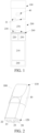
FIG. 1 is a schematic structural diagram of an electronic atomization device according to an embodiment of this application; -
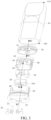
FIG. 2 is a schematic structural diagram of an atomizer inFIG. 1 according to an embodiment; -
FIG. 3 is a schematic exploded diagram of the atomizer inFIG. 2 from a perspective; -
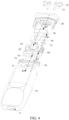
FIG. 4 is a schematic exploded diagram of the atomizer inFIG. 2 from another perspective; -
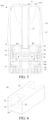
FIG. 5 is a schematic cross-sectional view along the longitudinal direction of the atomizer inFIG. 2 ; -
FIG. 6 is a schematic structural diagram of a porous body inFIG. 5 from another perspective; -
FIG. 7 is a schematic diagram of the seal element and the porous body before assembly inFIG. 5 ; -
FIG. 8 is a schematic structural diagram of the seal element inFIG. 7 from another perspective; -
FIG. 9 is a schematic cross-sectional view of the seal element and the porous body after assembly inFIG. 8 ; -
FIG. 10 is a schematic structural diagram of a seal element according to another embodiment from a perspective; -
FIG. 11 is a schematic cross-sectional view of the seal element and the porous body after assembly inFIG. 10 ; -
FIG. 12 is a schematic structural diagram of a seal element according to still another embodiment from a perspective; -
FIG. 13 is a schematic diagram of a seal element being formed in a holder through double-color injection according to an embodiment; -
FIG. 14 is a schematic structural diagram of a seal element according to still another embodiment; -
FIG. 15 is a schematic structural diagram of still another seal element sealing cooperating with a porous body; -
FIG. 16 is a schematic structural diagram of still another seal element sealing cooperating with a porous body; and -
FIG. 17 is a schematic structural diagram of still another seal element sealing cooperating with a porous body. - For ease of understanding of this application, this application is described in further detail below with reference to the accompanying drawings and specific implementations.
- An embodiment of this application provides an electronic atomization device. Referring to
FIG. 1 , the electronic atomization device includes: anatomizer 100, configured to store a liquid substrate and atomize the liquid substrate to generate an aerosol; and apower supply mechanism 200, configured to supply power to theatomizer 100. - In an optional implementation, as shown in
FIG. 1 , thepower supply mechanism 200 includes: a receivingcavity 270, arranged at an end along a length direction, and configured to receive and accommodate at least a part of theatomizer 100; and a firstelectrical contact 230, at least partially exposed on a surface of the receivingcavity 270, and configured to be electrically connected to theatomizer 100 to supply power to theatomizer 100 when at least a part of theatomizer 100 is received and accommodated in thepower supply mechanism 200. - According to a preferred implementation shown in
FIG. 1 , an end portion of theatomizer 100 opposite to thepower supply mechanism 200 along the length direction is provided with a secondelectrical contact 21, so that when at least a part of theatomizer 100 is received in the receivingcavity 270, the secondelectrical contact 21 forms conductivity through being in contact with and abutting against the firstelectrical contact 230. - A
seal element 260 is arranged inside thepower supply mechanism 200, and at least a part of an internal space of thepower supply mechanism 200 is separated through theseal element 260 to form the receivingcavity 270. In the preferred implementation shown inFIG. 1 , theseal element 260 is configured to extend along a cross section direction of thepower supply mechanism 200, and is preferably prepared by a flexible material such as silica gel, so as to prevent the liquid substrate seeping from theatomizer 100 to the receivingcavity 270 from flowing to acontroller 220, asensor 250, and other components inside thepower supply mechanism 200. - In the preferred implementation shown in
FIG. 1 , thepower supply mechanism 200 further includes: abattery cell 210, located at another end facing away from the receivingcavity 270 along the length direction, and configured to supply power; and acontroller 220, arranged between thebattery cell 210 and an accommodating cavity, and operably guiding a current between thebattery cell 210 and the firstelectrical contact 230. - In use, the
power supply mechanism 200 includes asensor 250, configured to sense an inhalation flow generated by theatomizer 100 during inhalation, so that thecontroller 220 controls thebattery cell 210 to output the current to theatomizer 100 according to a detection signal of thesensor 250. - Further, in the preferred implementation shown in
FIG. 1 , a charginginterface 240 is arranged on another end of thepower supply mechanism 200 facing away from the receivingcavity 270, and is configured to supply power to thebattery cell 210. - The embodiments in
FIG. 2 to FIG. 5 are schematic structural diagrams of an embodiment of theatomizer 100 inFIG. 1 . Theatomizer 100 includes:
amain housing 10. According toFIG. 2 andFIG. 3 , themain housing 10 is generally in a flat cylindrical shape; and themain housing 10 has anear end 110 and afar end 120 opposite to each other along the length direction. According to the requirements of common use, thenear end 110 is configured as an end for the user to inhale the aerosol, and a suction nozzle A for the user to inhale is arranged on thenear end 110; and thefar end 120 is used as an end combined with thepower supply mechanism 200, and thefar end 120 of themain housing 10 is an opening on which adetachable end cap 20 is installed. The opening structure is configured to install necessary functional components inside themain housing 10. - Further, in a specific implementation shown in
FIG. 2 to FIG. 4 , the secondelectrical contact 21 is penetrated into theatomizer 100 from a surface of theend cap 20, so that at least a part of the secondelectrical contact 21 is exposed outside theatomizer 100, so as to form conductivity through being in contact with the firstelectrical contact 230. In addition, theend cap 20 is further provided with afirst air inlet 23, configured to supply external air into theatomizer 100 during inhalation. - According to
FIG. 2 to FIG. 4 , theatomizer 100 further includes amagnetic element 22, penetrating into theatomizer 100 from the surface of theend cap 20, and configured to stabilize theatomizer 100 in the receivingcavity 270 through magnetic adsorption when theatomizer 100 is received in the receivingcavity 270. - Further referring to
FIG. 3 to FIG. 5 , themain housing 10 is internally provided with aliquid storage cavity 12 for storing the liquid substrate, and an atomization assembly for absorbing the liquid substrate from theliquid storage cavity 12, and heating and atomizing the liquid substrate. The atomization assembly generally includes a capillary liquid guide element for absorbing the liquid substrate, and a heating element combined with the liquid guide element. The heating element heats at least a part of the liquid substrate in the liquid guide element to generate the aerosol during power on. In an optional implementation, the liquid guide element includes flexible fibers such as cotton fibers, non-woven fabrics, and glass fiber ropes, or includes porous materials with a microporous structure, such as porous ceramics. The heating element can be combined onto the liquid guide element or wound on the liquid guide element through printing, deposition, sintering, physical assembly, or the like. - Further, in a preferred implementation shown in
FIG. 3 to FIG. 5 , the atomization assembly includes: aporous body 30, configured to absorb and transfer the liquid substrate; and aheating element 40, configured to heat and atomize the liquid substrate absorbed by theporous body 30. Specifically,
in the schematic structural cross-sectional view shown inFIG. 5 , themain housing 10 is internally provided with a fluegas transmission pipe 11 arranged along an axial direction; and themain housing 10 is further internally provided with aliquid storage cavity 12 configured to store the liquid substrate. In the implementation, at least a part of the fluegas transmission pipe 11 extends in theliquid storage cavity 12, and theliquid storage cavity 12 is formed by the space between an outer wall of the fluegas transmission pipe 11 and an inner wall of themain housing 10. A first end of the fluegas transmission pipe 11 opposite to thenear end 110 is in communication with the suction nozzle A, and a second end opposite to thefar end 120 is in airflow connection with anatomization chamber 340 formed by defining between anatomization surface 310 of theporous body 30 and theend cap 20, so as to transmit the aerosol generated by the atomized liquid substrate in theheating element 40 and released to theatomization chamber 340 to the suction nozzle A for inhalation. - Referring to the structure of the
porous body 30 shown inFIG. 3 ,FIG. 4 , andFIG. 5 , the shape of theporous body 30 is configured to be, but not limited to, generally a block structure in the embodiment. According to a preferred design of this embodiment, theporous body 30 includes theatomization surface 310 which is arched in shape and faces theend cap 20 along the axial direction of themain housing 10. In use, a side of theporous body 30 facing away from theatomization surface 310 is in fluid communication with theliquid storage cavity 12, so as to absorb the liquid substrate, then the microporous structure inside theporous body 30 transmits the liquid substrate to theatomization surface 310 to be heated and atomized to form the aerosol, and the formed aerosol is released or escaping from theatomization surface 310. - Certainly, the
heating element 40 is formed on theatomization surface 310; and after assembly, the secondelectrical contact 21 abuts against theheating element 40, so as to supply power to theheating element 40. - Further, referring to
FIG. 3 to FIG. 5 , in order to assist in the installation and fixation of theporous body 30 and the sealing of theliquid storage cavity 12, themain housing 10 is further provided with aflexible seal element 50, aholder 60 and a flexiblefirst seal element 70, which not only seals an opening of theliquid storage cavity 12, but also fixes and holds theporous body 30 inside. - For the specific structure and shape, the
flexible seal element 50 is generally in a hollow cylinder shape. The inner hollow is configured to accommodate theporous body 30, and is sleeved outside theporous body 30 in a close fitting manner. - The
rigid holder 60 holds theporous body 30 sleeved with theflexible seal element 50. In some embodiments, theholder 60 may generally have an annular shape with an open lower end. A holdingspace 64 is configured to accommodate and hold theflexible seal element 50 and theporous body 30. On one hand, theflexible seal element 50 can seal a gap between theporous body 30 and theholder 60 to prevent the liquid substrate from seeping out of the gap between them; and on the other hand, theflexible seal element 50 is located between theporous body 30 and theholder 60, which is advantageous for theporous body 30 to be stably accommodated in theholder 60 to avoid from loosening. - The flexible
first seal element 70 is arranged between theliquid storage cavity 12 and theholder 60, and the shape of the flexiblefirst seal element 70 is adapted to the cross section of the inner contour of themain housing 10, so as to seal theliquid storage cavity 12 and prevent the liquid substrate from leaking out of theliquid storage cavity 12. Further, in order to prevent the shrinkage and deformation of thefirst seal element 70 made of the flexible materials from affecting the tightness of the sealing, theholder 60 is accommodated in the flexiblefirst seal element 70 to provide support for thefirst seal element 70. - After installation, in order to ensure the smooth transmission of the liquid substrate and the output of the aerosol, the flexible
first seal element 70 is provided with a firstliquid guide hole 71 for the liquid substrate to flow through, theholder 60 is correspondingly provided with a secondliquid guide hole 61, and theflexible seal element 50 is provided with aliquid guide hole 51. In use, the liquid substrate in theliquid storage cavity 12 flows to theporous body 30 held in theflexible seal element 50 via the firstliquid guide hole 71, the secondliquid guide hole 61, and theliquid guide hole 51 successively as shown by arrow R1 inFIG. 4 andFIG. 5 , then the liquid substrate is absorbed and transferred to theatomization surface 310 for atomization, and the generated aerosol is released into theatomization chamber 340 defined between theatomization surface 310 and theend cap 20. - On an aerosol output path during the inhalation process, referring to
FIG. 3 to FIG. 6 , the flexiblefirst seal element 70 is provided with afirst insertion hole 72 for a lower end of the fluegas transmission pipe 11 to plug in, theholder 60 is correspondingly provided with asecond insertion hole 62, and an opposite side of theholder 60 to themain housing 10 is provided with anaerosol output channel 63 through which theatomization surface 310 is in airflow communication with thesecond insertion hole 62. A complete inhalation flow path after installation is shown by arrow R2 inFIG. 4 . The external air enters theatomization chamber 340 via thefirst air inlet 23 on theend cap 20, then carries the generated aerosol to flow from theaerosol output channel 63 to thesecond insertion hole 62, and then outputs to the fluegas transmission pipe 11 via thefirst insertion hole 72. - Referring to the preferred implementation shown in
FIG. 6 , theporous body 30 is arched in shape and has afirst side portion 31 and asecond side portion 32 opposite to each other along a thickness direction, and abase part 34 extending between thefirst side portion 31 and thesecond side portion 32; and a lower surface of thebase part 34 is configured as anatomization surface 310. In addition, thefirst side portion 31 and thesecond side portion 32 extend along a length direction of theporous body 30. Accordingly, aliquid channel 33 extending along the length direction of theporous body 30 is defined among thefirst side portion 31, thesecond side portion 32, and thebase part 34, and the liquid substrate flowing via the firstliquid guide hole 71, the secondliquid guide hole 61, and theliquid guide hole 51 is received and absorbed through theliquid channel 33. - Further, according to
FIG. 6 and FIG. 5 , theporous body 30 further includes asupport part 35 extending along a cross section direction of theatomizer 100 between thefirst side portion 31 and thesecond side portion 32. Theseal element 50 is generally in a hollow cylinder shape, and the inner hollow is an accommodating cavity configured to accommodate and wrap theporous body 30, so as to be wrapped outside theporous body 30 after assembly. An inner surface of theseal element 50 is provided with severalconvex ribs 52 configured to improve the sealing effect after installation. Theseconvex ribs 52 are mainly configured to seal the gap between theholder 60 and theporous body 30 to prevent leakage from the gap between theholder 60 and theporous body 30 in the process of liquid transmission. Therefore, in the implementation, the severalconvex ribs 52 form into a closed ring shape together, which completely surrounds or wraps the liquid transmission channel, so as to achieve a better sealing effect. - The structure of the
seal element 50 is shown inFIG. 7 and FIG. 8 . Theseal element 50 is in a square cylinder shape with an open lower end. An inner wall of the accommodating cavity formed by theseal element 50 to accommodate and surround theporous body 30 include: - a first
inner side wall 510 and a secondinner side wall 520 opposite to each other along the length direction; - a third
inner side wall 530 and a fourthinner side wall 540 opposite to each other along a width direction; and - an inner
upper wall 550, adjacent to or wrapping asupport part 35 of theporous body 30, and supported by thesupport part 35 of theporous body 30 after assembly. - The
convex ribs 52 on an inner wall of theseal element 50 include: - a
first section 521, located on the firstinner side wall 510 and extending along a width direction of theseal element 50, where the first section is opposite to thebase part 34 of theporous body 30, and abuts against thebase part 34 of theporous body 30 to form an interference fit to seal a gap between them after assembly; - a
second section 522, located on the firstinner side wall 510 and extending along a longitudinal direction of theseal element 50, where the second section is opposite to an end surface on one side of thefirst side portion 31 of theporous body 30 along the length direction, and abuts against thefirst side portion 31 of theporous body 30 to form an interference fit after assembly; - a
third section 523, located on the innerupper wall 550 and extending along a length direction of theseal element 50, where the third section is opposite to thefirst side portion 31 of theporous body 30, and abuts against thefirst side portion 31 of theporous body 30 to form an interference fit after assembly; - a
fourth section 524, located on the secondinner side wall 520 and extending along the longitudinal direction of theseal element 50, where the second section is opposite to an end surface on one side of thefirst side portion 31 of theporous body 30 along the length direction, and abuts against thefirst side portion 31 of theporous body 30 to form an interference fit after assembly; - a
fifth section 525, located on the secondinner side wall 520 and extending along the width direction of theseal element 50, where the fifth section is opposite to thebase part 34 of theporous body 30, and abuts against thebase part 34 of theporous body 30 to form an interference fit to seal a gap between them after assembly; - a
sixth section 526, located on the secondinner side wall 520 and extending along the longitudinal direction of theseal element 50, where the sixth section is opposite to an end surface on one side of thesecond side portion 32 of theporous body 30 along the length direction, and abuts against thesecond side portion 32 of theporous body 30 to form an interference fit after assembly; - a
seventh section 527, located on the innerupper wall 550 and extending along the length direction of theseal element 50, where the seventh section is opposite to thesecond side portion 32 of theporous body 30, and abuts against thesecond side portion 32 of theporous body 30 to form an interference fit after assembly; and - an
eighth section 528, located on the firstinner side wall 510 and extending along the longitudinal direction of theseal element 50, where the eighth section is opposite to an end surface of one side of thesecond side portion 32 of theporous body 30 along the length direction, and abuts against thesecond side portion 32 of theporous body 30 to form an interference fit after assembly. - Further, according to
FIG. 7 and FIG. 8 , theconvex ribs 52 have eight sections in total, and are connected to form a closed shape by connecting end to end successively. Certainly, the above closed ring formed by theconvex ribs 52 is a non-planar closed ring having a span along a length direction of theatomizer 100. - In the implementation, the
liquid guide hole 51 is located in the closed ring formed by theconvex ribs 52. - Further, in a preferred implementation shown in
FIG. 8 andFIG. 9 , the innerupper wall 550 of theseal element 50 is provided withpositioning cantilevers 53 on two sides along the length direction. InFIG. 8 , the positioning cantilevers 53 extend longitudinally. In the assembly with theporous body 30, the twopositioning cantilevers 53 respectively clamp or fit thesupport part 35 of theporous body 30 from two sides, so as to facilitate the auxiliary guidance and positioning during their assembly. -
FIG. 10 and FIG. 11 show schematic structural diagrams of aseal element 50a according to another embodiment. As shown inFIG. 10 ,convex ribs 52a on an inner wall of theseal element 50a include:
afirst section 521a, asecond section 522a, athird section 523a, afourth section 524a, afifth section 525a, and asixth section 526a connected end to end successively to form a first closed ring surrounding aliquid guide hole 51a; and aseventh section 5210a, aneighth section 5220a, aninth section 5230a, atenth section 5240a, aneleventh section 5250a, and atwelfth section 5260a connected end to end successively to form a second closed ring surrounding anotherliquid guide hole 52a. - The first closed ring is close to a first
inner side wall 510a, and the second closed ring is close to a secondinner side wall 520a. - After the
seal element 50a is assembled with theporous body 30, thefourth section 524a and thetenth section 5240a both abut against or fit thesupport part 35 of theporous body 30 to form an interference fit. Thefourth section 524a and thetenth section 5240a are respectively arranged on two sides of the innerupper wall 550a along a length direction of theseal element 50a. - Compared with the structure of the
seal element 50 inFIG. 8 ,FIG. 12 shows a schematic structural diagram of aseal element 50b in another embodiment;convex ribs 52b thereof have aninth section 529b extending along the width direction between athird section 523b and aseventh section 527b, and theninth section 529b divides the closed ring formed through successively connecting afirst section 521b to aneighth section 528b into two annular parts respectively surrounding aliquid guide hole 51b. - According to the above, each section of the
convex ribs 52/52a/52b after assembly can be supported by theporous body 30, so as to stably form an interference fit to seal gaps between the convex ribs and between theporous body 30 and theholder 60. - Further, referring to
FIG. 13 , theseal element 50 made of silica gel and theholder 60 made of organic polymer plastic are obtained by injection molding together in the mold through premolding, such as double-color injection molding; and theseal element 50 is molded and combined into an inner wall of the holdingspace 64 of theholder 60 directly through premolding, such as a double-color injection molding process. - Further,
FIG. 14 shows a schematic structural diagram of aseal element 50c in another embodiment. The inner wall of theseal element 50c is formed with aconvex rib 52c; In addition, an outer surface of theseal element 50c is further provided with a secondconvex rib 54c. After assembly, the secondconvex rib 54c abuts against an inner surface of the holdingspace 64 of theholder 60, so as to seal the gap between them. - It can be learned from the implementation shown in
FIG. 14 that the secondconvex rib 54c is generally the same shape as theconvex rib 52c on the inner wall, and is arranged at a position opposite to theconvex rib 52c on the outer surface. - Further, in an embodiment shown in
FIG. 15 , a structure of aporous body 30c and theseal element 50c with better sealing effect to prevent the leakage of the liquid substrate between joint gaps of various components is proposed. Specifically,
theporous body 30c includes: - a
base part 310c, extending along the cross section direction of theatomizer 100, where an upper surface and a lower surface of thebase part 310c can be respectively used as a liquid absorption surface and theatomization surface 310, the liquid absorption surface and theatomization surface 310 are arranged facing away from each other, and the liquid absorption surface and theatomization surface 310 are arranged along a first direction of theporous body 30c; and - a
first extension arm 320c and asecond extension arm 330c, formed by extending upward from thebase part 310c along the length direction of theatomizer 100, where the length direction of theatomizer 100 is parallel to a second direction of theporous body 30c. In a preferred implementation shown inFIG. 15 , thefirst extension arm 320c and thesecond extension arm 330c are respectively arranged on the opposite two sides of thebase part 310c along a thickness direction of theatomizer 100, where the thickness direction of theatomizer 100 is parallel to a third direction of theporous body 30c. - Further, in the preferred implementation shown in
FIG. 15 , theporous body 30c further includes asupport part 340c extending along the cross section direction of theatomizer 100 between thefirst extension arm 320c and thesecond extension arm 330c. - The
seal element 50c is generally in a hollow cylinder shape, and is wrapped outside theporous body 30c. - The outer surface of the
seal element 50c is provided with several convex ribs configured to improve the sealing effect after installation. These convex ribs are mainly configured to seal the liquid substrate transmission channel between theholder 60 and theporous body 30c to prevent leakage from the gap between theholder 60 and theporous body 30c in the process of liquid transmission. Therefore, in the implementation, the several convex ribs form into a closed ring shape together, which completely surrounds or wraps the liquid transmission channel, so as to achieve a better sealing effect. The several convex ribs specifically include:
A firstconvex rib 510c, consisting of two sections, where the two sections are respectively arranged on two outer side walls of theseal element 50c along the width direction, and the firstconvex rib 510c extends along a thickness direction in the figure. - In addition, the first
convex rib 510c is corresponding to or coincident with thebase part 310c of theporous body 30c in an assembled position, so that the firstconvex rib 510c can be supported by thebase part 310c, and the firstconvex rib 510c can closely abut against an inner wall of theholder 60. - A second
convex rib 520c, consisting of two sections, where the two sections are respectively arranged on two sides of the surface of an upper wall of theseal element 50c close to the thickness direction, configured to extend along the width direction in the figure, and respectively opposite to thesupport part 340c in position, so that the secondconvex rib 520c can be supported by thesupport part 340c after installation, and the secondconvex rib 520c can closely abut against the inner wall of theholder 60. - A third
convex rib 530c, consisting of four sections, where the four sections are specifically respectively arranged on two outer side walls of theseal element 50c along the thickness direction (in the figure, two sections of the thirdconvex rib 530c on the opposite side are blocked and thus not shown), and a first end along the length direction is connected to the firstconvex rib 510c, and a second end is connected to the secondconvex rib 520c. After installation, the thirdconvex rib 530c is supported by outer side walls of thefirst extension arm 320c and thesecond extension arm 330c, so that the thirdconvex rib 530c can closely abut against the inner wall of theholder 60. - According to the preferred implementation in
FIG. 15 , the thirdconvex rib 530c consists of four sections in total, and the firstconvex rib 510c, the secondconvex rib 520c, and the thirdconvex rib 530c arranged on theseal element 50c are connected to form into a closed shape through connection. Certainly, the above closed shape formed by the convex ribs is a non-planar closed ring having a span along the length direction of theatomizer 100. - In addition, according to the preferred implementation in
FIG. 15 , the thirdconvex rib 530c is arranged obliquely outward along the width direction. - Further, in the preferred implementation shown in
FIG. 15 , theseal element 50c is provided with a throughhole 540c located between the two opposite sections of the secondconvex rib 520c. In the implementation, the throughhole 540c is opposite to thesecond insertion hole 62 on therigid holder 60, so that condensate of the aerosol transmitted in the fluegas transmission pipe 11 can fall downward and then be received and absorbed by thesupport part 340c through the throughhole 540c. -
FIG. 16 is a schematic diagram in which aseal element 50d is provided with convex ribs to improve the sealing effect according to still another embodiment. In this embodiment, there are two convex ribs that are separated from each other and each is in a closed ring shape. Specifically,
a first closed ring is composed of the firstconvex rib 510d arranged on the side wall in a width direction, the secondconvex rib 520d arranged on a top part, and two sections of the thirdconvex rib 530d located on two side walls in the thickness direction. - Similarly, another ring, that is, a second closed ring is further included composed of a fourth
convex rib 511d, a fifthconvex rib 521d, and two sections of sixthconvex rib 531d. - Certainly, the closed rings formed by the several convex ribs are separated from each other and symmetrically arranged on the
seal element 50d along the width direction and the thickness direction. - Regarding the convex rib structure arrangement of the preferred embodiment shown in
FIG. 16 , two symmetrical closed rings respectively surround twofluid communication ports 51d, so as to prevent leakage from the gap between theholder 60 and theporous body 30c during the transmission of the liquid substrate. - In addition, according to the preferred implementation shown in
FIG. 16 , theseal element 50d is provided with achannel part 540d, formed by a depression and used for outputting the aerosol during the inhalation process, on two sides along the thickness direction, to form a part of an airflow path R2 during the inhalation process. The corresponding thirdconvex rib 530d and the sixthconvex rib 531d are respectively arranged on two sides of thechannel part 540d. - Further, according to the preferred implementations shown in
FIG. 15 and FIG. 16 , the extension path of the formed closed annular convex ribs completely passes through the entire outer surface of theseal element 50c/50d, that is, the left and right outer side walls of theseal element 50c/50d along the width direction, the front and rear outer side walls along the thickness direction, and the outer surface of the upper wall all have a part of the closed ring extended thereon. - In still another optional implementation shown in
FIG. 17 , in the two closed annular convex ribs of aseal element 50e, a secondconvex rib 520e consists of two parts at a certain angle; and a corresponding fifthconvex rib 521e similarly has two parts at a certain angle. - Certainly, in the
seal element 50e shown inFIG. 17 , the secondconvex rib 520e and the fifthconvex rib 521e are both supported by thesupport part 340c. - In addition, in the
seal element 50e shown inFIG. 17 , in the embodiment, two closed rings formed by connecting several convex ribs successively inFIG. 17 can be connected. - In addition, in the preferred implementation shown in
FIG. 15 to FIG. 17 above, the several convex ribs are symmetrically arranged along the thickness direction or the width direction of theatomizer 100. - In the above e-cigarette atomizer, a corresponding structure adapted to the
porous body 30c with thesupport part 340c is used, and the convex ribs corresponding to each part of theporous body 30c are arranged on theseal element 50c/50d/50e, so that after assembly, theporous body 30c and therigid holder 60 can completely closely abut against each other and the liquid guide channel can be separated, thereby improving the sealing effect. - It is to be noted that, the specification of this application and the accompanying drawings thereof illustrate preferred embodiments of this application, but this application is not limited to the embodiments described in this specification. Further, the foregoing technical features can further be combined to form various embodiments not listed above, and all such embodiments shall be construed as falling within the scope of the present invention. Further, persons of ordinary skill in the art may make improvements and variations according to the above descriptions, and such improvements and variations shall all fall within the protection scope of the appended claims of this application.
Claims (19)
- An atomizer, comprising:a liquid storage cavity, configured to store a liquid substrate;a porous body, being in fluid communication with the liquid storage cavity to receive the liquid substrate;a heating element, combined with the porous body, and configured to heat at least a part of the liquid substrate in the porous body to generate an aerosol;a holder, configured to hold the porous body; anda seal element, arranged between the holder and the porous body, and configured to seal a gap between the holder and the porous body, wherein the seal element comprises a plurality of side walls surrounding the porous body along a circumferential direction of the porous body and an upper end wall, whereinthe seal element comprises convex ribs extending on outer surfaces of the plurality of side walls and the upper end wall or on inner surfaces of the plurality of side walls and the upper end wall, and the convex ribs are connected into at least one closed ring.
- The atomizer according to claim 1, wherein a liquid guide hole is arranged on the seal element, and the porous body is in fluid communication with the liquid storage cavity through the liquid guide hole; and the liquid guide hole is located in the at least one closed ring.
- The atomizer according to claim 1 or 2, wherein the convex ribs are symmetrically arranged along a length direction and/or a width direction of the seal element.
- The atomizer according to claim 1 or 2, wherein the convex ribs comprise several sections, and the several sections are connected end to end successively to form the at least one closed ring.
- The atomizer according to claim 4, wherein any two adjacent sections of the several sections of the convex ribs are basically perpendicular to each other.
- The atomizer according to claim 1 or 2, wherein the porous body has a liquid channel that runs through the porous body along a length direction, and is in fluid communication with the liquid storage cavity through the liquid channel; and the convex ribs avoid the liquid channel.
- The atomizer according to claim 1 or 2, wherein the plurality of side walls comprise at least a first side wall and a second side wall opposite to each other along the length direction of the seal element, and a third side wall and a fourth side wall opposite to each other along the width direction of the seal element.
- The atomizer according to claim 7, wherein the convex ribs comprise:a first convex rib, arranged on the outer surface(s) of the first side wall or/and the second side wall;a second convex rib, arranged on the outer surface of the upper end wall;a third convex rib, arranged on the outer surface of the third side wall; anda fourth convex rib, arranged on the outer surface of the fourth side wall, whereinthe first convex rib, the second convex rib, the third convex rib, and the fourth convex rib are connected into the at least one closed ring.
- The atomizer according to claim 8, whereinthe first convex rib comprises a first section arranged on the first side wall and a second section arranged on the second side wall;the second convex rib comprises a third section and a fourth section opposite to each other along the width direction of the seal element, wherein the third section is arranged close to the third side wall, and the fourth section is arranged close to the fourth side wall;the third convex rib comprises a fifth section and a sixth section arranged opposite to each other along the length direction of the seal element, wherein the fifth section is arranged close to the first side wall, and the sixth section is arranged close to the second side wall;the fourth convex rib comprises a seventh section and an eighth section arranged opposite to each other along the length direction of the seal element, wherein the seventh section is arranged close to the first side wall, and the eighth section is arranged close to the second side wall; andthe first section, the fifth section, the third section, the sixth section, the second section, the eighth section, the fourth section, and the seventh section are connected end to end successively to form a closed ring.
- The atomizer according to claim 8, whereinthe first convex rib comprises a first section arranged on the first side wall and a second section arranged on the second side wall;the second convex rib comprises a third section and a fourth section opposite to each other along the width direction of the seal element, wherein the third section is arranged close to the first side wall, and the fourth section is arranged close to the second side wall;the third convex rib comprises a fifth section and a sixth section arranged opposite to each other along the length direction of the seal element, wherein the fifth section is arranged close to the first side wall, and the sixth section is arranged close to the second side wall;the fourth convex rib comprises a seventh section and an eighth section arranged opposite to each other along the length direction of the seal element, wherein the seventh section is arranged close to the first side wall, and the eighth section is arranged close to the second side wall; andthe first section, the fifth section, the third section, and the seventh section are connected end to end successively to form a first closed ring, and the second section, the sixth section, the fourth section, and the eighth section are connected end to end successively to form a second closed ring.
- The electronic atomization device atomizer according to claim 10, further comprising a flue gas output channel, wherein the upper end wall is provided with a through hole opposite to the flue gas output channel; and
the third section and the fourth section are arranged at two sides of the through hole respectively. - The atomizer according to claim 10, wherein the third section and/or the fourth section extend(s) along the width direction of the seal element.
- The atomizer according to claim 8, wherein at least a part of the third convex rib and/or the fourth convex rib is arranged obliquely.
- The atomizer according to claim 8, wherein the porous body has a first direction, a second direction perpendicular to the first direction, and a third direction perpendicular to the first direction and the second direction; the porous body comprises a base part, and the base part is arranged parallel to the second direction and the third direction, and is provided with a liquid absorption surface and an atomization surface facing away from each other along the first direction; the porous body further comprises a first extension arm and a second extension arm extending from the base part away from the atomization surface, and a support part extending between the first extension arm and the second extension arm; and the first extension arm and the second extension arm are parallel to the second direction, and are arranged opposite to each other along the third direction.
- The atomizer according to claim 14, wherein the first convex rib is opposite to at least a part of the base part;and/or the third convex rib is opposite to at least a part of the first extension arm;and/or the fourth convex rib is opposite to at least a part of the second extension arm.
- The atomizer according to claim 7, wherein the convex ribs comprise:a first section, located on the inner surface of the first side wall and extending along the width direction of the seal element;a second section, located on the inner surface of the first side wall and close to the third side wall;a third section, extending on the inner surface of the upper end wall along the length direction of the seal element and close to the third side wall;a fourth section, extending on the inner surface of the upper end wall along the width direction of the seal element;a fifth section, extending on the inner surface of the upper end wall along the length direction of the seal element and close to the fourth side wall; anda sixth section, located on the inner surface of the first side wall and close to the fourth side wall.
- The atomizer according to claim 7, wherein the convex ribs comprise:a first section, located on the inner surface of the first side wall and extending along the width direction of the seal element;a second section, located on the inner surface of the first side wall and close to the third side wall;a third section, extending on the inner surface of the upper end wall along the length direction of the seal element and close to the third side wall;a fourth section, located on the inner surface of the second side wall and close to the third side wall;a fifth section, located on the inner surface of the second side wall and extending along the width direction of the seal element;a sixth section, located on the inner surface of the second side wall and close to the fourth side wall;a seventh section, extending on the inner surface of the upper end wall along the length direction of the seal element and close to the fourth side wall; andan eighth section, located on the inner surface of the first side wall and close to the fourth side wall.
- An electronic atomization device, comprising an atomization device, and a power supply device configured to supply power to the atomization device, wherein the atomization device comprises the atomizer according to any one of claims 1 to 17.
- A seal element for an atomizer, the seal element comprising a plurality of side walls and an upper end wall, wherein the seal element comprises several convex ribs extending on outer surfaces of the plurality of side walls and the upper end wall or on inner surfaces of the plurality of side walls and the upper end wall, and the several convex ribs are connected into at least one closed ring.
Applications Claiming Priority (3)
| Application Number | Priority Date | Filing Date | Title |
|---|---|---|---|
| CN202010545939.1A CN113796579A (en) | 2020-06-16 | 2020-06-16 | Electronic cigarette atomizer and electronic cigarette |
| CN202120651505.XU CN215347025U (en) | 2021-03-31 | 2021-03-31 | Atomizer, electronic atomization device and sealing element for atomizer |
| PCT/CN2021/100373 WO2021254395A1 (en) | 2020-06-16 | 2021-06-16 | Atomizer, electronic atomization device, and sealing element for atomizer |
Publications (3)
| Publication Number | Publication Date |
|---|---|
| EP4166014A1 true EP4166014A1 (en) | 2023-04-19 |
| EP4166014A4 EP4166014A4 (en) | 2023-12-06 |
| EP4166014B1 EP4166014B1 (en) | 2025-12-24 |
Family
ID=79268513
Family Applications (1)
| Application Number | Title | Priority Date | Filing Date |
|---|---|---|---|
| EP21826222.8A Active EP4166014B1 (en) | 2020-06-16 | 2021-06-16 | Atomizer with sealing element |
Country Status (3)
| Country | Link |
|---|---|
| US (1) | US20230240364A1 (en) |
| EP (1) | EP4166014B1 (en) |
| WO (1) | WO2021254395A1 (en) |
Cited By (1)
| Publication number | Priority date | Publication date | Assignee | Title |
|---|---|---|---|---|
| EP4285752A4 (en) * | 2021-01-27 | 2024-08-14 | Shenzhen First Union Technology Co., Ltd. | ATOMIZATION CORE ASSEMBLY, ATOMIZER AND ELECTRONIC ATOMIZATION DEVICE |
Families Citing this family (2)
| Publication number | Priority date | Publication date | Assignee | Title |
|---|---|---|---|---|
| KR102467836B1 (en) * | 2018-10-30 | 2022-11-16 | 주식회사 케이티앤지 | Aerosol-generating article and aerosol-generating device comprising theh same |
| CN121013658A (en) * | 2023-03-29 | 2025-11-25 | 菲利普莫里斯生产公司 | Cylinder for aerosol generation systems with improved sealing elements |
Family Cites Families (18)
| Publication number | Priority date | Publication date | Assignee | Title |
|---|---|---|---|---|
| US10306929B2 (en) * | 2015-04-24 | 2019-06-04 | Shenzhen Smoore Technology Limited | Electronic cigarette and atomizer device thereof |
| WO2017068094A1 (en) * | 2015-10-22 | 2017-04-27 | Philip Morris Products S.A. | Aerosol-generating article, aerosol-generating system and method for manufacturing an aerosol-generating article |
| GB201605100D0 (en) * | 2016-03-24 | 2016-05-11 | Nicoventures Holdings Ltd | Vapour provision system |
| CN206603261U (en) * | 2017-04-01 | 2017-11-03 | 深圳市优维尔科技有限公司 | An anti-pressure oil sealing mechanism of an electronic atomizer and its electronic atomizer |
| CN108308711B (en) * | 2018-01-15 | 2023-10-10 | 惠州市新泓威科技有限公司 | Electronic cigarette atomizer |
| WO2019232086A1 (en) * | 2018-05-29 | 2019-12-05 | Pax Labs, Inc. | Vaporizer device with cartridge |
| EP3847914B1 (en) * | 2018-09-05 | 2025-10-29 | Shenzhen Smoore Technology Limited | Atomizer and electronic atomization device |
| CN109330028B (en) * | 2018-10-31 | 2021-07-06 | 深圳麦克韦尔科技有限公司 | Electronic cigarette atomizer, assembling method thereof and electronic cigarette |
| CN109393570A (en) * | 2018-11-12 | 2019-03-01 | 安克创新科技股份有限公司 | Atomising device and electronic cigarette |
| CN210726699U (en) * | 2019-04-16 | 2020-06-12 | 常州市派腾电子技术服务有限公司 | Heating element, atomizing head, atomizer and electronic cigarette |
| CN210203316U (en) * | 2019-05-07 | 2020-03-31 | 深圳市合元科技有限公司 | Cartridges and Electronic Cigarettes |
| CN210203317U (en) * | 2019-05-07 | 2020-03-31 | 深圳市合元科技有限公司 | Atomizers and Electronic Cigarettes |
| CN111904038A (en) * | 2019-05-09 | 2020-11-10 | 常州市派腾电子技术服务有限公司 | Cartridges and Electronic Cigarettes |
| CN210611013U (en) * | 2019-06-28 | 2020-05-26 | 深圳市合元科技有限公司 | Electronic cigarette atomizer and electronic cigarette |
| CN110623308B (en) * | 2019-09-29 | 2025-07-08 | 深圳麦克韦尔科技有限公司 | Electronic atomizing device and atomizer thereof |
| CN212590252U (en) * | 2020-06-16 | 2021-02-26 | 深圳市合元科技有限公司 | Electronic cigarette atomizer and electronic cigarette |
| CN212852491U (en) * | 2020-06-16 | 2021-04-02 | 深圳市合元科技有限公司 | Electronic Cigarettes and Electronic Cigarettes |
| CN213819836U (en) * | 2020-10-21 | 2021-07-30 | 深圳市合元科技有限公司 | Atomizers and Electronic Atomizers |
-
2021
- 2021-06-16 US US18/011,153 patent/US20230240364A1/en active Pending
- 2021-06-16 WO PCT/CN2021/100373 patent/WO2021254395A1/en not_active Ceased
- 2021-06-16 EP EP21826222.8A patent/EP4166014B1/en active Active
Cited By (1)
| Publication number | Priority date | Publication date | Assignee | Title |
|---|---|---|---|---|
| EP4285752A4 (en) * | 2021-01-27 | 2024-08-14 | Shenzhen First Union Technology Co., Ltd. | ATOMIZATION CORE ASSEMBLY, ATOMIZER AND ELECTRONIC ATOMIZATION DEVICE |
Also Published As
| Publication number | Publication date |
|---|---|
| US20230240364A1 (en) | 2023-08-03 |
| EP4166014A4 (en) | 2023-12-06 |
| WO2021254395A1 (en) | 2021-12-23 |
| EP4166014B1 (en) | 2025-12-24 |
Similar Documents
| Publication | Publication Date | Title |
|---|---|---|
| EP4166014B1 (en) | Atomizer with sealing element | |
| US20240148069A1 (en) | Atomizer and electronic atomizing device | |
| US20250098773A1 (en) | Vaporizer and electronic vaporization device | |
| CN213819836U (en) | Atomizers and Electronic Atomizers | |
| WO2015143662A1 (en) | Electronic cigarette | |
| CN214127021U (en) | Electronic cigarette cartridges and electronic cigarettes | |
| CN215684777U (en) | Atomizer and electronic atomization device | |
| EP4316277A1 (en) | Atomizer, electronic atomization device, and sealing element for atomizer | |
| US20250113867A1 (en) | Atomizer and electronic atomization device | |
| US20250134170A1 (en) | Electronic atomization device and support for electronic atomization device | |
| CN216416032U (en) | Atomizer, electronic atomization device and atomization assembly | |
| CN219982148U (en) | Atomizer and electronic atomization device | |
| CN215347025U (en) | Atomizer, electronic atomization device and sealing element for atomizer | |
| US20240099386A1 (en) | Vaporizer and electronic vaporization device | |
| CN214103213U (en) | Atomizer and electronic cigarette | |
| US20250134174A1 (en) | Atomizer, electronic atomization apparatus, and sealing element for electronic atomization apparatus | |
| CN115474715A (en) | Atomizers and Electronic Atomization Devices | |
| WO2022156718A1 (en) | Atomiser and electronic atomising apparatus | |
| EP4678034A1 (en) | Atomizer and electronic atomization device | |
| CN217826737U (en) | Atomizer, electronic atomization device and sealing element for atomizer | |
| CN219353055U (en) | Atomizer and electronic atomization device | |
| RU2854720C2 (en) | Electronic spraying device (variants) | |
| CN223310676U (en) | Container, atomizer and electronic atomizing device | |
| CN114098154A (en) | Atomizer and electronic cigarette | |
| CN222941785U (en) | Electronic atomization device |
Legal Events
| Date | Code | Title | Description |
|---|---|---|---|
| STAA | Information on the status of an ep patent application or granted ep patent |
Free format text: STATUS: THE INTERNATIONAL PUBLICATION HAS BEEN MADE |
|
| PUAI | Public reference made under article 153(3) epc to a published international application that has entered the european phase |
Free format text: ORIGINAL CODE: 0009012 |
|
| STAA | Information on the status of an ep patent application or granted ep patent |
Free format text: STATUS: REQUEST FOR EXAMINATION WAS MADE |
|
| 17P | Request for examination filed |
Effective date: 20230109 |
|
| AK | Designated contracting states |
Kind code of ref document: A1 Designated state(s): AL AT BE BG CH CY CZ DE DK EE ES FI FR GB GR HR HU IE IS IT LI LT LU LV MC MK MT NL NO PL PT RO RS SE SI SK SM TR |
|
| DAV | Request for validation of the european patent (deleted) | ||
| DAX | Request for extension of the european patent (deleted) | ||
| REG | Reference to a national code |
Ref country code: DE Ref legal event code: R079 Free format text: PREVIOUS MAIN CLASS: A24F0040100000 Ipc: A24F0040400000 Ref document number: 602021045131 Country of ref document: DE |
|
| STAA | Information on the status of an ep patent application or granted ep patent |
Free format text: STATUS: EXAMINATION IS IN PROGRESS |
|
| A4 | Supplementary search report drawn up and despatched |
Effective date: 20231108 |
|
| RIC1 | Information provided on ipc code assigned before grant |
Ipc: A24F 40/42 20200101ALN20231102BHEP Ipc: A24F 40/10 20200101ALN20231102BHEP Ipc: A24F 40/40 20200101AFI20231102BHEP Ipc: A24F 40/44 20200101ALN20231102BHEP |
|
| 17Q | First examination report despatched |
Effective date: 20231120 |
|
| GRAP | Despatch of communication of intention to grant a patent |
Free format text: ORIGINAL CODE: EPIDOSNIGR1 |
|
| STAA | Information on the status of an ep patent application or granted ep patent |
Free format text: STATUS: GRANT OF PATENT IS INTENDED |
|
| RIC1 | Information provided on ipc code assigned before grant |
Ipc: A24F 40/40 20200101AFI20250717BHEP Ipc: A24F 40/10 20200101ALN20250717BHEP Ipc: A24F 40/42 20200101ALN20250717BHEP Ipc: A24F 40/44 20200101ALN20250717BHEP |
|
| RIC1 | Information provided on ipc code assigned before grant |
Ipc: A24F 40/40 20200101AFI20250721BHEP Ipc: A24F 40/10 20200101ALN20250721BHEP Ipc: A24F 40/42 20200101ALN20250721BHEP Ipc: A24F 40/44 20200101ALN20250721BHEP |
|
| INTG | Intention to grant announced |
Effective date: 20250819 |
|
| GRAS | Grant fee paid |
Free format text: ORIGINAL CODE: EPIDOSNIGR3 |
|
| GRAA | (expected) grant |
Free format text: ORIGINAL CODE: 0009210 |
|
| STAA | Information on the status of an ep patent application or granted ep patent |
Free format text: STATUS: THE PATENT HAS BEEN GRANTED |
|
| AK | Designated contracting states |
Kind code of ref document: B1 Designated state(s): AL AT BE BG CH CY CZ DE DK EE ES FI FR GB GR HR HU IE IS IT LI LT LU LV MC MK MT NL NO PL PT RO RS SE SI SK SM TR |
|
| REG | Reference to a national code |
Ref country code: CH Ref legal event code: F10 Free format text: ST27 STATUS EVENT CODE: U-0-0-F10-F00 (AS PROVIDED BY THE NATIONAL OFFICE) Effective date: 20251224 Ref country code: GB Ref legal event code: FG4D |
|
| REG | Reference to a national code |
Ref country code: DE Ref legal event code: R096 Ref document number: 602021045131 Country of ref document: DE |
|
| REG | Reference to a national code |
Ref country code: LT Ref legal event code: MG9D |
|
| PG25 | Lapsed in a contracting state [announced via postgrant information from national office to epo] |
Ref country code: NO Free format text: LAPSE BECAUSE OF FAILURE TO SUBMIT A TRANSLATION OF THE DESCRIPTION OR TO PAY THE FEE WITHIN THE PRESCRIBED TIME-LIMIT Effective date: 20260324 |
|
| PG25 | Lapsed in a contracting state [announced via postgrant information from national office to epo] |
Ref country code: FI Free format text: LAPSE BECAUSE OF FAILURE TO SUBMIT A TRANSLATION OF THE DESCRIPTION OR TO PAY THE FEE WITHIN THE PRESCRIBED TIME-LIMIT Effective date: 20251224 Ref country code: HR Free format text: LAPSE BECAUSE OF FAILURE TO SUBMIT A TRANSLATION OF THE DESCRIPTION OR TO PAY THE FEE WITHIN THE PRESCRIBED TIME-LIMIT Effective date: 20251224 |
|
| PG25 | Lapsed in a contracting state [announced via postgrant information from national office to epo] |
Ref country code: RS Free format text: LAPSE BECAUSE OF FAILURE TO SUBMIT A TRANSLATION OF THE DESCRIPTION OR TO PAY THE FEE WITHIN THE PRESCRIBED TIME-LIMIT Effective date: 20260324 |
|
| PG25 | Lapsed in a contracting state [announced via postgrant information from national office to epo] |
Ref country code: LV Free format text: LAPSE BECAUSE OF FAILURE TO SUBMIT A TRANSLATION OF THE DESCRIPTION OR TO PAY THE FEE WITHIN THE PRESCRIBED TIME-LIMIT Effective date: 20251224 |
|
| REG | Reference to a national code |
Ref country code: NL Ref legal event code: MP Effective date: 20251224 |
|
| PG25 | Lapsed in a contracting state [announced via postgrant information from national office to epo] |
Ref country code: BG Free format text: LAPSE BECAUSE OF FAILURE TO SUBMIT A TRANSLATION OF THE DESCRIPTION OR TO PAY THE FEE WITHIN THE PRESCRIBED TIME-LIMIT Effective date: 20251224 |