EP4165976A1 - Harverster system and method for automated and semiautomated filling of bins of receiving vehicles - Google Patents
Harverster system and method for automated and semiautomated filling of bins of receiving vehicles Download PDFInfo
- Publication number
- EP4165976A1 EP4165976A1 EP22192784.1A EP22192784A EP4165976A1 EP 4165976 A1 EP4165976 A1 EP 4165976A1 EP 22192784 A EP22192784 A EP 22192784A EP 4165976 A1 EP4165976 A1 EP 4165976A1
- Authority
- EP
- European Patent Office
- Prior art keywords
- receiving vehicle
- harvester
- computing system
- vehicle
- crop material
- Prior art date
- Legal status (The legal status is an assumption and is not a legal conclusion. Google has not performed a legal analysis and makes no representation as to the accuracy of the status listed.)
- Pending
Links
Images






Classifications
-
- A—HUMAN NECESSITIES
- A01—AGRICULTURE; FORESTRY; ANIMAL HUSBANDRY; HUNTING; TRAPPING; FISHING
- A01D—HARVESTING; MOWING
- A01D41/00—Combines, i.e. harvesters or mowers combined with threshing devices
- A01D41/12—Details of combines
- A01D41/1208—Tanks for grain or chaff
- A01D41/1217—Unloading mechanisms
-
- A—HUMAN NECESSITIES
- A01—AGRICULTURE; FORESTRY; ANIMAL HUSBANDRY; HUNTING; TRAPPING; FISHING
- A01D—HARVESTING; MOWING
- A01D41/00—Combines, i.e. harvesters or mowers combined with threshing devices
- A01D41/12—Details of combines
- A01D41/127—Control or measuring arrangements specially adapted for combines
- A01D41/1275—Control or measuring arrangements specially adapted for combines for the level of grain in grain tanks
-
- A—HUMAN NECESSITIES
- A01—AGRICULTURE; FORESTRY; ANIMAL HUSBANDRY; HUNTING; TRAPPING; FISHING
- A01D—HARVESTING; MOWING
- A01D41/00—Combines, i.e. harvesters or mowers combined with threshing devices
- A01D41/12—Details of combines
- A01D41/127—Control or measuring arrangements specially adapted for combines
- A01D41/1278—Control or measuring arrangements specially adapted for combines for automatic steering
-
- A—HUMAN NECESSITIES
- A01—AGRICULTURE; FORESTRY; ANIMAL HUSBANDRY; HUNTING; TRAPPING; FISHING
- A01D—HARVESTING; MOWING
- A01D43/00—Mowers combined with apparatus performing additional operations while mowing
- A01D43/06—Mowers combined with apparatus performing additional operations while mowing with means for collecting, gathering or loading mown material
- A01D43/07—Mowers combined with apparatus performing additional operations while mowing with means for collecting, gathering or loading mown material in or into a trailer
- A01D43/073—Mowers combined with apparatus performing additional operations while mowing with means for collecting, gathering or loading mown material in or into a trailer with controllable discharge spout
-
- A—HUMAN NECESSITIES
- A01—AGRICULTURE; FORESTRY; ANIMAL HUSBANDRY; HUNTING; TRAPPING; FISHING
- A01D—HARVESTING; MOWING
- A01D43/00—Mowers combined with apparatus performing additional operations while mowing
- A01D43/08—Mowers combined with apparatus performing additional operations while mowing with means for cutting up the mown crop, e.g. forage harvesters
- A01D43/086—Mowers combined with apparatus performing additional operations while mowing with means for cutting up the mown crop, e.g. forage harvesters and means for collecting, gathering or loading mown material
- A01D43/087—Mowers combined with apparatus performing additional operations while mowing with means for cutting up the mown crop, e.g. forage harvesters and means for collecting, gathering or loading mown material with controllable discharge spout
Definitions
- the present disclosure relates to systems and methods for detecting crop material path and landing position of a harvester output, and specifically, for example, systems and methods for detecting crop material path and landing position of a forage harvester output. Some embodiments relate to forage harvester systems and methods for automated and semi-automated filing of bins of receiving vehicles.
- Harvesters such as forage harvesters, are used in agricultural production to cut or pick up crops from a field.
- a harvester cuts and picks up forage plants and then dispenses the cut plants to a wagon.
- the harvested forage plants are made into silage.
- Forage harvesters can be implements attached to a tractor or be self-propelled machines.
- Forage harvesters can include a drum or a flywheel with blades that chop and blow the cut crop out of a chute of the harvester into a wagon that is either connected to the harvester or to another vehicle moving the wagon alongside the harvester.
- Forage harvesters can have paddle accelerators to increase the flow of the forage harvester output. Once filled, the wagon can be unloaded and the unloaded silage can be stored. Corn and grass require different types of cutting equipment; thus, there are different heads for each type of crop, and in some examples, the heads are attachable and detachable from the harvester.
- a forage harvester unloads the crop while the harvester is in motion harvesting crop. Unloading the forage harvester while it is in motion requires a receiving vehicle to drive alongside the harvester during the unload operation. This requires the operator driving the receiving vehicle to align a bin of the receiving vehicle with the spout of an unload conveyor of the forage harvester for the duration of the unload operation. Aligning the two vehicles in this manner is laborious for the operator of the receiving vehicle and, in some situations, can be particularly challenging. Some circumstances may limit the operator's visibility, for example, such as where there is excessive dust in the air or at nighttime. Furthermore, if the receiving vehicle has a large or elongated bin it is desirable to shift the position of the bin relative to the spout during the unload operation to evenly fill the grain bin and avoid spilling grain.
- Combine harvesters also process crop but function differently from forage harvesters.
- a combine harvester separates grain from material other than grain (MOG), such as stalks, leaves, and husks; whereas, forage harvesters chop the entire plant-including grain and MOG-into small pieces for storage and feeding to livestock.
- Combine harvesters may store the processed crop onboard the harvester during the harvest operation, rather than transfer the processed crop to a receiving vehicle by blowing the crop material through a discharge chute to the receiving vehicle during the harvesting operation.
- some combine harvesters may also transfer the processed crop to a receiving vehicle by blowing the crop material through a discharge chute to the receiving vehicle during the harvesting operation.
- a receiving vehicle must closely follow such a combine harvester during the entire harvester operation. This presents similar challenges to those discussed herein in relation to the forage harvester.
- Described herein are technologies (such as systems, apparatuses, and methods) that use light detection and ranging (LIDAR) and computer vision to detect a location of a receiving vehicle relative to a forage harvester, fill levels of crop material within the receiving vehicle, and path and landing position of material expelled from the forage harvester and received by a bin of the receiving vehicle.
- the technologies use such information as feedback for operating the harvester or the receiving vehicle.
- Some embodiments detect ground level in front of the harvester or the receiving vehicle, and such information is used as feedback too.
- Some embodiments include a link to communicate the feedback to a graphical user interface (GUI) for user visualization of the feedback and semi-automated operations of the harvester or the receiving vehicle. For example, readings from LIDAR and a camera of the harvester detect a topography of the material deposited in the bin of the receiving vehicle, and a GUI outputs the topography.
- GUI graphical user interface
- the technologies described herein overcome some technical problems in farming of crops and specifically some technical problems in harvesting crops and aligning harvester output with a bin of a receiving vehicle. Also, the techniques disclosed herein provide specific technical solutions to at least overcome the technical problems mentioned in the background section and other parts of the application as well as other technical problems not described herein but recognized by those skilled in the art.
- disclosed herein are computerized methods for detecting crop material path and landing position of a harvester output and using such information for feedback control as well as for automated and semi-automated filing of bins of receiving vehicles by the harvester, as well as a non-transitory computer-readable storage medium for carrying out technical operations of the computerized methods.
- the non-transitory computer-readable storage medium has tangibly stored thereon, or tangibly encoded thereon, computer readable instructions that when executed by one or more devices (e.g., one or more personal computers or servers) cause at least one processor to perform a method for detecting crop material path and landing position of a harvester output and using such information for feedback control as well as for automated and semi-automated filing of bins of receiving vehicles by the harvester.
- one or more devices e.g., one or more personal computers or servers
- FIG. 1 illustrates network 100 including multiple computing systems (e.g., see computing system 102, 126, and 128), a communication network 104, and agricultural vehicles, e.g., see harvester 106, self-propelling vehicle 108, and receiving vehicle 109).
- computing systems e.g., see computing system 102, 126, and 12
- communication network 104 e.g., a communication network 104
- agricultural vehicles e.g., see harvester 106, self-propelling vehicle 108, and receiving vehicle 109.
- the harvester 106 can be a forage harvester or a combine harvester. In examples where harvester 106 is a forage harvester, it can be a self-propelling forage harvester or a forage harvester attachable to a tractor.
- the receiving vehicle 109 can be a receiving vehicle or a wagon or part of the self-propelling vehicle 108. In the example, where the receiving vehicle 109 is part of the self-propelling vehicle 108, the receiving vehicle is essentially a self-propelling vehicle.
- the self-propelling vehicle 108 can be a tractor or a truck or another type of self-propelling vehicle. As shown, the self-propelling vehicle 108 includes a computing system 128 and a control system 138.
- the computing system 128 and the control system 138 are systems of the receiving vehicle 109 as well.
- the harvester includes a light detection and ranging (LIDAR) system 116, the computing system 126, and the control system 136.
- the computing system 102 is remote to the harvester and the other agricultural vehicles and can provide the functionality of computing systems 126 and 128 remotely (i.e., remote computing for the vehicles).
- the harvester 106 includes a camera 117 and data captured by the camera verifies data captured by the LIDAR system 116 and further enhances detecting crop material path and landing position of a harvester output and using such information for feedback control.
- some embodiments include an apparatus that includes a camera 117, a LIDAR system 116, and a computing system (e.g., see computing system 102, 126, or 128).
- the camera 117 is configured to capture image data of a receiving vehicle (e.g., see receiving vehicle 109) and a self-propelled vehicle moving the receiving vehicle (e.g., see self-propelled vehicle 108).
- the LIDAR system 116 is configured to: scan in coordinates of parts of the receiving vehicle and the self-propelled vehicle, scan in coordinates of a distribution of crop material in the receiving vehicle, and scan in a crop material flow expelled from a spout of a discharge chute of a harvester near the receiving vehicle, e.g., see stream of processed crop 226.
- the computing system is configured to determine a crop material path by extrapolating points along an arc formed by the scanned in crop material flow.
- the computing system is also configured to determine boundary parameters of a bin of the receiving vehicle based on the scanned in coordinates of the parts of the receiving vehicle and the self-propelled vehicle and the scanned in coordinates of the distribution of crop material in the receiving vehicle.
- the computing system is also configured to process the captured image data to detect the receiving vehicle and the self-propelled vehicle moving the receiving vehicle and detect a location of the receiving vehicle relative to the harvester. Subsequently, the computing system is configured to compare the determined boundary parameters to the processed image data to validate and augment the determined boundary parameters as well as to determine an inner surface within the validated and augmented boundary parameters.
- the computing system is configured to determine a landing point of the expelled crop material flow by curve fitting the determined crop material path to a point of intersection with the determined inner surface. And, finally, the computing system is configured to process information determined by the computing system to generate a graphical representation of the processed information or to provide feedback to a control system of the harvester or the self-propelled vehicle moving the receiving vehicle.
- the determined landing point is an estimated impact point between the expelled material and the determined inner surface, and the determined inner surface includes crop material or a wall of the bin of the receiving vehicle.
- the computing system is configured to: detect an image of the receiving vehicle from the image data, generate a bounding box that surrounds the detected imaged of the receiving vehicle, and detect boundaries of the receiving vehicle using edge detection, within the generated bounding box.
- the computing system is also configured to compare the determined boundary parameters, which were based on the scanned in coordinates, to the detected boundaries within the generated bounding box to validate or augment the determined boundary parameters.
- the apparatus also includes the control system.
- the control system in such embodiments is configured to control a discharge direction of the spout of the discharge chute based on the processed information determined by the computing system.
- the discharge direction is a direction in which the spout expels the crop material.
- the control of the discharge direction is at least partially based on the processed image data, the determined landing point, and a target landing point of the crop material.
- the control system is further configured to determine, via the computing system, control parameters of parts of the discharge chute to control the discharge direction based on the processed image data, the determined landing point, and the target landing point.
- the computing system in the processing of the captured image data, is configured to detect a topography of crop material within the receiving vehicle.
- the processed image data includes the detected topography, and the target landing point is based on the detected topography.
- the computing system in the processing of the captured image data, is configured to detect different fill levels of crop material at different regions within the receiving vehicle.
- the processed image data includes the detected different fill levels, and the target landing point is based on the detected different fill levels.
- the discharge chute includes a joint, configured to join the spout to an arm portion of the discharge chute, and includes a position feedback sensor on or near the joint, configured to sense a position of the spout relative to the arm portion of the discharge chute.
- the control of the discharge direction, by the control system is further based on the sensed position of the spout.
- the computing system is configured to determine a control parameter of the joint based on the sensed position of the spout, the determined landing point, and the target landing point.
- the joint is a first joint
- the position feedback sensor is a first position feedback sensor
- the discharge chute further includes a second joint and a second position feedback sensor.
- the second joint is configured to join the arm portion to a base portion of the discharge chute.
- the base portion of the discharge chute is attached to a main body portion of the harvester.
- the second position feedback sensor is on or near the second joint and is configured to sense a position of the arm portion relative to the base portion of the discharge chute.
- the control of the discharge direction by the control system, is further based on the sensed position of the arm portion.
- the computing system is configured to determine a control parameter of the second joint based on the sensed position of the arm portion, the determined landing point, and the target landing point.
- the computing system in the processing of the captured image data, is configured to detect different fill levels of crop material at different regions within the receiving vehicle, and the processed image data includes the detected different fill levels. Also, the generated graphical representation of the processed information includes the detected different fill levels. In some examples, in the processing of the captured image data, the computing system is configured to detect a topography of crop material within the receiving vehicle, and the processed image data includes the detected topography. Also, the generated graphical representation of the processed information includes the detected topography.
- the generated graphical representation of the processed information includes the detected topography within a graphical representation of the bin of the receiving vehicle as well as a graphical representation of an overhead view of the receiving vehicle, the self-propelled vehicle moving the receiving vehicle, and the harvester.
- the apparatus is part of the harvester and the apparatus includes the discharge chute.
- the LIDAR system and the camera are mounted to the discharge chute, and the discharge chute is configured to pivot on the harvester horizontally.
- the LIDAR system is mounted above the spout of the discharge chute and the camera is mounted below the spout.
- the LIDAR system is mounted below the spout of the discharge chute and the camera is mounted above the spout.
- an apparatus include a camera, configured to capture image data of a receiving vehicle and a self-propelling vehicle moving the receiving vehicle that is near a harvester, as well as a LIDAR system, configured to: scan in coordinates of parts of the receiving vehicle and the self-propelled vehicle, and scan in coordinates of a distribution of crop material in the receiving vehicle.
- the apparatus also includes a computing system, configured to detect an image of the receiving vehicle from the image data and generate a bounding box that surrounds the detected imaged of the receiving vehicle.
- the bounding box is either a rectangular cuboid or a rectangle.
- the computing system is also configured to detect boundaries of the receiving vehicle using edge detection, within the generated bounding box.
- the computing system is configured to estimate fill level based on the detected boundaries and the scanned in coordinates of the distribution of crop material in the receiving vehicle.
- the computing system is configured to time-match the captured image data and the scanned in coordinates of the distribution of crop material in the receiving vehicle and the scanned in coordinates of the parts of the receiving vehicle and the self-propelled vehicle to provide time-matched data. Also, the computing system is configured to extract a receiving vehicle portion of the scanned in coordinates of the parts of the receiving vehicle and the self-propelled vehicle based on the time-matched data and the detected image of the receiving vehicle. The computing system is then further configured to estimate dimensions and orientation of the receiving vehicle based on the extracted receiving vehicle portion. Finally, the computing system is configured to generate graphical representations of the estimated fill level and the estimated dimensions and orientation of the receiving vehicle to be displayed on a screen simultaneously.
- the LIDAR system is configured to scan in a crop material flow expelled from a spout of a discharge chute of the harvester.
- the computing system is configured to determine a crop material path by extrapolating points along an arc formed by the scanned in crop material flow as well as determine a landing point of the expelled crop material flow by curve fitting the determined crop material path to a point of intersection with a surface of the receiving vehicle, based on the estimated dimensions and orientation of the receiving vehicle.
- the computing system is configured to generate a graphical representation of the determined crop material path and the determined landing point along with the estimated fill level and the estimated dimensions and orientation of the receiving vehicle to be displayed on the screen simultaneously.
- the computing system is configured to detect an image of the spout from the captured image data and generate a second bounding box that surrounds the detected imaged of the spout.
- the computing system is also configured to detect boundaries of the spout using edge detection, within the generated second bounding box and extract a spout portion of detected coordinates in the detected crop material flow, based on the time-matched data and the detected image of the spout.
- the computing system is configured to estimate dimensions and orientation of the spout based on the extracted spout portion of the detected coordinates in the detected crop material flow.
- the computing system is configured to generate a graphical representation of the estimated dimensions and orientation of the spout along with the estimated fill level and the estimated dimensions and orientations of the receiving vehicle to be displayed on the screen simultaneously.
- the computing system is configured to convert the scanned in coordinates of the receiving vehicle and the self-propelled vehicle into a point cloud and estimate the fill level based on the detected boundaries and the point cloud. Further, the computing system is configured to time-match the captured image data and the point cloud to provide the time-matched data and then extract a receiving vehicle portion of the point cloud based on the time-matched data and the detected image of the receiving vehicle. Finally, the computing system is configured to estimate the dimensions and orientation of the receiving vehicle based on the point cloud.
- the computing system is configured to detect an image of the self-propelled vehicle moving the receiving vehicle from the captured image data and generate a second bounding box that surrounds the detected imaged of the self-propelled vehicle.
- the computing system is also configured to detect boundaries of the self-propelled vehicle using edge detection, within the generated second bounding box. It is also configured to extract a moving vehicle portion of the scanned in coordinates associated with the self-propelled vehicle moving the receiving vehicle, based on the time-matched data and the detected image of the self-propelled vehicle and then estimate dimensions and orientation of the self-propelled vehicle based on the extracted moving vehicle portion of the scanned in coordinates.
- it is configured to generate a graphical representation of the estimated dimensions and orientation of the self-propelled vehicle along with the estimated fill level and the estimated dimensions and orientation of the receiving vehicle to be displayed on the screen simultaneously.
- the communication network 104 includes one or more local area networks (LAN(s)) or one or more wide area networks (WAN(s)).
- the communication network 104 includes the Internet or any other type of interconnected communications network.
- the communication network 104 includes a single computer network or a telecommunications network.
- the communication network 104 includes a local area network (LAN) such as a private computer network that connects computers in small physical areas, a wide area network (WAN) to connect computers located in different geographical locations, or a middle area network (MAN) to connect computers in a geographic area larger than that covered by a large LAN but smaller than the area covered by a WAN.
- LAN local area network
- WAN wide area network
- MAN middle area network
- the agricultural vehicles of the network 100 are connected to the Internet and the communication network 104 includes the Internet.
- the agricultural vehicles are Internet of Things (loT) devices.
- the network 100 can include various types of sensors (e.g., see LIDAR system 116).
- the sensors also include cameras, position sensors, linear displacement sensors, angular displacement sensors, pressure sensors, load cells, or any other sensor useable to sense physical attributes and locations of agricultural vehicles, such as physical attributes related to steering or driving of a vehicle or moving or adjusting a chute of a harvester.
- each shown component of the network 100 (including computing systems 102, 126, and 128, communication network 104, harvester 106, vehicles 108 and 109, control systems 136 and 138, and LIDAR system 116) is or includes or is connected to a computing system that includes memory that includes media.
- the media includes or is volatile memory components, non-volatile memory components, or a combination of thereof.
- each of the computing systems includes a host system that uses memory. For example, the host system writes data to the memory and reads data from the memory.
- the host system is a computing device that includes a memory and a data processing device.
- the host system includes or is coupled to the memory so that the host system reads data from or writes data to the memory.
- the host system is coupled to the memory via a physical host interface.
- the physical host interface provides an interface for passing control, address, data, and other signals between the memory and the host system.
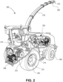
- FIG. 2 illustrates a perspective view of a forage harvester 200, which can be the harvester 106 shown in FIG. 1 , with some portions of the forage harvester being broken away to reveal some internal details of construction.
- FIG. 3 illustrates the forage harvester 200 harvesting crop and transferring a stream of processed crop to a receiving vehicle.
- the harvester 106 can be a forage harvester, such as self-propelled forage harvester 200 illustrated in FIGS. 2 and 3 .
- the forage harvester 200 is supported by front 202 and rear 204 wheels.
- the forage harvester 200 connects to a header 206 suitable for harvesting a foraged crop.
- the header 206 is provided for severing or picking up the crop off the ground and directing it to a series of feed rollers 208 that compact the raw crop material and advance it to one or more chopping drums 210.
- the chopped crop material follows a drum floor 212 to roller crackers 214 that crack grain kernels.
- the processed crop material is blown by an unload conveyor 216 through a discharge chute 218 into a receiving vehicle, such as a wagon 220 pulled by a tractor 222.
- a receiving vehicle such as a wagon 220 pulled by a tractor 222.
- the feed rollers 208, chopping drums 210 and roller crackers 214 constitute a crop processor that takes raw crop material (plants or portions of plants cut or picked up from the field) and reduce the raw crop material to processed crop material (chopped plant matter).
- the discharge chute 218 is a type of unload conveyor as used herein and the end of the chute includes a spout 219.
- the forage harvester 200 advances through a field cutting the crop 224 standing in the field and processes the crop as explained herein.
- the processed crop is transferred from the forage harvester 200 to the wagon 220 by way of the discharge chute 218.
- a stream of processed crop 226 is blown through the chute 218 into the wagon 220.
- the tractor 222 and wagon 220 follow the forage harvester 200 through the field.
- the discharge chute 218 includes base portion 244 attached to a main body portion 246 of the harvester.
- the forage harvester 200 includes an onboard electronic system with similar components to a possible combination of the control system 136 and the computing system 126 which, in some embodiments, includes a controller, position determining device, user interface, sensors, actuators, storage components, input/output ports, a communications gate, a first electromagnetic detecting and ranging module 228 and a second electromagnetic detecting and ranging module 230.
- the modules 228 and 230 each can include a respect LIDAR system and a camera along with corresponding one or more computing devices, to detect and track a location of a receiving vehicle (such as the wagon 220) and at least one of the fill level and content distribution of crop material within the receiving vehicle.
- the data collected by the modules 228 and 230 is used to generate a graphical representation of the unload conveyor 216 of the harvester 200 and the receiving vehicle that is presented to an operator of either the harvester 200 or the tractor 222 by way of a graphical user interface (GUI), e.g., see GUI 1300 as shown in FIGS. 13 and 14 .
- GUI graphical user interface
- the data collected by the modules 228 and 230 can be used to generate guidance data used by at least one of the harvester 200 and the receiving vehicle to automatically guide at least one of the vehicles to maintain proper alignment of the unload conveyor 216 with the receiving vehicle.
- the respective control systems of the vehicles can provide such automation (e.g., see control systems 136 and 138).
- an "unload operation” includes transferring processed crop from a forage harvester to a silage wagon as illustrated in FIG. 3 .
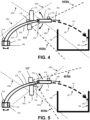
- FIGS. 4 and 5 illustrate side views of two different embodiments of the discharge chute 218 of the forage harvester 200 shown in FIGS. 2 and 3 .
- FIG. 4 shows an embodiment of the discharge chute with the LIDAR system 116 positioned underneath the chute and the camera 117 above the chute
- FIG. 5 shows an embodiment of the chute with the LIDAR system 116 positioned above the chute and the camera 117 underneath the chute.
- an IMU 418 is mounted with LIDAR system 116.
- the chute 218 is shown having spout 219 joined to an arm portion 409 of the chute by a joint 410.
- the joint 410 is configured to permit the spout to pivot vertically up and down relative to the end of the arm portion 409.
- the arm portion 409 of the chute 218 is joined to base portion 244 of the chute at joint 414.
- the joint 414 is configured to permit the arm portion to pivot horizontally relative to a top main body portion of the harvester 200 (e.g., see main body portion 246) as well as relative to the base portion 244.
- the base portion 244 interfaces the arm portion 409 of the chute 218 to the main body portion 246 of the harvester 200.
- Position sensors 412 and 416 are attached to the chute 218.
- the position sensor 412 is configured to sense the position of the spout 219 relative to the arm portion 409.
- the position sensor 416 is configured to sense the position of the arm portion 409 relative to the harvester 200.
- FIGS. 4 and 5 also show a crop material path 401 determined by a computing system (e.g., see any one of the computing systems described herein) that makes the determination by extrapolating points (e.g., see point 411) along an arc formed by a scanned in crop material flow.
- the position of the arm portion 409 of the chute 218 and the position of the spout 219 controls a discharge direction 404 of the spout, the flow of the material starts in the discharge direction 404 and ends when it reaches an inner surface 402 of bin 420 of a receiving vehicle (e.g., see wagon 220).
- the computing system can estimate a landing point 403 based on the crop material path 401 and detection of the inner surface 402.
- the crop material flow (e.g., see stream of processed crop 226) and the inner surface 402 are scanned in by the LIDAR system 116. Also, shown in the FIGS. 4 and 5 , the field of view of the LIDAR system 116, limited by boundaries represented by dashed lines 430a and 430b as well as 430c and 430d, respectively, are able to capture the crop material flow and the inner surface 402 of the bin 420 regardless of being position above the chute 218 or below the chute.
- the LIDAR system and the camera are a part of the harvester 106.
- the crop material flow e.g., see stream of processed crop 226) and the inner surface 402 are detected by the LIDAR system 116 and the camera 117, which provides validation and enhancements in the detection of the flow and the inner surface.
- the field of view of the LIDAR system 116 overlaps the field of view of the camera 117.
- the field of view of the camera 117 is limited by boundaries represented by dotted lines 4030a and 4030b.
- Both the LIDAR system 116 and the camera 117 are able to capture the crop material flow and the inner surface 402 of the bin 420 regardless of being position above the chute 218 or below the chute.
- the camera 117 is above the chute 218 and the LIDAR system 116 is below the chute; and in some other embodiments, the camera 117 is below the chute 218 and the LIDAR system 116 is above the chute.
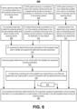
- FIGS. 6 and 7 illustrate example methods 600 and 700 for LIDAR and computer vision detection of path and landing position of crop material expelled from a forage harvester (e.g., see harvester 106, as shown in FIG. 1 , or harvester 200) and use of such information as feedback for operating the harvester or the receiving vehicle (e.g., see receiving vehicle 109 or wagon 220).
- a forage harvester e.g., see harvester 106, as shown in FIG. 1 , or harvester 200
- the receiving vehicle e.g., see receiving vehicle 109 or wagon 220.
- Method 600 begins with a camera capturing image data of a receiving vehicle and a self-propelled vehicle moving the receiving vehicle, at step 602.
- the method also begins with a LIDAR system scanning in coordinates of parts of the receiving vehicle and the self-propelled vehicle as well as scanning in coordinates of a distribution of crop material in the receiving vehicle, at step 604.
- the method also starts with the LIDAR system scanning in a crop material flow expelled from a spout of a discharge chute of a harvester near the receiving vehicle, at step 606.
- the method 600 continues with the computing system processing the captured image data to detect the receiving vehicle and the self-propelled vehicle moving the receiving vehicle and detect a location of the receiving vehicle relative to the harvester, at step 608.
- the method 600 also continues with the computing system determining boundary parameters of a bin of the receiving vehicle based on the scanned in coordinates of the parts of the receiving vehicle and the self-propelled vehicle and the scanned in coordinates of the distribution of crop material in the receiving vehicle, at step 610. Also, the method 600 continues with the computing system determining a crop material path by extrapolating points along an arc formed by the detected crop material flow, at step 612.
- the method 600 continues with the computing system comparing the determined boundary parameters to the processed image data to validate and augment the determined boundary parameters.
- the method 600 continues with the computing system determining an inner surface within the validated and augmented boundary parameters.
- the method 600 continues with the computing system determining a landing point of the expelled crop material flow by curve fitting the determined crop material path to a point of intersection with the determined inner surface, at step 618.
- the method 600 continues with the computing system processing the information determined by the computing system to generate a graphical representation of the processed information or to provide feedback to a control system of the harvester or the self-propelled vehicle moving the receiving vehicle, at 620.
- the determined information that is processed includes the determined boundary parameters of the bin, the determined crop material path, the determined inner surface, and the determined landing point of the crop material flow.
- Method 700 can be in addition to or an alternative of method 600 and it begins with a camera on the harvester capturing image data of a receiving vehicle and a self-propelling vehicle moving the receiving vehicle, at step 702. It also begins with a LIDAR system scanning in coordinates of parts of the receiving vehicle and the self-propelled vehicle as well as scanning in coordinates of a distribution of crop material in the receiving vehicle, at step 704.
- the method 700 continues with a computing system detecting an image of the receiving vehicle from the image data.
- the method 700 continues with generating, by the computing system, a bounding box that surrounds the detected imaged of the receiving vehicle.
- the method continues with the computing system detecting boundaries of the receiving vehicle using edge detection, within the generated bounding box.
- the method 700 continues with the computing system determining fill level based on the detected boundaries and the scanned in coordinates of the distribution of crop material in the receiving vehicle.
- the method 700 continues with the computing system time-matching the captured image data and the scanned in coordinates of the distribution of crop material in the receiving vehicle and the scanned in coordinates of the parts of the receiving vehicle and the self-propelled vehicle to provide time-matched data.
- the method 700 continues with the computing system extracting a receiving vehicle portion of the scanned in coordinates of the parts of the receiving vehicle and the self-propelled vehicle based on the time-matched data and the detected image of the receiving vehicle.
- the method 700 continues with the computing system determining dimensions and orientation of the receiving vehicle based on the extracted receiving vehicle portion.
- the method 700 continues with the computing system processing the information determined by the computing system to generate a graphical representation of the processed information or to provide feedback to a control system of the harvester or the self-propelled vehicle moving the receiving vehicle.
- the determined information that is processed includes at least the determined dimensions and orientation of the receiving vehicle (determined at step 718) and the determined fill level (determined at step 712).
- FIG. 8 is a perspective view of an agricultural harvester 810 illustrating data points collected by the LIDAR system 116 shown in FIGS. 1 , 4, and 5 , wherein the LIDAR system includes a three-dimensional LIDAR scanner.
- the harvester 810 can be the harvester 106 or be replaced by the harvester 200.
- An electromagnetic detecting and ranging module (e.g., see the first electromagnetic detecting and ranging module 228 or the LIDAR system 116) is position at an end of a chute of the harvester 810 (e.g., see chute 218) near or at the spout of the chute (e.g., see spout 219).
- the electromagnetic detecting and ranging module includes a three-dimensional LIDAR scanner positioned to scan an area extending outwardly from a side surface of the harvester 810 and with a center of the scan area being perpendicular or approximately perpendicular to the longitudinal axis of the harvester 810. This corresponds to an area in which a receiving vehicle is located during crop transfer operations.
- the module generates a plurality of data points constituting a point cloud representative of points on surfaces within a scan area, including points on surfaces of the receiving vehicle, the ground and other objects within the scan area.
- a portion of a point cloud 862 is depicted in FIG. 8 illustrating some of the data points corresponding to the receiving vehicle and a tractor pulling the receiving vehicle.
- One or more computing devices receive the data generated by the module and use the data to detect the presence of the receiving vehicle and to determine the location of the receiving vehicle relative to the harvester 810. To detect the presence of the receiving vehicle, the one or more computing devices process the data received from the module to determine whether one or more features or characteristics of the receiving vehicle are present in the data.
- a pattern 864 in the point cloud 862 corresponding to an exterior side surface of the receiving vehicle is visible including a front edge, a top edge, a rear edge and a bottom edge of the surface shown in the pattern 864.
- the one or more computing devices process the data to identify the presence of a surface that approximately matches the anticipated shape, size, angle and/or location of a surface of the receiving vehicle. It does this by looking for a pattern in the point cloud corresponding to a flat surface.
- the one or more computing devices can use preexisting data sets corresponding to the particular receiving vehicle to identify patterns from the data acquired by the electromagnetic detecting and ranging modules.
- the one or more computing devices use the data from the module to determine the orientation and the dimensions of the receiving vehicle.
- the one or more computing devices determine whether the surface corresponding to the size of the receiving vehicle is parallel with the harvester 810 (that is, a front portion of the grain cart is approximately the same distance from the module as a rear portion), or whether a front portion of the receiving vehicle is further from or closer to the module than a rear portion of the receiving vehicle.
- the one or more computing devices can use the orientation of the receiving vehicle to determine, for example, if the receiving vehicle is following parallel with the harvester 810 or is separating from the harvester 810.
- the one or more computing devices determine the dimensions (or approximate dimensions) of the receiving vehicle by identifying a front edge, rear edge and top edge of the point cloud 862.
- the one or more computing devices can use the dimensions of the receiving vehicle in determining where the spout of the unload conveyor is located relative to the edges of the bin of the receiving vehicle to accurately generate a graphical depiction of the relative positions of the unload conveyor and the bin and present the graphical depiction on a graphical user interface. In some embodiments, the one or more computing devices use the dimensions of the receiving vehicle to determine where the spout of the unload conveyor or chute is located relative to the edges of the bin of the receiving vehicle in automatically controlling crop transfer to only transfer crop from the harvester 810 to the receiving vehicle while the spout is over the bin.
- the one or more computing devices use data from the module to determine and track the location of the receiving vehicle relative to the harvester 810. Tracking the location of the receiving vehicle relative to the harvester 810 can involve determining two variables-the lateral distance of the receiving vehicle from the harvester 810 and the longitudinal offset of the receiving vehicle relative to the harvester 810.
- Each of the data points making up the point cloud 862 includes a distance value indicating a distance from the module, therefore determining the lateral distance of the receiving vehicle from the harvester 810 involves using the distance values of the relevant points in the point cloud 862, such as the points defining the pattern 864 corresponding to the exterior surface of the receiving vehicle. If the average distance of to the data points corresponding to the surface is six meters, for example, the lateral distance of the receiving vehicle from the harvester 810 is six meters.
- the one or more computing devices determine the location of one or more features of the receiving vehicle within the field of view of the module and, in particular, whether the feature(s) is to the left or to the right of a center of the scan area of the module. If the center of the exterior surface of the receiving vehicle is determined to be at the center of the field of view of the module, for example, the receiving vehicle is determined to have a longitudinal offset of zero. If the center of the exterior surface of the receiving vehicle is determined to be ten degrees to the left of the center of the field of view, the receiving vehicle has a negative longitudinal offset corresponding to a distance that is determined using the lateral distance and the angle of ten degrees. If the center of the exterior surface of the receiving vehicle is determined to be ten degrees to the right of the center of the field of view, the receiving vehicle has a positive longitudinal offset corresponding to a distance that is determined using the lateral distance and the angle of ten degrees.
- FIG. 9A illustrates data points collected by the LIDAR system 116 shown in FIGS. 1 , 4, and 5 when placed near an empty bin of a receiving vehicle, wherein the LIDAR system includes a two-dimensional LIDAR scanner.
- FIG. 9B illustrates data points collected by the LIDAR system 116 shown in FIGS. 1 , 4, and 5 when placed near a partially filled bin of a receiving vehicle, wherein the LIDAR system includes a two-dimensional LIDAR scanner.
- a two-dimensional LIDAR scanner of the LIDAR system 116 is configured to generate a plurality of data points within a plane corresponding to a scanned area.
- Each data point of the plurality of data points includes a distance value corresponding to a distance from the LIDAR system 116 or a scanner of the LIDAR system.
- one or more computing devices process the data from the LIDAR system to identify patterns.
- a series of data points generated by the LIDAR system when the bin of the receiving vehicle is empty is illustrated in FIG. 9A .
- a first pattern 866 of the data points corresponds to an interior surface of a front wall of a bin
- a second pattern 868 corresponds to an interior surface of a floor of the bin
- a third pattern 870 corresponds to an interior surface of a rear wall of the bin.
- a series of data points generated by the LIDAR system 116 when the bin is partially filled is illustrated in FIG.
- the generally vertical patterns near the front data pattern 972 and the near the rear data pattern 974 of the data set correspond to the front and rear walls of the bin while the data points 976 corresponding to the generally diagonal angled and curved patterns between the front and rear walls correspond to a top surface of a quantity of crop heaped in the bin.
- the top surface scanned in by the LIDAR system 116 represents a scanned in distribution of crop material 902
- the one or more computing devices use the data generated by the LIDAR system 116 to determine one or more fill levels or topography of a bin of a receiving vehicle. To determine a fill level of a bin. the one or more computing devices identify data points 976 corresponding to crop (verses data points corresponding to walls or the floor of the bin), determine a fill height of each of the data points corresponding to crop, and then average the fill height of the data points corresponding to crop to generate an average fill level of the bin.
- the one or more computing devices can use patterns in the data, receiving vehicle location information generated using data from the LIDAR system 116, or both.
- the one or more computing devices can use patterns in the data by identifying patterns corresponding to certain parts of the bin such as a front wall (e.g., see front data pattern 972), rear wall (e.g., see rear data pattern 974) and floor (e.g., see pattern 868) or a combination of two or more of these features.
- a front wall e.g., see front data pattern 972
- rear wall e.g., see rear data pattern 974
- floor e.g., see pattern 868
- the front wall and the rear wall are identified from the data patterns 972 and 974.
- the one or more computing devices determine a fill height of each of the data points corresponding to crop, wherein the fill height is the distance of the data point from the floor of the bin to the data point.
- the fill height can be determined by comparing the location of the data point to the anticipated location of the floor. In the illustrated data patterns, this can involve comparing the data points 976 to second pattern 868.
- the one or more computing devices can also use receiving vehicle location information from LIDAR system 116 to determine or assist in determining the fill level of the bin of the receiving vehicle. If the location of the receiving vehicle relative to the harvester (e.g., see harvester 106 or 200) is known the vehicle's location relative to the unload conveyor can be used to determine the height of the data points corresponding to crop relative to the floor of the bin by comparing the location of the data point to the location of the floor of the bin determined using the location of the receiving vehicle.
- the one or more computing devices determine a distribution of crop in the bin. Using the data pattern illustrated in FIG. 8 or FIG. 9B , for example, the fill height of each data point is determined as explained herein and a fill height value and longitudinal (distance from the rear wall or from the front wall) is stored for each data point. That information can then be used by the one or more computing devices to depict a fill level at various locations in the bin in a GUI, as discussed herein.
- the one or more computers can compare the measured surface of crop material with a top of the receiving vehicle, for example.
- the top of the receiving vehicle can be determined using data generated by the LIDAR system 116, using the data patterns 972 and 974 generated by the LIDAR system, using data provided by an operator or manufacturer of the bin of the receiving vehicle, or a combination thereof.
- the patterns from point cloud 862, depicted in FIG. 8 can be used too.
- the one or more computing devices can detect patterns in the data generated by the LIDAR system 116 by comparing data generated by the LIDAR system with preexisting data corresponding to the receiving vehicle.
- the preexisting data is collected by the LIDAR system 116 (or similar system) or is generated by another sensor or a computer to simulate such data and provides the one or more computing devices known data patterns corresponding to the receiving vehicle.
- the one or more computing devices compare the data generated by the LIDAR system 116 with the preexisting data to identify such patterns as the exterior side surface of the receiving vehicle, edges of the receiving vehicle, the interior surfaces of the front wall, floor and rear wall of the bin, or features of the tractor such as the rear and front wheels.
- Preexisting data can be similar to the data set depicted in FIG. 9A or FIG. 8 , for example, and data generated by the LIDAR system 116 during an operation can be similar to the data set depicted in FIG. 9B or FIG 8 .
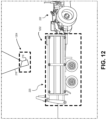
- FIGS. 10 , 11 , and 12 illustrate computer generated images of at least the receiving vehicle and a tractor pulling the receiving vehicle that can be used by the computing systems described herein to validate the information obtained by the LIDAR system, in accordance with some embodiments of the present disclosure.
- FIG. 10 shows computer vision generated bounding boxes 1002 and 1004 that are rectangular and graphically identify the detected image parts of the receiving vehicle and the tractor pulling the receiving vehicle, respectively, by at least partially surrounding the parts.
- FIG. 11 shows computer vision generated bounding boxes 1102 and 1104 that are rectangular cuboidal and graphically identify the detected image parts of the receiving vehicle and the tractor pulling the receiving vehicle, respectively, by at least partially surrounding the parts.
- FIG. 10 shows computer vision generated bounding boxes 1002 and 1004 that are rectangular and graphically identify the detected image parts of the receiving vehicle and the tractor pulling the receiving vehicle, respectively, by at least partially surrounding the parts.
- FIG. 11 shows computer vision generated bounding boxes 1102 and 1104 that are rectangular cuboidal and graphically identify the detected image parts of the receiving vehicle and the
- FIG. 12 shows computer vision generated bounding boxes 1202 and 1204 that are rectangular and graphically identify the detected image parts of the receiving vehicle or wagon 220 and the spout 219 of the discharge chute 218, respectively, by at least partially surrounding the parts. Also, FIG. 12 shows tractor 222 pulling wagon 220.
- FIGS. 13 and 14 illustrates a GUI 1300 including a graphical representation of relative positions of a harvester 1302 and a receiving vehicle 1304.
- Harvester 1302 can be any one of the harvesters described herein.
- Receiving vehicle 1304 can be any one of the receiving vehicles described herein.
- Any one of the computing systems described herein use the data generated by the LIDAR system (e.g., LIDAR system 116) and the camera (e.g., camera 117) to generate graphic data defining a graphical representation illustrating the relative positions of the discharge chute 1322 and spout 1324 of the harvester 1302 and the bin of the receiving vehicle 1304 and illustrating at least one of the fill level 1306 and the distribution of processed crop 1308 in the bin as well as the crop flow 1326 being expelled from the spout and into the bin.
- LIDAR system e.g., LIDAR system 116
- the camera e.g., camera 117
- This graphical representation assists an operator in manually guiding either the tractor or the harvester 1302 (e.g., see harvester 200 and tractor 222) to align the discharge chute 1322, spout 1324, and crop flow 1326 with the bin of the receiving vehicle 1304.
- a visual representation of the fill level 1306 of the bin allows the operator to see whether or not the receiving vehicle is full and to estimate how much time is required to completely fill the receiving vehicle 1304.
- a visual representation of the distribution of crop in the bin allows the operator to see which portions of the bin are full and to adjust the position of the receiving vehicle 2804 relative to the chute 1322, spout 1324, and crop flow 1326 to fill portions of the bin with less crop.
- the graphical representation can be presented on a user interface of the harvester 1302, on a user interface of the tractor moving the receiving vehicle 1304, on a user interface of a portable electronic device such as a table computer or a smartphone, or on any combination thereof (e.g., see the computing system 102 shown in FIG. 1 ).
- the harvester 1302 or any other harvester described herein can be in wireless communication with the receiving vehicle 1304 or any other type of receiving vehicle having wireless communication capabilities, and a computing system of the harvester 1302 (e.g., see computing system 126 shown in FIG. 1 ) generates and communicates the graphical representation to the receiving vehicle as a wireless communication.
- the tractor includes an electronic system similar to that of the harvester 1302, including a communications gateway, a controller and a user interface.
- the harvester 1302 communicates the graphic data via the communications gateway of the harvester and the tractor receives the graphic data via the communications gateway of the tractor, wherein the user interface on the tractor generates the graphical representation from the graphic data and presents the graphical representation to the operator on the user interface.
- the harvester 1302 or any harvester described herein can be in wireless communication with the receiving vehicle and with a portable electronic device (e.g., see computing system 102) wherein a computing device on the harvester generates and communicates the graphical representation to the receiving vehicle, to the portable electronic device, or both as a wireless communication.
- the portable electronic device can be placed in the operator cabin of the harvester, in the operator cabin of the tractor, or another location that is not in the harvester or in the tractor.
- the portable electronic device receives the graphic data from the harvester 1302 or any other harvester described herein through a wireless transceiver on the portable electronic device.
- the graphical representation is presented as part of a GUI on a portable electronic device in FIGS. 13 and 14 for illustration purposes, with the understanding that the graphical representation can be presented on a display that is part of a display console in the receiving vehicle 1304 or in the harvester 1302 or the tractor.
- the graphical representation of the receiving vehicle 1304, the harvester 1302 and their relative positions enables the operator of the tractor to guide the tractor to a location relative to the harvester 1302 where the bin of the receiving vehicle 1304 is properly aligned with the discharge chute 1322 and the spout 1324 as well as the crop flow 1326.
- the receiving vehicle 1304 and the harvester 1302 are depicted in an overhead view 1310 (that is, from a perspective directly above the machines and looking down) so that the operator can clearly see from the graphic representation the relative positions of the receiving vehicle and the harvester in the GUI 1300.
- the fill level and distribution of the crop are also presented to the operator via the GUI 1300 via a side view 1312 of the receiving vehicle.
- the fill level 1306 depicts the fill level of the bin if the crop in the bin were evenly distributed.
- the curved line 1307 depicts the distribution of the crop enabling the operator to adjust the position of the bin relative to the chute 1322, spout 1324, and crop flow 1326 to fill areas of the bin where the level of the crop is lower.
- FIG. 14 depicts an alternative implementation of the graphical representation similar to that of FIG.
- the graphical depiction of the receiving vehicle does not include the distribution of crop (only the fill level) and where the depiction of the receiving vehicle and the harvester includes concentric target lines around the graphical depiction of the spout of the discharge chute to assist the operator in aligning the chute with the bin of the receiving vehicle.
- the embodiments of the GUI depicted in FIGS. 13 and 14 illustrate the chute 218 in a deployed position.
- the computing system can use data from the LIDAR system and the camera to detect the position of the chute relative to the body of the harvester 1302.
- the computing system use the data generated by the LIDAR system and the camera to determine the position of the chute 218 and generate the graphic data such that the graphical representation indicates the position of the chute relative to the body of the harvester 1302 and the receiving vehicle 1304.
- a visual indication of the position of the chute 218 helps the operator know when it is safe to begin unloading crop by enabling the operator to see when the spout of the chute 218 is positioned over the bin of the receiving vehicle 1304.
- the one or more computing devices use data from the LIDAR system and camera to determine the position of the chute 218 to ensure that crop transfer begins only when the chute 218 is in the proper position, to confirm the position of the chute as detected by other sensors, or both.
- captured image data and scanned in LIDAR data can be used by the computing system to determine when an actual amount of crop material within the bin has reached or exceeded a threshold amount.
- the threshold amount can be represented by fill level 1306.
- Processed image data includes the actual amount of crop material within a bin and an indication of whether the actual amount has reached or exceeds the threshold amount
- a generated graphic of the receiving vehicle includes the actual amount of crop material within the bin and the indication of whether the actual amount has reached or exceeds the threshold amount.
- the GUI 1300 provides an indication of the amount of crop material 1330 exceeding the threshold amount or level with warnings 1332.
- a control system of a vehicle (such as the tractor) moving the receiving vehicle 1304 controls the vehicle to avoid or limit the exceeding of the threshold fill level.
- a control system of the harvester 1302 can control the harvester to avoid or limit the filling of the bin to exceed the threshold fill level.
- the control systems can be configured to control steering and propulsion of the vehicles based on processed image data or processed LIDAR data or a combination thereof.
- the warnings 1332 of exceeding the threshold are shown in the overhead view 1310 as bolded "X" characters and in the side view 1312 of the GUI 1300 as triangles including an "! character.
- the GUI 1300 in the overhead view 1310 provides fill levels of the crop within the bin of the receiving vehicle 1304.
- the different fill levels of the crop material are part of a topography of the crop material within the bin of the receiving vehicle and the generated receiving vehicle graphic includes a topography map 1340 of the topography of the crop material within the bin.
- FIG. 14 also depicts the receiving vehicle 1304 and the harvester 1302 along with concentric target lines 1350 around the graphical depiction of an end of the crop flow 1326 being dispensed from the spot 1324 of the chute 1322 to assist the operator in aligning the end of the crop flow with a position in the bin of the receiving vehicle.
- FIG. 15 illustrates a block diagram of example aspects of a computing system (such as shown by computing system 102 in FIG. 1 ) or a computing system locally connected to or integrated with a networked vehicle (such as computing systems 126 and 128), in accordance with some embodiments of the present disclosure.
- a computing system such as shown by computing system 102 in FIG. 1
- a computing system locally connected to or integrated with a networked vehicle (such as computing systems 126 and 128), in accordance with some embodiments of the present disclosure.
- FIG. 15 illustrates parts of the computing system 1500 within which a set of instructions, for causing the machine to perform any one or more of the methodologies discussed herein, are executed.
- the computing system 1500 corresponds to a host system that includes, is coupled to, or utilizes memory or is used to perform the operations performed by any one of the computing devices, data processors, user interface devices, and sensors described herein.
- the machine is connected (e.g., networked) to other machines in a LAN, an intranet, an extranet, or the Internet.
- the machine operates in the capacity of a server or a client machine in client-server network environment, as a peer machine in a peer-to-peer (or distributed) network environment, or as a server or a client machine in a cloud computing infrastructure or environment.
- the machine is a personal computer (PC), a tablet PC, a cellular telephone, a web appliance, a server, a network router, a switch or bridge, or any machine capable of executing a set of instructions (sequential or otherwise) that specify actions to be taken by that machine.
- PC personal computer
- tablet PC a tablet PC
- a cellular telephone a web appliance
- server a server
- network router a switch or bridge
- any machine capable of executing a set of instructions (sequential or otherwise) that specify actions to be taken by that machine.
- the term "machine” shall also be taken to include any collection of machines that individually or jointly execute a set (or multiple sets) of instructions to perform any one or more of the methodologies discussed herein.
- the computing system 1500 includes a processing device 1502, a main memory 1504 (e.g., read-only memory (ROM), flash memory, dynamic random-access memory (DRAM), etc.), a static memory 1506 (e.g., flash memory, static random-access memory (SRAM), etc.), and a data storage system 1510, which communicate with each other via a bus 1530.
- main memory 1504 e.g., read-only memory (ROM), flash memory, dynamic random-access memory (DRAM), etc.
- static memory 1506 e.g., flash memory, static random-access memory (SRAM), etc.
- SRAM static random-access memory
- the processing device 1502 represents one or more general-purpose processing devices such as a microprocessor, a central processing unit, or the like. More particularly, the processing device is a microprocessor or a processor implementing other instruction sets, or processors implementing a combination of instruction sets. Or, the processing device 1502 is one or more special-purpose processing devices such as an application specific integrated circuit (ASIC), a field programmable gate array (FPGA), a digital signal processor (DSP), network processor, or the like. The processing device 1502 is configured to execute instructions 1514 for performing the operations discussed herein. In some embodiments, the computing system 1500 includes a network interface device 1508 to communicate over the communication network 104 shown in FIG. 1 .
- ASIC application specific integrated circuit
- FPGA field programmable gate array
- DSP digital signal processor
- the data storage system 1510 includes a machine-readable storage medium 1512 (also known as a computer-readable medium) on which is stored one or more sets of instructions 1514 or software embodying any one or more of the methodologies or functions described herein.
- the instructions 1514 also reside, completely or at least partially, within the main memory 1504 or within the processing device 1502 during execution thereof by the computing system 1500, the main memory 1504 and the processing device 1502 also constituting machine-readable storage media.
- the instructions 1514 include instructions to implement functionality corresponding to any one of the computing devices, data processors, user interface devices, I/O devices, and sensors described herein. While the machine-readable storage medium 1512 is shown in an example embodiment to be a single medium, the term “machine-readable storage medium” should be taken to include a single medium or multiple media that store the one or more sets of instructions. The term “machine-readable storage medium” shall also be taken to include any medium that is capable of storing or encoding a set of instructions for execution by the machine and that cause the machine to perform any one or more of the methodologies of the present disclosure. The term “machine-readable storage medium” shall accordingly be taken to include, but not be limited to, solid-state memories, optical media, and magnetic media.
- computing system 1500 includes user interface 1520 that includes a display, in some embodiments, and, for example, implements functionality corresponding to any one of the user interface devices disclosed herein.
- a user interface such as user interface 1520, or a user interface device described herein includes any space or equipment where interactions between humans and machines occur.
- a user interface described herein allows operation and control of the machine from a human user, while the machine simultaneously provides feedback information to the user. Examples of a user interface (UI), or user interface device include the interactive aspects of computer operating systems (such as GUIs), machinery operator controls, and process controls.
- a UI described herein includes one or more layers, including a human-machine interface (HMI) that interfaces machines with physical input hardware such as keyboards, mice, or pads, and output hardware such as monitors, speakers, and printers.
- HMI human-machine interface
- such a UI also includes a device that implements an HMI-also known as a human interface device (HID).
- HMI- human interface device
- a GUI which is composed of a tactile UI and a visual UI capable of displaying graphics, or any other type of UI presents information to a user of the system related to systems and methods for LIDAR detection of path and landing position of crop material expelled from a forage harvester and use of such information as feedback for operating the harvester or the receiving vehicle.
- sound is added to a GUI, such that the UI is a multimedia user interface (MUI) that provides information related to systems and methods for crop row guidance.
- UI described herein also include virtual reality or augmented reality aspects, in some examples.
- computing system 1500 includes sensors 1522 that implement functionality corresponding to any one of the sensors or cameras disclosed herein (e.g., see LIDAR system 116 and camera 117).
- the sensors 1522 include a LIDAR system that implements LIDAR functionality in any one of the methodologies described herein.
- the sensors 1522 include a device, a module, a machine, or a subsystem that detect objects, events or changes in its environment and send the information to other electronics or devices, such as a computer processor or a computing system in general.
- the sensors 1522 additionally include a position sensor, a linear displacement sensor, an angular displacement sensor, a pressure sensor, a load cell, or any other sensor useable to sense a physical attribute of an agricultural vehicle related to driving and steering of the vehicle or related to control of a discharge chute, or any combination thereof.
- a system of the technologies described herein includes a controller of an agricultural vehicle.
- the system also includes one or more sensors and cameras of the vehicle connected to the controller.
- the combination of the sensor(s) and camera(s) as well as the controller perform the steps of the methods described herein to provide LIDAR detection of path and landing position of crop material expelled from a forage harvester and use of such information as feedback for operating the harvester or the receiving vehicle.
- such information is outputted to the operator, via a user interface (Ul), such as via user interface 1520.
- the output to the operator is provided in real time during operation of the vehicle, for example.
- the determined information is determined using machine learning or the determined information is enhanced via machine learning.
- the signal processing described herein also incorporates machine learning in some embodiments.
- the informational output is displayed to a user via a UI to enhance operations of the vehicle manually or is used as feedback information to the controller so that the controller automatically enhances operations of the vehicle with or without manual input.
- a UI to enhance operations of the vehicle manually
- FIGS. 13 and 14 is an illustration of a GUI providing such information to guide an operator of the harvester or the receiving vehicle.
- the present disclosure also relates to an apparatus for performing the operations herein.
- This apparatus can be specially constructed for the intended purposes, or it can include a general-purpose computer selectively activated or reconfigured by a computer program stored in the computer.
- a computer program can be stored in a computer readable storage medium, such as, but not limited to, any type of disk including floppy disks, optical disks, CD-ROMs, and magnetic-optical disks, read-only memories (ROMs), random access memories (RAMs), EPROMs, EEPROMs, magnetic or optical cards, or any type of media suitable for storing electronic instructions, each coupled to a computing system bus.
- the present disclosure can be provided as a computer program product, or software, that can include a machine-readable medium having stored thereon instructions, which can be used to program a computing system (or other electronic devices) to perform a process according to the present disclosure.
- a machine-readable medium includes any mechanism for storing information in a form readable by a machine (e.g., a computer).
- a machine-readable (e.g., computer-readable) medium includes a machine (e.g., a computer) readable storage medium such as a read only memory (“ROM”), random access memory (“RAM”), magnetic disk storage media, optical storage media, flash memory components, etc.
Landscapes
- Life Sciences & Earth Sciences (AREA)
- Environmental Sciences (AREA)
- Management, Administration, Business Operations System, And Electronic Commerce (AREA)
- Guiding Agricultural Machines (AREA)
- Control Of Position, Course, Altitude, Or Attitude Of Moving Bodies (AREA)
Abstract
Description
- The present disclosure relates to systems and methods for detecting crop material path and landing position of a harvester output, and specifically, for example, systems and methods for detecting crop material path and landing position of a forage harvester output. Some embodiments relate to forage harvester systems and methods for automated and semi-automated filing of bins of receiving vehicles.
- Harvesters, such as forage harvesters, are used in agricultural production to cut or pick up crops from a field. In the case of forage harvesters, a harvester cuts and picks up forage plants and then dispenses the cut plants to a wagon. The harvested forage plants are made into silage.
- Forage harvesters can be implements attached to a tractor or be self-propelled machines. Forage harvesters can include a drum or a flywheel with blades that chop and blow the cut crop out of a chute of the harvester into a wagon that is either connected to the harvester or to another vehicle moving the wagon alongside the harvester. Forage harvesters can have paddle accelerators to increase the flow of the forage harvester output. Once filled, the wagon can be unloaded and the unloaded silage can be stored. Corn and grass require different types of cutting equipment; thus, there are different heads for each type of crop, and in some examples, the heads are attachable and detachable from the harvester.
- To avoid stopping during a harvesting operation, a forage harvester unloads the crop while the harvester is in motion harvesting crop. Unloading the forage harvester while it is in motion requires a receiving vehicle to drive alongside the harvester during the unload operation. This requires the operator driving the receiving vehicle to align a bin of the receiving vehicle with the spout of an unload conveyor of the forage harvester for the duration of the unload operation. Aligning the two vehicles in this manner is laborious for the operator of the receiving vehicle and, in some situations, can be particularly challenging. Some circumstances may limit the operator's visibility, for example, such as where there is excessive dust in the air or at nighttime. Furthermore, if the receiving vehicle has a large or elongated bin it is desirable to shift the position of the bin relative to the spout during the unload operation to evenly fill the grain bin and avoid spilling grain.
- Another type of harvester is a combine harvester. Combine harvesters also process crop but function differently from forage harvesters. A combine harvester separates grain from material other than grain (MOG), such as stalks, leaves, and husks; whereas, forage harvesters chop the entire plant-including grain and MOG-into small pieces for storage and feeding to livestock. Combine harvesters may store the processed crop onboard the harvester during the harvest operation, rather than transfer the processed crop to a receiving vehicle by blowing the crop material through a discharge chute to the receiving vehicle during the harvesting operation. However, similar to forage harvesters, some combine harvesters may also transfer the processed crop to a receiving vehicle by blowing the crop material through a discharge chute to the receiving vehicle during the harvesting operation. Thus, a receiving vehicle must closely follow such a combine harvester during the entire harvester operation. This presents similar challenges to those discussed herein in relation to the forage harvester.
- The above section provides background information related to the present disclosure which is not necessarily prior art.
- Described herein are technologies (such as systems, apparatuses, and methods) that use light detection and ranging (LIDAR) and computer vision to detect a location of a receiving vehicle relative to a forage harvester, fill levels of crop material within the receiving vehicle, and path and landing position of material expelled from the forage harvester and received by a bin of the receiving vehicle. The technologies use such information as feedback for operating the harvester or the receiving vehicle. Some embodiments detect ground level in front of the harvester or the receiving vehicle, and such information is used as feedback too. Some embodiments include a link to communicate the feedback to a graphical user interface (GUI) for user visualization of the feedback and semi-automated operations of the harvester or the receiving vehicle. For example, readings from LIDAR and a camera of the harvester detect a topography of the material deposited in the bin of the receiving vehicle, and a GUI outputs the topography.
- In providing detecting crop material path and landing position of a harvester output and using such information for feedback control as well as providing forage harvester systems and methods for automated and semi-automated filing of bins of receiving vehicles, the technologies described herein overcome some technical problems in farming of crops and specifically some technical problems in harvesting crops and aligning harvester output with a bin of a receiving vehicle. Also, the techniques disclosed herein provide specific technical solutions to at least overcome the technical problems mentioned in the background section and other parts of the application as well as other technical problems not described herein but recognized by those skilled in the art.
- With respect to some embodiments, disclosed herein are computerized methods for detecting crop material path and landing position of a harvester output and using such information for feedback control as well as for automated and semi-automated filing of bins of receiving vehicles by the harvester, as well as a non-transitory computer-readable storage medium for carrying out technical operations of the computerized methods. The non-transitory computer-readable storage medium has tangibly stored thereon, or tangibly encoded thereon, computer readable instructions that when executed by one or more devices (e.g., one or more personal computers or servers) cause at least one processor to perform a method for detecting crop material path and landing position of a harvester output and using such information for feedback control as well as for automated and semi-automated filing of bins of receiving vehicles by the harvester.
- These and other important aspects of the invention are described more fully in the detailed description below. The invention is not limited to the particular methods and systems described herein. Other embodiments can be used and changes to the described embodiments can be made without departing from the scope of the claims that follow the detailed description.
- The present disclosure will be understood more fully from the detailed description given below and from the accompanying drawings of various embodiments of the disclosure.
-
FIG. 1 illustrates an example network of agricultural vehicles as well as systems and apparatuses that provide for detecting crop material path and landing position of a harvester output and using such information for feedback control, wherein a harvester providing the output includes a camera and wherein the data captured by the camera verifies data captured by a LIDAR and further enhances detecting crop material path and landing position of the harvester output and using such information for feedback control, in accordance with some embodiments of the present disclosure. -
FIG. 2 illustrates a perspective view of a forage harvester, which can be the harvester shown inFIG. 1 , with some portions of the forage harvester being broken away to reveal some internal details of construction, in accordance with some embodiments of the present disclosure. -
FIG. 3 illustrates the forage harvester ofFIG. 2 harvesting crop and transferring a stream of processed crop to a receiving vehicle, in accordance with some embodiments of the present disclosure. -
FIGS. 4 and 5 illustrate side views of two different embodiments of the discharge chute of the forage harvester shown inFIGS. 2 and3 , with some portions of the forage harvester and the receiving vehicle being broken away or completely removed to reveal some internal details of construction, wherein the embodiments include a camera and a light detection and ranging (LIDAR) system, in accordance with some embodiments of the present disclosure. -
FIGS. 6 and7 illustrate example methods for LIDAR and computer vision detection of path and landing position of crop material expelled from a forage harvester and use of such information as feedback for operating the harvester or the receiving vehicle, in accordance with some embodiments of the present disclosure. -
FIG. 8 is a perspective view of an agricultural harvester illustrating data points collected by the LIDAR system shown inFIGS. 1 ,4, and 5 , wherein the LIDAR system includes a three-dimensional LIDAR scanner, in accordance with some embodiments of the present disclosure. -
FIG. 9A illustrates data points collected by the LIDAR system shown inFIGS. 1 ,4, and 5 when placed near an empty bin of a receiving vehicle, wherein the LIDAR system includes a two-dimensional LIDAR scanner, in accordance with some embodiments of the present disclosure. -
FIG. 9B illustrates data points collected by the LIDAR system shown inFIGS. 1 ,4, and 5 when placed near a partially filled bin of a receiving vehicle, wherein the LIDAR system includes a two-dimensional LIDAR scanner, in accordance with some embodiments of the present disclosure. -
FIGS. 10 ,11 , and12 illustrate computer generated images of at least the receiving vehicle and a tractor pulling the receiving vehicle that can be used by the computing systems described herein to validate the information obtained by the LIDAR system, in accordance with some embodiments of the present disclosure. -
FIGS. 13 and14 illustrates a graphical user interface (GUI) including a graphical representation of relative positions of an agricultural harvester and a receiving vehicle. -
FIG. 15 illustrates a block diagram of example aspects of a computing system (such as shown bycomputing system 102 inFIG. 1 ) or a computing system locally connected to or integrated with a networked vehicle (such ascomputing systems 126 and 128), in accordance with some embodiments of the present disclosure. - Details of example embodiments of the invention are described in the following detailed description with reference to the drawings. Although the detailed description provides reference to example embodiments, it is to be understood that the invention disclosed herein is not limited to such example embodiments. But to the contrary, the invention disclosed herein includes numerous alternatives, modifications and equivalents as will become apparent from consideration of the following detailed description and other parts of this disclosure.
-
FIG. 1 illustratesnetwork 100 including multiple computing systems (e.g., seecomputing system communication network 104, and agricultural vehicles, e.g., seeharvester 106, self-propelling vehicle 108, and receiving vehicle 109). - The
harvester 106 can be a forage harvester or a combine harvester. In examples whereharvester 106 is a forage harvester, it can be a self-propelling forage harvester or a forage harvester attachable to a tractor. Thereceiving vehicle 109 can be a receiving vehicle or a wagon or part of the self-propellingvehicle 108. In the example, where thereceiving vehicle 109 is part of the self-propellingvehicle 108, the receiving vehicle is essentially a self-propelling vehicle. The self-propellingvehicle 108 can be a tractor or a truck or another type of self-propelling vehicle. As shown, the self-propellingvehicle 108 includes acomputing system 128 and acontrol system 138. In some embodiments, thecomputing system 128 and thecontrol system 138 are systems of the receivingvehicle 109 as well. Also, as shown, the harvester includes a light detection and ranging (LIDAR)system 116, thecomputing system 126, and thecontrol system 136. Thecomputing system 102 is remote to the harvester and the other agricultural vehicles and can provide the functionality ofcomputing systems - Also, the
harvester 106 includes acamera 117 and data captured by the camera verifies data captured by theLIDAR system 116 and further enhances detecting crop material path and landing position of a harvester output and using such information for feedback control. - With respect to
FIG. 1 , some embodiments include an apparatus that includes acamera 117, aLIDAR system 116, and a computing system (e.g., seecomputing system camera 117 is configured to capture image data of a receiving vehicle (e.g., see receiving vehicle 109) and a self-propelled vehicle moving the receiving vehicle (e.g., see self-propelled vehicle 108). TheLIDAR system 116 is configured to: scan in coordinates of parts of the receiving vehicle and the self-propelled vehicle, scan in coordinates of a distribution of crop material in the receiving vehicle, and scan in a crop material flow expelled from a spout of a discharge chute of a harvester near the receiving vehicle, e.g., see stream of processedcrop 226. - In such embodiments, the computing system is configured to determine a crop material path by extrapolating points along an arc formed by the scanned in crop material flow. The computing system is also configured to determine boundary parameters of a bin of the receiving vehicle based on the scanned in coordinates of the parts of the receiving vehicle and the self-propelled vehicle and the scanned in coordinates of the distribution of crop material in the receiving vehicle. Also, the computing system is also configured to process the captured image data to detect the receiving vehicle and the self-propelled vehicle moving the receiving vehicle and detect a location of the receiving vehicle relative to the harvester. Subsequently, the computing system is configured to compare the determined boundary parameters to the processed image data to validate and augment the determined boundary parameters as well as to determine an inner surface within the validated and augmented boundary parameters. Also, the computing system is configured to determine a landing point of the expelled crop material flow by curve fitting the determined crop material path to a point of intersection with the determined inner surface. And, finally, the computing system is configured to process information determined by the computing system to generate a graphical representation of the processed information or to provide feedback to a control system of the harvester or the self-propelled vehicle moving the receiving vehicle. In some instances, the determined landing point is an estimated impact point between the expelled material and the determined inner surface, and the determined inner surface includes crop material or a wall of the bin of the receiving vehicle.
- In some embodiments of the apparatus shown in
FIG. 1 , the computing system is configured to: detect an image of the receiving vehicle from the image data, generate a bounding box that surrounds the detected imaged of the receiving vehicle, and detect boundaries of the receiving vehicle using edge detection, within the generated bounding box. In such embodiments, the computing system is also configured to compare the determined boundary parameters, which were based on the scanned in coordinates, to the detected boundaries within the generated bounding box to validate or augment the determined boundary parameters. - In some embodiments of the apparatus shown in
FIG. 1 , the apparatus also includes the control system. The control system in such embodiments is configured to control a discharge direction of the spout of the discharge chute based on the processed information determined by the computing system. The discharge direction is a direction in which the spout expels the crop material. The control of the discharge direction is at least partially based on the processed image data, the determined landing point, and a target landing point of the crop material. The control system is further configured to determine, via the computing system, control parameters of parts of the discharge chute to control the discharge direction based on the processed image data, the determined landing point, and the target landing point. - In some embodiments of the apparatus shown in
FIG. 1 , in the processing of the captured image data, the computing system is configured to detect a topography of crop material within the receiving vehicle. The processed image data includes the detected topography, and the target landing point is based on the detected topography. Also, in some embodiments, in the processing of the captured image data, the computing system is configured to detect different fill levels of crop material at different regions within the receiving vehicle. The processed image data includes the detected different fill levels, and the target landing point is based on the detected different fill levels. - In some embodiments of the apparatus shown in
FIG. 1 , the discharge chute includes a joint, configured to join the spout to an arm portion of the discharge chute, and includes a position feedback sensor on or near the joint, configured to sense a position of the spout relative to the arm portion of the discharge chute. The control of the discharge direction, by the control system, is further based on the sensed position of the spout. Also, in such embodiments, the computing system is configured to determine a control parameter of the joint based on the sensed position of the spout, the determined landing point, and the target landing point. - In some embodiments of the apparatus shown in
FIG. 1 , the joint is a first joint, the position feedback sensor is a first position feedback sensor, and the discharge chute further includes a second joint and a second position feedback sensor. The second joint is configured to join the arm portion to a base portion of the discharge chute. The base portion of the discharge chute is attached to a main body portion of the harvester. The second position feedback sensor is on or near the second joint and is configured to sense a position of the arm portion relative to the base portion of the discharge chute. The control of the discharge direction, by the control system, is further based on the sensed position of the arm portion. And, the computing system is configured to determine a control parameter of the second joint based on the sensed position of the arm portion, the determined landing point, and the target landing point. - In some embodiments of the apparatus shown in
FIG. 1 , in the processing of the captured image data, the computing system is configured to detect different fill levels of crop material at different regions within the receiving vehicle, and the processed image data includes the detected different fill levels. Also, the generated graphical representation of the processed information includes the detected different fill levels. In some examples, in the processing of the captured image data, the computing system is configured to detect a topography of crop material within the receiving vehicle, and the processed image data includes the detected topography. Also, the generated graphical representation of the processed information includes the detected topography. In some instances, the generated graphical representation of the processed information includes the detected topography within a graphical representation of the bin of the receiving vehicle as well as a graphical representation of an overhead view of the receiving vehicle, the self-propelled vehicle moving the receiving vehicle, and the harvester. - As shown in
FIG. 1 , in some embodiments the apparatus is part of the harvester and the apparatus includes the discharge chute. Also, the LIDAR system and the camera are mounted to the discharge chute, and the discharge chute is configured to pivot on the harvester horizontally. In some of such embodiments, the LIDAR system is mounted above the spout of the discharge chute and the camera is mounted below the spout. In some other embodiments, the LIDAR system is mounted below the spout of the discharge chute and the camera is mounted above the spout. - Also, with respect to
FIG. 1 , some embodiments of an apparatus include a camera, configured to capture image data of a receiving vehicle and a self-propelling vehicle moving the receiving vehicle that is near a harvester, as well as a LIDAR system, configured to: scan in coordinates of parts of the receiving vehicle and the self-propelled vehicle, and scan in coordinates of a distribution of crop material in the receiving vehicle. In such embodiments, the apparatus also includes a computing system, configured to detect an image of the receiving vehicle from the image data and generate a bounding box that surrounds the detected imaged of the receiving vehicle. The bounding box is either a rectangular cuboid or a rectangle. The computing system is also configured to detect boundaries of the receiving vehicle using edge detection, within the generated bounding box. Also, the computing system is configured to estimate fill level based on the detected boundaries and the scanned in coordinates of the distribution of crop material in the receiving vehicle. - Additionally, in such embodiments, the computing system is configured to time-match the captured image data and the scanned in coordinates of the distribution of crop material in the receiving vehicle and the scanned in coordinates of the parts of the receiving vehicle and the self-propelled vehicle to provide time-matched data. Also, the computing system is configured to extract a receiving vehicle portion of the scanned in coordinates of the parts of the receiving vehicle and the self-propelled vehicle based on the time-matched data and the detected image of the receiving vehicle. The computing system is then further configured to estimate dimensions and orientation of the receiving vehicle based on the extracted receiving vehicle portion. Finally, the computing system is configured to generate graphical representations of the estimated fill level and the estimated dimensions and orientation of the receiving vehicle to be displayed on a screen simultaneously.
- In some embodiments of the apparatus shown in
FIG. 1 , the LIDAR system is configured to scan in a crop material flow expelled from a spout of a discharge chute of the harvester. And, the computing system is configured to determine a crop material path by extrapolating points along an arc formed by the scanned in crop material flow as well as determine a landing point of the expelled crop material flow by curve fitting the determined crop material path to a point of intersection with a surface of the receiving vehicle, based on the estimated dimensions and orientation of the receiving vehicle. Also, the computing system is configured to generate a graphical representation of the determined crop material path and the determined landing point along with the estimated fill level and the estimated dimensions and orientation of the receiving vehicle to be displayed on the screen simultaneously. - In some embodiments of the apparatus shown in
FIG. 1 , the computing system is configured to detect an image of the spout from the captured image data and generate a second bounding box that surrounds the detected imaged of the spout. The computing system is also configured to detect boundaries of the spout using edge detection, within the generated second bounding box and extract a spout portion of detected coordinates in the detected crop material flow, based on the time-matched data and the detected image of the spout. Also, the computing system is configured to estimate dimensions and orientation of the spout based on the extracted spout portion of the detected coordinates in the detected crop material flow. Finally, in such an instance, the computing system is configured to generate a graphical representation of the estimated dimensions and orientation of the spout along with the estimated fill level and the estimated dimensions and orientations of the receiving vehicle to be displayed on the screen simultaneously. - In some embodiments of the apparatus shown in
FIG. 1 , the computing system is configured to convert the scanned in coordinates of the receiving vehicle and the self-propelled vehicle into a point cloud and estimate the fill level based on the detected boundaries and the point cloud. Further, the computing system is configured to time-match the captured image data and the point cloud to provide the time-matched data and then extract a receiving vehicle portion of the point cloud based on the time-matched data and the detected image of the receiving vehicle. Finally, the computing system is configured to estimate the dimensions and orientation of the receiving vehicle based on the point cloud. - In some embodiments of the apparatus shown in
FIG. 1 , the computing system is configured to detect an image of the self-propelled vehicle moving the receiving vehicle from the captured image data and generate a second bounding box that surrounds the detected imaged of the self-propelled vehicle. In such an example, the computing system is also configured to detect boundaries of the self-propelled vehicle using edge detection, within the generated second bounding box. It is also configured to extract a moving vehicle portion of the scanned in coordinates associated with the self-propelled vehicle moving the receiving vehicle, based on the time-matched data and the detected image of the self-propelled vehicle and then estimate dimensions and orientation of the self-propelled vehicle based on the extracted moving vehicle portion of the scanned in coordinates. Finally, in such examples, it is configured to generate a graphical representation of the estimated dimensions and orientation of the self-propelled vehicle along with the estimated fill level and the estimated dimensions and orientation of the receiving vehicle to be displayed on the screen simultaneously. - With respect to
FIG. 1 , thecommunication network 104 includes one or more local area networks (LAN(s)) or one or more wide area networks (WAN(s)). In some embodiments, thecommunication network 104 includes the Internet or any other type of interconnected communications network. In some embodiments, thecommunication network 104 includes a single computer network or a telecommunications network. In some embodiments, thecommunication network 104 includes a local area network (LAN) such as a private computer network that connects computers in small physical areas, a wide area network (WAN) to connect computers located in different geographical locations, or a middle area network (MAN) to connect computers in a geographic area larger than that covered by a large LAN but smaller than the area covered by a WAN. - In some embodiments, the agricultural vehicles of the
network 100 are connected to the Internet and thecommunication network 104 includes the Internet. In such examples, the agricultural vehicles are Internet of Things (loT) devices. - Not depicted in
FIG. 1 , thenetwork 100 can include various types of sensors (e.g., see LIDAR system 116). In some embodiments, the sensors also include cameras, position sensors, linear displacement sensors, angular displacement sensors, pressure sensors, load cells, or any other sensor useable to sense physical attributes and locations of agricultural vehicles, such as physical attributes related to steering or driving of a vehicle or moving or adjusting a chute of a harvester. - As shown, at least each shown component of the network 100 (including
computing systems communication network 104,harvester 106,vehicles control systems -
FIG. 2 illustrates a perspective view of aforage harvester 200, which can be theharvester 106 shown inFIG. 1 , with some portions of the forage harvester being broken away to reveal some internal details of construction.FIG. 3 illustrates theforage harvester 200 harvesting crop and transferring a stream of processed crop to a receiving vehicle. - As mentioned, the
harvester 106 can be a forage harvester, such as self-propelledforage harvester 200 illustrated inFIGS. 2 and3 . Theforage harvester 200 is supported byfront 202 and rear 204 wheels. Theforage harvester 200 connects to aheader 206 suitable for harvesting a foraged crop. Theheader 206 is provided for severing or picking up the crop off the ground and directing it to a series offeed rollers 208 that compact the raw crop material and advance it to one or more chopping drums 210. The chopped crop material follows adrum floor 212 toroller crackers 214 that crack grain kernels. From there the processed crop material is blown by an unloadconveyor 216 through adischarge chute 218 into a receiving vehicle, such as awagon 220 pulled by atractor 222. As used herein, thefeed rollers 208, choppingdrums 210 androller crackers 214 constitute a crop processor that takes raw crop material (plants or portions of plants cut or picked up from the field) and reduce the raw crop material to processed crop material (chopped plant matter). Furthermore, thedischarge chute 218 is a type of unload conveyor as used herein and the end of the chute includes aspout 219. - In operation, the
forage harvester 200 advances through a field cutting thecrop 224 standing in the field and processes the crop as explained herein. The processed crop is transferred from theforage harvester 200 to thewagon 220 by way of thedischarge chute 218. A stream of processedcrop 226 is blown through thechute 218 into thewagon 220. Thetractor 222 andwagon 220 follow theforage harvester 200 through the field. - As shown in
FIG. 3 , thedischarge chute 218 includesbase portion 244 attached to amain body portion 246 of the harvester. - The
forage harvester 200 includes an onboard electronic system with similar components to a possible combination of thecontrol system 136 and thecomputing system 126 which, in some embodiments, includes a controller, position determining device, user interface, sensors, actuators, storage components, input/output ports, a communications gate, a first electromagnetic detecting and rangingmodule 228 and a second electromagnetic detecting and rangingmodule 230. Themodules modules conveyor 216 of theharvester 200 and the receiving vehicle that is presented to an operator of either theharvester 200 or thetractor 222 by way of a graphical user interface (GUI), e.g., seeGUI 1300 as shown inFIGS. 13 and14 . Also, the data collected by themodules harvester 200 and the receiving vehicle to automatically guide at least one of the vehicles to maintain proper alignment of the unloadconveyor 216 with the receiving vehicle. The respective control systems of the vehicles can provide such automation (e.g., seecontrol systems 136 and 138). - As used herein, an "unload operation" includes transferring processed crop from a forage harvester to a silage wagon as illustrated in
FIG. 3 . -
FIGS. 4 and 5 illustrate side views of two different embodiments of thedischarge chute 218 of theforage harvester 200 shown inFIGS. 2 and3 .FIG. 4 shows an embodiment of the discharge chute with theLIDAR system 116 positioned underneath the chute and thecamera 117 above the chute, andFIG. 5 shows an embodiment of the chute with theLIDAR system 116 positioned above the chute and thecamera 117 underneath the chute. In both shown examples anIMU 418 is mounted withLIDAR system 116. Thechute 218 is shown havingspout 219 joined to anarm portion 409 of the chute by a joint 410. The joint 410 is configured to permit the spout to pivot vertically up and down relative to the end of thearm portion 409. Thearm portion 409 of thechute 218 is joined tobase portion 244 of the chute at joint 414. The joint 414 is configured to permit the arm portion to pivot horizontally relative to a top main body portion of the harvester 200 (e.g., see main body portion 246) as well as relative to thebase portion 244. Thebase portion 244 interfaces thearm portion 409 of thechute 218 to themain body portion 246 of theharvester 200.Position sensors chute 218. Theposition sensor 412 is configured to sense the position of thespout 219 relative to thearm portion 409. Theposition sensor 416 is configured to sense the position of thearm portion 409 relative to theharvester 200. -
FIGS. 4 and 5 also show acrop material path 401 determined by a computing system (e.g., see any one of the computing systems described herein) that makes the determination by extrapolating points (e.g., see point 411) along an arc formed by a scanned in crop material flow. The position of thearm portion 409 of thechute 218 and the position of thespout 219 controls adischarge direction 404 of the spout, the flow of the material starts in thedischarge direction 404 and ends when it reaches aninner surface 402 ofbin 420 of a receiving vehicle (e.g., see wagon 220). The computing system can estimate alanding point 403 based on thecrop material path 401 and detection of theinner surface 402. The crop material flow (e.g., see stream of processed crop 226) and theinner surface 402 are scanned in by theLIDAR system 116. Also, shown in theFIGS. 4 and 5 , the field of view of theLIDAR system 116, limited by boundaries represented by dashedlines inner surface 402 of thebin 420 regardless of being position above thechute 218 or below the chute. - Also shown in
FIG. 1 and further emphasized byFIGS. 4 and 5 , the LIDAR system and the camera are a part of theharvester 106. The crop material flow (e.g., see stream of processed crop 226) and theinner surface 402 are detected by theLIDAR system 116 and thecamera 117, which provides validation and enhancements in the detection of the flow and the inner surface. Also, shown in theFIGS. 4 and 5 , the field of view of theLIDAR system 116 overlaps the field of view of thecamera 117. The field of view of thecamera 117 is limited by boundaries represented bydotted lines LIDAR system 116 and thecamera 117 are able to capture the crop material flow and theinner surface 402 of thebin 420 regardless of being position above thechute 218 or below the chute. As depicted, in some embodiments, thecamera 117 is above thechute 218 and theLIDAR system 116 is below the chute; and in some other embodiments, thecamera 117 is below thechute 218 and theLIDAR system 116 is above the chute. -
FIGS. 6 and7 illustrateexample methods harvester 106, as shown inFIG. 1 , or harvester 200) and use of such information as feedback for operating the harvester or the receiving vehicle (e.g., see receivingvehicle 109 or wagon 220). -
Method 600 begins with a camera capturing image data of a receiving vehicle and a self-propelled vehicle moving the receiving vehicle, atstep 602. The method also begins with a LIDAR system scanning in coordinates of parts of the receiving vehicle and the self-propelled vehicle as well as scanning in coordinates of a distribution of crop material in the receiving vehicle, atstep 604. The method also starts with the LIDAR system scanning in a crop material flow expelled from a spout of a discharge chute of a harvester near the receiving vehicle, atstep 606. - The
method 600 continues with the computing system processing the captured image data to detect the receiving vehicle and the self-propelled vehicle moving the receiving vehicle and detect a location of the receiving vehicle relative to the harvester, atstep 608. Themethod 600 also continues with the computing system determining boundary parameters of a bin of the receiving vehicle based on the scanned in coordinates of the parts of the receiving vehicle and the self-propelled vehicle and the scanned in coordinates of the distribution of crop material in the receiving vehicle, atstep 610. Also, themethod 600 continues with the computing system determining a crop material path by extrapolating points along an arc formed by the detected crop material flow, atstep 612. - At
step 614, themethod 600 continues with the computing system comparing the determined boundary parameters to the processed image data to validate and augment the determined boundary parameters. Atstep 616, themethod 600 continues with the computing system determining an inner surface within the validated and augmented boundary parameters. - Also, the
method 600 continues with the computing system determining a landing point of the expelled crop material flow by curve fitting the determined crop material path to a point of intersection with the determined inner surface, atstep 618. - Finally, the
method 600 continues with the computing system processing the information determined by the computing system to generate a graphical representation of the processed information or to provide feedback to a control system of the harvester or the self-propelled vehicle moving the receiving vehicle, at 620. The determined information that is processed includes the determined boundary parameters of the bin, the determined crop material path, the determined inner surface, and the determined landing point of the crop material flow. -
Method 700 can be in addition to or an alternative ofmethod 600 and it begins with a camera on the harvester capturing image data of a receiving vehicle and a self-propelling vehicle moving the receiving vehicle, atstep 702. It also begins with a LIDAR system scanning in coordinates of parts of the receiving vehicle and the self-propelled vehicle as well as scanning in coordinates of a distribution of crop material in the receiving vehicle, atstep 704. - At
step 706, themethod 700 continues with a computing system detecting an image of the receiving vehicle from the image data. Atstep 708, themethod 700 continues with generating, by the computing system, a bounding box that surrounds the detected imaged of the receiving vehicle. At step 710, the method continues with the computing system detecting boundaries of the receiving vehicle using edge detection, within the generated bounding box. - At
step 712, themethod 700 continues with the computing system determining fill level based on the detected boundaries and the scanned in coordinates of the distribution of crop material in the receiving vehicle. - At
step 714, themethod 700 continues with the computing system time-matching the captured image data and the scanned in coordinates of the distribution of crop material in the receiving vehicle and the scanned in coordinates of the parts of the receiving vehicle and the self-propelled vehicle to provide time-matched data. - At
step 716, themethod 700 continues with the computing system extracting a receiving vehicle portion of the scanned in coordinates of the parts of the receiving vehicle and the self-propelled vehicle based on the time-matched data and the detected image of the receiving vehicle. Atstep 718, themethod 700 continues with the computing system determining dimensions and orientation of the receiving vehicle based on the extracted receiving vehicle portion. - Finally, at
step 720, themethod 700 continues with the computing system processing the information determined by the computing system to generate a graphical representation of the processed information or to provide feedback to a control system of the harvester or the self-propelled vehicle moving the receiving vehicle. The determined information that is processed includes at least the determined dimensions and orientation of the receiving vehicle (determined at step 718) and the determined fill level (determined at step 712). -
FIG. 8 is a perspective view of anagricultural harvester 810 illustrating data points collected by theLIDAR system 116 shown inFIGS. 1 ,4, and 5 , wherein the LIDAR system includes a three-dimensional LIDAR scanner. Theharvester 810 can be theharvester 106 or be replaced by theharvester 200. - An electromagnetic detecting and ranging module (e.g., see the first electromagnetic detecting and ranging
module 228 or the LIDAR system 116) is position at an end of a chute of the harvester 810 (e.g., see chute 218) near or at the spout of the chute (e.g., see spout 219). In some embodiments, the electromagnetic detecting and ranging module includes a three-dimensional LIDAR scanner positioned to scan an area extending outwardly from a side surface of theharvester 810 and with a center of the scan area being perpendicular or approximately perpendicular to the longitudinal axis of theharvester 810. This corresponds to an area in which a receiving vehicle is located during crop transfer operations. The module generates a plurality of data points constituting a point cloud representative of points on surfaces within a scan area, including points on surfaces of the receiving vehicle, the ground and other objects within the scan area. A portion of apoint cloud 862 is depicted inFIG. 8 illustrating some of the data points corresponding to the receiving vehicle and a tractor pulling the receiving vehicle. One or more computing devices receive the data generated by the module and use the data to detect the presence of the receiving vehicle and to determine the location of the receiving vehicle relative to theharvester 810. To detect the presence of the receiving vehicle, the one or more computing devices process the data received from the module to determine whether one or more features or characteristics of the receiving vehicle are present in the data. Thepoint cloud 862 depicted inFIG. 8 , for example, illustrates various features of the receiving vehicle that can be reflected in the data collected by the module. Apattern 864 in thepoint cloud 862 corresponding to an exterior side surface of the receiving vehicle is visible including a front edge, a top edge, a rear edge and a bottom edge of the surface shown in thepattern 864. The one or more computing devices process the data to identify the presence of a surface that approximately matches the anticipated shape, size, angle and/or location of a surface of the receiving vehicle. It does this by looking for a pattern in the point cloud corresponding to a flat surface. Once it detects a flat surface it processes the data to identify additional features or patterns that correspond to a receiving vehicle, such as a total length of the surface, a total height of the surface, a particular length-to-height ratio of the surface or another pattern indicating another feature or characteristic of the receiving vehicle such as a circular pattern indicating a wheel. The one or more computing devices can use preexisting data sets corresponding to the particular receiving vehicle to identify patterns from the data acquired by the electromagnetic detecting and ranging modules. The one or more computing devices use the data from the module to determine the orientation and the dimensions of the receiving vehicle. Using data from thepoint cloud 862, for example, the one or more computing devices determine whether the surface corresponding to the size of the receiving vehicle is parallel with the harvester 810 (that is, a front portion of the grain cart is approximately the same distance from the module as a rear portion), or whether a front portion of the receiving vehicle is further from or closer to the module than a rear portion of the receiving vehicle. The one or more computing devices can use the orientation of the receiving vehicle to determine, for example, if the receiving vehicle is following parallel with theharvester 810 or is separating from theharvester 810. The one or more computing devices determine the dimensions (or approximate dimensions) of the receiving vehicle by identifying a front edge, rear edge and top edge of thepoint cloud 862. The one or more computing devices can use the dimensions of the receiving vehicle in determining where the spout of the unload conveyor is located relative to the edges of the bin of the receiving vehicle to accurately generate a graphical depiction of the relative positions of the unload conveyor and the bin and present the graphical depiction on a graphical user interface. In some embodiments, the one or more computing devices use the dimensions of the receiving vehicle to determine where the spout of the unload conveyor or chute is located relative to the edges of the bin of the receiving vehicle in automatically controlling crop transfer to only transfer crop from theharvester 810 to the receiving vehicle while the spout is over the bin. - Once the one or more computing devices have identified the patterns and features in the point cloud sufficiently to determine that the object is the receiving vehicle, the one or more computing devices use data from the module to determine and track the location of the receiving vehicle relative to the
harvester 810. Tracking the location of the receiving vehicle relative to theharvester 810 can involve determining two variables-the lateral distance of the receiving vehicle from theharvester 810 and the longitudinal offset of the receiving vehicle relative to theharvester 810. - Each of the data points making up the
point cloud 862 includes a distance value indicating a distance from the module, therefore determining the lateral distance of the receiving vehicle from theharvester 810 involves using the distance values of the relevant points in thepoint cloud 862, such as the points defining thepattern 864 corresponding to the exterior surface of the receiving vehicle. If the average distance of to the data points corresponding to the surface is six meters, for example, the lateral distance of the receiving vehicle from theharvester 810 is six meters. - To determine the longitudinal offset of the grain cart from the
harvester 810 the one or more computing devices determine the location of one or more features of the receiving vehicle within the field of view of the module and, in particular, whether the feature(s) is to the left or to the right of a center of the scan area of the module. If the center of the exterior surface of the receiving vehicle is determined to be at the center of the field of view of the module, for example, the receiving vehicle is determined to have a longitudinal offset of zero. If the center of the exterior surface of the receiving vehicle is determined to be ten degrees to the left of the center of the field of view, the receiving vehicle has a negative longitudinal offset corresponding to a distance that is determined using the lateral distance and the angle of ten degrees. If the center of the exterior surface of the receiving vehicle is determined to be ten degrees to the right of the center of the field of view, the receiving vehicle has a positive longitudinal offset corresponding to a distance that is determined using the lateral distance and the angle of ten degrees. -
FIG. 9A illustrates data points collected by theLIDAR system 116 shown inFIGS. 1 ,4, and 5 when placed near an empty bin of a receiving vehicle, wherein the LIDAR system includes a two-dimensional LIDAR scanner.FIG. 9B illustrates data points collected by theLIDAR system 116 shown inFIGS. 1 ,4, and 5 when placed near a partially filled bin of a receiving vehicle, wherein the LIDAR system includes a two-dimensional LIDAR scanner. In embodiments related toFIGS. 9A and 9B , a two-dimensional LIDAR scanner of theLIDAR system 116 is configured to generate a plurality of data points within a plane corresponding to a scanned area. Each data point of the plurality of data points includes a distance value corresponding to a distance from theLIDAR system 116 or a scanner of the LIDAR system. As with the data from the LIDAR system116, one or more computing devices process the data from the LIDAR system to identify patterns. A series of data points generated by the LIDAR system when the bin of the receiving vehicle is empty is illustrated inFIG. 9A . Afirst pattern 866 of the data points corresponds to an interior surface of a front wall of a bin, asecond pattern 868 corresponds to an interior surface of a floor of the bin and athird pattern 870 corresponds to an interior surface of a rear wall of the bin. A series of data points generated by theLIDAR system 116 when the bin is partially filled is illustrated inFIG. 9B . InFIG. 9B the generally vertical patterns near thefront data pattern 972 and the near therear data pattern 974 of the data set correspond to the front and rear walls of the bin while the data points 976 corresponding to the generally diagonal angled and curved patterns between the front and rear walls correspond to a top surface of a quantity of crop heaped in the bin. The top surface scanned in by theLIDAR system 116 represents a scanned in distribution ofcrop material 902 - The one or more computing devices use the data generated by the
LIDAR system 116 to determine one or more fill levels or topography of a bin of a receiving vehicle. To determine a fill level of a bin. the one or more computing devices identifydata points 976 corresponding to crop (verses data points corresponding to walls or the floor of the bin), determine a fill height of each of the data points corresponding to crop, and then average the fill height of the data points corresponding to crop to generate an average fill level of the bin. - To identify data points corresponding to crop the one or more computing devices can use patterns in the data, receiving vehicle location information generated using data from the
LIDAR system 116, or both. The one or more computing devices can use patterns in the data by identifying patterns corresponding to certain parts of the bin such as a front wall (e.g., see front data pattern 972), rear wall (e.g., see rear data pattern 974) and floor (e.g., see pattern 868) or a combination of two or more of these features. In the collection of data illustrated inFIG. 7 , for example, the walls and floor are identified from thedata patterns FIG. 9A , the front wall and the rear wall are identified from thedata patterns FIG. 9A are compared to a data pattern corresponding to an empty bin (FIG. 9A ) it is determined that most of the data points between the front wall and the rear wall do not match the expected location and shape of a data pattern corresponding to the floor and, therefore, correspond to crop. The one or more computing devices then determine a fill height of each of the data points corresponding to crop, wherein the fill height is the distance of the data point from the floor of the bin to the data point. The fill height can be determined by comparing the location of the data point to the anticipated location of the floor. In the illustrated data patterns, this can involve comparing the data points 976 tosecond pattern 868. Once the fill height is determined for all of the data points an average fill height of all of the data points is determined and used as the overall bin fill level, as stated herein. - The one or more computing devices can also use receiving vehicle location information from
LIDAR system 116 to determine or assist in determining the fill level of the bin of the receiving vehicle. If the location of the receiving vehicle relative to the harvester (e.g., seeharvester 106 or 200) is known the vehicle's location relative to the unload conveyor can be used to determine the height of the data points corresponding to crop relative to the floor of the bin by comparing the location of the data point to the location of the floor of the bin determined using the location of the receiving vehicle. - Also, the one or more computing devices determine a distribution of crop in the bin. Using the data pattern illustrated in
FIG. 8 orFIG. 9B , for example, the fill height of each data point is determined as explained herein and a fill height value and longitudinal (distance from the rear wall or from the front wall) is stored for each data point. That information can then be used by the one or more computing devices to depict a fill level at various locations in the bin in a GUI, as discussed herein. - While the description herein describes a technique of determining the fill level and distribution of crop material in the receiving vehicle by comparing differences between a measured surface of the crop with an anticipated floor of the receiving vehicle, it will be appreciated that other techniques can be used to determine the fill level and the distribution. The one or more computers can compare the measured surface of crop material with a top of the receiving vehicle, for example. The top of the receiving vehicle can be determined using data generated by the
LIDAR system 116, using thedata patterns point cloud 862, depicted inFIG. 8 , can be used too. - The one or more computing devices can detect patterns in the data generated by the
LIDAR system 116 by comparing data generated by the LIDAR system with preexisting data corresponding to the receiving vehicle. The preexisting data is collected by the LIDAR system 116 (or similar system) or is generated by another sensor or a computer to simulate such data and provides the one or more computing devices known data patterns corresponding to the receiving vehicle. During operation the one or more computing devices compare the data generated by theLIDAR system 116 with the preexisting data to identify such patterns as the exterior side surface of the receiving vehicle, edges of the receiving vehicle, the interior surfaces of the front wall, floor and rear wall of the bin, or features of the tractor such as the rear and front wheels. Preexisting data can be similar to the data set depicted inFIG. 9A orFIG. 8 , for example, and data generated by theLIDAR system 116 during an operation can be similar to the data set depicted inFIG. 9B orFIG 8 . -
FIGS. 10 ,11 , and12 illustrate computer generated images of at least the receiving vehicle and a tractor pulling the receiving vehicle that can be used by the computing systems described herein to validate the information obtained by the LIDAR system, in accordance with some embodiments of the present disclosure. Specifically,FIG. 10 shows computer vision generated boundingboxes FIG. 11 shows computer vision generated bounding boxes 1102 and 1104 that are rectangular cuboidal and graphically identify the detected image parts of the receiving vehicle and the tractor pulling the receiving vehicle, respectively, by at least partially surrounding the parts.FIG. 12 shows computer vision generated boundingboxes wagon 220 and thespout 219 of thedischarge chute 218, respectively, by at least partially surrounding the parts. Also,FIG. 12 showstractor 222 pullingwagon 220. -
FIGS. 13 and14 illustrates aGUI 1300 including a graphical representation of relative positions of aharvester 1302 and a receivingvehicle 1304.Harvester 1302 can be any one of the harvesters described herein. Receivingvehicle 1304 can be any one of the receiving vehicles described herein. Any one of the computing systems described herein (which can include one or more computing devices) use the data generated by the LIDAR system (e.g., LIDAR system 116) and the camera (e.g., camera 117) to generate graphic data defining a graphical representation illustrating the relative positions of thedischarge chute 1322 andspout 1324 of theharvester 1302 and the bin of the receivingvehicle 1304 and illustrating at least one of thefill level 1306 and the distribution of processedcrop 1308 in the bin as well as thecrop flow 1326 being expelled from the spout and into the bin. This graphical representation assists an operator in manually guiding either the tractor or the harvester 1302 (e.g., seeharvester 200 and tractor 222) to align thedischarge chute 1322,spout 1324, andcrop flow 1326 with the bin of the receivingvehicle 1304. A visual representation of thefill level 1306 of the bin allows the operator to see whether or not the receiving vehicle is full and to estimate how much time is required to completely fill the receivingvehicle 1304. A visual representation of the distribution of crop in the bin allows the operator to see which portions of the bin are full and to adjust the position of the receiving vehicle 2804 relative to thechute 1322,spout 1324, andcrop flow 1326 to fill portions of the bin with less crop. - The graphical representation can be presented on a user interface of the
harvester 1302, on a user interface of the tractor moving the receivingvehicle 1304, on a user interface of a portable electronic device such as a table computer or a smartphone, or on any combination thereof (e.g., see thecomputing system 102 shown inFIG. 1 ). Theharvester 1302 or any other harvester described herein can be in wireless communication with the receivingvehicle 1304 or any other type of receiving vehicle having wireless communication capabilities, and a computing system of the harvester 1302 (e.g., seecomputing system 126 shown inFIG. 1 ) generates and communicates the graphical representation to the receiving vehicle as a wireless communication. In such embodiments, the tractor includes an electronic system similar to that of theharvester 1302, including a communications gateway, a controller and a user interface. The harvester 1302communicates the graphic data via the communications gateway of the harvester and the tractor receives the graphic data via the communications gateway of the tractor, wherein the user interface on the tractor generates the graphical representation from the graphic data and presents the graphical representation to the operator on the user interface. - The
harvester 1302 or any harvester described herein can be in wireless communication with the receiving vehicle and with a portable electronic device (e.g., see computing system 102) wherein a computing device on the harvester generates and communicates the graphical representation to the receiving vehicle, to the portable electronic device, or both as a wireless communication. The portable electronic device can be placed in the operator cabin of the harvester, in the operator cabin of the tractor, or another location that is not in the harvester or in the tractor. In some embodiments, the portable electronic device receives the graphic data from theharvester 1302 or any other harvester described herein through a wireless transceiver on the portable electronic device. - The graphical representation is presented as part of a GUI on a portable electronic device in
FIGS. 13 and14 for illustration purposes, with the understanding that the graphical representation can be presented on a display that is part of a display console in the receivingvehicle 1304 or in theharvester 1302 or the tractor. The graphical representation of the receivingvehicle 1304, theharvester 1302 and their relative positions enables the operator of the tractor to guide the tractor to a location relative to theharvester 1302 where the bin of the receivingvehicle 1304 is properly aligned with thedischarge chute 1322 and thespout 1324 as well as thecrop flow 1326. The receivingvehicle 1304 and theharvester 1302 are depicted in an overhead view 1310 (that is, from a perspective directly above the machines and looking down) so that the operator can clearly see from the graphic representation the relative positions of the receiving vehicle and the harvester in theGUI 1300. - The fill level and distribution of the crop are also presented to the operator via the
GUI 1300 via aside view 1312 of the receiving vehicle. Thefill level 1306 depicts the fill level of the bin if the crop in the bin were evenly distributed. Thecurved line 1307 depicts the distribution of the crop enabling the operator to adjust the position of the bin relative to thechute 1322,spout 1324, andcrop flow 1326 to fill areas of the bin where the level of the crop is lower.FIG. 14 depicts an alternative implementation of the graphical representation similar to that ofFIG. 13 , but where the graphical depiction of the receiving vehicle does not include the distribution of crop (only the fill level) and where the depiction of the receiving vehicle and the harvester includes concentric target lines around the graphical depiction of the spout of the discharge chute to assist the operator in aligning the chute with the bin of the receiving vehicle. - The embodiments of the GUI depicted in
FIGS. 13 and14 illustrate thechute 218 in a deployed position. As explained herein, however, the computing system can use data from the LIDAR system and the camera to detect the position of the chute relative to the body of theharvester 1302. The computing system use the data generated by the LIDAR system and the camera to determine the position of thechute 218 and generate the graphic data such that the graphical representation indicates the position of the chute relative to the body of theharvester 1302 and the receivingvehicle 1304. A visual indication of the position of thechute 218 helps the operator know when it is safe to begin unloading crop by enabling the operator to see when the spout of thechute 218 is positioned over the bin of the receivingvehicle 1304. In a fully or partially automated system the one or more computing devices use data from the LIDAR system and camera to determine the position of thechute 218 to ensure that crop transfer begins only when thechute 218 is in the proper position, to confirm the position of the chute as detected by other sensors, or both. - As shown in
FIG. 13 , captured image data and scanned in LIDAR data can be used by the computing system to determine when an actual amount of crop material within the bin has reached or exceeded a threshold amount. The threshold amount can be represented byfill level 1306. Processed image data includes the actual amount of crop material within a bin and an indication of whether the actual amount has reached or exceeds the threshold amount, and a generated graphic of the receiving vehicle includes the actual amount of crop material within the bin and the indication of whether the actual amount has reached or exceeds the threshold amount. InFIG. 13 , theGUI 1300 provides an indication of the amount ofcrop material 1330 exceeding the threshold amount or level withwarnings 1332. In some embodiments, a control system of a vehicle (such as the tractor) moving the receivingvehicle 1304 controls the vehicle to avoid or limit the exceeding of the threshold fill level. Similarly, a control system of theharvester 1302 can control the harvester to avoid or limit the filling of the bin to exceed the threshold fill level. The control systems can be configured to control steering and propulsion of the vehicles based on processed image data or processed LIDAR data or a combination thereof. Thewarnings 1332 of exceeding the threshold are shown in theoverhead view 1310 as bolded "X" characters and in theside view 1312 of theGUI 1300 as triangles including an "!" character. - Also, shown in
FIG. 13 , theGUI 1300 in theoverhead view 1310 provides fill levels of the crop within the bin of the receivingvehicle 1304. The different fill levels of the crop material are part of a topography of the crop material within the bin of the receiving vehicle and the generated receiving vehicle graphic includes atopography map 1340 of the topography of the crop material within the bin. -
FIG. 14 also depicts the receivingvehicle 1304 and theharvester 1302 along withconcentric target lines 1350 around the graphical depiction of an end of thecrop flow 1326 being dispensed from thespot 1324 of thechute 1322 to assist the operator in aligning the end of the crop flow with a position in the bin of the receiving vehicle. -
FIG. 15 illustrates a block diagram of example aspects of a computing system (such as shown by computingsystem 102 inFIG. 1 ) or a computing system locally connected to or integrated with a networked vehicle (such ascomputing systems 126 and 128), in accordance with some embodiments of the present disclosure. -
FIG. 15 illustrates parts of thecomputing system 1500 within which a set of instructions, for causing the machine to perform any one or more of the methodologies discussed herein, are executed. In some embodiments, thecomputing system 1500 corresponds to a host system that includes, is coupled to, or utilizes memory or is used to perform the operations performed by any one of the computing devices, data processors, user interface devices, and sensors described herein. In alternative embodiments, the machine is connected (e.g., networked) to other machines in a LAN, an intranet, an extranet, or the Internet. In some embodiments, the machine operates in the capacity of a server or a client machine in client-server network environment, as a peer machine in a peer-to-peer (or distributed) network environment, or as a server or a client machine in a cloud computing infrastructure or environment. In some embodiments, the machine is a personal computer (PC), a tablet PC, a cellular telephone, a web appliance, a server, a network router, a switch or bridge, or any machine capable of executing a set of instructions (sequential or otherwise) that specify actions to be taken by that machine. Further, while a single machine is illustrated, the term "machine" shall also be taken to include any collection of machines that individually or jointly execute a set (or multiple sets) of instructions to perform any one or more of the methodologies discussed herein. - The
computing system 1500 includes aprocessing device 1502, a main memory 1504 (e.g., read-only memory (ROM), flash memory, dynamic random-access memory (DRAM), etc.), a static memory 1506 (e.g., flash memory, static random-access memory (SRAM), etc.), and adata storage system 1510, which communicate with each other via abus 1530. - The
processing device 1502 represents one or more general-purpose processing devices such as a microprocessor, a central processing unit, or the like. More particularly, the processing device is a microprocessor or a processor implementing other instruction sets, or processors implementing a combination of instruction sets. Or, theprocessing device 1502 is one or more special-purpose processing devices such as an application specific integrated circuit (ASIC), a field programmable gate array (FPGA), a digital signal processor (DSP), network processor, or the like. Theprocessing device 1502 is configured to executeinstructions 1514 for performing the operations discussed herein. In some embodiments, thecomputing system 1500 includes a network interface device 1508 to communicate over thecommunication network 104 shown inFIG. 1 . - The
data storage system 1510 includes a machine-readable storage medium 1512 (also known as a computer-readable medium) on which is stored one or more sets ofinstructions 1514 or software embodying any one or more of the methodologies or functions described herein. Theinstructions 1514 also reside, completely or at least partially, within themain memory 1504 or within theprocessing device 1502 during execution thereof by thecomputing system 1500, themain memory 1504 and theprocessing device 1502 also constituting machine-readable storage media. - In some embodiments, the
instructions 1514 include instructions to implement functionality corresponding to any one of the computing devices, data processors, user interface devices, I/O devices, and sensors described herein. While the machine-readable storage medium 1512 is shown in an example embodiment to be a single medium, the term "machine-readable storage medium" should be taken to include a single medium or multiple media that store the one or more sets of instructions. The term "machine-readable storage medium" shall also be taken to include any medium that is capable of storing or encoding a set of instructions for execution by the machine and that cause the machine to perform any one or more of the methodologies of the present disclosure. The term "machine-readable storage medium" shall accordingly be taken to include, but not be limited to, solid-state memories, optical media, and magnetic media. - Also, as shown,
computing system 1500 includes user interface 1520 that includes a display, in some embodiments, and, for example, implements functionality corresponding to any one of the user interface devices disclosed herein. A user interface, such as user interface 1520, or a user interface device described herein includes any space or equipment where interactions between humans and machines occur. A user interface described herein allows operation and control of the machine from a human user, while the machine simultaneously provides feedback information to the user. Examples of a user interface (UI), or user interface device include the interactive aspects of computer operating systems (such as GUIs), machinery operator controls, and process controls. A UI described herein includes one or more layers, including a human-machine interface (HMI) that interfaces machines with physical input hardware such as keyboards, mice, or pads, and output hardware such as monitors, speakers, and printers. In some embodiments, such a UI also includes a device that implements an HMI-also known as a human interface device (HID). In some embodiments, a GUI, which is composed of a tactile UI and a visual UI capable of displaying graphics, or any other type of UI presents information to a user of the system related to systems and methods for LIDAR detection of path and landing position of crop material expelled from a forage harvester and use of such information as feedback for operating the harvester or the receiving vehicle. In some embodiments, sound is added to a GUI, such that the UI is a multimedia user interface (MUI) that provides information related to systems and methods for crop row guidance. UI described herein also include virtual reality or augmented reality aspects, in some examples. - Also, as shown,
computing system 1500 includessensors 1522 that implement functionality corresponding to any one of the sensors or cameras disclosed herein (e.g., seeLIDAR system 116 and camera 117). In some embodiments, thesensors 1522 include a LIDAR system that implements LIDAR functionality in any one of the methodologies described herein. In some embodiments, thesensors 1522 include a device, a module, a machine, or a subsystem that detect objects, events or changes in its environment and send the information to other electronics or devices, such as a computer processor or a computing system in general. In some embodiments, thesensors 1522 additionally include a position sensor, a linear displacement sensor, an angular displacement sensor, a pressure sensor, a load cell, or any other sensor useable to sense a physical attribute of an agricultural vehicle related to driving and steering of the vehicle or related to control of a discharge chute, or any combination thereof. - In some embodiments, a system of the technologies described herein includes a controller of an agricultural vehicle. The system also includes one or more sensors and cameras of the vehicle connected to the controller. In some embodiments, the combination of the sensor(s) and camera(s) as well as the controller perform the steps of the methods described herein to provide LIDAR detection of path and landing position of crop material expelled from a forage harvester and use of such information as feedback for operating the harvester or the receiving vehicle. In some embodiments, such information is outputted to the operator, via a user interface (Ul), such as via user interface 1520. The output to the operator is provided in real time during operation of the vehicle, for example. In some embodiments, the determined information is determined using machine learning or the determined information is enhanced via machine learning. The signal processing described herein also incorporates machine learning in some embodiments.
- In some examples, the informational output is displayed to a user via a UI to enhance operations of the vehicle manually or is used as feedback information to the controller so that the controller automatically enhances operations of the vehicle with or without manual input. E.g., see
FIGS. 13 and14 , which is an illustration of a GUI providing such information to guide an operator of the harvester or the receiving vehicle. - Some portions of the preceding detailed descriptions have been presented in terms of algorithms and symbolic representations of operations on data bits within a computer memory. These algorithmic descriptions and representations are the ways used by those skilled in the data processing arts to most effectively convey the substance of their work to others skilled in the art. An algorithm is here, and generally, conceived to be a self-consistent sequence of operations leading to a predetermined result. The operations are those requiring physical manipulations of physical quantities. Usually, though not necessarily, these quantities take the form of electrical or magnetic signals capable of being stored, combined, compared, and otherwise manipulated. It has proven convenient at times, principally for reasons of common usage, to refer to these signals as bits, values, elements, symbols, characters, terms, numbers, or the like.
- It should be borne in mind, however, that these and similar terms are to be associated with the appropriate physical quantities and are merely convenient labels applied to these quantities. The present disclosure can refer to the action and processes of a computing system, or similar electronic computing device, that manipulates and transforms data represented as physical (electronic) quantities within the computing system's registers and memories into other data similarly represented as physical quantities within the computing system memories or registers or other such information storage systems.
- The present disclosure also relates to an apparatus for performing the operations herein. This apparatus can be specially constructed for the intended purposes, or it can include a general-purpose computer selectively activated or reconfigured by a computer program stored in the computer. Such a computer program can be stored in a computer readable storage medium, such as, but not limited to, any type of disk including floppy disks, optical disks, CD-ROMs, and magnetic-optical disks, read-only memories (ROMs), random access memories (RAMs), EPROMs, EEPROMs, magnetic or optical cards, or any type of media suitable for storing electronic instructions, each coupled to a computing system bus.
- The algorithms and displays presented herein are not inherently related to any particular computer or other apparatus. Various general-purpose systems can be used with programs in accordance with the teachings herein, or it can prove convenient to construct a more specialized apparatus to perform the method. The structure for a variety of these systems will appear as set forth in the description herein. In addition, the present disclosure is not described with reference to any particular programming language. It will be appreciated that a variety of programming languages can be used to implement the teachings of the disclosure as described herein.
- The present disclosure can be provided as a computer program product, or software, that can include a machine-readable medium having stored thereon instructions, which can be used to program a computing system (or other electronic devices) to perform a process according to the present disclosure. A machine-readable medium includes any mechanism for storing information in a form readable by a machine (e.g., a computer). In some embodiments, a machine-readable (e.g., computer-readable) medium includes a machine (e.g., a computer) readable storage medium such as a read only memory ("ROM"), random access memory ("RAM"), magnetic disk storage media, optical storage media, flash memory components, etc.
- While the invention has been described in conjunction with the specific embodiments described herein, it is evident that many alternatives, combinations, modifications and variations are apparent to those skilled in the art. Accordingly, the example embodiments of the invention, as set forth herein are intended to be illustrative only, and not in a limiting sense. Various changes can be made without departing from the spirit and scope of the invention.
Claims (15)
- An apparatus, comprising:a camera, configured to capture image data of a receiving vehicle and a self-propelled vehicle moving the receiving vehicle;a LIDAR system, configured to:scan in coordinates of parts of the receiving vehicle and the self-propelled vehicle;scan in coordinates of a distribution of crop material in the receiving vehicle; andscan in a crop material flow expelled from a spout of a discharge chute of a harvester near the receiving vehicle; anda computing system, configured to:determine a crop material path by extrapolating points along an arc formed by the scanned in crop material flow;determine boundary parameters of a bin of the receiving vehicle based on the scanned in coordinates of the parts of the receiving vehicle and the self-propelled vehicle and the scanned in coordinates of the distribution of crop material in the receiving vehicle;process the captured image data to detect the receiving vehicle and the self-propelled vehicle moving the receiving vehicle and detect a location of the receiving vehicle relative to the harvester;compare the determined boundary parameters to the processed image data to validate and augment the determined boundary parameters;determine an inner surface within the validated and augmented boundary parameters; anddetermine a landing point of the expelled crop material flow by curve fitting the determined crop material path to a point of intersection with the determined inner surface; andprocess information determined by the computing system to generate a graphical representation of the processed information or to provide feedback to a control system of the harvester or the self-propelled vehicle moving the receiving vehicle.
- The apparatus of claim 1, wherein the computing system is configured to:detect an image of the receiving vehicle from the image data;generate a bounding box that surrounds the detected imaged of the receiving vehicle;detect boundaries of the receiving vehicle using edge detection, within the generated bounding box; andcompare the determined boundary parameters, which were based on the scanned in coordinates, to the detected boundaries within the generated bounding box to validate or augment the determined boundary parameters.
- The apparatus of claim 1, comprising the control system, configured to control a discharge direction of the spout of the discharge chute based on the processed information determined by the computing system,wherein the discharge direction is a direction in which the spout expels the crop material,wherein the control of the discharge direction is at least partially based on the processed image data, the determined landing point, and a target landing point of the crop material, andwherein the control system is configured to determine, via the computing system, control parameters of parts of the discharge chute to control the discharge direction based on the processed image data, the determined landing point, and the target landing point.
- The apparatus of claim 3, wherein, in the processing of the captured image data, the computing system is configured to detect a topography of crop material within the receiving vehicle, wherein the processed image data comprises the detected topography, and wherein the target landing point is based on the detected topography.
- The apparatus of claim 3, wherein, in the processing of the captured image data, the computing system is configured to detect different fill levels of crop material at different regions within the receiving vehicle, wherein the processed image data comprises the detected different fill levels, and wherein the target landing point is based on the detected different fill levels.
- The apparatus of claim 3, wherein the discharge chute comprises:a joint, configured to join the spout to an arm portion of the discharge chute; anda position feedback sensor on or near the joint, configured to sense a position of the spout relative to the arm portion of the discharge chute,wherein the control of the discharge direction, by the control system, is further based on the sensed position of the spout, andwherein the computing system is configured to determine a control parameter of the joint based on the sensed position of the spout, the determined landing point, and the target landing point.
- The apparatus of claim 6, wherein the joint is a first joint, wherein the position feedback sensor is a first position feedback sensor, and wherein the discharge chute comprises:a second joint, configured to join the arm portion to a base portion of the discharge chute, wherein the base portion of the discharge chute is attached to a main body portion of the harvester; anda second position feedback sensor on or near the second joint, configured to sense a position of the arm portion relative to the base portion of the discharge chute,wherein the control of the discharge direction, by the control system, is further based on the sensed position of the arm portion, andwherein the computing system is configured to determine a control parameter of the second joint based on the sensed position of the arm portion, the determined landing point, and the target landing point.
- The apparatus of claim 1, wherein, in the processing of the captured image data, the computing system is configured to detect different fill levels of crop material at different regions within the receiving vehicle, wherein the processed image data comprises the detected different fill levels, and wherein the generated graphical representation of the processed information comprises the detected different fill levels.
- The apparatus of claim 1, wherein, in the processing of the captured image data, the computing system is configured to detect a topography of crop material within the receiving vehicle, wherein the processed image data comprises the detected topography, and wherein the generated graphical representation of the processed information comprises the detected topography.
- The apparatus of claim 9, wherein the generated graphical representation of the processed information comprises the detected topography within a graphical representation of the bin of the receiving vehicle as well as a graphical representation of an overhead view of the receiving vehicle, the self-propelled vehicle moving the receiving vehicle, and the harvester.
- The apparatus of claim 1, wherein the apparatus is part of the harvester,wherein the apparatus comprises the discharge chute, and wherein the LIDAR system and the camera are mounted to the discharge chute, andwherein the discharge chute is configured to pivot on the harvester horizontally.
- The apparatus of claim 11, wherein the LIDAR system is mounted above the spout of the discharge chute and the camera is mounted below the spout.
- The apparatus of claim 11, wherein the LIDAR system is mounted below the spout of the discharge chute and the camera is mounted above the spout.
- The apparatus of claim 1, wherein the determined landing point is an estimated impact point between the expelled material and the determined inner surface, and wherein the determined inner surface comprises crop material or a wall of the bin of the receiving vehicle.
- A method, comprising:capturing, by a camera on a harvester, image data of a receiving vehicle and a self-propelling vehicle moving the receiving vehicle;scanning in, by a LIDAR system on the harvester, coordinates of parts of the receiving vehicle and the self-propelled vehicle;scanning in, by the LIDAR system, coordinates of a distribution of crop material in the receiving vehicle;detecting, by a computing system, an image of the receiving vehicle from the image data;generating, by the computing system, a bounding box that surrounds the detected imaged of the receiving vehicle;detecting, by the computing system, boundaries of the receiving vehicle using edge detection, within the generated bounding box;determining, by the computing system, fill level based on the detected boundaries and the scanned in coordinates of the distribution of crop material in the receiving vehicle;time-matching, by the computing system, the captured image data and the scanned in coordinates of the distribution of crop material in the receiving vehicle and the scanned in coordinates of the parts of the receiving vehicle and the self-propelled vehicle to provide time-matched data;extracting, by the computing system, a receiving vehicle portion of the scanned in coordinates of the parts of the receiving vehicle and the self-propelled vehicle based on the time-matched data and the detected image of the receiving vehicle;determining, by the computing system, dimensions and orientation of the receiving vehicle based on the extracted receiving vehicle portion; and processing, by the computing system, information determined by the computing system to generate a graphical representation of the processed information or to provide feedback to a control system of the harvester or the self-propelled vehicle moving the receiving vehicle.
Applications Claiming Priority (1)
| Application Number | Priority Date | Filing Date | Title |
|---|---|---|---|
| GBGB2114575.0A GB202114575D0 (en) | 2021-10-12 | 2021-10-12 | Harvester systems and methods for automated and semi-automated filling of bins of receiving vehicles |
Publications (1)
| Publication Number | Publication Date |
|---|---|
| EP4165976A1 true EP4165976A1 (en) | 2023-04-19 |
Family
ID=78595179
Family Applications (1)
| Application Number | Title | Priority Date | Filing Date |
|---|---|---|---|
| EP22192784.1A Pending EP4165976A1 (en) | 2021-10-12 | 2022-08-30 | Harverster system and method for automated and semiautomated filling of bins of receiving vehicles |
Country Status (3)
| Country | Link |
|---|---|
| US (1) | US12256670B2 (en) |
| EP (1) | EP4165976A1 (en) |
| GB (1) | GB202114575D0 (en) |
Families Citing this family (7)
| Publication number | Priority date | Publication date | Assignee | Title |
|---|---|---|---|---|
| US20230194325A1 (en) * | 2021-12-16 | 2023-06-22 | Cnh Industrial America Llc | Systems and methods for detecting fill-levels in crop transport receptacles using switch-based sensors |
| US12495734B2 (en) | 2022-10-27 | 2025-12-16 | Deere & Company | Three dimensional grid map for cross member location and avoidance during an unloading operation |
| US12550826B2 (en) | 2022-10-27 | 2026-02-17 | Deere & Company | Vehicle parameter offset value management and control system |
| US12490678B2 (en) | 2022-10-27 | 2025-12-09 | Deere & Company | Vehicle location with dynamic model and unloading control system |
| US12402563B2 (en) * | 2022-10-27 | 2025-09-02 | Deere & Company | Cross member location and avoidance during an unloading operation |
| GB202318254D0 (en) * | 2023-11-29 | 2024-01-10 | Agco Int Gmbh | Agricultural vehicles including an imaging controller, and related methods |
| CN117602396B (en) * | 2023-11-29 | 2024-04-30 | 中国农业大学 | A method for automatically following a vehicle to throw and fill green fodder harvester |
Citations (10)
| Publication number | Priority date | Publication date | Assignee | Title |
|---|---|---|---|---|
| US5575316A (en) * | 1994-02-08 | 1996-11-19 | Claas Ohg Beschraenkt Haftende Offene Handelgesellschaft | Device for automatic filling of containers |
| EP2020174A1 (en) * | 2007-08-03 | 2009-02-04 | AGROCOM GmbH & Co. Agrarsystem KG | Agricultural working machine |
| US20130211675A1 (en) * | 2012-02-10 | 2013-08-15 | Zachary T. Bonefas | Method and stereo vision system for managing the unloading of an agricultural material from a vehicle |
| US20140083556A1 (en) * | 2012-02-10 | 2014-03-27 | Iowa State University Research Foundation, Inc. | Artificial intelligence for detecting and filling void areas of agricultural commodity containers |
| US9408347B2 (en) * | 2013-11-08 | 2016-08-09 | Maschinenfabrik Bernard Krone Gmbh | Agricultural harvester |
| US20170042089A1 (en) * | 2013-04-02 | 2017-02-16 | Deere & Company | Control Arrangement and Method for Controlling a Position of a Transfer Device of a Harvesting Machine |
| US20180047177A1 (en) * | 2016-08-15 | 2018-02-15 | Raptor Maps, Inc. | Systems, devices, and methods for monitoring and assessing characteristics of harvested specialty crops |
| US10194587B2 (en) * | 2015-02-24 | 2019-02-05 | MSO Meßtechnik und Ortung GmbH | Method and device for measuring a crop mass flow on a forage harvester |
| US20200133262A1 (en) * | 2018-10-31 | 2020-04-30 | Cnh Industrial America Llc | System and method for calibrating alignment of work vehicles |
| US20200214205A1 (en) * | 2017-07-03 | 2020-07-09 | Cnh Industrial America Llc | Crop Discharge Control for a Forage Harvester |
-
2021
- 2021-10-12 GB GBGB2114575.0A patent/GB202114575D0/en not_active Ceased
-
2022
- 2022-08-17 US US17/820,479 patent/US12256670B2/en active Active
- 2022-08-30 EP EP22192784.1A patent/EP4165976A1/en active Pending
Patent Citations (10)
| Publication number | Priority date | Publication date | Assignee | Title |
|---|---|---|---|---|
| US5575316A (en) * | 1994-02-08 | 1996-11-19 | Claas Ohg Beschraenkt Haftende Offene Handelgesellschaft | Device for automatic filling of containers |
| EP2020174A1 (en) * | 2007-08-03 | 2009-02-04 | AGROCOM GmbH & Co. Agrarsystem KG | Agricultural working machine |
| US20130211675A1 (en) * | 2012-02-10 | 2013-08-15 | Zachary T. Bonefas | Method and stereo vision system for managing the unloading of an agricultural material from a vehicle |
| US20140083556A1 (en) * | 2012-02-10 | 2014-03-27 | Iowa State University Research Foundation, Inc. | Artificial intelligence for detecting and filling void areas of agricultural commodity containers |
| US20170042089A1 (en) * | 2013-04-02 | 2017-02-16 | Deere & Company | Control Arrangement and Method for Controlling a Position of a Transfer Device of a Harvesting Machine |
| US9408347B2 (en) * | 2013-11-08 | 2016-08-09 | Maschinenfabrik Bernard Krone Gmbh | Agricultural harvester |
| US10194587B2 (en) * | 2015-02-24 | 2019-02-05 | MSO Meßtechnik und Ortung GmbH | Method and device for measuring a crop mass flow on a forage harvester |
| US20180047177A1 (en) * | 2016-08-15 | 2018-02-15 | Raptor Maps, Inc. | Systems, devices, and methods for monitoring and assessing characteristics of harvested specialty crops |
| US20200214205A1 (en) * | 2017-07-03 | 2020-07-09 | Cnh Industrial America Llc | Crop Discharge Control for a Forage Harvester |
| US20200133262A1 (en) * | 2018-10-31 | 2020-04-30 | Cnh Industrial America Llc | System and method for calibrating alignment of work vehicles |
Also Published As
| Publication number | Publication date |
|---|---|
| GB202114575D0 (en) | 2021-11-24 |
| US12256670B2 (en) | 2025-03-25 |
| US20230113645A1 (en) | 2023-04-13 |
Similar Documents
| Publication | Publication Date | Title |
|---|---|---|
| US12256670B2 (en) | Harvester systems and methods for automated and semi-automated filling of bins of receiving vehicles | |
| EP3939403B1 (en) | System and method of assisted or automated unload synchronization | |
| CN110352697B (en) | System for controlling operating parameters of a harvesting header and agricultural harvester | |
| US11971732B2 (en) | System and method of assisted or automated grain unload synchronization | |
| US20220019240A1 (en) | System and method of assisted or automated grain unload synchronization | |
| EP4262339B1 (en) | System and method of assisted or automated grain unload synchronization | |
| CN110582198B (en) | Harvester | |
| EP4262351B1 (en) | System and method of assisted or automated grain unload synchronization | |
| RU2649142C2 (en) | System and method for controlling managed transport device for harvested crops | |
| US10064335B2 (en) | Unloading systems | |
| US11953589B2 (en) | System and method of assisted or automated grain unload synchronization | |
| US9655301B2 (en) | Unloading apparatus controller for agricultural harvesting machines | |
| US12256672B2 (en) | Harvester with feed forward control of filling mechanisms | |
| US12439852B2 (en) | Harverster systems and methods for automated and semi-automated filling of groups of receiving vehicles | |
| EP3939409A1 (en) | System and method of assisted or automated grain unload synchronization | |
| US10959378B2 (en) | Unloading system for agricultural harvesting machines | |
| CN110612543A (en) | agricultural system | |
| EP4256941A1 (en) | System and method of assisted or automated crop transfer | |
| US12262659B2 (en) | System and method of assisted or automated grain unload synchronization | |
| US12487603B2 (en) | System and method of assisted or automated crop transfer synchronization | |
| EP4360442B1 (en) | Cross member location and avoidance during an unloading operation | |
| KR20230074717A (en) | harvest | |
| US20250093884A1 (en) | Self-propelled agricultural work machine with image-based control |
Legal Events
| Date | Code | Title | Description |
|---|---|---|---|
| PUAI | Public reference made under article 153(3) epc to a published international application that has entered the european phase |
Free format text: ORIGINAL CODE: 0009012 |
|
| STAA | Information on the status of an ep patent application or granted ep patent |
Free format text: STATUS: THE APPLICATION HAS BEEN PUBLISHED |
|
| AK | Designated contracting states |
Kind code of ref document: A1 Designated state(s): AL AT BE BG CH CY CZ DE DK EE ES FI FR GB GR HR HU IE IS IT LI LT LU LV MC MK MT NL NO PL PT RO RS SE SI SK SM TR |
|
| STAA | Information on the status of an ep patent application or granted ep patent |
Free format text: STATUS: REQUEST FOR EXAMINATION WAS MADE |
|
| 17P | Request for examination filed |
Effective date: 20231019 |
|
| RBV | Designated contracting states (corrected) |
Designated state(s): AL AT BE BG CH CY CZ DE DK EE ES FI FR GB GR HR HU IE IS IT LI LT LU LV MC MK MT NL NO PL PT RO RS SE SI SK SM TR |
|
| STAA | Information on the status of an ep patent application or granted ep patent |
Free format text: STATUS: EXAMINATION IS IN PROGRESS |
|
| 17Q | First examination report despatched |
Effective date: 20250502 |