EP4165334B1 - Assembly with a flow restricting orifice - Google Patents
Assembly with a flow restricting orifice Download PDFInfo
- Publication number
- EP4165334B1 EP4165334B1 EP21721435.2A EP21721435A EP4165334B1 EP 4165334 B1 EP4165334 B1 EP 4165334B1 EP 21721435 A EP21721435 A EP 21721435A EP 4165334 B1 EP4165334 B1 EP 4165334B1
- Authority
- EP
- European Patent Office
- Prior art keywords
- tube
- tube connector
- marking
- tubular nozzle
- flow restricting
- Prior art date
- Legal status (The legal status is an assumption and is not a legal conclusion. Google has not performed a legal analysis and makes no representation as to the accuracy of the status listed.)
- Active
Links
Images


Classifications
-
- F—MECHANICAL ENGINEERING; LIGHTING; HEATING; WEAPONS; BLASTING
- F15—FLUID-PRESSURE ACTUATORS; HYDRAULICS OR PNEUMATICS IN GENERAL
- F15D—FLUID DYNAMICS, i.e. METHODS OR MEANS FOR INFLUENCING THE FLOW OF GASES OR LIQUIDS
- F15D1/00—Influencing flow of fluids
- F15D1/02—Influencing flow of fluids in pipes or conduits
- F15D1/025—Influencing flow of fluids in pipes or conduits by means of orifice or throttle elements
-
- F—MECHANICAL ENGINEERING; LIGHTING; HEATING; WEAPONS; BLASTING
- F16—ENGINEERING ELEMENTS AND UNITS; GENERAL MEASURES FOR PRODUCING AND MAINTAINING EFFECTIVE FUNCTIONING OF MACHINES OR INSTALLATIONS; THERMAL INSULATION IN GENERAL
- F16L—PIPES; JOINTS OR FITTINGS FOR PIPES; SUPPORTS FOR PIPES, CABLES OR PROTECTIVE TUBING; MEANS FOR THERMAL INSULATION IN GENERAL
- F16L33/00—Arrangements for connecting hoses to rigid members; Rigid hose-connectors, i.e. single members engaging both hoses
- F16L33/30—Arrangements for connecting hoses to rigid members; Rigid hose-connectors, i.e. single members engaging both hoses comprising parts inside the hoses only
-
- B—PERFORMING OPERATIONS; TRANSPORTING
- B60—VEHICLES IN GENERAL
- B60L—PROPULSION OF ELECTRICALLY-PROPELLED VEHICLES; SUPPLYING ELECTRIC POWER FOR AUXILIARY EQUIPMENT OF ELECTRICALLY-PROPELLED VEHICLES; ELECTRODYNAMIC BRAKE SYSTEMS FOR VEHICLES IN GENERAL; MAGNETIC SUSPENSION OR LEVITATION FOR VEHICLES; MONITORING OPERATING VARIABLES OF ELECTRICALLY-PROPELLED VEHICLES; ELECTRIC SAFETY DEVICES FOR ELECTRICALLY-PROPELLED VEHICLES
- B60L50/00—Electric propulsion with power supplied within the vehicle
- B60L50/50—Electric propulsion with power supplied within the vehicle using propulsion power supplied by batteries or fuel cells
- B60L50/60—Electric propulsion with power supplied within the vehicle using propulsion power supplied by batteries or fuel cells using power supplied by batteries
- B60L50/64—Constructional details of batteries specially adapted for electric vehicles
-
- B—PERFORMING OPERATIONS; TRANSPORTING
- B60—VEHICLES IN GENERAL
- B60L—PROPULSION OF ELECTRICALLY-PROPELLED VEHICLES; SUPPLYING ELECTRIC POWER FOR AUXILIARY EQUIPMENT OF ELECTRICALLY-PROPELLED VEHICLES; ELECTRODYNAMIC BRAKE SYSTEMS FOR VEHICLES IN GENERAL; MAGNETIC SUSPENSION OR LEVITATION FOR VEHICLES; MONITORING OPERATING VARIABLES OF ELECTRICALLY-PROPELLED VEHICLES; ELECTRIC SAFETY DEVICES FOR ELECTRICALLY-PROPELLED VEHICLES
- B60L58/00—Methods or circuit arrangements for monitoring or controlling batteries or fuel cells, specially adapted for electric vehicles
- B60L58/10—Methods or circuit arrangements for monitoring or controlling batteries or fuel cells, specially adapted for electric vehicles for monitoring or controlling batteries
- B60L58/24—Methods or circuit arrangements for monitoring or controlling batteries or fuel cells, specially adapted for electric vehicles for monitoring or controlling batteries for controlling the temperature of batteries
- B60L58/26—Methods or circuit arrangements for monitoring or controlling batteries or fuel cells, specially adapted for electric vehicles for monitoring or controlling batteries for controlling the temperature of batteries by cooling
-
- F—MECHANICAL ENGINEERING; LIGHTING; HEATING; WEAPONS; BLASTING
- F16—ENGINEERING ELEMENTS AND UNITS; GENERAL MEASURES FOR PRODUCING AND MAINTAINING EFFECTIVE FUNCTIONING OF MACHINES OR INSTALLATIONS; THERMAL INSULATION IN GENERAL
- F16L—PIPES; JOINTS OR FITTINGS FOR PIPES; SUPPORTS FOR PIPES, CABLES OR PROTECTIVE TUBING; MEANS FOR THERMAL INSULATION IN GENERAL
- F16L33/00—Arrangements for connecting hoses to rigid members; Rigid hose-connectors, i.e. single members engaging both hoses
- F16L33/20—Undivided rings, sleeves, or like members contracted on the hose or expanded inside the hose by means of tools; Arrangements using such members
-
- F—MECHANICAL ENGINEERING; LIGHTING; HEATING; WEAPONS; BLASTING
- F16—ENGINEERING ELEMENTS AND UNITS; GENERAL MEASURES FOR PRODUCING AND MAINTAINING EFFECTIVE FUNCTIONING OF MACHINES OR INSTALLATIONS; THERMAL INSULATION IN GENERAL
- F16L—PIPES; JOINTS OR FITTINGS FOR PIPES; SUPPORTS FOR PIPES, CABLES OR PROTECTIVE TUBING; MEANS FOR THERMAL INSULATION IN GENERAL
- F16L33/00—Arrangements for connecting hoses to rigid members; Rigid hose-connectors, i.e. single members engaging both hoses
- F16L33/22—Arrangements for connecting hoses to rigid members; Rigid hose-connectors, i.e. single members engaging both hoses with means not mentioned in the preceding groups for gripping the hose between inner and outer parts
- F16L33/225—Arrangements for connecting hoses to rigid members; Rigid hose-connectors, i.e. single members engaging both hoses with means not mentioned in the preceding groups for gripping the hose between inner and outer parts a sleeve being movable axially
-
- F—MECHANICAL ENGINEERING; LIGHTING; HEATING; WEAPONS; BLASTING
- F16—ENGINEERING ELEMENTS AND UNITS; GENERAL MEASURES FOR PRODUCING AND MAINTAINING EFFECTIVE FUNCTIONING OF MACHINES OR INSTALLATIONS; THERMAL INSULATION IN GENERAL
- F16L—PIPES; JOINTS OR FITTINGS FOR PIPES; SUPPORTS FOR PIPES, CABLES OR PROTECTIVE TUBING; MEANS FOR THERMAL INSULATION IN GENERAL
- F16L33/00—Arrangements for connecting hoses to rigid members; Rigid hose-connectors, i.e. single members engaging both hoses
- F16L33/22—Arrangements for connecting hoses to rigid members; Rigid hose-connectors, i.e. single members engaging both hoses with means not mentioned in the preceding groups for gripping the hose between inner and outer parts
- F16L33/227—Arrangements for connecting hoses to rigid members; Rigid hose-connectors, i.e. single members engaging both hoses with means not mentioned in the preceding groups for gripping the hose between inner and outer parts the hose being introduced into or onto the connecting member and automatically locked
-
- B—PERFORMING OPERATIONS; TRANSPORTING
- B60—VEHICLES IN GENERAL
- B60K—ARRANGEMENT OR MOUNTING OF PROPULSION UNITS OR OF TRANSMISSIONS IN VEHICLES; ARRANGEMENT OR MOUNTING OF PLURAL DIVERSE PRIME-MOVERS IN VEHICLES; AUXILIARY DRIVES FOR VEHICLES; INSTRUMENTATION OR DASHBOARDS FOR VEHICLES; ARRANGEMENTS IN CONNECTION WITH COOLING, AIR INTAKE, GAS EXHAUST OR FUEL SUPPLY OF PROPULSION UNITS IN VEHICLES
- B60K11/00—Arrangement in connection with cooling of propulsion units
- B60K11/02—Arrangement in connection with cooling of propulsion units with liquid cooling
-
- B—PERFORMING OPERATIONS; TRANSPORTING
- B60—VEHICLES IN GENERAL
- B60K—ARRANGEMENT OR MOUNTING OF PROPULSION UNITS OR OF TRANSMISSIONS IN VEHICLES; ARRANGEMENT OR MOUNTING OF PLURAL DIVERSE PRIME-MOVERS IN VEHICLES; AUXILIARY DRIVES FOR VEHICLES; INSTRUMENTATION OR DASHBOARDS FOR VEHICLES; ARRANGEMENTS IN CONNECTION WITH COOLING, AIR INTAKE, GAS EXHAUST OR FUEL SUPPLY OF PROPULSION UNITS IN VEHICLES
- B60K1/00—Arrangement or mounting of electrical propulsion units
- B60K2001/003—Arrangement or mounting of electrical propulsion units with means for cooling the electrical propulsion units
- B60K2001/005—Arrangement or mounting of electrical propulsion units with means for cooling the electrical propulsion units the electric storage means
-
- B—PERFORMING OPERATIONS; TRANSPORTING
- B60—VEHICLES IN GENERAL
- B60Y—INDEXING SCHEME RELATING TO ASPECTS CROSS-CUTTING VEHICLE TECHNOLOGY
- B60Y2306/00—Other features of vehicle sub-units
- B60Y2306/05—Cooling
-
- B—PERFORMING OPERATIONS; TRANSPORTING
- B60—VEHICLES IN GENERAL
- B60Y—INDEXING SCHEME RELATING TO ASPECTS CROSS-CUTTING VEHICLE TECHNOLOGY
- B60Y2410/00—Constructional features of vehicle sub-units
- B60Y2410/113—Mount clips, snap-fit, e.g. quick fit with elastic members
-
- F—MECHANICAL ENGINEERING; LIGHTING; HEATING; WEAPONS; BLASTING
- F01—MACHINES OR ENGINES IN GENERAL; ENGINE PLANTS IN GENERAL; STEAM ENGINES
- F01P—COOLING OF MACHINES OR ENGINES IN GENERAL; COOLING OF INTERNAL-COMBUSTION ENGINES
- F01P11/00—Component parts, details, or accessories not provided for in, or of interest apart from, groups F01P1/00 - F01P9/00
- F01P11/04—Arrangements of liquid pipes or hoses
-
- F—MECHANICAL ENGINEERING; LIGHTING; HEATING; WEAPONS; BLASTING
- F01—MACHINES OR ENGINES IN GENERAL; ENGINE PLANTS IN GENERAL; STEAM ENGINES
- F01P—COOLING OF MACHINES OR ENGINES IN GENERAL; COOLING OF INTERNAL-COMBUSTION ENGINES
- F01P7/00—Controlling of coolant flow
- F01P7/14—Controlling of coolant flow the coolant being liquid
- F01P2007/143—Controlling of coolant flow the coolant being liquid using restrictions
-
- F—MECHANICAL ENGINEERING; LIGHTING; HEATING; WEAPONS; BLASTING
- F16—ENGINEERING ELEMENTS AND UNITS; GENERAL MEASURES FOR PRODUCING AND MAINTAINING EFFECTIVE FUNCTIONING OF MACHINES OR INSTALLATIONS; THERMAL INSULATION IN GENERAL
- F16L—PIPES; JOINTS OR FITTINGS FOR PIPES; SUPPORTS FOR PIPES, CABLES OR PROTECTIVE TUBING; MEANS FOR THERMAL INSULATION IN GENERAL
- F16L2201/00—Special arrangements for pipe couplings
- F16L2201/10—Indicators for correct coupling
-
- F—MECHANICAL ENGINEERING; LIGHTING; HEATING; WEAPONS; BLASTING
- F16—ENGINEERING ELEMENTS AND UNITS; GENERAL MEASURES FOR PRODUCING AND MAINTAINING EFFECTIVE FUNCTIONING OF MACHINES OR INSTALLATIONS; THERMAL INSULATION IN GENERAL
- F16L—PIPES; JOINTS OR FITTINGS FOR PIPES; SUPPORTS FOR PIPES, CABLES OR PROTECTIVE TUBING; MEANS FOR THERMAL INSULATION IN GENERAL
- F16L2201/00—Special arrangements for pipe couplings
- F16L2201/60—Identification or marking
-
- F—MECHANICAL ENGINEERING; LIGHTING; HEATING; WEAPONS; BLASTING
- F16—ENGINEERING ELEMENTS AND UNITS; GENERAL MEASURES FOR PRODUCING AND MAINTAINING EFFECTIVE FUNCTIONING OF MACHINES OR INSTALLATIONS; THERMAL INSULATION IN GENERAL
- F16L—PIPES; JOINTS OR FITTINGS FOR PIPES; SUPPORTS FOR PIPES, CABLES OR PROTECTIVE TUBING; MEANS FOR THERMAL INSULATION IN GENERAL
- F16L55/00—Devices or appurtenances for use in, or in connection with, pipes or pipe systems
- F16L55/02—Energy absorbers; Noise absorbers
- F16L55/027—Throttle passages
-
- Y—GENERAL TAGGING OF NEW TECHNOLOGICAL DEVELOPMENTS; GENERAL TAGGING OF CROSS-SECTIONAL TECHNOLOGIES SPANNING OVER SEVERAL SECTIONS OF THE IPC; TECHNICAL SUBJECTS COVERED BY FORMER USPC CROSS-REFERENCE ART COLLECTIONS [XRACs] AND DIGESTS
- Y02—TECHNOLOGIES OR APPLICATIONS FOR MITIGATION OR ADAPTATION AGAINST CLIMATE CHANGE
- Y02E—REDUCTION OF GREENHOUSE GAS [GHG] EMISSIONS, RELATED TO ENERGY GENERATION, TRANSMISSION OR DISTRIBUTION
- Y02E60/00—Enabling technologies; Technologies with a potential or indirect contribution to GHG emissions mitigation
- Y02E60/10—Energy storage using batteries
Definitions
- the present invention is directed to an assembly of a tube connector and a flow restricting orifice fitted into a mouth of the tube connector.
- a flow restricting orifice is a nozzle insert for reducing the cross-section to thereby restrict the flow to a desired degree.
- flow restricting orifices are for example used in connection with cooling of batteries or cooling of different portions of a single battery of an electrically driven vehicle.
- a single source of cooling fluid is available in a vehicle.
- several tube connectors are provided which are supplied with cooling fluid from the cooling fluid source and which transfer cooling fluid via tubes connected thereto to the individual regions. Since each region to be cooled may need a different degree of cooling, i.e. some regions of the battery may generate more heat than others during charging of the battery, the amount of cooling provided by cooling fluid flowing through each individual tube has to be set for each individual tube.
- a flow restricting orifice in the form of a tubular nozzle of reduced diameter is selected for each tube connector according to the flow restriction needed and is inserted into the mouth of the tube connector.
- a flow restricting orifice of this kind is for example described in DE 10 2013 113 813 A1 which discloses a tube connector, in particular a fir-tree connector, having a port with a fir-tree structured outer surface onto which a tube is pushed for connecting it to the tube connector.
- the flow restricting orifice comprises a tubular nozzle comprising an insertion portion for inserting into the mouth of a tube connector, and an outer end portion with a shoulder for limiting movement of the tubular nozzle into the mouth of the tube connector.
- the degree of flow restriction of the flow restricting orifice is determined by the inner diameter of the tubular nozzle.
- the size of the flow restricting orifice is indicated by a colour marking for each size type of flow restricting orifices.
- the colour of the flow restricting orifice is a code for the degree of flow restriction provided by a particular orifice.
- US 2016/208751 A9 discloses a quick connector for a tube having an insert portion to be received in the tube. If it would be contemplated to use this quick connector as a flow restricting orifice for a tube connector this quick connector comprises a tubular nozzle having an insert portion, and a visible marking comprising a marking element which extends radially outwardly from the tubular nozzle and which includes a frangible connection which is connected to the tubular nozzle and which has at least one predetermined breaking point, the frangible connection being configured to release the marking element when the frangible connection is broken before a tube is completely pushed onto the tube connector, the marking element being configured to be retained on the tube connector or on the tube connected to the tube connector to remain, after the tube has been connected to the tube connector, as a marking element visible from the exterior.
- a flow restricting orifice Preferably, if there is more than one size of a flow restricting orifice, it would be desirable to be able to check which type (size) of flow restricting orifice has been mounted in the mouth of a tube connector after the tube has been connected to the tube connector.
- the present invention provides an assembly according to claim 1 of a tube connector and of a flow restriction orifice for the tube connector, wherein the flow restricting orifice comprises a tubular nozzle having an insert portion for insertion into a mouth of the tube connector to restrict the flow through the mouth of the tube connector.
- the flow restricting orifice is provided with a visible marking comprising a marking element which extends radially outwardly from the tubular nozzle and which includes a frangible connection connected to the tubular nozzle.
- This frangible connection has a predetermined breaking point configured to release the marking element when the frangible connection is broken before a tube is completely pushed on the tube connector.
- the visible element is configured to remain engaged or retained on the tube connector or on a tube connected to the tube connector, to thereby remain, after a tube has been connected to the tube connector, as a marking element configured to be visually perceivable from the exterior of the tube, wherein the flow restricting orifice is fitted in the mouth of the tube connector.
- the marking element In case there is only one type of flow restricting orifice the marking element needs to be visible only but does not need to carry any further information. In case there is more than one type (size) of flow restricting orifice the marking element should be indicative for the type of flow restricting orifice, for example by its size, shape, graphical symbols, characters, numbers or colour. In a preferred embodiment the marking element is a coloured marking element with a colour that is representative for the type flow restricting orifice.
- the flow restricting orifice allows to separate the visible marking in the form of a marking element in the course of the assembly of the flow restricting orifice to the tube connector and connecting the tube to the tube connector, wherein the marking element is configured to remain linked to the assembly of tube connector and tube after the tube has been connected to thereby serve as a visible marking.
- This allows to check whether a flow restricting orifice has been placed in the mouth of the tube connector before the tube has been connected; in this case the marking element is a marker that a flow restricting orifice has been mounted.
- the marking element is a marker that a flow restricting orifice has been mounted.
- this also allows to check by a particular code of the marking element which type of flow restricting orifice has been mounted.
- the code carried by the marking element could be its size, shape, graphical symbols, characters, numbers or colour.
- the visual check can also be performed with a camera connected to a control unit (computer) which is programmed to perform pattern recognition to check for the presence of the marking element as a final check of tubes connected to tube connectors for the presence of the desired flow restricting orifice.
- the visual recognition program is arranged to identify the coded information, for example to identify the colour of the marking element.
- the marking element is a visible ring element which surrounds the tubular nozzle and which circumferentially extends at least 180° around the tubular nozzle.
- This shape of the marking element including a ring or a ring segment permits that the visible ring element remains retained around a tube connector or a tube connected to the tube connector, i.e. retained by embracing at least partly the circumference of a tube connector in front of a connected tube and/or the circumference of a front end portion of the tube.
- the tubular nozzle of the flow restricting orifice comprises an outer end portion adjoining the insert portion, wherein the outer end portion has a circumferential shoulder for limiting movement of the tubular nozzle into a mouth of a tube connector.
- the frangible connection is connected to the outer end portion of the tubular nozzle so that the insertion portion the flow restricting orifice can be inserted into a mouth of a tube connector without affecting the frangible connection.
- the outer end portion has at its outer end facing away from the insertion portion a tapering end portion so that the outer diameter is lowest at the end of the outer end portion remote from the insertion portion.
- the circumferential shoulder has a tapering shape such that the shoulder has the largest outer diameter at the end of the outer end portion which adjoins the insertion portion.
- This largest outer diameter is preferably larger than the inner diameter of a tube that is to be connected to a tube connector being equipped with the flow restricting orifice. If this largest outer diameter of the shoulder of the outer end portion has a diameter that is larger than the inner diameter of the associated tube this will prevent that the orifice might be blown out of the mouth of the tube connector and into the tube due to fluid flow out of the tube connector.
- the predetermined breaking point of the frangible connection is, in radial direction of the tubular nozzle, located closer to the tubular nozzle than to the surrounding marking element.
- This arrangement ensures that, after the frangible connection has been broken, a radially inwardly projecting portion of the frangible connection remains on the marking element.
- Such inwardly projecting remaining portion of the frangible connection allows the marking element to be pushed forward by a component pushing against the remaining portion of the breakage connection.
- the frangible connection is, in radial direction of the tubular nozzle, located closer to the the tubular nozzle than to the surrounding marking element.
- the frangible connection is formed by one or more connecting webs radially inwardly extending from the marking element and being connected to the tubular nozzle.
- the one or more connecting webs have a predetermined breakaging strength.
- the connecting web(s) extend(s) from the marking ring element.
- the connecting web(s) is (are) connected to an outer end portion of the tubular nozzle adjacent to the insertion portion and having an outwardly projecting shoulder for limiting movement of the tubular nozzle into a mouth of a tube connector.
- several connecting webs are provided which are arranged circumferentially distributed around the outer end portion of the tubular nozzle.
- the width of the one or more radially extending connecting webs is decreasing from the marking ring element towards the outer end portion of the tubular nozzle.
- the predetermined breaking point is in the area of the lowest width of the one or more connecting webs.
- the visible marking is a colour marking and the marking element is a coloured element.
- the marking ring element is a closed ring completely surrounding the circumference of the tubular nozzle.
- the marking ring element is an open ring element including a circumferential gap. The latter design allows the tubular ring element to be elastically expanded by opening the gap further to fit around larger radii.
- the visible marking further comprises a visible flag connected to the marking ring element to increase the area of the visible marking to enhance its visibility.
- a visible flag connected to the marking ring element to increase the area of the visible marking to enhance its visibility.
- the frangible connection is configured to break upon a tube being pushed onto a tube connector
- the marking element is configured to be capable of being pushed onto a tube connector by a front end of a tube being pushed onto a tube connector.
- breaking of the frangible connection and moving the released marking element forward is automatically achieved by moving a tube onto the tube connector to connect it thereto, wherein the marking element is automatically retained on the tube connector in front of the tube or around a tube end portion.
- the marking ring element is formed as an axially extending cylindrical sleeve having an axial length that is larger than half of its outer diameter.
- the marking ring element in the form of an axially extending cylindrical sleeve can have the function of a so called wedding-band, i.e. it can embrace the front end portion of the tube on the tube connector, thereby increasing the burst strength of the connection of the tube on the tube connector.
- the cylindrical sleeve comprises at least one opening in its outer wall close to its leading end which is leading when it is pushed onto the tube connector by an advancing tube to be connected thereto, wherein the at least one opening is configured to serve as a window to allow visual inspection whether the tube has reached the region within the sleeve in which the at least one opening is located.
- the visible marking including the marking element and the frangible connection connected to the tubular nozzle are formed as an integral part in one piece, optionally wherein the flow restricting orifice is an injection molded plastic part.
- the present invention is further directed to a method according to claim 15, for connecting a tube to the tube connector of an assembly as defined in any of claims 1 - 14.
- This method comprises the steps:
- the sequence of the steps of this method does not define a temporal order.
- the step of inserting the insert portion of the flow restricting orifice into a mouth of the tube connector, thereby providing the assembly of tube connector and flow restricting orifice, and the steps of breaking the frangible connection and pushing the tube onto the tube connector can take place simultaneously, for example if the flow restricting orifice is first attached to the front end of a tube, whereafter the tube is pushed towards the tube connector, thereby introducing the insert portion of the flow restricting orifice in the mouth of the tube connector to provide the assembly, breaking the frangible connection by pushing the tube further forward, thereby also moving the marking element to move further onto the tube connector to retained there is a visible indicator.
- the insert portion of the tubular nozzle is first inserted into the mouth of the tube connector, whereafter the frangible connection is broken by pushing a tube onto the tube connector such that a front end of the tube pushes against the marking element causing the frangible connection to break and to move the marking element forward by advancing the tube until the tube reaches its connected position on the tube connector, thereby leaving the marking element retained on the tube connector or on a front end portion of the tube.
- Figs. 1 to 13 show a first embodiment
- Figs. 14 to 24 show a second embodiment.
- the visible marking is assumed to be a colour marking, so that the marking element is a coloured marking element which will be referred to as “coloured element” for short
- the marking ring element is a coloured marking ring element which will be referred to as “couloured ring element” for short in the following description.
- marking types are possible such as size or shape of the marking element, graphical symbols, characters or numbers carried by the marking element etc..
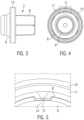
- the flow restricting orifice shown in Fig. 1 is a plastic component formed in one piece by injection molding.
- the flow restricting orifice 2 comprises a tubular nozzle 4 having a passage which reduces the cross-section of a mouth of a tube connector and which in this manner restricts the flow depending on the cross-sectional area of the passage of the tubular nozzle 4.
- Several flow restricting orifices 2 of different sizes are provided which have the same outer dimensions to fit into a mouth of a tube connector and which have a range of different inner dimensions to provide a range of different cross-sectional areas corresponding to a range of degrees of flow restrictions.
- the flow restricting orifice shown in Figs. 1 to 5 comprises an insertion portion 6 provided for insertion into a mouth of a tube connector.
- the outer wall of the insertion portion may, as shown in Figs. 1 to 3 , comprise ribs extending in axial direction of the insertion portion 6.
- Such ribs on the outer wall of the insertion portion 6 are provided for ensuring a tightly fitting seat of the insertion portion 6 in a mouth of a tube connector and may compensate tolerances of the outer diameter of the insertion portion, namely a certain deviation to a lower outer diameter of the insertion portion compared to the inner diameter of a mouth of a tube connector.
- This outer end portion 8 comprises a radially projecting, circumferentially extending shoulder for limiting movement of the flow restricting orifice 2 into a mouth of a tube connector.
- the flow restricting orifice 2 further comprises a coloured element 10 which radially extends beyond the outer surfaces of the tubular nozzle 4, in this case a coloured ring element 10 surrounding the tubular nozzle at a greater radius then the tubular nozzle 4.
- the coloured ring element 10 is connected to the outer end portion 8 of the tubular nozzle 4 by a frangible connection 12 which can be seen best in Figs. 4 and 5 .
- the frangible connection 12 is formed by a number of radially extending connecting webs which extend from the coloured ring element 10 in radial direction inwardly to the outer end portion 8, thereby connecting the coloured ring element 10 to the outer end portion 8 of the tubular nozzle.
- a coloured element 10 which radially extends beyond the outer surfaces of the tubular nozzle 4, in this case a coloured ring element 10 surrounding the tubular nozzle at a greater radius then the tubular nozzle 4.
- the coloured ring element 10 is connected to the outer end portion 8 of the tubular
- the frangible connection 12 of the coloured ring element 10 comprises six connecting webs which are connecting the coloured ring element 10 to the outer end portion 8 of the tubular nozzle 4 and which are arranged circumferentially distributed around the circumference of the coloured ring element 10.
- the connecting webs of the frangible connection 12 have a decreasing width which decreases from the outer ring element 10 towards the outer end portion 8 of the tubular nozzle 4.
- the connecting webs of the frangible connection 12 have the lowest width at the point of connection to the outer end portion 8. This portion of lowest width of the connecting webs is the weakest portion and therefore forms the predetermined breaking point having a rated breaking strength.
- the coloured ring element 10 comprises a radially inwardly projecting, circumferentially extending protrusion 11. As will be explained further below this inwardly projecting protrusion 11 permits that the ring element 10 may be pushed forward by a front end portion of a tube that is inserted into the opening of the coloured ring element 10.
- the connecting webs of the frangible connection 12 extend between the inner surface of the protrusion 11 of the coloured ring element 10 and the outer surface of the outer end portion 8 of the tubular nozzle 4.
- a tube connector 30 which comprises a tubular end portion comprising a so called fir-tree structure on the surface which is designed to hold a tube, for example a plastic tube, that has been pushed onto the tubular fir-tree portion of the tube connector 30.
- a flow restricting orifice 2 has already been inserted with its insertion portion into a mouth of the tube connector 30.
- a tube 40 is advanced towards the tube connector 30 and is introduced into the annular gap between the outer end portion 8 of the tubular nozzle 4 and the coloured ring element 10, as shown in Figs. 7 and 11 .
- the tube 40 its front end comes into abutment against the connecting webs of the frangible connection 12 and against the circumferential protrusion 11 of the coloured ring element 10.
- the front end of the tube 40 exerts force on the coloured ring element 10 and its frangible connection 12 to the outer end portion 8 of the tubular nozzle 4.
- the frangible connection 12 breaks, thus releasing the coloured ring element 10 and permitting the coloured ring element to follow the forward movement of the tube being pushed onto the tube connector 30.
- the front end of the slightly expanded tube pushes the coloured ring element 10 ahead, wherein the front end face of the tube abuts against the protrusion 11 of the coloured ring element 10.
- the tube 40 is slightly expanded when it is pushed onto the fir-tree portion 32 of the tube connector.
- the coloured ring element 10 remains as a visible indicator after tube 40 has been connected to the tube connector 30.
- This visible indicator permits a simple visual check whether a flow restricting orifice is present in the tube connector and which size the flow restricting orifice in the connected tube has, i.e. which degree of flow restriction is provided by the particular flow restricting orifice which is indicated by the colour of the coloured ring element.
- the coloured ring element 10 is configured to be retained extending around the front end portion of the connected tube and around the tube connector.
- the coloured ring element is a closed ring that is by its closed shape prevented from falling off.
- other designs of the coloured ring element 10 are possible, for example an open ring element with a circumferential gap that extends more than 180° around the circumference of the tube connected to the tube connector.
- other designs of coloured elements, other than rings or rings elements are possible as long as the coloured element is provided with shape features that are arranged to interact and engage with complementary shape feature on the tube or on the connector which ensures that the coloured element is retained by engagement of the shape features on assembly of the tube on the tube connector.
- the coloured element could have any other shape and include forwardly projecting pin or web that is guided and received in a bore of complementary cross-section formed in the collar of the tube connector for receiving the pin for retaining the coloured element on the tube connector.
- Figs. 14 to 16 an alternative second embodiment of a flow restricting orifice 2' is illustrated.
- the flow restricting orifice 2' comprises a tubular nozzle of similar or identical design as the tubular nozzle 4 of the first embodiment shown in Figs. 1 to 5 .
- the second embodiment of Figs. 14 to 16 comprises a coloured ring element 10' that is formed as an axially extensive sleeve which axially projects beyond the outer end portion of the tubular nozzle 4.
- the coloured ring element 10' has the form of an axially extensive sleeve and has a larger axial extension than the tubular nozzle 4.
- the coloured ring element 10' At the end portion of the coloured ring element 10' overlapping with outer end portion of the tubular sleeve the coloured ring element 10' is provided with a radially inwardly projecting, circumferentially extending protrusion in a manner corresponding to the protrusion 11 shown in Figs. 2 , 4 and 5 of the first embodiment.
- frangible connection is of the same design as the frangible connection 12 shown in Figs. 4 and 5 for the first embodiment.
- the flow restricting orifice 2' of the second embodiment is preferably formed as a single piece by injection molding.
- openings 20 serve as windows to allow visual inspection whether a tube that is inserted into the opening of the sleeve eventually reaches the end position inside the coloured ring element and abuts with its front end against the circumferential protrusion of the coloured ring element, as will be further explained below.
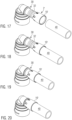
- Figs. 17 to 20 show in perspective views a sequence of steps when a tube 40 is connected to a tube connector 30 which is equipped with a flow restricting orifice 2', wherein the sequence of steps is shown in Figs. 21 to 24 in cross-sectional views.
- the tube connector 30 is of the same design as described in connection with Figs. 6 to 13 .
- the front end of the tube 40 at this stage approaches the inner wall of the coloured ring element 10' and its circumferential protrusion at the front end, thereby exerting radially directed and axially directed force on the coloured ring 10' element which causes the frangible connection to the outer end portion 8 of the tubular sleeve 4 to break.
- the coloured ring element 10' is then advanced together with the tube which is being pushed further onto the fir-tree portion 32 of the tube connector 30, as shown in Figs. 19 and 23 .
- Fig. 23 in the course of this movement the tube end being pushed on the fir-tree portion 32 of the tube connector 30 is slightly expanded which also causes a slight radial expansion of the coloured ring element 10'. The effect of this expansion will be discussed further below.
- the tube 40 is then further pushed to move axially onto the tube connector, until it reaches its connected end position as shown in Figs. 20 and 24 . In this end position the inwardly projecting protrusion at the front end of the coloured ring element 10' is engaged between the front end of the tube and a collar on the tube connector.
- One advantage of the second embodiment with the coloured ring element 10' as an axially extensive sleeve is that the coloured ring element 10' by its size has enhanced visibility and therefore makes visual inspection very simple.
- a further advantageous effect of the flow restricting orifice 2' of the second embodiment is a further function of the coloured ring element 10' in the form of an axially extensive sleeve.
- This function is also referred to as wedding-band function of the sleeve of the coloured ring element 10' which embraces and engages the tube end portion around the tube connector and which thereby increases the burst strength of the connection of the tube 40 on the tube connector 30.
- the engagement of the coloured ring element 10' on the outer wall of the tube 40 is enhanced when the tube portion that is pushed onto the fir-tree portion 32 of the tube connector 30 is expanded and urged against the inner wall of the coloured ring element 10', thereby also expanding the coloured ring element 10' which causes a tight engagement of the coloured ring element 10' around the front end portion of the tube in its connected position.
Landscapes
- Engineering & Computer Science (AREA)
- General Engineering & Computer Science (AREA)
- Mechanical Engineering (AREA)
- Life Sciences & Earth Sciences (AREA)
- Sustainable Development (AREA)
- Sustainable Energy (AREA)
- Power Engineering (AREA)
- Transportation (AREA)
- Physics & Mathematics (AREA)
- Fluid Mechanics (AREA)
- Quick-Acting Or Multi-Walled Pipe Joints (AREA)
Description
- The present invention is directed to an assembly of a tube connector and a flow restricting orifice fitted into a mouth of the tube connector. A flow restricting orifice is a nozzle insert for reducing the cross-section to thereby restrict the flow to a desired degree.
- In the automotive industry flow restricting orifices are for example used in connection with cooling of batteries or cooling of different portions of a single battery of an electrically driven vehicle. Normally a single source of cooling fluid is available in a vehicle. For several regions where cooling is required several tube connectors are provided which are supplied with cooling fluid from the cooling fluid source and which transfer cooling fluid via tubes connected thereto to the individual regions. Since each region to be cooled may need a different degree of cooling, i.e. some regions of the battery may generate more heat than others during charging of the battery, the amount of cooling provided by cooling fluid flowing through each individual tube has to be set for each individual tube. This is done by providing a set of flow restricting orifices, the flow restricting orifices offering a range of sizes and accordingly provide different degrees of flow restriction. A flow restricting orifice in the form of a tubular nozzle of reduced diameter is selected for each tube connector according to the flow restriction needed and is inserted into the mouth of the tube connector.
- A flow restricting orifice of this kind is for example described in
DE 10 2013 113 813 A1 - Currently the size of the flow restricting orifice, or in other words the degree of flow restriction provided by the flow restricting orifice, is indicated by a colour marking for each size type of flow restricting orifices. In other words the colour of the flow restricting orifice is a code for the degree of flow restriction provided by a particular orifice. In this manner an operator can pick a particular flow restricting orifice out of a set of such orifices by selecting the desired colour orifice and insert it to a mouth of a particular tube connector to which thereafter a tube is to be connected by pushing it onto the tube connector. However, after the tube has been connected to the tube connector the flow restricting orifice is no longer visible. Therefore, after the tubes have been mounted to the tube connectors it is no longer possible to check whether each of the connectors has been provided with a flow restricting orifice, and whether the correct size flow restricting orifice for each particular tube connector has been mounted. This is in particular disadvantageous because after an operator had the task to mount a number of different flow restricting orifices to a number of tube connectors and to connect tubes to the tube connectors, it may occur that uncertainties arise whether each tube connector has been equipped with the desired flow restricting orifice.
-
US 2016/208751 A9 discloses a quick connector for a tube having an insert portion to be received in the tube. If it would be contemplated to use this quick connector as a flow restricting orifice for a tube connector this quick connector comprises a tubular nozzle having an insert portion, and a visible marking comprising a marking element which extends radially outwardly from the tubular nozzle and which includes a frangible connection which is connected to the tubular nozzle and which has at least one predetermined breaking point, the frangible connection being configured to release the marking element when the frangible connection is broken before a tube is completely pushed onto the tube connector, the marking element being configured to be retained on the tube connector or on the tube connected to the tube connector to remain, after the tube has been connected to the tube connector, as a marking element visible from the exterior. - It is an object of the present invention to provide an assembly of a flow restricting orifice and of a tube connector which allows to visually check whether a flow restricting orifice has been mounted in the mouth of the tube connector after the tube has been connected to the tube connector. Preferably, if there is more than one size of a flow restricting orifice, it would be desirable to be able to check which type (size) of flow restricting orifice has been mounted in the mouth of a tube connector after the tube has been connected to the tube connector.
- In addition it is an object of the present invention to define a method for connecting a tube to the tube connector of the assembly of the tube connector and the flow restricting orifice, which method after it has been carried out allows to check whether and which type of flow resisting orifice is mounted in the tube connector.
- The present invention provides an assembly according to
claim 1 of a tube connector and of a flow restriction orifice for the tube connector, wherein the flow restricting orifice comprises a tubular nozzle having an insert portion for insertion into a mouth of the tube connector to restrict the flow through the mouth of the tube connector. The flow restricting orifice is provided with a visible marking comprising a marking element which extends radially outwardly from the tubular nozzle and which includes a frangible connection connected to the tubular nozzle. This frangible connection has a predetermined breaking point configured to release the marking element when the frangible connection is broken before a tube is completely pushed on the tube connector. The visible element is configured to remain engaged or retained on the tube connector or on a tube connected to the tube connector, to thereby remain, after a tube has been connected to the tube connector, as a marking element configured to be visually perceivable from the exterior of the tube, wherein the flow restricting orifice is fitted in the mouth of the tube connector. By means of such retained visible part of the flow restricting orifice outside of a tube connected to the tube connector it is possible to visually check whether a flow restricting orifice has been mounted in the mouth of the tube connector although the mouth of the tube connector is no longer visible when the tube has been connected. - In case there is only one type of flow restricting orifice the marking element needs to be visible only but does not need to carry any further information. In case there is more than one type (size) of flow restricting orifice the marking element should be indicative for the type of flow restricting orifice, for example by its size, shape, graphical symbols, characters, numbers or colour. In a preferred embodiment the marking element is a coloured marking element with a colour that is representative for the type flow restricting orifice.
- The flow restricting orifice allows to separate the visible marking in the form of a marking element in the course of the assembly of the flow restricting orifice to the tube connector and connecting the tube to the tube connector, wherein the marking element is configured to remain linked to the assembly of tube connector and tube after the tube has been connected to thereby serve as a visible marking. This allows to check whether a flow restricting orifice has been placed in the mouth of the tube connector before the tube has been connected; in this case the marking element is a marker that a flow restricting orifice has been mounted. In case of more than one type of flow restricting orifices this also allows to check by a particular code of the marking element which type of flow restricting orifice has been mounted. As indicated above the code carried by the marking element could be its size, shape, graphical symbols, characters, numbers or colour.
- As far as reference is made herein to a "visible" marking or indicator which allows "visual" inspection, this does not imply that a human operator is necessarily required to visually inspect the tubes connected to the tube connectors; the visual check can also be performed with a camera connected to a control unit (computer) which is programmed to perform pattern recognition to check for the presence of the marking element as a final check of tubes connected to tube connectors for the presence of the desired flow restricting orifice. In case the marking element carries information on the type (size) of flow restricting orifice the visual recognition program is arranged to identify the coded information, for example to identify the colour of the marking element.
- In a preferred embodiment of the assembly the marking element is a visible ring element which surrounds the tubular nozzle and which circumferentially extends at least 180° around the tubular nozzle. This shape of the marking element including a ring or a ring segment permits that the visible ring element remains retained around a tube connector or a tube connected to the tube connector, i.e. retained by embracing at least partly the circumference of a tube connector in front of a connected tube and/or the circumference of a front end portion of the tube.
- In a preferred embodiment of the assembly the tubular nozzle of the flow restricting orifice comprises an outer end portion adjoining the insert portion, wherein the outer end portion has a circumferential shoulder for limiting movement of the tubular nozzle into a mouth of a tube connector. In this case the frangible connection is connected to the outer end portion of the tubular nozzle so that the insertion portion the flow restricting orifice can be inserted into a mouth of a tube connector without affecting the frangible connection. Preferably, the outer end portion has at its outer end facing away from the insertion portion a tapering end portion so that the outer diameter is lowest at the end of the outer end portion remote from the insertion portion. This design assists in guiding a tube when the outer end portion is inserted into a mouth of the tube. Preferably also the circumferential shoulder has a tapering shape such that the shoulder has the largest outer diameter at the end of the outer end portion which adjoins the insertion portion. This largest outer diameter is preferably larger than the inner diameter of a tube that is to be connected to a tube connector being equipped with the flow restricting orifice. If this largest outer diameter of the shoulder of the outer end portion has a diameter that is larger than the inner diameter of the associated tube this will prevent that the orifice might be blown out of the mouth of the tube connector and into the tube due to fluid flow out of the tube connector.
- According to a preferred embodiment of the assembly the predetermined breaking point of the frangible connection is, in radial direction of the tubular nozzle, located closer to the tubular nozzle than to the surrounding marking element. This arrangement ensures that, after the frangible connection has been broken, a radially inwardly projecting portion of the frangible connection remains on the marking element. Such inwardly projecting remaining portion of the frangible connection allows the marking element to be pushed forward by a component pushing against the remaining portion of the breakage connection. In particular, it is preferred that the frangible connection is, in radial direction of the tubular nozzle, located closer to the the tubular nozzle than to the surrounding marking element.
- In a preferred embodiment of the assembly the frangible connection is formed by one or more connecting webs radially inwardly extending from the marking element and being connected to the tubular nozzle. The one or more connecting webs have a predetermined breakaging strength. Preferrably, the connecting web(s) extend(s) from the marking ring element. Preferrably, the connecting web(s) is (are) connected to an outer end portion of the tubular nozzle adjacent to the insertion portion and having an outwardly projecting shoulder for limiting movement of the tubular nozzle into a mouth of a tube connector. Preferably, several connecting webs are provided which are arranged circumferentially distributed around the outer end portion of the tubular nozzle. Preferably, the width of the one or more radially extending connecting webs is decreasing from the marking ring element towards the outer end portion of the tubular nozzle. In this case the predetermined breaking point is in the area of the lowest width of the one or more connecting webs.
- In a preferred embodiment of the assembly the flow restricting orifice the visible marking is a colour marking and the marking element is a coloured element.
- In a preferred embodiment of the assembly the marking ring element is a closed ring completely surrounding the circumference of the tubular nozzle. Alternatively the marking ring element is an open ring element including a circumferential gap. The latter design allows the tubular ring element to be elastically expanded by opening the gap further to fit around larger radii.
- In a preferred embodiment of the assembly the visible marking further comprises a visible flag connected to the marking ring element to increase the area of the visible marking to enhance its visibility. Such arrangement is in particular useful for embodiments in which the marking ring element is relatively thin, i.e. has a low axial extension along the axial direction of the tubular nozzle.
- In a preferred embodiment of the assembly the frangible connection is configured to break upon a tube being pushed onto a tube connector, and the marking element is configured to be capable of being pushed onto a tube connector by a front end of a tube being pushed onto a tube connector. In this embodiment breaking of the frangible connection and moving the released marking element forward is automatically achieved by moving a tube onto the tube connector to connect it thereto, wherein the marking element is automatically retained on the tube connector in front of the tube or around a tube end portion.
- In a preferred embodiment of the assembly the marking ring element is formed as an axially extending cylindrical sleeve having an axial length that is larger than half of its outer diameter. In such embodiments the marking ring element in the form of an axially extending cylindrical sleeve can have the function of a so called wedding-band, i.e. it can embrace the front end portion of the tube on the tube connector, thereby increasing the burst strength of the connection of the tube on the tube connector.
- In a preferred embodiment of this kind the cylindrical sleeve comprises at least one opening in its outer wall close to its leading end which is leading when it is pushed onto the tube connector by an advancing tube to be connected thereto, wherein the at least one opening is configured to serve as a window to allow visual inspection whether the tube has reached the region within the sleeve in which the at least one opening is located.
- In a preferred embodiment of the assembly the tubular nozzle, the visible marking including the marking element and the frangible connection connected to the tubular nozzle are formed as an integral part in one piece, optionally wherein the flow restricting orifice is an injection molded plastic part.
- The present invention is further directed to a method according to claim 15, for connecting a tube to the tube connector of an assembly as defined in any of claims 1 - 14. This method comprises the steps:
- providing the assembly according to any of the claims 1 - 14,
- breaking the frangible connection to release the marking element and moving it further along the tube connector,
- pushing the tube onto the tube connector to connect it to the tube connector, the marking element remaining as a visible indicator retained around an end portion of the tube connector in front of the connected tube or around a front end portion of the tube.
- The sequence of the steps of this method does not define a temporal order. For example the step of inserting the insert portion of the flow restricting orifice into a mouth of the tube connector, thereby providing the assembly of tube connector and flow restricting orifice, and the steps of breaking the frangible connection and pushing the tube onto the tube connector can take place simultaneously, for example if the flow restricting orifice is first attached to the front end of a tube, whereafter the tube is pushed towards the tube connector, thereby introducing the insert portion of the flow restricting orifice in the mouth of the tube connector to provide the assembly, breaking the frangible connection by pushing the tube further forward, thereby also moving the marking element to move further onto the tube connector to retained there is a visible indicator.
- In a preferred embodiment the insert portion of the tubular nozzle is first inserted into the mouth of the tube connector, whereafter the frangible connection is broken by pushing a tube onto the tube connector such that a front end of the tube pushes against the marking element causing the frangible connection to break and to move the marking element forward by advancing the tube until the tube reaches its connected position on the tube connector, thereby leaving the marking element retained on the tube connector or on a front end portion of the tube.
- Alternatively, it is also possible to first mount the flow restricting orifice in a mouth of a tube connector, then to break the breakage connection, either manually or using a tool, and then in a separate further step to push a tube onto the tube connector to connect it thereto.
- The present invention will be described in the following with reference to embodiments illustrated in the drawings in which:
-
Fig. 1 shows a perspective view of a first embodiment of a flow restricting orifice; -
Fig. 2 shows perspective views of the flow restricting orifice ofFig. 1 , wherein a coloured ring element has been separated from a tubular nozzle of the flow restricting orifice by breaking the frangible connection between them; -
Fig. 3 shows a side view of the flow restricting orifice ofFig. 1 ; -
Fig. 4 shows an inner end view of the flow restricting orifice ofFig. 1 , looking at an insertion portion of the flow restricting orifice; -
Fig. 5 is a detail ofFig. 4 , showing a connecting web as part of a frangible connection of the flow restricting orifice; -
Figs. 6 to 9 show a sequence of states when a tube is connected to a tube connector which is equipped with the flow restricting orifice ofFig. 1 ; -
Figs. 10 to 13 show cross-sectional views of the sequence of states when the tube is connected to the tube connector which is equipped with a flow restricting orifice ofFig. 1 ; -
Fig. 14 shows perspective views of a second embodiment of a flow restricting orifice; -
Fig. 15 shows a side view of the flow restricting orifice ofFig. 14 ; -
Fig. 16 shows an inner end view of the flow restricting orifice ofFig. 14 , looking at the inner end of the insertion portion of the flow restricting orifice ofFig. 14 ; -
Figs. 17 to 20 show a sequence of states when a tube is connected to a tube connector which is equipped with a flow restricting orifice ofFig. 14 ; -
Figs. 21 to 24 show cross-sectional views of the sequence of states when the tube is connected to the tube connector which is equipped with the flow restricting orifice ofFig. 14 . - In the following two embodiments of the present invention will be described, wherein
Figs. 1 to 13 show a first embodiment andFigs. 14 to 24 show a second embodiment. In both embodiments the visible marking is assumed to be a colour marking, so that the marking element is a coloured marking element which will be referred to as "coloured element" for short, and the marking ring element is a coloured marking ring element which will be referred to as "couloured ring element" for short in the following description. However, it should be kept in mind that other marking types are possible such as size or shape of the marking element, graphical symbols, characters or numbers carried by the marking element etc.. - The flow restricting orifice shown in
Fig. 1 is a plastic component formed in one piece by injection molding. Theflow restricting orifice 2 comprises atubular nozzle 4 having a passage which reduces the cross-section of a mouth of a tube connector and which in this manner restricts the flow depending on the cross-sectional area of the passage of thetubular nozzle 4. Severalflow restricting orifices 2 of different sizes are provided which have the same outer dimensions to fit into a mouth of a tube connector and which have a range of different inner dimensions to provide a range of different cross-sectional areas corresponding to a range of degrees of flow restrictions. - The flow restricting orifice shown in
Figs. 1 to 5 comprises aninsertion portion 6 provided for insertion into a mouth of a tube connector. The outer wall of the insertion portion may, as shown inFigs. 1 to 3 , comprise ribs extending in axial direction of theinsertion portion 6. Such ribs on the outer wall of theinsertion portion 6 are provided for ensuring a tightly fitting seat of theinsertion portion 6 in a mouth of a tube connector and may compensate tolerances of the outer diameter of the insertion portion, namely a certain deviation to a lower outer diameter of the insertion portion compared to the inner diameter of a mouth of a tube connector. - Axially adjacent to the
insertion portion 6 anouter end portion 8 of thetubular nozzle 4 is provided. Thisouter end portion 8 comprises a radially projecting, circumferentially extending shoulder for limiting movement of theflow restricting orifice 2 into a mouth of a tube connector. - The
flow restricting orifice 2 further comprises acoloured element 10 which radially extends beyond the outer surfaces of thetubular nozzle 4, in this case acoloured ring element 10 surrounding the tubular nozzle at a greater radius then thetubular nozzle 4. Thecoloured ring element 10 is connected to theouter end portion 8 of thetubular nozzle 4 by afrangible connection 12 which can be seen best inFigs. 4 and 5 . Thefrangible connection 12 is formed by a number of radially extending connecting webs which extend from thecoloured ring element 10 in radial direction inwardly to theouter end portion 8, thereby connecting thecoloured ring element 10 to theouter end portion 8 of the tubular nozzle. In the embodiment shown inFig. 4 thefrangible connection 12 of thecoloured ring element 10 comprises six connecting webs which are connecting thecoloured ring element 10 to theouter end portion 8 of thetubular nozzle 4 and which are arranged circumferentially distributed around the circumference of thecoloured ring element 10. As can be seen inFig. 5 the connecting webs of thefrangible connection 12 have a decreasing width which decreases from theouter ring element 10 towards theouter end portion 8 of thetubular nozzle 4. The connecting webs of thefrangible connection 12 have the lowest width at the point of connection to theouter end portion 8. This portion of lowest width of the connecting webs is the weakest portion and therefore forms the predetermined breaking point having a rated breaking strength. - As can be seen in the view of the
coloured ring element 10 inFig. 2 , thecoloured ring element 10 comprises a radially inwardly projecting, circumferentially extendingprotrusion 11. As will be explained further below this inwardly projectingprotrusion 11 permits that thering element 10 may be pushed forward by a front end portion of a tube that is inserted into the opening of thecoloured ring element 10. - As can be seen in
Figs. 4 and 5 the connecting webs of thefrangible connection 12 extend between the inner surface of theprotrusion 11 of thecoloured ring element 10 and the outer surface of theouter end portion 8 of thetubular nozzle 4. - It will now be described how the
flow restricting orifice 2 ofFigs. 1 to 5 is applied when a tube is to be connected to a tube connector. In this respect reference is made to the sequence of process steps shown in perspective view inFigs. 6 to 9 and in cross-sectional view inFigs. 10 to 14 . In this example atube connector 30 is shown which comprises a tubular end portion comprising a so called fir-tree structure on the surface which is designed to hold a tube, for example a plastic tube, that has been pushed onto the tubular fir-tree portion of thetube connector 30. InFig. 6 aflow restricting orifice 2 has already been inserted with its insertion portion into a mouth of thetube connector 30. - Then a
tube 40 is advanced towards thetube connector 30 and is introduced into the annular gap between theouter end portion 8 of thetubular nozzle 4 and thecoloured ring element 10, as shown inFigs. 7 and11 . In the course of advancing thetube 40 its front end comes into abutment against the connecting webs of thefrangible connection 12 and against thecircumferential protrusion 11 of thecoloured ring element 10. When pushing thetube 40 further onto the tube connector the front end of thetube 40 exerts force on thecoloured ring element 10 and itsfrangible connection 12 to theouter end portion 8 of thetubular nozzle 4. Since thetubular nozzle 4 cannot move further into the mouth of thetube connector 30 in response to such force thefrangible connection 12 breaks, thus releasing thecoloured ring element 10 and permitting the coloured ring element to follow the forward movement of the tube being pushed onto thetube connector 30. As can be seen inFig. 8 andFig. 12 the front end of the slightly expanded tube pushes thecoloured ring element 10 ahead, wherein the front end face of the tube abuts against theprotrusion 11 of thecoloured ring element 10. Thetube 40 is slightly expanded when it is pushed onto the fir-tree portion 32 of the tube connector. - Eventually the tube reaches its connected position in which the
protrusion 11 of the coloured ring element is pressed against a circumferential collar of the tube connector, as can be seen inFigs. 9 and13 . - In this manner the
coloured ring element 10 remains as a visible indicator aftertube 40 has been connected to thetube connector 30. This visible indicator permits a simple visual check whether a flow restricting orifice is present in the tube connector and which size the flow restricting orifice in the connected tube has, i.e. which degree of flow restriction is provided by the particular flow restricting orifice which is indicated by the colour of the coloured ring element. - The
coloured ring element 10 is configured to be retained extending around the front end portion of the connected tube and around the tube connector. In the illustrated embodiment the coloured ring element is a closed ring that is by its closed shape prevented from falling off. In principle, also other designs of thecoloured ring element 10 are possible, for example an open ring element with a circumferential gap that extends more than 180° around the circumference of the tube connected to the tube connector. In principle also other designs of coloured elements, other than rings or rings elements, are possible as long as the coloured element is provided with shape features that are arranged to interact and engage with complementary shape feature on the tube or on the connector which ensures that the coloured element is retained by engagement of the shape features on assembly of the tube on the tube connector. For example, the coloured element could have any other shape and include forwardly projecting pin or web that is guided and received in a bore of complementary cross-section formed in the collar of the tube connector for receiving the pin for retaining the coloured element on the tube connector. - In
Figs. 14 to 16 an alternative second embodiment of a flow restricting orifice 2' is illustrated. The flow restricting orifice 2' comprises a tubular nozzle of similar or identical design as thetubular nozzle 4 of the first embodiment shown inFigs. 1 to 5 . In contrast to the first embodiment the second embodiment ofFigs. 14 to 16 comprises a coloured ring element 10' that is formed as an axially extensive sleeve which axially projects beyond the outer end portion of thetubular nozzle 4. In the illustrated second embodiment the coloured ring element 10' has the form of an axially extensive sleeve and has a larger axial extension than thetubular nozzle 4. At the end portion of the coloured ring element 10' overlapping with outer end portion of the tubular sleeve the coloured ring element 10' is provided with a radially inwardly projecting, circumferentially extending protrusion in a manner corresponding to theprotrusion 11 shown inFigs. 2 ,4 and 5 of the first embodiment. - Also the frangible connection is of the same design as the
frangible connection 12 shown inFigs. 4 and 5 for the first embodiment. The flow restricting orifice 2' of the second embodiment is preferably formed as a single piece by injection molding. - At the end of the sleeve of the coloured ring element 10' overlapping with the tubular nozzle the wall of the sleeve is provided with
openings 20 which serve as windows to allow visual inspection whether a tube that is inserted into the opening of the sleeve eventually reaches the end position inside the coloured ring element and abuts with its front end against the circumferential protrusion of the coloured ring element, as will be further explained below. -
Figs. 17 to 20 show in perspective views a sequence of steps when atube 40 is connected to atube connector 30 which is equipped with a flow restricting orifice 2', wherein the sequence of steps is shown inFigs. 21 to 24 in cross-sectional views. Thetube connector 30 is of the same design as described in connection withFigs. 6 to 13 . - In
Fig. 17 the flow restricting orifice 2' has been inserted with itsinsertion portion 6 into a mouth of thetube connector 30, and thetube 40 is advanced to be inserted into the opening of the coloured ring element 10' as shown inFig. 18 . - As shown in
Fig. 22 the front end of thetube 40 at this stage approaches the inner wall of the coloured ring element 10' and its circumferential protrusion at the front end, thereby exerting radially directed and axially directed force on the coloured ring 10' element which causes the frangible connection to theouter end portion 8 of thetubular sleeve 4 to break. - The coloured ring element 10' is then advanced together with the tube which is being pushed further onto the fir-
tree portion 32 of thetube connector 30, as shown inFigs. 19 and23 . As can be seen inFig. 23 in the course of this movement the tube end being pushed on the fir-tree portion 32 of thetube connector 30 is slightly expanded which also causes a slight radial expansion of the coloured ring element 10'. The effect of this expansion will be discussed further below. - The
tube 40 is then further pushed to move axially onto the tube connector, until it reaches its connected end position as shown inFigs. 20 and24 . In this end position the inwardly projecting protrusion at the front end of the coloured ring element 10' is engaged between the front end of the tube and a collar on the tube connector. - In this connected position of the tube on the tube connector the coloured ring element 10' again remains as a visible indicator that indicates, by its colour, the size (flow restriction capacity) of the
tubular nozzle 4 of the flow restrictor. - One advantage of the second embodiment with the coloured ring element 10' as an axially extensive sleeve is that the coloured ring element 10' by its size has enhanced visibility and therefore makes visual inspection very simple.
- A further advantageous effect of the flow restricting orifice 2' of the second embodiment is a further function of the coloured ring element 10' in the form of an axially extensive sleeve. This function is also referred to as wedding-band function of the sleeve of the coloured ring element 10' which embraces and engages the tube end portion around the tube connector and which thereby increases the burst strength of the connection of the
tube 40 on thetube connector 30. The engagement of the coloured ring element 10' on the outer wall of thetube 40 is enhanced when the tube portion that is pushed onto the fir-tree portion 32 of thetube connector 30 is expanded and urged against the inner wall of the coloured ring element 10', thereby also expanding the coloured ring element 10' which causes a tight engagement of the coloured ring element 10' around the front end portion of the tube in its connected position. - In the Figures and the description of the method for equipping a tube connector with a flow restricting orifice and for connecting a tube it was assumed that the
flow restricting orifice 2, 2' is first inserted with itsinsertion portion 6 into a mouth of thetube connector 30, whereafter the tube end portion is moved onto the fir-tree portion of thetube connector 30. However, it is also possible to first introduce the tube end portion of thetube 40 into thecoloured ring element 10, 10' of theflow restricting orifice 2, 2', and then to move the tube with theflow restricting orifice 2, 2' on its end portion towards the tube connector, to thereby introduce theinsert portion 6 of the flow restricting orifice into the mouth of the tube connector, thereby providing the claimed assembly, whereafter the tube is further pushed onto the fir-tree portion 32 of thetube connector 30, thereby breaking thefrangible connection 12 to release thecoloured ring element 10, 10' and to push it further onto the tube connector until thetube 40 reaches its connected position with the coloured ring element surrounding the front end portion of the tube or of the tube connector in front of the tube as a visible indicator.
Claims (16)
- Assembly of a tube connector (30) and a flow restricting orifice (2; 2'), said flow restricting orifice comprising a tubular nozzle (4) having an insert portion (6) for insertion into a mouth of the tube connector, wherein the flow restricting orifice (2; 2') is fitted in the mouth of the tube connector (30), wherein the flow restricting orifice (2; 2') comprises a visible marking comprising a marking element (10; 10') which extends radially outwardly from the tubular nozzle (4) and which includes a frangible connection (12) which is connected to the tubular nozzle and which has at least one predetermined breaking point (14), the frangible connection (12) being configured to release the marking element (10; 10') when the frangible connection (12) is broken before a tube is completely pushed onto the tube connector, the marking element (10; 10') being configured to be retained on the tube connector or on the tube connected to the tube connector, to remain, after the tube has been connected to the tube connector, as a marking element visible from the exterior of the tube.
- Assembly according to claim 1, characterized in that the marking element (10; 10') is a marking ring element (10; 10') which surrounds the tubular nozzle (4) and extends circumferentially at least 180° around the tubular nozzle.
- Assembly according to claim 1 or 2, characterized in that the tubular nozzle (4) comprises an outer end portion (8) adjoining the insert portion (6), which outer end portion (6) has a circumferential shoulder for limiting movement of the tubular nozzle (4) into a mouth of a tube connector, and in that the frangible connection (12) is connected to the outer end portion (8) of the tubular nozzle.
- Assembly according to any of the claims claim 1 - 3, characterized in that the predetermined breaking point (14) of the frangible connection (12) is in radial direction of the tubular nozzle located closer to the tubular nozzle (4) than to the surrounding marking element (10; 10').
- Assembly according to any of the preceding claims 1 - 4, characterized in that the frangible connection (12) is formed by one or more connecting webs radially extending from the marking element (10; 10') and being connected to the tubular nozzle (4), each of the one or more connecting webs having a predetermined breaking point (14) with rated breakage strength.
- Assembly according to claim 3, characterized in that width of the one or more radially extending connecting webs is decreasing from the marking element (10; 10') towards the outer end portion (8) of the tubular nozzle.
- Assembly according to one of the preceding claims, characterized in that the visible marking is a colour marking and the marking element is a coloured element.
- Assembly according to claim 2 and any of the claims 3 - 7, characterized in that the marking ring element (10; 10') is a closed ring surrounding the circumference of the tubular nozzle (4).
- Assembly according to claim 2 and any of the claims 3 - 7, characterized in that the marking ring element is an open ring element including a circumferential gap.
- Assembly according to claim 2 and any of the claims 3 - 9, characterized in that the visible marking further comprises a visible flag connected to the marking ring element (10; 10') to increase the area of the visible marking to enhance its visibility.
- Assembly according to any of the preceding claims, characterized in that the frangible connection (12) is configured to break upon a tube being pushed onto a tube connector, and in that the marking element is configured to be capable of being pushed onto a tube connector by a front end of a tube being pushed onto a tube connector.
- Assembly according claim 2 and any of the claims 3 - 11, characterized in that the marking ring element (10') is formed as an axially extending cylindrical sleeve having an axial length that is larger than half of its outer diameter.
- Assembly according to claim 12, characterized in that the cylindrical sleeve comprises at least one opening (20) in its outer wall close to its leading end which is leading when it is pushed onto the tube connector by an advancing tube to be connected thereto, the at least one opening (20) being configured to serve as a window to allow visual inspection whether the tube has reached the region of the sleeve in which the at least one opening is located.
- Assembly according to any of the preceeding claims, characterized in that the tubular nozzle (4), the visible marking including the marking element and the frangible connection (12) connected to the tubular nozzle (4) are formed as an integral part in one piece, optionally wherein the flow restricting orifice is an injection molded plastic part.
- Method for equipping a tube connector (30) with a flow restricting orifice (2; 2') and for connecting a tube (40) to the tube connector (30) equipped with the flow restricting orifice (2; 2'), the method comprising the steps:providing the assembly according to any of the claims 1 - 14, whereby the insert portion (6) of the flow restricting orifice (2; 2') is inserted into the mouth of the tube connector (30),breaking the frangible connection (12) to release the marking element and moving it further along the tube connector (30),pushing the tube (40) onto the tube connector (30) to connect it to the tube connector (30), the marking element remaining as a visible indictor retained at an end portion of the tube connector (30) in front of the connected tube (40) or at a front end portion of the tube (40).
- Method according to claim 15, characterized in that the insert portion (6) of the tubular nozzle (4) is first inserted into the mouth of the tube connector (30), whereafter the frangible connection (12) is broken by pushing the tube (40) onto the tube connector (30) such that a front end of the tube (40) pushes against the marking element causing the frangible connection (12) to break and moving the marking element forward by the advancing tube (40) until the tube (40) reaches its connected position on the tube connector (30).
Applications Claiming Priority (1)
| Application Number | Priority Date | Filing Date | Title |
|---|---|---|---|
| PCT/EP2021/060345 WO2022223106A1 (en) | 2021-04-21 | 2021-04-21 | Flow restricting orifice |
Publications (3)
| Publication Number | Publication Date |
|---|---|
| EP4165334A1 EP4165334A1 (en) | 2023-04-19 |
| EP4165334C0 EP4165334C0 (en) | 2024-09-11 |
| EP4165334B1 true EP4165334B1 (en) | 2024-09-11 |
Family
ID=75674797
Family Applications (1)
| Application Number | Title | Priority Date | Filing Date |
|---|---|---|---|
| EP21721435.2A Active EP4165334B1 (en) | 2021-04-21 | 2021-04-21 | Assembly with a flow restricting orifice |
Country Status (3)
| Country | Link |
|---|---|
| US (1) | US12305676B2 (en) |
| EP (1) | EP4165334B1 (en) |
| WO (1) | WO2022223106A1 (en) |
Family Cites Families (6)
| Publication number | Priority date | Publication date | Assignee | Title |
|---|---|---|---|---|
| GB2242281A (en) * | 1990-03-21 | 1991-09-25 | Ford Motor Co | Security test device |
| FR2830071B1 (en) * | 2001-09-21 | 2003-11-14 | Legris Sa | INSTANT CONNECTION DEVICE |
| US7922213B2 (en) * | 2003-10-17 | 2011-04-12 | Twin Bay Medical, Inc. | Barb clamp with smooth bore |
| FR2863032B1 (en) * | 2003-12-02 | 2006-01-13 | Comap | CRIMPING FITTING FOR MULTILAYER TUBES |
| ES2548185T3 (en) * | 2012-11-28 | 2015-10-14 | TI Automotive (Fuldabrück) GmbH | Car unit and procedure for the manufacture of a car unit |
| DE102013113813A1 (en) | 2013-12-11 | 2015-06-11 | Dr. Ing. H.C. F. Porsche Aktiengesellschaft | Connector for connecting a media-carrying fluid line of a motor vehicle |
-
2021
- 2021-04-21 US US18/555,073 patent/US12305676B2/en active Active
- 2021-04-21 WO PCT/EP2021/060345 patent/WO2022223106A1/en not_active Ceased
- 2021-04-21 EP EP21721435.2A patent/EP4165334B1/en active Active
Also Published As
| Publication number | Publication date |
|---|---|
| US20240191732A1 (en) | 2024-06-13 |
| EP4165334C0 (en) | 2024-09-11 |
| US12305676B2 (en) | 2025-05-20 |
| WO2022223106A1 (en) | 2022-10-27 |
| EP4165334A1 (en) | 2023-04-19 |
Similar Documents
| Publication | Publication Date | Title |
|---|---|---|
| CN100526700C (en) | Tensile plug connector | |
| CA2146253C (en) | Positive transition quick connect piping | |
| US4979765A (en) | Swivelable quick connector assembly | |
| US7467813B2 (en) | Quick connector | |
| EP0308160B1 (en) | Tube connector with indicator and release | |
| KR920006386B1 (en) | Pipe connector | |
| US7891380B2 (en) | Protective cap for quick connector | |
| CN110131509B (en) | Fluid connection device | |
| EP0727027B1 (en) | Quick connector with integral release member | |
| EP2976564B1 (en) | Locking quick connect assembly | |
| CN214331850U (en) | Coupling device for tubular elements | |
| US20160245441A1 (en) | Connector, releasing tool, set comprising connector and releasing tool | |
| US20170114935A1 (en) | Fluid connector with full insertion assurance cap disconnect tool | |
| US20060170211A1 (en) | Quick connector | |
| GB2180313A (en) | A releasable plug-in joint | |
| CN106369232B (en) | Vehicle part and motor vehicle | |
| EP3290769B1 (en) | Fitting for connecting to a tubular element, tubing connection and a method for connecting a fitting to a tubular element | |
| CN101210638A (en) | Joint for resin pipe | |
| PL194426B1 (en) | Pipe fitting | |
| EP4165334B1 (en) | Assembly with a flow restricting orifice | |
| EP1596118B1 (en) | Dustproof cap for quick connector and quick connector | |
| US5431454A (en) | Quick connection | |
| US12331774B2 (en) | Coupling bolt of a plug-in coupling, first component with the coupling bolt, associated plug-in coupling and connecting structure of two components | |
| EP1070899B1 (en) | Connecting structure | |
| EP2304295B1 (en) | Plug-in hose coupling |
Legal Events
| Date | Code | Title | Description |
|---|---|---|---|
| STAA | Information on the status of an ep patent application or granted ep patent |
Free format text: STATUS: UNKNOWN |
|
| STAA | Information on the status of an ep patent application or granted ep patent |
Free format text: STATUS: THE INTERNATIONAL PUBLICATION HAS BEEN MADE |
|
| PUAI | Public reference made under article 153(3) epc to a published international application that has entered the european phase |
Free format text: ORIGINAL CODE: 0009012 |
|
| STAA | Information on the status of an ep patent application or granted ep patent |
Free format text: STATUS: REQUEST FOR EXAMINATION WAS MADE |
|
| 17P | Request for examination filed |
Effective date: 20230116 |
|
| AK | Designated contracting states |
Kind code of ref document: A1 Designated state(s): AL AT BE BG CH CY CZ DE DK EE ES FI FR GB GR HR HU IE IS IT LI LT LU LV MC MK MT NL NO PL PT RO RS SE SI SK SM TR |
|
| GRAP | Despatch of communication of intention to grant a patent |
Free format text: ORIGINAL CODE: EPIDOSNIGR1 |
|
| STAA | Information on the status of an ep patent application or granted ep patent |
Free format text: STATUS: GRANT OF PATENT IS INTENDED |
|
| RIC1 | Information provided on ipc code assigned before grant |
Ipc: F01P 7/14 20060101ALN20240411BHEP Ipc: B60K 1/00 20060101ALN20240411BHEP Ipc: B60K 11/02 20060101ALN20240411BHEP Ipc: B60L 58/26 20190101ALI20240411BHEP Ipc: B60L 50/64 20190101ALI20240411BHEP Ipc: F16L 55/027 20060101ALI20240411BHEP Ipc: F01P 11/04 20060101ALI20240411BHEP Ipc: F16L 33/30 20060101ALI20240411BHEP Ipc: F16L 33/22 20060101AFI20240411BHEP |
|
| DAV | Request for validation of the european patent (deleted) | ||
| DAX | Request for extension of the european patent (deleted) | ||
| INTG | Intention to grant announced |
Effective date: 20240502 |
|
| GRAJ | Information related to disapproval of communication of intention to grant by the applicant or resumption of examination proceedings by the epo deleted |
Free format text: ORIGINAL CODE: EPIDOSDIGR1 |
|
| STAA | Information on the status of an ep patent application or granted ep patent |
Free format text: STATUS: REQUEST FOR EXAMINATION WAS MADE |
|
| GRAP | Despatch of communication of intention to grant a patent |
Free format text: ORIGINAL CODE: EPIDOSNIGR1 |
|
| STAA | Information on the status of an ep patent application or granted ep patent |
Free format text: STATUS: GRANT OF PATENT IS INTENDED |
|
| INTC | Intention to grant announced (deleted) | ||
| RIC1 | Information provided on ipc code assigned before grant |
Ipc: F01P 7/14 20060101ALN20240612BHEP Ipc: B60K 1/00 20060101ALN20240612BHEP Ipc: B60K 11/02 20060101ALN20240612BHEP Ipc: B60L 58/26 20190101ALI20240612BHEP Ipc: B60L 50/64 20190101ALI20240612BHEP Ipc: F16L 55/027 20060101ALI20240612BHEP Ipc: F01P 11/04 20060101ALI20240612BHEP Ipc: F16L 33/30 20060101ALI20240612BHEP Ipc: F16L 33/22 20060101AFI20240612BHEP |
|
| RIC1 | Information provided on ipc code assigned before grant |
Ipc: F01P 7/14 20060101ALN20240614BHEP Ipc: B60K 1/00 20060101ALN20240614BHEP Ipc: B60K 11/02 20060101ALN20240614BHEP Ipc: B60L 58/26 20190101ALI20240614BHEP Ipc: B60L 50/64 20190101ALI20240614BHEP Ipc: F16L 55/027 20060101ALI20240614BHEP Ipc: F01P 11/04 20060101ALI20240614BHEP Ipc: F16L 33/30 20060101ALI20240614BHEP Ipc: F16L 33/22 20060101AFI20240614BHEP |
|
| INTG | Intention to grant announced |
Effective date: 20240704 |
|
| GRAS | Grant fee paid |
Free format text: ORIGINAL CODE: EPIDOSNIGR3 |
|
| GRAA | (expected) grant |
Free format text: ORIGINAL CODE: 0009210 |
|
| STAA | Information on the status of an ep patent application or granted ep patent |
Free format text: STATUS: THE PATENT HAS BEEN GRANTED |
|
| AK | Designated contracting states |
Kind code of ref document: B1 Designated state(s): AL AT BE BG CH CY CZ DE DK EE ES FI FR GB GR HR HU IE IS IT LI LT LU LV MC MK MT NL NO PL PT RO RS SE SI SK SM TR |
|
| REG | Reference to a national code |
Ref country code: GB Ref legal event code: FG4D |
|
| RIN1 | Information on inventor provided before grant (corrected) |
Inventor name: MENTINK, LAURENTIUS ANDREAS GERARDUS |
|
| REG | Reference to a national code |
Ref country code: CH Ref legal event code: EP |
|
| REG | Reference to a national code |
Ref country code: DE Ref legal event code: R096 Ref document number: 602021018660 Country of ref document: DE |
|
| REG | Reference to a national code |
Ref country code: IE Ref legal event code: FG4D |
|
| U01 | Request for unitary effect filed |
Effective date: 20240911 |
|
| U07 | Unitary effect registered |
Designated state(s): AT BE BG DE DK EE FI FR IT LT LU LV MT NL PT RO SE SI Effective date: 20240930 |
|
| PG25 | Lapsed in a contracting state [announced via postgrant information from national office to epo] |
Ref country code: NO Free format text: LAPSE BECAUSE OF FAILURE TO SUBMIT A TRANSLATION OF THE DESCRIPTION OR TO PAY THE FEE WITHIN THE PRESCRIBED TIME-LIMIT Effective date: 20241211 |
|
| PG25 | Lapsed in a contracting state [announced via postgrant information from national office to epo] |
Ref country code: GR Free format text: LAPSE BECAUSE OF FAILURE TO SUBMIT A TRANSLATION OF THE DESCRIPTION OR TO PAY THE FEE WITHIN THE PRESCRIBED TIME-LIMIT Effective date: 20241212 |
|
| PG25 | Lapsed in a contracting state [announced via postgrant information from national office to epo] |
Ref country code: HR Free format text: LAPSE BECAUSE OF FAILURE TO SUBMIT A TRANSLATION OF THE DESCRIPTION OR TO PAY THE FEE WITHIN THE PRESCRIBED TIME-LIMIT Effective date: 20240911 |
|
| PG25 | Lapsed in a contracting state [announced via postgrant information from national office to epo] |
Ref country code: ES Free format text: LAPSE BECAUSE OF FAILURE TO SUBMIT A TRANSLATION OF THE DESCRIPTION OR TO PAY THE FEE WITHIN THE PRESCRIBED TIME-LIMIT Effective date: 20240911 Ref country code: RS Free format text: LAPSE BECAUSE OF FAILURE TO SUBMIT A TRANSLATION OF THE DESCRIPTION OR TO PAY THE FEE WITHIN THE PRESCRIBED TIME-LIMIT Effective date: 20241211 |
|
| PG25 | Lapsed in a contracting state [announced via postgrant information from national office to epo] |
Ref country code: RS Free format text: LAPSE BECAUSE OF FAILURE TO SUBMIT A TRANSLATION OF THE DESCRIPTION OR TO PAY THE FEE WITHIN THE PRESCRIBED TIME-LIMIT Effective date: 20241211 Ref country code: NO Free format text: LAPSE BECAUSE OF FAILURE TO SUBMIT A TRANSLATION OF THE DESCRIPTION OR TO PAY THE FEE WITHIN THE PRESCRIBED TIME-LIMIT Effective date: 20241211 Ref country code: HR Free format text: LAPSE BECAUSE OF FAILURE TO SUBMIT A TRANSLATION OF THE DESCRIPTION OR TO PAY THE FEE WITHIN THE PRESCRIBED TIME-LIMIT Effective date: 20240911 Ref country code: GR Free format text: LAPSE BECAUSE OF FAILURE TO SUBMIT A TRANSLATION OF THE DESCRIPTION OR TO PAY THE FEE WITHIN THE PRESCRIBED TIME-LIMIT Effective date: 20241212 Ref country code: ES Free format text: LAPSE BECAUSE OF FAILURE TO SUBMIT A TRANSLATION OF THE DESCRIPTION OR TO PAY THE FEE WITHIN THE PRESCRIBED TIME-LIMIT Effective date: 20240911 |
|
| PG25 | Lapsed in a contracting state [announced via postgrant information from national office to epo] |
Ref country code: IS Free format text: LAPSE BECAUSE OF FAILURE TO SUBMIT A TRANSLATION OF THE DESCRIPTION OR TO PAY THE FEE WITHIN THE PRESCRIBED TIME-LIMIT Effective date: 20250111 |
|
| PG25 | Lapsed in a contracting state [announced via postgrant information from national office to epo] |
Ref country code: SM Free format text: LAPSE BECAUSE OF FAILURE TO SUBMIT A TRANSLATION OF THE DESCRIPTION OR TO PAY THE FEE WITHIN THE PRESCRIBED TIME-LIMIT Effective date: 20240911 |
|
| U20 | Renewal fee for the european patent with unitary effect paid |
Year of fee payment: 5 Effective date: 20250310 |
|
| PG25 | Lapsed in a contracting state [announced via postgrant information from national office to epo] |
Ref country code: CZ Free format text: LAPSE BECAUSE OF FAILURE TO SUBMIT A TRANSLATION OF THE DESCRIPTION OR TO PAY THE FEE WITHIN THE PRESCRIBED TIME-LIMIT Effective date: 20240911 Ref country code: PL Free format text: LAPSE BECAUSE OF FAILURE TO SUBMIT A TRANSLATION OF THE DESCRIPTION OR TO PAY THE FEE WITHIN THE PRESCRIBED TIME-LIMIT Effective date: 20240911 |
|
| PG25 | Lapsed in a contracting state [announced via postgrant information from national office to epo] |
Ref country code: SK Free format text: LAPSE BECAUSE OF FAILURE TO SUBMIT A TRANSLATION OF THE DESCRIPTION OR TO PAY THE FEE WITHIN THE PRESCRIBED TIME-LIMIT Effective date: 20240911 |
|
| PLBE | No opposition filed within time limit |
Free format text: ORIGINAL CODE: 0009261 |
|
| STAA | Information on the status of an ep patent application or granted ep patent |
Free format text: STATUS: NO OPPOSITION FILED WITHIN TIME LIMIT |
|
| 26N | No opposition filed |
Effective date: 20250612 |
|
| U1K | Transfer of rights of the unitary patent after the registration of the unitary effect |
Owner name: KONGSBERG AUTOMOTIVE HOLDING 2 AS; NO |
|
| REG | Reference to a national code |
Ref country code: CH Ref legal event code: H13 Free format text: ST27 STATUS EVENT CODE: U-0-0-H10-H13 (AS PROVIDED BY THE NATIONAL OFFICE) Effective date: 20251125 |
|
| PG25 | Lapsed in a contracting state [announced via postgrant information from national office to epo] |
Ref country code: MC Free format text: LAPSE BECAUSE OF FAILURE TO SUBMIT A TRANSLATION OF THE DESCRIPTION OR TO PAY THE FEE WITHIN THE PRESCRIBED TIME-LIMIT Effective date: 20240911 |
|
| GBPC | Gb: european patent ceased through non-payment of renewal fee |
Effective date: 20250421 |
|
| PG25 | Lapsed in a contracting state [announced via postgrant information from national office to epo] |
Ref country code: GB Free format text: LAPSE BECAUSE OF NON-PAYMENT OF DUE FEES Effective date: 20250421 |
|
| PG25 | Lapsed in a contracting state [announced via postgrant information from national office to epo] |
Ref country code: CH Free format text: LAPSE BECAUSE OF NON-PAYMENT OF DUE FEES Effective date: 20250430 |