EP4164942B1 - Method of controlling propulsion system of marine vehicle and propulsion system - Google Patents
Method of controlling propulsion system of marine vehicle and propulsion system Download PDFInfo
- Publication number
- EP4164942B1 EP4164942B1 EP20733237.0A EP20733237A EP4164942B1 EP 4164942 B1 EP4164942 B1 EP 4164942B1 EP 20733237 A EP20733237 A EP 20733237A EP 4164942 B1 EP4164942 B1 EP 4164942B1
- Authority
- EP
- European Patent Office
- Prior art keywords
- foil
- pitch angle
- data
- angle
- wake field
- Prior art date
- Legal status (The legal status is an assumption and is not a legal conclusion. Google has not performed a legal analysis and makes no representation as to the accuracy of the status listed.)
- Active
Links
Images



Classifications
-
- B—PERFORMING OPERATIONS; TRANSPORTING
- B63—SHIPS OR OTHER WATERBORNE VESSELS; RELATED EQUIPMENT
- B63H—MARINE PROPULSION OR STEERING
- B63H1/00—Propulsive elements directly acting on water
- B63H1/02—Propulsive elements directly acting on water of rotary type
- B63H1/04—Propulsive elements directly acting on water of rotary type with rotation axis substantially at right angles to propulsive direction
- B63H1/06—Propulsive elements directly acting on water of rotary type with rotation axis substantially at right angles to propulsive direction with adjustable vanes or blades
- B63H1/08—Propulsive elements directly acting on water of rotary type with rotation axis substantially at right angles to propulsive direction with adjustable vanes or blades with cyclic adjustment
- B63H1/10—Propulsive elements directly acting on water of rotary type with rotation axis substantially at right angles to propulsive direction with adjustable vanes or blades with cyclic adjustment of Voith Schneider type, i.e. with blades extending axially from a disc-shaped rotary body
-
- B—PERFORMING OPERATIONS; TRANSPORTING
- B63—SHIPS OR OTHER WATERBORNE VESSELS; RELATED EQUIPMENT
- B63B—SHIPS OR OTHER WATERBORNE VESSELS; EQUIPMENT FOR SHIPPING
- B63B1/00—Hydrodynamic or hydrostatic features of hulls or of hydrofoils
- B63B1/16—Hydrodynamic or hydrostatic features of hulls or of hydrofoils deriving additional lift from hydrodynamic forces
- B63B1/24—Hydrodynamic or hydrostatic features of hulls or of hydrofoils deriving additional lift from hydrodynamic forces of hydrofoil type
- B63B1/28—Hydrodynamic or hydrostatic features of hulls or of hydrofoils deriving additional lift from hydrodynamic forces of hydrofoil type with movable hydrofoils
-
- B—PERFORMING OPERATIONS; TRANSPORTING
- B63—SHIPS OR OTHER WATERBORNE VESSELS; RELATED EQUIPMENT
- B63H—MARINE PROPULSION OR STEERING
- B63H21/00—Use of propulsion power plant or units on vessels
- B63H21/21—Control means for engine or transmission, specially adapted for use on marine vessels
-
- B—PERFORMING OPERATIONS; TRANSPORTING
- B63—SHIPS OR OTHER WATERBORNE VESSELS; RELATED EQUIPMENT
- B63H—MARINE PROPULSION OR STEERING
- B63H1/00—Propulsive elements directly acting on water
- B63H1/02—Propulsive elements directly acting on water of rotary type
- B63H1/04—Propulsive elements directly acting on water of rotary type with rotation axis substantially at right angles to propulsive direction
- B63H1/06—Propulsive elements directly acting on water of rotary type with rotation axis substantially at right angles to propulsive direction with adjustable vanes or blades
- B63H1/08—Propulsive elements directly acting on water of rotary type with rotation axis substantially at right angles to propulsive direction with adjustable vanes or blades with cyclic adjustment
- B63H1/10—Propulsive elements directly acting on water of rotary type with rotation axis substantially at right angles to propulsive direction with adjustable vanes or blades with cyclic adjustment of Voith Schneider type, i.e. with blades extending axially from a disc-shaped rotary body
- B63H2001/105—Propulsive elements directly acting on water of rotary type with rotation axis substantially at right angles to propulsive direction with adjustable vanes or blades with cyclic adjustment of Voith Schneider type, i.e. with blades extending axially from a disc-shaped rotary body with non-mechanical control of individual blades, e.g. electric or hydraulic control
-
- B—PERFORMING OPERATIONS; TRANSPORTING
- B63—SHIPS OR OTHER WATERBORNE VESSELS; RELATED EQUIPMENT
- B63H—MARINE PROPULSION OR STEERING
- B63H21/00—Use of propulsion power plant or units on vessels
- B63H21/21—Control means for engine or transmission, specially adapted for use on marine vessels
- B63H2021/216—Control means for engine or transmission, specially adapted for use on marine vessels using electric control means
Definitions
- the invention relates to a method of controlling a propulsion system of a marine vehicle and a propulsion system.
- a marine vehicle may move with respect to water around it with thrust from a propulsion system, which includes one or more rotating foil wheels with individually controllable foils that extend vertically downwards.
- a propulsion system which includes one or more rotating foil wheels with individually controllable foils that extend vertically downwards.
- individual foil pitch control With individual foil pitch control, a typical a propulsion system works with a relatively high efficiency. The efficiency is based on an optimization of a pitch angle of the foils using either a trochoidal path, which depends on a function having a constant eccentricity and a rotation angle of the foil wheel as arguments, or a path described by a variable eccentricity and trigonometric functions having the rotation angle of the foil wheel as an argument.
- a propulsion systems comprising a foil wheel and at least one foil which is individually controllable and in a rotatable manner attached with the foil wheel, and method of controlling such a propulsion system is disclosed by the documents US 2015/321740 A1 , DE 201 17 451 U1 or CN 107 187 570 B .
- the present invention seeks to provide an improvement in the control.
- Figures illustrate various embodiments, they are simplified diagrams that only show some structures and/or functional entities.
- the connections shown in the Figures may refer to logical or physical connections. It is apparent to a person skilled in the art that the described apparatus and/or system may also comprise other functions and structures than those described in Figures and text. It should be appreciated that details of some functions, structures, and the signalling used for measurement and/or controlling are irrelevant to the actual invention. Therefore, they need not be discussed in more detail here.
- FIG 1 illustrates an example of a marine vehicle 100 (the marine vehicle is only partly shown in Figure 1 ) with a propulsion system 102, which comprises two propulsion sub-systems 104, 104'.
- the propulsion system 102 may comprise one or more propulsion sub-systems 104, 104'.
- Marine vehicles may include transport vessels and passenger ships.
- the transport ships may include cargo vessels and containers, for example.
- the marine vehicles may refer to fishing vessels, service craft like tugboats and supply vessels, and warships.
- the marine vehicles may be used as ferries and submarines.
- Each of the propulsion sub-system 104, 104' comprises a foil wheel 106, 106', Each of the foil wheels 106, 106', in turn, comprises at least one foil 108, 108'.
- a foil 108, 108' is a blade that extends downwards from the foil wheel 106, 106'.
- At least one of the foils 108, 108' is individually controllable and in a rotatable manner attached with the foil wheel 106, 106'.
- all the foils 108, 108' are individually controllable in a rotatable manner with respect to the foil wheel(s) 106, 106'.
- a wheel engine system 120 may be common to a plurality of the propulsion sub-systems 104, 104' through a mechanical power transmission.
- Figure 2 illustrates an example where the propulsion system 102 comprises one foil wheel 106. That is, the propulsion system 102 may be correspond to one of the propulsion sub-systems 104, 104'. Additionally, the propulsion system 102 comprises an actuator arrangement 110 and a controller 112. The controller 112 may be common to all propulsion sub-systems 104, 104' (see Figure 1 ) or the controller 112 may comprise a sub-controller for each of a plurality of propulsion sub-systems 104, 104' (such a possibility is illustrated in Figure 2 although the controller 112 in Figure 2 may also be for a plurality of foil wheels).
- the controller 112 comprises one or more processors 114 and one or more memories 116 including computer program code.
- the one or more memories 116 and the computer program code causes the controller 112, with the one or more processors 114, to form data on a pitch angle ⁇ ( ⁇ , t) of at least one foil 108 based on an angle ⁇ of a rotation of the foil wheel 106, to which the at least one foil 108 is mechanically connected, and an angularly variable wake field W, which naturally depends also on time and affects the at least one foil 108, the angular dependence coming from the angle ⁇ of the rotation of the foil wheel 106.
- the pitch angle of a foil ⁇ ( ⁇ ) may also be called a foil pitch trajectory because it is a function of a rotation angle ⁇ of the foil wheel and it forms a curve (see Figure 3 ).
- the wake field W may be determined as a velocity field of water relative of the marine vehicle 100.
- the wake field W can be considered to refer to a field of laminar or turbulent currents of water.
- the wake field W may be caused by the at least one foil 108 of the same or different foil wheel 106, the one or more foils 108, 108', and/or a hull of the marine vehicle 100. Additionally, the wake field W may be caused by streams in the water, the streams having a source different from the marine vehicle 100 itself.
- the streams in the water may be generated by a river, a tide, other marine vehicle(s) and/or wind(s).
- the streams in the water may also vary and cause a variable wake field W due to a bottom shape under the water although that is not the source of the streams.
- the models for controlling the pitch angle ⁇ ( ⁇ ) have had no direct link to the underlying physics. By incorporating the wake field W in the model, it is possible to find a more realistic control of any foil of the propulsion system 102.
- the controller 112 then communicates the data on the pitch angle ⁇ ( ⁇ ) to the actuator arrangement 110, which sets the at least one foil 108 at the pitch angle ⁇ ( ⁇ ) based on the data formed by the controller 112.
- the data may include parameters for the pitch angle and/or at least one value for the pitch angle.
- the actuator arrangement 110 may comprise an electric motor arrangement AR for each of the at least one foil 108.
- the electric motor arrangement AR may comprise a regulator and an electric motor, which turns the foil it is mechanically coupled with according to the pitch angle ⁇ ( ⁇ ) from the regulator, which received the data on the pitch angle ⁇ ( ⁇ ) from the controller 112. What is explained for the foil wheel 106 and foils 108 of Figure 2 may correspondingly be applied also to the foil wheel 106' and foils 108' in Figure 1 .
- the controller 112 may also control a drive 118 of a wheel engine system 120.
- the wheel engine system 120 may comprise an engine, which may comprise an electric engine, a combustion engine such as a diesel engine, petrol engine or a gas engine, and potentially a mechanical gearbox.
- the controller 112 may send a command to the drive 118 which may then control a rotation speed and/or a direction of rotation of the wheel motor 120.
- the wheel engine system 120 rotates the foil wheel 106 directly or through the gearbox.
- these kinds of details of the wheel engine system 120 are less relevant to the actual invention and a person skilled in the art is familiar with various wheel engine systems 120, per se. Therefore, they are not discussed in more detail here.
- each of the propulsion sub-systems 104, 104' may have its own wheel engine system 120.
- the controller 112 may be connected with at least one sensor 122, which measures the wake field W in the water when the marine vehicle 100 is operating on the sea, river or lake, for example. Then the at least one sensor 122 may communicate the data on the wake field W to the controller 112 in a wired or wireless manner.
- the at least one sensor 122 is suitably located with respect to the at least one foil 108 in order to measure the wake field W affecting each of the at least one foil 108 as a function of time and location (see also Figure 5 and its description).
- the controller 112 may form an estimate of the wake field W at and/or adjacent to the at least one foil based on values measured by the at least one sensor 122.
- the wake field W may be based on a simulation of water movements, around and affecting the at least one foil 108, caused by the propulsion system 102 in the water (see also Figure 5 and its description).
- the wake field W may be based on a simulation of water movements, around and affecting the at least one foil 108, caused by one or more foils 108, 108'.
- the propulsion system 102 of a marine vehicle 100 can be controlled by the controller 112, which forms the data on the pitch angle ⁇ ( ⁇ ) of the at least one foil 108, 108' based on the angle ⁇ of a rotation of the foil wheel 106 and the temporally variable wake field W affecting the at least one foil 108, 108'.
- a strength of the wake field W affecting the at least one foil 108, 108' is location dependent in addition to the temporal dependency, and that is why the controller 112 provides new data on the pitch angle ⁇ ( ⁇ ) repeatedly or continuously for adjusting the pitch angle of the at least one foil 108, 108'.
- the angle ⁇ of a rotation of the foil wheel 106 is also temporally varying when the foil wheel 106 is rotating.
- the controller 112 may form the data on the pitch angle ⁇ ( ⁇ ) of the at least one foil 108, 108' under influence of the wake field W, which is at least partly caused by propulsion of the propulsion system 102.
- the wake field W may have been caused by the foils 108, 108' and/or the foil wheel 106, 106'.
- the controller 112 may form the data on the pitch angle ⁇ ( ⁇ ) of a foil under influence of the wake field W, which is at least partly caused by at least one other foil.
- the at least one other foil and the foil 108, for which the data on the pitch angle ⁇ ( ⁇ ) is formed, are attached to the same foil wheel 106 in this example.
- the at least one other foil is a foil, which is different from the one for which the data on the pitch angle ⁇ ( ⁇ ) is formed.
- the controller 112 may form the data on the pitch angle ⁇ ( ⁇ ) of the at least one foil 108 under influence of the wake field W, which is at least partly caused by a hull of the marine vehicle 100.
- the movement of the marine vehicle 100 namely causes also movement of water such as currents or streams around and adjacent to the marine vehicle 100.
- the controller 112 may form the data on the pitch angle ⁇ ( ⁇ ) of the at least one foil under influence of the wake field W, which is at least partly caused by environment of the marine vehicle 100.
- the environment may include at least one of the following: a river, a tide, at least one other marine vehicle, wind and/or a bottom shape under the water.
- the wind does not directly cause a part of the wake field W, the wind causes water to move as currents or streams which may be taken into account in the wake field W.
- the controller 112 may form the data on the pitch angle ⁇ ( ⁇ ) for each of a plurality of foils 108 individually controllable and attached in a rotatable manner to the foil wheel 106. That is, all the foils 108, 108' of the propulsion system 102 may be controlled.
- the controller 112 may form the data on the pitch angle ⁇ ( ⁇ ) of at least one foil 108 under influence of the wake field W caused at least partly by a plurality of propulsion sub-systems 104, 104' of the propulsion system 102, the propulsion sub-systems 104, 104' comprising foils 108, 108' attached therewith including the at least one foil.
- the controller 112 may form the data on the pitch angle ⁇ ( ⁇ ) of at least one foil 108 while keeping an absolute angle of attack ⁇ of the at least one foil 108 constant within a tolerance for a maximized length of rotation of the foil wheel 106.
- absolute which may also be called modulus, refers to a non-negative value of the angle of attack ⁇ regardless of its sign.
- the absolute value of the angle of attack ⁇ may be written as
- the tolerance in turn, may be predetermined. The tolerance may alternatively or additionally depend on a resolution of the data processing, mechanical settings and/or allowable mechanical limit(s) or variation of the limit(s). The tolerance may be any combination of these or the like, for example.
- the controller 112 may form the data on the pitch angle ⁇ ( ⁇ ) of at least one foil 108 while keeping the angle of attack a of the at least one foil 108 at alternative constants for a maximized length of rotation of the foil wheel 106, the constants having opposite signs.
- This angle of attack may apply to the symmetric square wave target, for example.
- the angle of attack a may be an estimation formed by the model, or the angle of attack a may be a measured value.
- the amplitudes c n and phase angles ⁇ n are optimized for best efficiency with a given thrust target.
- this method is more versatile than the earlier one for a single foil.
- both of the above mentioned optimization methods and the prior art optimizations in general have the same restriction: there is no direct link to the underlying physics and thus they do not take into account the wake field W, which now can be taken into account in a following fashion.
- a foil profile in transversal motion with respect to the incident flow has a single angle of attack ⁇ that produces a peak efficiency.
- the data on the pitch angle ⁇ ( ⁇ ) of at least one foil 108, 108' may be formed while keeping the angle of attack ⁇ of the at least one foil 108, 108' close to this optimal constant value for a maximized length of rotation, in a manner allowing the sign of the angle alternate, as shown in Figure 3 for the smooth square wave target function for the angle ⁇ of attack..
- the angle of attack ⁇ of the at least one foil 108, 108' is kept at the optimal constant value for a maximized length of rotation.
- the angle of attack ⁇ of the at least one foil 108, 108' is kept within a predetermined range from the optimal constant value for a maximized length of rotation.
- the maximization of the length may be included in the model function or the maximization may be caused by a maximizing operator performing the maximization of the model function.
- the maximization of the length of rotation of the foil wheel 106, 106' with a constant angle of attach is prior art, per se.
- the angle of attack ⁇ cannot obviously be constant over the whole foil rotation (360°) of the foil wheel 106, 106' but, in order to produce positive thrust, the angle of attack ⁇ is positive while the foil 108, 108' is moving in positive y-direction (the leading side) and negative while the foil 108, 108' is moving in negative y-direction (the trailing side).
- the use of this asymmetric smooth square wave for side force adjustment may be elaborated in an embodiment (see Figure 6 and the description related to it).
- Figure 4 illustrates an example of the foil 108 rotating at an angular speed ⁇ at an arbitrary foil location expressed as function of the rotation angle ⁇ of the foil wheel 106.
- the data on the pitch angle ⁇ ( ⁇ ) of a foil 108, 108' may be formed such that a target angle of attack ⁇ (with chosen amplitude) is attained as closely as possible.
- Vr Vin ⁇ ⁇ R Vr
- x ⁇ ⁇ ⁇ ⁇ ⁇ ⁇ ⁇
- atan() is the inverse tangent function (known also as an arcus tangent function)
- ⁇ ( ⁇ ) is an angle of attack
- ⁇ ( ⁇ ) is a relative velocity angle
- ⁇ ( ⁇ ) is the pitch angle of a foil
- Vr is a relative velocity
- Vin is a spatially variable inflow velocity of water, i.e.
- ⁇ R is a foil velocity
- ⁇ is an angular speed of a foil wheel
- R is a radius of a foil wheel.
- the wake field W contributions may be obtained via particle image velocimetry (PIV)
- the wake field W contributions may be recorded from a CFD simulation. This may be accomplished by placing a computational probe 500 adjacent to a foil 108, 108' such that it follows the rotation of the foil wheel 106, 106'.
- the computational probe does not the foil pitching and may remain static relative to a pivot point of the foil it follows.
- the vector pointing from the pivot point to the probe is always parallel to the x-axis.
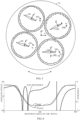
- An example of positioning the computational probes 500 at different foil positions is shown in Figure 5 .
- a distance DD between a probe 500 and a corresponding foil 108 adjacent to it may be such that the probe 500 is not be too close to the foil 108 such that the foil itself disturbs the flow adjacent to it too much and not too far such that the correlation between the velocity of the water movement at the probe 500 and at the foil adjacent to it remains high.
- a suitable distance DD may be about 3 ⁇ 4 chord length in front of the pivot point. More generally, the range of the distance DD may be from about 0.5 to about 1 chord length, for example.
- the wake field W should be representative over the foil's span (average in z-direction) but for simplicity it may be assumed that a single point at about the middle is good enough. In the case the wake field W is measured, the at least one sensor 122 may be placed in a corresponding location as the computational probe 500.
- the wake field W contributions may have quite complex shapes.
- contributions of the wake field W may be continually iterated within the CFD simulation.
- step 7 too large a change i.e. overshoot should be avoided because a new iterated pitch function also changes the measured V x + and V y + and large overshoot will slow down or even prevent the convergence of an iterative process.
- only two iterative rounds of the steps 1) to 8) may be enough, because beyond that the changes typically become marginal.
- a comparison of the contributions of a truncated wake field W to actual ones are presented in Figure 6 and its explanation.
- Equation (1) determines the pitch angle ⁇ ( ⁇ ) of a foil 108, 108'. Then, the pitch trajectory of a foil is fixed regardless of the speed and RPM (Rotation Per Minute), and the foil wheel 106, 106' acts similarly to a fixed pitch screw propeller (or a trochoidal foil wheel with constant eccentricity).
- the undisturbed contribution V xy , 0 + of the wake field is directly available since undisturbed speed and RPM are easily obtained.
- velocities of the induced dimensional contribution V xy, ind of the wake field W are locally (at any given ⁇ ) directly proportional to the wheel rotational speed ⁇ R. It may be reasonable to assume that the induced velocity is indeed proportional to the velocity inducing it.
- the pitch angle of a foil may reduce the side force.
- the side force may be adjusted to large value in order to steer the marine vehicle 100 to turn. From the steering perspective, it may however be desirable that the propulsion system 102 has zero or only a weak side force in a straight ahead condition. Both the instantaneous thrust and the side force depend on the corresponding angle of attack ⁇ ( ⁇ ). Well below the stall angle, a larger angle of attack ⁇ ( ⁇ ) increases both.
- Equation (1) an asymmetric constant angle of attack
- Equation (2) an asymmetric constant angle of attack
- An asymmetric smooth square wave can be obtained with approximately constant value +15° on the leading side and -13° on the trailing side (see Figure 3 ).
- the rotation rate may be increased.
- the inclusion of the local, variable wake field W allows to achieve even a very high efficiency, of order 85%.
- it is possible to achieve similar efficiency levels by expressing the pitch function ⁇ ( ⁇ ) as a series of periodic functions and optimizing the coefficients by using the local, variable wake field W as an input to the optimization.
- the underlying physics can be linked to the optimization more broadly which in turn allows to reach for a high efficiency more generally.
- pitch function parameters (X 1 , ..., X N ) which may be considered the data related to the pitch angle, an objective functions by E, and constraint functions by C.
- the parameters X, objective function E and constraint function C may be considered vectors when the controller 112 performs the algorithm.
- the optimization problem may be described as below: The object function is maximized or optimized using Max operator, Max E ( X ).
- the constraint function is subjected to limitations, C u ⁇ C ( X ) ⁇ C L , where C U and C L are the higher and lower bound(s) for C, respectively.
- the pitch function parameters may have limits: X L ⁇ X ⁇ X U , where X L and X U are the lower and higher bounds for X, respectively.
- the objective function E and constraint function C relate to the foil foil wheel performance variables like thrust, side force, and efficiency, for example.
- the optimization objective may maximize the efficiency ( E ) with constraint on thrust ( C ); or maximize thrust ( E ) with efficiency ( C ) larger than a set value.
- the periodic function f( X ) could be expressed using at least one spline function, for example.
- the spline functions are functions that may be defined by polynomials in a piecewise manner.
- the periodic function f( X ) could include at least one elementary function that is at least two times derivable, for example.
- the optimization problem can be performed as follows.
- the object function E is maximized or optimized using Max operator, Max E ( X, W ).
- the constraint function is subjected to limitations, C U ⁇ C ( X ) ⁇ C L , where C U and C L are the higher and lower bound(s) for C, respectively, C U ⁇ C ( X ) ⁇ C L , where C U and C L are the higher and lower bound(s) for C, respectively.
- Limits of the pitch function parameters depend on eventual operational conditions and application. For example, for a normal trochoidal-like operation the derived angle of attack should be restricted from a stall mode.
- the controller 112 may form the data on the pitch angle ⁇ ( ⁇ ) by optimizing an efficiency and/or a thrust of a model formed of a set of second-order continuous periodic functions of the pitch angle ⁇ ( ⁇ ), having an angle of attack ⁇ and the wake field W as its arguments with or without an operational demand and/or a constraint.
- the second order continuous periodic function refers to a function that have the first and second derivatives.
- the controller 112 may form the data on the pitch angle ⁇ ( ⁇ ) by maximizing an efficiency and/or a thrust of a model formed of a set of second-order continuous periodic functions of the pitch angle ⁇ ( ⁇ ).
- the controller 112 may receive or have available data on a location of the marine vehicle 100, other marine vehicles, wind conditions, and/or tide, for example, and the controller 112 may utilize the received data in the formation of the pitch angle ⁇ ( ⁇ ).
- the data on the location may include information on streams, which are caused by a river or rivers nearby at the location, and/or a map of the bottom at the location, and the controller 112 may estimate the wake field W based on at least one of them.
- the controller 112 may additionally or alternatively estimate the wake field W based on the wind and/or tidal conditions.
- FIG. 7 illustrates an example of a pitch angle trajectory of a foil with respect to a rotation angle of the foil wheel in an arbitrary but common scale.
- the x-axis represents the rotation angle ⁇ of the foil wheel and the y-axis represents the pitch angle ⁇ . It can be seen that the new approach explained in this document may result in a different trajectory from that of a cycloidal foil pitch trajectory that is conventional.
- FIG. 8 is a flow chart of the controlling method.
- step 800 forming data on a pitch angle ⁇ ( ⁇ ) of at least one foil 108, 108', which is individually controllable and in a rotatable manner attached with a foil wheel 106, 106', based on an angularly variable wake field W( ⁇ ) affecting the at least one foil 108, 108' and an angle ⁇ of a rotation of the foil wheel 106, 106' is formed by a controller 112.
- the at least one foil 108, 108' is set at the pitch angle ⁇ ( ⁇ ) based on the data by an actuator arrangement 110 receiving the data from the controller 112.
- the method shown in Figure 7 may be implemented as a logic circuit solution or computer program.
- the computer program may be placed on a computer program distribution means for the distribution thereof.
- the computer program distribution means is readable by a data processing device, and it encodes the computer program commands, carries out the measurements and optionally controls the processes on the basis of the measurements.
- the computer program may be distributed using a distribution medium which may be any medium readable by the controller.
- the medium may be a program storage medium, a memory, a software distribution package, or a compressed software package.
- the distribution may be performed using at least one of the following: a near field communication signal, a short distance signal, and a telecommunications signal.
- the improvements and benefits of the formation of the pitch angle of the foil trajectory as a function of the wake field W may be the following.
- the angle of attack that may be kept constant or in a constant range for a maximized length of the rotation of the foil wheel.
Landscapes
- Chemical & Material Sciences (AREA)
- Engineering & Computer Science (AREA)
- Combustion & Propulsion (AREA)
- Mechanical Engineering (AREA)
- Ocean & Marine Engineering (AREA)
- Physics & Mathematics (AREA)
- Fluid Mechanics (AREA)
- Control Of Position, Course, Altitude, Or Attitude Of Moving Bodies (AREA)
- Toys (AREA)
Description
- The invention relates to a method of controlling a propulsion system of a marine vehicle and a propulsion system.
- A marine vehicle may move with respect to water around it with thrust from a propulsion system, which includes one or more rotating foil wheels with individually controllable foils that extend vertically downwards. With individual foil pitch control, a typical a propulsion system works with a relatively high efficiency. The efficiency is based on an optimization of a pitch angle of the foils using either a trochoidal path, which depends on a function having a constant eccentricity and a rotation angle of the foil wheel as arguments, or a path described by a variable eccentricity and trigonometric functions having the rotation angle of the foil wheel as an argument. A propulsion systems comprising a foil wheel and at least one foil which is individually controllable and in a rotatable manner attached with the foil wheel, and method of controlling such a propulsion system is disclosed by the documents
US 2015/321740 A1 ,DE 201 17 451 U1 orCN 107 187 570 B . - However, as the prior art performs a mere parametric optimization but does not properly take into account the real world conditions, a result of optimized model coefficients is obtained for a single operating point only such as speed or thrust only. If another operating point is required, the model coefficients need to be optimized again for the best performance. This is a tedious process and eventually a numerical map for all model coefficients would be required to cover the entire operating range. All in all, such a process is impractical or even impossible, which may eventually lead to a low efficiency and thrust, wear of the propulsion system and high fuel consumption, which in turn may increase pollution and even health risks.
- Hence, an improvement would be welcome.
- The present invention seeks to provide an improvement in the control.
- The invention is defined by the independent claims. Embodiments are defined in the dependent claims.
- Example embodiments of the present invention are described below, by way of example only, with reference to the accompanying drawings, in which
-
Figure 1 illustrates an example of a marine vehicle; -
Figure 2 illustrates an example of a propulsion system; -
Figure 3 illustrates an example of a symmetric smooth square wave and an asymmetric smooth square wave; -
Figure 4 illustrates an example of a foil rotating at an angular speed at an arbitrary foil location; -
Figure 5 illustrates an example of positioning the computational probes or sensors adjacent to at least one foil; -
Figure 6 illustrates an example of instantaneous foil efficiency, a target angle of attack and an actual angle of attack; -
Figure 7 illustrates an example of a pitch angle trajectory of a foil with respect to a rotation angle of the foil wheel; and -
Figure 8 illustrates of an example of a flow chart of a controlling method. - The following embodiments are only examples. Although the specification may refer to "an" embodiment in several locations, this does not necessarily mean that each such reference is to the same embodiment(s), or that the feature only applies to a single embodiment. Single features of different embodiments may also be combined to provide other embodiments. Furthermore, words "comprising" and "including" should be understood as not limiting the described embodiments to consist of only those features that have been mentioned and such embodiments may also contain features/structures that have not been specifically mentioned. All combinations of the embodiments are considered possible if their combination does not lead to structural or logical contradiction.
- It should be noted that while Figures illustrate various embodiments, they are simplified diagrams that only show some structures and/or functional entities. The connections shown in the Figures may refer to logical or physical connections. It is apparent to a person skilled in the art that the described apparatus and/or system may also comprise other functions and structures than those described in Figures and text. It should be appreciated that details of some functions, structures, and the signalling used for measurement and/or controlling are irrelevant to the actual invention. Therefore, they need not be discussed in more detail here.
-
Figure 1 illustrates an example of a marine vehicle 100 (the marine vehicle is only partly shown inFigure 1 ) with apropulsion system 102, which comprises twopropulsion sub-systems 104, 104'. In general, thepropulsion system 102 may comprise one ormore propulsion sub-systems 104, 104'. Marine vehicles may include transport vessels and passenger ships. The transport ships may include cargo vessels and containers, for example. Additionally, the marine vehicles may refer to fishing vessels, service craft like tugboats and supply vessels, and warships. Furthermore, the marine vehicles may be used as ferries and submarines. - Each of the
propulsion sub-system 104, 104' comprises afoil wheel 106, 106', Each of thefoil wheels 106, 106', in turn, comprises at least onefoil 108, 108'. Afoil 108, 108' is a blade that extends downwards from thefoil wheel 106, 106'. At least one of thefoils 108, 108' is individually controllable and in a rotatable manner attached with thefoil wheel 106, 106'. Typically all thefoils 108, 108' are individually controllable in a rotatable manner with respect to the foil wheel(s) 106, 106'. - As illustrated in the example of
Figure 1 , awheel engine system 120 may be common to a plurality of thepropulsion sub-systems 104, 104' through a mechanical power transmission. -
Figure 2 illustrates an example where thepropulsion system 102 comprises onefoil wheel 106. That is, thepropulsion system 102 may be correspond to one of thepropulsion sub-systems 104, 104'. Additionally, thepropulsion system 102 comprises anactuator arrangement 110 and acontroller 112. Thecontroller 112 may be common to allpropulsion sub-systems 104, 104' (seeFigure 1 ) or thecontroller 112 may comprise a sub-controller for each of a plurality ofpropulsion sub-systems 104, 104' (such a possibility is illustrated inFigure 2 although thecontroller 112 inFigure 2 may also be for a plurality of foil wheels). - The
controller 112 comprises one ormore processors 114 and one ormore memories 116 including computer program code. The one ormore memories 116 and the computer program code causes thecontroller 112, with the one ormore processors 114, to form data on a pitch angle γ(θ, t) of at least onefoil 108 based on an angle θ of a rotation of thefoil wheel 106, to which the at least onefoil 108 is mechanically connected, and an angularly variable wake field W, which naturally depends also on time and affects the at least onefoil 108, the angular dependence coming from the angle θ of the rotation of thefoil wheel 106. This may be mathematically expressed as: γ(θ(t)) = J(θ(t), W(θ(t)) or shorter γ(θ) = J(θ, W(θ)), where J is a function or an operation that models the pitch angle γ(θ) of the foil(s) 108, 108', t is time, and the angle θ of a rotation of thefoil wheel 106 and W(θ(t)), which is the temporally variable wake field W, are its arguments. - The pitch angle of a foil γ(θ) may also be called a foil pitch trajectory because it is a function of a rotation angle θ of the foil wheel and it forms a curve (see
Figure 3 ). The wake field W may be determined as a velocity field of water relative of themarine vehicle 100. The wake field W can be considered to refer to a field of laminar or turbulent currents of water. The wake field W may be caused by the at least onefoil 108 of the same ordifferent foil wheel 106, the one ormore foils 108, 108', and/or a hull of themarine vehicle 100. Additionally, the wake field W may be caused by streams in the water, the streams having a source different from themarine vehicle 100 itself. The streams in the water may be generated by a river, a tide, other marine vehicle(s) and/or wind(s). The streams in the water may also vary and cause a variable wake field W due to a bottom shape under the water although that is not the source of the streams. In the prior art, the models for controlling the pitch angle γ(θ) have had no direct link to the underlying physics. By incorporating the wake field W in the model, it is possible to find a more realistic control of any foil of thepropulsion system 102. - The
controller 112 then communicates the data on the pitch angle γ(θ) to theactuator arrangement 110, which sets the at least onefoil 108 at the pitch angle γ(θ) based on the data formed by thecontroller 112. The data may include parameters for the pitch angle and/or at least one value for the pitch angle. Theactuator arrangement 110 may comprise an electric motor arrangement AR for each of the at least onefoil 108. The electric motor arrangement AR may comprise a regulator and an electric motor, which turns the foil it is mechanically coupled with according to the pitch angle γ(θ) from the regulator, which received the data on the pitch angle γ(θ) from thecontroller 112. What is explained for thefoil wheel 106 and foils 108 ofFigure 2 may correspondingly be applied also to the foil wheel 106' and foils 108' inFigure 1 . - Instead of a tedious process of several CFD (Computational Fluid Dynamics) simulations per operating point and a numerical map for all model coefficients, the optimal pitch angle can simultaneously produce a high efficiency and a small (compared to thrust) side force in straight ahead operation. That is, both issues can be addressed together. This new routine produces an optimal pitch angle of a foil in the ship's wake, unlike the prior art mere parametric optimizations restricted to open water conditions only.
- The
controller 112 may also control adrive 118 of awheel engine system 120. Thewheel engine system 120 may comprise an engine, which may comprise an electric engine, a combustion engine such as a diesel engine, petrol engine or a gas engine, and potentially a mechanical gearbox. Thecontroller 112 may send a command to thedrive 118 which may then control a rotation speed and/or a direction of rotation of thewheel motor 120. Thewheel engine system 120 rotates thefoil wheel 106 directly or through the gearbox. However, these kinds of details of thewheel engine system 120 are less relevant to the actual invention and a person skilled in the art is familiar with variouswheel engine systems 120, per se. Therefore, they are not discussed in more detail here. As illustrated in an example ofFigure 2 , each of thepropulsion sub-systems 104, 104' may have its ownwheel engine system 120. - In an embodiment, the
controller 112 may be connected with at least onesensor 122, which measures the wake field W in the water when themarine vehicle 100 is operating on the sea, river or lake, for example. Then the at least onesensor 122 may communicate the data on the wake field W to thecontroller 112 in a wired or wireless manner. The at least onesensor 122 is suitably located with respect to the at least onefoil 108 in order to measure the wake field W affecting each of the at least onefoil 108 as a function of time and location (see alsoFigure 5 and its description). Thecontroller 112 may form an estimate of the wake field W at and/or adjacent to the at least one foil based on values measured by the at least onesensor 122. - In an embodiment, the wake field W may be based on a simulation of water movements, around and affecting the at least one
foil 108, caused by thepropulsion system 102 in the water (see alsoFigure 5 and its description). Hence, the wake field W may be based on a simulation of water movements, around and affecting the at least onefoil 108, caused by one ormore foils 108, 108'. - As already explained the
propulsion system 102 of amarine vehicle 100 can be controlled by thecontroller 112, which forms the data on the pitch angle γ(θ) of the at least onefoil 108, 108' based on the angle θ of a rotation of thefoil wheel 106 and the temporally variable wake field W affecting the at least onefoil 108, 108'. A strength of the wake field W affecting the at least onefoil 108, 108' is location dependent in addition to the temporal dependency, and that is why thecontroller 112 provides new data on the pitch angle γ(θ) repeatedly or continuously for adjusting the pitch angle of the at least onefoil 108, 108'. The angle θ of a rotation of thefoil wheel 106 is also temporally varying when thefoil wheel 106 is rotating. - In an embodiment, the
controller 112 may form the data on the pitch angle γ(θ) of the at least onefoil 108, 108' under influence of the wake field W, which is at least partly caused by propulsion of thepropulsion system 102. The wake field W may have been caused by thefoils 108, 108' and/or thefoil wheel 106, 106'. - In an embodiment, the
controller 112 may form the data on the pitch angle γ(θ) of a foil under influence of the wake field W, which is at least partly caused by at least one other foil. The at least one other foil and thefoil 108, for which the data on the pitch angle γ(θ) is formed, are attached to thesame foil wheel 106 in this example. Here the at least one other foil is a foil, which is different from the one for which the data on the pitch angle γ(θ) is formed. - In an embodiment, the
controller 112 may form the data on the pitch angle γ(θ) of the at least onefoil 108 under influence of the wake field W, which is at least partly caused by a hull of themarine vehicle 100. The movement of themarine vehicle 100 namely causes also movement of water such as currents or streams around and adjacent to themarine vehicle 100. - In an embodiment, the
controller 112 may form the data on the pitch angle γ(θ) of the at least one foil under influence of the wake field W, which is at least partly caused by environment of themarine vehicle 100. The environment may include at least one of the following: a river, a tide, at least one other marine vehicle, wind and/or a bottom shape under the water. Although the wind does not directly cause a part of the wake field W, the wind causes water to move as currents or streams which may be taken into account in the wake field W. - In an embodiment, the
controller 112 may form the data on the pitch angle γ(θ) for each of a plurality offoils 108 individually controllable and attached in a rotatable manner to thefoil wheel 106. That is, all thefoils 108, 108' of thepropulsion system 102 may be controlled. - In an embodiment, the
controller 112 may form the data on the pitch angle γ(θ) of at least onefoil 108 under influence of the wake field W caused at least partly by a plurality ofpropulsion sub-systems 104, 104' of thepropulsion system 102, thepropulsion sub-systems 104, 104' comprisingfoils 108, 108' attached therewith including the at least one foil. - In an embodiment, the
controller 112 may form the data on the pitch angle γ(θ) of at least onefoil 108 while keeping an absolute angle of attack α of the at least onefoil 108 constant within a tolerance for a maximized length of rotation of thefoil wheel 106. The term absolute, which may also be called modulus, refers to a non-negative value of the angle of attack α regardless of its sign. Mathematically, the absolute value of the angle of attack α may be written as |α|. The tolerance, in turn, may be predetermined. The tolerance may alternatively or additionally depend on a resolution of the data processing, mechanical settings and/or allowable mechanical limit(s) or variation of the limit(s). The tolerance may be any combination of these or the like, for example. In an embodiment, thecontroller 112 may form the data on the pitch angle γ(θ) of at least onefoil 108 while keeping the angle of attack a of the at least onefoil 108 at alternative constants for a maximized length of rotation of thefoil wheel 106, the constants having opposite signs. This angle of attack may apply to the symmetric square wave target, for example. The angle of attack a may be an estimation formed by the model, or the angle of attack a may be a measured value. - In the prior art, basic pitch angle of a foil has been described by a trochoidal path

Figure 3 ), θ is the foil wheel rotation angle measured counter clockwise from the x-axis, and r+ is the eccentricity (a constant in this kind of prior art example), used to control the pitch angle of a foil. Thefoil wheel 106, 106' is assumed to rotate in the positive θ direction with angular speed ω. With trochoidal foil pitch trajectories have attained computational (with CFD) efficiencies around η = 0.8. In another prior art example, the pitch angle of a foil has a varying eccentricity r+ as a function of the foil wheel rotation angle θ, and finding theoptimal coefficients 


- It may be considered that a foil profile in transversal motion with respect to the incident flow has a single angle of attack α that produces a peak efficiency. Thus in such an embodiment, the data on the pitch angle γ(θ) of at least one
foil 108, 108' may be formed while keeping the angle of attack α of the at least onefoil 108, 108' close to this optimal constant value for a maximized length of rotation, in a manner allowing the sign of the angle alternate, as shown inFigure 3 for the smooth square wave target function for the angle α of attack.. In an embodiment, the angle of attack α of the at least onefoil 108, 108' is kept at the optimal constant value for a maximized length of rotation. In an embodiment, the angle of attack α of the at least onefoil 108, 108' is kept within a predetermined range from the optimal constant value for a maximized length of rotation. The maximization of the length may be included in the model function or the maximization may be caused by a maximizing operator performing the maximization of the model function. The maximization of the length of rotation of thefoil wheel 106, 106' with a constant angle of attach is prior art, per se. - In an embodiment, the optimum angle of attack α may lead to a peak efficiency up to η = 0.9 and gradual decrease with smaller and higher angles. On the other hand, the angle of attack α cannot obviously be constant over the whole foil rotation (360°) of the
foil wheel 106, 106' but, in order to produce positive thrust, the angle of attack α is positive while thefoil 108, 108' is moving in positive y-direction (the leading side) and negative while thefoil 108, 108' is moving in negative y-direction (the trailing side). A smooth square wave ssw is proposed for the base shape of the target angle of attack αtarget:

Figure 3 using the dashed curve. The use of this asymmetric smooth square wave for side force adjustment may be elaborated in an embodiment (seeFigure 6 and the description related to it). The continuous line inFigure 3 refers to an example of a symmetric ssw, A = 15°, B = 0°. -
Figure 4 illustrates an example of thefoil 108 rotating at an angular speed ω at an arbitrary foil location expressed as function of the rotation angle θ of thefoil wheel 106. The data on the pitch angle γ(θ) of afoil 108, 108' may be formed such that a target angle of attack α (with chosen amplitude) is attained as closely as possible. Mathematically, the situation can be characterized in a following manner, for example:


foil 108, 108' may be written as



- Although the measurement with at least on
sensor 122 may be possible, the fact that not only is the wake field W required as a function θ but also exactly at the same instant an angle θ of thefoil wheel 106, 106' is required, may make it challenging. In an embodiment, the wake field W contributions may be recorded from a CFD simulation. This may be accomplished by placing acomputational probe 500 adjacent to afoil 108, 108' such that it follows the rotation of thefoil wheel 106, 106'. In an embodiment, the computational probe does not the foil pitching and may remain static relative to a pivot point of the foil it follows. In this embodiment, the vector pointing from the pivot point to the probe is always parallel to the x-axis. An example of positioning thecomputational probes 500 at different foil positions is shown inFigure 5 . - A distance DD between a
probe 500 and acorresponding foil 108 adjacent to it may be such that theprobe 500 is not be too close to thefoil 108 such that the foil itself disturbs the flow adjacent to it too much and not too far such that the correlation between the velocity of the water movement at theprobe 500 and at the foil adjacent to it remains high. In an embodiment, a suitable distance DD may be about ¾ chord length in front of the pivot point. More generally, the range of the distance DD may be from about 0.5 to about 1 chord length, for example. In principle, the wake field W should be representative over the foil's span (average in z-direction) but for simplicity it may be assumed that a single point at about the middle is good enough. In the case the wake field W is measured, the at least onesensor 122 may be placed in a corresponding location as thecomputational probe 500. - The wake field W contributions may have quite complex shapes.
- In an embodiment, contributions of the wake field W may be continually iterated within the CFD simulation. The control system, particularly a PID (Proportional Integral Derivative) control system requires a continuous analytical function with at least one continuous derivative. If the wake field W is collected at Δθ = 1° intervals, i.e. at every degree of a 360° rotation of the
foil wheel 106, 106', from a CFD simulation or from measurements performed by the at least onesensor 122, a discrete Fourier transform may be utilized to form a good model based on continuous trigonometric functions with a total of 360 (full rotation) terms for each wake contribution. - However, feeding such an amount of data on the wake field W to a real machine's control system may be impractical. Furthermore, the real wake field W may not be similar to the simulation in all details. Hence in an embodiment, only a constant average term and/or a few lowest frequency sine and cosine terms from a Fourier series representation of the wake field contributions may be retained. For example three lowest frequency sine and cosine terms may be enough. These truncated functions may then be processed according to Equation (2A) or (2B) in the
controller 112, for example. Based on this kind of an algorithm, thecontroller 112 may form the data on the pitch angle of a foil in a new CFD simulation. Since the wake field W also depends on the pitch angle of a foil, this may be done iteratively in an embodiment. The iterative process may be performed as follows: - 1) Initialize the pitch angle of a foil in Equation (2B) with


- 2) Obtain converged CFD solution and record actual


- 3) Form Fourier series representations by retaining the constant and only a few sine and cosine terms
- 4) Feed a truncated Fourier series representations


- 5) Obtain a new converged CFD solution and record new actual


- 6) Form a new truncated Fourier series representations


- 7) Under-relax to avoid overshoot by averaging with the previous round

and
- 8) Return to step 4).
- In step 7), too large a change i.e. overshoot should be avoided because a new iterated pitch function also changes the measured


Figure 6 and its explanation. - In an embodiment, while the angle of attack α(θ) is kept constant for a maximized length round the rotation of the
foil wheel 106, 106', and the data on the pitch angle γ(θ) is iterated to a single design point (velocity and RPM), the contributions

foil 108, 108'. Then, the pitch trajectory of a foil is fixed regardless of the speed and RPM (Rotation Per Minute), and thefoil wheel 106, 106' acts similarly to a fixed pitch screw propeller (or a trochoidal foil wheel with constant eccentricity). If it is assumed that the RPM is constant, at slow speeds the actual angle of attack α(θ) is large, and a high thrust with reduced efficiency is obtained. As the speed increases towards the designed speed, the actual angle of attack α(θ) approaches the target behaviour, and a high efficiency is recovered. - However, this behaviour may also be improved in an embodiment. Decompose now a scaled wake field


foil wheel 106, 106', which is with themarine vehicle 100 in self-propulsion situation, real or simulated, and an extra contribution
foils 108, 108'. - The undisturbed contribution


- This means that the scaled induced contributions

foil wheel 106. Hence, by determining the scaled wake field V^, at the design speed and RPM, it is possible to use Equations (3) and (4) to reconstruct a reasonable estimate of the wake field W at any other operating point. Equation (4) is approximate but overall the reconstructed wake field W will give a close match to the target angle of attack α(θ) at an arbitrary operating point. With the reconstructed wake field W, a high efficiency can be obtained over a wide range of operating points. - While the angle of attack α(θ) is constant along a maximized length of the rotation of the
foil wheel 106, 106', the pitch angle of a foil may reduce the side force. In an embodiment, it is possible to modify the target angle of attack α(θ) in order to adjust the side force to zero or a large value. In an embodiment, the side force may be adjusted to large value in order to steer themarine vehicle 100 to turn. From the steering perspective, it may however be desirable that thepropulsion system 102 has zero or only a weak side force in a straight ahead condition. Both the instantaneous thrust and the side force depend on the corresponding angle of attack α(θ). Well below the stall angle, a larger angle of attack α(θ) increases both. - For example, with a constant ±15° angle of attack, the net side force is positive and by increasing the leading side (around θ = 0/360°) angle of attack or decreasing the trailing side (around θ = 180°) angle of attack, the positive net side force will decrease. For this, an asymmetric constant angle of attack, Equation (1), may be inserted to Equation (2A) or (2B) in place of the symmetric constant angle of attack, and setting A = 14° and B = 1°, for example. An asymmetric smooth square wave can be obtained with approximately constant value +15° on the leading side and -13° on the trailing side (see
Figure 3 ). To compensate for the loss of thrust due to a smaller angle of attack on the trailing side, the rotation rate may be increased. With these settings, the iterative process to obtain an approximate wake field W is repeated. An example of the resulting actual angle of attack α(θ) with the target angle of attack α(θ)target and the instantaneous foil efficiency are presented inFigure 6 . Again, the actual angle of attack α(θ) follows the target angle of attack α(θ)target quite well, and high efficiency levels are maintained. The performance results behave as expected. The efficiency is further increased and the side force is reduced compared with the prior art in this optimization example, but the thrust is slightly reduced. The reduced thrust may be compensated with a further increase in rotation rate or by adjusting the asymmetry a bit down, say to A = 14.1 and B = 0.9°. The central performance figures of this +15°/-13° asymmetric constant angle of attack case are listed in Table 1. For reference, the corresponding performance figures of the symmetric +15°/-15° constant angle of attack case are listed in Table 2.TABLE 1. Performance of an example of the asymmetric constant angle of attack (+15°/-13°) P (MW) Fx (kN) Fy (kN) η D (m) RPM α (°) 1.838 164.2 -7.0 0.850 3.0 38.14 +15/-13 Table 2. Performance of the constant angle of attack (±15°) foil pitch trajectory case P [MW] Fx [kN] Fy [kN] η D [m] RPM α 1.933 172.3 28.5 0.849 3.0 37.14 ±15° - By optimizing the pitch angle γ(θ) with the wake field W leads to both a high efficiency and a small side force when propagating straight ahead.
- The inclusion of the local, variable wake field W allows to achieve even a very high efficiency, of order 85%. In addition to a constant angle of attack formulation, it is possible to achieve similar efficiency levels by expressing the pitch function γ(θ) as a series of periodic functions and optimizing the coefficients by using the local, variable wake field W as an input to the optimization. In this manner, the underlying physics can be linked to the optimization more broadly which in turn allows to reach for a high efficiency more generally.
- As an example of the optimization of the pitch angle γ(θ), it may be expressed in a mathematical form in a following manner. Denote pitch function parameters by X = (X1, ..., XN) which may be considered the data related to the pitch angle, an objective functions by E, and constraint functions by C. The parameters X, objective function E and constraint function C may be considered vectors when the
controller 112 performs the algorithm. The optimization problem may be described as below:
The object function is maximized or optimized using Max operator, Max E(X). The constraint function is subjected to limitations, Cu ≥ C (X) ≥ C L, where C U and C L are the higher and lower bound(s) for C, respectively. - The pitch function parameters may have limits: X L ≤ X ≤ X U, where X L and X U are the lower and higher bounds for X, respectively.
- Here the objective function E and constraint function C relate to the foil foil wheel performance variables like thrust, side force, and efficiency, for example. The optimization objective may maximize the efficiency (E) with constraint on thrust (C); or maximize thrust (E) with efficiency (C) larger than a set value.
- The pitch angle γ(θ) can be calculated from the pitch function parameters X: γ(θ) = f(X), where f(X) is a periodic function of the angular position θ with k continuous derivatives, where k ≥ 2 to have a smooth curve and avoid rapid changes of the blade orientation considering moment limits of the blade motor. The periodic function f(X) could be expressed using at least one spline function, for example. The spline functions are functions that may be defined by polynomials in a piecewise manner. The periodic function f(X) could include at least one elementary function that is at least two times derivable, for example.
- When a wake field W is included in the optimization, the optimization problem can be performed as follows. The object function E is maximized or optimized using Max operator, Max E(X, W). The constraint function is subjected to limitations, C U ≥ C (X) ≥ C L, where C U and C L are the higher and lower bound(s) for C, respectively, C U ≥ C (X) ≥ C L, where C U and C L are the higher and lower bound(s) for C, respectively. Limits of the pitch function parameters depend on eventual operational conditions and application. For example, for a normal trochoidal-like operation the derived angle of attack should be restricted from a stall mode.
- In an embodiment, the
controller 112 may form the data on the pitch angle γ(θ) by optimizing an efficiency and/or a thrust of a model formed of a set of second-order continuous periodic functions of the pitch angle γ(θ), having an angle of attack α and the wake field W as its arguments with or without an operational demand and/or a constraint. The second order continuous periodic function refers to a function that have the first and second derivatives. - In an embodiment, the
controller 112 may form the data on the pitch angle γ(θ) by maximizing an efficiency and/or a thrust of a model formed of a set of second-order continuous periodic functions of the pitch angle γ(θ). - In an embodiment, the
controller 112 may receive or have available data on a location of themarine vehicle 100, other marine vehicles, wind conditions, and/or tide, for example, and thecontroller 112 may utilize the received data in the formation of the pitch angle γ(θ). The data on the location may include information on streams, which are caused by a river or rivers nearby at the location, and/or a map of the bottom at the location, and thecontroller 112 may estimate the wake field W based on at least one of them. Thecontroller 112 may additionally or alternatively estimate the wake field W based on the wind and/or tidal conditions. - While forming the pitch angle γ(θ) in the above explained manner, the pitch angle γ(θ) becomes unconventional and an optimum hydrodynamical performance may be achieved.
Figure 7 illustrates an example of a pitch angle trajectory of a foil with respect to a rotation angle of the foil wheel in an arbitrary but common scale. The x-axis represents the rotation angle θ of the foil wheel and the y-axis represents the pitch angle γ. It can be seen that the new approach explained in this document may result in a different trajectory from that of a cycloidal foil pitch trajectory that is conventional. -
Figure 8 is a flow chart of the controlling method. Instep 800, forming data on a pitch angle γ(θ) of at least onefoil 108, 108', which is individually controllable and in a rotatable manner attached with afoil wheel 106, 106', based on an angularly variable wake field W(θ) affecting the at least onefoil 108, 108' and an angle θ of a rotation of thefoil wheel 106, 106' is formed by acontroller 112. Instep 802, the at least onefoil 108, 108' is set at the pitch angle γ(θ) based on the data by anactuator arrangement 110 receiving the data from thecontroller 112. - The method shown in
Figure 7 may be implemented as a logic circuit solution or computer program. The computer program may be placed on a computer program distribution means for the distribution thereof. The computer program distribution means is readable by a data processing device, and it encodes the computer program commands, carries out the measurements and optionally controls the processes on the basis of the measurements. - The computer program may be distributed using a distribution medium which may be any medium readable by the controller. The medium may be a program storage medium, a memory, a software distribution package, or a compressed software package. In some cases, the distribution may be performed using at least one of the following: a near field communication signal, a short distance signal, and a telecommunications signal.
- The improvements and benefits of the formation of the pitch angle of the foil trajectory as a function of the wake field W may be the following. During the formation of the pitch angle, the angle of attack that may be kept constant or in a constant range for a maximized length of the rotation of the foil wheel.
- 1) High gains in efficiency up to η = 0.85;
- 2) Direct link to physics (the wake field) allows utilization of design point parameters over the whole operating range unlike parametrically optimized pitch trajectories;
- 3) The optimal performance of parametrically optimized trajectories is restricted to open water conditions, whereas the constant angle of attach trajectory becomes optimal with the marine vehicle when the utilized wake field is recorded from a CFD simulation or measurement;
- 4) Ability to adjust side force to zero without loss of efficiency (with the asymmetric angle of attack αtarget) in straight ahead operation;
- 5) Avoid flow separation/stall induced losses in thrust and efficiency (angle of attack is controlled);
- 6) A "high thrust" mode is obtained simply by increasing the amplitude of the angle of attack αtarget (not over the stall angle).
- It will be obvious to a person skilled in the art that, as technology advances, the inventive concept can be implemented in various ways. The invention and its embodiments are not limited to the example embodiments described above but may vary within the scope of the claims.
Claims (15)
- A method of controlling a propulsion system (102) of a marine vehicle (100), characterized by forming (800), by a controller (112), data on a pitch angle (γ(θ)) of at least one foil (108, 108'), which is individually controllable and in a rotatable manner attached with a foil wheel (106, 106'), based on an angularly variable wake field (W(θ)) affecting the at least one foil (108, 108') and an angle (θ) of a rotation of the foil wheel (106, 106'); and
setting (802), by an actuator arrangement (110) receiving the data from the controller (112), the at least one foil (108, 108') at the pitch angle (γ(θ)) based on the data. - The method of claim 1, characterized by forming the data on the pitch angle (γ(θ)) of the at least one foil (108, 108') under influence of the wake field (W), which is caused by propulsion of the propulsion system (102).
- The method of claim 2, characterized by forming the data on the pitch angle (γ(θ)) of a foil of the at least one foil (108) under influence of the wake field (W), which is caused by at least one other foil (108), which is different from the foil for which the data on the pitch angle is formed, the at least one foil (108) being attached to the foil wheel (106) to which the foil for which the data on the pitch angle is formed is also attached.
- The method of claim 1, characterized by forming the data on the pitch angle (γ(θ)) of the at least one foil (108) under influence of the wake field (W), which is caused by a hull of the marine vehicle (100).
- The method of claim 1, characterized by forming the data on the pitch angle (γ(θ)) of the at least one foil (108) under influence of the wake field (W), which is caused by environment of the marine vehicle (100).
- The method of claim 1, characterized by forming the data on the pitch angle (γ(θ)) for each of a plurality of foils (108) individually controllable and attached in a rotatable manner with the foil wheel (106).
- The method of claim 1, characterized by forming the data on the pitch angle (γ(θ)) of the at least one foil (108, 108') under influence of the wake field (W) caused by a plurality of propulsion sub-systems (104, 104') of the propulsion system (102), the propulsion sub-systems (104, 104') comprising foils (108, 108') attached therewith including the at least one foil (108, 108').
- The method of claim 1, characterized in that the wake field (W) is based on a simulation of the propulsion system (102) in the water.
- The method of claim 1, characterized by measuring the wake field (W) with at least one sensor (122) when the marine vehicle (100) is in the water, and communicating data on the wake field (W) to the controller (112).
- The method of claim 1, characterized by forming the data on the pitch angle (γ(θ)) of the at least one foil (108, 108') while keeping an absolute angle of attack (α) of the at least one foil (108, 108') constant within a tolerance for a maximized length of rotation of the foil wheel (106, 106').
- The method of claim 1 or 10, characterized by forming the data on the pitch angle (γ(θ)) of the at least one foil (108, 108') while keeping an angle of attack (α) of the at least one foil (108, 108') at two alternative constants within a tolerance for a maximized length of rotation of the foil wheel (106, 106'), the constants having opposite signs.
- The method of claim 1, characterized by decomposing a scaled wake field into a sum of an undisturbed contribution () and an extra contribution induced by the foils (108, 108');setting the induced scaled contribution caused by the every foil (108, 108') constant; anddetermining an approximate of the wake field (W) based on the induced scaled contribution that is locally constant.
- The method of claim 1, characterized by forming the data on the pitch angle (γ(θ)) by optimizing an efficiency and/or a thrust of a model formed of a set of second-order continuous periodic functions of the pitch angle (γ(θ)), angle of attack (α) and the wake field (W) with or without an operational demand and/or a constraint.
- A propulsion system (102) of a marine vehicle (100), wherein the propulsion system (102) comprises a foil wheel (106, 106'), at least one foil (108, 108'), which is individually controllable and in a rotatable manner attached with the foil wheel (106, 106'), an actuator arrangement (110) and a controller (112);
the controller (112) comprising one or more processors (114) and one or more memories (116) including computer program code; characterized in that the one or more memories (116) and the computer program code are configured to, with the one or more processors (114), cause at least the controller (112) to form data on a pitch angle (γ(θ)) of at least one foil (108, 108') based on an angle (θ) of a rotation of the foil wheel (106, 106') and an angularly variable wake field (W(θ)) affecting the at least one foil (108, 108'), and communicate the data on the pitch angle (γ(θ)) to the actuator arrangement (110), which is configured to set the at least one foil (108, 108') at the pitch angle (γ(θ)) based on the data. - A marine vehicle (100), characterized in that the marine (100) vehicle comprises the propulsion system of claim 14.
Applications Claiming Priority (1)
| Application Number | Priority Date | Filing Date | Title |
|---|---|---|---|
| PCT/EP2020/066192 WO2021249644A1 (en) | 2020-06-11 | 2020-06-11 | Method of controlling propulsion system of marine vehicle and propulsion system |
Publications (3)
| Publication Number | Publication Date |
|---|---|
| EP4164942A1 EP4164942A1 (en) | 2023-04-19 |
| EP4164942B1 true EP4164942B1 (en) | 2024-08-07 |
| EP4164942C0 EP4164942C0 (en) | 2024-08-07 |
Family
ID=71096693
Family Applications (1)
| Application Number | Title | Priority Date | Filing Date |
|---|---|---|---|
| EP20733237.0A Active EP4164942B1 (en) | 2020-06-11 | 2020-06-11 | Method of controlling propulsion system of marine vehicle and propulsion system |
Country Status (8)
| Country | Link |
|---|---|
| US (1) | US12583569B2 (en) |
| EP (1) | EP4164942B1 (en) |
| JP (1) | JP7850083B2 (en) |
| KR (1) | KR102854062B1 (en) |
| CN (2) | CN121106653A (en) |
| AU (1) | AU2020452061B2 (en) |
| ES (1) | ES2992164T3 (en) |
| WO (1) | WO2021249644A1 (en) |
Families Citing this family (2)
| Publication number | Priority date | Publication date | Assignee | Title |
|---|---|---|---|---|
| EP4442558A1 (en) * | 2023-04-03 | 2024-10-09 | Abb Schweiz Ag | Method of controlling propulsion of marine vehicle |
| EP4484273A1 (en) * | 2023-06-30 | 2025-01-01 | Abb Schweiz Ag | Controlling a marine vehicle propulsion system |
Citations (1)
| Publication number | Priority date | Publication date | Assignee | Title |
|---|---|---|---|---|
| CN107187570B (en) * | 2017-05-03 | 2019-04-30 | 武汉理工大学 | A Ship Whale Tail Propeller With High Propulsion Efficiency |
Family Cites Families (25)
| Publication number | Priority date | Publication date | Assignee | Title |
|---|---|---|---|---|
| DE19637786C1 (en) * | 1996-09-17 | 1998-02-26 | Voith Hydro Gmbh Schiffstechni | Cycloidal propeller |
| US5462406A (en) * | 1993-08-19 | 1995-10-31 | Vitron Systems Inc. | Cyclodial propulsion system |
| DE10060067A1 (en) * | 2000-12-01 | 2002-06-13 | Doczyck Wolfgang | Propulsion sail rotor for marine vessel has vertical axis rotor with adjustable vanes |
| US6948910B2 (en) * | 2002-07-12 | 2005-09-27 | Polacsek Ronald R | Spiral-based axial flow devices |
| US6743064B2 (en) * | 2002-09-11 | 2004-06-01 | The United States Of America As Represented By The Secretary Of The Navy | High-speed paddle wheel catamaran |
| US7762776B2 (en) * | 2006-03-14 | 2010-07-27 | Siegel Aerodynamics, Inc. | Vortex shedding cyclical propeller |
| US7686583B2 (en) * | 2006-07-10 | 2010-03-30 | Siegel Aerodynamics, Inc. | Cyclical wave energy converter |
| US8626366B2 (en) * | 2008-12-29 | 2014-01-07 | General Electric Company | System and method for controlling a marine vessel through a waterway |
| CN201525494U (en) * | 2009-11-10 | 2010-07-14 | 谢怀杰 | Perpendicular shaft self-adjusting blade angle resistance type ship propeller |
| US9562434B2 (en) * | 2010-11-03 | 2017-02-07 | National Research Council Of Canada | Oscillating foil turbine |
| US20120183399A1 (en) * | 2011-01-19 | 2012-07-19 | Hamilton Sundstrand Corporation | Method and apparatus for balancing wind turbines |
| US8231344B2 (en) * | 2011-07-05 | 2012-07-31 | General Electric Company | Methods for controlling the amplitude modulation of noise generated by wind turbines |
| CN102351038A (en) * | 2011-07-26 | 2012-02-15 | 杭州现代船舶设计研究有限公司 | Dynamic ship stabilizer |
| FR2993019B1 (en) * | 2012-07-05 | 2018-07-13 | Adv Tech Sas | MECHANISM FOR MONITORING THE INCIDENCE OF BLADES OF A ROTOR OPERATING IN A TRANSVERSE FLOW OF A FLUID |
| US9926058B2 (en) * | 2012-12-10 | 2018-03-27 | Sharrow Engineering Llc | Propeller |
| DE102015201636A1 (en) * | 2014-01-31 | 2015-08-06 | Voith Patent Gmbh | Watercraft, in particular tugs |
| EP2944556B1 (en) * | 2014-05-12 | 2018-07-11 | GE Energy Power Conversion Technology Ltd | Cycloidal marine-propulsion system |
| EP2977311A1 (en) * | 2014-07-24 | 2016-01-27 | ABB Oy | Dual mode oscillating foil propulsion system and method for oscillating at least one movable foil |
| FR3046131B1 (en) * | 2015-12-23 | 2018-01-26 | Thales | METHOD FOR CONTROLLING A PROPELLER OF A MARINE VEHICLE |
| FI128463B (en) * | 2016-10-17 | 2020-05-29 | Teknologian Tutkimuskeskus Vtt Oy | Marine propulsion system |
| DE102018202888A1 (en) * | 2018-02-26 | 2019-08-29 | MTU Aero Engines AG | Guide blade for the hot gas duct of a turbomachine |
| FR3090571B1 (en) * | 2018-12-19 | 2021-01-08 | Ecole Nat Superieure Darts Et Metiers Ensam | CYCLOIDAL DYNAMIC PROPULSION OR POSITIONING SYSTEM FOR A VESSEL |
| US11518482B1 (en) * | 2019-04-05 | 2022-12-06 | Malibu Boats, Llc | Water sports boat with foil displacement system |
| US11938768B2 (en) * | 2020-05-15 | 2024-03-26 | The Texas A&M University System | Amphibious vehicles comprising cycloidal propellers |
| US11352117B1 (en) * | 2021-02-08 | 2022-06-07 | Gigawave Llc | Enhanced wave generation methods and systems |
-
2020
- 2020-06-11 CN CN202511352690.1A patent/CN121106653A/en active Pending
- 2020-06-11 EP EP20733237.0A patent/EP4164942B1/en active Active
- 2020-06-11 CN CN202080104229.3A patent/CN116096633A/en active Pending
- 2020-06-11 JP JP2022575938A patent/JP7850083B2/en active Active
- 2020-06-11 KR KR1020237000918A patent/KR102854062B1/en active Active
- 2020-06-11 ES ES20733237T patent/ES2992164T3/en active Active
- 2020-06-11 US US18/001,344 patent/US12583569B2/en active Active
- 2020-06-11 AU AU2020452061A patent/AU2020452061B2/en active Active
- 2020-06-11 WO PCT/EP2020/066192 patent/WO2021249644A1/en not_active Ceased
Patent Citations (1)
| Publication number | Priority date | Publication date | Assignee | Title |
|---|---|---|---|---|
| CN107187570B (en) * | 2017-05-03 | 2019-04-30 | 武汉理工大学 | A Ship Whale Tail Propeller With High Propulsion Efficiency |
Also Published As
| Publication number | Publication date |
|---|---|
| EP4164942A1 (en) | 2023-04-19 |
| JP2023530263A (en) | 2023-07-14 |
| US20230234690A1 (en) | 2023-07-27 |
| CN121106653A (en) | 2025-12-12 |
| WO2021249644A1 (en) | 2021-12-16 |
| US12583569B2 (en) | 2026-03-24 |
| CN116096633A (en) | 2023-05-09 |
| KR102854062B1 (en) | 2025-09-02 |
| JP7850083B2 (en) | 2026-04-22 |
| AU2020452061B2 (en) | 2024-08-01 |
| EP4164942C0 (en) | 2024-08-07 |
| KR20230021141A (en) | 2023-02-13 |
| ES2992164T3 (en) | 2024-12-09 |
| AU2020452061A1 (en) | 2023-02-02 |
Similar Documents
| Publication | Publication Date | Title |
|---|---|---|
| US11169525B2 (en) | Controlling marine vessel | |
| Skejic et al. | A unified seakeeping and maneuvering analysis of ships in regular waves | |
| CN101827748B (en) | Efficiency optimizing propeller speed control for ships | |
| US11299260B2 (en) | Systems and methods for active control of surface drag | |
| Park et al. | An experimental study on vertical motion control of a high-speed planing vessel using a controllable interceptor in waves | |
| US12583569B2 (en) | Method of controlling propulsion system of marine vehicle and propulsion system | |
| CN118215788A (en) | Control of wind farms with floating turbines | |
| Sang et al. | Hydrodynamic performance analysis of flapping hydrofoil for single-body architecture wave glider | |
| CN114779639B (en) | Sliding mode variable structure speed control system based on nonlinear coupling mathematical model | |
| CN112389607B (en) | A comprehensive power load forecasting method for electric propulsion ships | |
| Juin-Gauthier et al. | Waves filtering in heading controllers: impact on the power production of an energy ship | |
| CN120756630B (en) | An adaptive adjustment system and method for the drive power of a fully azimuth-rotor electric tugboat | |
| Song et al. | An Optimal Energy‐Saving Coordination Control System for Sail‐Propeller of Wind‐Assisted Ships | |
| KR20240045752A (en) | Rudder Automation System And Method For Side Force Control Of Wing Sail | |
| Fasse et al. | Development of an experimental blade-controlled cycloidal propeller | |
| Castelino et al. | Design and development of a ground-based kite steer controller for kite-based wind power generation | |
| Altosole et al. | Simulation of a marine dynamic positioning system equipped with cycloidal propellers | |
| US20240246652A1 (en) | Drive unit for joint propulsion and motion control of a marine vessel | |
| Spagnolo | A cycloidal propeller simulation model and its application to low and high speed ship manoeuvres | |
| US20240326967A1 (en) | Method of Controlling Propulsion of Marine Vehicle | |
| Min et al. | Experimental analysis of resistance reduction and heel motion characteristics of wind-assisted vessels using the SIL system | |
| Yan et al. | A new method to enhance the propulsion performance of cycloidal underwater vehicles: From no flaps to double flaps | |
| CN121683604A (en) | Ship maneuverability prediction method, system and device for propeller performance change in regular waves | |
| Eda | Paper 29. Yaw Control in Waves | |
| Smith | Autonomous Hydrofoil Sailboat |
Legal Events
| Date | Code | Title | Description |
|---|---|---|---|
| STAA | Information on the status of an ep patent application or granted ep patent |
Free format text: STATUS: UNKNOWN |
|
| STAA | Information on the status of an ep patent application or granted ep patent |
Free format text: STATUS: THE INTERNATIONAL PUBLICATION HAS BEEN MADE |
|
| PUAI | Public reference made under article 153(3) epc to a published international application that has entered the european phase |
Free format text: ORIGINAL CODE: 0009012 |
|
| STAA | Information on the status of an ep patent application or granted ep patent |
Free format text: STATUS: REQUEST FOR EXAMINATION WAS MADE |
|
| 17P | Request for examination filed |
Effective date: 20230103 |
|
| AK | Designated contracting states |
Kind code of ref document: A1 Designated state(s): AL AT BE BG CH CY CZ DE DK EE ES FI FR GB GR HR HU IE IS IT LI LT LU LV MC MK MT NL NO PL PT RO RS SE SI SK SM TR |
|
| DAV | Request for validation of the european patent (deleted) | ||
| DAX | Request for extension of the european patent (deleted) | ||
| REG | Reference to a national code |
Ref country code: DE Ipc: B63H0021210000 Ref country code: DE Ref legal event code: R079 Ref document number: 602020035312 Country of ref document: DE Free format text: PREVIOUS MAIN CLASS: B63H0001100000 Ipc: B63H0021210000 |
|
| GRAP | Despatch of communication of intention to grant a patent |
Free format text: ORIGINAL CODE: EPIDOSNIGR1 |
|
| STAA | Information on the status of an ep patent application or granted ep patent |
Free format text: STATUS: GRANT OF PATENT IS INTENDED |
|
| RAP1 | Party data changed (applicant data changed or rights of an application transferred) |
Owner name: ABB SCHWEIZ AG |
|
| RIC1 | Information provided on ipc code assigned before grant |
Ipc: B63H 1/10 20060101ALI20240206BHEP Ipc: B63H 21/21 20060101AFI20240206BHEP |
|
| INTG | Intention to grant announced |
Effective date: 20240304 |
|
| GRAS | Grant fee paid |
Free format text: ORIGINAL CODE: EPIDOSNIGR3 |
|
| GRAA | (expected) grant |
Free format text: ORIGINAL CODE: 0009210 |
|
| STAA | Information on the status of an ep patent application or granted ep patent |
Free format text: STATUS: THE PATENT HAS BEEN GRANTED |
|
| AK | Designated contracting states |
Kind code of ref document: B1 Designated state(s): AL AT BE BG CH CY CZ DE DK EE ES FI FR GB GR HR HU IE IS IT LI LT LU LV MC MK MT NL NO PL PT RO RS SE SI SK SM TR |
|
| REG | Reference to a national code |
Ref country code: GB Ref legal event code: FG4D |
|
| REG | Reference to a national code |
Ref country code: CH Ref legal event code: EP |
|
| REG | Reference to a national code |
Ref country code: DE Ref legal event code: R096 Ref document number: 602020035312 Country of ref document: DE |
|
| REG | Reference to a national code |
Ref country code: IE Ref legal event code: FG4D |
|
| U01 | Request for unitary effect filed |
Effective date: 20240906 |
|
| U07 | Unitary effect registered |
Designated state(s): AT BE BG DE DK EE FI FR IT LT LU LV MT NL PT RO SE SI Effective date: 20241008 |
|
| REG | Reference to a national code |
Ref country code: ES Ref legal event code: FG2A Ref document number: 2992164 Country of ref document: ES Kind code of ref document: T3 Effective date: 20241209 |
|
| REG | Reference to a national code |
Ref country code: GR Ref legal event code: EP Ref document number: 20240402566 Country of ref document: GR Effective date: 20241209 |
|
| PG25 | Lapsed in a contracting state [announced via postgrant information from national office to epo] |
Ref country code: PL Free format text: LAPSE BECAUSE OF FAILURE TO SUBMIT A TRANSLATION OF THE DESCRIPTION OR TO PAY THE FEE WITHIN THE PRESCRIBED TIME-LIMIT Effective date: 20240807 |
|
| PG25 | Lapsed in a contracting state [announced via postgrant information from national office to epo] |
Ref country code: IS Free format text: LAPSE BECAUSE OF FAILURE TO SUBMIT A TRANSLATION OF THE DESCRIPTION OR TO PAY THE FEE WITHIN THE PRESCRIBED TIME-LIMIT Effective date: 20241207 |
|
| PG25 | Lapsed in a contracting state [announced via postgrant information from national office to epo] |
Ref country code: HR Free format text: LAPSE BECAUSE OF FAILURE TO SUBMIT A TRANSLATION OF THE DESCRIPTION OR TO PAY THE FEE WITHIN THE PRESCRIBED TIME-LIMIT Effective date: 20240807 |
|
| PG25 | Lapsed in a contracting state [announced via postgrant information from national office to epo] |
Ref country code: RS Free format text: LAPSE BECAUSE OF FAILURE TO SUBMIT A TRANSLATION OF THE DESCRIPTION OR TO PAY THE FEE WITHIN THE PRESCRIBED TIME-LIMIT Effective date: 20241107 |
|
| PG25 | Lapsed in a contracting state [announced via postgrant information from national office to epo] |
Ref country code: RS Free format text: LAPSE BECAUSE OF FAILURE TO SUBMIT A TRANSLATION OF THE DESCRIPTION OR TO PAY THE FEE WITHIN THE PRESCRIBED TIME-LIMIT Effective date: 20241107 Ref country code: PL Free format text: LAPSE BECAUSE OF FAILURE TO SUBMIT A TRANSLATION OF THE DESCRIPTION OR TO PAY THE FEE WITHIN THE PRESCRIBED TIME-LIMIT Effective date: 20240807 Ref country code: IS Free format text: LAPSE BECAUSE OF FAILURE TO SUBMIT A TRANSLATION OF THE DESCRIPTION OR TO PAY THE FEE WITHIN THE PRESCRIBED TIME-LIMIT Effective date: 20241207 Ref country code: HR Free format text: LAPSE BECAUSE OF FAILURE TO SUBMIT A TRANSLATION OF THE DESCRIPTION OR TO PAY THE FEE WITHIN THE PRESCRIBED TIME-LIMIT Effective date: 20240807 |
|
| PG25 | Lapsed in a contracting state [announced via postgrant information from national office to epo] |
Ref country code: SM Free format text: LAPSE BECAUSE OF FAILURE TO SUBMIT A TRANSLATION OF THE DESCRIPTION OR TO PAY THE FEE WITHIN THE PRESCRIBED TIME-LIMIT Effective date: 20240807 |
|
| PG25 | Lapsed in a contracting state [announced via postgrant information from national office to epo] |
Ref country code: CZ Free format text: LAPSE BECAUSE OF FAILURE TO SUBMIT A TRANSLATION OF THE DESCRIPTION OR TO PAY THE FEE WITHIN THE PRESCRIBED TIME-LIMIT Effective date: 20240807 |
|
| PG25 | Lapsed in a contracting state [announced via postgrant information from national office to epo] |
Ref country code: SK Free format text: LAPSE BECAUSE OF FAILURE TO SUBMIT A TRANSLATION OF THE DESCRIPTION OR TO PAY THE FEE WITHIN THE PRESCRIBED TIME-LIMIT Effective date: 20240807 |
|
| PLBE | No opposition filed within time limit |
Free format text: ORIGINAL CODE: 0009261 |
|
| STAA | Information on the status of an ep patent application or granted ep patent |
Free format text: STATUS: NO OPPOSITION FILED WITHIN TIME LIMIT |
|
| PGFP | Annual fee paid to national office [announced via postgrant information from national office to epo] |
Ref country code: GB Payment date: 20250618 Year of fee payment: 6 |
|
| PGFP | Annual fee paid to national office [announced via postgrant information from national office to epo] |
Ref country code: NO Payment date: 20250624 Year of fee payment: 6 |
|
| 26N | No opposition filed |
Effective date: 20250508 |
|
| PGFP | Annual fee paid to national office [announced via postgrant information from national office to epo] |
Ref country code: GR Payment date: 20250620 Year of fee payment: 6 |
|
| PGFP | Annual fee paid to national office [announced via postgrant information from national office to epo] |
Ref country code: TR Payment date: 20250603 Year of fee payment: 6 |
|
| U20 | Renewal fee for the european patent with unitary effect paid |
Year of fee payment: 6 Effective date: 20250627 |
|
| PGFP | Annual fee paid to national office [announced via postgrant information from national office to epo] |
Ref country code: ES Payment date: 20250731 Year of fee payment: 6 |
|
| REG | Reference to a national code |
Ref country code: CH Ref legal event code: H13 Free format text: ST27 STATUS EVENT CODE: U-0-0-H10-H13 (AS PROVIDED BY THE NATIONAL OFFICE) Effective date: 20260127 |
|
| PG25 | Lapsed in a contracting state [announced via postgrant information from national office to epo] |
Ref country code: MC Free format text: LAPSE BECAUSE OF FAILURE TO SUBMIT A TRANSLATION OF THE DESCRIPTION OR TO PAY THE FEE WITHIN THE PRESCRIBED TIME-LIMIT Effective date: 20240807 |
|
| PG25 | Lapsed in a contracting state [announced via postgrant information from national office to epo] |
Ref country code: IE Free format text: LAPSE BECAUSE OF NON-PAYMENT OF DUE FEES Effective date: 20250611 |
|
| PG25 | Lapsed in a contracting state [announced via postgrant information from national office to epo] |
Ref country code: CH Free format text: LAPSE BECAUSE OF NON-PAYMENT OF DUE FEES Effective date: 20250630 |