EP4164717B1 - Controller and ventilator to provide variable volume (vv) with average volume assured pressure support (avaps) - Google Patents
Controller and ventilator to provide variable volume (vv) with average volume assured pressure support (avaps) Download PDFInfo
- Publication number
- EP4164717B1 EP4164717B1 EP21732840.0A EP21732840A EP4164717B1 EP 4164717 B1 EP4164717 B1 EP 4164717B1 EP 21732840 A EP21732840 A EP 21732840A EP 4164717 B1 EP4164717 B1 EP 4164717B1
- Authority
- EP
- European Patent Office
- Prior art keywords
- volume
- pressure support
- controller
- breath
- avaps
- Prior art date
- Legal status (The legal status is an assumption and is not a legal conclusion. Google has not performed a legal analysis and makes no representation as to the accuracy of the status listed.)
- Active
Links
Images



Classifications
-
- A—HUMAN NECESSITIES
- A61—MEDICAL OR VETERINARY SCIENCE; HYGIENE
- A61M—DEVICES FOR INTRODUCING MEDIA INTO, OR ONTO, THE BODY; DEVICES FOR TRANSDUCING BODY MEDIA OR FOR TAKING MEDIA FROM THE BODY; DEVICES FOR PRODUCING OR ENDING SLEEP OR STUPOR
- A61M16/00—Devices for influencing the respiratory system of patients by gas treatment, e.g. ventilators; Tracheal tubes
- A61M16/021—Devices for influencing the respiratory system of patients by gas treatment, e.g. ventilators; Tracheal tubes operated by electrical means
- A61M16/022—Control means therefor
- A61M16/024—Control means therefor including calculation means, e.g. using a processor
-
- A—HUMAN NECESSITIES
- A61—MEDICAL OR VETERINARY SCIENCE; HYGIENE
- A61M—DEVICES FOR INTRODUCING MEDIA INTO, OR ONTO, THE BODY; DEVICES FOR TRANSDUCING BODY MEDIA OR FOR TAKING MEDIA FROM THE BODY; DEVICES FOR PRODUCING OR ENDING SLEEP OR STUPOR
- A61M16/00—Devices for influencing the respiratory system of patients by gas treatment, e.g. ventilators; Tracheal tubes
- A61M16/10—Preparation of respiratory gases or vapours
- A61M16/105—Filters
-
- G—PHYSICS
- G16—INFORMATION AND COMMUNICATION TECHNOLOGY [ICT] SPECIALLY ADAPTED FOR SPECIFIC APPLICATION FIELDS
- G16H—HEALTHCARE INFORMATICS, i.e. INFORMATION AND COMMUNICATION TECHNOLOGY [ICT] SPECIALLY ADAPTED FOR THE HANDLING OR PROCESSING OF MEDICAL OR HEALTHCARE DATA
- G16H20/00—ICT specially adapted for therapies or health-improving plans, e.g. for handling prescriptions, for steering therapy or for monitoring patient compliance
- G16H20/40—ICT specially adapted for therapies or health-improving plans, e.g. for handling prescriptions, for steering therapy or for monitoring patient compliance relating to mechanical, radiation or invasive therapies, e.g. surgery, laser therapy, dialysis or acupuncture
-
- A—HUMAN NECESSITIES
- A61—MEDICAL OR VETERINARY SCIENCE; HYGIENE
- A61M—DEVICES FOR INTRODUCING MEDIA INTO, OR ONTO, THE BODY; DEVICES FOR TRANSDUCING BODY MEDIA OR FOR TAKING MEDIA FROM THE BODY; DEVICES FOR PRODUCING OR ENDING SLEEP OR STUPOR
- A61M16/00—Devices for influencing the respiratory system of patients by gas treatment, e.g. ventilators; Tracheal tubes
- A61M16/0057—Pumps therefor
- A61M16/0066—Blowers or centrifugal pumps
-
- A—HUMAN NECESSITIES
- A61—MEDICAL OR VETERINARY SCIENCE; HYGIENE
- A61M—DEVICES FOR INTRODUCING MEDIA INTO, OR ONTO, THE BODY; DEVICES FOR TRANSDUCING BODY MEDIA OR FOR TAKING MEDIA FROM THE BODY; DEVICES FOR PRODUCING OR ENDING SLEEP OR STUPOR
- A61M2205/00—General characteristics of the apparatus
- A61M2205/50—General characteristics of the apparatus with microprocessors or computers
- A61M2205/502—User interfaces, e.g. screens or keyboards
-
- A—HUMAN NECESSITIES
- A61—MEDICAL OR VETERINARY SCIENCE; HYGIENE
- A61M—DEVICES FOR INTRODUCING MEDIA INTO, OR ONTO, THE BODY; DEVICES FOR TRANSDUCING BODY MEDIA OR FOR TAKING MEDIA FROM THE BODY; DEVICES FOR PRODUCING OR ENDING SLEEP OR STUPOR
- A61M2230/00—Measuring parameters of the user
- A61M2230/40—Respiratory characteristics
- A61M2230/46—Resistance or compliance of the lungs
Definitions
- AVAPS average volume assured pressure support
- AVAPS is a mode that allows volume target ventilation to be delivered to chronic patients with an noninvasive ventilation (NIV) interface.
- NMV noninvasive ventilation
- AVAPS is beneficial for spontaneously breathing patients because it limits the pressure and does not over-react to occasional events like swallowing, coughing, glottic closure, speaking, and movement.
- Various embodiments relate to a method for controlling a ventilator to provide variable volume (VV) with average volume assured pressure support (AVAPS), including: producing a VV target volume using a VV distribution function; producing a volume error Verror that is the difference between the VV target volume and a measured volume of the previous breath; scaling the volume error Verror; producing a VV target difference as the difference between VV target volume and the VV target volume of the previous breath; producing a modified volume error by adding the VV target difference to the scaled volume error Verror; producing a delta pressure support ⁇ PS based upon the modified volume error and a dynamic compliance; and producing a current pressure support value based upon the delta pressure support ⁇ PS and the pressure support value of the previous breath.
- VV variable volume
- AVAPS average volume assured pressure support
- producing a delta pressure support ⁇ PS further comprises dividing the modified volume error by the dynamic compliance.
- volume error Verror is scaled by a factor of 2.
- Various embodiments are described, further comprising generating a breath profile based upon the current pressure support and a positive end-expiratory pressure (PEEP) value.
- PEEP positive end-expiratory pressure
- Various embodiments are described, further comprising applying the breath profile to a user's lung and measuring a volume of the resulting breath.
- VV distribution function has a mean value based upon a received target volume value.
- VV distribution function may be selected from a plurality of different VV distribution functions.
- a controller configured to control a ventilator to provide variable volume (VV) with average volume assured pressure support (AVAPS), including: a memory; a processor coupled to the memory, wherein the processor is further configured to: produce a VV target volume using a VV distribution function; produce a volume error Verror that is the difference between the VV target volume and a measured volume of the previous breath; scale the volume error Verror; produce a VV target difference as the difference between VV target volume and the VV target volume of the previous breath; produce a modified volume error by adding the VV target difference to the scaled volume error Verror; produce a delta pressure support ⁇ PS based upon the modified volume error and a dynamic compliance; and produce a current pressure support value based upon the delta pressure support ⁇ PS and the pressure support value of the previous breath.
- VV variable volume
- AVAPS average volume assured pressure support
- producing a delta pressure support ⁇ PS further comprises dividing the modified volume error by the dynamic compliance.
- volume error Verror is scaled by a factor of 2.
- processor is further configured to limit the current pressure support by a minimum pressure support value and a maximum pressure support value.
- the processor is further configured to generate a breath profile based upon the current pressure support and a positive end-expiratory pressure (PEEP) value.
- PEEP positive end-expiratory pressure
- the processor is further configured to rise time filter the breath profile.
- the processor is further configured to apply the breath profile to a user's lung and measuring a volume of the resulting breath.
- VV distribution function has a mean value based upon a received target volume value.
- VV distribution function may be selected from a plurality of different VV distribution functions.
- Variable ventilation delivers tidal volumes (TV) that vary from breath to breath around a prescribed average TV in accordance with a predefined statistical distribution.
- FIG. 1 illustrates a plot 100 of 1000 variable volume breaths illustrated by varying the pressure support.
- the plot 100 includes line 120 that illustrates the general relationship between pressure and volume for the lung from total collapse to full distension.
- the plot 100 shows the various PV loops 105 that are produced by this manner of ventilation, where each loop illustrates the pressure and volume values during a breath.
- the inset plot 110 shows a histogram of how TV is distributed over a 1000 breath sequence.
- For conventional mechanical ventilation (MV) a dotted loop 130 is shown where the TV is a constant value CV.
- the pressure support required to produce this constant values is shown as a dotted line 125 in plot 115.
- the vertical bars in plot 115 shows how the pressure support for each breath varies to produce the desired variation in TV according to the distribution function, 110 and the relationship between pressure and volume 120. More specifically, VV delivers variable TVs with each breath with the mean equal to the TV that would be prescribed in conventional MV.
- the intuition behind this ventilation strategy comes from the observation that biological systems exhibit intrinsic fluctuations. Subsystems like the cardiovascular and respiratory systems exhibit variability even during steady-state conditions. Breath-by-breath variation in tidal volume and respiratory rate contribute to sustain fast state transition while minimizing the ratio between tissue stress and strain. The coefficient of variation in tidal volume in healthy spontaneous breathing at rest is approximately 33%.
- Lefevre et al. were the first to conjecture that the use of physiological variability in the respiratory pattern, as observed in the healthy resting state, may be beneficial in patients under controlled mechanical ventilation, to improve lung function and reduce injury in the diseased lung. (See Lefevre, G.R., et al., Improved arterial oxygenation after oleic acid lung injury in the pig using a computer-controlled mechanical ventilator. Am J Respir Crit Care Med, 1996. 154(5): p. 1567-72 )
- VV is superior to conventional MV currently in clinical use, with improved outcomes and reduced likelihood of ventilator-induce lung injury (VILI).
- VV delivers a specific set of TVs and respiratory frequencies (f) such that TVs are pulled from a specific probability distribution optimized to best recruit the lung's collapsed regions, and f is matched so that the delivered minute ventilation is constant.
- This research has illustrated that VV improves gas exchange and reduces lung injury compared to conventional MV.
- VV may use the following mechanisms to improve performance as compared to conventual MV: VV maintains an open lung; VV promotes surfactant production and release; and VV downregulates inflammation in the lung.
- VV volume control ventilation
- VAPS Volume assured pressure support
- Embodiments of an average volume assured pressure support (AVAPS) system are described that combines the algorithms of VV and AVAPS to produce a VV algorithm that performs as closely as possible to that demonstrated in previous studies with modified control ventilation (CV) for VV.
- the AVAPS system strives to maintain the comfort and protection and all of the other benefits of the VAPS mode in the chronic patient with the benefit of open lung and cell health of VV.
- FIG. 2 illustrates a block diagram of the AVAPS control method.
- the AVAPS method 200 computes the volume error Verr as the difference (using adder 210) between the measured tidal volume Vt and the target volume Vtarget 205 on each breath.
- a divider 215 divides the error Verror in half. It is noted that the error Verror may be divided by other values as well to provide stability and robustness in the presence of noise or disturbances. This factor determines the gain of the adjustment controller.
- the output of the divider 215 is then attenuated by the ventilator's best estimate of the dynamic compliance dyn C using the attenuator 220 to determine a change in pressure support ⁇ PS to be applied to achieve the change in volume.
- the dynamic compliance dyn C is defined as the change in lung volume per unit change in the pressure support.
- a speed limiter 225 limits the pressure support ⁇ PS so that ⁇ PS can only change so fast resulting in ⁇ PS lim .
- An adder 230 adds limited pressure support ⁇ PS lim to the previous pressure support value PS n- 1 .
- the updated pressure support value is then limited 235 based upon the minimum and maximum pressure support values allowed for the user.
- This limited pressure support value is then used to generate a breath profile to deliver the specified pressure support and positive end-expiratory pressure (PEEP) 245.
- PEEP positive end-expiratory pressure
- a rise time filter 250 may be used to further smooth the waveform used to generate the breath, and the rise time filter 250 may be, for example, a low pass filter.
- the lung is monitored and the tidal volume Vt is measured 255, and this is the value that is fed back to the adder 210.
- Vt t ⁇ PS ⁇ C ⁇ ⁇ ⁇ ⁇ RC ⁇ e ⁇ t ⁇ + PS ⁇ R ⁇ C 2 ⁇ ⁇ ⁇ ⁇ RC ⁇ e ⁇ t RC + PS ⁇ C .
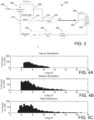
- FIG. 3 illustrates an embodiment of the AVAPS system that supports variable ventilation.
- the AVAPS method 300 receives the target volume Vtarget 305.
- a VV distribution function 360 produces a variable target volume with Vtarget as the mean value.
- the AVAPS method 300 computes the volume error Verr as the difference (using adder 310) between the measured tidal volume Vt and the variable target volume on each breath.
- a divider 315 divides the error Verror in half. It is noted that the error Verror may be divided by other values as well to provide stability and robustness in the presence of noise or disturbances. This factor determines the gain of the adjustment controller.
- An adder 365 further determines the change in target volume by subtracting the previous target volume value Vtarget n-1 from the current variable target value.
- An adder 370 adds the difference value output by the adder 365 to the output of the divider 315. The output of the adder 370 is then attenuated by the ventilator's best estimate of the dynamic compliance dyn C using the attenuator 320 to result in a change in pressure support ⁇ PS to be applied to achieve the change in volume.
- An adder 330 adds pressure support change ⁇ PS to the previous pressure support value PS n- 1 . The updated pressure support value is then limited 335 based upon the minimum and maximum pressure support values allowed for the user.
- This limited pressure support value is then used to generate a breath profile to deliver the specified pressure support and positive end-expiratory pressure (PEEP) 345.
- PEEP positive end-expiratory pressure
- a rise time filter 350 may be used to further smooth the waveform used to generate the breath, and the rise time filter 350 may be, for example, a low pass filter.
- the lung is monitored and the tidal volume Vt is measured 355, and this is the value that is fed back to the adder 310.
- the speed limiter of the AVAPS system 200 in FIG. 2 is removed in the AVAPS system 300 to allow volume to vary breath to breath, but the main components including the pressure limiter are otherwise preserved.
- the target is no longer a constant volume, but a volume that is varied according to the prescribed distribution function.
- FIGs. 4A, 4B, and 4C are histogram plots of the number of breaths per 1000 breaths at various volumes Vt for narrow, medium, and wide distributions, respectively.
- the distribution functions vary the breath over a 1000 breath sequence and a histogram of the normalized volumes in cc/kg ideal body weight (IBW) as shown in FIGs. 4A, 4B, and 4C .
- IBW ideal body weight
- These various distributions were used to simulate the operation of the AVAPS system 300 as shown in FIG. 3 .
- Each of the three distributions have a mean value of 8 cc / kg.
- the target volume Vtarget 305 should be normalized to this ratio. Note that in the medium and the wide distributions there are more large volumes selected than in the narrow distribution.
- FIGs. 5A, 5B, and 5C illustrate simulated results of the AVAPS system 300 using the narrow distribution of FIG. 4A on a passive lung.
- FIG. 5A is a plot of normalized volume versus breath number for both the target VV (VVtarg) and the actual volume. VVtarg is represented by the circles on the plot, and the actual volume is shown by the x's on the plot.
- FIG. 5B is the pressure support provided by the AVAPS system 300 on each breath. The pressure support varied from about 15 to about 25 cm H20. Also note that the values vary largely from breath to breath, and this is possible because three is no speed limit function in the AVAPS system 300.
- FIG. 5C is a histogram of the number of breaths at each normalized measured lung volume. An analysis of this data shows that a mean tidal volume of 300.1 ml is obtained as compared to the Vtarget of 300 ml.
- the AVAPS system 300 achieved the desired mean Vtarget value. Because a passive test lung was used, this is an easy situation for providing the needed pressure support to obtain the desired volume on each breath. The use of the passive lung does accurately model neuromuscular patients because they do not have a large respiratory drive.
- the AVAPS system 300 can maintain the average tidal volume because of the extra control loop in the AVAPS system 300.
- FIG. 6A is a plot of normalized volume versus breath number for both the target VV (Vtarg) and the actual volume. As before, VVtarg is represented by the circles on the plot, and the actual volume is shown by the x's on the plot.
- FIG. 6B is the pressure support provided by the AVAPS system 300 on each breath.
- FIG. 6C is a histogram of the number of breaths at each normalized measured lung volume. An analysis of this data shows that a mean tidal volume of 300.3 ml is obtained as compared to the Vtarget of 300 ml. Again, the AVAPS system 300 achieved the desired mean Vtarget value.
- FIG. 7A is a plot of normalized volume versus breath number for both the target VV (Vtarg) and the actual volume. As before, VVtarg is represented by the circles on the plot, and the actual volume is shown by the x's on the plot.
- FIG. 7B is the pressure support provided by the AVAPS system 300 on each breath.
- FIG. 7C is a histogram of the number of breaths at each normalized measured lung volume. An analysis of this data shows that a mean tidal volume of 299.9 ml is obtained as compared to the Vtarget of 300 ml. Again, the AVAPS system 300 achieved the desired mean Vtarget value.
- the AVAPS system 300 may be implemented using hardware to carry out the specific functions shown in FIG. 3 .
- This hardware may be an integrated circuit that receives the various input data and provides the control outputs to the ventilator.
- FIG. 8 illustrates an exemplary hardware diagram 800 for the AVAPS system of FIG. 3 .
- the device 800 includes a processor 820, memory 830, user interface 840, network interface 850, and storage 860 interconnected via one or more system buses 810. It will be understood that FIG. 8 constitutes, in some respects, an abstraction and that the actual organization of the components of the device 800 may be more complex than illustrated.
- the processor 820 may be any hardware device capable of executing instructions stored in memory 830 or storage 860 or otherwise processing data.
- the processor may include a microprocessor, a graphics processing unit (GPU), field programmable gate array (FPGA), application-specific integrated circuit (ASIC), any processor capable of parallel computing, or other similar devices.
- the processor may also be a special processor that implements machine learning models.
- the memory 830 may include various memories such as, for example L1, L2, or L3 cache or system memory. As such, the memory 830 may include static random-access memory (SRAM), dynamic RAM (DRAM), flash memory, read only memory (ROM), or other similar memory devices.
- SRAM static random-access memory
- DRAM dynamic RAM
- ROM read only memory
- the user interface 840 may include one or more devices for enabling communication with a user and may present information to users.
- the user interface 840 may include a display, a touch interface, a mouse, and/or a keyboard for receiving user commands.
- the user interface 840 may include a command line interface or graphical user interface that may be presented to a remote terminal via the network interface 850.
- the network interface 850 may include one or more devices for enabling communication with other hardware devices.
- the network interface 850 may include a network interface card (NIC) configured to communicate according to the Ethernet protocol or other communications protocols, including wireless protocols.
- NIC network interface card
- the network interface 850 may implement a TCP/IP stack for communication according to the TCP/IP protocols.
- TCP/IP protocols Various alternative or additional hardware or configurations for the network interface 850 will be apparent.
- the storage 860 may include one or more machine-readable storage media such as read-only memory (ROM), random-access memory (RAM), magnetic disk storage media, optical storage media, flash-memory devices, or similar storage media.
- the storage 860 may store instructions for execution by the processor 820 or data upon which the processor 820 may operate.
- the storage 860 may store a base operating system 861 for controlling various basic operations of the hardware 800.
- the storage 862 may store instructions for implementing the AVAPS system.
- the memory 830 may also be considered to constitute a “storage device” and the storage 860 may be considered a “memory.” Various other arrangements will be apparent. Further, the memory 830 and storage 860 may both be considered to be “non-transitory machine-readable media.” As used herein, the term “non-transitory” will be understood to exclude transitory signals but to include all forms of storage, including both volatile and non-volatile memories.
- the various components may be duplicated in various embodiments.
- the processor 820 may include multiple microprocessors that are configured to independently execute the methods described herein or are configured to perform steps or subroutines of the methods described herein such that the multiple processors cooperate to achieve the functionality described herein. Such plurality of processors may be of the same or different types.
- the various hardware components may belong to separate physical systems.
- the processor 820 may include a first processor in a first server and a second processor in a second server.
- variable volume ventilation provides a technological improvement over prior AVAPS systems by allowing for variable volume ventilation to be used along with AVAPS.
- variable volume ventilation has various benefits to the patient and combines these benefits with the benefits of AVAPS. Accordingly, a better ventilation therapy may be provided to the patient.
- non-transitory machine-readable storage medium will be understood to exclude a transitory propagation signal but to include all forms of volatile and non-volatile memory.
Landscapes
- Health & Medical Sciences (AREA)
- Public Health (AREA)
- General Health & Medical Sciences (AREA)
- Engineering & Computer Science (AREA)
- Biomedical Technology (AREA)
- Emergency Medicine (AREA)
- Heart & Thoracic Surgery (AREA)
- Hematology (AREA)
- Life Sciences & Earth Sciences (AREA)
- Animal Behavior & Ethology (AREA)
- Pulmonology (AREA)
- Anesthesiology (AREA)
- Veterinary Medicine (AREA)
- Nuclear Medicine, Radiotherapy & Molecular Imaging (AREA)
- Surgery (AREA)
- Urology & Nephrology (AREA)
- Epidemiology (AREA)
- Medical Informatics (AREA)
- Primary Health Care (AREA)
- Measurement Of The Respiration, Hearing Ability, Form, And Blood Characteristics Of Living Organisms (AREA)
Description
- Various exemplary embodiments disclosed herein relate generally to a system and method for delivering variable ventilation with average volume assured pressure support (AVAPS).
- Variable ventilation has been clinically proven to improve cell health in mechanically ventilated patients. This mode of ventilation intentionally varies the size of individual breaths but keeps the average breath size constant. AVAPS is a mode that allows volume target ventilation to be delivered to chronic patients with an noninvasive ventilation (NIV) interface. AVAPS is beneficial for spontaneously breathing patients because it limits the pressure and does not over-react to occasional events like swallowing, coughing, glottic closure, speaking, and movement.
- The invention is defined in
independent claim 1. Preferred embodiments are disclosed in the dependent claims. - A summary of various exemplary embodiments is presented below. Some simplifications and omissions may be made in the following summary, which is intended to highlight and introduce some aspects of the various exemplary embodiments, but not to limit the scope of the disclosure. Detailed descriptions of an exemplary embodiment adequate to allow those of ordinary skill in the art to make and use the inventive concepts will follow in later sections.
- Various embodiments relate to a method for controlling a ventilator to provide variable volume (VV) with average volume assured pressure support (AVAPS), including: producing a VV target volume using a VV distribution function; producing a volume error Verror that is the difference between the VV target volume and a measured volume of the previous breath; scaling the volume error Verror; producing a VV target difference as the difference between VV target volume and the VV target volume of the previous breath; producing a modified volume error by adding the VV target difference to the scaled volume error Verror; producing a delta pressure support ΔPS based upon the modified volume error and a dynamic compliance; and producing a current pressure support value based upon the delta pressure support ΔPS and the pressure support value of the previous breath.
- Various embodiments are described, wherein producing a delta pressure support ΔPS further comprises dividing the modified volume error by the dynamic compliance.
- Various embodiments are described, wherein the volume error Verror is scaled by a factor of 2.
- Various embodiments are described, further comprising limiting the current pressure support by a minimum pressure support value and a maximum pressure support value.
- Various embodiments are described, further comprising generating a breath profile based upon the current pressure support and a positive end-expiratory pressure (PEEP) value.
- Various embodiments are described, further comprising rise time filtering the breath profile.
- Various embodiments are described, further comprising applying the breath profile to a user's lung and measuring a volume of the resulting breath.
- Various embodiments are described, wherein the VV distribution function has a mean value based upon a received target volume value.
- Various embodiments are described, wherein the VV distribution function may be selected from a plurality of different VV distribution functions.
- Further various embodiments relate to a controller configured to control a ventilator to provide variable volume (VV) with average volume assured pressure support (AVAPS), including: a memory; a processor coupled to the memory, wherein the processor is further configured to: produce a VV target volume using a VV distribution function; produce a volume error Verror that is the difference between the VV target volume and a measured volume of the previous breath; scale the volume error Verror; produce a VV target difference as the difference between VV target volume and the VV target volume of the previous breath; produce a modified volume error by adding the VV target difference to the scaled volume error Verror; produce a delta pressure support ΔPS based upon the modified volume error and a dynamic compliance; and produce a current pressure support value based upon the delta pressure support ΔPS and the pressure support value of the previous breath.
- Various embodiments are described, wherein producing a delta pressure support ΔPS further comprises dividing the modified volume error by the dynamic compliance.
- Various embodiments are described, wherein the volume error Verror is scaled by a factor of 2.
- Various embodiments are described, wherein the processor is further configured to limit the current pressure support by a minimum pressure support value and a maximum pressure support value.
- Various embodiments are described, wherein the processor is further configured to generate a breath profile based upon the current pressure support and a positive end-expiratory pressure (PEEP) value.
- Various embodiments are described, wherein the processor is further configured to rise time filter the breath profile.
- Various embodiments are described, wherein the processor is further configured to apply the breath profile to a user's lung and measuring a volume of the resulting breath.
- Various embodiments are described, wherein the VV distribution function has a mean value based upon a received target volume value.
- Various embodiments are described, wherein the VV distribution function may be selected from a plurality of different VV distribution functions.
- In order to better understand various exemplary embodiments, reference is made to the accompanying drawings, wherein:
-
FIG. 1 illustrates a plot of lung volume vs pressure showing the variable loops that are made during VV with AVAPS along with the variable pressure support. -
FIG. 2 illustrates a block diagram of the AVAPS control method; -
FIG. 3 illustrates an embodiment of the AVAPS system that supports variable ventilation; -
FIGs. 4A, 4B, and 4C are histogram plots of the number of breaths per 1000 breaths at various volumes Vt for narrow, medium, and wide distributions respectively; -
FIGs. 5A, 5B, and 5C illustrate simulated results of the AVAPS system using the narrow distribution ofFIG. 4A on a passive lung; -
FIGs. 6A, 6B, and 6C illustrate simulated results of the AVAPS system using the narrow distribution ofFIG. 4A using assisted breaths with a fixed frequency and fixed muscle effort; -
FIGs. 7A, 7B, and 7C illustrate simulated results of theAVAPS system 300 using the wide distribution ofFIG. 4C using assisted breaths with a fixed frequency and fixed muscle effort; and -
FIG. 8 illustrates an exemplary hardware diagram for the AVAPS system ofFIG. 3 . - To facilitate understanding, identical reference numerals have been used to designate elements having substantially the same or similar structure and/or substantially the same or similar function.
- The description and drawings illustrate the principles of the invention. It will thus be appreciated that those skilled in the art will be able to devise various arrangements that, although not explicitly described or shown herein, embody the principles of the disclosure and are included within its scope. Additionally, the term, "or," as used herein, refers to a non-exclusive or (i.e., and/or), unless otherwise indicated (e.g., "or else" or "or in the alternative"). Also, the various embodiments described herein are not necessarily mutually exclusive, as some embodiments can be combined with one or more other embodiments to form new embodiments.
- Variable ventilation delivers tidal volumes (TV) that vary from breath to breath around a prescribed average TV in accordance with a predefined statistical distribution.
FIG. 1 illustrates aplot 100 of 1000 variable volume breaths illustrated by varying the pressure support. Theplot 100 includesline 120 that illustrates the general relationship between pressure and volume for the lung from total collapse to full distension. Theplot 100 shows thevarious PV loops 105 that are produced by this manner of ventilation, where each loop illustrates the pressure and volume values during a breath. Theinset plot 110 shows a histogram of how TV is distributed over a 1000 breath sequence. For conventional mechanical ventilation (MV) adotted loop 130 is shown where the TV is a constant value CV. The pressure support required to produce this constant values is shown as adotted line 125 inplot 115. For VV, the vertical bars inplot 115 shows how the pressure support for each breath varies to produce the desired variation in TV according to the distribution function, 110 and the relationship between pressure andvolume 120. More specifically, VV delivers variable TVs with each breath with the mean equal to the TV that would be prescribed in conventional MV. The intuition behind this ventilation strategy comes from the observation that biological systems exhibit intrinsic fluctuations. Subsystems like the cardiovascular and respiratory systems exhibit variability even during steady-state conditions. Breath-by-breath variation in tidal volume and respiratory rate contribute to sustain fast state transition while minimizing the ratio between tissue stress and strain. The coefficient of variation in tidal volume in healthy spontaneous breathing at rest is approximately 33%. Lefevre et al. were the first to conjecture that the use of physiological variability in the respiratory pattern, as observed in the healthy resting state, may be beneficial in patients under controlled mechanical ventilation, to improve lung function and reduce injury in the diseased lung. (See Lefevre, G.R., et al., Improved arterial oxygenation after oleic acid lung injury in the pig using a computer-controlled mechanical ventilator. Am J Respir Crit Care Med, 1996. 154(5): p. 1567-72) - Further research has demonstrated that VV is superior to conventional MV currently in clinical use, with improved outcomes and reduced likelihood of ventilator-induce lung injury (VILI). VV delivers a specific set of TVs and respiratory frequencies (f) such that TVs are pulled from a specific probability distribution optimized to best recruit the lung's collapsed regions, and f is matched so that the delivered minute ventilation is constant. This research has illustrated that VV improves gas exchange and reduces lung injury compared to conventional MV. VV may use the following mechanisms to improve performance as compared to conventual MV: VV maintains an open lung; VV promotes surfactant production and release; and VV downregulates inflammation in the lung.
- In previous studies, VV has only been implemented in the acute setting with volume control ventilation (VCV) where the volume control setpoint is varied breath by breath according to the distribution profile of Suki, et al. (See Suki, B., et al., Life-support system benefits from noise. Nature, 1998. 393(6681): p. 127-8).
- Pressure control ventilation (PCV) has become the preferred method of chronically ventilated patients because it prevents barotrauma and discourages asynchrony during the periods of bulbar activity, cough, glottic movements and activity. Volume assured pressure support (VAPS) modes are a hybrid mix of the VCV and PCV where the ventilator will target a volume setpoint through successive small changes in pressure support, but maintain the control pressure within limits set by the clinician to optimize patient comfort and safety. VAPS has also been demonstrated to be effective in noninvasive ventilation because it has algorithms that are leak compensated and tolerant of variable leak. However, the slow reaction of VAPS to changing respiratory physiology makes it inherently difficult to target the programmed variation of the target volume Vt such as in VV unless the VAPS mode is modified at its core to support VV.
- Embodiments of an average volume assured pressure support (AVAPS) system are described that combines the algorithms of VV and AVAPS to produce a VV algorithm that performs as closely as possible to that demonstrated in previous studies with modified control ventilation (CV) for VV. The AVAPS system strives to maintain the comfort and protection and all of the other benefits of the VAPS mode in the chronic patient with the benefit of open lung and cell health of VV.
- AVAPS seeks to target a set tidal volume by adjusting pressure support in a systematic method.
FIG. 2 illustrates a block diagram of the AVAPS control method. First, theAVAPS method 200 computes the volume error Verr as the difference (using adder 210) between the measured tidal volume Vt and thetarget volume Vtarget 205 on each breath. Adivider 215 divides the error Verror in half. It is noted that the error Verror may be divided by other values as well to provide stability and robustness in the presence of noise or disturbances. This factor determines the gain of the adjustment controller. The output of thedivider 215 is then attenuated by the ventilator's best estimate of the dynamic compliance dyn C using theattenuator 220 to determine a change in pressure support ΔPS to be applied to achieve the change in volume. The dynamic compliance dyn C is defined as the change in lung volume per unit change in the pressure support. Aspeed limiter 225 limits the pressure support ΔPS so that ΔPS can only change so fast resulting in ΔPSlim. Anadder 230 adds limited pressure support ΔPSlim to the previous pressure support value PS n-1 . The updated pressure support value is then limited 235 based upon the minimum and maximum pressure support values allowed for the user. This limited pressure support value is then used to generate a breath profile to deliver the specified pressure support and positive end-expiratory pressure (PEEP) 245. For example, if the PEEP value of 5 cm H20 pressure with a PS of 12 cm H20 is specified, a breath profile that starts at 5 cm H20 pressure and rises to 17 cm H20 pressure will be generated. Arise time filter 250 may be used to further smooth the waveform used to generate the breath, and therise time filter 250 may be, for example, a low pass filter. The lung is monitored and the tidal volume Vt is measured 255, and this is the value that is fed back to theadder 210. - The relationship between tidal volume delivery and pressure support when updating the AVAPS method to accommodate variable ventilation will first be explained. The expected closed form relationship between flow in the inspiratory phase to a passive lung and pressure support is given by the following equation:

- The volume at the end of inspiration is approximated by the following equation:

- The above equation indicates that the volume delivered is linearly proportional to pressure support. Note that no closed form equation exists when the patient is active, but the assumption is that for neuromuscular patients, the majority of volume results from ventilator assistance.
- This implies that the
AVAPS method 200 ofFIG. 2 may be modified to support variable ventilation.FIG. 3 illustrates an embodiment of the AVAPS system that supports variable ventilation. First, theAVAPS method 300 receives thetarget volume Vtarget 305. AVV distribution function 360 produces a variable target volume with Vtarget as the mean value. TheAVAPS method 300 computes the volume error Verr as the difference (using adder 310) between the measured tidal volume Vt and the variable target volume on each breath. Adivider 315 divides the error Verror in half. It is noted that the error Verror may be divided by other values as well to provide stability and robustness in the presence of noise or disturbances. This factor determines the gain of the adjustment controller. Anadder 365 further determines the change in target volume by subtracting the previous target volume value Vtargetn-1 from the current variable target value. Anadder 370 adds the difference value output by theadder 365 to the output of thedivider 315. The output of theadder 370 is then attenuated by the ventilator's best estimate of the dynamic compliance dyn C using theattenuator 320 to result in a change in pressure support ΔPS to be applied to achieve the change in volume. Anadder 330 adds pressure support change ΔPS to the previous pressure support value PS n-1 . The updated pressure support value is then limited 335 based upon the minimum and maximum pressure support values allowed for the user. This limited pressure support value is then used to generate a breath profile to deliver the specified pressure support and positive end-expiratory pressure (PEEP) 345. For example, if the PEEP value of 5 cm H20 pressure with a PS of 12 cm H20 pressure is specified, a breath profile that starts at 5 cm H20 pressure and rises to 17 cm H20 pressure will be generated. Arise time filter 350 may be used to further smooth the waveform used to generate the breath, and therise time filter 350 may be, for example, a low pass filter. The lung is monitored and the tidal volume Vt is measured 355, and this is the value that is fed back to theadder 310. - It is noted that the speed limiter of the
AVAPS system 200 inFIG. 2 is removed in theAVAPS system 300 to allow volume to vary breath to breath, but the main components including the pressure limiter are otherwise preserved. The target is no longer a constant volume, but a volume that is varied according to the prescribed distribution function. - Professor Bela Suki of Boston University has produced 3 distribution functions to be considered for variable ventilation.
FIGs. 4A, 4B, and 4C are histogram plots of the number of breaths per 1000 breaths at various volumes Vt for narrow, medium, and wide distributions, respectively. The distribution functions vary the breath over a 1000 breath sequence and a histogram of the normalized volumes in cc/kg ideal body weight (IBW) as shown inFIGs. 4A, 4B, and 4C . These various distributions were used to simulate the operation of theAVAPS system 300 as shown inFIG. 3 . Each of the three distributions have a mean value of 8 cc / kg. Thetarget volume Vtarget 305 should be normalized to this ratio. Note that in the medium and the wide distributions there are more large volumes selected than in the narrow distribution. -
FIGs. 5A, 5B, and 5C illustrate simulated results of theAVAPS system 300 using the narrow distribution ofFIG. 4A on a passive lung. The following parameters were used in the simulation: R= 20; C = 20; and Vtarget = 300 ml.FIG. 5A is a plot of normalized volume versus breath number for both the target VV (VVtarg) and the actual volume. VVtarg is represented by the circles on the plot, and the actual volume is shown by the x's on the plot.FIG. 5B is the pressure support provided by theAVAPS system 300 on each breath. The pressure support varied from about 15 to about 25 cm H20. Also note that the values vary largely from breath to breath, and this is possible because three is no speed limit function in theAVAPS system 300. As can be seen in this situation the measured volume matches the VVtarget very well as the circles and x's on the plot align very closely.FIG. 5C is a histogram of the number of breaths at each normalized measured lung volume. An analysis of this data shows that a mean tidal volume of 300.1 ml is obtained as compared to the Vtarget of 300 ml. TheAVAPS system 300 achieved the desired mean Vtarget value. Because a passive test lung was used, this is an easy situation for providing the needed pressure support to obtain the desired volume on each breath. The use of the passive lung does accurately model neuromuscular patients because they do not have a large respiratory drive. - It is noted that when the patient is active, the same control over the tidal volumes does not result as with the passive lung. But the
AVAPS system 300 can maintain the average tidal volume because of the extra control loop in theAVAPS system 300. -
FIGs. 6A, 6B, and 6C illustrate simulated results of theAVAPS system 300 using the narrow distribution ofFIG. 4A using assisted breaths with a fixed frequency and fixed muscle effort. So in this situation the patient is taking some of the breaths on their own and being assisted on other breaths. The following parameters were used in the simulation: R= 20; C = 20; and Vtarget = 300 ml.FIG. 6A is a plot of normalized volume versus breath number for both the target VV (VVtarg) and the actual volume. As before, VVtarg is represented by the circles on the plot, and the actual volume is shown by the x's on the plot.FIG. 6B is the pressure support provided by theAVAPS system 300 on each breath. The pressure support varied from about 13 to about 23 cm H20. As can be seen in this situation, the measured volume is close to the VVtarget values, but there are some variation as can be seen where the circles and x's on the plot do not quite align.FIG. 6C is a histogram of the number of breaths at each normalized measured lung volume. An analysis of this data shows that a mean tidal volume of 300.3 ml is obtained as compared to the Vtarget of 300 ml. Again, theAVAPS system 300 achieved the desired mean Vtarget value. -
FIGs. 7A, 7B, and 7C illustrate simulated results of theAVAPS system 300 using the wide distribution ofFIG. 4C using assisted breaths with a fixed frequency and fixed muscle effort. So in this situation the patient is taking some of the breaths on their own and being assisted on other breaths. The following parameters were used in the simulation: R= 20; C = 20; and Vtarget = 300 ml.FIG. 7A is a plot of normalized volume versus breath number for both the target VV (VVtarg) and the actual volume. As before, VVtarg is represented by the circles on the plot, and the actual volume is shown by the x's on the plot.FIG. 7B is the pressure support provided by theAVAPS system 300 on each breath. The pressure support varied from about 11 to about 32 cm H20. As can be seen in this situation, the measured volume is close to the VVtarget values, but there are some variation as can be seen where the circles and x's on the plot do not quite align.FIG. 7C is a histogram of the number of breaths at each normalized measured lung volume. An analysis of this data shows that a mean tidal volume of 299.9 ml is obtained as compared to the Vtarget of 300 ml. Again, theAVAPS system 300 achieved the desired mean Vtarget value. - Various other simulations using the different patient parameters and distributions showed that the mean Vtarget values was within 1 ml of the Vtarget value of 300. This illustrates that the
AVAPS system 300 achieves the desired mean tidal volume. - The
AVAPS system 300 may be implemented using hardware to carry out the specific functions shown inFIG. 3 . This hardware may be an integrated circuit that receives the various input data and provides the control outputs to the ventilator. - The
AVAPS system 300 may also be implemented using a processor and software instructions on that processor to carry out the functions shown inFIG. 3 .FIG. 8 illustrates an exemplary hardware diagram 800 for the AVAPS system ofFIG. 3 . As shown, thedevice 800 includes aprocessor 820,memory 830,user interface 840,network interface 850, andstorage 860 interconnected via one or more system buses 810. It will be understood thatFIG. 8 constitutes, in some respects, an abstraction and that the actual organization of the components of thedevice 800 may be more complex than illustrated. - The
processor 820 may be any hardware device capable of executing instructions stored inmemory 830 orstorage 860 or otherwise processing data. As such, the processor may include a microprocessor, a graphics processing unit (GPU), field programmable gate array (FPGA), application-specific integrated circuit (ASIC), any processor capable of parallel computing, or other similar devices. The processor may also be a special processor that implements machine learning models. - The
memory 830 may include various memories such as, for example L1, L2, or L3 cache or system memory. As such, thememory 830 may include static random-access memory (SRAM), dynamic RAM (DRAM), flash memory, read only memory (ROM), or other similar memory devices. - The
user interface 840 may include one or more devices for enabling communication with a user and may present information to users. For example, theuser interface 840 may include a display, a touch interface, a mouse, and/or a keyboard for receiving user commands. In some embodiments, theuser interface 840 may include a command line interface or graphical user interface that may be presented to a remote terminal via thenetwork interface 850. - The
network interface 850 may include one or more devices for enabling communication with other hardware devices. For example, thenetwork interface 850 may include a network interface card (NIC) configured to communicate according to the Ethernet protocol or other communications protocols, including wireless protocols. Additionally, thenetwork interface 850 may implement a TCP/IP stack for communication according to the TCP/IP protocols. Various alternative or additional hardware or configurations for thenetwork interface 850 will be apparent. - The
storage 860 may include one or more machine-readable storage media such as read-only memory (ROM), random-access memory (RAM), magnetic disk storage media, optical storage media, flash-memory devices, or similar storage media. In various embodiments, thestorage 860 may store instructions for execution by theprocessor 820 or data upon which theprocessor 820 may operate. For example, thestorage 860 may store abase operating system 861 for controlling various basic operations of thehardware 800. Thestorage 862 may store instructions for implementing the AVAPS system. - It will be apparent that various information described as stored in the
storage 860 may be additionally or alternatively stored in thememory 830. In this respect, thememory 830 may also be considered to constitute a "storage device" and thestorage 860 may be considered a "memory." Various other arrangements will be apparent. Further, thememory 830 andstorage 860 may both be considered to be "non-transitory machine-readable media." As used herein, the term "non-transitory" will be understood to exclude transitory signals but to include all forms of storage, including both volatile and non-volatile memories. - While the
system 800 is shown as including one of each described component, the various components may be duplicated in various embodiments. For example, theprocessor 820 may include multiple microprocessors that are configured to independently execute the methods described herein or are configured to perform steps or subroutines of the methods described herein such that the multiple processors cooperate to achieve the functionality described herein. Such plurality of processors may be of the same or different types. Further, where thedevice 800 is implemented in a cloud computing system, the various hardware components may belong to separate physical systems. For example, theprocessor 820 may include a first processor in a first server and a second processor in a second server. - The AVAPS system described herein provides a technological improvement over prior AVAPS systems by allowing for variable volume ventilation to be used along with AVAPS. As described above the use of variable volume ventilation has various benefits to the patient and combines these benefits with the benefits of AVAPS. Accordingly, a better ventilation therapy may be provided to the patient.
- Any combination of specific software running on a processor to implement the embodiments of the invention, constitute a specific dedicated machine.
- As used herein, the term "non-transitory machine-readable storage medium" will be understood to exclude a transitory propagation signal but to include all forms of volatile and non-volatile memory.
- As is readily apparent to those skilled in the art, variations and modifications can be affected while remaining within the scope of the invention. Accordingly, the foregoing disclosure, description, and figures are for illustrative purposes only and do not in any way limit the invention, which is defined only by the claims.
Claims (10)
- A controller configured to control a ventilator to provide variable volume VV with average volume assured pressure support AVAPS, comprising:a memory (830);a processor (820) coupled to the memory, wherein the processor is further configured to:produce a VV target volume using a VV distribution function;produce a volume error Verror that is the difference between the VV target volume and a measured volume of the previous breath;scale the volume error Verror;produce a VV target difference as the difference between VV target volume and the VV target volume of the previous breath;produce a modified volume error by adding the VV target difference to the scaled volume error Verror;produce a delta pressure support ΔPS based upon the modified volume error and a dynamic compliance; andproduce a current pressure support value based upon the delta pressure support ΔPS and the pressure support value of the previous breath.
- The controller of claim 1, wherein producing a delta pressure support ΔPS further comprises dividing the modified volume error by the dynamic compliance.
- The controller of claim 2, wherein the volume error Verror is scaled by a factor of 2.
- The controller of claim 1, wherein the processor (820) is further configured to limit the current pressure support by a minimum pressure support value and a maximum pressure support value.
- The controller of claim 1, wherein the processor (820) is further configured to generate a breath profile based upon the current pressure support and a positive end-expiratory pressure PEEP value.
- The controller of claim 5, wherein the processor (820) is further configured to rise time filter the breath profile.
- The controller of claim 6, wherein the processor (820) is further configured to apply the breath profile to a user's lung and measuring a volume of the resulting breath.
- The controller of claim 1, wherein the VV distribution function has a mean value based upon a received target volume value.
- The controller of claim 1, wherein the VV distribution function may be selected from a plurality of different VV distribution functions.
- A ventilator for delivering variable ventilation with average volume assured pressure support (AVAPS) comprising a controller as claimed in any of claims 1 to 9.
Applications Claiming Priority (2)
| Application Number | Priority Date | Filing Date | Title |
|---|---|---|---|
| US202063037620P | 2020-06-11 | 2020-06-11 | |
| PCT/EP2021/065402 WO2021250066A1 (en) | 2020-06-11 | 2021-06-09 | Method of delivering variable ventilation with avaps cross-reference to related applications |
Publications (2)
| Publication Number | Publication Date |
|---|---|
| EP4164717A1 EP4164717A1 (en) | 2023-04-19 |
| EP4164717B1 true EP4164717B1 (en) | 2024-08-07 |
Family
ID=76483286
Family Applications (1)
| Application Number | Title | Priority Date | Filing Date |
|---|---|---|---|
| EP21732840.0A Active EP4164717B1 (en) | 2020-06-11 | 2021-06-09 | Controller and ventilator to provide variable volume (vv) with average volume assured pressure support (avaps) |
Country Status (4)
| Country | Link |
|---|---|
| US (1) | US12233210B2 (en) |
| EP (1) | EP4164717B1 (en) |
| CN (1) | CN115768507B (en) |
| WO (1) | WO2021250066A1 (en) |
Family Cites Families (15)
| Publication number | Priority date | Publication date | Assignee | Title |
|---|---|---|---|---|
| BR9304638A (en) | 1993-12-06 | 1995-07-25 | Intermed Equipamento Medico Ho | Respiratory cycle control system |
| NZ599296A (en) * | 2003-11-26 | 2013-07-26 | Resmed Ltd | Apparatus for providing pressurized ventilatory assistance to a patient |
| US7886739B2 (en) * | 2005-10-11 | 2011-02-15 | Carefusion 207, Inc. | System and method for circuit compliance compensated volume control in a patient respiratory ventilator |
| US7918223B2 (en) * | 2005-11-09 | 2011-04-05 | Carefusion 207, Inc. | System and method for circuit compliance compensated pressure-regulated volume control in a patient respiratory ventilator |
| US8973578B2 (en) | 2006-09-14 | 2015-03-10 | Politecnico Di Milano | Apparatus for respiratory support and non-invasive detection of alveolar derecruitment for patients suffering from respiratory failure |
| JP5432728B2 (en) * | 2007-03-16 | 2014-03-05 | コーニンクレッカ フィリップス エヌ ヴェ | Apparatus for evaluation of respiratory motion recording data and gas exchange data |
| US8272380B2 (en) * | 2008-03-31 | 2012-09-25 | Nellcor Puritan Bennett, Llc | Leak-compensated pressure triggering in medical ventilators |
| JP5715066B2 (en) * | 2008-12-19 | 2015-05-07 | コーニンクレッカ フィリップス エヌ ヴェ | System and method for treating lung disease using positive airway pressure support |
| DE102009041247A1 (en) * | 2009-09-04 | 2011-03-24 | Technische Universität Dresden | Method for pressure-controlled respiration for securing gas exchange in critically ill patient, involves forming distribution of airway volumes with middle value, and monitoring regulation of application of distribution of volumes |
| US8607789B2 (en) | 2010-06-30 | 2013-12-17 | Covidien Lp | Ventilator-initiated prompt regarding auto-PEEP detection during volume ventilation of non-triggering patient exhibiting obstructive component |
| BR112013012427B1 (en) * | 2010-11-23 | 2021-05-04 | Koninklijke Philips N.V. | system configured to release a pressurized flow of breathable gas into an individual's airway |
| US9675771B2 (en) * | 2013-10-18 | 2017-06-13 | Covidien Lp | Methods and systems for leak estimation |
| US10183139B2 (en) | 2014-04-11 | 2019-01-22 | Vyaire Medical Capital Llc | Methods for controlling mechanical lung ventilation |
| US20160287824A1 (en) * | 2015-04-03 | 2016-10-06 | Invent Medical Corporation | Ventilator |
| US20210393902A1 (en) * | 2020-06-23 | 2021-12-23 | Covidien Lp | One-touch ventilation mode |
-
2021
- 2021-05-11 US US17/317,031 patent/US12233210B2/en active Active
- 2021-06-09 CN CN202180041776.6A patent/CN115768507B/en active Active
- 2021-06-09 EP EP21732840.0A patent/EP4164717B1/en active Active
- 2021-06-09 WO PCT/EP2021/065402 patent/WO2021250066A1/en not_active Ceased
Also Published As
| Publication number | Publication date |
|---|---|
| US20210386948A1 (en) | 2021-12-16 |
| CN115768507B (en) | 2025-10-21 |
| CN115768507A (en) | 2023-03-07 |
| US12233210B2 (en) | 2025-02-25 |
| EP4164717A1 (en) | 2023-04-19 |
| WO2021250066A1 (en) | 2021-12-16 |
Similar Documents
| Publication | Publication Date | Title |
|---|---|---|
| US11638796B2 (en) | Methods and systems for exhalation control and trajectory optimization | |
| Johnson et al. | Treatment of sleep-disordered breathing with positive airway pressure devices: technology update | |
| EP2349420B1 (en) | Inversion-based feed-forward compensation of inspiratory trigger dynamics in medical ventilators | |
| EP1005830B1 (en) | Assisted ventilation to match patient respiratory need | |
| US9492629B2 (en) | Methods and systems for ventilation with unknown exhalation flow and exhalation pressure | |
| EP3362131B1 (en) | Mechanical ventilation with automatic control of patient's work of breathing using classical feedback control | |
| JP2010246952A (en) | Synchronizing patient and ventilator using two phase sensors | |
| AU2012243429A1 (en) | System and process for determining a positive end-expiratory pressure for a mechanical ventilation system | |
| EP3129090B1 (en) | A method for controlling mechanical lung ventilation | |
| Pomprapa et al. | Funnel control for oxygenation during artificial ventilation therapy | |
| CN105457135B (en) | Ventilator pressure method of adjustment, device and ventilator | |
| US12233210B2 (en) | Method of delivering variable ventilation with AVAPS | |
| WO2022066495A1 (en) | Synchronized high-flow system | |
| Rocco et al. | Modelling the mechanical effects of tracheal tubes in normal subjects | |
| Gallagher | Alternative modes of mechanical ventilation | |
| Jafari et al. | Robust feedback design for proportional assist ventilation-system dynamics and problem definition | |
| CN117122781A (en) | Output pressure adjusting method for respiratory support equipment | |
| EP1810708B1 (en) | Patient-ventilator synchronization using dual phase sensors | |
| Thakur et al. | Auto-Mode Shifting: A Machine Learning-Based Automatic Ventilation Mode Selection Technique Personalized to Physiological Characteristics of Intubated Patients | |
| RRT-NPS | RRT-ACCS RPFT AE-C FAARC | |
| Guide | Contact: pneuma. bmsr@ gmail. com | |
| CN118320241A (en) | An adaptive variability ventilation method, system and ventilator | |
| CN117653844A (en) | An active positive end-expiratory pressure adjustment method and system |
Legal Events
| Date | Code | Title | Description |
|---|---|---|---|
| STAA | Information on the status of an ep patent application or granted ep patent |
Free format text: STATUS: UNKNOWN |
|
| STAA | Information on the status of an ep patent application or granted ep patent |
Free format text: STATUS: THE INTERNATIONAL PUBLICATION HAS BEEN MADE |
|
| PUAI | Public reference made under article 153(3) epc to a published international application that has entered the european phase |
Free format text: ORIGINAL CODE: 0009012 |
|
| STAA | Information on the status of an ep patent application or granted ep patent |
Free format text: STATUS: REQUEST FOR EXAMINATION WAS MADE |
|
| 17P | Request for examination filed |
Effective date: 20230111 |
|
| AK | Designated contracting states |
Kind code of ref document: A1 Designated state(s): AL AT BE BG CH CY CZ DE DK EE ES FI FR GB GR HR HU IE IS IT LI LT LU LV MC MK MT NL NO PL PT RO RS SE SI SK SM TR |
|
| DAV | Request for validation of the european patent (deleted) | ||
| DAX | Request for extension of the european patent (deleted) | ||
| REG | Reference to a national code |
Ref country code: DE Ref legal event code: R079 Free format text: PREVIOUS MAIN CLASS: A61M0016000000 Ipc: G16H0020400000 Ref country code: DE Ref legal event code: R079 Ref document number: 602021016864 Country of ref document: DE Free format text: PREVIOUS MAIN CLASS: A61M0016000000 Ipc: G16H0020400000 |
|
| GRAP | Despatch of communication of intention to grant a patent |
Free format text: ORIGINAL CODE: EPIDOSNIGR1 |
|
| STAA | Information on the status of an ep patent application or granted ep patent |
Free format text: STATUS: GRANT OF PATENT IS INTENDED |
|
| RIC1 | Information provided on ipc code assigned before grant |
Ipc: A61M 16/00 20060101ALI20240123BHEP Ipc: G16H 20/40 20180101AFI20240123BHEP |
|
| INTG | Intention to grant announced |
Effective date: 20240205 |
|
| GRAS | Grant fee paid |
Free format text: ORIGINAL CODE: EPIDOSNIGR3 |
|
| GRAA | (expected) grant |
Free format text: ORIGINAL CODE: 0009210 |
|
| STAA | Information on the status of an ep patent application or granted ep patent |
Free format text: STATUS: THE PATENT HAS BEEN GRANTED |
|
| AK | Designated contracting states |
Kind code of ref document: B1 Designated state(s): AL AT BE BG CH CY CZ DE DK EE ES FI FR GB GR HR HU IE IS IT LI LT LU LV MC MK MT NL NO PL PT RO RS SE SI SK SM TR |
|
| REG | Reference to a national code |
Ref country code: GB Ref legal event code: FG4D |
|
| REG | Reference to a national code |
Ref country code: CH Ref legal event code: EP |
|
| REG | Reference to a national code |
Ref country code: IE Ref legal event code: FG4D |
|
| REG | Reference to a national code |
Ref country code: DE Ref legal event code: R096 Ref document number: 602021016864 Country of ref document: DE |
|
| REG | Reference to a national code |
Ref country code: LT Ref legal event code: MG9D |
|
| REG | Reference to a national code |
Ref country code: NL Ref legal event code: MP Effective date: 20240807 |
|
| PG25 | Lapsed in a contracting state [announced via postgrant information from national office to epo] |
Ref country code: NO Free format text: LAPSE BECAUSE OF FAILURE TO SUBMIT A TRANSLATION OF THE DESCRIPTION OR TO PAY THE FEE WITHIN THE PRESCRIBED TIME-LIMIT Effective date: 20241107 |
|
| REG | Reference to a national code |
Ref country code: AT Ref legal event code: MK05 Ref document number: 1711891 Country of ref document: AT Kind code of ref document: T Effective date: 20240807 |
|
| PG25 | Lapsed in a contracting state [announced via postgrant information from national office to epo] |
Ref country code: NL Free format text: LAPSE BECAUSE OF FAILURE TO SUBMIT A TRANSLATION OF THE DESCRIPTION OR TO PAY THE FEE WITHIN THE PRESCRIBED TIME-LIMIT Effective date: 20240807 Ref country code: PL Free format text: LAPSE BECAUSE OF FAILURE TO SUBMIT A TRANSLATION OF THE DESCRIPTION OR TO PAY THE FEE WITHIN THE PRESCRIBED TIME-LIMIT Effective date: 20240807 Ref country code: GR Free format text: LAPSE BECAUSE OF FAILURE TO SUBMIT A TRANSLATION OF THE DESCRIPTION OR TO PAY THE FEE WITHIN THE PRESCRIBED TIME-LIMIT Effective date: 20241108 Ref country code: FI Free format text: LAPSE BECAUSE OF FAILURE TO SUBMIT A TRANSLATION OF THE DESCRIPTION OR TO PAY THE FEE WITHIN THE PRESCRIBED TIME-LIMIT Effective date: 20240807 Ref country code: PT Free format text: LAPSE BECAUSE OF FAILURE TO SUBMIT A TRANSLATION OF THE DESCRIPTION OR TO PAY THE FEE WITHIN THE PRESCRIBED TIME-LIMIT Effective date: 20241209 |
|
| PG25 | Lapsed in a contracting state [announced via postgrant information from national office to epo] |
Ref country code: BG Free format text: LAPSE BECAUSE OF FAILURE TO SUBMIT A TRANSLATION OF THE DESCRIPTION OR TO PAY THE FEE WITHIN THE PRESCRIBED TIME-LIMIT Effective date: 20240807 |
|
| PG25 | Lapsed in a contracting state [announced via postgrant information from national office to epo] |
Ref country code: LV Free format text: LAPSE BECAUSE OF FAILURE TO SUBMIT A TRANSLATION OF THE DESCRIPTION OR TO PAY THE FEE WITHIN THE PRESCRIBED TIME-LIMIT Effective date: 20240807 |
|
| PG25 | Lapsed in a contracting state [announced via postgrant information from national office to epo] |
Ref country code: IS Free format text: LAPSE BECAUSE OF FAILURE TO SUBMIT A TRANSLATION OF THE DESCRIPTION OR TO PAY THE FEE WITHIN THE PRESCRIBED TIME-LIMIT Effective date: 20241207 Ref country code: AT Free format text: LAPSE BECAUSE OF FAILURE TO SUBMIT A TRANSLATION OF THE DESCRIPTION OR TO PAY THE FEE WITHIN THE PRESCRIBED TIME-LIMIT Effective date: 20240807 |
|
| PG25 | Lapsed in a contracting state [announced via postgrant information from national office to epo] |
Ref country code: HR Free format text: LAPSE BECAUSE OF FAILURE TO SUBMIT A TRANSLATION OF THE DESCRIPTION OR TO PAY THE FEE WITHIN THE PRESCRIBED TIME-LIMIT Effective date: 20240807 |
|
| PG25 | Lapsed in a contracting state [announced via postgrant information from national office to epo] |
Ref country code: RS Free format text: LAPSE BECAUSE OF FAILURE TO SUBMIT A TRANSLATION OF THE DESCRIPTION OR TO PAY THE FEE WITHIN THE PRESCRIBED TIME-LIMIT Effective date: 20241107 Ref country code: ES Free format text: LAPSE BECAUSE OF FAILURE TO SUBMIT A TRANSLATION OF THE DESCRIPTION OR TO PAY THE FEE WITHIN THE PRESCRIBED TIME-LIMIT Effective date: 20240807 |
|
| PG25 | Lapsed in a contracting state [announced via postgrant information from national office to epo] |
Ref country code: RS Free format text: LAPSE BECAUSE OF FAILURE TO SUBMIT A TRANSLATION OF THE DESCRIPTION OR TO PAY THE FEE WITHIN THE PRESCRIBED TIME-LIMIT Effective date: 20241107 Ref country code: PT Free format text: LAPSE BECAUSE OF FAILURE TO SUBMIT A TRANSLATION OF THE DESCRIPTION OR TO PAY THE FEE WITHIN THE PRESCRIBED TIME-LIMIT Effective date: 20241209 Ref country code: PL Free format text: LAPSE BECAUSE OF FAILURE TO SUBMIT A TRANSLATION OF THE DESCRIPTION OR TO PAY THE FEE WITHIN THE PRESCRIBED TIME-LIMIT Effective date: 20240807 Ref country code: NO Free format text: LAPSE BECAUSE OF FAILURE TO SUBMIT A TRANSLATION OF THE DESCRIPTION OR TO PAY THE FEE WITHIN THE PRESCRIBED TIME-LIMIT Effective date: 20241107 Ref country code: NL Free format text: LAPSE BECAUSE OF FAILURE TO SUBMIT A TRANSLATION OF THE DESCRIPTION OR TO PAY THE FEE WITHIN THE PRESCRIBED TIME-LIMIT Effective date: 20240807 Ref country code: LV Free format text: LAPSE BECAUSE OF FAILURE TO SUBMIT A TRANSLATION OF THE DESCRIPTION OR TO PAY THE FEE WITHIN THE PRESCRIBED TIME-LIMIT Effective date: 20240807 Ref country code: IS Free format text: LAPSE BECAUSE OF FAILURE TO SUBMIT A TRANSLATION OF THE DESCRIPTION OR TO PAY THE FEE WITHIN THE PRESCRIBED TIME-LIMIT Effective date: 20241207 Ref country code: HR Free format text: LAPSE BECAUSE OF FAILURE TO SUBMIT A TRANSLATION OF THE DESCRIPTION OR TO PAY THE FEE WITHIN THE PRESCRIBED TIME-LIMIT Effective date: 20240807 Ref country code: GR Free format text: LAPSE BECAUSE OF FAILURE TO SUBMIT A TRANSLATION OF THE DESCRIPTION OR TO PAY THE FEE WITHIN THE PRESCRIBED TIME-LIMIT Effective date: 20241108 Ref country code: FI Free format text: LAPSE BECAUSE OF FAILURE TO SUBMIT A TRANSLATION OF THE DESCRIPTION OR TO PAY THE FEE WITHIN THE PRESCRIBED TIME-LIMIT Effective date: 20240807 Ref country code: ES Free format text: LAPSE BECAUSE OF FAILURE TO SUBMIT A TRANSLATION OF THE DESCRIPTION OR TO PAY THE FEE WITHIN THE PRESCRIBED TIME-LIMIT Effective date: 20240807 Ref country code: BG Free format text: LAPSE BECAUSE OF FAILURE TO SUBMIT A TRANSLATION OF THE DESCRIPTION OR TO PAY THE FEE WITHIN THE PRESCRIBED TIME-LIMIT Effective date: 20240807 Ref country code: AT Free format text: LAPSE BECAUSE OF FAILURE TO SUBMIT A TRANSLATION OF THE DESCRIPTION OR TO PAY THE FEE WITHIN THE PRESCRIBED TIME-LIMIT Effective date: 20240807 |
|
| PG25 | Lapsed in a contracting state [announced via postgrant information from national office to epo] |
Ref country code: DK Free format text: LAPSE BECAUSE OF FAILURE TO SUBMIT A TRANSLATION OF THE DESCRIPTION OR TO PAY THE FEE WITHIN THE PRESCRIBED TIME-LIMIT Effective date: 20240807 Ref country code: SM Free format text: LAPSE BECAUSE OF FAILURE TO SUBMIT A TRANSLATION OF THE DESCRIPTION OR TO PAY THE FEE WITHIN THE PRESCRIBED TIME-LIMIT Effective date: 20240807 |
|
| PG25 | Lapsed in a contracting state [announced via postgrant information from national office to epo] |
Ref country code: EE Free format text: LAPSE BECAUSE OF FAILURE TO SUBMIT A TRANSLATION OF THE DESCRIPTION OR TO PAY THE FEE WITHIN THE PRESCRIBED TIME-LIMIT Effective date: 20240807 |
|
| PG25 | Lapsed in a contracting state [announced via postgrant information from national office to epo] |
Ref country code: CZ Free format text: LAPSE BECAUSE OF FAILURE TO SUBMIT A TRANSLATION OF THE DESCRIPTION OR TO PAY THE FEE WITHIN THE PRESCRIBED TIME-LIMIT Effective date: 20240807 |
|
| PG25 | Lapsed in a contracting state [announced via postgrant information from national office to epo] |
Ref country code: SK Free format text: LAPSE BECAUSE OF FAILURE TO SUBMIT A TRANSLATION OF THE DESCRIPTION OR TO PAY THE FEE WITHIN THE PRESCRIBED TIME-LIMIT Effective date: 20240807 |
|
| REG | Reference to a national code |
Ref country code: DE Ref legal event code: R097 Ref document number: 602021016864 Country of ref document: DE |
|
| PLBE | No opposition filed within time limit |
Free format text: ORIGINAL CODE: 0009261 |
|
| STAA | Information on the status of an ep patent application or granted ep patent |
Free format text: STATUS: NO OPPOSITION FILED WITHIN TIME LIMIT |
|
| PGFP | Annual fee paid to national office [announced via postgrant information from national office to epo] |
Ref country code: DE Payment date: 20250626 Year of fee payment: 5 |
|
| PGFP | Annual fee paid to national office [announced via postgrant information from national office to epo] |
Ref country code: GB Payment date: 20250617 Year of fee payment: 5 |
|
| 26N | No opposition filed |
Effective date: 20250508 |
|
| PG25 | Lapsed in a contracting state [announced via postgrant information from national office to epo] |
Ref country code: SE Free format text: LAPSE BECAUSE OF FAILURE TO SUBMIT A TRANSLATION OF THE DESCRIPTION OR TO PAY THE FEE WITHIN THE PRESCRIBED TIME-LIMIT Effective date: 20240807 |
|
| REG | Reference to a national code |
Ref country code: CH Ref legal event code: H13 Free format text: ST27 STATUS EVENT CODE: U-0-0-H10-H13 (AS PROVIDED BY THE NATIONAL OFFICE) Effective date: 20260127 |
|
| PG25 | Lapsed in a contracting state [announced via postgrant information from national office to epo] |
Ref country code: IT Free format text: LAPSE BECAUSE OF FAILURE TO SUBMIT A TRANSLATION OF THE DESCRIPTION OR TO PAY THE FEE WITHIN THE PRESCRIBED TIME-LIMIT Effective date: 20240807 |
|
| PG25 | Lapsed in a contracting state [announced via postgrant information from national office to epo] |
Ref country code: MC Free format text: LAPSE BECAUSE OF FAILURE TO SUBMIT A TRANSLATION OF THE DESCRIPTION OR TO PAY THE FEE WITHIN THE PRESCRIBED TIME-LIMIT Effective date: 20240807 |
|
| PG25 | Lapsed in a contracting state [announced via postgrant information from national office to epo] |
Ref country code: LU Free format text: LAPSE BECAUSE OF NON-PAYMENT OF DUE FEES Effective date: 20250609 |
|
| REG | Reference to a national code |
Ref country code: BE Ref legal event code: MM Effective date: 20250630 |
|
| PG25 | Lapsed in a contracting state [announced via postgrant information from national office to epo] |
Ref country code: IE Free format text: LAPSE BECAUSE OF NON-PAYMENT OF DUE FEES Effective date: 20250609 |
|
| PG25 | Lapsed in a contracting state [announced via postgrant information from national office to epo] |
Ref country code: RO Free format text: LAPSE BECAUSE OF FAILURE TO SUBMIT A TRANSLATION OF THE DESCRIPTION OR TO PAY THE FEE WITHIN THE PRESCRIBED TIME-LIMIT Effective date: 20240807 Ref country code: BE Free format text: LAPSE BECAUSE OF NON-PAYMENT OF DUE FEES Effective date: 20250630 |
|
| PG25 | Lapsed in a contracting state [announced via postgrant information from national office to epo] |
Ref country code: FR Free format text: LAPSE BECAUSE OF NON-PAYMENT OF DUE FEES Effective date: 20250630 |
|
| PG25 | Lapsed in a contracting state [announced via postgrant information from national office to epo] |
Ref country code: CH Free format text: LAPSE BECAUSE OF NON-PAYMENT OF DUE FEES Effective date: 20250630 |