EP4164464B1 - Cleaning device with detaching device - Google Patents
Cleaning device with detaching device Download PDFInfo
- Publication number
- EP4164464B1 EP4164464B1 EP21730898.0A EP21730898A EP4164464B1 EP 4164464 B1 EP4164464 B1 EP 4164464B1 EP 21730898 A EP21730898 A EP 21730898A EP 4164464 B1 EP4164464 B1 EP 4164464B1
- Authority
- EP
- European Patent Office
- Prior art keywords
- cleaning
- detaching
- handle
- longitudinal axis
- cleaning head
- Prior art date
- Legal status (The legal status is an assumption and is not a legal conclusion. Google has not performed a legal analysis and makes no representation as to the accuracy of the status listed.)
- Active
Links
Images


Classifications
-
- A—HUMAN NECESSITIES
- A47—FURNITURE; DOMESTIC ARTICLES OR APPLIANCES; COFFEE MILLS; SPICE MILLS; SUCTION CLEANERS IN GENERAL
- A47L—DOMESTIC WASHING OR CLEANING; SUCTION CLEANERS IN GENERAL
- A47L13/00—Implements for cleaning floors, carpets, furniture, walls, or wall coverings
- A47L13/10—Scrubbing; Scouring; Cleaning; Polishing
- A47L13/20—Mops
- A47L13/24—Frames for mops; Mop heads
- A47L13/254—Plate frames
- A47L13/256—Plate frames for mops made of cloth
-
- A—HUMAN NECESSITIES
- A47—FURNITURE; DOMESTIC ARTICLES OR APPLIANCES; COFFEE MILLS; SPICE MILLS; SUCTION CLEANERS IN GENERAL
- A47L—DOMESTIC WASHING OR CLEANING; SUCTION CLEANERS IN GENERAL
- A47L13/00—Implements for cleaning floors, carpets, furniture, walls, or wall coverings
- A47L13/10—Scrubbing; Scouring; Cleaning; Polishing
- A47L13/16—Cloths; Pads; Sponges
-
- A—HUMAN NECESSITIES
- A47—FURNITURE; DOMESTIC ARTICLES OR APPLIANCES; COFFEE MILLS; SPICE MILLS; SUCTION CLEANERS IN GENERAL
- A47L—DOMESTIC WASHING OR CLEANING; SUCTION CLEANERS IN GENERAL
- A47L13/00—Implements for cleaning floors, carpets, furniture, walls, or wall coverings
- A47L13/10—Scrubbing; Scouring; Cleaning; Polishing
- A47L13/20—Mops
- A47L13/24—Frames for mops; Mop heads
- A47L13/254—Plate frames
- A47L13/257—Plate frames for mops made of sponge material
-
- A—HUMAN NECESSITIES
- A47—FURNITURE; DOMESTIC ARTICLES OR APPLIANCES; COFFEE MILLS; SPICE MILLS; SUCTION CLEANERS IN GENERAL
- A47L—DOMESTIC WASHING OR CLEANING; SUCTION CLEANERS IN GENERAL
- A47L13/00—Implements for cleaning floors, carpets, furniture, walls, or wall coverings
- A47L13/10—Scrubbing; Scouring; Cleaning; Polishing
- A47L13/42—Details
- A47L13/44—Securing scouring-cloths to the brush or like body of the implement
-
- A—HUMAN NECESSITIES
- A47—FURNITURE; DOMESTIC ARTICLES OR APPLIANCES; COFFEE MILLS; SPICE MILLS; SUCTION CLEANERS IN GENERAL
- A47L—DOMESTIC WASHING OR CLEANING; SUCTION CLEANERS IN GENERAL
- A47L13/00—Implements for cleaning floors, carpets, furniture, walls, or wall coverings
- A47L13/10—Scrubbing; Scouring; Cleaning; Polishing
- A47L13/42—Details
- A47L13/46—Securing scouring or polishing cloths or sponges to the handles by gripping means, tongs, or the like
Definitions
- the present invention relates to a cleaning device according to claim 1 and to a method of manufacturing a cleaning device according to claim 14.
- Cleaning devices such as mops, brooms, brushes or the like are well-known in the art. In places such as bathrooms or kitchens it is furthermore often desired to apply moisture or even detergents for better removal of pollutants to the cleaning device.
- cleaning pads can be attached to certain cleaning devices, and wherein the moisture or detergent is applied to the surface or object to be cleaned via the cleaning pads. After cleaning the soiled cleaning pad is disposed and replaced by a new cleaning pad.
- US 2019/0387948 A1 discloses a cleaning tool comprising a handle to be gripped by a user and a body that is attached to the handle and to which a web is removably attachable.
- the body furthermore comprises a pushing unit that enables the user to remove the soiled web.
- the disadvantages associated with such a cleaning tool are the fact that a user must bend down to the body in order to actuate the pushing unit. Thereby the user comes into proximity with the soiled web which can be unpleasant and above all unhygienically for the user.
- a cleaning tool comprising a handle configured to be grippable by a user, a body having one side to which the handle is pivotably connected and the other side providing an attachment surface to and from which a web for cleaning is attachable and detachable.
- the cleaning tool furthermore comprises a pushing unit provided at the handle to be movable therealong, wherein when the web is attached to the attachment surface, the pushing unit is movable along the handle to separate the web from the attachment surface.
- a device for manually cleaning surfaces that is formed by a tubular body with an elbow-like bent end bearing a support flange of a elastically deformable material and provided with an opening, onto which a paper sheet can be applied for performing the cleaning operation. After being used, the sheet is expelled by actuating a flexible organ housed and axially movable inside the tubular body and provided at its other end with an enlarged portion.
- a cleaning device which cleaning device comprises a handle extending along a longitudinal axis and a cleaning head.
- the cleaning head is in connection with the handle.
- the cleaning head is pivotally in connection with the handle.
- the cleaning head is configured such that a cleaning pad is detachably fastenable to the cleaning head.
- the cleaning device further comprises a detaching device, wherein the detaching device is movably mounted to the handle and is configured to be moved along the longitudinal axis with respect to the handle from a cleaning position into a detaching position. In the cleaning position a cleaning pad being fastened to the cleaning head remains fastened to the cleaning head. In the detaching position a cleaning pad being fastened to the cleaning head is detached from the cleaning head.
- the detaching device is movable along the ejection direction in the event that the detaching device is transferred from the cleaning position into the detaching position, and that the detaching device is movable along the retraction direction in the event that the detaching device is transferred from the detaching position into the cleaning position. That is, the detaching device is preferably configured to be moved along the longitudinal axis with respect to the handle from the cleaning position into the detaching position as well as from the detaching position into the cleaning position. It should be noted that statements made herein regarding a movement with respect to the longitudinal axis or along the longitudinal axis preferably correspond to a movement with respect to or along the ejection direction as well as the retraction direction.
- the handle preferably corresponds to an elongate bar which is grippable by a user.
- the movement of the detaching device along the longitudinal axis of the handle preferably corresponds to an axial displacement of the detaching device with respect to the handle.
- the detaching device preferably comprises a rod extending along the longitudinal axis, wherein an ejector element is provided in the region of a distal end of the rod, and wherein the ejector element is configured to press against a cleaning pad being fastened to the cleaning head in order to detach the cleaning pad from the cleaning head when the detaching device is in the detaching position.
- the ejector element In the detaching position the ejector element preferably at least partially protrudes from the cleaning head when seen along the ejection direction, i.e. the ejector element preferably at least partially protrudes from an underside of the cleaning device and towards a floor when seen in a state of use.
- the user In order to attach a new cleaning pad to the cleaning device the user preferably transfers the detaching device from its detaching position into its cleaning position by moving the detaching device along the longitudinal axis, in particular along the retraction direction, whereby the ejector element is moved relative to the handle from its protruding position back into a non-protruding position, i.e. into the cleaning position.
- the ejector element and the rod can be provided as a single piece element. Alternatively, it is likewise conceivable that the ejector element and the rod are configured separately from one another. In the latter case it is furthermore conceivable to removably or permanently fasten the ejector element to the rod. If the ejector element is configured removably it can be replaced by a new ejector element, for example if an ejector element is broken.
- the rod and the ejector element are preferably mounted at least partially in the handle. In fact, the rod and the ejector element are preferably arranged entirely within the handle when the detaching device is in its cleaning position. Hence, it is preferred that the handle is essentially hollow and preferably corresponds to a hollow bar.
- the ejector element can have various shapes.
- the ejector element can have an uneven shape.
- An uneven shape could be provided by means of a serration, jags, spikes, indents, etc. that are preferably provided at a distal end of the ejector element.
- the ejector element can have one or more surfaces which run at angle with respect to the longitudinal axis and/or with respect to a transverse axis running perpendicularly to the longitudinal axis.
- a distal end of the ejector element defines an angle that is acute and/or which is 90° or less, preferably 80° or less such as 60° with respect to the longitudinal axis.
- the ejector element can be configured as one or more tips such as one or more conical tips or can correspond to one or more needles or can correspond to one or more clamps or is serrated, etc.
- One or more of these elements are preferably provided in a distal region or at the distal end of the ejector element such that they can act on the cleaning pad when the detaching device is in the detaching position. These one or more elements serve the purpose of facilitating a uniform detachment of the cleaning pad from the cleaning head.
- the rod can be movably mounted in the handle and can be movable along the longitudinal axis with respect to the handle from the cleaning position into the detaching position and/or from the detaching position into the cleaning position.
- the rod of the detachment device can be movably mounted in the handle such that the rod is moved along the longitudinal axis, in particular along the ejection direction, when the cleaning device is transferred from the cleaning position into the detaching position.
- the rod of the detachment device can be movably mounted in the handle such that the rod is moved along the longitudinal axis, in particular along the retraction direction, when the cleaning device is transferred from the detaching position into the cleaning position.
- the ejector element can be configured to be moved together with the rod with respect to the longitudinal axis.
- the detaching device can be configured such that the rod and the ejector element are concurrently and/or jointly moved with respect to the handle.
- a user transfers the detaching device from the cleaning position into the detaching position (or vice versa) he can simply move the detaching device with respect to the longitudinal axis, wherein the rod and the ejector element are concurrently and/or jointly moved during the same movement.
- the ejector element can be configured to be moved separately from the rod with respect to the longitudinal axis. That is, it is likewise conceivable that the rod and the ejector element are moved successively or in a staggered manner and/or distinct from one another with respect to the handle. In this case, if a user transfers the detaching device from the cleaning position into the detaching position (or vice versa) a movement of either the rod or of the ejector element is performed before and/or separated from the movement of the other component. In this regard it is particularly preferred if the rod is moved with respect to the ejection direction before the ejector element is moved with respect to the ejection direction.
- the ejector element is moved with respect to the retraction direction before the rod is moved with respect to the retraction direction.
- the ejector element is movable mounted with respect to the rod.
- the ejector element could be mounted at least partially within the rod.
- the detaching device can further comprise a tube extending along the longitudinal axis, wherein the tube is mounted in the handle, and wherein the rod and preferably also the ejector element are at least partially mounted in the tube and are configured to be moved along the longitudinal axis with respect to the tube.
- This tube can be seen as a sleeve or the like within which the rod and possibly also the ejector element are arranged. The provision of such a tube or sleeve is particularly preferred in the event that the ejector element is configured to be moved separately from the rod with respect to the longitudinal axis mentioned above.
- the tube or sleeve is preferably arranged in the handle in a nondisplaceable i.e. fixed manner.
- the tube or sleeve can be seen as a guiding element which guides a movement of the rod and preferably also of the ejector element along the longitudinal axis.
- the rod preferably extends from a distal end of the tube at least partially towards a proximal end of the tube.
- the cleaning device further comprises at least one actuation device, wherein the actuation device is operatively connected to the detaching device and is configured to transfer the detaching device from the cleaning position into the detaching position and/or from the detaching position into the cleaning position upon actuation. That is, the detaching device is preferably transferred from its cleaning position into its detaching position and vice versa via the actuation device.
- the actuation device is preferably mounted on the handle. Furthermore, the actuation device can be configured to be moved along the longitudinal axis with respect to the handle, whereby a movement of the actuation device results in a movement of the detaching device.
- the actuation device preferably corresponds to a sleeve which is movably mounted on the handle, in particular on an outer surface of the handle. In addition, it is conceivable that the sleeve extends only partially or entirely around a circumference of the handle.
- An actuation of the movable actuation device is preferably achieved by grasping the actuation device and moving it along the handle with respect to the longitudinal axis. During this motion the detaching device is moved, as well.
- the sleeve can correspond to a single-piece or a multipiece element.
- the actuation device can be configured to be pivoted with respect to the handle, whereby a pivoting of the actuation device results in a movement of the detaching device.
- the actuation device corresponds to a lever which can be pivoted by a user.
- the actuation device is preferably arranged on an outer surface of the handle.
- the pivotable actuation device preferably pivots about a pivoting axis running perpendicularly to the longitudinal axis.
- An actuation of the pivotable actuation device is preferably achieved by grasping the actuation device and pivoting it about the pivoting axis, wherein said pivotal motion of the actuation device is transferred into a movement of the detaching device with respect to the longitudinal axis via a lever joint or the like.
- the actuation device can be configured to be rotated about a rotation axis extending parallel to the longitudinal axis. The advantages of a rotational actuation device are explained further below with respect to the one or more handle guiding elements.
- the detaching device further comprises at least one mounting element, wherein the mounting element is arranged in the handle and is in connection with the actuation device. An operative connection between the actuation element and the detaching device is preferably accomplished via the mounting element. Furthermore, the detaching device is preferably mounted to the handle via the mounting element. A cross-section of the mounting element preferably essentially corresponds to a cross-section of the handle. By providing a mounting element with a cross-section that essentially corresponds to a cross-section of the handle a tilting of the mounting element with respect to the handle can be prevented. The rod of the detaching device is preferably connected to the mounting element. Consequently, a tilting of the rod is prevented as well.
- the cross-sections of the mounting element and of the handle are such, that the mounting element is arranged in the handle in a movable but essentially play-free manner.
- the cross-section of the mounting element is slightly smaller than the cross-section of the handle.
- a conceivable cross-section of the handle is in the range of about 15 millimeter to 50 millimeter, more preferably in the range of about 18 millimeter to 25 millimeter.
- a conceivable cross-section of the mounting element is in the range of about 14 millimeter to 49 millimeter, more preferably in the range of about 17 millimeter to 24 millimeter.
- a length of the detaching device in particular a length of the rod and a length of the ejector element, is preferably at least 50 %, more preferably at least 75 % of a length of the handle with respect to the longitudinal axis.
- a length of the detaching device is preferably at least half of a length of the handle, more preferably at least a three-quarter of a length of the handle.
- a length of the handle with respect to the longitudinal axis is 1 meter it is preferred that a length of the detaching device is at least 0.5 meter, more preferably at least 0.75 meter.
- a length of the handle is preferably between 1 meter and 1.5 meter.
- the detaching device preferably extends from the distal end of the handle at least partially towards the proximal end of the handle.
- the actuation device is preferably arranged in a proximal region of the detaching device, i.e. on a side of the cleaning device facing the user. Consequently, the actuation device is arranged in an upper region of the handle and can be actuated easily by a user.
- the handle preferably comprises at least one handle guiding element and the detaching device comprises at least one detaching guiding element, and wherein the handle guiding element and the detaching guiding element provide a guidance for the detaching device with respect to a movement of the detaching device along the longitudinal axis.
- the at least one handle guiding element preferably corresponds to a slot in the handle that extends at least partially along the longitudinal axis.
- the handle can comprise one or more handle guiding elements.
- the at least one detaching guiding element preferably corresponds to a protrusion such as a bolt, pin, screw or the like protruding from the detaching device preferably radially outward and which protrusion is received in the slot of the handle in a slidably manner.
- the detaching device can comprise one or more detaching guiding elements. Hence if the detaching device is moved along the longitudinal axis the protrusion will slide within as well as along the slot, and wherein a rotation of the detaching device with respect to the handle is prevented. Hence, the handle guiding element and the detaching guiding element provide axial guidance.
- the actuation device mentioned above is particularly preferably mounted to the one or more handle guiding elements of the handle.
- the detaching device in particular the rod and/or the mounting element, can be in connection with the actuation device via the detaching guiding element.
- the detaching guiding element preferably corresponds to a bolt, pin, screw or the like that extends from the actuation device through the handle guiding element at least partially into the detaching device, in particular the rod and/or the mounting element.
- the actuation device it is conceivable to screw the actuation device to the handle, and wherein said screw extends through the handle guiding element in the form of the slot in the handle into an interior of the handle and further through the mounting element and the rod arranged within the handle.
- the screw that is used for screwing can be understood as a detaching guiding element.
- the cleaning device preferably further comprises at least one locking device, wherein the locking device is configured to adapt at least a locking position and an unlocking position, wherein the locking device in the locking position is configured to lock the detaching device in the cleaning position and to enable a transfer of the detaching device from the cleaning position into the detaching position in the unlocking position.
- the locking device can be configured such, that the locking device is transferable from its locking position into its unlocking position and/or from its unlocking position into its locking position upon a rotation of the locking device, preferably via a rotation of the actuation device, around a rotation axis extending parallel to the longitudinal axis.
- the locking device could comprise a recess extending in the handle and along an axis running at an angle and preferably perpendicularly to the longitudinal axis and a projection being provided on the rod or the mounting element, for example. By rotating the detaching device, the projection on the rod or on the mounting element is rotated into the recess or out of the recess.
- the locking device 15 is configured such that it exerts a retaining force on the detaching device 4, here on the ejector element 6, in the absence of a force being applied on the detaching device 4 by a user and being greater than the retaining force.
- the locking device 15 comprises a preloaded retaining element 16 in the form of an elastic and/or pretensioned lug which protrudes inwardly into an interior 17 of the handle 2 and which provides an abutment surface 37 for the ejector element 6. In the absence of a force exerted by a user said lug 16 is capable of maintaining the detachment device 4 in the cleaning position.
- the detaching device 4 further comprises a mounting element 11, which corresponds here to a block of an essentially cylindrical shape, and which is movably mounted within the handle 2.
- the mounting element 11 is in connection with the actuation device 10 such that a movement of the actuation device 10, e.g. a rotation about or a displacement along the longitudinal axis L is transferred onto the mounting element 11.
- An external cross-section cm of the mounting element 11 preferably essentially corresponds to an internal cross-section ch of the handle 2.
- the internal cross-section ch can also be referred to as the clear width of the handle 2.
- a tilting of the mounting element 11 with respect to the handle 2 can be prevented. Because the rod 5 is connected to the mounting element 11 a tilting of the rod 5 with respect to the handle 2 is thereby prevented as well.
- the mounting element 11 comprises here two bores, a first bore 39 extending along the longitudinal axis L and extending from a distal end 42 of the mounting element 11 partially towards a proximal end 41 of the mounting element 11, and a second bore 40 extending perpendicularly to the first bore 39, i.e. along the transverse axis T.
- the rod 5 of the detaching device 4 is mounted to the mounting element 11 via its first bore 39. More specifically, a region 12 of the proximal end 8 of the rod 5 is inserted into the first bore 39 and is connected to the first bore 39 by means of a press-fit and/or a form fit and/or a frictional fit.
- the second bore 40 is used for connecting the mounting element 11 with the actuation device 10.
- connection is achieved via a screw 14 that extends from the actuation device 10 through the handle 2, through the rod 5 and essentially through the second bore 40 of the mounting element 11.
- the screw 14 extends through a slot 13 running along the longitudinal axis L of the handle 2, see figures 1 and 2 .
- the screw 14 will slide within as well as along the slot 13, and wherein a rotation of the detaching device 4 with respect to the handle 2 is prevented.
- the slot 13 can thus also be referred to as a handle 2 guiding element 13 and the screw 14 can be referred to as a detaching guiding element 14.
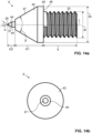
- a region of the distal end 26 of the ejector element 6 can comprise a first conical element 43 followed by a second element 44 terminating in an acute tip 27, i.e. in a tip 27 that defines an acute angle ⁇ .
- a proximal end 45 of the first conical element 43 is in connection with the outer thread 23 via which the ejector element 6 can be removably fastened to the inner thread 24 of the rod 5.
- Said proximal end 45 of the first conical element 43 furthermore comprises an undercut 46 having a diameter du that matches a diameter of the rod.
- outer surfaces 47 of the first conical element 43 run inwardly towards the longitudinal axis L run at an angle of 60° with respect to one another.
- the outer surfaces of the second element run inwardly towards the longitudinal axis and run at an angle ⁇ of 60° with respect to one another.
- a length Ic1 of the first conical element is 4 mm.
- a length Ic2 of the second element 44 is 1.5 mm and a diameter of the second element is 1 mm.
- a diameter du of the undercut is 7 mm
- a diameter dt of the outer thread is 5 mm
- a length It of the outer thread is 6.5 mm, respectively.
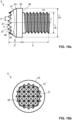
- the region of the distal end 26 of the ejector element 6 according to figures 15a and 15b comprises a conical element 43 that terminates in a plurality of acute tips 27. Said tips 27 are arranged next to one another and provide a serrated distal end face of the ejector element 6.
- the proximal end 45 of the conical element 43 is in connection with the outer thread 23 via which the ejector element 6 can be removably fastened to the inner thread 24 of the rod 5.
- said proximal end 45 of the conical element furthermore comprises an undercut 46 having a diameter du that matches a diameter of the rod.
- the outer surfaces 47 of the conical element run inwardly towards the longitudinal axis L and at an angle ⁇ of 60° with respect to one another.
- the outer surfaces 48 of each tip 27 run inwardly towards the longitudinal axis L and at an acute angle ⁇ , here at an angle ⁇ of 60° with respect to one another.
- a length Ic of the conical element 43 is here about 3.5 mm and a lateral distance d between neighbouring tips 27 is 1 mm.
- a diameter du of the undercut is 7 mm
- a diameter dt of the outer thread is 5 mm
- a length lt of the outer thread 23 is about 6.5 mm.
- Figures 16a and 16b depict another conceivable example of a region of the distal end 26 of the ejector element 6, which corresponds here to an essentially conical element 43 terminating in notches or grooves 49.
- the surfaces 48 defining the notch or groove 49 define an acute angle ⁇ with respect to one another, which is in the present case 90°.
- said surfaces 48 defining the notch or groove 49 run from the longitudinal axis L toward the distal end 26 of the tips 27 outwardly.
- the proximal end 45 of the conical element 43 is in connection with the outer thread 23 via which the ejector element 6 can be removably fastened to the inner thread 24 of the rod 5.
- said proximal end 45 of the conical element furthermore comprises an undercut 46 having a diameter du that matches a diameter of the rod.
- a length Ic of the conical element 43 is here about 4 mm
- a diameter du of the undercut is 7 mm
- a diameter dt of the outer thread is 5 mm
- a length It of the outer thread 23 is about 6.5 mm.
Landscapes
- Cleaning Implements For Floors, Carpets, Furniture, Walls, And The Like (AREA)
Description
- The present invention relates to a cleaning device according to
claim 1 and to a method of manufacturing a cleaning device according toclaim 14. - Cleaning devices such as mops, brooms, brushes or the like are well-known in the art. In places such as bathrooms or kitchens it is furthermore often desired to apply moisture or even detergents for better removal of pollutants to the cleaning device. To this end cleaning pads can be attached to certain cleaning devices, and wherein the moisture or detergent is applied to the surface or object to be cleaned via the cleaning pads. After cleaning the soiled cleaning pad is disposed and replaced by a new cleaning pad.
- So that a user does not has to grasp a soiled cleaning pad
US 2019/0387948 A1 discloses a cleaning tool comprising a handle to be gripped by a user and a body that is attached to the handle and to which a web is removably attachable. The body furthermore comprises a pushing unit that enables the user to remove the soiled web. The disadvantages associated with such a cleaning tool are the fact that a user must bend down to the body in order to actuate the pushing unit. Thereby the user comes into proximity with the soiled web which can be unpleasant and above all unhygienically for the user. - From
US 2019/387948 A1 a cleaning tool is known that comprises a handle configured to be grippable by a user, a body having one side to which the handle is pivotably connected and the other side providing an attachment surface to and from which a web for cleaning is attachable and detachable. The cleaning tool furthermore comprises a pushing unit provided at the handle to be movable therealong, wherein when the web is attached to the attachment surface, the pushing unit is movable along the handle to separate the web from the attachment surface. - From
EP 0 568 150 A1 a device for manually cleaning surfaces is known, that is formed by a tubular body with an elbow-like bent end bearing a support flange of a elastically deformable material and provided with an opening, onto which a paper sheet can be applied for performing the cleaning operation. After being used, the sheet is expelled by actuating a flexible organ housed and axially movable inside the tubular body and provided at its other end with an enlarged portion. - From
EP 3 251 575 A1 - It is an object of the present invention to overcome the disadvantages of the prior art. It is in particular an object of the present invention to provide a cleaning device that enables an ergonomic and hygienic handling.
- This object is achieved with a cleaning device according to
claim 1. In particular, a cleaning device is provided, which cleaning device comprises a handle extending along a longitudinal axis and a cleaning head. The cleaning head is in connection with the handle. Preferably, the cleaning head is pivotally in connection with the handle. The cleaning head is configured such that a cleaning pad is detachably fastenable to the cleaning head. The cleaning device further comprises a detaching device, wherein the detaching device is movably mounted to the handle and is configured to be moved along the longitudinal axis with respect to the handle from a cleaning position into a detaching position. In the cleaning position a cleaning pad being fastened to the cleaning head remains fastened to the cleaning head. In the detaching position a cleaning pad being fastened to the cleaning head is detached from the cleaning head. - To this end an ejection direction and a retraction direction can be defined. Both directions, i.e. the ejection direction and the retraction direction run parallel to the longitudinal axis.
- However, the ejection direction and the retraction direction run opposite to one another. In fact, the ejection direction is understood herein as a direction extending from a proximal end of the handle towards a distal end of the handle. Consequently, the retraction direction is understood as a direction extending from the distal end of the handle towards the proximal end of the handle. The detaching device is preferably movable along the ejection direction as well as along the retraction direction. In fact, it is preferred that the detaching device is movable along the ejection direction in the event that the detaching device is transferred from the cleaning position into the detaching position, and that the detaching device is movable along the retraction direction in the event that the detaching device is transferred from the detaching position into the cleaning position. That is, the detaching device is preferably configured to be moved along the longitudinal axis with respect to the handle from the cleaning position into the detaching position as well as from the detaching position into the cleaning position. It should be noted that statements made herein regarding a movement with respect to the longitudinal axis or along the longitudinal axis preferably correspond to a movement with respect to or along the ejection direction as well as the retraction direction.
- Hence, the cleaning device according to the invention comprises a detaching device that is mounted to the handle, wherein an actuation of the detaching device can be carried out in the region of the handle. Consequently, if a user wishes to replace a soiled cleaning pad he or she can simply actuate the detaching device while remaining in his or her position. In other words, the user does not have to bend himself down towards the cleaning pad. The cleaning device therefore enables an ergonomic and at the same time also hygienic handling.
- The handle preferably corresponds to an elongate bar which is grippable by a user. Moreover, the movement of the detaching device along the longitudinal axis of the handle preferably corresponds to an axial displacement of the detaching device with respect to the handle.
- The detaching device preferably comprises a rod extending along the longitudinal axis, wherein an ejector element is provided in the region of a distal end of the rod, and wherein the ejector element is configured to press against a cleaning pad being fastened to the cleaning head in order to detach the cleaning pad from the cleaning head when the detaching device is in the detaching position.
- That is, if the user wishes to replace the soiled cleaning pad he can transfer the detaching device from its cleaning position into its detaching position by moving the detaching device along the longitudinal axis, in particular along the ejection direction, whereby the ejector element is moved relative to the handle and towards the cleaning pad until it presses against the cleaning pad and thereby pushes the cleaning pad away from the cleaning head. In the detaching position the ejector element preferably at least partially protrudes from the cleaning head when seen along the ejection direction, i.e. the ejector element preferably at least partially protrudes from an underside of the cleaning device and towards a floor when seen in a state of use. In order to attach a new cleaning pad to the cleaning device the user preferably transfers the detaching device from its detaching position into its cleaning position by moving the detaching device along the longitudinal axis, in particular along the retraction direction, whereby the ejector element is moved relative to the handle from its protruding position back into a non-protruding position, i.e. into the cleaning position.
- The ejector element and the rod can be provided as a single piece element. Alternatively, it is likewise conceivable that the ejector element and the rod are configured separately from one another. In the latter case it is furthermore conceivable to removably or permanently fasten the ejector element to the rod. If the ejector element is configured removably it can be replaced by a new ejector element, for example if an ejector element is broken. The rod and the ejector element are preferably mounted at least partially in the handle. In fact, the rod and the ejector element are preferably arranged entirely within the handle when the detaching device is in its cleaning position. Hence, it is preferred that the handle is essentially hollow and preferably corresponds to a hollow bar.
- The ejector element can have various shapes. For example, the ejector element can have an uneven shape. An uneven shape could be provided by means of a serration, jags, spikes, indents, etc. that are preferably provided at a distal end of the ejector element. Additionally or alternatively the ejector element can have one or more surfaces which run at angle with respect to the longitudinal axis and/or with respect to a transverse axis running perpendicularly to the longitudinal axis. In this regard it is preferred that a distal end of the ejector element defines an angle that is acute and/or which is 90° or less, preferably 80° or less such as 60° with respect to the longitudinal axis. Additionally or alternatively the ejector element can be configured as one or more tips such as one or more conical tips or can correspond to one or more needles or can correspond to one or more clamps or is serrated, etc. One or more of these elements are preferably provided in a distal region or at the distal end of the ejector element such that they can act on the cleaning pad when the detaching device is in the detaching position. These one or more elements serve the purpose of facilitating a uniform detachment of the cleaning pad from the cleaning head.
- The rod can be movably mounted in the handle and can be movable along the longitudinal axis with respect to the handle from the cleaning position into the detaching position and/or from the detaching position into the cleaning position.
- That is, the rod of the detachment device can be movably mounted in the handle such that the rod is moved along the longitudinal axis, in particular along the ejection direction, when the cleaning device is transferred from the cleaning position into the detaching position. Additionally or alternatively the rod of the detachment device can be movably mounted in the handle such that the rod is moved along the longitudinal axis, in particular along the retraction direction, when the cleaning device is transferred from the detaching position into the cleaning position.
- The ejector element can be configured to be moved together with the rod with respect to the longitudinal axis. In other words, the detaching device can be configured such that the rod and the ejector element are concurrently and/or jointly moved with respect to the handle. In this case, if a user transfers the detaching device from the cleaning position into the detaching position (or vice versa) he can simply move the detaching device with respect to the longitudinal axis, wherein the rod and the ejector element are concurrently and/or jointly moved during the same movement.
- Alternatively, the ejector element can be configured to be moved separately from the rod with respect to the longitudinal axis. That is, it is likewise conceivable that the rod and the ejector element are moved successively or in a staggered manner and/or distinct from one another with respect to the handle. In this case, if a user transfers the detaching device from the cleaning position into the detaching position (or vice versa) a movement of either the rod or of the ejector element is performed before and/or separated from the movement of the other component. In this regard it is particularly preferred if the rod is moved with respect to the ejection direction before the ejector element is moved with respect to the ejection direction. It is thus also particularly preferred if the ejector element is moved with respect to the retraction direction before the rod is moved with respect to the retraction direction. In this latter case it is preferred if the ejector element is movable mounted with respect to the rod. For example, the ejector element could be mounted at least partially within the rod.
- The detaching device can further comprise a tube extending along the longitudinal axis, wherein the tube is mounted in the handle, and wherein the rod and preferably also the ejector element are at least partially mounted in the tube and are configured to be moved along the longitudinal axis with respect to the tube. This tube can be seen as a sleeve or the like within which the rod and possibly also the ejector element are arranged. The provision of such a tube or sleeve is particularly preferred in the event that the ejector element is configured to be moved separately from the rod with respect to the longitudinal axis mentioned above. The tube or sleeve is preferably arranged in the handle in a nondisplaceable i.e. fixed manner. Hence, the tube or sleeve can be seen as a guiding element which guides a movement of the rod and preferably also of the ejector element along the longitudinal axis. The rod preferably extends from a distal end of the tube at least partially towards a proximal end of the tube.
- The cleaning device further comprises at least one actuation device, wherein the actuation device is operatively connected to the detaching device and is configured to transfer the detaching device from the cleaning position into the detaching position and/or from the detaching position into the cleaning position upon actuation. That is, the detaching device is preferably transferred from its cleaning position into its detaching position and vice versa via the actuation device.
- The actuation device is preferably mounted on the handle. Furthermore, the actuation device can be configured to be moved along the longitudinal axis with respect to the handle, whereby a movement of the actuation device results in a movement of the detaching device. The actuation device preferably corresponds to a sleeve which is movably mounted on the handle, in particular on an outer surface of the handle. In addition, it is conceivable that the sleeve extends only partially or entirely around a circumference of the handle. An actuation of the movable actuation device is preferably achieved by grasping the actuation device and moving it along the handle with respect to the longitudinal axis. During this motion the detaching device is moved, as well. The sleeve can correspond to a single-piece or a multipiece element. Additionally or alternatively, the actuation device can be configured to be pivoted with respect to the handle, whereby a pivoting of the actuation device results in a movement of the detaching device. In this case it is preferred that the actuation device corresponds to a lever which can be pivoted by a user. The actuation device is preferably arranged on an outer surface of the handle. The pivotable actuation device preferably pivots about a pivoting axis running perpendicularly to the longitudinal axis. An actuation of the pivotable actuation device is preferably achieved by grasping the actuation device and pivoting it about the pivoting axis, wherein said pivotal motion of the actuation device is transferred into a movement of the detaching device with respect to the longitudinal axis via a lever joint or the like. Additionally or alternatively the actuation device can be configured to be rotated about a rotation axis extending parallel to the longitudinal axis. The advantages of a rotational actuation device are explained further below with respect to the one or more handle guiding elements.
- The detaching device further comprises at least one mounting element, wherein the mounting element is arranged in the handle and is in connection with the actuation device. An operative connection between the actuation element and the detaching device is preferably accomplished via the mounting element. Furthermore, the detaching device is preferably mounted to the handle via the mounting element. A cross-section of the mounting element preferably essentially corresponds to a cross-section of the handle. By providing a mounting element with a cross-section that essentially corresponds to a cross-section of the handle a tilting of the mounting element with respect to the handle can be prevented. The rod of the detaching device is preferably connected to the mounting element. Consequently, a tilting of the rod is prevented as well. It is preferred that the cross-sections of the mounting element and of the handle are such, that the mounting element is arranged in the handle in a movable but essentially play-free manner. In other words, it is preferred that the cross-section of the mounting element is slightly smaller than the cross-section of the handle. A conceivable cross-section of the handle is in the range of about 15 millimeter to 50 millimeter, more preferably in the range of about 18 millimeter to 25 millimeter. A conceivable cross-section of the mounting element is in the range of about 14 millimeter to 49 millimeter, more preferably in the range of about 17 millimeter to 24 millimeter.
- A length of the detaching device, in particular a length of the rod and a length of the ejector element, is preferably at least 50 %, more preferably at least 75 % of a length of the handle with respect to the longitudinal axis.
- That is to say, a length of the detaching device is preferably at least half of a length of the handle, more preferably at least a three-quarter of a length of the handle. For example, if a length of the handle with respect to the longitudinal axis is 1 meter it is preferred that a length of the detaching device is at least 0.5 meter, more preferably at least 0.75 meter. A length of the handle is preferably between 1 meter and 1.5 meter.
- The detaching device preferably extends from the distal end of the handle at least partially towards the proximal end of the handle.
- The actuation device is preferably arranged in a proximal region of the detaching device, i.e. on a side of the cleaning device facing the user. Consequently, the actuation device is arranged in an upper region of the handle and can be actuated easily by a user.
- The handle preferably comprises at least one handle guiding element and the detaching device comprises at least one detaching guiding element, and wherein the handle guiding element and the detaching guiding element provide a guidance for the detaching device with respect to a movement of the detaching device along the longitudinal axis.
- The at least one handle guiding element preferably corresponds to a slot in the handle that extends at least partially along the longitudinal axis. The handle can comprise one or more handle guiding elements. The at least one detaching guiding element preferably corresponds to a protrusion such as a bolt, pin, screw or the like protruding from the detaching device preferably radially outward and which protrusion is received in the slot of the handle in a slidably manner. The detaching device can comprise one or more detaching guiding elements. Hence if the detaching device is moved along the longitudinal axis the protrusion will slide within as well as along the slot, and wherein a rotation of the detaching device with respect to the handle is prevented. Hence, the handle guiding element and the detaching guiding element provide axial guidance. The actuation device mentioned above is particularly preferably mounted to the one or more handle guiding elements of the handle.
- The detaching device, in particular the rod and/or the mounting element, can be in connection with the actuation device via the detaching guiding element.
- The detaching guiding element preferably corresponds to a bolt, pin, screw or the like that extends from the actuation device through the handle guiding element at least partially into the detaching device, in particular the rod and/or the mounting element. For example, it is conceivable to screw the actuation device to the handle, and wherein said screw extends through the handle guiding element in the form of the slot in the handle into an interior of the handle and further through the mounting element and the rod arranged within the handle. The screw that is used for screwing can be understood as a detaching guiding element.
- The cleaning device preferably further comprises at least one locking device, wherein the locking device is configured to adapt at least a locking position and an unlocking position, wherein the locking device in the locking position is configured to lock the detaching device in the cleaning position and to enable a transfer of the detaching device from the cleaning position into the detaching position in the unlocking position.
- To this end various embodiments of a locking device are conceivable. In fact, the locking device can be configured such, that the locking device is transferable from its locking position into its unlocking position and/or from its unlocking position into its locking position upon a rotation of the locking device, preferably via a rotation of the actuation device, around a rotation axis extending parallel to the longitudinal axis. For example, according to this first aspect the locking device could comprise a recess extending in the handle and along an axis running at an angle and preferably perpendicularly to the longitudinal axis and a projection being provided on the rod or the mounting element, for example. By rotating the detaching device, the projection on the rod or on the mounting element is rotated into the recess or out of the recess. When the projection is in the recess it abuts against the recess if a user exerts a force on the locking device extending along the longitudinal axis, in particular along the ejection direction, whereby a movement of the detaching device along the longitudinal axis is prevented. If the cleaning device comprises an actuation device it is preferred that said rotation of the detaching device is achieved via a rotation of the actuation device. Hence, the actuation device is preferably not only movably mounted on the handle but also rotatably mounted on the handle and configured to rotate about a rotation axis extending parallel to the longitudinal axis. In this context it is particularly preferred that the recess of the locking device leads into the slot in the handle mentioned above. In this case, in order to detach a cleaning pad from the cleaning head, a user could rotate the actuation device about the rotation axis in a first step so as to remove the protrusion of the locking device, here the detaching guiding element, from the recess formed in the handle, and could then move the actuation device along the ejection direction so as to eject the cleaning pad in a second step. Upon ejection of the cleaning pad, the detaching device could be brought back into its cleaning position by moving the actuation device along the retraction direction in a first step and by rotating the actuation device about the rotation axis in a second step, whereby the protrusion or detaching guiding element, respectively, is rotated into the recess in the handle. Additionally or alternatively the locking device can comprise a recess and a projection, and wherein the projection is receivable in the recess so as to form a stop preventing a movement of the detaching device along the longitudinal axis in the locking position. For example, according to this second aspect it is conceivable that the locking device comprises an inner thread and outer thread, wherein the inner thread could be arranged on the handle or on the actuation device and the outer thread could be arranged on the detaching device such as on the rod or on the mounting element. In order to eject the cleaning pad from the cleaning head a user would have to release the threaded connection established between the inner and outer threads in a first step, which is achieved by rotating the handle or the actuation device with respect to the rod or the mounting element about the rotation axis. Hence, also in this case it is preferred that the actuation device is designed to be rotatable about a rotation axis extending parallel to the longitudinal axis. Additionally or alternatively the locking device can comprise an inner thread and a corresponding outer thread, which threads are configured to enter a threaded connection with one another, and wherein the locking device is in its locking position when the threads are in the threaded connection. For example, according to this third aspect the locking device can comprise two or more engagement elements that are configured to engage one another and at least one release element that is configured to release the engagement between the engagement elements. When the engagement elements are in the engaged state, the locking device is in its locking position. When the engagement between the engagement elements is released, the locking device is in its unlocking position. A first engagement element could be provided by means of a recess in the detaching device, for example in the rod, or in the mounting element. A second engagement element being configured to engage with the first engagement element could be provided by an element being receivable in the recess such as a bolt, pin or the like. The release element could be provided in the form of a button or bar or the like which can be pushed or shifted by a user so as to move the bolt, pin or the like out of the recess. The release element is preferably pretensioned and could be arranged on the handle or the actuation device, for example. Additionally or alternatively the locking device can be configured such, that it exerts a retaining force on the detaching device, preferably on the rod and/or the ejector element, in the absence of a force being applied on the detaching device by a user and being greater than the retaining force. For example, according to this fourth aspect the locking device can correspond to a retaining element exerting a retaining force on the detaching device, whereby the detaching device is prevented from moving along the longitudinal axis, in particular along the ejection direction. In order to detach the cleaning pad from the cleaning head a force being greater than the retaining force has to be applied to the detaching device. For example, the retaining element could correspond to a projection such as a lug that protrudes into the handle and provides an abutment for the detaching device, preferably for the rod and/or the ejector element. In the absence of a force exerted by a user said projection is capable of maintaining the detachment device in the cleaning position. In order to transfer the detaching device into its detaching position a user has to exert a force on the detaching device, e.g. by pushing the detaching device downwards, i.e. along the ejection direction. If said pushing force is larger than the retaining force exerted by the projection the detaching device is moved along the longitudinal axis, i.e. along the ejection direction. Additionally or alternatively the locking device can comprise a preferably preloaded retaining element acting on the detaching device, preferably on the rod and/or on the ejector element, so as to exert a retaining force on the detaching device, preferably on the rod and/or on the ejector element, the retaining element preferably corresponding to one or more projections extending into an interior of the handle. For example, according to this fifth aspect a pretensioned retaining element and/or an elastic element exerting a spring force or an elastic force can be provided which acts on the detaching device. Moreover, the retaining element could be arranged and configured so as to move outwardly along a radial direction extending perpendicularly to the longitudinal axis upon the application of force on the detaching device. In other words, the retaining element could spring back or flex back upon the application of force being greater than its retaining force, i.e. its spring force or elasticity. That is, various locking devices are conceivable in order to lock the detaching device in its cleaning position. To this end it should be noted that the cleaning device can comprise only one of the locking devices or two or more of the locking devices.
- The cleaning head can comprise at least one through opening extending through the cleaning head along the longitudinal axis, and wherein the detaching device, in particular the ejector element, extends at least partially through the through opening of the cleaning head when the detaching device is in the detaching position. Hence, it is preferred if the cleaning head comprises at least one through opening through which the detaching device, in particular at least part of the ejector element, can protrude in the event that the detaching device is transferred into its detaching position.
- The cleaning head is preferably mounted to the handle via a joint, particularly preferably via a biaxial or multi-axial joint. The biaxial joint preferably allows a pivoting of the handle about two axes. For example, the biaxial joint could be configured such that the handle can be pivoted with respect to the cleaning head along a first pivoting axis extending perpendicularly to the longitudinal axis as well as along a second pivoting axis extending perpendicularly to the longitudinal axis and the first pivoting axis. The first pivoting axis and the second pivoting axis preferably span a plane that is parallel to a plane extending through the cleaning head. The biaxial or multi-axial joint results in a large freedom of movement of the cleaning head. In fact, it enables a movement of the cleaning head with respect to the handle of 360°. Furthermore, the joint enables a permanent pivoting of the cleaning head. That is, the cleaning head can be pivoted with respect to the handle when the detaching device is in the cleaning position as well as in the detaching position.
- The cleaning head preferably is of a square or rectangular shape and thus preferably corresponds to a square or rectangular plate or the like. Furthermore, the cleaning head can comprise an upper surface facing the handle and a lower surface facing a floor. The joint is preferably arranged on the upper surface of the cleaning head and the lower surface of the cleaning head is preferably configured to allow an attachment of the cleaning pad.
- The joint preferably comprises at least one through opening extending through the joint along the longitudinal axis. Hence, it is also preferred if the joint comprises at least one through opening through which the detaching device, in particular at least part of the ejector element, can protrude in the event that the detaching device is transferred into its detaching position. That is, at least part of the detaching device, in particular at least part of the ejector element and probably also of the handle, extends through the through opening of the joint and the through opening of the cleaning head when the detaching device is transferred into its detaching position. To this end it is thus preferred when the through opening of the joint and the through opening of the cleaning head are arranged above one another with respect to the longitudinal axis. Moreover, the through opening of the joint and the through opening of the cleaning head are preferably arranged centrally with respect to the joint and the cleaning head, respectively. Thus, it is preferred to centrally arrange the joint on the cleaning head.
- The joint, in particular its distal end, can be attached to the cleaning head according to well-known manners, e.g. by screwing it to the cleaning head or by means of a snap connection, a click connection, etc.. A connection between the joint and the handle can be achieved in various ways as well. For example, the joint, in particular its proximal end, can be attached to the distal end of the handle. For instance, the proximal end of the joint could be inserted into the distal end of the handle, wherein an attachment between the joint and the handle is achieved by a friction fit. However, other or additional fastening means such as gluing the joint to the handle are likewise conceivable. In the event that the joint is at least partially received in the handle as just explained it is preferred that one or more retaining elements as described above are provided on the joint, in particular in the region of the through opening of the joint. Hence, it is preferred that the joint comprises a locking device being configured to lock the detaching device in its cleaning position.
- The cleaning device is preferably configured for cleaning a floor or the like. That is, the cleaning device is preferably a floor cleaning device.
- The cleaning pad is preferably a textile pad or a textile cloth, particularly preferably a disposable textile pad or a disposable textile cloth. To this end various types of pads or clothes are conceivable: For example, the pad or cloth can correspond to a single layer or a multi-layer component. They can be made of nonwoven, or knitted, or sewn fabrics made from natural and/or synthetic fibres. However, any other cleaning pad known in the art is conceivable as well.
- In a further aspect a cleaning pad is provided, which cleaning pad is configured to be detachably fastened to a cleaning device as described above.
- A detachable fastening of the cleaning pad to the cleaning head can be achieved according to known methods as well. For example, the cleaning pad can be attached to the cleaning head via a Velcro fastener, one or more clips or clamps, etc.
- In a further aspect a method of manufacturing a cleaning device, preferably a cleaning device as described above, is provided. The method comprises the steps of i) providing a handle extending along a longitudinal axis, and ii) providing a cleaning head. The cleaning head is preferably pivotally in connection with the handle. The cleaning head is configured such that a cleaning pad is detachably fastenable to the cleaning head. The method further comprises the step of iii) providing a detaching device, wherein the detaching device is movably mounted to the handle and is configured to be moved along the longitudinal axis with respect to the handle from a cleaning position, in which a cleaning pad being fastened to the cleaning head remains fastened to the cleaning head, into a detaching position, in which a cleaning pad being fastened to the cleaning head is detached from the cleaning head.
- It should be noted that steps i) to iii) can be carried out in any order as well as in a consecutive or simultaneous manner.
- Preferred embodiments of the invention are described in the following with reference to the drawings, which are for the purpose of illustrating the present preferred embodiments of the invention and not for the purpose of limiting the same. In the drawings,
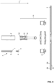
- Fig. 1
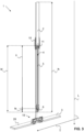
- shows a perspective view of a cleaning device comprising a handle, a cleaning head, and a detaching device in a cleaning position;
- Fig. 2
- shows an exploded view of the cleaning device according to
figure 1 ; - Fig. 3
- shows a sectional view of the cleaning device according to
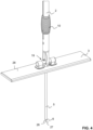
figure 1 ; - Fig. 4
- shows a partial perspective view of the cleaning device according to
figure 1 in a detaching position; - Fig. 5
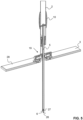
- shows a sectional view of the cleaning device according to
figure 4 ; - Fig. 6
- shows a perspective view of the cleaning device depicted in area A according to
figure 1 ; - Fig. 7
- shows an exploded view of the cleaning device depicted in area A according to
figure 1 ; - Fig. 8
- shows a an exploded sectional view of the cleaning device depicted in area A according to
figure 1 ; - Fig. 9
- shows a partial perspective view of the cleaning depicted in area A according to
figure 1 ; - Fig. 10
- shows a partial sectional view of the cleaning device depicted in area A according to
figure 1 ; - Fig. 11
- shows another partial sectional view of the cleaning device depicted in area A according to
figure 1 ; - Fig. 12
- shows an enlarged view of area C in
figure 11 ; - Fig. 13a
- shows a sectional view of the cleaning device depicted in area B according to
figure 1 ; - Fig. 13b
- shows another sectional view of the cleaning device depicted in area B according to
figure 1 ; - Fig. 14a
- shows a side view of an ejector element of the detaching device according to another embodiment;
- Fig. 14b
- shows a front view of the ejector element according to
figure 14a ; - Fig. 15a
- shows a side view of an ejector element of the detaching device according to another embodiment;
- Fig. 15b
- shows a front view of the ejector element according to
figure 15a ; - Fig. 16a
- shows a side view of an ejector element of the detaching device according to another embodiment;
- Fig. 16b
- shows a front view of the ejector element according to
figure 16a . - Several aspects of a
cleaning device 1 according to the invention are now discussed with reference tofigures 1 to 13b . Thecleaning device 1 is configured for cleaning a floor or the like and can be referred to as a floor cleaning device. Thecleaning device 1 comprises ahandle 2 in the form of an elongate hollow bar extending along a longitudinal axis L. Thehandle 2 comprises aproximal end 21 and an opposeddistal end 22. A cleaninghead 3 is pivotally connected to thehandle 2 at the distal end of thehandle 2. The cleaninghead 3 comprises fastening means such as Velcro fastening or the like (not depicted) that allow a releasable connection with corresponding fastening means on a cleaning pad (not depicted). Hence, the cleaninghead 3 is configured such that a cleaning pad is detachably fastenable to thecleaning head 3. The cleaning pad is preferably a textile pad or a textile cloth. - The
cleaning device 1 further comprises adetaching device 4 that is movably mounted to thehandle 2 and is configured to be moved along the longitudinal axis L with respect to thehandle 2 from a cleaning position, in which a cleaning pad being fastened to thecleaning head 3 remains fastened to thecleaning head 3, into a detaching position, in which a cleaning pad being fastened to thecleaning head 3 is detached from the cleaninghead 3. - To this end an ejection direction E and a retraction direction R are defined. The ejection direction E extends from the
proximal end 21 of thehandle 2 towards thedistal end 22 of thehandle 2. The retraction direction R extends from thedistal end 22 of thehandle 2 towards theproximal end 21 of thehandle 2.Figures 1 to 3 depict thecleaning device 1 in its cleaning position andfigures 4 to 5 depict thecleaning device 1 in its detaching position. - As best seen in
figure 2 thedetaching device 4 comprises arod 5 extending along the longitudinal axis L and comprising aproximal end 8 and adistal end 7. The detachingdevice 4 furthermore comprises anejector element 6 which is provided in a region of thedistal end 7 of therod 5. Here, theejector element 6 and therod 5 are provided as separate components, wherein theejector element 6 is removably fastenable to therod 5 via correspondingfastening elements figure 12 , for example, the fastening elements can be provided by means of anouter thread 23 being arranged in a region of theproximal end 25 of theejector element 6 and aninner thread 24 being arranged in region of thedistal end 7 of therod 5. Hence, theejector element 6 and therod 5 can be connected to one another via a threaded connection. - The
rod 5 is movably mounted in thehandle 2 and is movable along the longitudinal axis L with respect to thehandle 2 from the cleaning position into the detaching position and from the detaching position into the cleaning position. In the present example theejector element 6 is firmly connected to therod 5 via the threadedconnection rod 5 with respect to thehandle 2 and along the longitudinal axis L. - The
ejector element 6 is configured to press against a cleaning pad being fastened to thecleaning head 3 in order to detach the cleaning pad from the cleaninghead 3 when thedetaching device 4 is in the detaching position. To this end theejector element 6, in particular a region of itsdistal end 26, has an uneven shape comprisingseveral surfaces 9 which run at angle with respect to the longitudinal axis L as well as with respect to a transverse axis T running perpendicularly to the longitudinal axis L so as to form aconical tip 27. In fact, when thedetaching device 4 is transferred from its cleaning position as depicted infigures 1 to 3 into its detaching position as depicted infigures 4 to 5 , theconical tip 27 of theejector element 6 will press against the cleaning pad and push the cleaning pad away from the cleaninghead 3. Due to its shape theejector element 6 results in a uniform detachment of the cleaning pad from the cleaninghead 3. Various designs of theejector element 6 are conceivable, examples of which will be discussed in greater detail with respect tofigures 14a to 16b . - As best seen in
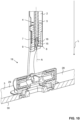
figures 7 to 11 thecleaning head 3 comprises arectangular plate 28 having anupper surface 29 facing thehandle 2 and alower surface 30 facing a floor in an application state of thecleaning device 1. A joint 19 is preferably arranged on theupper surface 29 of thecleaning head 3 and thelower surface 30 of thecleaning head 3 is preferably configured to allow an attachment of the cleaning pad. The cleaninghead 3 is mounted to thehandle 2 via the joint 19. The joint 19 corresponds here to a biaxial joint which allows a pivoting of thehandle 2 about two axes. In particular, the biaxial joint 19 is configured such that thehandle 2 can be pivoted with respect to thecleaning head 3 along a first pivoting axis P1 extending perpendicularly to the longitudinal axis L as well as along a second pivoting axis P2 extending perpendicularly to the longitudinal axis L and the first pivoting axis P1. The first pivoting axis P1 and the second pivoting axis P2 preferably span a plane that is parallel to a plane spanning therectangular plate 28 of thecleaning head 3. - The cleaning
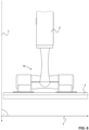
head 3 comprises a throughopening 18 extending through the cleaninghead 3 along the longitudinal axis L, and wherein thedetaching device 4, in particular theejector element 6, extends at least partially through the through opening 18 of thecleaning head 3 when thedetaching device 4 is in the detaching position. In order to allow a movement of thedetaching device 4 through the cleaninghead 3 also the joint 19 comprises a throughopening 20 extending along the longitudinal axis L. To this end the through opening 20 of the joint 19 and the through opening 18 of thecleaning head 3 are arranged above one another with respect to the longitudinal axis L. In other words, a (fictitious) line extending through the through opening 20 of the joint 19 coincides with a (fictitious) line extending through the through opening 18 of thecleaning head 3. Moreover, the through opening 20 of the joint 19 and the through opening 18 of thecleaning head 3 are arranged centrally with respect to the joint 19 and thecleaning head 3, respectively. Adistal end 31 of the joint 19 is attached to thecleaning head 3 via a snap-connection, wherein here twoprotrusions 33 of the joint 19 are snapped into correspondingrecesses 34 provided in thecleaning head 3. A connection between the joint 19 and thehandle 2 is achieved here via aproximal end 32 of the joint 19 that is attached to thedistal end 22 of thehandle 2. In particular, theproximal end 32 of the joint 19 is inserted into thedistal end 22 of thehandle 2, and wherein an attachment between the joint and thehandle 2 is achieved by a friction fit as well as a snap connection established between a protrudingnose 35 provided on the joint 19 and acorresponding recess 36 provided in thehandle 2. - In order to enable an unobstructed cleaning by the
cleaning device 1 the detaching device shall remain in its cleaning position during a cleaning operation. To this end thecleaning device 1 further comprises at least onelocking device 15, which is configured to adapt at least a locking position and an unlocking position. In the locking position the lockingdevice 15 is configured to lock thedetaching device 4 in the cleaning position, wherein theejector element 6 is mounted within thehandle 2. In the unlocking position the lockingdevice 15 allows a transfer of thedetaching device 4 from the cleaning position into the detaching position. As follows fromfigure 12 thelocking device 15 is configured such that it exerts a retaining force on thedetaching device 4, here on theejector element 6, in the absence of a force being applied on thedetaching device 4 by a user and being greater than the retaining force. In particular, the lockingdevice 15 comprises a preloaded retainingelement 16 in the form of an elastic and/or pretensioned lug which protrudes inwardly into an interior 17 of thehandle 2 and which provides anabutment surface 37 for theejector element 6. In the absence of a force exerted by a user saidlug 16 is capable of maintaining thedetachment device 4 in the cleaning position. In order to transfer thedetaching device 4 into its detaching position a user has to exert a force on thedetaching device 4, e.g. by pushing thedetaching device 4 downwards along the ejection direction E. If said pushing force is larger than the retaining force exerted by thelug 16 thelug 16 is pressed by theejector element 6 radially outward, i.e. it deflects along a radial direction O, and thedetaching device 4 can be moved along the longitudinal axis. As indicated infigure 12 the radial direction O runs perpendicularly to the longitudinal axis L. - In order to move the
detaching device 4 along thehandle 2 from the detaching position into the cleaning position and vice versa thecleaning device 1 further comprises anactuation device 10. Theactuation device 10 is operatively connected to thedetaching device 4 and is configured to transfer thedetaching device 4 from the cleaning position into the detaching position and/or from the detaching position into the cleaning position upon its actuation. As follows fromfigures 1 to 3 , for example, theactuation device 10 is mounted on thehandle 2, in particular on anouter surface 38 of thehandle 2, and has the form of a sleeve that surrounds an entire circumference of thehandle 2. To this end theactuation device 10 is movable along the longitudinal axis L as well as rotatable about a rotation axis A. The rotation axis A extends parallel to the longitudinal axis L. Because of its operational connection with the detaching device 4 a movement of theactuation device 10 along the longitudinal axis L is transferred into a movement of thedetaching device 4 along the longitudinal axis L. Likewise, a rotation of theactuation device 10 about the rotation axis A is transferred into a rotation of thedetaching device 4 about the rotation axis A. A user can actuate theactuation device 10 by grasping theactuation device 10 and moving it along thehandle 2 with respect to the longitudinal axis L and/or by rotating it about the rotation axis A. - As indicated in
figure 3 a length Id of thedetaching device 4, in particular a total length being comprised of a length Ir of therod 5 and a length le of theejector element 6, is at least 50 % of a length Ih of thehandle 2 with respect to the longitudinal axis L. Furthermore, theactuation device 10 is arranged in aproximal region 12 of thedetaching device 4, in particular in a region of theproximal end 8 of therod 5. Consequently, theactuation device 10 is arranged in an upper region of thehandle 2 and can be actuated easily by a user. - As best seen in
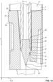
figures 13a and 13b , the detachingdevice 4 further comprises a mountingelement 11, which corresponds here to a block of an essentially cylindrical shape, and which is movably mounted within thehandle 2. The mountingelement 11 is in connection with theactuation device 10 such that a movement of theactuation device 10, e.g. a rotation about or a displacement along the longitudinal axis L is transferred onto the mountingelement 11. An external cross-section cm of the mountingelement 11 preferably essentially corresponds to an internal cross-section ch of thehandle 2. The internal cross-section ch can also be referred to as the clear width of thehandle 2. By providing a mountingelement 11 with a cross-section cm that essentially corresponds to a cross-sectionch of the handle 2 a tilting of the mountingelement 11 with respect to thehandle 2 can be prevented. Because therod 5 is connected to the mounting element 11 a tilting of therod 5 with respect to thehandle 2 is thereby prevented as well. - The mounting
element 11 comprises here two bores, afirst bore 39 extending along the longitudinal axis L and extending from adistal end 42 of the mountingelement 11 partially towards aproximal end 41 of the mountingelement 11, and asecond bore 40 extending perpendicularly to thefirst bore 39, i.e. along the transverse axis T. Therod 5 of thedetaching device 4 is mounted to the mountingelement 11 via itsfirst bore 39. More specifically, aregion 12 of theproximal end 8 of therod 5 is inserted into thefirst bore 39 and is connected to thefirst bore 39 by means of a press-fit and/or a form fit and/or a frictional fit. Thesecond bore 40 is used for connecting the mountingelement 11 with theactuation device 10. Said connection is achieved via ascrew 14 that extends from theactuation device 10 through thehandle 2, through therod 5 and essentially through thesecond bore 40 of the mountingelement 11. To this end thescrew 14 extends through aslot 13 running along the longitudinal axis L of thehandle 2, seefigures 1 and2 . Hence, if theactuation device 10 and thereby also thedetaching device 4 is moved along the longitudinal axis L thescrew 14 will slide within as well as along theslot 13, and wherein a rotation of thedetaching device 4 with respect to thehandle 2 is prevented. As a result an axial guidance is provided. Theslot 13 can thus also be referred to as ahandle 2 guidingelement 13 and thescrew 14 can be referred to as adetaching guiding element 14. - As mentioned earlier, various designs of the
ejector element 6 are conceivable. For instance, and as follows fromfigures 14a and 14b , a region of thedistal end 26 of theejector element 6 can comprise a firstconical element 43 followed by asecond element 44 terminating in anacute tip 27, i.e. in atip 27 that defines an acute angle α. Aproximal end 45 of the firstconical element 43 is in connection with theouter thread 23 via which theejector element 6 can be removably fastened to theinner thread 24 of therod 5. Saidproximal end 45 of the firstconical element 43 furthermore comprises an undercut 46 having a diameter du that matches a diameter of the rod. In the depicted example,outer surfaces 47 of the firstconical element 43 run inwardly towards the longitudinal axis L run at an angle of 60° with respect to one another. Also the outer surfaces of the second element run inwardly towards the longitudinal axis and run at an angle β of 60° with respect to one another. A length Ic1 of the first conical element is 4 mm. A length Ic2 of thesecond element 44 is 1.5 mm and a diameter of the second element is 1 mm. Furthermore, a diameter du of the undercut is 7 mm, a diameter dt of the outer thread is 5 mm, and a length It of the outer thread is 6.5 mm, respectively. -
Figures 15a and 15b as well asfigures 16a and 16b depict further conceivable examples of conceivable designs. In fact, the region of thedistal end 26 of theejector element 6 according tofigures 15a and 15b comprises aconical element 43 that terminates in a plurality ofacute tips 27. Saidtips 27 are arranged next to one another and provide a serrated distal end face of theejector element 6. Like in the embodiment offigures 14a and 14b , theproximal end 45 of theconical element 43 is in connection with theouter thread 23 via which theejector element 6 can be removably fastened to theinner thread 24 of therod 5. Also in this case saidproximal end 45 of the conical element furthermore comprises an undercut 46 having a diameter du that matches a diameter of the rod. Furthermore, theouter surfaces 47 of the conical element run inwardly towards the longitudinal axis L and at an angle β of 60° with respect to one another. Moreover, theouter surfaces 48 of eachtip 27 run inwardly towards the longitudinal axis L and at an acute angle α, here at an angle α of 60° with respect to one another. A length Ic of theconical element 43 is here about 3.5 mm and a lateral distance d betweenneighbouring tips 27 is 1 mm. Furthermore, a diameter du of the undercut is 7 mm, a diameter dt of the outer thread is 5 mm, and a length lt of theouter thread 23 is about 6.5 mm. -
Figures 16a and 16b depict another conceivable example of a region of thedistal end 26 of theejector element 6, which corresponds here to an essentiallyconical element 43 terminating in notches orgrooves 49. Like in the previous examples, thesurfaces 48 defining the notch or groove 49 define an acute angle α with respect to one another, which is in the present case 90°. In contrast to the previous examples, here saidsurfaces 48 defining the notch or groove 49 run from the longitudinal axis L toward thedistal end 26 of thetips 27 outwardly. Also in this case theproximal end 45 of theconical element 43 is in connection with theouter thread 23 via which theejector element 6 can be removably fastened to theinner thread 24 of therod 5. Likewise, saidproximal end 45 of the conical element furthermore comprises an undercut 46 having a diameter du that matches a diameter of the rod. Moreover, a length Ic of theconical element 43 is here about 4 mm, a diameter du of the undercut is 7 mm, a diameter dt of the outer thread is 5 mm, and a length It of theouter thread 23 is about 6.5 mm.LIST OF REFERENCE SIGNS 1 cleaning device 35 nose 2 handle 36 recess 3 cleaning head 37 abutment surface 4 detaching device 38 outer surface 5 rod 39 bore 6 ejector element 40 bore 7 distal end 41 proximal end 8 proximal end 42 distal end 9 surface 43 conical element 10 actuation device 44 conical element 11 mounting element 45 proximal end 12 proximal region 46 undercut 13 handle guiding element 47 outer surface 14 detaching guiding element 48 outer surface 15 locking device 49 groove or notch 16 retaining element 17 interior L longitudinal axis 18 through opening T transverse axis 19 joint A rotation axis 20 through opening O radial direction 21 proximal end E ejection direction 22 distal end R retraction direction 23 fastening element P1 pivoting axis 24 fastening element P2 pivoting axis 25 proximal end cm cross-section 26 distal end ch cross-section 27 tip lh length handle 28 plate le length ejector element 29 upper surface lr length rod 30 lower surface lc length conical element 31 distal end lc1 length conical element 32 proximal end lc2 length conical element 33 protrusion lt length thread 34 recess d distance α angle dt diameter β angle du diameter
Claims (14)
- A cleaning device (1) comprising:- a handle (2) extending along a longitudinal axis (L); and- a cleaning head (3),wherein the cleaning head (3) is preferably pivotally in connection with the handle (2), andwherein the cleaning head (3) is configured such that a cleaning pad is detachably fastenable to the cleaning head (3),wherein the cleaning device (1) further comprises a detaching device (4), wherein the detaching device (4) is movably mounted to the handle (2) and is configured to be moved along the longitudinal axis (L) with respect to the handle (2) from a cleaning position, in which a cleaning pad being fastened to the cleaning head (3) remains fastened to the cleaning head (3), into a detaching position, in which a cleaning pad being fastened to the cleaning head (3) is detached from the cleaning head (3), andwherein the cleaning device (1) further comprises at least one actuation device (10), wherein the actuation device (10) is operatively connected to the detaching device (4) and is configured to transfer the detaching device (4) from the cleaning position into the detaching position and/or from the detaching position into the cleaning position upon actuation, andcharacterized in that the detaching device (4) further comprises at least one mounting element (11), wherein the mounting element (11) is arranged in the handle (2) and is in connection with the actuation device (10).
- The cleaning device (1) according to claim 1, wherein the detaching device (4) comprises a rod (5) extending along the longitudinal axis (L), wherein an ejector element (6) is provided in the region of a distal end (7) of the rod (5), and wherein the ejector element (6) is configured to press against a cleaning pad being fastened to the cleaning head (3) in order to detach the cleaning pad from the cleaning head (3) when the detaching device (4) is in the detaching position.
- The cleaning device (1) according to claim 2, wherein at least one of i) the ejector element (6) has an uneven shape, ii) the ejector element (6) has one or more surfaces (9) which run at angle with respect to the longitudinal axis (L) and/or with respect to a transverse axis (T) running perpendicularly to the longitudinal axis (L), and iii) the ejector element (6) is configured as one or more tips, preferably one or more conical tips or corresponds to one or more needles or corresponds to one or more clamps or is serrated.
- The cleaning device (1) according to any one of claims 2 to 3, wherein the rod (5) is movably mounted in the handle (2) and is movable along the longitudinal axis (L) with respect to the handle (2) from the cleaning position into the detaching position and/or from the detaching position into the cleaning position, and/orwherein i) the ejector element (6) is configured to be moved together with the rod (5) with respect to the longitudinal axis (L), orwherein ii) the ejector element (6) is configured to be moved separately from the rod (5) with respect to the longitudinal axis (L).
- The cleaning device (1) according to any one of claims 2 to 4, wherein the detaching device (4) further comprises a tube extending along the longitudinal axis (L), wherein the tube is mounted in the handle (2), and wherein the rod (5) and preferably also the ejector element (6) are at least partially mounted in the tube and are configured to be moved along the longitudinal axis (L) with respect to the tube.
- The cleaning device (1) according to any one of the preceding claims, wherein the actuation device (10) is mounted on the handle (2), andwherein the actuation device (10) is configured to be moved along the longitudinal axis (L) with respect to the handle (2), whereby a movement of the actuation device (10) results in a movement of the detaching device (4), and/orwherein the actuation device (10) is configured to be pivoted with respect to the handle (2), whereby a pivoting of the actuation device (10) results in a movement of the detaching device (4), and/orwherein the actuation device (10) is configured to be rotated about a rotation axis (A) extending parallel to the longitudinal axis (L).
- The cleaning device (1) according to any one of the preceding claims, wherein a cross-section (cm) of the mounting element (11) essentially corresponds to a cross-section (ch) of the handle (2).
- The cleaning device (1) according to any one of the preceding claims, wherein a length (Id) of the detaching device (4), in particular a length (Ir) of the rod (5) and a length (le) the ejector element (6), is at least 50 %, preferably at least 75 % of a length (lh) of the handle (2) with respect to the longitudinal axis (L), and
wherein the actuation device (10) is preferably arranged in a proximal region (12) of the detaching device (4). - The cleaning device (1) according to any one of the preceding claims, wherein the handle (2) comprises at least one handle guiding element (13) and the detaching device (4) comprises at least one detaching guiding element (14), and wherein the handle guiding element (13) and the detaching guiding element (14) provide a guidance for the detaching device (4) with respect to a movement of the detaching device (4) along the longitudinal axis (L).
- The cleaning device (1) according to claim 9, wherein the detaching device (4), in particular the rod (5) and/or the mounting element (11), is in connection with the actuation device (10) via the detaching guiding element (14), and wherein the detaching guiding element (14) preferably corresponds to a bolt, pin, screw or the like that extends from the actuation device (10) through the handle guiding element at least partially into the detaching device (4), in particular the rod (5) and/or the mounting element (11).
- The cleaning device (1) according to any one of the preceding claims, further comprising at least one locking device (15), wherein the locking device (15) is configured to adapt at least a locking position and an unlocking position, wherein the locking device (15) in the locking position is configured to lock the detaching device (4) in the cleaning position and to enable a transfer of the detaching device (4) from the cleaning position into the detaching position in the unlocking position.
- The cleaning device (1) according to claim 11, wherein at least one of:i. the locking device is configured such, that the locking device is transferable from its locking position into its unlocking position and/or from its unlocking position into its locking position upon a rotation of the locking device, preferably via a rotation of the actuation device (10), around a rotation axis (A) extending parallel to the longitudinal axis (L);ii. the locking device comprises a recess and a projection, and wherein the projection is receivable in the recess so as to form a stop preventing a movement of the detaching device (4) along the longitudinal axis (L) in the locking position;iii. the locking device comprises an inner thread and a corresponding outer thread, which threads are configured to enter a threaded connection with one another, and wherein the locking device is in its locking position when the threads are in the threaded connection;iv. the locking device (15) is configured such, that it exerts a retaining force on the detaching device (4), preferably on the rod (5) and/or the ejector element (6), in the absence of a force being applied on the detaching device (4) by a user and being greater than the retaining force;v. the locking device (15) comprises a preferably preloaded retaining element (16) acting on the detaching device (4), preferably on the rod (5) and/or on the ejector element (6), so as to exert a retaining force on the detaching device (4), preferably on the rod (5) and/or on the ejector element (6), the retaining element (16) preferably corresponding to one or more projections extending into an interior (17) of the handle (2).
- The cleaning device (1) according to any one of the preceding claims, wherein the cleaning head (3) comprises at least one through opening (18) extending through the cleaning head (3) along the longitudinal axis (L), and wherein the detaching device (4), in particular the ejector element (6), extends at least partially through the through opening (18) of the cleaning head (3) when the detaching device (4) is in the detaching position, and/or
wherein the cleaning head (3) is mounted to the handle (2) via a joint (19), preferably via a biaxial or multi-axial joint, the joint (19) preferably comprising at least one through opening (20) extending through the joint (19) along the longitudinal axis (L). - A method of manufacturing a cleaning device (1), preferably a cleaning device according to any one of the preceding claims, the method comprising the steps of:- Providing a handle (2) extending along a longitudinal axis (L); and- Providing a cleaning head (3),wherein the cleaning head (3) is preferably pivotally in connection with the handle (2), andwherein the cleaning head (3) is configured such that a cleaning pad is detachably fastenable to the cleaning head (3),characterized in that the method further comprises the step of:- Providing a detaching device (4),wherein the detaching device (4) is movably mounted to the handle (2) and is configured to be moved along the longitudinal axis (L) with respect to the handle (2) from a cleaning position, in which a cleaning pad being fastened to the cleaning head (3) remains fastened to the cleaning head (3), into a detaching position, in which a cleaning pad being fastened to the cleaning head (3) is detached from the cleaning head (3),wherein the cleaning device (1) further comprises at least one actuation device (10), wherein the actuation device (10) is operatively connected to the detaching device (4) and is configured to transfer the detaching device (4) from the cleaning position into the detaching position and/or from the detaching position into the cleaning position upon actuation, andcharacterized in that the detaching device (4) further comprises at least one mounting element (11), wherein the mounting element (11) is arranged in the handle (2) and is in connection with the actuation device (10).
Applications Claiming Priority (2)
| Application Number | Priority Date | Filing Date | Title |
|---|---|---|---|
| EP20179247 | 2020-06-10 | ||
| PCT/EP2021/064922 WO2021249866A1 (en) | 2020-06-10 | 2021-06-03 | Cleaning device with detaching device |
Publications (3)
| Publication Number | Publication Date |
|---|---|
| EP4164464A1 EP4164464A1 (en) | 2023-04-19 |
| EP4164464B1 true EP4164464B1 (en) | 2025-04-16 |
| EP4164464C0 EP4164464C0 (en) | 2025-04-16 |
Family
ID=71083539
Family Applications (1)
| Application Number | Title | Priority Date | Filing Date |
|---|---|---|---|
| EP21730898.0A Active EP4164464B1 (en) | 2020-06-10 | 2021-06-03 | Cleaning device with detaching device |
Country Status (3)
| Country | Link |
|---|---|
| US (1) | US20230233048A1 (en) |
| EP (1) | EP4164464B1 (en) |
| WO (1) | WO2021249866A1 (en) |
Families Citing this family (1)
| Publication number | Priority date | Publication date | Assignee | Title |
|---|---|---|---|---|
| US12408808B2 (en) * | 2023-02-14 | 2025-09-09 | Carl Freudenberg Kg | Slide release mechanism for cleaning device |
Citations (8)
| Publication number | Priority date | Publication date | Assignee | Title |
|---|---|---|---|---|
| EP0568150A1 (en) | 1992-04-27 | 1993-11-03 | Albano Tosato | Surface cleaning device |
| US5722105A (en) | 1995-12-28 | 1998-03-03 | Thomasson; Stig Ola | Floor mop and wringing mechanism therefor |
| WO2001015587A1 (en) | 1999-09-01 | 2001-03-08 | Hagleitner Hygiene International Gmbh | Brush |
| WO2005034705A1 (en) | 2003-09-16 | 2005-04-21 | 3M Innovative Properties Company | Cleaning device with disposable pad |
| WO2017083374A1 (en) | 2015-11-13 | 2017-05-18 | 3M Innovative Properties Company | Cleaning tool having an easily detachable web |
| EP3251575A1 (en) | 2016-05-30 | 2017-12-06 | Leifheit Ag | Wiping system with a wiping device and a wipe container |
| US20180249880A1 (en) | 2017-03-01 | 2018-09-06 | Frankie Deniece Tidwell | Floor cleaning device and method |
| US20190387948A1 (en) | 2016-07-13 | 2019-12-26 | 3M Innovative Properties Company | Cleaning tool |
Family Cites Families (6)
| Publication number | Priority date | Publication date | Assignee | Title |
|---|---|---|---|---|
| GB0304446D0 (en) * | 2003-02-27 | 2003-04-02 | Loadstone Ltd | Cleaning device |
| US20070130713A1 (en) * | 2005-12-14 | 2007-06-14 | Kimberly-Clark Worldwide, Inc. | Cleaning wipe with textured surface |
| CN102655798A (en) * | 2009-10-06 | 2012-09-05 | 拉伯美德公司 | Cleaning apparatus with brush head disengager |
| US9655482B2 (en) * | 2013-03-05 | 2017-05-23 | Butler Home Products Llc | Cleaning scrubber for household surfaces |
| US11154176B2 (en) * | 2016-03-16 | 2021-10-26 | Medline Industries, Inc. | Mop with integrated head removal system |
| KR102101404B1 (en) * | 2018-09-04 | 2020-04-16 | 오세운 | Pad changeable mop |
-
2021
- 2021-06-03 US US18/009,249 patent/US20230233048A1/en active Pending
- 2021-06-03 EP EP21730898.0A patent/EP4164464B1/en active Active
- 2021-06-03 WO PCT/EP2021/064922 patent/WO2021249866A1/en not_active Ceased
Patent Citations (8)
| Publication number | Priority date | Publication date | Assignee | Title |
|---|---|---|---|---|
| EP0568150A1 (en) | 1992-04-27 | 1993-11-03 | Albano Tosato | Surface cleaning device |
| US5722105A (en) | 1995-12-28 | 1998-03-03 | Thomasson; Stig Ola | Floor mop and wringing mechanism therefor |
| WO2001015587A1 (en) | 1999-09-01 | 2001-03-08 | Hagleitner Hygiene International Gmbh | Brush |
| WO2005034705A1 (en) | 2003-09-16 | 2005-04-21 | 3M Innovative Properties Company | Cleaning device with disposable pad |
| WO2017083374A1 (en) | 2015-11-13 | 2017-05-18 | 3M Innovative Properties Company | Cleaning tool having an easily detachable web |
| EP3251575A1 (en) | 2016-05-30 | 2017-12-06 | Leifheit Ag | Wiping system with a wiping device and a wipe container |
| US20190387948A1 (en) | 2016-07-13 | 2019-12-26 | 3M Innovative Properties Company | Cleaning tool |
| US20180249880A1 (en) | 2017-03-01 | 2018-09-06 | Frankie Deniece Tidwell | Floor cleaning device and method |
Also Published As
| Publication number | Publication date |
|---|---|
| EP4164464A1 (en) | 2023-04-19 |
| EP4164464C0 (en) | 2025-04-16 |
| WO2021249866A1 (en) | 2021-12-16 |
| US20230233048A1 (en) | 2023-07-27 |
Similar Documents
| Publication | Publication Date | Title |
|---|---|---|
| EP2040886B1 (en) | Cleaning tool system comprising a quick-release handle | |
| CA1181910A (en) | Bowl mop | |
| US5803646A (en) | Apparatus for the detachable fastening of cleaning implements | |
| US8607400B2 (en) | Disposable liquid absorbing cleaning pad for a hand held cleaning implement having an elongated handle | |
| EP2046186A1 (en) | Mop assembly with reversible head | |
| US20090094791A1 (en) | Combination handle and extension handle kit for cleaning implements | |
| EP1399053A1 (en) | Cleaning implement comprising a gliding element | |
| GB2146890A (en) | Scrubber mop | |
| EP2053958A2 (en) | Adjustable-size mop head and selectable-size cleaning substrate | |
| EP4164464B1 (en) | Cleaning device with detaching device | |
| US20120180236A1 (en) | Mop | |
| CA2309441A1 (en) | Wringing method and wringing mechanism for floor mop | |
| WO2025075859A1 (en) | Mop assembly with sliding, rotatable and clamping wringer sleeve | |
| US20060130261A1 (en) | Quick release paint roller assembly | |
| CA2155290C (en) | Releasable mop head | |
| US20080313858A1 (en) | Detachable extension handle | |
| WO2006069266A2 (en) | Quick release paint roller assembly | |
| US8296895B2 (en) | Disposable liquid absorbing cleaning pad for a hand held cleaning implement having an elongated handle | |
| JP4347465B2 (en) | Angle adjustable cleaning tool | |
| CN217852813U (en) | Flat mop | |
| EP4039163B1 (en) | Multi-function cleaning tool | |
| JP4508989B2 (en) | Cleaning tool | |
| CN220860014U (en) | Cleaning head and cleaning tool | |
| US20250186168A1 (en) | Instrument head with lever mechanism for clamping a treatment tool | |
| JP7538669B2 (en) | Cleaning equipment |
Legal Events
| Date | Code | Title | Description |
|---|---|---|---|
| STAA | Information on the status of an ep patent application or granted ep patent |
Free format text: STATUS: UNKNOWN |
|
| STAA | Information on the status of an ep patent application or granted ep patent |
Free format text: STATUS: THE INTERNATIONAL PUBLICATION HAS BEEN MADE |
|
| PUAI | Public reference made under article 153(3) epc to a published international application that has entered the european phase |
Free format text: ORIGINAL CODE: 0009012 |
|
| STAA | Information on the status of an ep patent application or granted ep patent |
Free format text: STATUS: REQUEST FOR EXAMINATION WAS MADE |
|
| 17P | Request for examination filed |
Effective date: 20221116 |
|
| AK | Designated contracting states |
Kind code of ref document: A1 Designated state(s): AL AT BE BG CH CY CZ DE DK EE ES FI FR GB GR HR HU IE IS IT LI LT LU LV MC MK MT NL NO PL PT RO RS SE SI SK SM TR |
|
| DAV | Request for validation of the european patent (deleted) | ||
| DAX | Request for extension of the european patent (deleted) | ||
| GRAP | Despatch of communication of intention to grant a patent |
Free format text: ORIGINAL CODE: EPIDOSNIGR1 |
|
| STAA | Information on the status of an ep patent application or granted ep patent |
Free format text: STATUS: GRANT OF PATENT IS INTENDED |
|
| GRAS | Grant fee paid |
Free format text: ORIGINAL CODE: EPIDOSNIGR3 |
|
| INTG | Intention to grant announced |
Effective date: 20250211 |
|
| GRAA | (expected) grant |
Free format text: ORIGINAL CODE: 0009210 |
|
| STAA | Information on the status of an ep patent application or granted ep patent |
Free format text: STATUS: THE PATENT HAS BEEN GRANTED |
|
| AK | Designated contracting states |
Kind code of ref document: B1 Designated state(s): AL AT BE BG CH CY CZ DE DK EE ES FI FR GB GR HR HU IE IS IT LI LT LU LV MC MK MT NL NO PL PT RO RS SE SI SK SM TR |
|
| REG | Reference to a national code |
Ref country code: GB Ref legal event code: FG4D |
|
| REG | Reference to a national code |
Ref country code: CH Ref legal event code: EP |
|
| REG | Reference to a national code |
Ref country code: IE Ref legal event code: FG4D |
|
| U01 | Request for unitary effect filed |
Effective date: 20250423 |
|
| U07 | Unitary effect registered |
Designated state(s): AT BE BG DE DK EE FI FR IT LT LU LV MT NL PT RO SE SI Effective date: 20250429 |
|
| U20 | Renewal fee for the european patent with unitary effect paid |
Year of fee payment: 5 Effective date: 20250611 |
|
| PG25 | Lapsed in a contracting state [announced via postgrant information from national office to epo] |
Ref country code: ES Free format text: LAPSE BECAUSE OF FAILURE TO SUBMIT A TRANSLATION OF THE DESCRIPTION OR TO PAY THE FEE WITHIN THE PRESCRIBED TIME-LIMIT Effective date: 20250416 |
|
| PG25 | Lapsed in a contracting state [announced via postgrant information from national office to epo] |
Ref country code: GR Free format text: LAPSE BECAUSE OF FAILURE TO SUBMIT A TRANSLATION OF THE DESCRIPTION OR TO PAY THE FEE WITHIN THE PRESCRIBED TIME-LIMIT Effective date: 20250717 Ref country code: NO Free format text: LAPSE BECAUSE OF FAILURE TO SUBMIT A TRANSLATION OF THE DESCRIPTION OR TO PAY THE FEE WITHIN THE PRESCRIBED TIME-LIMIT Effective date: 20250716 |
|
| PG25 | Lapsed in a contracting state [announced via postgrant information from national office to epo] |
Ref country code: PL Free format text: LAPSE BECAUSE OF FAILURE TO SUBMIT A TRANSLATION OF THE DESCRIPTION OR TO PAY THE FEE WITHIN THE PRESCRIBED TIME-LIMIT Effective date: 20250416 |
|
| PG25 | Lapsed in a contracting state [announced via postgrant information from national office to epo] |
Ref country code: HR Free format text: LAPSE BECAUSE OF FAILURE TO SUBMIT A TRANSLATION OF THE DESCRIPTION OR TO PAY THE FEE WITHIN THE PRESCRIBED TIME-LIMIT Effective date: 20250416 |
|
| PGFP | Annual fee paid to national office [announced via postgrant information from national office to epo] |
Ref country code: CH Payment date: 20250701 Year of fee payment: 5 |
|
| PG25 | Lapsed in a contracting state [announced via postgrant information from national office to epo] |
Ref country code: RS Free format text: LAPSE BECAUSE OF FAILURE TO SUBMIT A TRANSLATION OF THE DESCRIPTION OR TO PAY THE FEE WITHIN THE PRESCRIBED TIME-LIMIT Effective date: 20250716 |
|
| PG25 | Lapsed in a contracting state [announced via postgrant information from national office to epo] |
Ref country code: IS Free format text: LAPSE BECAUSE OF FAILURE TO SUBMIT A TRANSLATION OF THE DESCRIPTION OR TO PAY THE FEE WITHIN THE PRESCRIBED TIME-LIMIT Effective date: 20250816 |
|
| PG25 | Lapsed in a contracting state [announced via postgrant information from national office to epo] |
Ref country code: SM Free format text: LAPSE BECAUSE OF FAILURE TO SUBMIT A TRANSLATION OF THE DESCRIPTION OR TO PAY THE FEE WITHIN THE PRESCRIBED TIME-LIMIT Effective date: 20250416 |
|
| PG25 | Lapsed in a contracting state [announced via postgrant information from national office to epo] |
Ref country code: CZ Free format text: LAPSE BECAUSE OF FAILURE TO SUBMIT A TRANSLATION OF THE DESCRIPTION OR TO PAY THE FEE WITHIN THE PRESCRIBED TIME-LIMIT Effective date: 20250416 |
|
| PLBI | Opposition filed |
Free format text: ORIGINAL CODE: 0009260 |
|
| PG25 | Lapsed in a contracting state [announced via postgrant information from national office to epo] |
Ref country code: SK Free format text: LAPSE BECAUSE OF FAILURE TO SUBMIT A TRANSLATION OF THE DESCRIPTION OR TO PAY THE FEE WITHIN THE PRESCRIBED TIME-LIMIT Effective date: 20250416 |
|
| REG | Reference to a national code |
Ref country code: CH Ref legal event code: L10 Free format text: ST27 STATUS EVENT CODE: U-0-0-L10-L00 (AS PROVIDED BY THE NATIONAL OFFICE) Effective date: 20260128 |
|
| PG25 | Lapsed in a contracting state [announced via postgrant information from national office to epo] |
Ref country code: MC Free format text: LAPSE BECAUSE OF FAILURE TO SUBMIT A TRANSLATION OF THE DESCRIPTION OR TO PAY THE FEE WITHIN THE PRESCRIBED TIME-LIMIT Effective date: 20250416 |
|
| PLAX | Notice of opposition and request to file observation + time limit sent |
Free format text: ORIGINAL CODE: EPIDOSNOBS2 |
|
| 26 | Opposition filed |
Opponent name: LEIFHEIT AG Effective date: 20260116 |