EP4164436B1 - Method and system for identifying aerosol-generating articles - Google Patents
Method and system for identifying aerosol-generating articles Download PDFInfo
- Publication number
- EP4164436B1 EP4164436B1 EP21730188.6A EP21730188A EP4164436B1 EP 4164436 B1 EP4164436 B1 EP 4164436B1 EP 21730188 A EP21730188 A EP 21730188A EP 4164436 B1 EP4164436 B1 EP 4164436B1
- Authority
- EP
- European Patent Office
- Prior art keywords
- article
- indicium
- aerosol
- layers
- generating
- Prior art date
- Legal status (The legal status is an assumption and is not a legal conclusion. Google has not performed a legal analysis and makes no representation as to the accuracy of the status listed.)
- Active
Links
Images


Classifications
-
- A—HUMAN NECESSITIES
- A24—TOBACCO; CIGARS; CIGARETTES; SIMULATED SMOKING DEVICES; SMOKERS' REQUISITES
- A24F—SMOKERS' REQUISITES; MATCH BOXES; SIMULATED SMOKING DEVICES
- A24F40/00—Electrically operated smoking devices; Component parts thereof; Manufacture thereof; Maintenance or testing thereof; Charging means specially adapted therefor
- A24F40/50—Control or monitoring
- A24F40/51—Arrangement of sensors
-
- A—HUMAN NECESSITIES
- A24—TOBACCO; CIGARS; CIGARETTES; SIMULATED SMOKING DEVICES; SMOKERS' REQUISITES
- A24F—SMOKERS' REQUISITES; MATCH BOXES; SIMULATED SMOKING DEVICES
- A24F40/00—Electrically operated smoking devices; Component parts thereof; Manufacture thereof; Maintenance or testing thereof; Charging means specially adapted therefor
- A24F40/50—Control or monitoring
- A24F40/53—Monitoring, e.g. fault detection
-
- A—HUMAN NECESSITIES
- A24—TOBACCO; CIGARS; CIGARETTES; SIMULATED SMOKING DEVICES; SMOKERS' REQUISITES
- A24F—SMOKERS' REQUISITES; MATCH BOXES; SIMULATED SMOKING DEVICES
- A24F40/00—Electrically operated smoking devices; Component parts thereof; Manufacture thereof; Maintenance or testing thereof; Charging means specially adapted therefor
- A24F40/20—Devices using solid inhalable precursors
Definitions
- the present invention relates to the field of tobacco, in particular to reconstituted tobacco as well as aerosol-generating articles.
- the present invention further relates to smoking devices, especially to an electrically heated e-liquid system or an electrically heated aerosol-generating system.
- Heated tobacco inhaler devices are referred to as "heat-not-burn” systems (HNB). They provide a more authentic tobacco flavour compared to electronic cigarettes, which deliver an inhalable aerosol from heating of a liquid charge comprising aerosol formers, flavorants, and often nicotine.
- HNB system's working principle is to heat a tobacco material comprising an aerosol-forming substance (such as glycerine and/or propylene glycol) which vaporises during heating and creates a vapour that extracts nicotine and flavour components from the tobacco material.
- the tobacco substance is heated to between 200 and 350°C, which is below the normal burning temperatures of a conventional cigarette.
- the inhaler device is typically a hand-held heater, which is configured to receive rod-shaped consumable articles.
- Illicit trade of aerosol-generating articles is a problem, as counterfeit articles in particular may be of inferior quality or, may not be suited to a specifically dedicated aerosol-generating system.
- a code or equivalent marking containing information about the article may be arranged onto an outer surface of the article, for it to be detected in use or prior use with a certain device. This allows to check for authenticity of the consumable article and in case of negative check, to provide an appropriate control, such as to power off the heating system with which it is used.
- the recognition probability should be very high so that suitable articles will not be rejected.
- existing indicia are limited by the low density of information that they may be contained, and most known indicia rely on conventional codes such as 1-Dimensional or 2-Dimensional barcodes that may be easily be forged
- WO2019185749 discloses an aerosol generating apparatus having a cavity for receiving an article (such as aerosol-generating consumable article).
- the article has marker elements arranged in the form of lines on its outer surface.
- the marker elements consist of an encoded parameter associated with the article.
- the apparatus includes a sensor arrangement to monitor the marker elements (such as indicium) after the article has been inserted in the cavity, i.e. when the article does not undergo any movement anymore .
- the apparatus comprises an optical sensor arrangement and a non-optical sensor arrangement such as capacitive sensor to monitor the presence of these markers. Due to lack of space only simple markers can be arranged over a small length , limited to low density information.
- US 2019008206A1 a small camera having a wide field of view is implemented to read a code on an article that has been fully inserted into a cavity of an aerosol generating device.
- the system described in US 2019008206A1 requires a wide field of view lens to assure that the image of a significant portion of the surface of the smoking article is required, so that the image covers at least the area of the code.
- Implementing a vision camera requiring a uniform illumination system and a very wide aperture lens to cover the angular span of a code on an article is cumbersome and expensive. Also, as the system may only capture one side of a smoking article it requires a precise angular orientation of the inserted article relative to the optical axis of the vision system.
- US 2019008206A1 discloses an embodiment based on a mirror system which would lead to a complex system that is not adapted for low cost smoking devices and their inserted smoking articles.
- WO2017207442A1 discloses a tubular aerosol-generating article, marked with an identifier.
- the identifier is arranged on the inner surface of the article or can be anywhere.
- the tubular aerosol generating article comprises a mouthpiece, a proximal end and a distal end configured to receive the heating portion of the main unit.
- the identity of the tubular aerosol-generating article comprises a sensor system and the detection is done by optical scanner and electric circuitry.
- the system disclosed in WO2017207442A1 is limited to either a variation of an intensity or change of electrical current or resistive information when a stick has been introduced. For example, the system may detect a single resistance value that may be compared by values stored into a lookup table. Therefore, the system is limited to low density codes and would be easy to reproduce.
- WO2019129378A1 discloses an inhaler for heated cigarette rods (such as consumable article), having an indicium which is only readable by the optical reader after the consumable has been exposed to a temperature exceeding a temperature threshold.
- the system is limited to detect of the consumable has been overly heated or has been used a second time. Due to lack of space, only simple codes can be detected by the system, or the detection has to be done by the human eye which checks if the code on the articles has been altered. There is thus a need for an improved technique to allow authentication of aerosol-generating articles such as HNB, vaping and smoking articles.
- authentication based on codes that comprise a much higher information density detectable by a- non cumbersome detection system would be preferable to improve authentication quality and harden counterfeiting of the articles.
- Imaging optics to detect complex codes require most often complex or voluminous optical paths and optical parts, which lead to devices that are too heavy or which have unacceptable dimensions. Also, the use of chemicals, in the form of liquids or gases, to realize indicia have to be avoided during the manufacturing process of a consumable article.
- the inventors of the present invention have found solutions to the above-discussed problems by providing an authentication method that simplifies the detection system required to detect indicia, by using the insertion movement of an aerosol-generating article into an aerosol-generating device.
- the invention profits of the insertion movement of a consumable article into an aerosol-generating device, which is a movement that has to occur anyhow at consumption of an article.
- the invention is achieved by a method according to claim 1.
- the detection may require the movement of insertion being an accelerated movement or a movement having a constant speed.
- By detecting an indicium during the introduction movement of a coded indicium allows to use an indicium that may have a considerable length on a consumable. This allows to provide a distributed code that may be read by a simple and non-voluminous detector system that is arranged in a reduced space next to or along a cavity of an aerosol-generating device
- the indicium may have a length that is much larger than the width of the detection area defined at a surface of a consumable.
- optical sensors with relatively narrow field of view to detect the markers can be used or optical sensors that do not require focusing or redirecting optical elements, e.g. micro lenses or mirrors.
- the indicium is made of an array of optical layers arranged in the insertion length of the article.
- the layers may be aligned along a line parallel to the insertion direction.
- the layers are separated by a distance which may be constant or variable between neighbouring layers.
- the layers :
- the indicium detection system may comprise several optical detectors. Using more than one indicium layer allows to enhance the authentication detection probability of a consumable.
- indicia may be arranged in different orientations which must not be necessarily the direction of the insertion of an article.
- the insertion length of the article corresponds to the longitudinal direction of extension of the article. If the article is a rod-shaped article, the longitudinal direction is the central axis of the article.
- At least two of said optical layers have different optical transmission or reflection properties.
- Such layers must not be parallel layers and may present an angle relative to each other.
- the layers may also be crossing layers or layers arranged in a matrix arrangement, or layers that are arranged according to a helicoidal arrangement over a length on the circumference of an article.
- an indicium or indicium layer may be made of an array of electrically conductive layers arranged in the length of said insertion direction Z and wherein said indicium detection system comprises at least one electrical detector. Similar detection methods as the ones used in the case of optical detection schemes may be applied, such as the use of conductive conical shaped indicia.
- said conductive layers are metallic layers.
- Thin metallic layers such as thin wires may be easily integrated in an article. These layers may be arranged for example as an array of metallic wire parts.
- Metallic wires or layers may have a rigidifying function. Because of their rigidity metallic wires or layers may be easily introduced into the article for example in glue or bond or as separation layers on an article.
- said conductive layers are conductive ink layers. Applying conductive ink layers may be applied by deposition that are easily adaptable to the manufacturing of articles. For example, the ink layers are deposited as thin metal film onto the surface of the article by evaporation under vacuum. Using ink layers allow to provide bar-code type indicia which may be read sequentially in the insertion direction of an article during its insertion in an aerosol-generating device. In variants, glue or seam or bond layers may comprise conducting dopants or particles to provide an at least partial electrically conductive property to the layer.
- said conductive layers may be layers made of intrinsic conducting polymers (ICP). This allows to provide conductive layers that do not contain metallic compounds or metallic particles. In variants, different types of conductive layers may be implemented on or into the same consumable article 1.
- ICP intrinsic conducting polymers
- the detection may be based on the detection of electrical and/or magnetic properties of the indicium.
- Electrical detection methods may be based on the detection or measurement of a capacitance, an inductance, or a resistance. Using electrical and/or magnetic detection of a moving indicium is simpler than optical detection because it requires less space.
- the detector is configured to detect an electrical capacitance and/or an inductance effect between said conductive layers and said electrical detector.
- a method to detect and measure electrical effects provided by an indicium one may provide simpler detection than optical detection, as they are less sensitive to surface contaminations.
- optical detection may be combined with electrical detection.
- said indicium detection system comprises more than one electrical detector and more than one optical detector.
- said electrical detector is configured to detect an electrical resistance between said conductive layers and said electrical detector.
- the electrical detector contacts the indicium for the detection of a resistance.
- the electrical contacts may be flexible to ensure increased adaptability between the article and the detection system.
- the indicium is made of an array of magnetic layers arranged in the length of said insertion direction Z, and wherein said indicium detection system comprises at least one magnetic detector configured to detect a magnetic field generated by said magnetic layers.
- said indicium detection system comprises at least one magnetic detector configured to detect a magnetic field generated by said magnetic layers.
- said article comprises an indicium made of at least a first and a second array of detectable layers that are parallel and extending in said the insertion direction Z.
- the signals provided by each of the first and second arrays of detectable layers provide at least two signals S1, S2 that may be detected by a single detector or a plurality of detectors.
- a first detector is configured to provide a first signal S1 and a second detector is configured to provide a second signal.
- said at least a first and a second array of detectable layers may be layers that present an angle relative to each other and may be crossing layers.
- the signals S1, S2 provided by each of the first and second arrays of detectable layers are detected by at least one optical detector and are superposed to provide a superposed signal S3 that provides a unique identification code identifying the aerosol-generating consumable article.
- said indicium may comprise at least one electrically detectable layer and at least one optically detectable layer, both layers being separately arranged in parallel along the insertion direction Z, said indicium detection system comprising at least one electrical detector and at least one optical detector.
- additional information on the article may be retrieved during the movement of withdrawal of the article 1 out of said aerosol-generating device.
- the movement is executed from a proximal end to a distal end thereof.
- the detection system may comprise a single detector and may comprise a slit arranged in front of the detector, allowing to provide a simple detection system that relies on the detection of varying optical and/or optical effects, such as varying light intensities provided by the passing of the indicium in front of the detector system.
- the detector system comprises an imaging system to provide an image of the indicium or a portion of it while it passes in front of the detection system at the introduction of the consumable article in the aerosol-generating device.
- the detector is an electric and/or magnetic detector and is configured to detect and/or measure the value or variation of: an electrical capacitance, an inductance a magnetic field, a resistance, an electric field, an electrical potential, an electrical current, a micro-electrical discharge.
- the device comprises a microwave source and the detector is a microwave detector.
- an aerosol-generating article for aerosol generating device comprising a cavity; the article defining an insertion direction Z and comprising at least one indicium containing coded information about the article, said indicium being arranged in the insertion direction Z, for being read by an indicium detection system of an aerosol-generating device upon insertion of said aerosol-generating article in the cavity as the article moves in or through the aerosol-generating device.
- the article comprises different types of layers as described above.
- a first layer is optical detectable
- a second layer is electrically detectable by said detection system.
- an optical detection signal may be provided, in function of time, before or after an electrical detection signal.
- a layer is made of a fist layer comprising a plurality of first layer elements and a second layer comprising a second array of second layer elements.
- the layer may be arranged as a sequence of successive first and second layer elements.
- said first layer and said second layer are arranged on a common longitudinal axis, or in parallel in contact or in close proximity.
- said first and/or second layer is partially optically detectable and partially electrically detectable.
- the invention is also achieved by an aerosol-generating system according to claim 16 .
- Aerosol-generating articles 1 of the invention are also defined herein as articles or consumables or consumable articles.
- aerosol-generating material refers to a material capable of releasing upon heating volatile compounds, which can form an aerosol.
- the aerosol generated from aerosol-generating material of aerosol-generating articles described herein may be visible or invisible and may include vapours (for example, fine particles of substances, which are in a gaseous state, that are ordinarily liquid or solid at room temperature) as well as gases and liquid droplets of condensed vapours.
- Detailed composition of the aerosol generating substance may be tobacco, aerosol formers, binders, flavouring agents, nicotine and combinations thereof.
- An aerosol-forming substrate may be provided in a stable support. Such a support may be in the form of a powder, granules, strands, small strips, sheets or foam.
- wrapper is defined broadly as any structure or layer that protects and contains a charge of aerosol-generating material, and which allows to handle them. It has an inner surface that may be in contact with the aerosol-generating material and has an outer surface away from the aerosol-generating material.
- the wrapper 3 may preferably comprise a cellulose based material such as paper and/or cellulose acetate.
- the wrapper 3 may also be made of a biodegradable polymer or may be made of glass or a ceramic, and/or cellulose acetate.
- the wrapper 3 may be a porous material and may have a smooth or rough outer surface 5 and may be a flexible material or a hard material.
- the manufactured aerosol-generating consumable article 1 may have a cross section of any regular or irregular shape, and can have, for example, an elliptical or circular cross-section, defined in a plane orthogonal to a longitudinal axis.
- indicium is a broad term that encompasses any layer or structure or element or configuration or layer or any geometrical and/or physical and/or or chemical property that may be used to identify the aerosol-generating article.
- the indicium is meant to be an element applied to or part of the aerosol-generating article that has the ability to de detected or read by a detection device for providing a signal of analog or digital form.
- the indicium of the invention is particularly configured to be readable during the introduction movement of the indicium in a device, by passing typically in front of or next to a detector system 100.
- Information in the indicium may be encoded in digital (e.g. binary) or analog manner.
- an optical effect encompasses any of: a colour, an intensity, a polarisation, a spectral, an interferometric, a transmission, a deviation or a reflection effect.
- the article 1 defines an insertion direction Z and comprises at least one indicium 10 containing coded information about the article 1 arranged on or inside said article 1.
- the method comprises the steps of:
- a movement of the aerosol-generating article may be realized after the full insertion of the article in said cavity.
- the movement may be, for example, any back-and-forward movement of the aerosol-generating article after it has been inserted in the cavity 200.
- the detection of the indicium 10 is realized by any optical and/or electrical effect as defined before.
- the detection of the indicium 10 is fully finished when the aerosol-generating article 1 does not move anymore. In variants additional information on the article 1 may be retrieved during the movement of withdrawal of the article 1.
- Indicia 10 may have a continuous shape ( Figure 8 , 10 ) in the length of an article or may be arranged according to a plurality of indicia elements 11-17 ( Fig.1, 3 , 6 , 10 )
- said indicium 10 is made of an array of optical layers arranged in the length of said insertion direction Z, and wherein said indicium detection system 100 comprises at least one optical detector 130, 140.
- a detector system 100 may comprise two different detectors.
- at least one of said two detectors 130,140 may be a non-optical detector.
- a first detector is an optical detector and a second detector is an electrical detector, e.g. a capacitive, inductive or resistive detector.
- Layers that may be used as a code or a support of an indicium 10 are advantageously chosen amongst article layers such as one of: glue layers, bond, seam, separation layers, joining layers, overlapping layers.
- a layer may have also a single function as support layer of an indicium or array of indicia.
- indicia 10 are realized onto or into layers that may have typically one of the functions of:
- Indicia may also be arranged on parts or inserts or layers that are incorporated into or onto an article for the mere purpose of proving an indicium.
- a layer of an article may be used as an indicium 10.
- typical manufacturing layers of an article 1 such as a paper wrapper or a glue layer, may be manufactured so that they conform to a predetermined shape, such as a triangular shape that may be identified during the introduction of an article in a device.
- the shaped part of such a layer may thus be used as an indicium 10 without requiring an added indicium layer onto or into an article 1.
- an indicium 10 may be formed by at least two straight lines or stripes that are arranged according to an angle relative to a longitudinal axis of an article 10.
- an indicium 10 may comprise two thin lines or strips that are separated by a small distance or be in contact at the side of the consumable portion of an article, and having a greater separation at the side to the mouthpiece of an article.
- Such lines or stripes may have a curved shape and/or have a variable width.
- Said at least two straight lines or stripes may have an angle relative to each other or may even be crossing lines or stripes.
- an indicium may comprise two thin lines that present a relative angle of less than 10°, preferably less than 5°, which is difficult to detect by the un-aided human eye.
- Such variant can also be combined with the embodiment of Fig.8 , further described, that comprises an additional longitudinal code, possible a bar code extending in the length of said two lines or strips.
- the layers 10 may have at least one of the following characteristics:
- Indicia 10 may also be formed by a chemical treatment of a portion of a layer of a consumable 1. For instance, a predetermined surface area of a wrapper may undergo a chemical etching or vapor deposition this partially etched or vapor deposited area may serve as an indicium 10. For example, etching may be used to realize a seam layer that has a variable width along a length of an article so that it may be detected when the article is introduced along a central axis 204 of a cavity of a device.
- indicia 10 may be formed by a thickened predetermined area of a surface of an article 1.
- an indicium 10 may be formed by at least two optical or electrical layers 10, 10' that have different optical transmission or reflection properties, or different electrical properties.
- said indicium 10 is made of an array of successive conductive layers arranged in the length of said insertion direction Z and wherein said indicium detection system 100 comprises at least one electrical detector 110.
- said conductive layers are metallic layers.
- the layer is a graphite layer or a conductive ink layer.
- a layer of an article may have a directional conductivity.
- the conductivity may be different in two orthogonal directions. This may be realized for example by directional doping of the layers.
- said conductive layers are conductive ink layers 10.
- said conductive layers may be layers made of intrinsic conducting polymers (ICP). This allows to provide conductive layers that do not contain metallic compounds or metallic particles.
- ICP intrinsic conducting polymers
- different types of conductive layers may be implemented on or into the same consumable article 1.
- said electrical detector is configured to detect at least electrical capacitance between said conductive layers and said electrical detector.
- said electrical detector is configured to detect at least electrical inductance generated between said conductive layers 10 and said electrical detector.
- an electrical detector 100 of the invention is configured to detect at least an electrical resistance between said conductive layers 10 and said electrical detector.
- said indicium 10 is made of an array of magnetic layers 10 arranged in the length of said insertion direction Z, and wherein said indicium detection system 100 comprises at least one magnetic detector configured to detect a magnetic field generated by said magnetic layers.
- said indicium 10 is made of at least a first array 10' and a second array 10" of detectable layers that are both extending along or parallel to said insertion direction Z.
- the signals S1, S2 provided by the optical or electrical effect each of said at least a first array 10' and a second array 10" of detectable layers are detected by at least one detector 110, 110' and are superposed to provide a superposed signal S3 that provides a unique identification code identifying the aerosol-generating consumable article 1.
- Said detector 110, 110' may be an optical or electric or magnetic sensor but may also be a sensor that is configured to measure optical and electrical effects at the same time.
- a sensor may detect a polarisation state and at the same time be configured as a Faraday effect sensor wherein the polarisation state changes upon an induced current, for example induced in a metallic layer or wire.
- Fig.7 illustrates a detailed view of two superposed signals S1, S2.
- the signal shape of the superposed signal S1+S2 presents a unique shape which is independent of the acceleration of the insertion movement of an article, as may be seen by comparing the shapes of the signal S1+S2 at speeds different V1 and V2 as illustrated in Fig. 7 .
- the shape of the signal S1+S2 at a speed V2, which is greater than the speed V1, is identical. For example, even if the introduction movement of the article in a device is an accelerated movement, it is still possible to determine the over-all shape of the superposed signal S1+S2 , for example by counting the number of peaks and valleys.
- detector schemes may be implemented to detect and correct for sudden backward movement , i.e. in the -Z direction, i.e. away from the end 2b of the cavity 200.
- Such correction techniques are well known in the field of rotational or linear encoders and are not further described here.
- said indicium detection system 100 comprises at least one electrical detector 130 and at least one optical detector 140.
- said indicium 10 comprises at least one electrical detectable layer 10a and at least one optical detectable layer 10b, both layers being arranged along or parallel to said insertion direction Z, said indicium detection system 100 comprising at least one electrical detector 130 and at least one optical detector 140.
- said indicium 10 comprises at least two different optical detectable layer 10a, 10b and the two detectors 130, 140 are different optical detectors.
- a detector 130, 140 may be detector comprising a color filter or an interference filter.
- an optical detection system 100 may comprise optical means to measure spectral characteristics, such as a spectrometer or refractive or diffractive dispersion elements.
- An optical detection system may comprise mirrors to send collected light to a detector 130, 140 that is placed at a distance to the portion of the layer that provides optical information such as its spectral characteristic.
- a detector may be arranged to a distal end 2b of the cavity 200.
- the indicium may be made so that it comprises at least two codes that may be codes that have a predetermined angle.
- Fig.8 illustrates a conical shaped indicium that has a varying width.
- a code such as a bar-code , may be incorporated into or onto the layer of the indicium so that not only the longitudinal distribution of code elements constitutes a readable code, but the code may be complexified by adding information on the variation of the width of the indicia, as illustrated schematically in Fig.8 .
- an indicium may have a wedge shape and at least one of its sides may comprise step structure such as illustrated in the example of Fig.9.
- Fig.9 illustrates how a first signal Sz may be provided in relation with the longitudinal distribution of code elements 1001, 1004, 1007, 1010 of the indicium 10.
- Fig.9 shows exemplary signals Sz1, Sz4, Sz7, Sz10 corresponding to longitudinal-oriented code elements 1001, 1004, 1007, 1010.
- the variations of the widths of the steps of the indicium may provide an addition signal Sy, which maxima area aligned with the centre of the steps as illustrated in Fig.9 .
- the sum of the signals Sx related to the longitudinal code elements and the signals Sy related to the information on the variation of width or presence of steps constitute a code signal S1+S2 that comprises much more information than simpler codes such as the one illustrated in Fig.1 .
- indicia elements may be provided, such as illustrated in Fig. 10 .
- the indicia elements are positioned in an array in the direction of direction Z, e.g. parallel to the longitudinal axis of the article as illustrated in Fig. 10 .
- the thickness of each element is determined orthogonally to the insertion direction Z or to a tangent to the surface of the article, e.g. radial to the surface of a rod-shaped article.
- indicia elements 11-19 may be realized directly into the material of the layer 20.
- Indicia may be realized inside or onto at least one side of the material of the layer 20 for example by a pressing tool during the manufacturing of an article.
- the thickness may also vary between two parallel arrays of layers. For example, a first array may have layers with first thicknesses t1, t2, t3 and the second array have layers with second thicknesses t4, t5, t6.
- Fig.11 illustrates an indicium that is made of a layer that is configured to provide internal reflected light, similar to the reflection inside a prism or a pentaprism. This allows to provide signals that depend on the way an article is introduced in a device, for example it may provide information on the depth of introduction of an article in a cavity 200.
- the light source 300 and the detector system 100 in the embodiment of Fig.11 may be configured so that it detects a layer 10 arranged at the distal end of an article. For example, as long as the distal end comprising the layer does not provide a signal to the detector 110, the device 2 may not allow to trigger the start of use of the device 2.
- indicia 10 of the invention may have optical properties such as light focusing, light diverging properties.
- indicia may provide a signal related to changes of color, polarization and optical scattering effects, or a combination of such optical effects.
- image processing techniques in the invention may be simple contrast enhancing techniques or very advanced. Image processing methods such as used in any high security detection systems, for example as used in banking or in fingerprint recognition.
- 2D and/or 3D imaging may be used to detect and interpret the information imbedded in the indicium 10.
- 3D imaging techniques may be used to detect the height variations of indicia elements, such as the elements 11-19 illustrated in Fig.10 .
- optical depth probes may be applied to detect the indicia.
- Such probes are optical devices that provide information on a depth or a depth profile of a structures, here an indicium structure.
- interferometric optical techniques may be used in the detection system 100, 100' of the invention.
- Imaging processing technique Any advanced imaging and/or imaging processing technique may be used to detect an indicium.
- Image processing comprising feature extraction techniques are well known in the field of 2D and 3D image processing and are not further described here.
- an aerosol-generating device 2 comprising, arranged in an outer body a power supply section (not illustrated) and a cavity 200 defining a cavity axis 204, said body having an opening accessible at the outer body and being configured to receive a consumable article 1 defining an insertion direction Z.
- the aerosol-generating device 2 further comprises an indicium detection system 100 configured arranged in the device 2 to detect said readable code optically and/or electrically during the insertion movement of said article 1 into said cavity 200 from a proximal end 2a to a distal end 2b thereof.
- an aerosol-generating article 1 defining an insertion direction Z and comprising at least one indicium 10 containing coded information about the article 1, said indicium 10 and said coded information being arranged along or parallel to said insertion direction Z for being readable by an indicium detection system 100 of an aerosol-generating device 2 during the movement of insertion of said aerosol-generating article 1 into said aerosol-generating device 2.
- an aerosol-generating system comprising an at least partially inserted aerosol-generating articles 1 and said aerosol-generating device 2.
Landscapes
- Inspection Of Paper Currency And Valuable Securities (AREA)
- Containers And Packaging Bodies Having A Special Means To Remove Contents (AREA)
- Automatic Analysis And Handling Materials Therefor (AREA)
Description
- The present invention relates to the field of tobacco, in particular to reconstituted tobacco as well as aerosol-generating articles. The present invention further relates to smoking devices, especially to an electrically heated e-liquid system or an electrically heated aerosol-generating system.
- Electronic cigarettes based on aerosol-generating consumable articles have gained popularity in the recent years. There are mainly two types: liquid vaporizers and heated tobacco inhaler devices. Heated tobacco inhaler devices are referred to as "heat-not-burn" systems (HNB). They provide a more authentic tobacco flavour compared to electronic cigarettes, which deliver an inhalable aerosol from heating of a liquid charge comprising aerosol formers, flavorants, and often nicotine. The HNB system's working principle is to heat a tobacco material comprising an aerosol-forming substance (such as glycerine and/or propylene glycol) which vaporises during heating and creates a vapour that extracts nicotine and flavour components from the tobacco material. The tobacco substance is heated to between 200 and 350°C, which is below the normal burning temperatures of a conventional cigarette. The inhaler device is typically a hand-held heater, which is configured to receive rod-shaped consumable articles.
- Illicit trade of aerosol-generating articles, be it standard cigarettes, e-liquids, or HNB articles, is a problem, as counterfeit articles in particular may be of inferior quality or, may not be suited to a specifically dedicated aerosol-generating system. In order to identify if an aerosol-generating consumable article is an authentic one, a code or equivalent marking containing information about the article may be arranged onto an outer surface of the article, for it to be detected in use or prior use with a certain device. This allows to check for authenticity of the consumable article and in case of negative check, to provide an appropriate control, such as to power off the heating system with which it is used.
- Moreover, there may be also a need for distinguishing a consumable article from another article for the purpose of adapting the aerosol generating conditions. For example, certain consumable articles within a range of articles may contain different constituents (e.g. different tobacco blends, forming agents, nicotine levels, etc.) which so require different parameter settings for the device to optimize the consumer experience.
- To provide accurate authentication of a code on a consumable article such as an HNB article, the recognition probability should be very high so that suitable articles will not be rejected. However, existing indicia are limited by the low density of information that they may be contained, and most known indicia rely on conventional codes such as 1-Dimensional or 2-Dimensional barcodes that may be easily be forged
- Various attempts at providing authenticatable aerosol-generating articles have been proposed in the prior art already.
-
WO2019185749 discloses an aerosol generating apparatus having a cavity for receiving an article (such as aerosol-generating consumable article). The article has marker elements arranged in the form of lines on its outer surface. The marker elements consist of an encoded parameter associated with the article. The apparatus includes a sensor arrangement to monitor the marker elements (such as indicium) after the article has been inserted in the cavity, i.e. when the article does not undergo any movement anymore . The apparatus comprises an optical sensor arrangement and a non-optical sensor arrangement such as capacitive sensor to monitor the presence of these markers. Due to lack of space only simple markers can be arranged over a small length , limited to low density information. In the optical configurations light has to be directed with several light sources that have to be arranged with an array of detectors, which is cumbersome and leading to easily reproducible codes.WO2019185749 also describes that in the case optical sensors are used they must have a certain field of view to detect markers. - In another document
US 2019008206A1 a small camera having a wide field of view is implemented to read a code on an article that has been fully inserted into a cavity of an aerosol generating device. The system described inUS 2019008206A1 requires a wide field of view lens to assure that the image of a significant portion of the surface of the smoking article is required, so that the image covers at least the area of the code. Implementing a vision camera requiring a uniform illumination system and a very wide aperture lens to cover the angular span of a code on an article is cumbersome and expensive. Also, as the system may only capture one side of a smoking article it requires a precise angular orientation of the inserted article relative to the optical axis of the vision system. In order to avoid a user to have to turn the smoking article so that the code comes into the view angle of the imaging system,US 2019008206A1 discloses an embodiment based on a mirror system which would lead to a complex system that is not adapted for low cost smoking devices and their inserted smoking articles. -
WO2017207442A1 discloses a tubular aerosol-generating article, marked with an identifier. The identifier is arranged on the inner surface of the article or can be anywhere. The tubular aerosol generating article comprises a mouthpiece, a proximal end and a distal end configured to receive the heating portion of the main unit. The identity of the tubular aerosol-generating article comprises a sensor system and the detection is done by optical scanner and electric circuitry. The system disclosed inWO2017207442A1 is limited to either a variation of an intensity or change of electrical current or resistive information when a stick has been introduced. For example, the system may detect a single resistance value that may be compared by values stored into a lookup table. Therefore, the system is limited to low density codes and would be easy to reproduce. -
WO2019129378A1 discloses an inhaler for heated cigarette rods (such as consumable article), having an indicium which is only readable by the optical reader after the consumable has been exposed to a temperature exceeding a temperature threshold. The system is limited to detect of the consumable has been overly heated or has been used a second time. Due to lack of space, only simple codes can be detected by the system, or the detection has to be done by the human eye which checks if the code on the articles has been altered. There is thus a need for an improved technique to allow authentication of aerosol-generating articles such as HNB, vaping and smoking articles. In particular, authentication based on codes that comprise a much higher information density detectable by a- non cumbersome detection system would be preferable to improve authentication quality and harden counterfeiting of the articles. - Also, the use of complex detection and/or imaging optics to detect complex codes should be avoided. Imaging optics to detect complex codes require most often complex or voluminous optical paths and optical parts, which lead to devices that are too heavy or which have unacceptable dimensions. Also, the use of chemicals, in the form of liquids or gases, to realize indicia have to be avoided during the manufacturing process of a consumable article.
- The inventors of the present invention have found solutions to the above-discussed problems by providing an authentication method that simplifies the detection system required to detect indicia, by using the insertion movement of an aerosol-generating article into an aerosol-generating device. The invention profits of the insertion movement of a consumable article into an aerosol-generating device, which is a movement that has to occur anyhow at consumption of an article.
- In a first aspect the invention is achieved by a method according to
claim 1. - The detection may require the movement of insertion being an accelerated movement or a movement having a constant speed. By detecting an indicium during the introduction movement of a coded indicium, allows to use an indicium that may have a considerable length on a consumable. This allows to provide a distributed code that may be read by a simple and non-voluminous detector system that is arranged in a reduced space next to or along a cavity of an aerosol-generating device Also, the indicium may have a length that is much larger than the width of the detection area defined at a surface of a consumable. Furthermore, as the detection is performed while the indicium is in movement, optical sensors with relatively narrow field of view to detect the markers can be used or optical sensors that do not require focusing or redirecting optical elements, e.g. micro lenses or mirrors.
- In an embodiment, the indicium is made of an array of optical layers arranged in the insertion length of the article. The layers may be aligned along a line parallel to the insertion direction. The layers are separated by a distance which may be constant or variable between neighbouring layers.
- In advantageous embodiments, the layers:
- may have different lengths;
- may be crossing layers having an overlapping area;
- may have any shape , defined in the plane of the layer, preferably a shape defined by a polynomial, such as a triangle, a pentagon, an ellipse, or an oblong shape;
- may comprise at least two branches, such as a layer having a Y shape;
- comprise at least one aperture that may be a through aperture extending from one side of the layer to an opposite side;
- may be a layer that overlaps, over a certain length, another layer;
- have a variable width over a length of the layer, for example the variable width may be a series of continuous or discontinuous steps arranged over at least a portion of its length.
- The indicium detection system may comprise several optical detectors. Using more than one indicium layer allows to enhance the authentication detection probability of a consumable. In variants, indicia may be arranged in different orientations which must not be necessarily the direction of the insertion of an article. Preferably, the insertion length of the article corresponds to the longitudinal direction of extension of the article. If the article is a rod-shaped article, the longitudinal direction is the central axis of the article.
- In an embodiment at least two of said optical layers have different optical transmission or reflection properties. Such layers must not be parallel layers and may present an angle relative to each other. The layers may also be crossing layers or layers arranged in a matrix arrangement, or layers that are arranged according to a helicoidal arrangement over a length on the circumference of an article. By using optical layers as indicia that have different optical properties it is possible to complexify the identification code of a consumable and make the detection of the embedded code information more difficult. It allows also to provide a denser code information, such as information related to the desired parameters of operation of a device.
- In an embodiment an indicium or indicium layer may be made of an array of electrically conductive layers arranged in the length of said insertion direction Z and wherein said indicium detection system comprises at least one electrical detector. Similar detection methods as the ones used in the case of optical detection schemes may be applied, such as the use of conductive conical shaped indicia.
- In an embodiment said conductive layers are metallic layers. Thin metallic layers such as thin wires may be easily integrated in an article. These layers may be arranged for example as an array of metallic wire parts. Metallic wires or layers may have a rigidifying function. Because of their rigidity metallic wires or layers may be easily introduced into the article for example in glue or bond or as separation layers on an article.
- In an embodiment said conductive layers are conductive ink layers. Applying conductive ink layers may be applied by deposition that are easily adaptable to the manufacturing of articles. For example, the ink layers are deposited as thin metal film onto the surface of the article by evaporation under vacuum. Using ink layers allow to provide bar-code type indicia which may be read sequentially in the insertion direction of an article during its insertion in an aerosol-generating device. In variants, glue or seam or bond layers may comprise conducting dopants or particles to provide an at least partial electrically conductive property to the layer.
- In embodiments, said conductive layers may be layers made of intrinsic conducting polymers (ICP). This allows to provide conductive layers that do not contain metallic compounds or metallic particles. In variants, different types of conductive layers may be implemented on or into the same
consumable article 1. - In embodiments the detection may be based on the detection of electrical and/or magnetic properties of the indicium. Electrical detection methods may be based on the detection or measurement of a capacitance, an inductance, or a resistance. Using electrical and/or magnetic detection of a moving indicium is simpler than optical detection because it requires less space.
- In an embodiment the detector is configured to detect an electrical capacitance and/or an inductance effect between said conductive layers and said electrical detector. Using a method to detect and measure electrical effects provided by an indicium, one may provide simpler detection than optical detection, as they are less sensitive to surface contaminations. In variants, optical detection may be combined with electrical detection. In an embodiment said indicium detection system comprises more than one electrical detector and more than one optical detector. By using a combination of different detection methods such as combining electrical and optical detection of a code while introducing an article in a device it is possible to complexify the code imbedded in an indicium considerably and impose more data encoding requirements.
- In an embodiment said electrical detector is configured to detect an electrical resistance between said conductive layers and said electrical detector. For this, the electrical detector contacts the indicium for the detection of a resistance. The electrical contacts may be flexible to ensure increased adaptability between the article and the detection system.
- In an embodiment the indicium is made of an array of magnetic layers arranged in the length of said insertion direction Z, and wherein said indicium detection system comprises at least one magnetic detector configured to detect a magnetic field generated by said magnetic layers. Using magnetic detection methods allows to provide a detection method that is quite insensitive to particle or moisture contamination of the detection system.
- In an embodiment said the article comprises an indicium made of at least a first and a second array of detectable layers that are parallel and extending in said the insertion direction Z. The signals provided by each of the first and second arrays of detectable layers provide at least two signals S1, S2 that may be detected by a single detector or a plurality of detectors. In variants a first detector is configured to provide a first signal S1 and a second detector is configured to provide a second signal. In variants said at least a first and a second array of detectable layers may be layers that present an angle relative to each other and may be crossing layers.
- Preferably, the signals S1, S2 provided by each of the first and second arrays of detectable layers are detected by at least one optical detector and are superposed to provide a superposed signal S3 that provides a unique identification code identifying the aerosol-generating consumable article. Using a configuration wherein at least two different codes are superposed allows to make the detection system independent of the acceleration of the insertion movement of an article into a device. So, in an advantageous variant said indicium may comprise at least one electrically detectable layer and at least one optically detectable layer, both layers being separately arranged in parallel along the insertion direction Z, said indicium detection system comprising at least one electrical detector and at least one optical detector.
- In variants, additional information on the article may be retrieved during the movement of withdrawal of the
article 1 out of said aerosol-generating device. - In a second aspect the invention is achieved by an aerosol-generating device according to
claim 15. - Preferably the movement is executed from a proximal end to a distal end thereof. The detection system may comprise a single detector and may comprise a slit arranged in front of the detector, allowing to provide a simple detection system that relies on the detection of varying optical and/or optical effects, such as varying light intensities provided by the passing of the indicium in front of the detector system. In other variants the detector system comprises an imaging system to provide an image of the indicium or a portion of it while it passes in front of the detection system at the introduction of the consumable article in the aerosol-generating device.
- In variants the detector is an electric and/or magnetic detector and is configured to detect and/or measure the value or variation of: an electrical capacitance, an inductance a magnetic field, a resistance, an electric field, an electrical potential, an electrical current, a micro-electrical discharge. In variants the device comprises a microwave source and the detector is a microwave detector.
- There is also provided an aerosol-generating article for aerosol generating device comprising a cavity; the article defining an insertion direction Z and comprising at least one indicium containing coded information about the article, said indicium being arranged in the insertion direction Z, for being read by an indicium detection system of an aerosol-generating device upon insertion of said aerosol-generating article in the cavity as the article moves in or through the aerosol-generating device. In embodiments the article comprises different types of layers as described above. In a variant a first layer is optical detectable, and a second layer is electrically detectable by said detection system. Also, in variants during insertion of the article in a device an optical detection signal may be provided, in function of time, before or after an electrical detection signal.
In another configurations, a layer is made of a fist layer comprising a plurality of first layer elements and a second layer comprising a second array of second layer elements. The layer may be arranged as a sequence of successive first and second layer elements. In variants said first layer and said second layer are arranged on a common longitudinal axis, or in parallel in contact or in close proximity. In advantageous embodiment said first and/or second layer is partially optically detectable and partially electrically detectable. - The invention is also achieved by an aerosol-generating system according to claim 16.
-
-
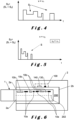
Figure 1 shows a schematic representation of an embodiment of an aerosol-generating article and an aerosol-generating device of the invention. The device comprises an optical system to detect an elongated indicium during the insertion movement V of an article in a device; -
Figures 2 illustrates a typical signal provided by a detection system of the device. The signal varies in function of the time of insertion and is provided by at least one detector that detects information provided by optical or non-optical effects provided by an indicium or array of indicia arranged on an article; -
Figure 3 illustrates an article comprising at least two indicia that are detected, at least partially during the insertion of an article into a device; -
Figures 4 and 5 illustrate typical signals provided by an indicium during the insertion movement of an article. The indicium comprises at least two different indicia detected and identified during the insertion of an article into a device; -
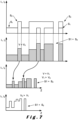
Figures 6 illustrates an article having a distributed indicium comprising a plurality and possibly different indicium elements, in particular detectable by different detection means e.g. electrical and optical detectors; -
Figures 7 illustrates a detailed view of the superposition of two signals as provided by an embodiment of an article as illustrated inFigure 3 . The figure illustrates that the shape of the superposed signals is independent of the acceleration of the insertion movement of an article into a device; -
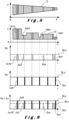
Figure 8 shows a wedge-shaped indicium according to the invention; -
Figure 9 illustrates a two-dimensional indicium comprising two orthogonal codes and the corresponding signals provided by the two orthogonal codes. A first code is a bar-like code arranged along the insertion direction of an article and the second code is realized by the detection of the variation of the width or thickness of the indicium; -
Figure 10 illustrates an indicium realized on a substrate layer. The figure illustrates that indicia elements may have different heights or widths or lengths, said height being defined in a radial direction orthogonal to the insertion direction of the article; -
Fig.11 illustrates an indicium comprising incoupling structures and outcoupling structures, the indicium being realized on a layer that has waveguiding properties. The figure illustrates also the incoupling and outcoupling of a light beam into and out the indicium layer. - The present invention will be described with respect to particular embodiments and with reference to the appended drawings, but the invention is not limited thereto. The drawings described are only schematic and are nonlimiting. In the drawings, the size of some of the elements may be exaggerated and not drawn on scale for illustrative purposes. The dimensions and the relative dimensions do not correspond to actual reductions to the practice of the invention.
- The invention will be described in the following examples in relation to tobacco-based consumable articles but the scope of the invention shall not be construed as limited to tobacco based consumable articles but shall encompass any aerosol-generating consumable articles, such as smoking articles, heat-not-burn articles, e-liquid cartridges and cartomizers, which comprises an aerosol-generating substrate capable to generate an inhalable aerosol upon heating. Aerosol-generating
articles 1 of the invention are also defined herein as articles or consumables or consumable articles. - As used herein, the term "aerosol-generating material" refers to a material capable of releasing upon heating volatile compounds, which can form an aerosol. The aerosol generated from aerosol-generating material of aerosol-generating articles described herein may be visible or invisible and may include vapours (for example, fine particles of substances, which are in a gaseous state, that are ordinarily liquid or solid at room temperature) as well as gases and liquid droplets of condensed vapours. Detailed composition of the aerosol generating substance may be tobacco, aerosol formers, binders, flavouring agents, nicotine and combinations thereof. An aerosol-forming substrate may be provided in a stable support. Such a support may be in the form of a powder, granules, strands, small strips, sheets or foam.
- The term "wrapper" is defined broadly as any structure or layer that protects and contains a charge of aerosol-generating material, and which allows to handle them. It has an inner surface that may be in contact with the aerosol-generating material and has an outer surface away from the aerosol-generating material. The wrapper 3 may preferably comprise a cellulose based material such as paper and/or cellulose acetate. The wrapper 3 may also be made of a biodegradable polymer or may be made of glass or a ceramic, and/or cellulose acetate. The wrapper 3 may be a porous material and may have a smooth or rough outer surface 5 and may be a flexible material or a hard material.
- The manufactured aerosol-generating
consumable article 1 may have a cross section of any regular or irregular shape, and can have, for example, an elliptical or circular cross-section, defined in a plane orthogonal to a longitudinal axis. - Herein the term "indicium" is a broad term that encompasses any layer or structure or element or configuration or layer or any geometrical and/or physical and/or or chemical property that may be used to identify the aerosol-generating article. The indicium is meant to be an element applied to or part of the aerosol-generating article that has the ability to de detected or read by a detection device for providing a signal of analog or digital form.
- The indicium of the invention is particularly configured to be readable during the introduction movement of the indicium in a device, by passing typically in front of or next to a
detector system 100. - Information in the indicium may be encoded in digital (e.g. binary) or analog manner.
- As used herein, the term "electrical effect" encompasses any effect produced by an electrical field or resistance of voltage or current or magnetic or induction effect. As used herein "an optical effect" encompasses any of: a colour, an intensity, a polarisation, a spectral, an interferometric, a transmission, a deviation or a reflection effect.
- There is provided a method to identify coded information arranged on an aerosol-generating
consumable article 1. Thearticle 1 defines an insertion direction Z and comprises at least oneindicium 10 containing coded information about thearticle 1 arranged on or inside saidarticle 1. - The method comprises the steps of:
- inserting the aerosol-generating article along the insertion direction Z in a
heating cavity 200 of an aerosol-generatingdevice 2 for receiving an aerosol-generatingconsumable article 1 said aerosol-generatingdevice 2 comprising anindicium detection system 100; - detecting said coded information in said
indicium 10 by the indicium detection system during the movement of insertion of said aerosol-generatingarticle 1 into theheating cavity 200 of said aerosol-generatingdevice 2 from aproximal end 2a of thecavity 200 to adistal end 2b of theheating cavity 200. - It is understood that a movement of the aerosol-generating article may be realized after the full insertion of the article in said cavity. The movement may be, for example, any back-and-forward movement of the aerosol-generating article after it has been inserted in the
cavity 200. - The detection of the
indicium 10 is realized by any optical and/or electrical effect as defined before. The detection of theindicium 10 is fully finished when the aerosol-generatingarticle 1 does not move anymore. In variants additional information on thearticle 1 may be retrieved during the movement of withdrawal of thearticle 1. -
Indicia 10 may have a continuous shape (Figure 8 ,10 ) in the length of an article or may be arranged according to a plurality of indicia elements 11-17 (Fig.1, 3 ,6 ,10 ) - In an embodiment said
indicium 10 is made of an array of optical layers arranged in the length of said insertion direction Z, and wherein saidindicium detection system 100 comprises at least one optical detector 130, 140. As further described, and illustrated inFig.6 , adetector system 100 may comprise two different detectors. In an embodiment at least one of said two detectors 130,140 may be a non-optical detector. For instance, a first detector is an optical detector and a second detector is an electrical detector, e.g. a capacitive, inductive or resistive detector. - Layers that may be used as a code or a support of an
indicium 10 are advantageously chosen amongst article layers such as one of: glue layers, bond, seam, separation layers, joining layers, overlapping layers. A layer may have also a single function as support layer of an indicium or array of indicia. - In advantageous embodiments indicia 10 are realized onto or into layers that may have typically one of the functions of:
- joining or adhesion;
- spacing between layers or elements;
- mechanical or humidity protecting, wrapping, rigidification and/or separation;
- airflow or cooling;
- friction reduction or enhancement skin of a user;
- optical and/or aesthetic functions.
- Indicia may also be arranged on parts or inserts or layers that are incorporated into or onto an article for the mere purpose of proving an indicium.
- In variants, a layer of an article may be used as an
indicium 10. Indeed, it is understood that typical manufacturing layers of anarticle 1, such as a paper wrapper or a glue layer, may be manufactured so that they conform to a predetermined shape, such as a triangular shape that may be identified during the introduction of an article in a device. The shaped part of such a layer may thus be used as anindicium 10 without requiring an added indicium layer onto or into anarticle 1. - In variants (not illustrated), an
indicium 10 may be formed by at least two straight lines or stripes that are arranged according to an angle relative to a longitudinal axis of anarticle 10. For example, anindicium 10 may comprise two thin lines or strips that are separated by a small distance or be in contact at the side of the consumable portion of an article, and having a greater separation at the side to the mouthpiece of an article. Such lines or stripes may have a curved shape and/or have a variable width. Said at least two straight lines or stripes may have an angle relative to each other or may even be crossing lines or stripes. In variants an indicium may comprise two thin lines that present a relative angle of less than 10°, preferably less than 5°, which is difficult to detect by the un-aided human eye. Such variant can also be combined with the embodiment ofFig.8 , further described, that comprises an additional longitudinal code, possible a bar code extending in the length of said two lines or strips. - In variants of all embodiments herein, the
layers 10 may have at least one of the following characteristics: - layers may comprise different parts having different lengths;
- a layer may overlap, at least partially, another layer that is also used as
indicium 10; - layers may have any 2D and/or 3D shape , the 2D shape being defined in the plane of the layer. Preferably a shape is defined by a polynomial, such as a triangle, a pentagon, an ellipse, or an oblong shape;
- layers may comprise at least two branches, such as a layer having a Y shape;
- layers comprise at least one aperture that may a through aperture extending from one side of the layer to an opposite side;
- have a variable width over a length of the layer, for example the variable width may be a series of continuous or discontinuous steps arranged over at least a portion of its length.
-
Indicia 10 may also be formed by a chemical treatment of a portion of a layer of aconsumable 1. For instance, a predetermined surface area of a wrapper may undergo a chemical etching or vapor deposition this partially etched or vapor deposited area may serve as anindicium 10. For example, etching may be used to realize a seam layer that has a variable width along a length of an article so that it may be detected when the article is introduced along acentral axis 204 of a cavity of a device. - In variants,
indicia 10 may be formed by a thickened predetermined area of a surface of anarticle 1. - In an embodiment, an
indicium 10 may be formed by at least two optical orelectrical layers 10, 10' that have different optical transmission or reflection properties, or different electrical properties. - In an embodiment said
indicium 10 is made of an array of successive conductive layers arranged in the length of said insertion direction Z and wherein saidindicium detection system 100 comprises at least oneelectrical detector 110. - In an embodiment said conductive layers are metallic layers. In an alternative, the layer is a graphite layer or a conductive ink layer. In variants a layer of an article may have a directional conductivity. For example, the conductivity may be different in two orthogonal directions. This may be realized for example by directional doping of the layers.
- In an embodiment said conductive layers are conductive ink layers 10.
- In embodiments, said conductive layers may be layers made of intrinsic conducting polymers (ICP). This allows to provide conductive layers that do not contain metallic compounds or metallic particles.
- In variants, different types of conductive layers may be implemented on or into the same
consumable article 1. - In an embodiment said electrical detector is configured to detect at least electrical capacitance between said conductive layers and said electrical detector.
- In an embodiment said electrical detector is configured to detect at least electrical inductance generated between said
conductive layers 10 and said electrical detector. - In an embodiment an
electrical detector 100 of the invention is configured to detect at least an electrical resistance between saidconductive layers 10 and said electrical detector. - In an embodiment said
indicium 10 is made of an array ofmagnetic layers 10 arranged in the length of said insertion direction Z, and wherein saidindicium detection system 100 comprises at least one magnetic detector configured to detect a magnetic field generated by said magnetic layers. - In an embodiment, illustrated in
Fig. 3 saidindicium 10 is made of at least a first array 10' and asecond array 10" of detectable layers that are both extending along or parallel to said insertion direction Z. As schematically illustrated inFigs. 4 and 5 the signals S1, S2 provided by the optical or electrical effect each of said at least a first array 10' and asecond array 10" of detectable layers are detected by at least onedetector 110, 110' and are superposed to provide a superposed signal S3 that provides a unique identification code identifying the aerosol-generatingconsumable article 1. Saiddetector 110, 110' may be an optical or electric or magnetic sensor but may also be a sensor that is configured to measure optical and electrical effects at the same time. For example, a sensor may detect a polarisation state and at the same time be configured as a Faraday effect sensor wherein the polarisation state changes upon an induced current, for example induced in a metallic layer or wire. -
Fig.7 illustrates a detailed view of two superposed signals S1, S2. The signal shape of the superposed signal S1+S2 presents a unique shape which is independent of the acceleration of the insertion movement of an article, as may be seen by comparing the shapes of the signal S1+S2 at speeds different V1 and V2 as illustrated inFig. 7 . The shape of the signal S1+S2 at a speed V2, which is greater than the speed V1, is identical. For example, even if the introduction movement of the article in a device is an accelerated movement, it is still possible to determine the over-all shape of the superposed signal S1+S2 , for example by counting the number of peaks and valleys. - In variants, detector schemes may be implemented to detect and correct for sudden backward movement , i.e. in the -Z direction, i.e. away from the
end 2b of thecavity 200. Such correction techniques are well known in the field of rotational or linear encoders and are not further described here. - In an embodiment wherein said
indicium detection system 100 comprises at least one electrical detector 130 and at least one optical detector 140. - In advantageous variants, illustrated in
Fig.6 , saidindicium 10 comprises at least one electrical detectable layer 10a and at least one opticaldetectable layer 10b, both layers being arranged along or parallel to said insertion direction Z, saidindicium detection system 100 comprising at least one electrical detector 130 and at least one optical detector 140. In a variant of the configuration ofFig.6 , saidindicium 10 comprises at least two different opticaldetectable layer 10a, 10b and the two detectors 130, 140 are different optical detectors. A detector 130, 140 may be detector comprising a color filter or an interference filter. In all embodiments of the invention anoptical detection system 100 may comprise optical means to measure spectral characteristics, such as a spectrometer or refractive or diffractive dispersion elements. An optical detection system may comprise mirrors to send collected light to a detector 130, 140 that is placed at a distance to the portion of the layer that provides optical information such as its spectral characteristic. In a variant a detector may be arranged to adistal end 2b of thecavity 200. - In embodiments the indicium may be made so that it comprises at least two codes that may be codes that have a predetermined angle. For example,
Fig.8 illustrates a conical shaped indicium that has a varying width. A code, such as a bar-code , may be incorporated into or onto the layer of the indicium so that not only the longitudinal distribution of code elements constitutes a readable code, but the code may be complexified by adding information on the variation of the width of the indicia, as illustrated schematically inFig.8 . - In an advantageous variant, an indicium may have a wedge shape and at least one of its sides may comprise step structure such as illustrated in the example of
Fig.9. Fig.9 illustrates how a first signal Sz may be provided in relation with the longitudinal distribution ofcode elements indicium 10.Fig.9 shows exemplary signals Sz1, Sz4, Sz7, Sz10 corresponding to longitudinal-orientedcode elements Fig.9 . The sum of the signals Sx related to the longitudinal code elements and the signals Sy related to the information on the variation of width or presence of steps constitute a code signal S1+S2 that comprises much more information than simpler codes such as the one illustrated inFig.1 . - In variants, to further complexify a code, information on the variable thickness of successive indicia elements having different thicknesses may be provided, such as illustrated in
Fig. 10 . The indicia elements are positioned in an array in the direction of direction Z, e.g. parallel to the longitudinal axis of the article as illustrated inFig. 10 . The thickness of each element is determined orthogonally to the insertion direction Z or to a tangent to the surface of the article, e.g. radial to the surface of a rod-shaped article. In variants, indicia elements 11-19 may be realized directly into the material of thelayer 20. Indicia may be realized inside or onto at least one side of the material of thelayer 20 for example by a pressing tool during the manufacturing of an article. The thickness may also vary between two parallel arrays of layers. For example, a first array may have layers with first thicknesses t1, t2, t3 and the second array have layers with second thicknesses t4, t5, t6. -
Fig.11 illustrates an indicium that is made of a layer that is configured to provide internal reflected light, similar to the reflection inside a prism or a pentaprism. This allows to provide signals that depend on the way an article is introduced in a device, for example it may provide information on the depth of introduction of an article in acavity 200. Thelight source 300 and thedetector system 100 in the embodiment ofFig.11 may be configured so that it detects alayer 10 arranged at the distal end of an article. For example, as long as the distal end comprising the layer does not provide a signal to thedetector 110, thedevice 2 may not allow to trigger the start of use of thedevice 2. - In variants,
indicia 10 of the invention may have optical properties such as light focusing, light diverging properties. In variants, indicia may provide a signal related to changes of color, polarization and optical scattering effects, or a combination of such optical effects. It is generally understood herein that a variety of detection schemes or imaging methods may be applied to detect and/or image theindicium 10 orindicium layer 10 of the invention image processing techniques in the invention may be simple contrast enhancing techniques or very advanced. Image processing methods such as used in any high security detection systems, for example as used in banking or in fingerprint recognition. In variants 2D and/or 3D imaging may be used to detect and interpret the information imbedded in theindicium 10. For example, 3D imaging techniques may be used to detect the height variations of indicia elements, such as the elements 11-19 illustrated inFig.10 . In variants, optical depth probes may be applied to detect the indicia. Such probes are optical devices that provide information on a depth or a depth profile of a structures, here an indicium structure. Also, interferometric optical techniques may be used in thedetection system 100, 100' of the invention. - Any advanced imaging and/or imaging processing technique may be used to detect an indicium. Image processing comprising feature extraction techniques are well known in the field of 2D and 3D image processing and are not further described here.
- It is referred therefor to the following publications:
- R.Szeliski, Computer vision: Algorithms and Applications, Springer Verlag, 2010, ISBN 978-1848829343 ;
- J.R.Parker, Algorithms for image processing and Computer Vision (2nd ed.), Wiley, 2011, ISBN 978-0470643853;
- N.Mark, A.Aguado, Feature Extraction and Image Processing for Computer Vision (4the ed.), Academic Press, 2019, ISBN 978-0128149768.
- There is also provided an aerosol-generating
device 2 comprising, arranged in an outer body a power supply section (not illustrated) and acavity 200 defining acavity axis 204, said body having an opening accessible at the outer body and being configured to receive aconsumable article 1 defining an insertion direction Z. - The aerosol-generating
device 2 further comprises anindicium detection system 100 configured arranged in thedevice 2 to detect said readable code optically and/or electrically during the insertion movement of saidarticle 1 into saidcavity 200 from aproximal end 2a to adistal end 2b thereof. - There is also provided an aerosol-generating
article 1 defining an insertion direction Z and comprising at least oneindicium 10 containing coded information about thearticle 1, saidindicium 10 and said coded information being arranged along or parallel to said insertion direction Z for being readable by anindicium detection system 100 of an aerosol-generatingdevice 2 during the movement of insertion of said aerosol-generatingarticle 1 into said aerosol-generatingdevice 2. - There is also provided an aerosol-generating system comprising an at least partially inserted aerosol-generating
articles 1 and said aerosol-generatingdevice 2.
Claims (16)
- Method for identifying coded information arranged on an aerosol-generating consumable article (1) to be consumed by using an aerosol generating device, the article (1) defining an insertion direction (Z) and comprising at least one indicium (10) containing coded information about the article (1) arranged on or inside said article (1), the aerosol-generating device (2) comprising a cavity (200) arranged for insertion of the article (1) along the insertion direction (Z) and comprising an indicium detection system (100), the method comprising:
reading the coded information of said indicium (10) by the indicium detection system (100) only during the lapse of time of the movement of insertion of said aerosol-generating article (1) in the cavity (200), as the article (1) is moved in or through the cavity (200) of said aerosol-generating device (2). - The method according to claim 1, wherein said indicium (10) comprises an array of optical layers arranged in the length of said insertion direction (Z), and wherein said indicium detection system (100) comprises at least one optical detector (110).
- The method according to claim 2, wherein at least two of the optical layers have different optical transmission and/or reflection and/or absorption and/or scattering and/or diffraction and/or polarisation properties.
- The method according to one of claims 1 to 3, wherein the indicium (10) comprises an array of electrically conductive layers arranged in the length of said insertion direction (Z), and wherein the indicium detection system (100) comprises at least one electrical detector (110).
- The method according to claim 4, wherein said conductive layers (10) are metallic layers.
- The method according to claim 4 or 5, wherein said conductive layers (10) are conductive ink layers, preferably metal ink layers.
- The method according to claim 4, wherein said conductive layers (10) are intrinsic conductive polymer (ICP) layers.
- The method according to any one of claims 4 to 7, wherein the electrical detector is configured to detect an electrical capacitance between the conductive layers and the electrical detector.
- The method according to any one of claims 4 to 7, wherein the electrical detector (100) is configured to detect an electrical inductance generated between the conductive layers and the electrical detector.
- The method according to any one of claims 4 to 7, wherein the electrical detector (100) is configured to detect an electrical resistance between the conductive layers (10) and the electrical detector (100).
- The method according to claim 1, wherein the indicium (10) comprises an array of magnetic layers arranged in the length of said insertion direction (Z), and wherein the indicium detection system comprises at least one magnetic detector configured to detect a magnetic field generated by said magnetic layers.
- The method according to any one of claims 1 to 11, wherein the indicium (10) comprises at least a first array (10') and a second array (10") of detectable layers that are both extending along or parallel to said insertion direction (Z), and wherein the signals (S1, S2) produced by each of said at least first array (10') and second array (10") of detectable layers are detected by at least one optical detector (110, 110') and are, preferably, superposed to provide a superposed signal (S3) that provides a unique identification code identifying the aerosol-generating consumable article (1).
- The method according to any one of claims 1 to 12, wherein the indicium detection system (100) comprises at least one electrical detector (130) and at least one optical detector (140).
- The method according to any one of claims 1 to 13, wherein the indicium (10) comprises at least one electrically detectable layer (10a) and at least one optically detectable layer (10b), both layers being arranged along or parallel to said insertion direction (Z), said indicium detection system (100) comprising at least one electrical detector (130) and at least one optical detector (140).
- An aerosol-generating device (2) comprising, arranged in an outer body , a power supply section and a cavity (200) defining a cavity axis (204), said body having an opening accessible at the outer body and being configured to receive a consumable article (1) defining an insertion direction (Z) and comprising at least one indicium (10) containing coded information about the article (1) arranged on or inside said article (1), the aerosol-generating device (2) comprising an indicium detection system (100),
wherein the indicium detection system (100) is configured in the device to read said coded information optically and/or electrically only during the lapse of time of the movement of insertion of said aerosol-generating article (1) in the cavity (200).as the article moves in or through the cavity (200). - An aerosol-generating system comprising said aerosol-generating device (2) according to claim 15 and an aerosol-generating article (1), at least partially inserted in said aerosol-generating device (2), the aerosol-generating article (1) defining an insertion direction (Z) and comprising at least one indicium (10) containing coded information about the article (1), said indicium (10) being arranged in the insertion direction (Z), for being read by said indicium detection system (100) only during the lapse of time of the movement of insertion of said aerosol-generating article (1) in said cavity (200) as the article moves in or through the cavity (200).
Priority Applications (1)
| Application Number | Priority Date | Filing Date | Title |
|---|---|---|---|
| EP25168481.7A EP4578314A3 (en) | 2020-06-12 | 2021-06-01 | Method and system for identifying aerosol-generating articles |
Applications Claiming Priority (2)
| Application Number | Priority Date | Filing Date | Title |
|---|---|---|---|
| EP20179617 | 2020-06-12 | ||
| PCT/EP2021/064719 WO2021249833A1 (en) | 2020-06-12 | 2021-06-01 | Method and system for identifying aerosol-generating articles |
Related Child Applications (1)
| Application Number | Title | Priority Date | Filing Date |
|---|---|---|---|
| EP25168481.7A Division EP4578314A3 (en) | 2020-06-12 | 2021-06-01 | Method and system for identifying aerosol-generating articles |
Publications (3)
| Publication Number | Publication Date |
|---|---|
| EP4164436A1 EP4164436A1 (en) | 2023-04-19 |
| EP4164436C0 EP4164436C0 (en) | 2025-04-09 |
| EP4164436B1 true EP4164436B1 (en) | 2025-04-09 |
Family
ID=71094116
Family Applications (2)
| Application Number | Title | Priority Date | Filing Date |
|---|---|---|---|
| EP25168481.7A Pending EP4578314A3 (en) | 2020-06-12 | 2021-06-01 | Method and system for identifying aerosol-generating articles |
| EP21730188.6A Active EP4164436B1 (en) | 2020-06-12 | 2021-06-01 | Method and system for identifying aerosol-generating articles |
Family Applications Before (1)
| Application Number | Title | Priority Date | Filing Date |
|---|---|---|---|
| EP25168481.7A Pending EP4578314A3 (en) | 2020-06-12 | 2021-06-01 | Method and system for identifying aerosol-generating articles |
Country Status (4)
| Country | Link |
|---|---|
| EP (2) | EP4578314A3 (en) |
| JP (1) | JP7734702B2 (en) |
| PL (1) | PL4164436T3 (en) |
| WO (1) | WO2021249833A1 (en) |
Families Citing this family (6)
| Publication number | Priority date | Publication date | Assignee | Title |
|---|---|---|---|---|
| JP7210731B2 (en) * | 2020-01-06 | 2023-01-23 | ケーティー アンド ジー コーポレイション | Aerosol generation system |
| EP4458175A4 (en) * | 2021-12-28 | 2026-01-21 | Japan Tobacco Inc | NON-COMBUSTION AROMA HOLDER |
| CN217592037U (en) * | 2022-02-24 | 2022-10-18 | 比亚迪精密制造有限公司 | Electromagnetic induction piece, heating device and electron cigarette |
| CN117137201A (en) * | 2023-08-25 | 2023-12-01 | 爱奇迹(香港)有限公司 | Control method, control system and atomization device of atomization device |
| WO2026003103A1 (en) * | 2024-06-25 | 2026-01-02 | Philip Morris Products S.A. | Aerosol-generating device with authentification and identification for aerosol-generating articles |
| EP4670527A3 (en) * | 2024-06-25 | 2026-02-11 | Philip Morris Products S.A. | Aerosol-generating device with authentification and identification for aerosol-generating articles |
Citations (30)
| Publication number | Priority date | Publication date | Assignee | Title |
|---|---|---|---|---|
| WO1999020132A1 (en) | 1997-10-16 | 1999-04-29 | Philip Morris Products Inc. | Lighter actuation system |
| WO1999020940A1 (en) | 1997-10-20 | 1999-04-29 | Philip Morris Products Inc. | Lighter actuation system |
| US6354501B1 (en) | 1998-11-18 | 2002-03-12 | Crossoff Incorporated | Composite authentication mark and system and method for reading the same |
| EP2201850A1 (en) | 2008-12-24 | 2010-06-30 | Philip Morris Products S.A. | An article including identification information for use in an electrically heated smoking system |
| US20130072897A1 (en) | 2010-01-22 | 2013-03-21 | Sanofi-Aventis Deutschland Gmbh | Method and system for determining information related to a drug reservoir |
| US20130221097A1 (en) | 2010-08-19 | 2013-08-29 | Sanofi-Aventis Deutschland Gmbh | Method and system for determining information related to a drug reservoir using an electronic sensor |
| WO2013182673A1 (en) | 2012-06-08 | 2013-12-12 | Eibensteiner Friedrich | Method for producing products which are printed with information and which comprise a lighting element |
| WO2015082560A1 (en) | 2013-12-03 | 2015-06-11 | Philip Morris Products S.A. | Aerosol-generating article and electrically operated system incorporating a taggant |
| WO2015088290A2 (en) | 2013-12-13 | 2015-06-18 | 황일영 | Atomization device |
| WO2016075436A1 (en) | 2014-11-11 | 2016-05-19 | Relco Induction Developments Limited | Electronic vapour inhalers |
| US20160345628A1 (en) | 2014-02-24 | 2016-12-01 | Arash Abdollahi Sabet | Electronic cigarette and cigar charging and operating systems integration with various cell phone and tablet types using a common case |
| WO2017005471A1 (en) | 2015-07-09 | 2017-01-12 | Philip Morris Products S.A. | Heater assembly for an aerosol-generating system |
| WO2017029089A1 (en) | 2015-08-14 | 2017-02-23 | Philip Morris Products S.A. | An electrically operated smoking device including a compact system for identifying smoking articles in the device |
| US20170360088A1 (en) | 2014-12-16 | 2017-12-21 | Philip Morris Products S.A. | Tobacco sachet for use in a tobacco vaporizer |
| US20180049469A1 (en) | 2014-03-21 | 2018-02-22 | British American Tobacco (Investments) Limited | Apparatus for heating smokable material and article of smokable material |
| US20190008206A1 (en) | 2015-08-14 | 2019-01-10 | Philip Morris Products S.A. | An electrically operated smoking device including a system for identifying smoking articles in the device |
| US20190053538A1 (en) | 2015-06-12 | 2019-02-21 | Philip Morris Products S.A. | Product recognition in aerosol generating devices |
| WO2019092889A1 (en) | 2017-11-13 | 2019-05-16 | 日本たばこ産業株式会社 | Circuit board for non-combustion type flavor inhaler and non-combustion type flavor inhaler |
| WO2019129378A1 (en) | 2017-12-29 | 2019-07-04 | Jt International S.A. | Inhaler with optical recognition and consumable therefor |
| WO2019185748A1 (en) | 2018-03-29 | 2019-10-03 | Nicoventures Trading Limited | Apparatus for generating aerosol from an aerosolisable medium and article of aerosolisable medium |
| WO2019185747A1 (en) | 2018-03-29 | 2019-10-03 | Nicoventures Trading Limited | Apparatus for generating aerosol from an aerosolisable medium, an article of aerosolisable medium and a method of operating an aerosol generating apparatus |
| WO2019185744A1 (en) | 2018-03-29 | 2019-10-03 | Nicoventures Trading Limited | Apparatus for generating aerosol from an aerosolisable medium, an article of aerosolisable medium and a method of determining a parameter of an article |
| WO2019185749A1 (en) | 2018-03-29 | 2019-10-03 | Nicoventures Trading Limited | Apparatus for generating aerosol from an aerosolisable medium, an article of aerosolisable medium and a method of operating an aerosol generating apparatus |
| US20190380388A1 (en) | 2018-06-15 | 2019-12-19 | Pax Labs, Inc. | Session control for a vaporizer device |
| WO2020001446A1 (en) | 2018-06-29 | 2020-01-02 | 深圳御烟实业有限公司 | Aerosol generating product, apparatus and system |
| WO2020035587A1 (en) | 2018-08-17 | 2020-02-20 | Philip Morris Products S.A. | Aerosol-generating device for use with an aerosol-generating article comprising means for article identification |
| WO2020105896A1 (en) | 2018-11-23 | 2020-05-28 | 주식회사 케이티앤지 | Aerosol generating device and method for operating same |
| WO2020152289A1 (en) | 2019-01-25 | 2020-07-30 | Nicoventures Trading Limited | Aerosol generating apparatus, aerosol generating article and method of determining data associated with an aerosol generating article |
| WO2020249661A1 (en) | 2019-06-14 | 2020-12-17 | Philip Morris Products S.A. | Aerosol-generating device with optical means for state detection |
| WO2021250184A1 (en) | 2020-06-12 | 2021-12-16 | Jt International S.A. | Consumable for aerosol generation device comprising information code and aerosol generation device detecting it |
Family Cites Families (1)
| Publication number | Priority date | Publication date | Assignee | Title |
|---|---|---|---|---|
| CN109068753B (en) | 2016-05-31 | 2025-09-23 | 菲利普莫里斯生产公司 | Electrically operated aerosol generating system having means for detecting a tubular aerosol-generating article |
-
2021
- 2021-06-01 WO PCT/EP2021/064719 patent/WO2021249833A1/en not_active Ceased
- 2021-06-01 PL PL21730188.6T patent/PL4164436T3/en unknown
- 2021-06-01 JP JP2022576045A patent/JP7734702B2/en active Active
- 2021-06-01 EP EP25168481.7A patent/EP4578314A3/en active Pending
- 2021-06-01 EP EP21730188.6A patent/EP4164436B1/en active Active
Patent Citations (33)
| Publication number | Priority date | Publication date | Assignee | Title |
|---|---|---|---|---|
| WO1999020132A1 (en) | 1997-10-16 | 1999-04-29 | Philip Morris Products Inc. | Lighter actuation system |
| WO1999020940A1 (en) | 1997-10-20 | 1999-04-29 | Philip Morris Products Inc. | Lighter actuation system |
| US6354501B1 (en) | 1998-11-18 | 2002-03-12 | Crossoff Incorporated | Composite authentication mark and system and method for reading the same |
| EP2201850A1 (en) | 2008-12-24 | 2010-06-30 | Philip Morris Products S.A. | An article including identification information for use in an electrically heated smoking system |
| US8689804B2 (en) | 2008-12-24 | 2014-04-08 | Philip Morris Usa Inc. | Article including identification information for use in an electrically heated smoking system |
| US20130072897A1 (en) | 2010-01-22 | 2013-03-21 | Sanofi-Aventis Deutschland Gmbh | Method and system for determining information related to a drug reservoir |
| US20130221097A1 (en) | 2010-08-19 | 2013-08-29 | Sanofi-Aventis Deutschland Gmbh | Method and system for determining information related to a drug reservoir using an electronic sensor |
| WO2013182673A1 (en) | 2012-06-08 | 2013-12-12 | Eibensteiner Friedrich | Method for producing products which are printed with information and which comprise a lighting element |
| WO2015082560A1 (en) | 2013-12-03 | 2015-06-11 | Philip Morris Products S.A. | Aerosol-generating article and electrically operated system incorporating a taggant |
| US10555555B2 (en) | 2013-12-03 | 2020-02-11 | Philip Morris Products S.A. | Aerosol-generating article and electrically operated system incorporating a taggant |
| WO2015088290A2 (en) | 2013-12-13 | 2015-06-18 | 황일영 | Atomization device |
| US20160345628A1 (en) | 2014-02-24 | 2016-12-01 | Arash Abdollahi Sabet | Electronic cigarette and cigar charging and operating systems integration with various cell phone and tablet types using a common case |
| US20180049469A1 (en) | 2014-03-21 | 2018-02-22 | British American Tobacco (Investments) Limited | Apparatus for heating smokable material and article of smokable material |
| WO2016075436A1 (en) | 2014-11-11 | 2016-05-19 | Relco Induction Developments Limited | Electronic vapour inhalers |
| US20170360088A1 (en) | 2014-12-16 | 2017-12-21 | Philip Morris Products S.A. | Tobacco sachet for use in a tobacco vaporizer |
| US20190053538A1 (en) | 2015-06-12 | 2019-02-21 | Philip Morris Products S.A. | Product recognition in aerosol generating devices |
| WO2017005471A1 (en) | 2015-07-09 | 2017-01-12 | Philip Morris Products S.A. | Heater assembly for an aerosol-generating system |
| US20190008206A1 (en) | 2015-08-14 | 2019-01-10 | Philip Morris Products S.A. | An electrically operated smoking device including a system for identifying smoking articles in the device |
| WO2017029089A1 (en) | 2015-08-14 | 2017-02-23 | Philip Morris Products S.A. | An electrically operated smoking device including a compact system for identifying smoking articles in the device |
| WO2019092889A1 (en) | 2017-11-13 | 2019-05-16 | 日本たばこ産業株式会社 | Circuit board for non-combustion type flavor inhaler and non-combustion type flavor inhaler |
| WO2019129378A1 (en) | 2017-12-29 | 2019-07-04 | Jt International S.A. | Inhaler with optical recognition and consumable therefor |
| WO2019185748A1 (en) | 2018-03-29 | 2019-10-03 | Nicoventures Trading Limited | Apparatus for generating aerosol from an aerosolisable medium and article of aerosolisable medium |
| WO2019185747A1 (en) | 2018-03-29 | 2019-10-03 | Nicoventures Trading Limited | Apparatus for generating aerosol from an aerosolisable medium, an article of aerosolisable medium and a method of operating an aerosol generating apparatus |
| WO2019185744A1 (en) | 2018-03-29 | 2019-10-03 | Nicoventures Trading Limited | Apparatus for generating aerosol from an aerosolisable medium, an article of aerosolisable medium and a method of determining a parameter of an article |
| WO2019185749A1 (en) | 2018-03-29 | 2019-10-03 | Nicoventures Trading Limited | Apparatus for generating aerosol from an aerosolisable medium, an article of aerosolisable medium and a method of operating an aerosol generating apparatus |
| US20190380388A1 (en) | 2018-06-15 | 2019-12-19 | Pax Labs, Inc. | Session control for a vaporizer device |
| WO2020001446A1 (en) | 2018-06-29 | 2020-01-02 | 深圳御烟实业有限公司 | Aerosol generating product, apparatus and system |
| EP3815557A1 (en) | 2018-06-29 | 2021-05-05 | Shenzhen Yuyan Industrial Limited | Aerosol generating product, apparatus and system |
| WO2020035587A1 (en) | 2018-08-17 | 2020-02-20 | Philip Morris Products S.A. | Aerosol-generating device for use with an aerosol-generating article comprising means for article identification |
| WO2020105896A1 (en) | 2018-11-23 | 2020-05-28 | 주식회사 케이티앤지 | Aerosol generating device and method for operating same |
| WO2020152289A1 (en) | 2019-01-25 | 2020-07-30 | Nicoventures Trading Limited | Aerosol generating apparatus, aerosol generating article and method of determining data associated with an aerosol generating article |
| WO2020249661A1 (en) | 2019-06-14 | 2020-12-17 | Philip Morris Products S.A. | Aerosol-generating device with optical means for state detection |
| WO2021250184A1 (en) | 2020-06-12 | 2021-12-16 | Jt International S.A. | Consumable for aerosol generation device comprising information code and aerosol generation device detecting it |
Non-Patent Citations (1)
| Title |
|---|
| ANONYMOUS: "Conductive polymer", WIKIPEDIA, 5 June 2020 (2020-06-05), XP093357456, Retrieved from the Internet <URL:https://en.wikipedia.org/w/index.php?title=Conductive_polymer&oldid=960802446> |
Also Published As
| Publication number | Publication date |
|---|---|
| EP4164436C0 (en) | 2025-04-09 |
| EP4578314A2 (en) | 2025-07-02 |
| JP7734702B2 (en) | 2025-09-05 |
| EP4164436A1 (en) | 2023-04-19 |
| EP4578314A3 (en) | 2025-08-27 |
| WO2021249833A1 (en) | 2021-12-16 |
| JP2023528685A (en) | 2023-07-05 |
| PL4164436T3 (en) | 2025-09-01 |
Similar Documents
| Publication | Publication Date | Title |
|---|---|---|
| EP4164436B1 (en) | Method and system for identifying aerosol-generating articles | |
| RU2762357C1 (en) | Device for producing an aerosol from an aerosol-forming substance, an aerosol-forming substance product and a method for determining the product parameter | |
| JP7703572B2 (en) | Method and system for identifying smoking articles | |
| CN116898142A (en) | Devices for generating aerosols from aerosolizable media, articles of aerosolizable media, and methods of operating aerosol-generating devices | |
| WO2021249834A1 (en) | Method and system for identifying smoking articles | |
| JP2023513207A (en) | Aerosol delivery device, aerosol generating article and aerosol delivery system | |
| CN115697094A (en) | Consumable for an aerosol-generating device comprising an information code and aerosol-generating device for detecting the information code | |
| WO2021122524A1 (en) | An electrically operated smoking device including a system for identifying smoking articles comprising an indicium | |
| EP4164423B1 (en) | Aerosol-generating article and device for identifying a smoking article | |
| KR20200068202A (en) | A smoking article including identification information and an electrically smoking apparatus thereby | |
| JP7775281B2 (en) | Electrically operated smoking device with a system for identifying smoking articles including indicia - Patent Application 20070122997 |
Legal Events
| Date | Code | Title | Description |
|---|---|---|---|
| STAA | Information on the status of an ep patent application or granted ep patent |
Free format text: STATUS: UNKNOWN |
|
| STAA | Information on the status of an ep patent application or granted ep patent |
Free format text: STATUS: THE INTERNATIONAL PUBLICATION HAS BEEN MADE |
|
| PUAI | Public reference made under article 153(3) epc to a published international application that has entered the european phase |
Free format text: ORIGINAL CODE: 0009012 |
|
| STAA | Information on the status of an ep patent application or granted ep patent |
Free format text: STATUS: REQUEST FOR EXAMINATION WAS MADE |
|
| 17P | Request for examination filed |
Effective date: 20221219 |
|
| AK | Designated contracting states |
Kind code of ref document: A1 Designated state(s): AL AT BE BG CH CY CZ DE DK EE ES FI FR GB GR HR HU IE IS IT LI LT LU LV MC MK MT NL NO PL PT RO RS SE SI SK SM TR |
|
| DAV | Request for validation of the european patent (deleted) | ||
| DAX | Request for extension of the european patent (deleted) | ||
| GRAP | Despatch of communication of intention to grant a patent |
Free format text: ORIGINAL CODE: EPIDOSNIGR1 |
|
| STAA | Information on the status of an ep patent application or granted ep patent |
Free format text: STATUS: GRANT OF PATENT IS INTENDED |
|
| RIC1 | Information provided on ipc code assigned before grant |
Ipc: A24F 40/20 20200101ALN20241017BHEP Ipc: A24F 40/53 20200101ALI20241017BHEP Ipc: A24F 40/51 20200101AFI20241017BHEP |
|
| INTG | Intention to grant announced |
Effective date: 20241104 |
|
| GRAS | Grant fee paid |
Free format text: ORIGINAL CODE: EPIDOSNIGR3 |
|
| GRAA | (expected) grant |
Free format text: ORIGINAL CODE: 0009210 |
|
| STAA | Information on the status of an ep patent application or granted ep patent |
Free format text: STATUS: THE PATENT HAS BEEN GRANTED |
|
| AK | Designated contracting states |
Kind code of ref document: B1 Designated state(s): AL AT BE BG CH CY CZ DE DK EE ES FI FR GB GR HR HU IE IS IT LI LT LU LV MC MK MT NL NO PL PT RO RS SE SI SK SM TR |
|
| REG | Reference to a national code |
Ref country code: GB Ref legal event code: FG4D |
|
| REG | Reference to a national code |
Ref country code: CH Ref legal event code: EP |
|
| REG | Reference to a national code |
Ref country code: DE Ref legal event code: R096 Ref document number: 602021028914 Country of ref document: DE |
|
| REG | Reference to a national code |
Ref country code: IE Ref legal event code: FG4D |
|
| U01 | Request for unitary effect filed |
Effective date: 20250508 |
|
| U07 | Unitary effect registered |
Designated state(s): AT BE BG DE DK EE FI FR IT LT LU LV MT NL PT RO SE SI Effective date: 20250514 |
|
| PGFP | Annual fee paid to national office [announced via postgrant information from national office to epo] |
Ref country code: GB Payment date: 20250618 Year of fee payment: 5 |
|
| U20 | Renewal fee for the european patent with unitary effect paid |
Year of fee payment: 5 Effective date: 20250627 |
|
| PG25 | Lapsed in a contracting state [announced via postgrant information from national office to epo] |
Ref country code: ES Free format text: LAPSE BECAUSE OF FAILURE TO SUBMIT A TRANSLATION OF THE DESCRIPTION OR TO PAY THE FEE WITHIN THE PRESCRIBED TIME-LIMIT Effective date: 20250409 |
|
| PG25 | Lapsed in a contracting state [announced via postgrant information from national office to epo] |
Ref country code: GR Free format text: LAPSE BECAUSE OF FAILURE TO SUBMIT A TRANSLATION OF THE DESCRIPTION OR TO PAY THE FEE WITHIN THE PRESCRIBED TIME-LIMIT Effective date: 20250710 Ref country code: NO Free format text: LAPSE BECAUSE OF FAILURE TO SUBMIT A TRANSLATION OF THE DESCRIPTION OR TO PAY THE FEE WITHIN THE PRESCRIBED TIME-LIMIT Effective date: 20250709 |
|
| PGFP | Annual fee paid to national office [announced via postgrant information from national office to epo] |
Ref country code: PL Payment date: 20250602 Year of fee payment: 5 |
|
| PG25 | Lapsed in a contracting state [announced via postgrant information from national office to epo] |
Ref country code: HR Free format text: LAPSE BECAUSE OF FAILURE TO SUBMIT A TRANSLATION OF THE DESCRIPTION OR TO PAY THE FEE WITHIN THE PRESCRIBED TIME-LIMIT Effective date: 20250409 |
|
| PGFP | Annual fee paid to national office [announced via postgrant information from national office to epo] |
Ref country code: CH Payment date: 20250701 Year of fee payment: 5 |
|
| PG25 | Lapsed in a contracting state [announced via postgrant information from national office to epo] |
Ref country code: RS Free format text: LAPSE BECAUSE OF FAILURE TO SUBMIT A TRANSLATION OF THE DESCRIPTION OR TO PAY THE FEE WITHIN THE PRESCRIBED TIME-LIMIT Effective date: 20250709 |
|
| PG25 | Lapsed in a contracting state [announced via postgrant information from national office to epo] |
Ref country code: IS Free format text: LAPSE BECAUSE OF FAILURE TO SUBMIT A TRANSLATION OF THE DESCRIPTION OR TO PAY THE FEE WITHIN THE PRESCRIBED TIME-LIMIT Effective date: 20250809 |
|
| PG25 | Lapsed in a contracting state [announced via postgrant information from national office to epo] |
Ref country code: SM Free format text: LAPSE BECAUSE OF FAILURE TO SUBMIT A TRANSLATION OF THE DESCRIPTION OR TO PAY THE FEE WITHIN THE PRESCRIBED TIME-LIMIT Effective date: 20250409 |
|
| PLBI | Opposition filed |
Free format text: ORIGINAL CODE: 0009260 |
|
| PG25 | Lapsed in a contracting state [announced via postgrant information from national office to epo] |
Ref country code: CZ Free format text: LAPSE BECAUSE OF FAILURE TO SUBMIT A TRANSLATION OF THE DESCRIPTION OR TO PAY THE FEE WITHIN THE PRESCRIBED TIME-LIMIT Effective date: 20250409 |
|
| REG | Reference to a national code |
Ref country code: CH Ref legal event code: L10 Free format text: ST27 STATUS EVENT CODE: U-0-0-L10-L00 (AS PROVIDED BY THE NATIONAL OFFICE) Effective date: 20260121 |
|
| PLAX | Notice of opposition and request to file observation + time limit sent |
Free format text: ORIGINAL CODE: EPIDOSNOBS2 |
|
| PG25 | Lapsed in a contracting state [announced via postgrant information from national office to epo] |
Ref country code: SK Free format text: LAPSE BECAUSE OF FAILURE TO SUBMIT A TRANSLATION OF THE DESCRIPTION OR TO PAY THE FEE WITHIN THE PRESCRIBED TIME-LIMIT Effective date: 20250409 |
|
| PG25 | Lapsed in a contracting state [announced via postgrant information from national office to epo] |
Ref country code: MC Free format text: LAPSE BECAUSE OF FAILURE TO SUBMIT A TRANSLATION OF THE DESCRIPTION OR TO PAY THE FEE WITHIN THE PRESCRIBED TIME-LIMIT Effective date: 20250409 |
|
| 26 | Opposition filed |
Opponent name: PHILIP MORRIS PRODUCTS S.A. Effective date: 20260108 Opponent name: NICOVENTURES TRADING LIMITED Effective date: 20260109 |
|
| U1N | Appointed representative for the unitary patent procedure changed after the registration of the unitary effect |
Representative=s name: KILBURN & STRODE LLP; GB |
|
| PG25 | Lapsed in a contracting state [announced via postgrant information from national office to epo] |
Ref country code: IE Free format text: LAPSE BECAUSE OF NON-PAYMENT OF DUE FEES Effective date: 20250601 |