EP4164363A1 - Organic light emitting diode and organic light emitting device including the same - Google Patents
Organic light emitting diode and organic light emitting device including the same Download PDFInfo
- Publication number
- EP4164363A1 EP4164363A1 EP22199762.0A EP22199762A EP4164363A1 EP 4164363 A1 EP4164363 A1 EP 4164363A1 EP 22199762 A EP22199762 A EP 22199762A EP 4164363 A1 EP4164363 A1 EP 4164363A1
- Authority
- EP
- European Patent Office
- Prior art keywords
- group
- compound
- unsubstituted
- substituted
- formula
- Prior art date
- Legal status (The legal status is an assumption and is not a legal conclusion. Google has not performed a legal analysis and makes no representation as to the accuracy of the status listed.)
- Granted
Links
Images




Classifications
-
- H—ELECTRICITY
- H10—SEMICONDUCTOR DEVICES; ELECTRIC SOLID-STATE DEVICES NOT OTHERWISE PROVIDED FOR
- H10K—ORGANIC ELECTRIC SOLID-STATE DEVICES
- H10K85/00—Organic materials used in the body or electrodes of devices covered by this subclass
- H10K85/30—Coordination compounds
- H10K85/341—Transition metal complexes, e.g. Ru(II)polypyridine complexes
- H10K85/342—Transition metal complexes, e.g. Ru(II)polypyridine complexes comprising iridium
-
- C—CHEMISTRY; METALLURGY
- C09—DYES; PAINTS; POLISHES; NATURAL RESINS; ADHESIVES; COMPOSITIONS NOT OTHERWISE PROVIDED FOR; APPLICATIONS OF MATERIALS NOT OTHERWISE PROVIDED FOR
- C09K—MATERIALS FOR MISCELLANEOUS APPLICATIONS, NOT PROVIDED FOR ELSEWHERE
- C09K11/00—Luminescent materials, e.g. electroluminescent or chemiluminescent
- C09K11/06—Luminescent materials, e.g. electroluminescent or chemiluminescent containing organic luminescent materials
-
- H—ELECTRICITY
- H10—SEMICONDUCTOR DEVICES; ELECTRIC SOLID-STATE DEVICES NOT OTHERWISE PROVIDED FOR
- H10K—ORGANIC ELECTRIC SOLID-STATE DEVICES
- H10K50/00—Organic light-emitting devices
- H10K50/10—OLEDs or polymer light-emitting diodes [PLED]
- H10K50/11—OLEDs or polymer light-emitting diodes [PLED] characterised by the electroluminescent [EL] layers
- H10K50/125—OLEDs or polymer light-emitting diodes [PLED] characterised by the electroluminescent [EL] layers specially adapted for multicolour light emission, e.g. for emitting white light
- H10K50/13—OLEDs or polymer light-emitting diodes [PLED] characterised by the electroluminescent [EL] layers specially adapted for multicolour light emission, e.g. for emitting white light comprising stacked EL layers within one EL unit
-
- H—ELECTRICITY
- H10—SEMICONDUCTOR DEVICES; ELECTRIC SOLID-STATE DEVICES NOT OTHERWISE PROVIDED FOR
- H10K—ORGANIC ELECTRIC SOLID-STATE DEVICES
- H10K85/00—Organic materials used in the body or electrodes of devices covered by this subclass
- H10K85/60—Organic compounds having low molecular weight
- H10K85/615—Polycyclic condensed aromatic hydrocarbons, e.g. anthracene
-
- H—ELECTRICITY
- H10—SEMICONDUCTOR DEVICES; ELECTRIC SOLID-STATE DEVICES NOT OTHERWISE PROVIDED FOR
- H10K—ORGANIC ELECTRIC SOLID-STATE DEVICES
- H10K85/00—Organic materials used in the body or electrodes of devices covered by this subclass
- H10K85/60—Organic compounds having low molecular weight
- H10K85/631—Amine compounds having at least two aryl rest on at least one amine-nitrogen atom, e.g. triphenylamine
- H10K85/633—Amine compounds having at least two aryl rest on at least one amine-nitrogen atom, e.g. triphenylamine comprising polycyclic condensed aromatic hydrocarbons as substituents on the nitrogen atom
-
- H—ELECTRICITY
- H10—SEMICONDUCTOR DEVICES; ELECTRIC SOLID-STATE DEVICES NOT OTHERWISE PROVIDED FOR
- H10K—ORGANIC ELECTRIC SOLID-STATE DEVICES
- H10K85/00—Organic materials used in the body or electrodes of devices covered by this subclass
- H10K85/60—Organic compounds having low molecular weight
- H10K85/631—Amine compounds having at least two aryl rest on at least one amine-nitrogen atom, e.g. triphenylamine
- H10K85/636—Amine compounds having at least two aryl rest on at least one amine-nitrogen atom, e.g. triphenylamine comprising heteroaromatic hydrocarbons as substituents on the nitrogen atom
-
- H—ELECTRICITY
- H10—SEMICONDUCTOR DEVICES; ELECTRIC SOLID-STATE DEVICES NOT OTHERWISE PROVIDED FOR
- H10K—ORGANIC ELECTRIC SOLID-STATE DEVICES
- H10K85/00—Organic materials used in the body or electrodes of devices covered by this subclass
- H10K85/60—Organic compounds having low molecular weight
- H10K85/649—Aromatic compounds comprising a hetero atom
-
- H—ELECTRICITY
- H10—SEMICONDUCTOR DEVICES; ELECTRIC SOLID-STATE DEVICES NOT OTHERWISE PROVIDED FOR
- H10K—ORGANIC ELECTRIC SOLID-STATE DEVICES
- H10K85/00—Organic materials used in the body or electrodes of devices covered by this subclass
- H10K85/60—Organic compounds having low molecular weight
- H10K85/649—Aromatic compounds comprising a hetero atom
- H10K85/657—Polycyclic condensed heteroaromatic hydrocarbons
- H10K85/6572—Polycyclic condensed heteroaromatic hydrocarbons comprising only nitrogen in the heteroaromatic polycondensed ring system, e.g. phenanthroline or carbazole
-
- H—ELECTRICITY
- H10—SEMICONDUCTOR DEVICES; ELECTRIC SOLID-STATE DEVICES NOT OTHERWISE PROVIDED FOR
- H10K—ORGANIC ELECTRIC SOLID-STATE DEVICES
- H10K85/00—Organic materials used in the body or electrodes of devices covered by this subclass
- H10K85/60—Organic compounds having low molecular weight
- H10K85/649—Aromatic compounds comprising a hetero atom
- H10K85/657—Polycyclic condensed heteroaromatic hydrocarbons
- H10K85/6574—Polycyclic condensed heteroaromatic hydrocarbons comprising only oxygen in the heteroaromatic polycondensed ring system, e.g. cumarine dyes
-
- H—ELECTRICITY
- H10—SEMICONDUCTOR DEVICES; ELECTRIC SOLID-STATE DEVICES NOT OTHERWISE PROVIDED FOR
- H10K—ORGANIC ELECTRIC SOLID-STATE DEVICES
- H10K85/00—Organic materials used in the body or electrodes of devices covered by this subclass
- H10K85/60—Organic compounds having low molecular weight
- H10K85/649—Aromatic compounds comprising a hetero atom
- H10K85/657—Polycyclic condensed heteroaromatic hydrocarbons
- H10K85/6576—Polycyclic condensed heteroaromatic hydrocarbons comprising only sulfur in the heteroaromatic polycondensed ring system, e.g. benzothiophene
-
- C—CHEMISTRY; METALLURGY
- C09—DYES; PAINTS; POLISHES; NATURAL RESINS; ADHESIVES; COMPOSITIONS NOT OTHERWISE PROVIDED FOR; APPLICATIONS OF MATERIALS NOT OTHERWISE PROVIDED FOR
- C09K—MATERIALS FOR MISCELLANEOUS APPLICATIONS, NOT PROVIDED FOR ELSEWHERE
- C09K2211/00—Chemical nature of organic luminescent or tenebrescent compounds
- C09K2211/10—Non-macromolecular compounds
- C09K2211/1018—Heterocyclic compounds
- C09K2211/1025—Heterocyclic compounds characterised by ligands
- C09K2211/1029—Heterocyclic compounds characterised by ligands containing one nitrogen atom as the heteroatom
-
- C—CHEMISTRY; METALLURGY
- C09—DYES; PAINTS; POLISHES; NATURAL RESINS; ADHESIVES; COMPOSITIONS NOT OTHERWISE PROVIDED FOR; APPLICATIONS OF MATERIALS NOT OTHERWISE PROVIDED FOR
- C09K—MATERIALS FOR MISCELLANEOUS APPLICATIONS, NOT PROVIDED FOR ELSEWHERE
- C09K2211/00—Chemical nature of organic luminescent or tenebrescent compounds
- C09K2211/10—Non-macromolecular compounds
- C09K2211/1018—Heterocyclic compounds
- C09K2211/1025—Heterocyclic compounds characterised by ligands
- C09K2211/1029—Heterocyclic compounds characterised by ligands containing one nitrogen atom as the heteroatom
- C09K2211/1033—Heterocyclic compounds characterised by ligands containing one nitrogen atom as the heteroatom with oxygen
-
- C—CHEMISTRY; METALLURGY
- C09—DYES; PAINTS; POLISHES; NATURAL RESINS; ADHESIVES; COMPOSITIONS NOT OTHERWISE PROVIDED FOR; APPLICATIONS OF MATERIALS NOT OTHERWISE PROVIDED FOR
- C09K—MATERIALS FOR MISCELLANEOUS APPLICATIONS, NOT PROVIDED FOR ELSEWHERE
- C09K2211/00—Chemical nature of organic luminescent or tenebrescent compounds
- C09K2211/10—Non-macromolecular compounds
- C09K2211/1018—Heterocyclic compounds
- C09K2211/1025—Heterocyclic compounds characterised by ligands
- C09K2211/1044—Heterocyclic compounds characterised by ligands containing two nitrogen atoms as heteroatoms
-
- C—CHEMISTRY; METALLURGY
- C09—DYES; PAINTS; POLISHES; NATURAL RESINS; ADHESIVES; COMPOSITIONS NOT OTHERWISE PROVIDED FOR; APPLICATIONS OF MATERIALS NOT OTHERWISE PROVIDED FOR
- C09K—MATERIALS FOR MISCELLANEOUS APPLICATIONS, NOT PROVIDED FOR ELSEWHERE
- C09K2211/00—Chemical nature of organic luminescent or tenebrescent compounds
- C09K2211/18—Metal complexes
- C09K2211/185—Metal complexes of the platinum group, i.e. Os, Ir, Pt, Ru, Rh or Pd
-
- H—ELECTRICITY
- H10—SEMICONDUCTOR DEVICES; ELECTRIC SOLID-STATE DEVICES NOT OTHERWISE PROVIDED FOR
- H10K—ORGANIC ELECTRIC SOLID-STATE DEVICES
- H10K2101/00—Properties of the organic materials covered by group H10K85/00
- H10K2101/10—Triplet emission
-
- H—ELECTRICITY
- H10—SEMICONDUCTOR DEVICES; ELECTRIC SOLID-STATE DEVICES NOT OTHERWISE PROVIDED FOR
- H10K—ORGANIC ELECTRIC SOLID-STATE DEVICES
- H10K2101/00—Properties of the organic materials covered by group H10K85/00
- H10K2101/90—Multiple hosts in the emissive layer
-
- H—ELECTRICITY
- H10—SEMICONDUCTOR DEVICES; ELECTRIC SOLID-STATE DEVICES NOT OTHERWISE PROVIDED FOR
- H10K—ORGANIC ELECTRIC SOLID-STATE DEVICES
- H10K50/00—Organic light-emitting devices
- H10K50/10—OLEDs or polymer light-emitting diodes [PLED]
- H10K50/11—OLEDs or polymer light-emitting diodes [PLED] characterised by the electroluminescent [EL] layers
-
- H—ELECTRICITY
- H10—SEMICONDUCTOR DEVICES; ELECTRIC SOLID-STATE DEVICES NOT OTHERWISE PROVIDED FOR
- H10K—ORGANIC ELECTRIC SOLID-STATE DEVICES
- H10K50/00—Organic light-emitting devices
- H10K50/10—OLEDs or polymer light-emitting diodes [PLED]
- H10K50/11—OLEDs or polymer light-emitting diodes [PLED] characterised by the electroluminescent [EL] layers
- H10K50/125—OLEDs or polymer light-emitting diodes [PLED] characterised by the electroluminescent [EL] layers specially adapted for multicolour light emission, e.g. for emitting white light
- H10K50/13—OLEDs or polymer light-emitting diodes [PLED] characterised by the electroluminescent [EL] layers specially adapted for multicolour light emission, e.g. for emitting white light comprising stacked EL layers within one EL unit
- H10K50/131—OLEDs or polymer light-emitting diodes [PLED] characterised by the electroluminescent [EL] layers specially adapted for multicolour light emission, e.g. for emitting white light comprising stacked EL layers within one EL unit with spacer layers between the electroluminescent layers
-
- H—ELECTRICITY
- H10—SEMICONDUCTOR DEVICES; ELECTRIC SOLID-STATE DEVICES NOT OTHERWISE PROVIDED FOR
- H10K—ORGANIC ELECTRIC SOLID-STATE DEVICES
- H10K50/00—Organic light-emitting devices
- H10K50/10—OLEDs or polymer light-emitting diodes [PLED]
- H10K50/19—Tandem OLEDs
-
- H—ELECTRICITY
- H10—SEMICONDUCTOR DEVICES; ELECTRIC SOLID-STATE DEVICES NOT OTHERWISE PROVIDED FOR
- H10K—ORGANIC ELECTRIC SOLID-STATE DEVICES
- H10K85/00—Organic materials used in the body or electrodes of devices covered by this subclass
- H10K85/60—Organic compounds having low molecular weight
- H10K85/649—Aromatic compounds comprising a hetero atom
- H10K85/657—Polycyclic condensed heteroaromatic hydrocarbons
Definitions
- the present disclosure relates to an organic light emitting diode, and more specifically, to an organic light emitting diode having excellent luminous efficiency and luminous lifespan and an organic light emitting device including the organic light emitting diode.
- OLED organic light emitting diode
- LCD liquid crystal display device
- the OLED can be formed as a thin organic film with a thickness less than 2000 ⁇ and can implement unidirectional or bidirectional images by electrode configurations.
- the OLED can be formed even on a flexible transparent substrate such as a plastic substrate so that a flexible or a foldable display device can be realized with ease using the OLED.
- the OLED can be driven at a lower voltage and the OLED has excellent high color purity compared to the LCD.
- the OLED includes an anode, a cathode and an emitting material layer, and the emitting material layer includes a host and a dopant (e.g., an emitter).
- a dopant e.g., an emitter
- a fluorescent material as the dopant uses only singlet exciton energy in the luminous process
- the related art fluorescent material shows low luminous efficiency.
- a phosphorescent material can show high luminous efficiency since it uses triplet exciton energy as well as singlet exciton energy in the luminous process.
- metal complex, representative phosphorescent material has short luminous lifespan for commercial use.
- the luminous efficiency and the luminous lifespan of the OLED are affected by the exciton generation efficiency in the host and the energy transfer efficiency from the host to the dopant.
- embodiments of the present disclosure are directed to an OLED and an organic light emitting device that substantially obviate one or more of the problems associated with the limitations and disadvantages of the related art.
- An aspect of the present disclosure is to provide an OLED and an organic light emitting device having excellent luminous efficiency and luminous lifespan.
- the present disclosure provides an organic light emitting diode according to claim 1. Further embodiments are described in the dependent claims.
- the present disclosure provides an organic light emitting diode comprising: a first electrode; a second electrode facing the first electrode; and a first emitting part including a first red emitting material layer and positioned between the first and second electrodes, wherein the first red emitting material layer includes a first compound, a second compound and a third compound, wherein the first compound is represented by Formula 1-1: [Formula 1-1] wherein M is molybdenum (Mo), tungsten (W), rhenium (Re), ruthenium (Ru), osmium (Os), rhodium (Rh), iridium (Ir), palladium (Pd), platinum (Pt) or silver (Ag); each of A and B is a carbon atom; R is an unsubstituted or substituted C
- the present disclosure provides an organic light emitting device comprising a substrate; and the above organic light emitting diode positioned on or over the substrate.
- a dopant e.g., an emitter
- an n-type host and a p-type host each having excellent optical property are included in an emitting material layer (EML) of an OLED so that the OLED has advantages in at least one of a driving voltage, a luminous efficiency and a luminous lifespan.
- the organic light emitting device can be an organic light emitting display device or an organic light emitting lighting device. The explanation below is focused on the organic light emitting display device including the OLED. All the components of each OLED and each organic light emitting display device according to all embodiments of the present disclosure are operatively coupled and configured.
- FIG. 1 is a schematic circuit diagram illustrating an organic light emitting display device according to the present disclosure.
- an organic light emitting display device includes a gate line GL, a data line DL, a power line PL, a switching thin film transistor TFT Ts, a driving TFT Td, a storage capacitor Cst, and an OLED D.
- the gate line GL and the data line DL cross each other to define a pixel region P.
- the pixel region can include a red pixel region, a green pixel region and a blue pixel region.
- the switching TFT Ts is connected to the gate line GL and the data line DL, and the driving TFT Td and the storage capacitor Cst are connected to the switching TFT Ts and the power line PL.
- the OLED D is connected to the driving TFT Td.
- the switching TFT Ts when the switching TFT Ts is turned on by a gate signal applied through the gate line GL, a data signal from the data line DL is applied to the gate electrode of the driving TFT Td and an electrode of the storage capacitor Cst.
- the driving TFT Td When the driving TFT Td is turned on by the data signal, an electric current is supplied to the OLED D from the power line PL. As a result, the OLED D emits light. In this case, when the driving TFT Td is turned on, a level of an electric current applied from the power line PL to the OLED D is determined such that the OLED D can produce a gray scale.
- the storage capacitor Cst serves to maintain the voltage of the gate electrode of the driving TFT Td when the switching TFT Ts is turned off. Accordingly, even if the switching TFT Ts is turned off, a level of an electric current applied from the power line PL to the OLED D is maintained to next frame.
- the organic light emitting display device displays a desired image.
- FIG. 2 is a schematic cross-sectional view of an organic light emitting display device according to a first embodiment of the present disclosure.
- an organic light emitting display device 100 includes a substrate 110, a TFT Tr on or over the substrate 110, a planarization layer 150 covering the TFT Tr and an OLED D on the planarization layer 150 and connected to the TFT Tr.
- the substrate 110 can be a glass substrate or a flexible substrate.
- the flexible substrate can be one of a polyimide(PI) substrate, a polyethersulfone (PES) substrate, a polyethylenenaphthalate (PEN) substrate, a polyethylene terephthalate (PET) substrate and a polycarbonate(PC)substrate.
- a buffer layer 122 is formed on the substrate, and the TFT Tr is formed on the buffer layer 122.
- the buffer layer 122 can be omitted.
- the buffer layer 122 can be formed of an inorganic insulating material, e.g., silicon oxide or silicon nitride.
- a semiconductor layer 120 is formed on the buffer layer 122.
- the semiconductor layer 120 can include an oxide semiconductor material or polycrystalline silicon.
- a light-shielding pattern can be formed under the semiconductor layer 120.
- the light to the semiconductor layer 120 is shielded or blocked by the light-shielding pattern such that thermal degradation of the semiconductor layer 120 can be prevented.
- impurities can be doped into both sides of the semiconductor layer 120.
- a gate insulating layer 124of an insulating material is formed on the semiconductor layer 120.
- the gate insulating layer 124 can be formed of an inorganic insulating material such as silicon oxide or silicon nitride.
- a gate electrode 130 which is formed of a conductive material, e.g., metal, is formed on the gate insulating layer 124 to correspond to a center of the semiconductor layer 120.
- the gate insulating layer 124 is formed on an entire surface of the substrate 110.
- the gate insulating layer 124 can be patterned to have the same shape as the gate electrode 130.
- An interlayer insulating layer 132of an insulating material is formed on the gate electrode 130 and over an entire surface of the substrate 110.
- the interlayer insulating layer 132 can be formed of an inorganic insulating material, e.g., silicon oxide or silicon nitride, or an organic insulating material, e.g., benzocyclobutene or photo-acryl.
- the interlayer insulating layer 132 includes first and second contact holes 134 and 136 exposing both sides of the semiconductor layer 120.
- the first and second contact holes 134 and 136 are positioned at both sides of the gate electrode 130 to be spaced apart from the gate electrode 130.
- the first and second contact holes 134 and 136 are formed through the gate insulating layer 124.
- the gate insulating layer 124 is patterned to have the same shape as the gate electrode 130, the first and second contact holes 134 and 136 is formed only through the interlayer insulating layer 132.
- a source electrode 144 and a drain electrode 146 which are formed of a conductive material, e.g., metal, are formed on the interlayer insulating layer 132.
- the source electrode 144 and the drain electrode 146 are spaced apart from each other with respect to the gate electrode 130 and respectively contact both sides of the semiconductor layer 120 through the first and second contact holes 134 and 136.
- the semiconductor layer 120, the gate electrode 130, the source electrode 144 and the drain electrode 146 constitute the TFT Tr.
- the TFT Tr serves as a driving element. Namely, the TFT Tr is the driving TFT Td (of FIG. 1 ).
- the gate electrode 130, the source electrode 144, and the drain electrode 146 are positioned over the semiconductor layer 120. Namely, the TFT Tr has a coplanar structure.
- the gate electrode can be positioned under the semiconductor layer, and the source and drain electrodes can be positioned over the semiconductor layer such that the TFT Tr can have an inverted staggered structure.
- the semiconductor layer can include amorphous silicon.
- the gate line and the data line cross each other to define the pixel region, and the switching TFT is formed to be connected to the gate and data lines.
- the switching TFT is connected to the TFT Tr as the driving element.
- the power line which can be formed to be parallel to and spaced apart from one of the gate and data lines, and the storage capacitor for maintaining the voltage of the gate electrode of the TFT Tr in one frame can be further formed.
- a planarization layer 150 is formed on an entire surface of the substrate 110 to cover the source and drain electrodes 144 and 146.
- the planarization layer 150 provides a flat top surface and has a drain contact hole 152 exposing the drain electrode 146 of the TFT Tr.
- the OLED D is disposed on the planarization layer 150 and includes a first electrode 160, which is connected to the drain electrode 146 of the TFT Tr through the drain contact hole 152, an organic light emitting layer 162 and a second electrode 164.
- the organic light emitting layer 162 and the second electrode 164 are sequentially stacked on the first electrode 160.
- a red pixel region, a green pixel region and a blue pixel region can be defined on the substrate 110, and the OLED D is positioned in each of the red, green and blue pixel regions. Namely, the OLEDs respectively emitting the red, green and blue light are respectively positioned in each of the red, green and blue pixel regions.
- a first electrode 160 is separately formed in each pixel and on the planarization layer 150.
- the first electrode 160 can be an anode and can be formed of a conductive material, e.g., a transparent conductive oxide (TCO), having a relatively high work function.
- TCO transparent conductive oxide
- the first electrode 160 can be formed of indium-tin-oxide (ITO), indium-zinc-oxide (IZO), indium-tin-zinc-oxide (ITZO), tin oxide (SnO), zinc oxide (ZnO), indium-copper-oxide (ICO) or aluminum-zinc-oxide (Al:ZnO, AZO).
- the first electrode 160 can have a single-layered structure of the transparent conductive material layer.
- the first electrode 160 can further include a reflection electrode or a reflection layer.
- the reflection electrode or the reflection layer can be formed of silver (Ag) or aluminum-palladium-copper (APC) alloy.
- the first electrode 160 can have a triple-layered structure of ITO/Ag/ITO or ITO/APC/ITO.
- a bank layer 166 is formed on the planarization layer 150 to cover an edge of the first electrode 160. Namely, the bank layer 166 is positioned at a boundary of the pixel and exposes a center of the first electrode 160 in the pixel.
- the organic emitting layer 162 is formed on the first electrode 160.
- the organic emitting layer 162 can have a single-layered structure of an emitting material layer.
- the organic emitting layer 162 can further include at least one of a hole injection layer (HIL), a hole transporting layer (HTL), an electron blocking layer (EBL), a hole blocking layer (HBL), an electron transporting layer (ETL) and an electron injection layer (EIL) to have a multi-layered structure.
- the organic emitting layer 162 can include at least two EMLs, which is spaced apart from each other, to have a tandem structure.
- the EML in the organic emitting layer 162 includes a first compound being a red dopant (emitter), a second compound being a p-type host and a third compound being an n-type host.
- the driving voltage is decreased, and the luminous efficiency and the luminous lifespan are increased.
- the second electrode 164 is formed over the substrate 110 where the organic emitting layer 162 is formed.
- the second electrode 164 covers an entire surface of the display area and can be formed of a conductive material having a relatively low work function to serve as a cathode.
- the second electrode 164 can be formed of aluminum (Al), magnesium (Mg), calcium (Ca), silver (Ag) or their alloy or combination.
- the second electrode 164 can have a thin profile (small thickness) to provide a light transmittance property (or a semitransmittance property).
- the organic light emitting display device 100 can further include a color filter corresponding to the red, green and blue pixel regions.
- a color filter corresponding to the red, green and blue pixel regions.
- red, green and blue color filter patterns can be formed in the red, green and blue pixel regions, respectively, so that the color purity of the organic light emitting display device 100 can be improved.
- the color filter can be disposed between the OLED D and the substrate 110, e.g., between the interlayer insulating layer 132 and the planarization layer 150.
- the color filter can be disposed on or over the OLED D, e.g., on or over the second electrode 164.
- An encapsulation film 170 is formed on the second electrode 164 to prevent penetration of moisture into the OLED D.
- the encapsulation film 170 includes a first inorganic insulating layer 172, an organic insulating layer 174 and a second inorganic insulating layer 176 sequentially stacked, but it is not limited thereto.
- the encapsulation film 170 can be omitted.
- the organic light emitting display device 100 can further include a polarization plate for reducing an ambient light reflection.
- the polarization plate can be a circular polarization plate.
- the polarization plate can be disposed under the substrate 110.
- the polarization plate can be disposed on or over the encapsulation film 170.
- a cover window can be attached to the encapsulation film 170 or the polarization plate.
- the substrate 110 and the cover window have a flexible property such that a flexible organic light emitting display device can be provided.
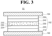
- FIG. 3 is a cross-sectional view illustrating an OLED according to a second embodiment of the present disclosure.
- the OLED D1 includes the first and second electrodes 160 and 164 facing each other and the organic emitting layer 162 therebetween.
- the organic emitting layer 162 includes a red EML 230.
- the organic light emitting display device 100 (of FIG. 2 ) includes the red, green and blue pixel regions, and the OLED D1 can be positioned in the red pixel region.
- the first electrode 160 is an anode for injecting the hole
- the second electrode 164 is a cathode for injecting the electron.
- One of the first and second electrodes 160 and 164 is a reflective electrode
- the other one of the first and second electrodes 160 and 164 is a transparent (semitransparent) electrode.
- the first electrode 160 can include a transparent conductive material, e.g., ITO or IZO
- the second electrode 164 can include one of Al, Mg, Ag, AlMg and MgAg.
- the organic emitting layer 162 can further include at least one of the HTL 220 under the red EML 230 and the ETL 240 on or over the red EML 230. Namely, the HTL 220 is disposed between the red EML 230 and the first electrode 160, and the ETL 240 is disposed between the red EML 230 and the second electrode 164.
- the organic emitting layer 162 can further include at least one of the HIL 210 under the HTL 220 and the EIL 250 on the ETL 240.
- the organic emitting layer 162 can further include at least one of the EBL between the HTL 220 and the red EML 230 and the HBL between the ETL 240 and the red EML 230.
- the red EML 230 can constitute an emitting part, or the red EML 230 and at least one of the HIL 210, the HTL 220, the EBL, the HBL, the ETL 240 and the EIL 250 can constitute the emitting part.
- the red EML 230 includes a first compound 232 being the red dopant, a second compound 234 being the p-type host, e.g., a first host, and a third compound 236 being the n-type host, e.g., a second host.
- the red EML can have a thickness of 100 to 400 ⁇ , e.g., 200 to 400 ⁇ .
- each of the second and third compounds 234 and 236 can have a weight % being greater than the first compound 232.
- the first compound 232 can have a weight % of 1 to 20, e.g., 5 to 15.
- a ratio of the weight % between the second compound 234 and the third compound 236 can be 1:3 to 3:1.
- the second and third compounds 234 and 236 can have the same weight %.
- the first compound 232 is represented by Formula 1-1.
- the first compound 232 is an organometallic compound and has a rigid chemical conformation so that it can enhance luminous efficiency and luminous lifespan of the OLED D1.
- unsubstituted means that the specified group bears no substituents, and hydrogen is linked.
- hydrogen comprises protium, deuterium and tritium without specific disclosure.
- substituent in the term "substituted” comprises, but is not limited to, unsubstituted or halogen-substituted C1-C20 alkyl, unsubstituted or halogen-substituted C1-C20 alkoxy, halogen, cyano, -CF3, a hydroxyl group, a carboxylic group, a carbonyl group, an amino group, a C1-C10 alkyl amino group, a C6-C30 aryl amino group, a C3-C30 hetero aryl amino group, a C6-C30 aryl group, a C3-C30 hetero aryl group, a nitro group, a hydrazyl group, a sulfonate group, a C1-C20 alkyl silyl group, a C1-C20 alkoxy silyl group, a C3-C20 cycloalkyl silyl group, a C6-
- alkyl refers to a branched or unbranched saturated hydrocarbon group of 1 to 20 carbon atoms, such as methyl, ethyl, n-propyl, isopropyl, n-butyl, isobutyl, s-butyl, t-butyl, n-pentyl, isopentyl, s-pentyl, neopentyl, hexyl, heptyl, octyl, nonyl, decyl, dodecyl, tetradecyl, hexadecyl, and the like.
- alkenyl is a hydrocarbon group of 2 to 20 carbon atoms containing at least one carbon-carbon double bond.
- the alkenyl group can be substituted with one or more substituents.
- alicyclic or "cycloalkyl” refers to non-aromatic carboncontaining ring composed of at least three carbon atoms.
- alicyclic groups include, but are not limited to, cyclopropyl, cyclobutyl, cyclopentyl, cyclohexyl, norbornyl, and the like.
- the alicyclic group can be substituted with one or more substituents.
- alkoxy refers to a branched or unbranched alkyl bonded through an ether linkage represented by the formula -O(-alkyl) where alkyl is defined herein.
- alkoxy include methoxy, ethoxy, n-propoxy, isopropoxy, butoxy, and tert-butoxy, and the like.
- alkyl amino refers to a group represented by the formula - NH(-alkyl) or -N(-alkyl) 2 where alkyl is defined herein.
- alkyl amino represented by the formula -NH(-alkyl) include, but not limited to, methylamino group, ethylamino group, propylamino group, isopropylamino group, butylamino group, isobutylamino group, (sec-butyl)amino group, (tert-butyl)amino group, pentylamino group, isopentylamino group, (tert-pentyl)amino group, hexylamino group, and the like.
- alkyl amino represented by the formula -N(-alkyl) 2 include, but not limited to, dimethylamino group, diethylamino group, dipropylamino group, diisopropylamino group, dibutylamino group, diisobutylamino group, di(sec-butyl)amino group, di(tert-butyl)amino group, dipentylamino group, diisopentylamino group, di(tert-pentyl)amino group, dihexylamino group, N-ethyl-N-methylamino group, N-methyl-N-propylamino group, N ethyl-N-propylamino group and the like.
- aromatic or aryl
- aryl is well known in the art.
- the term includes monocyclic rings linked covalently or fused-ring polycyclic groups.
- An aromatic group can be unsubstituted or substituted.
- aromatic or aryl include phenyl, 1-naphthyl, 2-naphthyl, 4-biphenyl, anthracenyl, and phenanthracenyl and the like. Substituents for each of the above noted aryl ring systems are acceptable substituents are defined herein.
- alkyl silyl group refers to any linear or branched, saturated or unsaturated acyclic or acyclic alkyl, and the alkyl has 1 to 20 carbon atoms.
- alkyl silyl group include a trimethylsilyl group, a trimethylsilyl group, a t-butyldimethylsilyl group, a vinyldimethylsilyl group, a propyldimethylsilyl group, a triphenylsilyl group, a diphenylsilyl group, and a phenylsilyl group.
- halogen refers to fluorine, chlorine, bromine or iodine atom.
- hetero in such as "a hetero aromatic ring", “a hetero cycloalkylene group”, “a hetero arylene group”, “a hetero aryl alkylene group”, “a hetero aryl oxylene group”, “a hetero cycloalkyl group”, “a hetero aryl group”, “a hetero aryl alkyl group”, “a hetero aryloxyl group”, “a hetero aryl amino group” and “a hetero aryl silyl group” means that at least one carbon atom, for example 1-5 carbons atoms, constituting an aromatic ring or an alicyclic ring is substituted with at least one hetero atom selected from the group consisting of N, O, S, Si, Se, P, B and combination thereof.
- hetero aromatic or “hetero aryl” refers to a heterocycle including hetero atoms selected from N, O and S in a ring where the ring system is an aromatic ring.
- the term includes monocyclic rings linked covalently or fused-ring polycyclic groups.
- a hetero aromatic group can be unsubstituted or substituted.
- hetero aromatic or hetero aryl examples include pyridyl, pyrrolyl, pyrazinyl, pyrimidinyl, thienyl (alternatively referred to as thiophenyl), thiazolyl, furanyl, imidazolyl, pyrazolyl, triazolyl, tetrazolyl, oxazolyl, oxadiazolyl, and thiadiazolyl.
- hetero aryl oxy refers to a group represented by the formula -O-(hetero aryl) where hetero aryl is defined herein.
- each of R and R 1 to R 3 in Formula 1-1 is independently a C 6 -C 30 aromatic group
- each of R and R 1 to R 3 can be independently selected from the group consisting of, but is not limited to, a C 6 -C 30 aryl group, a C 7 -C 30 aryl alkyl group, a C 6 -C 30 aryl oxy group and a C 6 -C 30 aryl amino group.
- each of R and R 1 to R 3 can be independently selected from the group consisting of, but is not limited to, an unfused or fused aryl group such as phenyl, biphenyl, terphenyl, naphthyl, anthracenyl, pentalenyl, indenyl, indenoindenyl, heptalenyl, biphenylenyl, indacenyl, phenalenyl, phenanthrenyl, benzophenanthrenyl, dibenzo-phenanthrenyl, azulenyl, pyrenyl, fluoranthenyl, triphenylenyl, chrysenyl, tetraphenylenyl, tetracenyl, pleiadenyl, picenyl, pentaphenylenyl, pentaceny
- each of R and R 1 to R 3 in Formula 1 is independently a C 3 -C 30 hetero aromatic group
- each of R and R 1 to R 3 can be independently selected from the group consisting of, but is not limited to, a C 3 -C 30 hetero aryl group, a C 4 -C 30 hetero aryl alkyl group, a C 3 -C 30 hetero aryl oxy group and a C 3 -C 30 hetero aryl amino group.
- each of R and R 1 to R 3 can be independently selected from the group consisting of, but is not limited to, an unfused or fused hetero aryl group such as pyrrolyl, pyridinyl, pyrimidinyl, pyrazinyl, pyridazinyl, triazinyl, tetrazinyl, imidazolyl, pyrazolyl, indolyl, iso-indolyl, indazolyl, indolizinyl, pyrrolizinyl, carbazolyl, benzo-carbazolyl, dibenzo-carbazolyl, indolo-carbazolyl, indeno-carbazolyl, benzo-furo-carbazolyl, benzo-thieno-carbazolyl, carbolinyl, quinolinyl, iso-quinol
- an unfused or fused hetero aryl group such as pyrrolyl, pyridinyl,
- each of the aromatic group or the hetero aromatic group of R and R 1 to R 3 can consist of one to three aromatic or hetero aromatic rings.
- the number of the aromatic or hetero aromatic rings of R and R 1 to R 3 is more than three, conjugated structure in the first compound 232 becomes too long, thus, the first compound 232 can have too narrow energy bandgap.
- each of the aryl group or the hetero aryl group of R and R 1 to R 3 can be independently selected from the group consisting of, but is not limited to, phenyl, biphenyl, naphthyl, anthracenyl, pyrrolyl, triazinyl, imidazolyl, pyrazolyl, pyridinyl, pyrazinyl, pyrimidinyl, pyridazinyl, furanyl, benzo-furanyl, dibenzo-furanyl, thiophenyl, benzo-thiophenyl, dibenzo-thiophenyl, carbazolyl, acridinyl, carbolinyl, phenazinyl, phenoxazinyl and phenothiazinyl.
- two adjacent R 1 , and/or R 2 and R 3 can form an unsubstituted or substituted C 3 -C 30 alicyclic ring (e.g., a C 5 -C 10 alicyclic ring), an unsubstituted or substituted C 3 -C 30 hetero alicyclic ring (e.g., a C 3 -C 10 hetero alicyclic ring), an unsubstituted or substituted C 6 -C 30 aromatic ring (e.g., a C 6 -C 20 aromatic ring) or an unsubstituted or substituted C 3 -C 30 hetero aromatic ring (e.g., a C 3 -C 20 hetero aromatic ring).
- C 3 -C 30 alicyclic ring e.g., a C 5 -C 10 alicyclic ring
- an unsubstituted or substituted C 3 -C 30 hetero alicyclic ring e.g., a C 3 -C 10
- the alicyclic ring, the hetero alicyclic ring, the aromatic ring and the hetero aromatic ring formed by: two adjacent R 1 ; or R 2 and R 3 are not limited to specific rings.
- the aromatic ring or the hetero aromatic ring formed by those groups can be independently selected from the group consisting of, but is not limited to, a benzene ring, a pyridine ring, an indole ring, a pyran ring, a fluorene ring unsubstituted or substituted with at least one C 1 -C 10 alkyl group.
- the first compound 232 being the organometallic compound having the structure of Formula 1-1 has a ligand with fused with multiple aromatic and/or hetero aromatic rings, thus it has narrow full-width at half maximum (FWHM) in photoluminescence spectrum. Particularly, since the first compound 232 has a rigid chemical conformation, its conformation is not rotated in the luminous process so that it can maintain good luminous lifespan. In addition, since the first compound 232 has specific ranges of photoluminescence emissions, the color purity of the light emitted from the first compound 232 can be improved.
- FWHM full-width at half maximum
- the first compound 232 can be a heteropletic metal complex including two different bidentate ligands coordinated to the central metal atom. (n is a positive integer in Formula 1-1)
- the photoluminescence color purity and emission colors of the first compound 232 can be controlled with ease by combining two different bidentate ligands.
- the first compound 232 having the structure of Formula 1-1 can emit yellow to red colors and can improve luminous efficiency of an organic light emitting diode.
- the first compound 232 can have the ring (a) with X 3 -X 5 , Y 1 and A to be represented by Formula 1-2.
- each of X 21 to X 27 is independently CR 1 or N;
- M can be iridium (Ir), palladium (Pd) or platinum (Pt).
- X 31 to X 38 can beCR 1 .
- R 1 can be selected from the group consisting of hydrogen, protium, deuterium and a C 1 -C 20 alkyl group unsubstituted or substituted with deuterium, or optionally, two of R 1 s of X 31 to X 33 can form a C 6 -C 30 aromatic ring unsubstituted or substituted with a C 1 -C 20 alkyl group.
- Y 4 can be CR 2 R 3 , N a or O.
- Each of R 2 and R 3 can be independently selected from the group consisting of hydrogen, protium, deuterium, a C 1 -C 20 alkyl group unsubstituted or substituted with deuterium and a C 6 -C 30 aromatic group (aryl group).
- one of m and n can be 1, and the other one of m and n can be 2.
- X 25 and X 26 are connected to each other to form an aromatic ring or a hetero aromatic ring so that the first compound 232 can be represented by Formula 1-4.
- X 26 and X 27 are connected to each other to form an aromatic ring or a hetero aromatic ring so that the first compound 232 can be represented by Formula 1-5.
- each of X 41 to X 45 is independently CR 1 or N; each of M, R, m, n and R 1 to R 3 is same as defined in Formula 1-1; and X 21 to X 24 and Y 3 is same as defined in Formula 1-2;
- each of X 51 to X 55 is independently CR 1 or N; M, m, n, R 1 to R 3 is same as defined in Formula 1-1; and each of X 34 to X 38 and Y 4 is same as defined in Formula 1-3.
- M can be iridium (Ir), palladium (Pd) or platinum (Pt).
- One of X 34 to X 38 and X 51 to X 55 can be N, and the rest of X 34 to X 38 and X 51 to X 55 can be CR 1 .
- Y 4 can be CR 2 R 3 , N a , O or S.
- R 1 can be selected from the group consisting of hydrogen, protium, deuterium, a C 1 -C 20 alkyl group unsubstituted or substituted with deuterium, a C 1 -C 20 alkyl silyl group, a C 6 -C 30 aromatic group (aryl group) or a C 3 -C 30 hetero aromatic group (hetero aryl group).
- Each of R 2 and R 3 can be independently selected from the group consisting of hydrogen, protium, deuterium, a C 1 -C 20 alkyl group unsubstituted or substituted with deuterium, a C 3 -C 30 alicyclic group, a C 3 -C 30 hetero alicyclic group, a C 6 -C 30 aromatic group (aryl group) or a C 3 -C 30 hetero aromatic group (hetero aryl group), or optionally, two adjacent R 1 , and/or R 2 and R 3 can form a C 3 -C 30 alicyclic ring, a C 3 -C 30 hetero alicyclic ring, a C 6 -C 30 aromatic ring or a C 3 -C 30 hetero aromatic ring.
- the auxiliary ligand can be a bidentate ligand wherein Z 1 and Z 2 are independently selected from the group consisting of an oxygen atom, a nitrogen atom, and a phosphorus atom.
- the bidentate ligand can be acetylacetonate-containing ligand, or N,N'- or N,O-bidentate anionic ligand.
- the center coordination metal can be iridium and the auxiliary ligand can be an acetylacetonate-containing ligand.
- M can be iridium, one of Z 1 and Z 2 can be an oxygen atom, and the other one of Z 1 and Z 2 can be a nitrogen atom.
- the first compound 232 can be represented by one of Formulas 1-12 to 1-15.
- M can be iridium, Z 1 and Z 2 can be a nitrogen atom.
- the first compound 232 can be represented by one of Formulas 1-16 to 1-23.
- the first compound 232 represented by Formula 1-8 can be one of the compounds in Formula 1-24.
- the first compound 232 represented by Formula 1-9 can be one of the compounds in Formula 1-25.
- the first compound 232 represented by Formula 1-10 can be one of the compounds in Formula 1-26.
- the first compound 232 can be one of the compounds in Formula 1-27.
- the first compound 232 can be one of the compounds in Formula 1-28.
- the first compound 232 can be one of the compounds in Formula 1-29.
- the compound D-1 (2-chloro-5-isopropylquinoline, 10 g, 48.62 mmol), the compound H-1 (ethyl 8-(4,4,5,5-tetramethyl-1,3,2-dioxanborolan-2-yl)naphthalene-1-caroboylate, 17.45 g, 53.48 mmol), Pd(OAc) 2 (0.5 g, 2.43 mmol), PPh 3 (chloro(tripphenylphosphine)[2-(2'-amino-1,1'-biphenyl)]palladium(II), 2.6 g, 9.72 mmol), K 2 CO 3 (20.2 g, 145.86 mmol), 1,4-dioxane (100 mL) and water (100 mL) were put into a reaction vessel, and then the solution was stirred at 100°C for 12 hours.
- the compound I-1 (ethyl 8-(5-isopropylquinolin-2-yl)naphthalene-1-carboxylate, 13.5 g, 36.6 mmol) and THF (100 mL) were put into a reaction vessel and then CH 3 MgBr (21.8 g, 182.70 mmol) was added dropwise into the reaction vessel at 0°C.
- CH 3 MgBr (21.8 g, 182.70 mmol) was added dropwise into the reaction vessel at 0°C.
- the solution was raised to room temperature, the reaction was complete after 12 hours, was extracted with ethyl acetate, water in the organic layer was removed with MgSO 4 , and then the solution was filtered and placed under reduced pressure to remove the solvent.
- the compound J-1 (2-(1-(5-isopropylquinolin-2-yl)naphthalene-8-yl)propan-2-ol, 20 g, 56.26 mmol) and a mixed aqueous solution (200 mL) of acetic acid and sulfuric acid were put into a reaction vessel, and then the solution was refluxed for 16 hours. After the reaction was complete, the solution was cooled to room temperature, and then the reactants were added dropwise into sodium hydroxide aqueous solution with ice. The organic layer was extracted with dichloromethane and water was removed with MgSO 4 .
- the compound K-1 (10.25 g, 30.37 mmol), 2-ethoxyethanol (200 mL) and distilled water (50 mL) were put into a reaction vessel, the solution was bubbled with nitrogen for 1 hour, IrCl 3 ⁇ H 2 O (4.4 g, 13.81 mmol) was added into the reaction vessel, and then the solution was refluxed for 2 days. After the reaction was complete, the solution was cooled to room temperature, and then the obtained solid was filtered. The solid was washed with hexane and water and dried to give the compound L-1 (4.0 g, yield: 32%).
- the compound C-2 (ethyl 3-6-(isopropylisoqunolin-1-yl)-naphthoate (14.4 g, yield: 80%) was obtained by repeating the synthesis process of the compound I-1 except that the compound A-2 (1-chloro-6-isopropylisoquinoline, 10 g, 48.62 mmol) and compound B-2 (ethyl 3-(4,4,5,5-tetramethyl-1,3,2-dioxanborolan-2-yl)-2-naphthoate (17.45 g, 53.50 mmol) were used instead of the compound D-1 (2-chloro-5-isopropylquinoline, 10 g, 48.62 mmol) and the compound H-1 (ethyl 8-(4,4,5,5-tetramethyl-1,3,2-dioxanborolan-2-yl)naphthalene-1-carboxlate, respectively.
- the compound D-2 (2-(3-(6-isopropylisoquinolin-1-yl)naphthalen-2-yl)propan-2-ol, 6.9 g, yield: 50%) was obtained by repeating the synthesis process of the compound J-1 except that the compound C-2 (ethyl 3-(6-isopropylisoquinolin-1-yl)-2-naphthoate, 14.4 g, 39.0 mmol) was used instead of the compound I-1 (ethyl 8-(5-isopropylquinolin-2-yl)naphthalene-1-caroboxylate, 13.5 g, 36.5 mmol).
- the compound E-2 (5-isopropyl-7,7-dimethyl-7H-benzo[de]naphtha[2,3-h]quinolone, 11.39 g, yield: 60%) was obtained by repeating the synthesis process of the Compound K-1 except that the compound D-2 (2-(3-(6-isopropylisoquinolin-1-yl)naphthalen-2-yl)propan-2-ol, 20 g, 56.26 mmol) was used instead of the compound J-1 (2-(1-(5-isopropylquinolin-2-yl)naphthalene-8-yl)propan-2-ol, 20 g, 56.26 mmol).
- the compound F-2 (4.7 g, yield: 34%) was obtained by repeating the synthesis process of the Compound L-1 except that the compound E-2 (11.39 g, 33.76 mmol) was used instead of the compound K-1 (10.25 g, 30.37 mmol).
- the compound 2 (3.2 g, yield: 57%) was obtained by repeating the synthesis process of compound 369 except that the Compound F-2 (4.7 g, 2.61 mmol) was used instead of the compound L-1 (4.0 g, 2.21 mmol). MS (m / z): 1076.48
- the compound C-3 (ethyl 8-6-(isopropylisoquinolin-3-yl)-naphthoate, 12.6 g, yield: 70%) was obtained by repeating the synthesis process of the compound I-1 except that the compound A-3 (3-chloro-6-isopropylisoquinoline, 10 g, 48.62 mmol) was used instead of the compound D-1 (2-chloro-5-isopropylquinoline, 10 g, 48.62 mmol). MS (m / z): 369.17
- the compound D-3 (2-(8-(6-isopropylisoquinolin-3-yl)naphthalen-1-yl)propan-2-ol, 7.3 g, yield: 60%) was obtained by repeating the synthesis process of the Compound J-1 except that the compound C-3 (ethyl 8-(6-isopropylisoquinolin-3-yl)naphthoate, 12.6 g, 34.0 mmol) was used instead of the compound I-1 (ethyl 8-(5-isopropylquinolin-2-yl)naphthalene-1-caroboxylate, 13.5 g, 36.5 mmol).
- the compound E-3 (2-isopropyl-13,13-dimethyl-13H-naphtho[1,8-bc]phenanthridine, 4.3 g, yield: 62%) was obtained by repeating the synthesis process of the Compound K-1 except that the compound D-3 (2-(8-(6-isopropylisoquinolin-3-yl)naphthalen-1-yl)propan-2-ol, 7.3 g, 20.4 mmol) was used instead of the compound J-1 (2-(1-(5-isopropylquinolin-2-yl)naphthalene-8-yl)propan-2-ol, 20 g, 56.26 mmol).
- the compound F-3 (1.9 g, yield: 37%) was obtained by repeating the synthesis process of the compound L-1 except that the compound E-3 (2-isopropyl-13,13-dimethyl-13H-naphtho[1,8-bc]phenanthridine, 4.3 g, 12.6 mmol) was used instead of the compound K-1 (10.25 g, 30.37 mmol).
- the compound 501 (1.4 g, yield: 60%) was obtained by repeating the synthesis process of compound 369 except that the compound F-3 (1.9 g, 1.07mmol ) was used instead of the compound L-1 (4.0 g, 2.21 mmol). MS (m / z): 1076.48
- the compound C-4 (12.2 g, yield: 68%) was obtained by repeating the synthesis process of the compound I-1 except that the compound A-4 (10 g, 48.62 mmol) and the compound B-4 (17.45 g, 53.48 mmol) were used instead of the compound D-1 (2-chloro-5-isopropylquinoline, 10 g, 48.62 mmol) and the compound H-1 (ethyl 8-(4,4,5,5-tetramethyl-1,3,2-dioxanborolan-2-yl)naphthalene-1-carboxlate (17.45 g, 53.48 mmol), respectively.
- the compound D-4 (6.8 g, yield: 58%) was obtained by repeating the synthesis process of the compound J-1 except that the compound C-4 (12.2 g, 33.02 mmol) was used instead of the compound I-1 (ethyl 8-(5-isopropylquinolin-2-yl)naphthalene-1-caroboxylate, 13.5 g, 36.5 mmol).
- the compound E-4 (4.1 g, yield: 63%) was obtained by repeating the synthesis process of the compound K-1 except that the compound D-4 (6.8 g, 19.15 mmol) was used instead of the compound J-1 (2-(1-(5-isopropylquinolin-2-yl)naphthalene-8-yl)propan-2-ol, 20 g, 56.26 mmol).
- the compound F-4 (2.1 g, yield: 42%) was obtained by repeating the synthesis process of the compound L-1 except that the compound E-4 (4.1 g, 12.15 mmol) was used instead of the compound K-1 (10.25 g, 30.37 mmol).
- the compound 182 (1.1 g, yield: 57%) was obtained by repeating the synthesis process of compound 369 except that the compound F-4 (2.1 g, 1.17mmol) was used instead of the compound L-1 (4.0 g, 2.21 mmol). MS (m / z): 1076.48
- the compound C-5 (11.8 g, yield: 78%) was obtained by repeating the synthesis process of the compound I-1 except that the compound A-5 (10 g, 48.62 mmol) and the compound B-5(14.4 g, 53.48 mmol) were used instead of the compound D-1 (2-chloro-5-isopropylquinoline, 10 g, 48.62 mmol) and the compound H-1 (ethyl 8-(4,4,5,5-tetramethyl-1,3,2-dioxanborolan-2-yl)naphthalene-1-carboxlate (17.45 g, 53.48 mmol), respectively.
- the compound F-5 (2.5 g, yield: 47%) was obtained by repeating the synthesis process of the compound L-1 except that the compound E-5 (4.6 g, 11.90 mmol) was used instead of the compound K-1 (10.25 g, 30.37 mmol).
- the compound 154 (1.4 g, yield: 46%) was obtained by repeating the synthesis process of compound 369 except that the compound F-5 (2.5 g, 1.25 mmol) was used instead of the compound L-1 (4.0 g, 2.21 mmol). MS (m / z): 1174.47
- the compound C-6 (11.4 g, yield: 75%) was obtained by repeating the synthesis process of the compound I-1 except that the compound A-6 (10 g, 48.62 mmol) and the compound B-6 (14.4 g, 53.48 mmol) were used instead of the compound D-1 (2-chloro-5-isopropylquinoline, 10 g, 48.62 mmol) and the compound H-1 (ethyl 8-(4,4,5,5-tetramethyl-1,3,2-dioxanborolan-2-yl)naphthalene-1-carboxlate (17.45 g, 53.48 mmol), respectively.
- the compound D-6 (6.8 g, yield: 58%) was obtained by repeating the synthesis process of the compound D5 except that the compound C-6 (11.4 g, 35.49 mmol) was used instead of the compound C-5 (11.8 g, 37.77 mmol).
- the compound E-6 (5.6 g, yield: 78%) was obtained by repeating the synthesis process of the compound E-5 except that the compound D-6 (5.8 g, 18.61 mmol) was used instead of the compound D-5 (4.6 g, 14.82 mmol).
- the compound F-6 (2.8 g, yield: 42%) was obtained by repeating the synthesis process of the compound L-1 except that the compound E-6 (5.6 g, 14.49 mmol) was used instead of the compound K-1 (10.25 g, 30.37 mmol).
- the compound 334 (2.0 g, yield: 61%) was obtained by repeating the synthesis process of compound 369 except that the compound F-6 (2.8 g, 1.38 mmol) was used instead of the compound L-1 (4.0 g, 2.21 mmol). MS (m / z): 1174.47
- the compound C-7 (9.0 g, yield: 50%) was obtained by repeating the synthesis process of the compound I-1 except that the compound A-7 (10 g, 48.62 mmol) and the compound B-7 (14.4 g, 53.48 mmol) were used instead of the compound D-1 (2-chloro-5-isopropylquinoline, 10 g, 48.62 mmol) and the compound H-1 (ethyl 8-(4,4,5,5-tetramethyl-1,3,2-dioxanborolan-2-yl)naphthalene-1-carboxlate (17.45 g, 53.48 mmol), respectively.
- the compound D-7 (7.4 g, yield: 55%) was obtained by repeating the synthesis process of the compoundD-5 except that the compound C-7 (9.0 g, 28.69 mmol) was used instead of the compound C-5 (11.8 g, 37.77 mmol).
- the compound E-7 (4.7 g, yield: 77%) was obtained by repeating the synthesis process of the compound E-5 except that the compound D-7 (4.9 g, 15.78 mmol) was used instead of the compound D-5 (4.6 g, 14.82 mmol).
- the compound F-7 (2.6 g, yield: 48%) was obtained by repeating the synthesis process of the compound L-1 except that the compound E-7 (4.7 g, 12.16 mmol) was used instead of the compound K-1 (10.25 g, 30.37 mmol).
- the compound 465 (2.0 g, yield: 64%) was obtained by repeating the synthesis process of compound 369 except that the compound F-7 (2.6 g, 1.33mmol) was used instead of the compound L-1 (4.0 g, 2.21 mmol). MS (m / z): 1174.47
- the compound C-8 (9.0 g, yield: 50%) was obtained by repeating the synthesis process of the compound I-1 except that the compound A-8 (10 g, 48.62 mmol) and the compound B-8 (14.4 g, 53.48 mmol) were used instead of the compound D-1 (2-chloro-5-isopropylquinoline, 10 g, 48.62 mmol) and the compound H-1 (ethyl 8-(4,4,5,5-tetramethyl-1,3,2-dioxanborolan-2-yl)naphthalene-1-carboxlate(17.45 g, 53.48 mmol), respectively.
- the compound D-8 (7.4 g, yield: 55%) was obtained by repeating the synthesis process of the compound D-5 except that the compound C-8 (10.0 g, 35.01 mmol) was used instead of the compound C-5 (11.8 g, 37.77 mmol).
- the compound E-8 (5.3 g, yield: 83%) was obtained by repeating the synthesis process of the compound E-5 except that the compound D-8 (5.1 g, 15.45 mmol) was used instead of the compound D-5 (4.6 g, 14.82 mmol). MS (m / z): 386.18
- the compound F-8 (2.4 g, yield: 39%) was obtained by repeating the synthesis process of the compound L-1 except that the compound E-8 (5.3 g, 13.66 mmol) was used instead of the compound K-1 (10.25 g, 30.37 mmol).
- the compound 582 (1.8 g, yield: 64%) was obtained by repeating the synthesis process of compound 369 except that the compound F-8 (2.4 g, 1.1 mmol) was used instead of the compound L-1 (4.0 g, 2.21 mmol). MS (m / z): 1174.47
- the compound C-9 (9.9 g, yield: 67%) was obtained by repeating the synthesis process of the compound I-1 except that the compound A-9 (10 g, 44.71 mmol) and the compound B-9 (13.3 g, 49.18 mmol) were used instead of the compound D-1 (2-chloro-5-isopropylquinoline, 10 g, 48.62 mmol) and the compound H-1 (ethyl 8-(4,4,5,5-tetramethyl-1,3,2-dioxanborolan-2-yl)naphthalene-1-carboxlate(17.45 g, 53.48 mmol), respectively.
- the compound E-9 (3.1 g, yield: 50%) was obtained by repeating the synthesis process of the compound L-1 except that the compound D-9 (4.9 g, 15.83 mmol) was used instead of the compound K-1 (10.25 g, 30.37 mmol).
- the compound 168 (2.0 g, yield: 54%) was obtained by repeating the synthesis process of compound 369 except that the compound E-9 (3.1 g, 1.80 mmol) was used instead of the Compound L-1 (4.0 g, 2.21 mmol). MS (m / z): 1024.38
- the compound C-10 (9.0 g, yield: 64%) was obtained by repeating the synthesis process of the compound I-1 except that the compound A-10 (10 g, 44.71 mmol) and the compound B-10 (13.3 g, 49.18 mmol) were used instead of the compound D-1 (2-chloro-5-isopropylquinoline, 10 g, 48.62 mmol) and the compound H-1 (ethyl 8-(4,4,5,5-tetramethyl-1,3,2-dioxanborolan-2-yl)naphthalene-1-carboxlate(17.45 g, 53.48 mmol), respectively.
- the compound D-10 (5.0 g, yield: 55%) was obtained by repeating the synthesis process of the compound D-9 except that the compound C-10 (9.6 g, 29.06 mmol) was used instead of the compound C-9 (9.9 g, 28.88 mmol).
- the compound E-10 (3.5 g, yield: 57%) was obtained by repeating the synthesis process of the compound L-1 except that the compound D-10 (5.0 g, 15.98 mmol) was used instead of the compound K-1 (10.25 g, 30.37 mmol).
- the compound 348 (1.8 g, yield: 43%) was obtained by repeating the synthesis process of compound 369 except that the compound E-10 (3.5 g, 2.07 mmol) was used instead of the compound L-1 (4.0 g, 2.21 mmol). MS (m / z): 1024.38
- the compound C-11 (7.9 g, yield: 53%) was obtained by repeating the synthesis process of the compound I-1 except that the compound A-11 (10 g, 44.71 mmol) and the compound B-11 (13.3 g, 49.18 mmol) were used instead of the Compound D-1 (2-chloro-5-isopropylquinoline, 10 g, 48.62 mmol) and the compound H-1 (ethyl 8-(4,4,5,5-tetramethyl-1,3,2-dioxanborolan-2-yl)naphthalene-1-carboxlate (17.45 g, 53.48 mmol), respectively.
- the compound D-11 (3.8 g, yield: 51%) was obtained by repeating the synthesis process of the compound D-9 except that the compound C-11 (7.9 g, 23.07 mmol) was used instead of the compound C-9 (9.9 g, 28.88 mmol).
- the compound E-11 (3.0 g, yield: 63%) was obtained by repeating the synthesis process of the compound L-1 except that the compound D-11 (3.8 g, 12.20 mmol) was used instead of the compound K-1 (10.25 g, 30.37 mmol).
- the compound 483 (1.6 g, yield: 44%) was obtained by repeating the synthesis process of compound 369 except that the compound E-11 (3.0 g, 1.75 mmol) was used instead of the compound L-1 (4.0 g, 2.21 mmol). MS (m / z): 1024.38
- the compound C-12 (9.8 g, yield: 66%) was obtained by repeating the synthesis process of the compound I-1 except that the compound A-12 (10 g, 44.71 mmol) and the compound B-12 (13.3 g, 49.18 mmol) were used instead of the compound D-1 (2-chloro-5-isopropylquinoline, 10 g, 48.62 mmol) and the compound H-1 (ethyl 8-(4,4,5,5-tetramethyl-1,3,2-dioxanborolan-2-yl)naphthalene-1-carboxlate(17.45 g, 53.48 mmol), respectively.
- the compound D-12 (5.0 g, yield: 54%) was obtained by repeating the synthesis process of the compound D-9 except that the compound C-12 (9.8 g, 29.51 mmol) was used instead of the compound C-9 (9.9 g, 28.88 mmol).
- the compound E-12 (3.4 g, yield: 55%) was obtained by repeating the synthesis process of the compound L-1 except that the compound D-12 (5.0 g, 15.93 mmol) was used instead of the compound K-1 (10.25 g, 30.37 mmol).
- the compound A-1 (1-chloro-6-isobutylisoquinoline, 10g, 45.51mmol), ethyl 3-(4,4,5,5-tetramethyl-1,3,2-dioxaborolan-2-yl)-2-naphthoate (16.3g, 50.06mmol), Pd(OAc) 2 (0.51g, 2.28mmol), PPh 3 (2.39g, 0.91mmol), K 2 CO 3 (18.9g, 136.53mmol), 1-4-dioxane (100mL) and water (100mL) were stirred at 100°C for 12 hours.
- the compound C-1 (2-(3-(6-isobutylisoquinolin-1-yl)naphthalen-2-yl)propan-2-ol, 10g, 27.06mmol) was added to a mixed aqueous solution of acetic acid and sulfuric acid (200mL), and the mixture was reflux and stirred for 16 hours. After completion of the reaction, the temperature was lowered to room temperature, and the reactant was slowly added to the sodium hydroxide aqueous solution. After extracting the organic layer using dichloromethane and removing water using MgSO 4 , the organic solvent was removed under reduced pressure. The mixture was recrystallized using toluene and ethanol to obtain the compound D-1 (5 g, 14.22 mmol) in a yellow solid state. (yield: 53%)
- the compound A-2 (1-chloro-6-isobutylisoquinoline, 10g, 45.51mmol), ethyl 2-(4,4,5,5-tetramethyl-1,3,2-dioxaborolan-2-yl)-1-naphthoate (16.3g, 50.06mmol), Pd(OAc) 2 (0.51g, 2.28mmol), PPh 3 (2.39g, 0.91mmol), K 2 CO 3 (18.9g, 136.53mmol), 1-4-dioxane (100mL) and water (100mL) were stirred at 100°C for 12 hours.
- the compound C-2 (2-(2-(6-isobutylisoquinolin-1-yl)naphthalen-1-yl)propan-2-ol, 10g, 27.06mmol) was added to a mixed aqueous solution of acetic acid and sulfuric acid (200mL), and the mixture was reflux and stirred for 16 hours. After completion of the reaction, the temperature was lowered to room temperature, and the reactant was slowly added to the sodium hydroxide aqueous solution. After extracting the organic layer using dichloromethane and removing water using MgSO 4 , the organic solvent was removed under reduced pressure. The mixture was recrystallized using toluene and ethanol to obtain the compound D-2 (4g, 11.38mmol) in a yellow solid state. (yield:42%)
- the compound A-3 (5-bromoquinoline, 50g, 240.33mmol), isobutylboronic acid (49g, 480.65mmol), Pd 2 (dba) 3 (6.6g, 3 mol%), Sphos (2-dicyclohexylphosphino-2',6'-dimethoxybiphenyl, 9.9g, 24.03mmol), potassium phosphate monohydrate (276.71g, 1.2mol) and toluene(1000mL) were stirred at 120°C for 12 hours. After completion of the reaction, the temperature was lowered, and the mixture was extracted with ethyl acetate. After the solvent was removed, the mixture was wet-purified using ethyl acetate and hexane to obtain the compound B-3 (35g, 188.92mmol). (yield: 79%)
- the compound C-4 (20g, 54.12mmol) was added to a mixed aqueous solution of acetic acid and sulfuric acid (200mL), and the mixture was reflux for 16 hours. After completion of the reaction, a cold sodium hydroxide aqueous solution was slowly added into the mixture. The mixture was worked-up using dichloromethane and MgSO 4 . The mixture was recrystallized using toluene and ethanol to obtain the compound D-4 (10g, 28.45mmol) in a yellow solid state. (yield: 53%)
- Synthesis Example 17 Synthesis of compound RD17 (compound 610 in Formula 1-29)
- the compound A-19 (3g, 1.62mmol) and THT (100ml) were added in a reaction vessel, and the compound F-1 (0.8g, 3.56mmol) dissolved in THF was slowly added. The mixture was stirred at room temperature for 8 hours. The mixture was extracted using toluene, the solvent was removed, and diethyl ether was added to obtain a solid. The obtained solid was purified to obtain the compound RD19 with high purity (1.1g, 1.01mmol).
- the compound A-20 (3g, 1.62mmol) and THT (100ml) were added in a reaction vessel, and the compound F-2 (0.8g, 3.56mmol) dissolved in THF was slowly added. The mixture was stirred at room temperature for 8 hours. The mixture was extracted using toluene, the solvent was removed, and diethyl ether was added to obtain a solid. The obtained solid was purified to obtain the compound RD20 with high purity (0.9g, 0.80mmol).
- the compound A-23 (3g, 1.62mmol) and THT (100ml) were added in a reaction vessel, and the compound F-1 (0.8g, 3.56mmol) dissolved in THF was slowly added. The mixture was stirred at room temperature for 8 hours. The mixture was extracted using toluene, the solvent was removed, and diethyl ether was added to obtain a solid. The obtained solid was purified to obtain the compound RD23 with high purity (2.5g, 2.29mmol).
- the compound A-24 (3g, 1.62mmol) and THT (100ml) were added in a reaction vessel, and the compound F-2 (0.8g, 3.56mmol) dissolved in THF was slowly added. The mixture was stirred at room temperature for 8 hours. The mixture was extracted using toluene, the solvent was removed, and diethyl ether was added to obtain a solid. The obtained solid was purified to obtain the compound RD24 with high purity (2.2g, 1.95mmol).
- Synthesis Example 25 Synthesis of compound RD25 (compound 618 in Formula 1-29)
- Synthesis Example 26 Synthesis of compound RD26 (compound 619 in Formula 1-29)
- Synthesis Example 27 Synthesis of compound RD27 (compound 620 in Formula 1-29)
- the compound A-27 (3g, 1.62mmol) and THT (100ml) were added in a reaction vessel, and the compound F-1 (0.8g, 3.56mmol) dissolved in THF was slowly added. The mixture was stirred at room temperature for 8 hours. The mixture was extracted using toluene, the solvent was removed, and diethyl ether was added to obtain a solid. The obtained solid was purified to obtain the compound RD27 with high purity (2.2g, 2.02mmol).
- Synthesis Example 28 Synthesis of compound RD28 (compound 621 in Formula 1-29)
- the compound A-28 (3g, 1.62mmol) and THT (100ml) were added in a reaction vessel, and the compound F-2 (0.8g, 3.56mmol) dissolved in THF was slowly added. The mixture was stirred at room temperature for 8 hours. The mixture was extracted using toluene, the solvent was removed, and diethyl ether was added to obtain a solid. The obtained solid was purified to obtain the compound RD28 with high purity (1.9g, 1.68mmol).
- the compound A-31 (3g, 1.62mmol) and THT (100ml) were added in a reaction vessel, and the compound F-1 (0.8g, 3.56mmol) dissolved in THF was slowly added. The mixture was stirred at room temperature for 8 hours. The mixture was extracted using toluene, the solvent was removed, and diethyl ether was added to obtain a solid. The obtained solid was purified to obtain the compound RD31 with high purity (2.0g, 1.84mmol).
- the compound A-32 (3g, 1.62mmol) and THT (100ml) were added in a reaction vessel, and the compound F-2 (0.8g, 3.56mmol) dissolved in THF was slowly added. The mixture was stirred at room temperature for 8 hours. The mixture was extracted using toluene, the solvent was removed, and diethyl ether was added to obtain a solid. The obtained solid was purified to obtain the compound RD32 with high purity (1.8g, 1.59mmol).
- the second compound 234 has an excellent hole-dominant property (characteristic) and is represented by Formula 2-1. wherein
- R 4 , R 5 and R 6 may be same or different.
- the C 6 -C 30 aryl group, the C 3 -C 30 heteroaryl group, the C 6 -C 30 arylene group and the C 3 -C 30 heteroarylene group may be substituted with a C 1 -C 10 alkyl group or a C 6 -C 30 aryl group.
- R 4 may be selected from an unsubstituted or substituted C 6 -C 30 aryl.
- L may be selected from an unsubstituted or substituted C 6 -C 30 arylene group, or a may be 0.
- R 4 may be an unsubstituted C 6 -C 30 aryl group, e.g., phenyl.
- Each of R 5 and R 6 may be independently selected from the group consisting of a substituted unsubstituted C 6 -C 30 aryl group, e.g., phenyl, naphthyl or biphenyl, a substituted C 6 -C 30 aryl group, e.g., 9,9-dimethylfluorenyl, and an unsubstituted C 3 -C 30 heteroaryl group, e.g., dibenzofuranyl or dibenzothiophenyl.
- L may be a substituted C 6 -C 30 arylene group, e.g., phenylene.
- one of X 12 and X 13 may be N, and the other one of X 12 and X 13 may be O, and each of R 4 , R 5 and R 6 may be an unsubstituted or substituted C 6 -C30 aryl group.
- R 4 may be phenyl.
- R 5 and R 6 may be different, R 5 may be phenyl or biphenyl, and R 6 may be independently selected from naphthyl, biphenyl and 9,9-dimethylfluorenyl.
- the second compound 234 can be one of the compounds in Formula 2-2.
- the third compound 236 has an excellent electron-dominant property (characteristic) and is represented by Formula 3-1. wherein
- each of R 7 and R 8 may be independently selected from an unsubstituted or substituted C 6 -C 30 aryl group.
- R 7 may be selected from phenyl, biphenyl, naphthyl and 9,9-dimethylfluorenyl
- R 8 may be selected from phenyl, naphthyl and biphenyl.
- Formula 3-1 a linking position (or a linking site) of a X-containing fused-ring to a benzocarbazole moiety (or a naphtho benzofuran moiety) can be specified. Namely, Formula 3-1 can be represented by Formula 3-2.
- Formula 3-1 a linking position between a X-containing fused-ring and a benzocarbazole moiety (or a naphtho benzofuran moiety) can be specified. Namely, Formula 3-1 can be represented by Formula 3-3.
- the third compound 236 can be one of the compounds in Formula 3-4.
- the HIL 210 is positioned between the first electrode 160 and the HTL 220.
- the HIL 210 can include at least one compound selected from the group consisting of 4,4',4"-tris(3-methylphenylamino)triphenylamine (MTDATA), 4,4',4"-tris(N,N-diphenyl-amino)triphenylamine(NATA), 4,4',4"-tris(N-(naphthalene-1-yl)-N-phenyl-amino)triphenylamine(1T-NATA), 4,4',4"-tris(N-(naphthalene-2-yl)-N-phenyl-amino)triphenylamine(2T-NATA), copper phthalocyanine (CuPc), tris(4-carbazoyl-9-yl-phenyl)amine (TCTA), N,N'-diphenyl-N,N'-bis(1-naphthyl)-1,1'
- the HTL 220 is positioned between the HIL 210 and the red EML 230.
- the HTL 220 can include at least one compound selected from the group consisting of N,N'-diphenyl-N,N'-bis(3-methylphenyl)-1,1'-biphenyl-4,4'-diamine(TPD),NPB(or NPD), 4,4'-bis(N-carbazolyl)-1,1'-biphenyl(CBP), poly[N,N'-bis(4-butylphenyl)-N,N'-bis(phenyl)-benzidine](poly-TPD), (poly[(9,9-dioctylfluorenyl-2,7-diyl)-co-(4,4'-(N-(4-sec-butylphenyl)diphenylamine))] (TFB), di-[4-(N,N-di-p-tolyl-phenyl]
- the ETL 240 is positioned between the red EML 230 and the second electrode 164 and includes at least one of an oxadiazole-containing compound, a triazole-containing compound, a phenanthroline-containing compound, a benzoxazole-containing compound, a benzothiazole-containing compound, a benzimidazole-containing compound, and a triazine-containing compound.
- the ETL 240 can include at least one compound selected from the group consisting of tris-(8-hydroxyquinoline aluminum (Alq 3 ),2-biphenyl-4-yl-5-(4-t-butylphenyl)-1,3,4-oxadiazole (PBD), spiro-PBD, lithium quinolate (Liq), 1,3,5-tris(N-phenylbenzimidazol-2-yl)benzene (TPBi), bis(2-methyl-8-quinolinolato-N1,O8)-(1,1'-biphenyl-4-olato)aluminum (BAlq), 4,7-diphenyl-1,10-phenanthroline (Bphen), 2,9-bis(naphthalene-2-yl)-4,7-diphenyl-1,10-phenanthroline(NBphen), 2,9-dimethyl-4,7-diphenyl-1,10-phenathroline(BCP), 3-(4-biphenyl
- the EIL 250 is positioned between the ETL 240 and the second electrode 164.
- the EIL 250 at least one of an alkali halide compound, such as LiF, CsF, NaF, or BaF 2 , and an organo-metallic compound, such as Liq, lithium benzoate, or sodium stearate, but it is not limited thereto.
- the EIL 250 can have a thickness of 1 to 20A, preferably 5 to 15A.
- the EBL which is positioned between the HTL 220 and the red EML 230 to block the electron transfer from the red EML 230 to the HTL 220, can include at least one compound selected from the group consisting of TCTA, tris[4-(diethylamino)phenyl]amine, N-(biphenyl-4-yl)-9,9-dimethyl-N-(4-(9-phenyl-9H-carbazol-3-yl)phenyl)-9H-fluoren-2-amine, TAPC, MTDATA, 1,3-bis(carbazol-9-yl)benzene (mCP), 3,3'-bis(N-carbazolyl)-1,1'-biphenyl (mCBP), CuPc,N,N'-bis[4-[bis(3-methylphenyl)amino]phenyl]-N,N'-diphenyl-[1,1'-biphenyl]-4,4'-diamine (DNTPD
- the HBL which is positioned between the ETL 240 and the red EML 230 to block the hole transfer from the red EML 230 to the ETL 240, can include the above material of the ETL 240.
- the material of the HBL has a HOMO energy level being lower than a material of the red EML 230 and can be at least one compound selected from the group consisting of BCP, BAlq, Alq3, PBD, spiro-PBD, Liq, bis-4,6-(3,5-di-3-pyridylphenyl)-2-methylpyrimidine (B3PYMPM), bis[2-(diphenylphosphino)phenyl]ether oxide(DPEPO), 9-(6-9H-carbazol-9-yl)pyridine-3-yl)-9H-3,9'-bicarbazole, and TSPO1, but it is not limited thereto.
- the OLED D1 is positioned in the red pixel region, and the red EML 230 of the OLED D1 includes the first compound 232, which is represented by Formula 1-1, being a dopant, the second compound 234, which is represented by Formula 2-1, being a first host or a p-type host and the third compound 236, which is represented by Formula 3-1, being a second host or an n-type host.
- the driving voltage is decreased, and the luminous efficiency and the luminous lifespan is increased.
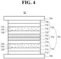
- FIG. 4 is a cross-sectional view illustrating an OLED according to a third embodiment of the present disclosure.
- the OLED D2 includes first and second electrodes 160 and 164 facing each other and the organic emitting layer 162 therebetween.
- the organic emitting layer 162 includes a first emitting part 710 including a first red EML 720 and a second emitting part 730 including a second red EML 740.
- the organic emitting layer 162 can further include a charge generation layer (CGL) 750 between the first and second emitting parts 710 and 730.
- CGL charge generation layer
- the first electrode 160 can include a transparent conductive material, e.g., ITO or IZO
- the second electrode 164 can include one of Al, Mg, Ag, AlMg and MgAg.
- the CGL 750 is positioned between the first and second emitting parts 710 and 730 so that the first emitting part 710, the CGL 750 and the second emitting part 730 are sequentially stacked on the first electrode 160. Namely, the first emitting part 710 is positioned between the first electrode 160 and the CGL 750, and the second emitting part 730 is positioned between the second electrode 164 and the CGL 750.
- the first emitting part 710 includes the first red EML 720.
- the first red EML 720 includes a first compound 722 as a red dopant (e.g., a red emitter), a second compound 724 as a p-type host (e.g., a first host) and a third compound 726 as an n-type host (e.g., a second host).
- the first compound 722 is represented by Formula 1-1
- the second compound 724 is represented by Formula 2-1
- the third compound 726 is represented by Formula 3-1.
- the first red EML 720 can have a thickness of 100 to 400 ⁇ , e.g., 200 to 400 ⁇ , but it is not limited thereto.
- each of the second and third compounds 724 and 726 can have a weight % being greater than the first compound 722.
- the first compound 722 can have a weight % of 1 to 20, e.g., 5 to 15.
- a ratio of the weight % between the second compound 724 and the third compound 726 can be 1:3 to 3:1.
- the second and third compounds 724 and 726 can have the same weight %.
- the first emitting part 710 can further include at least one of a first HTL 714 under the first red EML 720 and a first ETL 716 on or over the first red EML 720. Namely, the first HTL 714 is disposed between the first red EML 720 and the first electrode 160, and the first ETL 716 is disposed between the first red EML 720 and the CGL 750.
- the first emitting part 710 can further include an HIL 712 between the first electrode 160 and the first HTL 714.
- the second emitting part 730 includes the second red EML 740.
- the second red EML 740 includes a first compound 742, e.g., a fourth compound, as a red dopant (e.g., a red emitter), a second compound 744, e.g., a fifth compound, as a p-type host (e.g., a first host) and a third compound 746, e.g., a sixth compound, as an n-type host (e.g., a second host).
- the first compound 742 is represented by Formula 1-1
- the second compound 744 is represented by Formula 2-1
- the third compound 746 is represented by Formula 3-1.
- the second red EML 740 can have a thickness of 100 to 400 ⁇ , e.g., 200 to 400 ⁇ , but it is not limited thereto.
- each of the second and third compounds 744 and 746 can have a weight % being greater than the first compound 742.
- the first compound 742 can have a weight % of 1 to 20, e.g., 5 to 15.
- a ratio of the weight % between the second compound 744 and the third compound 746 can be 1:3 to 3:1.
- the second and third compounds 744 and 746 can have the same weight %.
- the first compound 742 in the second red EML 740 and the first compound 722 in the first red EML 720 can be same or different.
- the second compound 744 in the second red EML 740 and the second compound 724 in the first red EML 720 can be same or different.
- the third compound 746 in the second red EML 740 and the third compound 726 in the first red EML 720 can be same or different.
- the second emitting part 730 can further include at least one of a second HTL 732 under the second red EML 740 and a second ETL 734 on or over the second red EML 740.
- the second HTL 732 is disposed between the second red EML 740 and the CGL 750
- the second ETL 734 is disposed between the second red EML 740 and the second electrode 164.
- the second emitting part 730 can further include an EIL 736 between the second ETL 734 and the second electrode 164.
- the CGL 750 is positioned between the first and second emitting parts 710 and 730. Namely, the first and second emitting parts 710 and 730 are connected to each other through the CGL 750.
- the CGL 750 can be a P-N junction type CGL of an N-type CGL 752 and a P-type CGL 754.
- the N-type CGL 752 is positioned between the first ETL 716 and the second HTL 732, and the P-type CGL 754 is positioned between the N-type CGL 752 and the second HTL 732.
- At least one of the first and second red EMLs 720 and 740 includes a first compound, e.g., a red dopant, represented by Formula 1-1, a second compound, e.g., a p-type host, represented by Formula 2-1 and a third compound, e.g., an n-type host, represented by Formula 3-1.
- a first compound e.g., a red dopant, represented by Formula 1-1
- a second compound e.g., a p-type host, represented by Formula 2-1
- a third compound e.g., an n-type host
- FIG. 5 is a cross-sectional view illustrating an organic light emitting display device according to a fourth embodiment of the present disclosure.
- the organic light emitting display device 300 includes a first substrate 310, where a red pixel region RP, a green pixel region GP and a blue pixel region BP are defined, a second substrate 370 facing the first substrate 310, an OLED D, which is positioned between the first and second substrates 310 and 370 and providing white emission, and a color filter layer 380 between the OLED D and the second substrate 370.
- Each of the first and second substrates 310 and 370 can be a glass substrate or a flexible substrate.
- each of the first and second substrates 310 and 370 can be a polyimide (PI) substrate, a polyethersulfone (PES) substrate, a polyethylenenaphthalate (PEN) substrate, a polyethylene terephthalate (PET) substrate or a polycarbonate (PC) substrate.
- PI polyimide
- PES polyethersulfone
- PEN polyethylenenaphthalate
- PET polyethylene terephthalate
- PC polycarbonate
- a buffer layer 320 is formed on the substrate, and the TFT Tr corresponding to each of the red, green and blue pixel regions RP, GP and BP is formed on the buffer layer 320.
- the buffer layer 320 can be omitted.
- a semiconductor layer 322 is formed on the buffer layer 320.
- the semiconductor layer 322 can include an oxide semiconductor material or polycrystalline silicon.
- a gate insulating layer 324 is formed on the semiconductor layer 322.
- the gate insulating layer 324 can be formed of an inorganic insulating material such as silicon oxide or silicon nitride.
- a gate electrode 330 which is formed of a conductive material, e.g., metal, is formed on the gate insulating layer 324 to correspond to a center of the semiconductor layer 322.
- the interlayer insulating layer 332 can be formed of an inorganic insulating material, e.g., silicon oxide or silicon nitride, or an organic insulating material, e.g., benzocyclobutene or photo-acryl.
- the interlayer insulating layer 332 includes first and second contact holes 334 and 336 exposing both sides of the semiconductor layer 322.
- the first and second contact holes 334 and 336 are positioned at both sides of the gate electrode 330 to be spaced apart from the gate electrode 330.
- the source electrode 340 and the drain electrode 342 are spaced apart from each other with respect to the gate electrode 330 and respectively contact both sides of the semiconductor layer 322 through the first and second contact holes 334 and 336.
- the semiconductor layer 322, the gate electrode 330, the source electrode 340 and the drain electrode 342 constitute the TFT Tr.
- the TFT Tr serves as a driving element. Namely, the TFT Tr can correspond to the driving TFT Td (of FIG. 1 ).
- the gate line and the data line cross each other to define the pixel, and the switching TFT is formed to be connected to the gate and data lines.
- the switching TFT is connected to the TFT Tr as the driving element.
- the power line which can be formed to be parallel to and spaced apart from one of the gate and data lines, and the storage capacitor for maintaining the voltage of the gate electrode of the TFT Tr in one frame can be further formed.
- a planarization layer 350 which includes a drain contact hole 352 exposing the drain electrode 342 of the TFT Tr, is formed to cover the TFT Tr.
- a first electrode 360 which is connected to the drain electrode 342 of the TFT Tr through the drain contact hole 352, is separately formed in each pixel region and on the planarization layer 350.
- the first electrode 360 can be an anode and can be formed of a conductive material, e.g., a transparent conductive oxide (TCO), having a relatively high work function.
- the first electrode 360 can further include a reflection electrode or a reflection layer.
- the reflection electrode or the reflective layer can include Ag or aluminum-palladium-copper (APC).
- the first electrode 360 can have a structure of ITO/Ag/ITO or ITO/APC/ITO.
- a bank layer 366 is formed on the planarization layer 350 to cover an edge of the first electrode 360. Namely, the bank layer 366 is positioned at a boundary of the pixel and exposes a center of the first electrode 360 in the pixel. Since the OLED D emits the white light in the red, green and blue pixel regions RP, GP and BP, the organic emitting layer 362 can be formed as a common layer in the red, green and blue pixel regions RP, GP and BP without separation. The bank layer 366 can be formed to prevent a current leakage at an edge of the first electrode 360 and can be omitted.
- An organic emitting layer 362 is formed on the first electrode 360. As illustrated below, the organic emitting layer 362 includes at least two emitting parts, and each emitting part includes at least one EML. As a result, the OLED D emits the white light.
- At least one of the emitting parts includes a first compound, e.g., a red dopant, represented by Formula 1-1, a second compound, e.g., a p-type host or a first host, represented by Formula 2-1 and a third compound, e.g., an n-type host or a second host, represented by Formula 3-1 to emit the red light.
- a first compound e.g., a red dopant
- Formula 1-1 e.g., a red dopant
- a second compound e.g., a p-type host or a first host, represented by Formula 2-1
- a third compound e.g., an n-type host or a second host, represented by Formula 3-1 to emit the red light.
- a second electrode 364 is formed over the substrate 310 where the organic emitting layer 362 is formed.
- the second electrode 364 since the light emitted from the organic emitting layer 362 is incident to the color filter layer 380 through the second electrode 364, the second electrode 364 has a thin profile for transmitting the light.
- the first electrode 360, the organic emitting layer 362 and the second electrode 364 constitute the OLED D.
- the color filter layer 380 is positioned over the OLED D and includes a red color filter 382, a green color filter 384 and a blue color filter 386 respectively corresponding to the red, green and blue pixel regions RP, GP and BP.
- the red color filter 382 can include at least one of red dye and red pigment
- the green color filter 384 can include at least one of green dye and green pigment
- the blue color filter 386 can include at least one of blue dye and blue pigment.
- the color filter layer 380 can be attached to the OLED D by using an adhesive layer. Alternatively, the color filter layer 380 can be formed directly on the OLED D.
- An encapsulation film can be formed to prevent penetration of moisture into the OLED D.
- the encapsulation film can include a first inorganic insulating layer, an organic insulating layer and a second inorganic insulating layer sequentially stacked, but it is not limited thereto.
- the encapsulation film can be omitted.
- a polarization plate for reducing an ambient light reflection can be disposed over the top-emission type OLED D.
- the polarization plate can be a circular polarization plate.
- the first and second electrodes 360 and 364 are a reflection electrode and a transparent (or semi-transparent) electrode, respectively, and the color filter layer 380 is disposed over the OLED D.
- the color filter layer 380 can be disposed between the OLED D and the first substrate 310.
- a color conversion layer can be formed between the OLED D and the color filter layer 380.
- the color conversion layer can include a red color conversion layer, a green color conversion layer and a blue color conversion layer respectively corresponding to the red, green and blue pixel regions RP, GP and BP.
- the white light from the OLED D is converted into the red light, the green light and the blue light by the red, green and blue color conversion layer, respectively.
- the color conversion layer can include a quantum dot. Accordingly, the color purity of the organic light emitting display device 300 can be further improved.
- the color conversion layer can be included instead of the color filter layer 380.
- the OLED D in the red, green and blue pixel regions RP, GP and BP emits the white light, and the white light from the organic light emitting diode D passes through the red color filter 382, the green color filter 384 and the blue color filter 386.
- the red light, the green light and the blue light are provided from the red pixel region RP, the green pixel region GP and the blue pixel region BP, respectively.
- the OLED D emitting the white light is used for a display device.
- the OLED D can be formed on an entire surface of a substrate without at least one of the driving element and the color filter layer to be used for a lightening device.
- the display device and the lightening device each including the OLED D of the present disclosure can be referred to as an organic light emitting device.
- FIG. 6 is a cross-sectional view illustrating an OLED according to a fifth embodiment of the present disclosure.
- the organic emitting layer 362 includes a first emitting part 430 including a red EML 410, a second emitting part 440 including a first blue EML 450 and a third emitting part 460 including a second blue EML 470.
- the organic emitting layer 362 can further include a first CGL 480 between the first and second emitting parts 430 and 440 and a second CGL 490 between the first and third emitting part 430 and 460.
- the first emitting part 430 can further include a green EML 420.
- the first electrode 360 is an anode
- the second electrode 364 is a cathode.
- One of the first and second electrodes 360 and 364 can be a transparent (semitransparent) electrode, and the other one of the first and second electrodes 360 and 364 can be a reflective electrode.
- the second emitting part 440 is positioned between the first electrode 360 and the first emitting part 430, and the third emitting part 460 is positioned between the first emitting part 430 and the second electrode 364.
- the second emitting part 440 is positioned between the first electrode 360 and the first CGL 480, and the third emitting part 460 is positioned between the second CGL 490 and the second electrode 364.
- the second emitting part 440, the first CGL 480, the first emitting part 430, the second CGL 460 and the third emitting part 460 are sequentially stacked on the first electrode 360.
- the green EML 420 is positioned on the red EML 410.
- the first emitting part 430 can further include at least one of a first HTL 432 under the red EML 410 and a first ETL 434 over the red EML 410.
- the first emitting part 430 includes the green EML 420
- the first ETL 434 is positioned on the green EML 420.
- the second emitting part 440 can further include at least one of a second HTL 444 under the first blue EML 450 and a second ETL 448 on the first blue EML 450.
- the second emitting part 440 can further include an HIL 442 between the first electrode 360 and the first HTL 444.
- the second emitting part 440 can further include at least one of a first EBL between the second HTL 444 and the first blue EML 450 and a first HBL between the first blue EML 450 and the second ETL 448.
- the third emitting part 460 can further include at least one of a third HTL 462 under the second blue EML 470 and a third ETL 466 on the second blue EML 470.
- the third emitting part 460 can further include an EIL 468 between the second electrode 364 and the third ETL 466.
- the third emitting part 460 can further include at least one of a first EBL between the third HTL 462 and the second blue EML 470 and a first HBL between the second blue EML 470 and the third ETL 466.
- the HIL 442 can include at least one of MTDATA, NATA, 4,4',4"-tris(N-(naphthalene-1-yl)-N-phenyl-amino)triphenylamine 1T-NATA, 2T-NATA, CuPc, TCTA, NPB, HAT-CN, TDAPB, PEDOT/PSS and N-(biphenyl-4-yl)-9,9-dimethyl-N-(4-(9-phenyl-9H-carbazol-3-yl)phenyl)-9H-fluoren-2-amine.
- MTDATA NATA
- Each of the first to third HTLs 432, 444 and 464 can include at least one of TPD,NPB, CBP, poly-TPD, TFB, TAPC, DCDPA, N-(biphenyl-4-yl)-9,9-dimethyl-N-(4-(9-phenyl-9H-carbazol-3-yl)phenyl)-9H-fluoren-2-amine, N-(biphenyl-4-yl)-N-(4-(9-phenyl-9H-carbazol-3-yl)phenyl)biphenyl-4-amine, and the compound in Formula 4.
- Each of the first to third ETLs 434, 448 and 466 can include at least one of Alq3,PBD, spiro-PBD, Liq, TPBi, BAlq, Bphen, NBphen, BCP, TAZ, NTAZ, TpPyPB, TmPPPyTz, PFNBr, TPQ, and TSPO1.
- the EIL 468 can include at least one of an alkali halide compound, such as LiF, CsF, NaF, or BaF 2 , and an organo-metallic compound, such as Liq, lithium benzoate, or sodium stearate.
- an alkali halide compound such as LiF, CsF, NaF, or BaF 2
- an organo-metallic compound such as Liq, lithium benzoate, or sodium stearate.
- the first CGL 480 is positioned between the first and second emitting parts 430 and 440, and the second CGL 490 is positioned between the first and third emitting parts 430 and 460.
- the first and second emitting parts 430 and 440 is connected to each other by the first CGL 480
- the first and third emitting parts 430 and 460 is connected to each other by the second CGL 490.
- the first CGL 480 can be a P-N junction type CGL of an N-type CGL 482 and a P-type CGL 484
- the second CGL 490 can be a P-N junction type CGL of an N-type CGL 492 and a P-type CGL 494.
- the N-type CGL 482 is positioned between the first HTL 432 and the second ETL 448
- the P-type CGL 484 is positioned between the N-type CGL 482 and the first HTL 432.
- the N-type CGL 492 is positioned between the first ETL 434 and the third HTL 462, and the P-type CGL 494 is positioned between the N-type CGL 492 and the third HTL 462.
- Each of the N-type CGL 482 of the first CGL 480 and the N-type CGL 492 of the second CGL 490 can be an organic layer doped with an alkali metal, e.g., Li, Na, K or Cs, and/or an alkali earth metal, e.g., Mg, Sr, Ba or Ra.
- an alkali metal e.g., Li, Na, K or Cs
- an alkali earth metal e.g., Mg, Sr, Ba or Ra.
- each of the N-type CGL 482 of the first CGL 480 and the N-type CGL 492 of the second CGL 490 can include an organic material, e.g., 4,7-dipheny-1,10-phenanthroline(Bphen) or MTDATA, as a host, and the alkali metal and/or the alkali earth metal as a dopant can be doped with a weight % of about 0.01 to 30.
- an organic material e.g., 4,7-dipheny-1,10-phenanthroline(Bphen) or MTDATA
- Each of the P-type CGL 484 of the first CGL 480 and the P-type CGL 494 of the second CGL 490 can include at least one of an inorganic material, which is selected from the group consisting of tungsten oxide (WOx), molybdenum oxide (MoOx), beryllium oxide (Be2O3), vanadium oxide (V2O5) and their combination, and an organic material, which is selected from the group consisting of NPD, HAT-CN, F4TCNQ, TPD, N,N,N',N'-tetranaphthyl-benzidine (TNB), TCTA, N,N'-dioctyl-3,4,9,10-perylenedicarboximide (PTCDI-C8) and their combination.
- an inorganic material which is selected from the group consisting of tungsten oxide (WOx), molybdenum oxide (MoOx), beryllium oxide (Be2O3), vanadium oxide (V2O5) and
- the red EML 410 includes a first compound 412 as a red dopant (e.g., a red emitter), a second compound 414 as a p-type host (e.g., a first host) and a third compound 416 as an n-type host (e.g., a second host).
- the first compound 412 is represented by Formula 1-1
- the second compound 414 is represented by Formula 2-1
- the third compound 416 is represented by Formula 3-1.
- each of the second and third compounds 414 and 416 can have a weight % being greater than the first compound 412.
- the first compound 412 can have a weight % of 1 to 20, e.g., 5 to 15.
- a ratio of the weight % between the second compound 414 and the third compound 416 can be 1:3 to 3:1.
- the second and third compounds 414 and 416 can have the same weight %.
- the green EML 420 includes a green host and a green dopant.
- the green dopant can be one of a phosphorescent compound, a fluorescent compound and a delayed fluorescent compound.
- the host can be 4,4'-bis(carbazol-9-yl)biphenyl (CBP)
- the green dopant can be fac tris(2-phenylpyridine)iridium Ir(ppy)3 or tris(8-hydroxyquinolino)aluminum (Alq3).
- the first blue EML 450 in the second emitting part 440 includes a first blue host and a first blue dopant
- the second blue EML 470 in the third emitting part 460 includes a second blue host and a second blue dopant.
- each of the first and second blue hosts can be independently selected from the group consisting of mCP, 9-(3-(9H-carbazol-9-yl)phenyl)-9H-carbazole-3-carbonitrile (mCP-CN), mCBP, CBP-CN, 9-(3-(9H-Carbazol-9-yl)phenyl)-3-(diphenylphosphoryl)-9H-carbazole (mCPPO1) 3,5-Di(9H-carbazol-9-yl)biphenyl (Ph-mCP), TSPO1, 9-(3'-(9H-carbazol-9-yl)-[1,1'-biphenyl]-3-yl)-9H-pyrido[2,3-b]indole (CzBPCb), bis(2-methylphenyl)diphenylsilane (UGH-1), 1,4-bis(triphenylsilyl)benzene (UGH-2), 1,3-bis(trimeth
- each of the first and second blue dopants can be independently selected from the group consisting of perylene, 4,4'-bis[4-(di-p-tolylamino)styryl]biphenyl (DPAVBi), 4-(di-p-tolylamino)-4-4'-[(di-p-tolylamino)styryl]stilbene (DPAVB), 4,4'-bis[4-(diphenylamino)styryl]biphenyl (BDAVBi), 2,7-bis(4-diphenylamino)styryl)-9,9-spiorfluorene (spiro-DPVBi), [1,4-bis[2-[4-[N,N-di(p-tolyl)amino]phenyl]vinyl] benzene (DSB), 1-4-di-[4-(N,N-diphenyl)amino]styryl-benzene (DSA), 2,
- each of the first and second blue EMLs 450 and 470 can include an anthracene derivative as a blue host and a boron derivative as a blue dopant.
- the OLED D3 of the present disclosure includes the first emitting part 430 including the red EML 410 and the green EML 420, the second emitting part 440 including the first blue EML 450 and the third emitting part 460 including the second blue EML 470. As a result, the OLED D3 emits the white light.
- the red EML 410 includes the first compound 412, which is represented by Formula 1-1, as a red dopant, the second compound 414, which is represented by Formula 2-1, as a first host or a p-type host, and the third compound 416, which is represented by Formula 3-1, as a second host or an n-type host.
- the OLED D3 has advantages in the driving voltage, the luminous efficiency and the luminous lifespan.
- FIG. 7 is a cross-sectional view illustrating an OLED according to a sixth embodiment of the present disclosure.
- the organic emitting layer 362 includes a first emitting part 530 including a red EML 510 and green EML 520 and a yellow-green EML 525, a second emitting part 540 including a first blue EML 550 and a third emitting part 560 including a third blue EML 570.
- the organic emitting layer 362 can further include a first CGL 580 between the first and second emitting parts 530 and 540 and a second CGL 590 between the first and third emitting part 530 and 560.
- the first electrode 360 is an anode
- the second electrode 364 is a cathode.
- One of the first and second electrodes 360 and 364 can be a transparent (semitransparent) electrode, and the other one of the first and second electrodes 360 and 364 can be a reflective electrode.
- the second emitting part 540 is positioned between the first electrode 360 and the first emitting part 530, and the third emitting part 560 is positioned between the first emitting part 530 and the second electrode 364.
- the second emitting part 540 is positioned between the first electrode 360 and the first CGL 580, and the third emitting part 560 is positioned between the second CGL 590 and the second electrode 364.
- the second emitting part 540, the first CGL 580, the first emitting part 530, the second CGL 560 and the third emitting part 560 are sequentially stacked on the first electrode 360.
- the yellow-green EML 525 is positioned between the red EML 510 and the green EML 520. Namely, the red EML 510, the yellow-green EML 525 and the green EML 520 are sequentially stacked so that the first emitting part 530 includes an EML having a triple-layered structure.
- the first emitting part 530 can further include at least one of a first HTL 532 under the red EML 510 and a first ETL 534 over the red EML 510.
- the second emitting part 540 can further include at least one of a second HTL 544 under the first blue EML 550 and a second ETL 548 on the first blue EML 550.
- the second emitting part 540 can further include an HIL 542 between the first electrode 360 and the first HTL 544.
- the second emitting part 540 can further include at least one of a first EBL between the second HTL 544 and the first blue EML 550 and a first HBL between the first blue EML 550 and the second ETL 548.
- the third emitting part 560 can further include at least one of a third HTL 562 under the second blue EML 570 and a third ETL 566 on the second blue EML 570.
- the third emitting part 560 can further include an EIL 568 between the second electrode 364 and the third ETL 566.
- the third emitting part 560 can further include at least one of a first EBL between the third HTL 562 and the second blue EML 570 and a first HBL between the second blue EML 570 and the third ETL 566.
- the HIL 542 can include at least one of MTDATA, NATA, 4,4',4"-tris(N-(naphthalene-1-yl)-N-phenyl-amino)triphenylamine 1T-NATA, 2T-NATA, CuPc, TCTA, NPB, HAT-CN, TDAPB, PEDOT/PSS and N-(biphenyl-4-yl)-9,9-dimethyl-N-(4-(9-phenyl-9H-carbazol-3-yl)phenyl)-9H-fluoren-2-amine.
- MTDATA NATA
- Each of the first to third HTLs 532, 544 and 564 can include at least one of TPD,NPB, CBP, poly-TPD, TFB, TAPC, DCDPA, N-(biphenyl-4-yl)-9,9-dimethyl-N-(4-(9-phenyl-9H-carbazol-3-yl)phenyl)-9H-fluoren-2-amine, N-(biphenyl-4-yl)-N-(4-(9-phenyl-9H-carbazol-3-yl)phenyl)biphenyl-4-amine, and the compound in Formula 4.
- Each of the first to third ETLs 534, 548 and 566 can include at least one of Alq3,PBD, spiro-PBD, Liq, TPBi, BAlq, Bphen, NBphen, BCP, TAZ, NTAZ, TpPyPB, TmPPPyTz, PFNBr, TPQ, and TSPO1.
- the EIL 568 can include at least one of an alkali halide compound, such as LiF, CsF, NaF, or BaF 2 , and an organo-metallic compound, such as Liq, lithium benzoate, or sodium stearate.
- an alkali halide compound such as LiF, CsF, NaF, or BaF 2
- an organo-metallic compound such as Liq, lithium benzoate, or sodium stearate.
- the first CGL 580 is positioned between the first and second emitting parts 530 and 540, and the second CGL 590 is positioned between the first and third emitting parts 530 and 560.
- the first and second emitting parts 530 and 540 is connected to each other by the first CGL 580
- the first and third emitting parts 530 and 560 is connected to each other by the second CGL 590.
- the first CGL 580 can be a P-N junction type CGL of an N-type CGL 582 and a P-type CGL 584
- the second CGL 590 can be a P-N junction type CGL of an N-type CGL 592 and a P-type CGL 594.
- the N-type CGL 582 is positioned between the first HTL 532 and the second ETL 548
- the P-type CGL 584 is positioned between the N-type CGL 582 and the first HTL 532.
- the N-type CGL 592 is positioned between the first ETL 534 and the third HTL 562, and the P-type CGL 594 is positioned between the N-type CGL 592 and the third HTL 562.
- Each of the N-type CGL 582 of the first CGL 580 and the N-type CGL 592 of the second CGL 590 can be an organic layer doped with an alkali metal, e.g., Li, Na, K or Cs, and/or an alkali earth metal, e.g., Mg, Sr, Ba or Ra.
- an alkali metal e.g., Li, Na, K or Cs
- an alkali earth metal e.g., Mg, Sr, Ba or Ra.
- each of the N-type CGL 582 of the first CGL 580 and the N-type CGL 592 of the second CGL 590 can include an organic material, e.g., 4,7-dipheny-1,10-phenanthroline(Bphen) or MTDATA, as a host, and the alkali metal and/or the alkali earth metal as a dopant can be doped with a weight % of about 0.01 to 30.
- organic material e.g., 4,7-dipheny-1,10-phenanthroline(Bphen) or MTDATA
- Each of the P-type CGL 584 of the first CGL 580 and the P-type CGL 594 of the second CGL 590 can include at least one of an inorganic material, which is selected from the group consisting of tungsten oxide (WOx), molybdenum oxide (MoOx), beryllium oxide (Be2O3), vanadium oxide (V2O5) and their combination, and an organic material, which is selected from the group consisting of NPD, HAT-CN, F4TCNQ, TPD, N,N,N',N'-tetranaphthyl-benzidine (TNB), TCTA, N,N'-dioctyl-3,4,9,10-perylenedicarboximide (PTCDI-C8) and their combination.
- an inorganic material which is selected from the group consisting of tungsten oxide (WOx), molybdenum oxide (MoOx), beryllium oxide (Be2O3), vanadium oxide (V2O5) and
- the red EML 510 includes a first compound 512 as a red dopant (e.g., a red emitter), a second compound 514 as a p-type host (e.g., a first host) and a third compound 516 as an n-type host (e.g., a second host).
- a red dopant e.g., a red emitter
- a second compound 514 as a p-type host
- a third compound 516 as an n-type host
- each of the second and third compounds 514 and 516 can have a weight % being greater than the first compound 512.
- the first compound 512 can have a weight % of 1 to 20, e.g., 5 to 15.
- a ratio of the weight % between the second compound 514 and the third compound 516 can be 1:3 to 3:1.
- the second and third compounds 514 and 516 can have the same weight %.
- the green EML 520 includes a green host and a green dopant.
- the green dopant can be one of a phosphorescent compound, a fluorescent compound and a delayed fluorescent compound.
- the yellow-green EML 525 includes a yellow-green host and a yellow-green dopant.
- the yellow-green dopant can be one of a phosphorescent compound, a fluorescent compound and a delayed fluorescent compound.
- the first blue EML 550 in the second emitting part 540 includes a first blue host and a first blue dopant
- the second blue EML 570 in the third emitting part 560 includes a second blue host and a second blue dopant.
- each of the first and second blue hosts can be independently selected from the group consisting of mCP, mCP-CN, mCBP, CBP-CN, mCPPO1 Ph-mCP, TSPO1, CzBPCb, UGH-1, UGH-2, UGH-3, SPPO1 and SimCP.
- each of the first and second blue dopants can be independently selected from the group consisting of perylene, DPAVBi, DPAVB, BDAVBi, spiro-DPVBi, DSB, DSA, TBPe, Bepp2, PCAN, mer-Ir(pmi)3, fac-Ir(dpbic)3, Ir(tfpd)2pic, Ir(Fppy)3 and FIrpic.
- each of the first and second blue EMLs 550 and 570 can include an anthracene derivative as a blue host and a boron derivative as a blue dopant.
- the OLED D4 of the present disclosure includes the first emitting part 530 including the red EML 510, the green EML 520 and the yellow-green EML 525, the second emitting part 540 including the first blue EML 550 and the third emitting part 560 including the second blue EML 570. As a result, the OLED D4 emits the white light.
- the red EML 510 includes the first compound 512, which is represented by Formula 1-1, as a red dopant, the second compound 514, which is represented by Formula 2-1, as a first host or a p-type host, and the third compound 516, which is represented by Formula 3-1, as a second host or an n-type host.
- the OLED D4 has advantages in the driving voltage, the luminous efficiency and the luminous lifespan.
- FIG. 8 is a cross-sectional view illustrating an OLED according to a seventh embodiment of the present disclosure.
- the organic emitting layer 362 includes a first emitting part 630 including a red EML 610 and a green EML 620 and a second emitting part 640 including a blue EML 650.
- the organic emitting layer 362 can further include a CGL 660 between the first and second emitting parts 630 and 640.
- the first electrode 360 is an anode
- the second electrode 364 is a cathode.
- One of the first and second electrodes 360 and 364 can be a transparent (semitransparent) electrode, and the other one of the first and second electrodes 360 and 364 can be a reflective electrode.
- the first emitting part 630 is positioned between the CGL 660 and the second electrode 364, and the second emitting part 640 is positioned between the CGL 660 and the first electrode 360.
- the first emitting part 630 can be positioned between the CGL 660 and the first electrode 360
- the second emitting part 640 can be positioned between the CGL 660 and the second electrode 364.
- the green EML 620 is positioned on the red EML 610.
- the first emitting part 630 can further include at least one of a first HTL 632 under the red EML 610 and a first ETL 634 over the red EML 610.
- the first ETL 634 is positioned on the green EML 620.
- the first emitting part 630 can further include an EIL 636 between the first ETL 634 and the second electrode 364.
- the second emitting part 640 can further include at least one of a second HTL 644 under the blue EML 650 and a second ETL 646 on the blue EML 650.
- the second emitting part 640 can further include an HIL 642 between the first electrode 360 and the first HTL 644.
- the HIL 642 can include at least one of MTDATA, NATA, 4,4',4"-tris(N-(naphthalene-1-yl)-N-phenyl-amino)triphenylamine 1T-NATA, 2T-NATA, CuPc, TCTA, NPB, HAT-CN, TDAPB, PEDOT/PSS and N-(biphenyl-4-yl)-9,9-dimethyl-N-(4-(9-phenyl-9H-carbazol-3-yl)phenyl)-9H-fluoren-2-amine.
- MTDATA NATA
- Each of the first and second HTLs 632 and 644 can include at least one of TPD,NPB, CBP, poly-TPD, TFB, TAPC, DCDPA, N-(biphenyl-4-yl)-9,9-dimethyl-N-(4-(9-phenyl-9H-carbazol-3-yl)phenyl)-9H-fluoren-2-amine, N-(biphenyl-4-yl)-N-(4-(9-phenyl-9H-carbazol-3-yl)phenyl)biphenyl-4-amine, and the compound in Formula 4.
- Each of the first and second ETLs 634 and 646 can include at least one of Alq3,PBD, spiro-PBD, Liq, TPBi, BAlq, Bphen, NBphen, BCP, TAZ, NTAZ, TpPyPB, TmPPPyTz, PFNBr, TPQ, and TSPO1.
- the EIL 636 can include at least one of an alkali halide compound, such as LiF, CsF, NaF, or BaF 2 , and an organo-metallic compound, such as Liq, lithium benzoate, or sodium stearate.
- an alkali halide compound such as LiF, CsF, NaF, or BaF 2
- an organo-metallic compound such as Liq, lithium benzoate, or sodium stearate.
- the CGL 660 is positioned between the first and second emitting parts 630 and 640. Namely, the first and second emitting parts 630 and 640 is connected to each other by the CGL 660.
- the CGL 660 can be a P-N junction type CGL of an N-type CGL 662 and a P-type CGL 664.
- the N-type CGL 662 is positioned between the first HTL 632 and the second ETL 646, and the P-type CGL 664 is positioned between the N-type CGL 662 and the first HTL 632.
- the N-type CGL 662 can be an organic layer doped with an alkali metal, e.g., Li, Na, K or Cs, and/or an alkali earth metal, e.g., Mg, Sr, Ba or Ra.
- the N-type CGL 662 can include an organic material, e.g., 4,7-dipheny-1,10-phenanthroline(Bphen) or MTDATA, as a host, and the alkali metal and/or the alkali earth metal as a dopant can be doped with a weight % of about 0.01 to 30.
- the P-type CGL 664 can include at least one of an inorganic material, which is selected from the group consisting of tungsten oxide (WOx), molybdenum oxide (MoOx), beryllium oxide (Be2O3), vanadium oxide (V2O5) and their combination, and an organic material, which is selected from the group consisting of NPD, HAT-CN, F4TCNQ, TPD, N,N,N',N'-tetranaphthyl-benzidine (TNB), TCTA, N,N'-dioctyl-3,4,9,10-perylenedicarboximide (PTCDI-C8) and their combination.
- an inorganic material which is selected from the group consisting of tungsten oxide (WOx), molybdenum oxide (MoOx), beryllium oxide (Be2O3), vanadium oxide (V2O5) and their combination
- an organic material which is selected from the group consisting of NPD, HAT-CN, F
- the red EML 610 includes a first compound 612 as a red dopant (e.g., a red emitter), a second compound 614 as a p-type host (e.g., a first host) and a third compound 616 as an n-type host (e.g., a second host).
- the first compound 612 is represented by Formula 1-1
- the second compound 614 is represented by Formula 2-1
- the third compound 616 is represented by Formula 3-1.
- each of the second and third compounds 614 and 616 can have a weight % being greater than the first compound 612.
- the first compound 612 can have a weight % of 1 to 20, e.g., 5 to 15.
- a ratio of the weight % between the second compound 614 and the third compound 616 can be 1:3 to 3:1.
- the second and third compounds 614 and 616 can have the same weight %.
- the green EML 620 includes a green host and a green dopant.
- the green dopant can be one of a phosphorescent compound, a fluorescent compound and a delayed fluorescent compound.
- the blue EML 650 in the second emitting part 640 includes a blue host and a blue dopant.
- the blue host can be selected from the group consisting of mCP, mCP-CN, mCBP, CBP-CN, mCPPO1 Ph-mCP, TSPO1, CzBPCb, UGH-1, UGH-2, UGH-3, SPPO1 and SimCP, a and the blue dopant can be selected from the group consisting of perylene, DPAVBi, DPAVB, BDAVBi, spiro-DPVBi, DSB, DSA, TBPe, Bepp2, PCAN, mer-Ir(pmi)3, fac-Ir(dpbic)3, Ir(tfpd)2pic, Ir(Fppy)3 and FIrpic.
- the blue EML 650 can include an anthracene derivative as a blue host and a boron derivative as a blue dopant.
- the OLED D5 of the present disclosure includes the first emitting part 630 including the red EML 610 and the green EML 620 and the second emitting part 640 including the blue EML 650. As a result, the OLED D5 emits the white light.
- the red EML 610 includes the first compound 612, which is represented by Formula 1-1, as a red dopant, the second compound 614, which is represented by Formula 2-1, as a first host or a p-type host, and the third compound 616, which is represented by Formula 3-1, as a second host or an n-type host.
- the OLED D5 has advantages in the driving voltage, the luminous efficiency and the luminous lifespan.
- the anode (ITO), the HIL (HATCN (the compound in Formula 5), 100 ⁇ ), the HTL (the compound in Formula 4, 700 ⁇ ), the EML (host and dopant (10wt.%), 300 ⁇ ), the ETL (Alq3, 300 ⁇ ), the EIL (LiF, 10 ⁇ ) and the cathode (Al, 1000 ⁇ ) was sequentially deposited.
- An encapsulation film is formed by using an UV curable epoxy and a moisture getter to form the OLED.
- the compound RD1 in Formula 8 and the compound (CBP) in Formula 7 are used as the dopant and host, respectively, to form the EML.
- the compound RD1 in Formula 8 as the dopant, the compound RHH-2 in Formula 2-2 as a first host, and the compounds REH-1, REH-11, REH-16 and REH-30in Formula 3-4 as a second dopant are used to form the EML.
- first host: second host 1:1 (weight %)
- the compound RD1 in Formula 8 as the dopant, the compound RHH-8 in Formula 2-2 as a first host, and the compounds REH-1, REH-11, REH-16 and REH-30 in Formula 3-4 as a second dopant are used to form the EML.
- first host: second host 1:1 (weight %)
- the compound RD1 in Formula 8 as the dopant, the compound RHH-20 in Formula 2-2 as a first host, and the compounds REH-1, REH-11, REH-16 and REH-30 in Formula 3-4 as a second dopant are used to form the EML.
- first host: second host 1:1 (weight %)
- the compound RD1 in Formula 8 as the dopant, the compound RHH-27 in Formula 2-2 as a first host, and the compounds REH-1, REH-11, REH-16 and REH-30 in Formula 3-4 as a second dopant are used to form the EML.
- first host: second host 1:1 (weight %)
- the properties, i.e., the driving voltage (V), the external quantum efficiency (EQE) and the lifespan (LT95), of the OLEDs manufactured in Comparative Example 1 and Examples 1 to 16 are measured and listed in Table 1.
- the properties of the OLED were measured at the room temperature using a current source (KEITHLEY) and a photometer (PR 650).
- the driving voltage and the external quantum efficiency were measured under the condition of a current density of 10 mA/cm 2 , and the lifespan(the time to reach 95% of the lifespan) was measured at 40°C under 40 mA/cm 2 condition.
- the OLED of Ex1 to Ex16 in which the red EML includes the compound RD1 as a dopant, the compound RHH-2, RHH-8, RHH-20 and RHH-27 as a first host, and the compoundREH-1, REH-11, REH-16 and REH-30 as a second host, has advantages in the driving voltage, the luminous efficiency and the luminous lifespan.
- the compound RD2 in Formula 8 and the compound (CBP) in Formula 7 are used as the dopant and host, respectively, to form the EML.
- the compound RD2 in Formula 8 as the dopant, the compound RHH-2 in Formula 2-2 as a first host, and the compounds REH-1, REH-11, REH-16 and REH-30 in Formula 3-4 as a second dopant are used to form the EML.
- first host: second host 1:1 (weight %)
- the compound RD2 in Formula 8 as the dopant, the compound RHH-8 in Formula 2-2 as a first host, and the compounds REH-1, REH-11, REH-16 and REH-30 in Formula 3-4 as a second dopant are used to form the EML.
- first host: second host 1:1 (weight %)
- the compound RD2 in Formula 8 as the dopant, the compound RHH-20 in Formula 2-2 as a first host, and the compounds REH-1, REH-11, REH-16 and REH-30 in Formula 3-4 as a second dopant are used to form the EML.
- first host: second host 1:1 (weight %)
- the compound RD2 in Formula 8 as the dopant, the compound RHH-27 in Formula 2-2 as a first host, and the compounds REH-1, REH-11, REH-16 and REH-30 in Formula 3-4 as a second dopant are used to form the EML.
- first host: second host 1:1 (weight %)
- the properties, i.e., the driving voltage (V), the external quantum efficiency (EQE) and the lifespan (LT95), of the OLEDs manufactured in Comparative Example 2 and Examples 17 to 32 are measured and listed in Table 2.
- the properties of the OLED were measured at the room temperature using a current source (KEITHLEY) and a photometer (PR 650).
- the driving voltage and the external quantum efficiency were measured under the condition of a current density of 10 mA/cm 2 , and the lifespan(the time to reach 95% of the lifespan) was measured at 40°C under 40 mA/cm 2 condition.
- the OLED of Ex 17 to Ex32 in comparison to the OLED of Ref2, in which the red EML includes the compound RD2 as a dopant and CBP as a host, the OLED of Ex 17 to Ex32, in which the red EML includes the compound RD2 as a dopant, the compound RHH-2, RHH-8, RHH-20 and RHH-27 as a first host, and the compound REH-1, REH-11, REH-16 and REH-30 as a second host, has advantages in the driving voltage, the luminous efficiency and the luminous lifespan.
- the compound RD3 in Formula 8 and the compound (CBP) in Formula 7 are used as the dopant and host, respectively, to form the EML.
- the compound RD3 in Formula 8 as the dopant, the compound RHH-2 in Formula 2-2 as a first host, and the compounds RHH-2, RHH-8, RHH-20 or RHH-27 in Formula 3-4 as a second dopant are used to form the EML.
- first host: second host 1:1 (weight %)
- the compound RD3 in Formula 8 as the dopant, the compound RHH-8 in Formula 2-2 as a first host, and the compounds RHH-2, RHH-8, RHH-20 or RHH-27 in Formula 3-4 as a second dopant are used to form the EML.
- first host: second host 1:1 (weight %)
- the compound RD3 in Formula 8 as the dopant, the compound RHH-20 in Formula 2-2 as a first host, and the compounds RHH-2, RHH-8, RHH-20 or RHH-27 in Formula 3-4 as a second dopant are used to form the EML.
- first host: second host 1:1 (weight %)
- the compound RD3 in Formula 8 as the dopant, the compound RHH-27 in Formula 2-2 as a first host, and the compounds RHH-2, RHH-8, RHH-20 or RHH-27 in Formula 3-4 as a second dopant are used to form the EML.
- first host: second host 1:1 (weight %)
- the properties, i.e., the driving voltage (V), the external quantum efficiency (EQE) and the lifespan (LT95), of the OLEDs manufactured in Comparative Example 3 and Examples 33 to 48 are measured and listed in Table 3.
- the properties of the OLED were measured at the room temperature using a current source (KEITHLEY) and a photometer (PR 650).
- the driving voltage and the external quantum efficiency were measured under the condition of a current density of 10 mA/cm 2 , and the lifespan(the time to reach 95% of the lifespan) was measured at 40°C under 40 mA/cm 2 condition.
- the OLED of Ex33 to Ex48 in which the red EML includes the compound RD3 as a dopant, the compound RHH-2, RHH-8, RHH-20 and RHH-27 as a first host, and the compound REH-1, REH-11, REH-16 and REH-30 as a second host, has advantages in the driving voltage, the luminous efficiency and the luminous lifespan.
- the compound RD4 in Formula 8 and the compound (CBP) in Formula 7 are used as the dopant and host, respectively, to form the EML.
- the compound RD4 in Formula 8 as the dopant, the compound RHH-2 in Formula 2-2 as a first host, and the compounds REH-1, REH-11, REH-16 or REH-30 in Formula 3-4 as a second dopant are used to form the EML.
- first host: second host 1:1 (weight %)
- the compound RD4 in Formula 8 as the dopant, the compound RHH-8 in Formula 2-2 as a first host, and the compounds REH-1, REH-11, REH-16 or REH-30 in Formula 3-4 as a second dopant are used to form the EML.
- first host: second host 1:1 (weight %)
- the compound RD4 in Formula 8 as the dopant, the compound RHH-20 in Formula 2-2 as a first host, and the compounds REH-1, REH-11, REH-16 or REH-30 and REH-28 in Formula 3-4 as a second dopant are used to form the EML.
- first host: second host 1:1 (weight %)
- the compound RD4 in Formula 8 as the dopant, the compound RHH-27 in Formula 2-2 as a first host, and the compounds REH-1, REH-11, REH-16 or REH-30 in Formula 3-4 as a second dopant are used to form the EML.
- first host: second host 1:1 (weight %)
- the properties, i.e., the driving voltage (V), the external quantum efficiency (EQE) and the lifespan (LT95), of the OLEDs manufactured in Comparative Example 4 and Examples 49 to 64 are measured and listed in Table 4.
- the properties of the OLED were measured at the room temperature using a current source (KEITHLEY) and a photometer (PR 650).
- the driving voltage and the external quantum efficiency were measured under the condition of a current density of 10 mA/cm 2 , and the lifespan(the time to reach 95% of the lifespan) was measured at 40°C under 40 mA/cm 2 condition.
- the OLED of Ex49 to Ex64 in which the red EML includes the compound RD4 as a dopant, the compound RHH-2, RHH-8, RHH-20 and RHH-27 as a first host, and the compound REH-1, REH-11, REH-16 and REH-30 as a second host, has advantages in the driving voltage, the luminous efficiency and the luminous lifespan.
- the compound RD5 in Formula 8 and the compound (CBP) in Formula 7 are used as the dopant and host, respectively, to form the EML.
- the compound RD5 in Formula 8 as the dopant, the compound RHH-2 in Formula 2-2 as a first host, and the compounds REH-1, REH-11, REH-16 or REH-30 in Formula 3-4 as a second dopant are used to form the EML.
- first host: second host 1:1 (weight %)
- the compound RD5 in Formula 8 as the dopant, the compound RHH-8 in Formula 2-2 as a first host, and the compounds REH-1, REH-11, REH-16 or REH-30 in Formula 3-4 as a second dopant are used to form the EML.
- first host: second host 1:1 (weight %)
- the compound RD5 in Formula 8 as the dopant, the compound RHH-20 in Formula 2-2 as a first host, and the compounds REH-1, REH-11, REH-16 or REH-30 in Formula 3-4 as a second dopant are used to form the EML.
- first host: second host 1:1 (weight %)
- the compound RD5 in Formula 8 as the dopant, the compound RHH-27 in Formula 2-2 as a first host, and the compounds REH-1, REH-11, REH-16 or REH-30 in Formula 3-4 as a second dopant are used to form the EML.
- first host: second host 1:1 (weight %)
- the properties, i.e., the driving voltage (V), the external quantum efficiency (EQE) and the lifespan (LT95), of the OLEDs manufactured in Comparative Example 5 and Examples 65 to 80 are measured and listed in Table 5.
- the properties of the OLED were measured at the room temperature using a current source (KEITHLEY) and a photometer (PR 650).
- the driving voltage and the external quantum efficiency were measured under the condition of a current density of 10 mA/cm 2 , and the lifespan(the time to reach 95% of the lifespan) was measured at 40°C under 40 mA/cm 2 condition.
- the OLED of Ex65 to Ex80 in comparison to the OLED of Ref5, in which the red EML includes the compound RD5 as a dopant and CBP as a host, the OLED of Ex65 to Ex80, in which the red EML includes the compound RD5 as a dopant, the compound RHH-2, RHH-8, RHH-20 and RHH-27 as a first host, and the compound REH-1, REH-11, REH-16 and REH-30 as a second host, has advantages in the driving voltage, the luminous efficiency and the luminous lifespan.
- Examples 65 to 76 when the compound RHH-2, RHH-8 or RHH-20 as the first host with the compound REH-1, REH-11, REH-16 or REH-30 as the second host and the compound RD5 as the dopant are included in the red EML, the luminous efficiency and the luminous lifespan of the OLED are significantly increased.
- the first host being the compound in Formula 2-1, in which one of X 1 and X 2 is N, the other one of X 1 and X 2 is O, and each of R 1 to R 3 is an unsubstituted or substituted C 6 -C 30 aryl group, with the second host and the dopant are included in the red EML, the luminous efficiency and the luminous lifespan of the OLED are significantly increased.
- the compound RD6 in Formula 8 and the compound (CBP) in Formula 7 are used as the dopant and host, respectively, to form the EML.
- the compound RD6 in Formula 8 as the dopant, the compound RHH-2 in Formula 2-2 as a first host, and the compounds REH-1, REH-11, REH-16 or REH-30 in Formula 3-4 as a second dopant are used to form the EML.
- first host: second host 1:1 (weight %)
- the compound RD6 in Formula 8 as the dopant, the compound RHH-8 in Formula 2-2 as a first host, and the compounds REH-1, REH-11, REH-16 or REH-30 in Formula 3-4 as a second dopant are used to form the EML.
- first host: second host 1:1 (weight %)
- the compound RD6 in Formula 8 as the dopant, the compound RHH-20 in Formula 2-2 as a first host, and the compounds REH-1, REH-11, REH-16 or REH-30 in Formula 3-4 as a second dopant are used to form the EML.
- first host: second host 1:1 (weight %)
- the compound RD6 in Formula 8 as the dopant, the compound RHH-27 in Formula 2-2 as a first host, and the compounds REH-1, REH-11, REH-16 or REH-30 in Formula 3-4 as a second dopant are used to form the EML.
- first host: second host 1:1 (weight %)
- the properties, i.e., the driving voltage (V), the external quantum efficiency (EQE) and the lifespan (LT95), of the OLEDs manufactured in Comparative Example 6 and Examples 81 to 96 are measured and listed in Table 6.
- the properties of the OLED were measured at the room temperature using a current source (KEITHLEY) and a photometer (PR 650).
- the driving voltage and the external quantum efficiency were measured under the condition of a current density of 10 mA/cm 2 , and the lifespan(the time to reach 95% of the lifespan) was measured at 40°C under 40 mA/cm 2 condition.
- the OLED of Ex81 to Ex96 in which the red EML includes the compound RD6 as a dopant, the compound RHH-2, RHH-8, RHH-20 and RHH-27 as a first host, and the compound REH-1, REH-11, REH-16 and REH-30 as a second host, has advantages in the driving voltage, the luminous efficiency and the luminous lifespan.
- the first host being the compound in Formula 2-1, in which one of X 1 and X 2 is N, the other one of X 1 and X 2 is O, and each of R 1 to R 3 is an unsubstituted or substituted C 6 -C 30 aryl group, with the second host and the dopant are included in the red EML, the luminous efficiency and the luminous lifespan of the OLED are significantly increased.
- the compound RD7 in Formula 8 and the compound (CBP) in Formula 7 are used as the dopant and host, respectively, to form the EML.
- the compound RD7 in Formula 8 as the dopant, the compound RHH-2 in Formula 2-2 as a first host, and the compounds REH-1, REH-11, REH-16 or REH-30 in Formula 3-4 as a second dopant are used to form the EML.
- first host: second host 1:1 (weight %)
- the compound RD7 in Formula 8 as the dopant, the compound RHH-8 in Formula 2-2 as a first host, and the compounds REH-1, REH-11, REH-16 or REH-30 in Formula 3-4 as a second dopant are used to form the EML.
- first host: second host 1:1 (weight %)
- the compound RD7 in Formula 8 as the dopant, the compound RHH-20 in Formula 2-2 as a first host, and the compounds REH-1, REH-11, REH-16 or REH-30 in Formula 3-4 as a second dopant are used to form the EML.
- first host: second host 1:1 (weight %)
- the compound RD7 in Formula 8 as the dopant, the compound RHH-27 in Formula 2-2 as a first host, and the compounds REH-1, REH-11, REH-16 or REH-30 in Formula 3-4 as a second dopant are used to form the EML.
- first host: second host 1:1 (weight %)
- the properties, i.e., the driving voltage (V), the external quantum efficiency (EQE) and the lifespan (LT95), of the OLEDs manufactured in Comparative Example 7 and Examples 97 to 112 are measured and listed in Table 7.
- the properties of the OLED were measured at the room temperature using a current source (KEITHLEY) and a photometer (PR 650).
- the driving voltage and the external quantum efficiency were measured under the condition of a current density of 10 mA/cm 2 , and the lifespan(the time to reach 95% of the lifespan) was measured at 40°C under 40 mA/cm 2 condition.
- the OLED of Ex97 to Ex112 in comparison to the OLED of Ref7, in which the red EML includes the compound RD7 as a dopant and CBP as a host, the OLED of Ex97 to Ex112, in which the red EML includes the compound RD7 as a dopant, the compound RHH-2, RHH-8, RHH-20 and RHH-27 as a first host, and the compound REH-1, REH-11, REH-16 and REH-30 as a second host, has advantages in the driving voltage, the luminous efficiency and the luminous lifespan.
- the first host being the compound in Formula 2-1, in which one of X 1 and X 2 is N, the other one of X 1 and X 2 is O, and each of R 1 to R 3 is an unsubstituted or substituted C 6 -C 30 aryl group, with the second host and the dopant are included in the red EML, the luminous efficiency and the luminous lifespan of the OLED are significantly increased.
- the compound RD8 in Formula 8 and the compound (CBP) in Formula 7 are used as the dopant and host, respectively, to form the EML.
- the compound RD8 in Formula 8 as the dopant, the compound RHH-2 in Formula 2-2 as a first host, and the compounds REH-1, REH-11, REH-16 or REH-30 in Formula 3-4 as a second dopant are used to form the EML.
- first host: second host 1:1 (weight %)
- the compound RD8 in Formula 8 as the dopant, the compound RHH-8 in Formula 2-2 as a first host, and the compounds REH-1, REH-11, REH-16 or REH-30 in Formula 3-4 as a second dopant are used to form the EML.
- first host: second host 1:1 (weight %)
- the compound RD8 in Formula 8 as the dopant, the compound RHH-20 in Formula 2-2 as a first host, and the compounds REH-1, REH-11, REH-16 or REH-30 in Formula 3-4 as a second dopant are used to form the EML.
- first host: second host 1:1 (weight %)
- the compound RD8 in Formula 8 as the dopant, the compound RHH-27 in Formula 2-2 as a first host, and the compounds REH-1, REH-11, REH-16 or REH-30 in Formula 3-4 as a second dopant are used to form the EML.
- first host: second host 1:1 (weight %)
- the properties, i.e., the driving voltage (V), the external quantum efficiency (EQE) and the lifespan (LT95), of the OLEDs manufactured in Comparative Example 8and Examples 113 to 128 are measured and listed in Table 8.
- the properties of the OLED were measured at the room temperature using a current source (KEITHLEY) and a photometer (PR 650).
- the driving voltage and the external quantum efficiency were measured under the condition of a current density of 10 mA/cm 2 , and the lifespan(the time to reach 95% of the lifespan) was measured at 40°C under 40 mA/cm 2 condition.
- the OLED of Ex113 to Ex128, in which the red EML includes the compound RD8 as a dopant, the compound RHH-2, RHH-8, RHH-20 and RHH-27 as a first host, and the compound REH-1, REH-11, REH-16 and REH-30 as a second host has advantages in the driving voltage, the luminous efficiency and the luminous lifespan.
- the first host being the compound in Formula 2-1, in which one of X 1 and X 2 is N, the other one of X 1 and X 2 is O, and each of R 1 to R 3 is an unsubstituted or substituted C 6 -C 30 aryl group, with the second host and the dopant are included in the red EML, the luminous efficiency and the luminous lifespan of the OLED are significantly increased.
- the compound RD9 in Formula 8 and the compound (CBP) in Formula 7 are used as the dopant and host, respectively, to form the EML.
- the compound RD9 in Formula 8 as the dopant, the compound RHH-2 in Formula 2-2 as a first host, and the compounds REH-1, REH-11 and REH-16 in Formula 3-4 as a second dopant are used to form the EML.
- first host: second host 1:1 (weight %)
- the compound RD9 in Formula 8 as the dopant, the compound RHH-8 in Formula 2-2 as a first host, and the compounds REH-1, REH-11 and REH-16 in Formula 3-4 as a second dopant are used to form the EML.
- first host: second host 1:1 (weight %)
- the compound RD9 in Formula 8 as the dopant, the compound RHH-20 in Formula 2-2 as a first host, and the compounds REH-1, REH-11 and REH-16 in Formula 3-4 as a second dopant are used to form the EML.
- first host: second host 1:1 (weight %)
- the properties, i.e., the driving voltage (V), the external quantum efficiency (EQE) and the lifespan (LT95), of the OLEDs manufactured in Comparative Example 9 and Examples 129 to 137 are measured and listed in Table 9.
- the properties of the OLED were measured at the room temperature using a current source (KEITHLEY) and a photometer (PR 650).
- the driving voltage and the external quantum efficiency were measured under the condition of a current density of 10 mA/cm 2 , and the lifespan(the time to reach 95% of the lifespan) was measured at 40°C under 40 mA/cm 2 condition.
- the OLED of Ex129 to Ex137 in which the red EML includes the compound RD9 as a dopant, the compound RHH-2, RHH-8and RHH-20 as a first host, and the compound REH-1, REH-11 and REH-16 as a second host, has advantages in the driving voltage, the luminous efficiency and the luminous lifespan.
- the compound RD10 in Formula 8 and the compound (CBP) in Formula 7 are used as the dopant and host, respectively, to form the EML.
- the compound RD10 in Formula 8 as the dopant, the compound RHH-2 in Formula 2-2 as a first host, and the compounds REH-1, REH-11 and REH-16 in Formula 3-4 as a second dopant are used to form the EML.
- first host: second host 1:1 (weight %)
- the compound RD10 in Formula 8 as the dopant, the compound RHH-8 in Formula 2-2 as a first host, and the compounds REH-1, REH-11 and REH-16 in Formula 3-4 as a second dopant are used to form the EML.
- first host: second host 1:1 (weight %)
- the compound RD10 in Formula 8 as the dopant, the compound RHH-20 in Formula 2-2 as a first host, and the compounds REH-1, REH-11 and REH-16 in Formula 3-4 as a second dopant are used to form the EML.
- first host: second host 1:1 (weight %)
- the properties, i.e., the driving voltage (V), the external quantum efficiency (EQE) and the lifespan (LT95), of the OLEDs manufactured in Comparative Example 10 and Examples 138 to 146 are measured and listed in Table 10.
- the properties of the OLED were measured at the room temperature using a current source (KEITHLEY) and a photometer (PR 650).
- the driving voltage and the external quantum efficiency were measured under the condition of a current density of 10 mA/cm 2 , and the lifespan(the time to reach 95% of the lifespan) was measured at 40°C under 40 mA/cm 2 condition.
- the OLED of Ex138 to Ex146 in which the red EML includes the compound RD10 as a dopant, the compound RHH-2, RHH-8and RHH-20 as a first host, and the compound REH-1, REH-11 and REH-16 as a second host, has advantages in the driving voltage, the luminous efficiency and the luminous lifespan.
- the compound RD11 in Formula 8 and the compound (CBP) in Formula 7 are used as the dopant and host, respectively, to form the EML.
- the compound RD11 in Formula 8 as the dopant, the compound RHH-2 in Formula 2-2 as a first host, and the compounds REH-1, REH-11 and REH-16 in Formula 3-4 as a second dopant are used to form the EML.
- first host: second host 1:1 (weight %)
- the compound RD11 in Formula 8 as the dopant, the compound RHH-8 in Formula 2-2 as a first host, and the compounds REH-1, REH-11 and REH-16 in Formula 3-4 as a second dopant are used to form the EML.
- first host: second host 1:1 (weight %)
- the compound RD11 in Formula 8 as the dopant, the compound RHH-20 in Formula 2-2 as a first host, and the compounds REH-1, REH-11 and REH-16 in Formula 3-4 as a second dopant are used to form the EML.
- first host: second host 1:1 (weight %)
- the properties, i.e., the driving voltage (V), the external quantum efficiency (EQE) and the lifespan (LT95), of the OLEDs manufactured in Comparative Example 11and Examples 147 to 155 are measured and listed in Table 11.
- the properties of the OLED were measured at the room temperature using a current source (KEITHLEY) and a photometer (PR 650).
- the driving voltage and the external quantum efficiency were measured under the condition of a current density of 10 mA/cm 2 , and the lifespan(the time to reach 95% of the lifespan) was measured at 40°C under 40 mA/cm 2 condition.
- the OLED of Ex147 to Ex155 in which the red EML includes the compound RD11 as a dopant, the compound RHH-2, RHH-8and RHH-20 as a first host, and the compound REH-1, REH-11 and REH-16 as a second host, has advantages in the driving voltage, the luminous efficiency and the luminous lifespan.
- the compound RD12 in Formula 8 and the compound (CBP) in Formula 7 are used as the dopant and host, respectively, to form the EML.
- the compound RD12 in Formula 8 as the dopant, the compound RHH-2 in Formula 2-2 as a first host, and the compounds REH-1, REH-11 and REH-16 in Formula 3-4 as a second dopant are used to form the EML.
- first host: second host 1:1 (weight %)
- the compound RD12 in Formula 8 as the dopant, the compound RHH-8 in Formula 2-2 as a first host, and the compounds REH-1, REH-11 and REH-16 in Formula 3-4 as a second dopant are used to form the EML.
- first host: second host 1:1 (weight %)
- the compound RD12 in Formula 8 as the dopant, the compound RHH-20 in Formula 2-2 as a first host, and the compounds REH-1, REH-11 and REH-16 in Formula 3-4 as a second dopant are used to form the EML.
- first host: second host 1:1 (weight %)
- the properties, i.e., the driving voltage (V), the external quantum efficiency (EQE) and the lifespan (LT95), of the OLEDs manufactured in Comparative Example 12and Examples 156 to 164 are measured and listed in Table 12.
- the properties of the OLED were measured at the room temperature using a current source (KEITHLEY) and a photometer (PR 650).
- the driving voltage and the external quantum efficiency were measured under the condition of a current density of 10 mA/cm 2 , and the lifespan(the time to reach 95% of the lifespan) was measured at 40°C under 40 mA/cm 2 condition.
- the OLED of Ex156 to Ex164 in comparison to the OLED of Ref12, in which the red EML includes the compound RD12 as a dopant and CBP as a host, the OLED of Ex156 to Ex164, in which the red EML includes the compound RD12 as a dopant, the compound RHH-2, RHH-8and RHH-20 as a first host, and the compound REH-1, REH-11 and REH-16 as a second host, has advantages in the driving voltage, the luminous efficiency and the luminous lifespan.
- Examples 156, 147, 159, 160, 162 and 163 when the compound REH-1 or REH-11 as the second host with the compound RHH-2, RHH-8 and RHH-20 as the first host and the compound RD12 as the dopant are included in the red EML, the luminous efficiency and the luminous lifespan of the OLED are significantly increased. Namely, when the second host being the compound in one of Formulas 3-1 to 3-3, in which X is NR 2 and R 2 is an unsubstituted or substituted C 6 -C 30 aryl group, with the first host and the dopant are included in the red EML, the luminous efficiency and the luminous lifespan of the OLED are significantly increased.
- the compound RD13 in Formula 8 and the compound (CBP) in Formula 7 are used as the dopant and host, respectively, to form the EML.
- the compound RD13 in Formula 8 as the dopant, the compound RHH-2 in Formula 2-2 as a first host, and the compounds REH-1, REH-11 and REH-16 in Formula 3-4 as a second dopant are used to form the EML.
- first host: second host 1:1 (weight %)
- the compound RD13 in Formula 8 as the dopant, the compound RHH-8 in Formula 2-2 as a first host, and the compounds REH-1, REH-11 and REH-16 in Formula 3-4 as a second dopant are used to form the EML.
- first host: second host 1:1 (weight %)
- the compound RD13 in Formula 8 as the dopant, the compound RHH-20 in Formula 2-2 as a first host, and the compounds REH-1, REH-11 and REH-16 in Formula 3-4 as a second dopant are used to form the EML.
- first host: second host 1:1 (weight %)
- the properties, i.e., the driving voltage (V), the external quantum efficiency (EQE) and the lifespan (LT95), of the OLEDs manufactured in Comparative Example 13and Examples 165 to 173 are measured and listed in Table 13.
- the properties of the OLED were measured at the room temperature using a current source (KEITHLEY) and a photometer (PR 650).
- the driving voltage and the external quantum efficiency were measured under the condition of a current density of 10 mA/cm 2 , and the lifespan(the time to reach 95% of the lifespan) was measured at 40°C under 40 mA/cm 2 condition.
- the OLED of Ex165 to Ex173 in comparison to the OLED of Ref13, in which the red EML includes the compound RD13 as a dopant and CBP as a host, the OLED of Ex165 to Ex173, in which the red EML includes the compound RD13 as a dopant, the compound RHH-2, RHH-8and RHH-20 as a first host, and the compound REH-1, REH-11 and REH-16 as a second host, has advantages in the driving voltage, the luminous efficiency and the luminous lifespan.
- the compound RD14 in Formula 8 and the compound (CBP) in Formula 7 are used as the dopant and host, respectively, to form the EML.
- the compound RD14 in Formula 8 as the dopant, the compound RHH-2 in Formula 2-2 as a first host, and the compounds REH-1, REH-11 and REH-16 in Formula 3-4 as a second dopant are used to form the EML.
- first host: second host 1:1 (weight %)
- the compound RD14 in Formula 8 as the dopant, the compound RHH-8 in Formula 2-2 as a first host, and the compounds REH-1, REH-11 and REH-16 in Formula 3-4 as a second dopant are used to form the EML.
- first host: second host 1:1 (weight %)
- the compound RD14 in Formula 8 as the dopant, the compound RHH-20 in Formula 2-2 as a first host, and the compounds REH-1, REH-11 and REH-16 in Formula 3-4 as a second dopant are used to form the EML.
- first host: second host 1:1 (weight %)
- the properties, i.e., the driving voltage (V), the external quantum efficiency (EQE) and the lifespan (LT95), of the OLEDs manufactured in Comparative Example 14and Examples 174 to 182 are measured and listed in Table 14.
- the properties of the OLED were measured at the room temperature using a current source (KEITHLEY) and a photometer (PR 650).
- the driving voltage and the external quantum efficiency were measured under the condition of a current density of 10 mA/cm 2 , and the lifespan(the time to reach 95% of the lifespan) was measured at 40°C under 40 mA/cm 2 condition.
- the OLED of Ex174 to Ex182 in comparison to the OLED of Ref14, in which the red EML includes the compound RD14 as a dopant and CBP as a host, the OLED of Ex174 to Ex182, in which the red EML includes the compound RD14 as a dopant, the compound RHH-2, RHH-8and RHH-20 as a first host, and the compound REH-1, REH-11 and REH-16 as a second host, has advantages in the driving voltage, the luminous efficiency and the luminous lifespan.
- the compound RD15 in Formula 8 and the compound (CBP) in Formula 7 are used as the dopant and host, respectively, to form the EML.
- the compound RD15 in Formula 8 as the dopant, the compound RHH-2 in Formula 2-2 as a first host, and the compounds REH-1, REH-11 and REH-16 in Formula 3-4 as a second dopant are used to form the EML.
- first host: second host 1:1 (weight %)
- the compound RD15 in Formula 8 as the dopant, the compound RHH-8 in Formula 2-2 as a first host, and the compounds REH-1, REH-11 and REH-16 in Formula 3-4 as a second dopant are used to form the EML.
- first host: second host 1:1 (weight %)
- the compound RD15 in Formula 8 as the dopant, the compound RHH-20 in Formula 2-2 as a first host, and the compounds REH-1, REH-11 and REH-16 in Formula 3-4 as a second dopant are used to form the EML.
- first host: second host 1:1 (weight %)
- the properties, i.e., the driving voltage (V), the external quantum efficiency (EQE) and the lifespan (LT95), of the OLEDs manufactured in Comparative Example 15and Examples 183 to 191 are measured and listed in Table 15.
- the properties of the OLED were measured at the room temperature using a current source (KEITHLEY) and a photometer (PR 650).
- the driving voltage and the external quantum efficiency were measured under the condition of a current density of 10 mA/cm 2 , and the lifespan(the time to reach 95% of the lifespan) was measured at 40°C under 40 mA/cm 2 condition.
- the OLED of Ex183 to Ex191 in comparison to the OLED of Ref15, in which the red EML includes the compound RD15 as a dopant and CBP as a host, the OLED of Ex183 to Ex191, in which the red EML includes the compound RD15 as a dopant, the compound RHH-2, RHH-8and RHH-20 as a first host, and the compound REH-1, REH-11 and REH-16 as a second host, has advantages in the driving voltage, the luminous efficiency and the luminous lifespan.
- the compound RD16 in Formula 8 and the compound (CBP) in Formula 7 are used as the dopant and host, respectively, to form the EML.
- the compound RD16 in Formula 8 as the dopant, the compound RHH-2 in Formula 2-2 as a first host, and the compounds REH-1, REH-11 and REH-16 in Formula 3-4 as a second dopant are used to form the EML.
- first host: second host 1:1 (weight %)
- the compound RD16 in Formula 8 as the dopant, the compound RHH-8 in Formula 2-2 as a first host, and the compounds REH-1, REH-11 and REH-16 in Formula 3-4 as a second dopant are used to form the EML.
- first host: second host 1:1 (weight %)
- the compound RD16 in Formula 8 as the dopant, the compound RHH-20 in Formula 2-2 as a first host, and the compounds REH-1, REH-11 and REH-16 in Formula 3-4 as a second dopant are used to form the EML.
- first host: second host 1:1 (weight %)
- the properties, i.e., the driving voltage (V), the external quantum efficiency (EQE) and the lifespan (LT95), of the OLEDs manufactured in Comparative Example 16and Examples 192 to 200 are measured and listed in Table 16.
- the properties of the OLED were measured at the room temperature using a current source (KEITHLEY) and a photometer (PR 650).
- the driving voltage and the external quantum efficiency were measured under the condition of a current density of 10 mA/cm 2 , and the lifespan(the time to reach 95% of the lifespan) was measured at 40°C under 40 mA/cm 2 condition.
- the OLED of Ex192 to Ex200 in comparison to the OLED of Ref16, in which the red EML includes the compound RD16 as a dopant and CBP as a host, the OLED of Ex192 to Ex200, in which the red EML includes the compound RD16 as a dopant, the compound RHH-2, RHH-8and RHH-20 as a first host, and the compound REH-1, REH-11 and REH-16 as a second host, has advantages in the driving voltage, the luminous efficiency and the luminous lifespan.
- the compound RD17 in Formula 8 as the dopant and the compound (CBP) in Formula 7 as the host are used to form the EML.
- the compound RD17 in Formula 8 as the dopant, the compound RHH-2 in Formula 2-2 as a first host, and the compounds REH-1, REH-11, REH-16 and REH-30 in Formula 3-4 as a second dopant are used to form the EML.
- first host: second host 1:1 (weight %)
- the compound RD17 in Formula 8 as the dopant, the compound RHH-8 in Formula 2-2 as a first host, and the compounds REH-1, REH-11, REH-16 and REH-30 in Formula 3-4 as a second dopant are used to form the EML.
- first host: second host 1:1 (weight %)
- the compound RD17 in Formula 8 as the dopant, the compound RHH-20 in Formula 2-2 as a first host, and the compounds REH-1, REH-11, REH-16 and REH-30 in Formula 3-4 as a second dopant are used to form the EML.
- first host: second host 1:1 (weight %)
- the compound RD17 in Formula 8 as the dopant, the compound RHH-27 in Formula 2-2 as a first host, and the compounds REH-1, REH-11, REH-16 and REH-30 in Formula 3-4 as a second dopant are used to form the EML.
- first host: second host 1:1 (weight %)
- the properties, i.e., the driving voltage (V), the external quantum efficiency (EQE) and the lifespan (LT95), of the OLEDs manufactured in Comparative Example 17and Examples 201 to 216 are measured and listed in Table 17.
- the properties of the OLED were measured at the room temperature using a current source (KEITHLEY) and a photometer (PR 650).
- the driving voltage and the external quantum efficiency were measured under the condition of a current density of 10 mA/cm 2 , and the lifespan(the time to reach 95% of the lifespan) was measured at 40°C under 40 mA/cm 2 condition.
- the OLED of Ex201 to Ex216 in which the red EML includes the compound RD17 as a dopant, the compound RHH-2, RHH-8, RHH-20and RHH-27 as a first host, and the compound REH-1, REH-11, REH-16 and REH-30 as a second host, has advantages in the driving voltage, the luminous efficiency and the luminous lifespan.
- the first host being the compound in Formula 2-1, in which one of X 1 and X 2 is N, the other one of X 1 and X 2 is O, and each of R 1 to R 3 is an unsubstituted or substituted C 6 -C 30 aryl group, with the second host and the dopant are included in the red EML, the luminous efficiency and the luminous lifespan of the OLED are significantly increased.
- the compound RD18 in Formula 8 as the dopant and the compound (CBP) in Formula 7 as the host are used to form the EML.
- the compound RD18 in Formula 8 as the dopant, the compound RHH-2 in Formula 2-2 as a first host, and the compounds REH-1, REH-11, REH-16 and REH-30 in Formula 3-4 as a second dopant are used to form the EML.
- first host: second host 1:1 (weight %)
- the compound RD18 in Formula 8 as the dopant, the compound RHH-8 in Formula 2-2 as a first host, and the compounds REH-1, REH-11, REH-16 and REH-30 in Formula 3-4 as a second dopant are used to form the EML.
- first host: second host 1:1 (weight %)
- the compound RD18 in Formula 8 as the dopant, the compound RHH-20 in Formula 2-2 as a first host, and the compounds REH-1, REH-11, REH-16 and REH-30 in Formula 3-4 as a second dopant are used to form the EML.
- first host: second host 1:1 (weight %)
- the compound RD18 in Formula 8 as the dopant, the compound RHH-27 in Formula 2-2 as a first host, and the compounds REH-1, REH-11, REH-16 and REH-30 in Formula 3-4 as a second dopant are used to form the EML.
- first host: second host 1:1 (weight %)
- the properties, i.e., the driving voltage (V), the external quantum efficiency (EQE) and the lifespan (LT95), of the OLEDs manufactured in Comparative Example 18 and Examples 217 to 232 are measured and listed in Table 18.
- the properties of the OLED were measured at the room temperature using a current source (KEITHLEY) and a photometer (PR 650).
- the driving voltage and the external quantum efficiency were measured under the condition of a current density of 10 mA/cm 2 , and the lifespan(the time to reach 95% of the lifespan) was measured at 40°C under 40 mA/cm 2 condition.
- the OLED of Ex217 to Ex232 in comparison to the OLED of Ref18, in which the red EML includes the compound RD18 as a dopant and CBP as a host, the OLED of Ex217 to Ex232, in which the red EML includes the compound RD18 as a dopant, the compound RHH-2, RHH-8, RHH-20and RHH-27 as a first host, and the compound REH-1, REH-11, REH-16 and REH-30 as a second host, has advantages in the driving voltage, the luminous efficiency and the luminous lifespan.
- the first host being the compound in Formula 2-1, in which one of X 1 and X 2 is N, the other one of X 1 and X 2 is O, and each of R 1 to R 3 is an unsubstituted or substituted C 6 -C 30 aryl group, with the second host and the dopant are included in the red EML, the luminous efficiency and the luminous lifespan of the OLED are significantly increased.
- the compound RD19 in Formula 8 as the dopant and the compound (CBP) in Formula 7 as the host are used to form the EML.
- the compound RD19 in Formula 8 as the dopant, the compound RHH-2 in Formula 2-2 as a first host, and the compounds REH-1, REH-11, REH-16 and REH-30 in Formula 3-4 as a second dopant are used to form the EML.
- first host: second host 1:1 (weight %)
- the compound RD19 in Formula 8 as the dopant, the compound RHH-8 in Formula 2-2 as a first host, and the compounds REH-1, REH-11, REH-16 and REH-30 in Formula 3-4 as a second dopant are used to form the EML.
- first host: second host 1:1 (weight %)
- the compound RD19 in Formula 8 as the dopant, the compound RHH-20 in Formula 2-2 as a first host, and the compounds REH-1, REH-11, REH-16 and REH-30 in Formula 3-4 as a second dopant are used to form the EML.
- first host: second host 1:1 (weight %)
- the compound RD19 in Formula 8 as the dopant, the compound RHH-27 in Formula 2-2 as a first host, and the compounds REH-1, REH-11, REH-16 and REH-30 in Formula 3-4 as a second dopant are used to form the EML.
- first host: second host 1:1 (weight %)
- the properties, i.e., the driving voltage (V), the external quantum efficiency (EQE) and the lifespan (LT95), of the OLEDs manufactured in Comparative Example 19 and Examples 233 to 248 are measured and listed in Table 19.
- the properties of the OLED were measured at the room temperature using a current source (KEITHLEY) and a photometer (PR 650).
- the driving voltage and the external quantum efficiency were measured under the condition of a current density of 10 mA/cm 2 , and the lifespan(the time to reach 95% of the lifespan) was measured at 40°C under 40 mA/cm 2 condition.
- the OLED of Ex233 to Ex248, in which the red EML includes the compound RD19 as a dopant, the compound RHH-2, RHH-8, RHH-20and RHH-27 as a first host, and the compound REH-1, REH-11, REH-16 and REH-30 as a second host has advantages in the driving voltage, the luminous efficiency and the luminous lifespan.
- the first host being the compound in Formula 2-1, in which one of X 1 and X 2 is N, the other one of X 1 and X 2 is O, and each of R 1 to R 3 is an unsubstituted or substituted C 6 -C 30 aryl group, with the second host and the dopant are included in the red EML, the luminous efficiency and the luminous lifespan of the OLED are significantly increased.
- Examples 233, 234, 237, 238, 241, 242, 245 and 246 when the compound REH-1 or REH-11 as the second host with the compound RHH-2, RHH-8, RHH-20 or RHH-27 as the first host and the compound RD19 as the dopant are included in the red EML, the luminous efficiency and the luminous lifespan of the OLED are significantly increased. Namely, when the second host being the compound in one of Formulas 3-1 to 3-3, in which X is NR 2 and R 2 is an unsubstituted or substituted C 6 -C 30 aryl group, with the first host and the dopant are included in the red EML, the luminous efficiency and the luminous lifespan of the OLED are significantly increased.
- the compound RD20 in Formula 8 as the dopant and the compound (CBP) in Formula 7 as the host are used to form the EML.
- the compound RD20 in Formula 8 as the dopant, the compound RHH-2 in Formula 2-2 as a first host, and the compounds REH-1, REH-11, REH-16 and REH-30 in Formula 3-4 as a second dopant are used to form the EML.
- first host: second host 1:1 (weight %)
- the compound RD20 in Formula 8 as the dopant, the compound RHH-8 in Formula 2-2 as a first host, and the compounds REH-1, REH-11, REH-16 and REH-30 in Formula 3-4 as a second dopant are used to form the EML.
- first host: second host 1:1 (weight %)
- the compound RD20 in Formula 8 as the dopant, the compound RHH-20 in Formula 2-2 as a first host, and the compounds REH-1, REH-11, REH-16 and REH-30 in Formula 3-4 as a second dopant are used to form the EML.
- first host: second host 1:1 (weight %)
- the compound RD20 in Formula 8 as the dopant, the compound RHH-27 in Formula 2-2 as a first host, and the compounds REH-1, REH-11, REH-16 and REH-30 in Formula 3-4 as a second dopant are used to form the EML.
- first host: second host 1:1 (weight %)
- the properties, i.e., the driving voltage (V), the external quantum efficiency (EQE) and the lifespan (LT95), of the OLEDs manufactured in Comparative Example 20and Examples 249 to 264 are measured and listed in Table 20.
- the properties of the OLED were measured at the room temperature using a current source (KEITHLEY) and a photometer (PR 650).
- the driving voltage and the external quantum efficiency were measured under the condition of a current density of 10 mA/cm 2 , and the lifespan(the time to reach 95% of the lifespan) was measured at 40°C under 40 mA/cm 2 condition.
- the OLED of Ex249 to Ex264 in which the red EML includes the compound RD20 as a dopant, the compound RHH-2, RHH-8, RHH-20and RHH-27 as a first host, and the compound REH-1, REH-11, REH-16 and REH-30 as a second host, has advantages in the driving voltage, the luminous efficiency and the luminous lifespan.
- the first host being the compound in Formula 2-1, in which one of X 1 and X 2 is N, the other one of X 1 and X 2 is O, and each of R 1 to R 3 is an unsubstituted or substituted C 6 -C 30 aryl group, with the second host and the dopant are included in the red EML, the luminous efficiency and the luminous lifespan of the OLED are significantly increased.
- the compound RD21 in Formula 8 as the dopant and the compound (CBP) in Formula 7 as the host are used to form the EML.
- the compound RD21 in Formula 8 as the dopant, the compound RHH-2 in Formula 2-2 as a first host, and the compounds REH-1, REH-11, REH-16 and REH-30 in Formula 3-4 as a second dopant are used to form the EML.
- first host: second host 1:1 (weight %)
- the compound RD21 in Formula 8 as the dopant, the compound RHH-8 in Formula 2-2 as a first host, and the compounds REH-1, REH-11, REH-16 and REH-30 in Formula 3-4 as a second dopant are used to form the EML.
- first host: second host 1:1 (weight %)
- the compound RD21 in Formula 8 as the dopant, the compound RHH-20 in Formula 2-2 as a first host, and the compounds REH-1, REH-11, REH-16 and REH-30 in Formula 3-4 as a second dopant are used to form the EML.
- first host: second host 1:1 (weight %)
- the compound RD21 in Formula 8 as the dopant, the compound RHH-27 in Formula 2-2 as a first host, and the compounds REH-1, REH-11, REH-16 and REH-30 in Formula 3-4 as a second dopant are used to form the EML.
- first host: second host 1:1 (weight %)
- the properties, i.e., the driving voltage (V), the external quantum efficiency (EQE) and the lifespan (LT95), of the OLEDs manufactured in Comparative Example 21 and Examples 265 to 280 are measured and listed in Table 21.
- the properties of the OLED were measured at the room temperature using a current source (KEITHLEY) and a photometer (PR 650).
- the driving voltage and the external quantum efficiency were measured under the condition of a current density of 10 mA/cm 2 , and the lifespan(the time to reach 95% of the lifespan) was measured at 40°C under 40 mA/cm 2 condition.
- the OLED of Ex265 to Ex280 in which the red EML includes the compound RD21 as a dopant, the compound RHH-2, RHH-8, RHH-20and RHH-27 as a first host, and the compound REH-1, REH-11, REH-16 and REH-30 as a second host, has advantages in the driving voltage, the luminous efficiency and the luminous lifespan.
- the first host being the compound in Formula 2-1, in which one of X 1 and X 2 is N, the other one of X 1 and X 2 is O, and each of R 1 to R 3 is an unsubstituted or substituted C 6 -C 30 aryl group, with the second host and the dopant are included in the red EML, the luminous efficiency and the luminous lifespan of the OLED are significantly increased.
- the compound RD22 in Formula 8 as the dopant and the compound (CBP) in Formula 7 as the host are used to form the EML.
- the compound RD22 in Formula 8 as the dopant, the compound RHH-2 in Formula 2-2 as a first host, and the compounds REH-1, REH-11, REH-16 and REH-30 in Formula 3-4 as a second dopant are used to form the EML.
- first host: second host 1:1 (weight %)
- the compound RD22 in Formula 8 as the dopant, the compound RHH-8 in Formula 2-2 as a first host, and the compounds REH-1, REH-11, REH-16 and REH-30 in Formula 3-4 as a second dopant are used to form the EML.
- first host: second host 1:1 (weight %)
- the compound RD22 in Formula 8 as the dopant, the compound RHH-20 in Formula 2-2 as a first host, and the compounds REH-1, REH-11, REH-16 and REH-30 in Formula 3-4 as a second dopant are used to form the EML.
- first host: second host 1:1 (weight %)
- the compound RD22 in Formula 8 as the dopant, the compound RHH-27 in Formula 2-2 as a first host, and the compounds REH-1, REH-11, REH-16 and REH-30 in Formula 3-4 as a second dopant are used to form the EML.
- first host: second host 1:1 (weight %)
- the properties, i.e., the driving voltage (V), the external quantum efficiency (EQE) and the lifespan (LT95), of the OLEDs manufactured in Comparative Example 22and Examples 281 to 296 are measured and listed in Table 22.
- the properties of the OLED were measured at the room temperature using a current source (KEITHLEY) and a photometer (PR 650).
- the driving voltage and the external quantum efficiency were measured under the condition of a current density of 10 mA/cm 2 , and the lifespan(the time to reach 95% of the lifespan) was measured at 40°C under 40 mA/cm 2 condition.
- the OLED of Ex281 to Ex296 in comparison to the OLED of Ref22, in which the red EML includes the compound RD22 as a dopant and CBP as a host, the OLED of Ex281 to Ex296, in which the red EML includes the compound RD22 as a dopant, the compound RHH-2, RHH-8, RHH-20and RHH-27 as a first host, and the compound REH-1, REH-11, REH-16 and REH-30 as a second host, has advantages in the driving voltage, the luminous efficiency and the luminous lifespan.
- the first host being the compound in Formula 2-1, in which one of X 1 and X 2 is N, the other one of X 1 and X 2 is O, and each of R 1 to R 3 is an unsubstituted or substituted C 6 -C 30 aryl group, with the second host and the dopant are included in the red EML, the luminous efficiency and the luminous lifespan of the OLED are significantly increased.
- Examples 281, 282, 285, 286, 289, 290, 293 and 294 when the compound REH-1 or REH-11 as the second host with the compound RHH-2, RHH-8, RHH-20 or RHH-27 as the first host and the compound RD22 as the dopant are included in the red EML, the luminous efficiency and the luminous lifespan of the OLED are significantly increased. Namely, when the second host being the compound in one of Formulas 3-1 to 3-3, in which X is NR 2 and R 2 is an unsubstituted or substituted C 6 -C 30 aryl group, with the first host and the dopant are included in the red EML, the luminous efficiency and the luminous lifespan of the OLED are significantly increased.
- the compound RD23 in Formula 8 as the dopant and the compound (CBP) in Formula 7 as the host are used to form the EML.
- the compound RD23 in Formula 8 as the dopant, the compound RHH-2 in Formula 2-2 as a first host, and the compounds REH-1, REH-11, REH-16 and REH-30 in Formula 3-4 as a second dopant are used to form the EML.
- first host: second host 1:1 (weight %)
- the compound RD23 in Formula 8 as the dopant, the compound RHH-8 in Formula 2-2 as a first host, and the compounds REH-1, REH-11, REH-16 and REH-30 in Formula 3-4 as a second dopant are used to form the EML.
- first host: second host 1:1 (weight %)
- the compound RD23 in Formula 8 as the dopant, the compound RHH-20 in Formula 2-2 as a first host, and the compounds REH-1, REH-11, REH-16 and REH-30 in Formula 3-4 as a second dopant are used to form the EML.
- first host: second host 1:1 (weight %)
- the compound RD23 in Formula 8 as the dopant, the compound RHH-27 in Formula 2-2 as a first host, and the compounds REH-1, REH-11, REH-16 and REH-30 in Formula 3-4 as a second dopant are used to form the EML.
- first host: second host 1:1 (weight %)
- the properties, i.e., the driving voltage (V), the external quantum efficiency (EQE) and the lifespan (LT95), of the OLEDs manufactured in Comparative Example 23and Examples 297 to 312 are measured and listed in Table 23.
- the properties of the OLED were measured at the room temperature using a current source (KEITHLEY) and a photometer (PR 650).
- the driving voltage and the external quantum efficiency were measured under the condition of a current density of 10 mA/cm 2 , and the lifespan(the time to reach 95% of the lifespan) was measured at 40°C under 40 mA/cm 2 condition.
- the OLED of Ex297 to Ex312 in comparison to the OLED of Ref23, in which the red EML includes the compound RD23 as a dopant and CBP as a host, the OLED of Ex297 to Ex312, in which the red EML includes the compound RD23 as a dopant, the compound RHH-2, RHH-8, RHH-20and RHH-27 as a first host, and the compound REH-1, REH-11, REH-16 and REH-30 as a second host, has advantages in the driving voltage, the luminous efficiency and the luminous lifespan.
- the first host being the compound in Formula 2-1, in which one of X 1 and X 2 is N, the other one of X 1 and X 2 is O, and each of R 1 to R 3 is an unsubstituted or substituted C 6 -C 30 aryl group, with the second host and the dopant are included in the red EML, the luminous efficiency and the luminous lifespan of the OLED are significantly increased.
- the compound RD24 in Formula 8 as the dopant and the compound (CBP) in Formula 7 as the host are used to form the EML.
- the compound RD24 in Formula 8 as the dopant, the compound RHH-2 in Formula 2-2 as a first host, and the compounds REH-1, REH-11, REH-16 and REH-30 in Formula 3-4 as a second dopant are used to form the EML.
- first host: second host 1:1 (weight %)
- the compound RD24 in Formula 8 as the dopant, the compound RHH-8 in Formula 2-2 as a first host, and the compounds REH-1, REH-11, REH-16 and REH-30 in Formula 3-4 as a second dopant are used to form the EML.
- first host: second host 1:1 (weight %)
- the compound RD24 in Formula 8 as the dopant, the compound RHH-20 in Formula 2-2 as a first host, and the compounds REH-1, REH-11, REH-16 and REH-30 in Formula 3-4 as a second dopant are used to form the EML.
- first host: second host 1:1 (weight %)
- the compound RD24 in Formula 8 as the dopant, the compound RHH-27 in Formula 2-2 as a first host, and the compounds REH-1, REH-11, REH-16 and REH-30 in Formula 3-4 as a second dopant are used to form the EML.
- first host: second host 1:1 (weight %)
- the properties, i.e., the driving voltage (V), the external quantum efficiency (EQE) and the lifespan (LT95), of the OLEDs manufactured in Comparative Example 24and Examples 313 to 328 are measured and listed in Table 24.
- the properties of the OLED were measured at the room temperature using a current source (KEITHLEY) and a photometer (PR 650).
- the driving voltage and the external quantum efficiency were measured under the condition of a current density of 10 mA/cm 2 , and the lifespan(the time to reach 95% of the lifespan) was measured at 40°C under 40 mA/cm 2 condition.
- the OLED of Ex313 to Ex328 in which the red EML includes the compound RD24 as a dopant, the compound RHH-2, RHH-8, RHH-20and RHH-27 as a first host, and the compound REH-1, REH-11, REH-16 and REH-30 as a second host, has advantages in the driving voltage, the luminous efficiency and the luminous lifespan.
- the first host being the compound in Formula 2-1, in which one of X 1 and X 2 is N, the other one of X 1 and X 2 is O, and each of R 1 to R 3 is an unsubstituted or substituted C 6 -C 30 aryl group, with the second host and the dopant are included in the red EML, the luminous efficiency and the luminous lifespan of the OLED are significantly increased.
- the compound RD25 in Formula 8 as the dopant and the compound (CBP) in Formula 7 as the host are used to form the EML.
- the compound RD25 in Formula 8 as the dopant, the compound RHH-2 in Formula 2-2 as a first host, and the compounds REH-1, REH-11, REH-16 and REH-30 in Formula 3-4 as a second dopant are used to form the EML.
- first host: second host 1:1 (weight %)
- the compound RD25 in Formula 8 as the dopant, the compound RHH-8 in Formula 2-2 as a first host, and the compounds REH-1, REH-11, REH-16 and REH-30 in Formula 3-4 as a second dopant are used to form the EML.
- first host: second host 1:1 (weight %)
- the compound RD25 in Formula 8 as the dopant, the compound RHH-20 in Formula 2-2 as a first host, and the compounds REH-1, REH-11, REH-16 and REH-30 in Formula 3-4 as a second dopant are used to form the EML.
- first host: second host 1:1 (weight %)
- the compound RD25 in Formula 8 as the dopant, the compound RHH-27 in Formula 2-2 as a first host, and the compounds REH-1, REH-11, REH-16 and REH-30 in Formula 3-4 as a second dopant are used to form the EML.
- first host: second host 1:1 (weight %)
- the properties, i.e., the driving voltage (V), the external quantum efficiency (EQE) and the lifespan (LT95), of the OLEDs manufactured in Comparative Example 25 and Examples 329 to 344 are measured and listed in Table 25.
- the properties of the OLED were measured at the room temperature using a current source (KEITHLEY) and a photometer (PR 650).
- the driving voltage and the external quantum efficiency were measured under the condition of a current density of 10 mA/cm 2 , and the lifespan(the time to reach 95% of the lifespan) was measured at 40°C under 40 mA/cm 2 condition.
- the OLED of Ex329 to Ex344 in which the red EML includes the compound RD25 as a dopant, the compound RHH-2, RHH-8, RHH-20and RHH-27 as a first host, and the compound REH-1, REH-11, REH-16 and REH-30 as a second host, has advantages in the driving voltage, the luminous efficiency and the luminous lifespan.
- the first host being the compound in Formula 2-1, in which one of X 1 and X 2 is N, the other one of X 1 and X 2 is O, and each of R 1 to R 3 is an unsubstituted or substituted C 6 -C 30 aryl group, with the second host and the dopant are included in the red EML, the luminous efficiency and the luminous lifespan of the OLED are significantly increased.
- the compound RD26 in Formula 8 as the dopant and the compound (CBP) in Formula 7 as the host are used to form the EML.
- the compound RD26 in Formula 8 as the dopant, the compound RHH-2 in Formula 2-2 as a first host, and the compounds REH-1, REH-11, REH-16 and REH-30 in Formula 3-4 as a second dopant are used to form the EML.
- first host: second host 1:1 (weight %)
- the compound RD26 in Formula 8 as the dopant, the compound RHH-8 in Formula 2-2 as a first host, and the compounds REH-1, REH-11, REH-16 and REH-30 in Formula 3-4 as a second dopant are used to form the EML.
- first host: second host 1:1 (weight %)
- the compound RD26 in Formula 8 as the dopant, the compound RHH-20 in Formula 2-2 as a first host, and the compounds REH-1, REH-11, REH-16 and REH-30 in Formula 3-4 as a second dopant are used to form the EML.
- first host: second host 1:1 (weight %)
- the compound RD26 in Formula 8 as the dopant, the compound RHH-27 in Formula 2-2 as a first host, and the compounds REH-1, REH-11, REH-16 and REH-30 in Formula 3-4 as a second dopant are used to form the EML.
- first host: second host 1:1 (weight %)
- the properties, i.e., the driving voltage (V), the external quantum efficiency (EQE) and the lifespan (LT95), of the OLEDs manufactured in Comparative Example 26 and Examples 345 to 360 are measured and listed in Table 26.
- the properties of the OLED were measured at the room temperature using a current source (KEITHLEY) and a photometer (PR 650).
- the driving voltage and the external quantum efficiency were measured under the condition of a current density of 10 mA/cm 2 , and the lifespan(the time to reach 95% of the lifespan) was measured at 40°C under 40 mA/cm 2 condition.
- the OLED of Ex345 to Ex360 in which the red EML includes the compound RD26 as a dopant, the compound RHH-2, RHH-8, RHH-20and RHH-27 as a first host, and the compound REH-1, REH-11, REH-16 and REH-30 as a second host, has advantages in the driving voltage, the luminous efficiency and the luminous lifespan.
- the first host being the compound in Formula 2-1, in which one of X 1 and X 2 is N, the other one of X 1 and X 2 is O, and each of R 1 to R 3 is an unsubstituted or substituted C 6 -C 30 aryl group, with the second host and the dopant are included in the red EML, the luminous efficiency and the luminous lifespan of the OLED are significantly increased.
- the compound RD27 in Formula 8 as the dopant and the compound (CBP) in Formula 7 as the host are used to form the EML.
- the compound RD27 in Formula 8 as the dopant, the compound RHH-2 in Formula 2-2 as a first host, and the compounds REH-1, REH-11, REH-16 and REH-30 in Formula 3-4 as a second dopant are used to form the EML.
- first host: second host 1:1 (weight %)
- the compound RD27 in Formula 8 as the dopant, the compound RHH-8 in Formula 2-2 as a first host, and the compounds REH-1, REH-11, REH-16 and REH-30 in Formula 3-4 as a second dopant are used to form the EML.
- first host: second host 1:1 (weight %)
- the compound RD27 in Formula 8 as the dopant, the compound RHH-20 in Formula 2-2 as a first host, and the compounds REH-1, REH-11, REH-16 and REH-30 in Formula 3-4 as a second dopant are used to form the EML.
- first host: second host 1:1 (weight %)
- the compound RD27 in Formula 8 as the dopant, the compound RHH-27 in Formula 2-2 as a first host, and the compounds REH-1, REH-11, REH-16 and REH-30 in Formula 3-4 as a second dopant are used to form the EML.
- first host: second host 1:1 (weight %)
- the properties, i.e., the driving voltage (V), the external quantum efficiency (EQE) and the lifespan (LT95), of the OLEDs manufactured in Comparative Example 27 and Examples 361 to 376 are measured and listed in Table 27.
- the properties of the OLED were measured at the room temperature using a current source (KEITHLEY) and a photometer (PR 650).
- the driving voltage and the external quantum efficiency were measured under the condition of a current density of 10 mA/cm 2 , and the lifespan(the time to reach 95% of the lifespan) was measured at 40°C under 40 mA/cm 2 condition.
- the OLED of Ex361 to Ex376, in which the red EML includes the compound RD27 as a dopant, the compound RHH-2, RHH-8, RHH-20and RHH-27 as a first host, and the compound REH-1, REH-11, REH-16 and REH-30 as a second host, has advantages in the driving voltage, the luminous efficiency and the luminous lifespan.
- the first host being the compound in Formula 2-1, in which one of X 1 and X 2 is N, the other one of X 1 and X 2 is O, and each of R 1 to R 3 is an unsubstituted or substituted C 6 -C 30 aryl group, with the second host and the dopant are included in the red EML, the luminous efficiency and the luminous lifespan of the OLED are significantly increased.
- the compound RD28 in Formula 8 as the dopant and the compound (CBP) in Formula 7 as the host are used to form the EML.
Landscapes
- Chemical & Material Sciences (AREA)
- Engineering & Computer Science (AREA)
- Materials Engineering (AREA)
- Physics & Mathematics (AREA)
- Spectroscopy & Molecular Physics (AREA)
- Crystallography & Structural Chemistry (AREA)
- Inorganic Chemistry (AREA)
- Organic Chemistry (AREA)
- Optics & Photonics (AREA)
- Electroluminescent Light Sources (AREA)
Abstract

Description
- This application claims priority to
Korean Patent Application No. 10-2021-0133077, filed in the Republic of Korea on October 7, 2021 - The present disclosure relates to an organic light emitting diode, and more specifically, to an organic light emitting diode having excellent luminous efficiency and luminous lifespan and an organic light emitting device including the organic light emitting diode.
- An organic light emitting diode (OLED) display among a flat display device used widely has come into the spotlight as a display device replacing rapidly a liquid crystal display device (LCD). The OLED can be formed as a thin organic film with a thickness less than 2000 Å and can implement unidirectional or bidirectional images by electrode configurations. Also, the OLED can be formed even on a flexible transparent substrate such as a plastic substrate so that a flexible or a foldable display device can be realized with ease using the OLED. In addition, the OLED can be driven at a lower voltage and the OLED has excellent high color purity compared to the LCD.
- The OLED includes an anode, a cathode and an emitting material layer, and the emitting material layer includes a host and a dopant (e.g., an emitter).
- Since a fluorescent material as the dopant uses only singlet exciton energy in the luminous process, the related art fluorescent material shows low luminous efficiency. On the contrary, a phosphorescent material can show high luminous efficiency since it uses triplet exciton energy as well as singlet exciton energy in the luminous process. However, metal complex, representative phosphorescent material, has short luminous lifespan for commercial use.
- In addition, the luminous efficiency and the luminous lifespan of the OLED are affected by the exciton generation efficiency in the host and the energy transfer efficiency from the host to the dopant.
- Accordingly, development of materials of the emitting material layer being capable of improving the luminous efficiency and the luminous lifespan of the OLED is required.
- Accordingly, embodiments of the present disclosure are directed to an OLED and an organic light emitting device that substantially obviate one or more of the problems associated with the limitations and disadvantages of the related art.
- An aspect of the present disclosure is to provide an OLED and an organic light emitting device having excellent luminous efficiency and luminous lifespan.
- Additional features and aspects will be set forth in the description that follows, and in part will be apparent from the description, or can be learned by practice of the inventive concepts provided herein. Other features and aspects of the inventive concept can be realized and attained by the structure particularly pointed out in the written description, or derivable therefrom, and the claims hereof as well as the appended drawings.
- To achieve these and other aspects of the inventive concepts, as embodied and broadly described, in one aspect, the present disclosure provides an organic light emitting diode according to claim 1. Further embodiments are described in the dependent claims. In one aspect, the present disclosure provides an organic light emitting diode comprising: a first electrode; a second electrode facing the first electrode; and a first emitting part including a first red emitting material layer and positioned between the first and second electrodes, wherein the first red emitting material layer includes a first compound, a second compound and a third compound, wherein the first compound is represented by Formula 1-1: [Formula 1-1]


- In another aspect, the present disclosure provides an organic light emitting device comprising a substrate; and the above organic light emitting diode positioned on or over the substrate.
- It is to be understood that both the foregoing general description and the following detailed description are exemplary and explanatory and are intended to provide further explanation of the inventive concepts as claimed.
- The accompanying drawings, which are included to provide a further understanding of the disclosure, are incorporated in and constitute a part of this application, illustrate embodiments of the disclosure and together with the description serve to explain principles of the disclosure.
-
FIG. 1 is a schematic circuit diagram illustrating an organic light emitting display device according to an embodiment of the present disclosure. -
FIG. 2 is a cross-sectional view illustrating an organic light emitting display device according to a first embodiment of the present disclosure. -
FIG. 3 is a cross-sectional view illustrating an OLED according to a second embodiment of the present disclosure. -
FIG. 4 is a cross-sectional view illustrating an OLED according to a third embodiment of the present disclosure. -
FIG. 5 is a cross-sectional view illustrating an organic light emitting display device according to a fourth embodiment of the present disclosure. -
FIG. 6 is a cross-sectional view illustrating an OLED according to a fifth embodiment of the present disclosure. -
FIG. 7 is a cross-sectional view illustrating an OLED according to a sixth embodiment of the present disclosure. -
FIG. 8 is a cross-sectional view illustrating an OLED according to a seventh embodiment of the present disclosure. - Reference will now be made in detail to aspects of the disclosure, examples of which are illustrated in the accompanying drawings.
- In the present disclosure, a dopant (e.g., an emitter), an n-type host and a p-type host each having excellent optical property are included in an emitting material layer (EML) of an OLED so that the OLED has advantages in at least one of a driving voltage, a luminous efficiency and a luminous lifespan. For example, the organic light emitting device can be an organic light emitting display device or an organic light emitting lighting device. The explanation below is focused on the organic light emitting display device including the OLED. All the components of each OLED and each organic light emitting display device according to all embodiments of the present disclosure are operatively coupled and configured.
-
FIG. 1 is a schematic circuit diagram illustrating an organic light emitting display device according to the present disclosure. - As shown in
FIG. 1 , an organic light emitting display device includes a gate line GL, a data line DL, a power line PL, a switching thin film transistor TFT Ts, a driving TFT Td, a storage capacitor Cst, and an OLED D. The gate line GL and the data line DL cross each other to define a pixel region P. The pixel region can include a red pixel region, a green pixel region and a blue pixel region. - The switching TFT Ts is connected to the gate line GL and the data line DL, and the driving TFT Td and the storage capacitor Cst are connected to the switching TFT Ts and the power line PL. The OLED D is connected to the driving TFT Td.
- In the organic light emitting display device, when the switching TFT Ts is turned on by a gate signal applied through the gate line GL, a data signal from the data line DL is applied to the gate electrode of the driving TFT Td and an electrode of the storage capacitor Cst.
- When the driving TFT Td is turned on by the data signal, an electric current is supplied to the OLED D from the power line PL. As a result, the OLED D emits light. In this case, when the driving TFT Td is turned on, a level of an electric current applied from the power line PL to the OLED D is determined such that the OLED D can produce a gray scale.
- The storage capacitor Cst serves to maintain the voltage of the gate electrode of the driving TFT Td when the switching TFT Ts is turned off. Accordingly, even if the switching TFT Ts is turned off, a level of an electric current applied from the power line PL to the OLED D is maintained to next frame.
- As a result, the organic light emitting display device displays a desired image.
-
FIG. 2 is a schematic cross-sectional view of an organic light emitting display device according to a first embodiment of the present disclosure. - As shown in
FIG. 2 , an organic lightemitting display device 100 includes asubstrate 110, a TFT Tr on or over thesubstrate 110, aplanarization layer 150 covering the TFT Tr and an OLED D on theplanarization layer 150 and connected to the TFT Tr. - The
substrate 110 can be a glass substrate or a flexible substrate. For example, the flexible substrate can be one of a polyimide(PI) substrate, a polyethersulfone (PES) substrate, a polyethylenenaphthalate (PEN) substrate, a polyethylene terephthalate (PET) substrate and a polycarbonate(PC)substrate. - A
buffer layer 122 is formed on the substrate, and the TFT Tr is formed on thebuffer layer 122. Thebuffer layer 122 can be omitted. For example, thebuffer layer 122 can be formed of an inorganic insulating material, e.g., silicon oxide or silicon nitride. - A
semiconductor layer 120 is formed on thebuffer layer 122. Thesemiconductor layer 120 can include an oxide semiconductor material or polycrystalline silicon. - When the
semiconductor layer 120 includes the oxide semiconductor material, a light-shielding pattern can be formed under thesemiconductor layer 120. The light to thesemiconductor layer 120 is shielded or blocked by the light-shielding pattern such that thermal degradation of thesemiconductor layer 120 can be prevented. On the other hand, when thesemiconductor layer 120 includes polycrystalline silicon, impurities can be doped into both sides of thesemiconductor layer 120. - A gate insulating layer 124of an insulating material is formed on the
semiconductor layer 120. Thegate insulating layer 124 can be formed of an inorganic insulating material such as silicon oxide or silicon nitride. - A
gate electrode 130, which is formed of a conductive material, e.g., metal, is formed on thegate insulating layer 124 to correspond to a center of thesemiconductor layer 120. InFIG. 2 , thegate insulating layer 124 is formed on an entire surface of thesubstrate 110. Alternatively, thegate insulating layer 124 can be patterned to have the same shape as thegate electrode 130. - An interlayer insulating layer 132of an insulating material is formed on the
gate electrode 130 and over an entire surface of thesubstrate 110. The interlayer insulatinglayer 132 can be formed of an inorganic insulating material, e.g., silicon oxide or silicon nitride, or an organic insulating material, e.g., benzocyclobutene or photo-acryl. - The interlayer insulating
layer 132 includes first and second contact holes 134 and 136 exposing both sides of thesemiconductor layer 120. The first and second contact holes 134 and 136 are positioned at both sides of thegate electrode 130 to be spaced apart from thegate electrode 130. - The first and second contact holes 134 and 136 are formed through the
gate insulating layer 124. Alternatively, when thegate insulating layer 124 is patterned to have the same shape as thegate electrode 130, the first and second contact holes 134 and 136 is formed only through the interlayer insulatinglayer 132. - A source electrode 144 and a drain electrode 146, which are formed of a conductive material, e.g., metal, are formed on the
interlayer insulating layer 132. - The source electrode 144 and the drain electrode 146 are spaced apart from each other with respect to the
gate electrode 130 and respectively contact both sides of thesemiconductor layer 120 through the first and second contact holes 134 and 136. - The
semiconductor layer 120, thegate electrode 130, the source electrode 144 and the drain electrode 146 constitute the TFT Tr. The TFT Tr serves as a driving element. Namely, the TFT Tr is the driving TFT Td (ofFIG. 1 ). - In the TFT Tr, the
gate electrode 130, the source electrode 144, and the drain electrode 146 are positioned over thesemiconductor layer 120. Namely, the TFT Tr has a coplanar structure. - Alternatively, in the TFT Tr, the gate electrode can be positioned under the semiconductor layer, and the source and drain electrodes can be positioned over the semiconductor layer such that the TFT Tr can have an inverted staggered structure. In this instance, the semiconductor layer can include amorphous silicon.
- The gate line and the data line cross each other to define the pixel region, and the switching TFT is formed to be connected to the gate and data lines. The switching TFT is connected to the TFT Tr as the driving element. In addition, the power line, which can be formed to be parallel to and spaced apart from one of the gate and data lines, and the storage capacitor for maintaining the voltage of the gate electrode of the TFT Tr in one frame can be further formed.
- A
planarization layer 150 is formed on an entire surface of thesubstrate 110 to cover the source and drain electrodes 144 and 146. Theplanarization layer 150 provides a flat top surface and has adrain contact hole 152 exposing the drain electrode 146 of the TFT Tr. - The OLED D is disposed on the
planarization layer 150 and includes afirst electrode 160, which is connected to the drain electrode 146 of the TFT Tr through thedrain contact hole 152, an organiclight emitting layer 162 and asecond electrode 164. The organiclight emitting layer 162 and thesecond electrode 164 are sequentially stacked on thefirst electrode 160. For example, a red pixel region, a green pixel region and a blue pixel region can be defined on thesubstrate 110, and the OLED D is positioned in each of the red, green and blue pixel regions. Namely, the OLEDs respectively emitting the red, green and blue light are respectively positioned in each of the red, green and blue pixel regions. - A
first electrode 160 is separately formed in each pixel and on theplanarization layer 150. Thefirst electrode 160 can be an anode and can be formed of a conductive material, e.g., a transparent conductive oxide (TCO), having a relatively high work function. For example, thefirst electrode 160 can be formed of indium-tin-oxide (ITO), indium-zinc-oxide (IZO), indium-tin-zinc-oxide (ITZO), tin oxide (SnO), zinc oxide (ZnO), indium-copper-oxide (ICO) or aluminum-zinc-oxide (Al:ZnO, AZO). - When the organic light emitting
display device 100 is operated in a bottom-emission type, thefirst electrode 160 can have a single-layered structure of the transparent conductive material layer. When the organic light emittingdisplay device 100 is operated in a top-emission type, thefirst electrode 160 can further include a reflection electrode or a reflection layer. For example, the reflection electrode or the reflection layer can be formed of silver (Ag) or aluminum-palladium-copper (APC) alloy. In the top-emission type organic light emittingdisplay device 100, thefirst electrode 160 can have a triple-layered structure of ITO/Ag/ITO or ITO/APC/ITO. - A
bank layer 166 is formed on theplanarization layer 150 to cover an edge of thefirst electrode 160. Namely, thebank layer 166 is positioned at a boundary of the pixel and exposes a center of thefirst electrode 160 in the pixel. - The organic emitting
layer 162 is formed on thefirst electrode 160. The organic emittinglayer 162 can have a single-layered structure of an emitting material layer. Alternatively, the organic emittinglayer 162 can further include at least one of a hole injection layer (HIL), a hole transporting layer (HTL), an electron blocking layer (EBL), a hole blocking layer (HBL), an electron transporting layer (ETL) and an electron injection layer (EIL) to have a multi-layered structure. In addition, the organic emittinglayer 162 can include at least two EMLs, which is spaced apart from each other, to have a tandem structure. - As illustrated below, in the OLED D in the red pixel region, the EML in the organic emitting
layer 162 includes a first compound being a red dopant (emitter), a second compound being a p-type host and a third compound being an n-type host. As a result, in the OLED D, the driving voltage is decreased, and the luminous efficiency and the luminous lifespan are increased. - The
second electrode 164 is formed over thesubstrate 110 where the organic emittinglayer 162 is formed. Thesecond electrode 164 covers an entire surface of the display area and can be formed of a conductive material having a relatively low work function to serve as a cathode. For example, thesecond electrode 164 can be formed of aluminum (Al), magnesium (Mg), calcium (Ca), silver (Ag) or their alloy or combination. In the top-emission type organic light emittingdisplay device 100, thesecond electrode 164 can have a thin profile (small thickness) to provide a light transmittance property (or a semitransmittance property). - The organic light emitting
display device 100 can further include a color filter corresponding to the red, green and blue pixel regions. For example, red, green and blue color filter patterns can be formed in the red, green and blue pixel regions, respectively, so that the color purity of the organic light emittingdisplay device 100 can be improved. In the bottom-type organic light emittingdisplay device 100, the color filter can be disposed between the OLED D and thesubstrate 110, e.g., between the interlayer insulatinglayer 132 and theplanarization layer 150. Alternatively, in the top-emission type organic light emittingdisplay device 100, the color filter can be disposed on or over the OLED D, e.g., on or over thesecond electrode 164. - An
encapsulation film 170 is formed on thesecond electrode 164 to prevent penetration of moisture into the OLED D. Theencapsulation film 170 includes a first inorganic insulatinglayer 172, an organic insulatinglayer 174 and a second inorganic insulatinglayer 176 sequentially stacked, but it is not limited thereto. Theencapsulation film 170 can be omitted. - The organic light emitting
display device 100 can further include a polarization plate for reducing an ambient light reflection. For example, the polarization plate can be a circular polarization plate. In the bottom-emission type organic light emittingdisplay device 100, the polarization plate can be disposed under thesubstrate 110. In the top-emission type organic light emittingdisplay device 100, the polarization plate can be disposed on or over theencapsulation film 170. - In addition, in the top-emission type organic light emitting
display device 100, a cover window can be attached to theencapsulation film 170 or the polarization plate. In this instance, thesubstrate 110 and the cover window have a flexible property such that a flexible organic light emitting display device can be provided. -
FIG. 3 is a cross-sectional view illustrating an OLED according to a second embodiment of the present disclosure. - As shown in
FIG. 3 , the OLED D1 includes the first andsecond electrodes layer 162 therebetween. The organic emittinglayer 162 includes ared EML 230. - The organic light emitting display device 100 (of
FIG. 2 ) includes the red, green and blue pixel regions, and the OLED D1 can be positioned in the red pixel region. - The
first electrode 160 is an anode for injecting the hole, and thesecond electrode 164 is a cathode for injecting the electron. One of the first andsecond electrodes second electrodes - For example, the
first electrode 160 can include a transparent conductive material, e.g., ITO or IZO, and thesecond electrode 164 can include one of Al, Mg, Ag, AlMg and MgAg. - The organic emitting
layer 162 can further include at least one of theHTL 220 under thered EML 230 and theETL 240 on or over thered EML 230. Namely, theHTL 220 is disposed between thered EML 230 and thefirst electrode 160, and theETL 240 is disposed between thered EML 230 and thesecond electrode 164. - In addition, the organic emitting
layer 162 can further include at least one of theHIL 210 under theHTL 220 and theEIL 250 on theETL 240. - The organic emitting
layer 162 can further include at least one of the EBL between theHTL 220 and thered EML 230 and the HBL between theETL 240 and thered EML 230. - In the OLED D1 of the present disclosure, the
red EML 230 can constitute an emitting part, or thered EML 230 and at least one of theHIL 210, theHTL 220, the EBL, the HBL, theETL 240 and theEIL 250 can constitute the emitting part. - The
red EML 230 includes afirst compound 232 being the red dopant, asecond compound 234 being the p-type host, e.g., a first host, and a third compound 236 being the n-type host, e.g., a second host. The red EML can have a thickness of 100 to 400Å, e.g., 200 to 400Å. - In the
red EML 230, each of the second andthird compounds 234 and 236 can have a weight % being greater than thefirst compound 232. For example, in thered EML 230, thefirst compound 232 can have a weight % of 1 to 20, e.g., 5 to 15. - In addition, in the
red EML 230, a ratio of the weight % between thesecond compound 234 and the third compound 236 can be 1:3 to 3:1. For example, in thered EML 230, the second andthird compounds 234 and 236 can have the same weight %. - The
first compound 232 is represented by Formula 1-1. Thefirst compound 232 is an organometallic compound and has a rigid chemical conformation so that it can enhance luminous efficiency and luminous lifespan of the OLED D1.
- M is molybdenum (Mo), tungsten (W), rhenium (Re), ruthenium (Ru), osmium (Os), rhodium (Rh), iridium (Ir), palladium (Pd), platinum (Pt) or silver (Ag);
- each of A and B is a carbon atom;
- R is an unsubstituted or substituted C1-C20 alkyl group, an unsubstituted or substituted C1-C20 alkyl silyl group, an unsubstituted or substituted C3-C30 alicyclic group, an unsubstituted or substituted C3-C30 hetero alicyclic group, an unsubstituted or substituted C6-C30 aromatic group or an unsubstituted or substituted C3-C30 hetero aromatic group;
- each of X1 to X11 is independently a carbon atom, CR1 or N;
- only one of: a ring (a) with X3-X5, Y1 and A; or a ring (b) with X8-X11, Y2 and B, is formed; and
- if the ring (a) is formed,
- each of X3 and Y1 is a carbon atom,
- X6and X7 or X7 and X8 forms an unsubstituted or substituted C3-C30 alicyclic ring, the unsubstituted or substituted C3-C30 hetero alicyclic ring, an unsubstituted or substituted C6-C30 aromatic ring or an unsubstituted or substituted C3-C30 hetero aromatic ring; and
- Y2 is BR2, CR2R3, C=O, SiR2R3, GeR2R3, PR2, P=O, O, S, SO2, Se, SeO2, Te, TeO2, or NRa, wherein Ra is an unsubstituted or substituted C1-C20 alkyl group or an unsubstituted or substituted C6-C30 aromatic group;
- if the ring (b) is forms,
- each of X8 and Y2 is a carbon atom,
- X1 and X2 or X2 and X3 forms an unsubstituted or substituted C3-C30 alicyclic ring, an unsubstituted or substituted C3-C30 hetero alicyclic ring, an unsubstituted or substituted C6-C30 aromatic ring or an unsubstituted or substituted C3-C30 hetero aromatic ring; and
- Y1 is BR2, CR2R3, C=O, SiR2R3, GeR2R3, PR2, P=O, O, S, SO2, Se, SeO2, Te, TeO2, or NRa, wherein Ra is an unsubstituted or substituted C1-C20 alkyl group or an unsubstituted or substituted C6-C30 aromatic group,
- each of R1 to R3 is independently hydrogen, protium, deuterium, tritium, a halogen atom, a hydroxyl group, a cyano group, a nitro group, an amidino group, a hydrazine group, a hydrozone group, an unsubstituted or substituted C1-C20 alkyl group, an unsubstituted or substituted C2-C20 alkenyl group, an unsubstituted or substituted C2-C20 alkynyl group, an unsubstituted or substituted C1-C20 alkoxy group, an amino group, an unsubstituted or substituted C1-C20 alkyl amino group, an unsubstituted or substituted C1-C20 alkyl silyl group, a carboxyl group, a nitrile group, an isonitrile group, a sulfanyl group, a phosphino group, an unsubstituted or substituted C3-C30 alicyclic group, an unsubstituted or substituted C3-C30 hetero alicyclic group, an unsubstituted or substituted C6-C30 aromatic group or an unsubstituted or substituted C3-C30 hetero aromatic group,
optionally, - two adjacent R1, and/or R2 and R3form an unsubstituted or substituted C3-C30 alicyclic ring, an unsubstituted or substituted C3-C30 hetero alicyclic ring, an unsubstituted or substituted C6-C30 aromatic ring or an unsubstituted or substituted C3-C30 hetero aromatic ring;

- m is an integer of 1 to 3; and
- n is an integer of 0 to 2; and
- m+n is an oxidation number of M.
- As used herein, the term "unsubstituted" means that the specified group bears no substituents, and hydrogen is linked. In this case, hydrogen comprises protium, deuterium and tritium without specific disclosure.
- As used herein, substituent in the term "substituted" comprises, but is not limited to, unsubstituted or halogen-substituted C1-C20 alkyl, unsubstituted or halogen-substituted C1-C20 alkoxy, halogen, cyano, -CF3, a hydroxyl group, a carboxylic group, a carbonyl group, an amino group, a C1-C10 alkyl amino group, a C6-C30 aryl amino group, a C3-C30 hetero aryl amino group, a C6-C30 aryl group, a C3-C30 hetero aryl group, a nitro group, a hydrazyl group, a sulfonate group, a C1-C20 alkyl silyl group, a C1-C20 alkoxy silyl group, a C3-C20 cycloalkyl silyl group, a C6-C30 aryl silyl group and a C3-C30 hetero aryl silyl group.
- As used herein, the term "alkyl" refers to a branched or unbranched saturated hydrocarbon group of 1 to 20 carbon atoms, such as methyl, ethyl, n-propyl, isopropyl, n-butyl, isobutyl, s-butyl, t-butyl, n-pentyl, isopentyl, s-pentyl, neopentyl, hexyl, heptyl, octyl, nonyl, decyl, dodecyl, tetradecyl, hexadecyl, and the like.
- As used herein, the term "alkenyl" is a hydrocarbon group of 2 to 20 carbon atoms containing at least one carbon-carbon double bond. The alkenyl group can be substituted with one or more substituents.
- As used herein, the term "alicyclic" or "cycloalkyl" refers to non-aromatic carboncontaining ring composed of at least three carbon atoms. Examples of alicyclic groups include, but are not limited to, cyclopropyl, cyclobutyl, cyclopentyl, cyclohexyl, norbornyl, and the like. The alicyclic group can be substituted with one or more substituents.
- As used herein, the term "alkoxy" refers to a branched or unbranched alkyl bonded through an ether linkage represented by the formula -O(-alkyl) where alkyl is defined herein. Examples of alkoxy include methoxy, ethoxy, n-propoxy, isopropoxy, butoxy, and tert-butoxy, and the like.
- As used herein, the term "alkyl amino" refers to a group represented by the formula - NH(-alkyl) or -N(-alkyl)2 where alkyl is defined herein. Examples of alkyl amino represented by the formula -NH(-alkyl) include, but not limited to, methylamino group, ethylamino group, propylamino group, isopropylamino group, butylamino group, isobutylamino group, (sec-butyl)amino group, (tert-butyl)amino group, pentylamino group, isopentylamino group, (tert-pentyl)amino group, hexylamino group, and the like. Examples of alkyl amino represented by the formula -N(-alkyl)2 include, but not limited to, dimethylamino group, diethylamino group, dipropylamino group, diisopropylamino group, dibutylamino group, diisobutylamino group, di(sec-butyl)amino group, di(tert-butyl)amino group, dipentylamino group, diisopentylamino group, di(tert-pentyl)amino group, dihexylamino group, N-ethyl-N-methylamino group, N-methyl-N-propylamino group, N ethyl-N-propylamino group and the like.
- As used herein, the term "aromatic" or "aryl" is well known in the art. The term includes monocyclic rings linked covalently or fused-ring polycyclic groups. An aromatic group can be unsubstituted or substituted. Examples of aromatic or aryl include phenyl, 1-naphthyl, 2-naphthyl, 4-biphenyl, anthracenyl, and phenanthracenyl and the like. Substituents for each of the above noted aryl ring systems are acceptable substituents are defined herein.
- As used herein, the term "alkyl silyl group" refers to any linear or branched, saturated or unsaturated acyclic or acyclic alkyl, and the alkyl has 1 to 20 carbon atoms. Examples of the alkyl silyl group include a trimethylsilyl group, a trimethylsilyl group, a t-butyldimethylsilyl group, a vinyldimethylsilyl group, a propyldimethylsilyl group, a triphenylsilyl group, a diphenylsilyl group, and a phenylsilyl group.
- As used herein, the term "halogen" refers to fluorine, chlorine, bromine or iodine atom.
- As used herein, the term "hetero" in such as "a hetero aromatic ring", "a hetero cycloalkylene group", "a hetero arylene group", "a hetero aryl alkylene group", "a hetero aryl oxylene group", "a hetero cycloalkyl group", "a hetero aryl group", "a hetero aryl alkyl group", "a hetero aryloxyl group", "a hetero aryl amino group" and "a hetero aryl silyl group" means that at least one carbon atom, for example 1-5 carbons atoms, constituting an aromatic ring or an alicyclic ring is substituted with at least one hetero atom selected from the group consisting of N, O, S, Si, Se, P, B and combination thereof.
- As used herein, the term "hetero aromatic" or "hetero aryl" refers to a heterocycle including hetero atoms selected from N, O and S in a ring where the ring system is an aromatic ring. The term includes monocyclic rings linked covalently or fused-ring polycyclic groups. A hetero aromatic group can be unsubstituted or substituted. Examples of hetero aromatic or hetero aryl include pyridyl, pyrrolyl, pyrazinyl, pyrimidinyl, thienyl (alternatively referred to as thiophenyl), thiazolyl, furanyl, imidazolyl, pyrazolyl, triazolyl, tetrazolyl, oxazolyl, oxadiazolyl, and thiadiazolyl.
- As used herein, the term "hetero aryl oxy" refers to a group represented by the formula -O-(hetero aryl) where hetero aryl is defined herein.
- For example, when each of R and R1 to R3 in Formula 1-1 is independently a C6-C30 aromatic group, each of R and R1 to R3 can be independently selected from the group consisting of, but is not limited to, a C6-C30 aryl group, a C7-C30 aryl alkyl group, a C6-C30 aryl oxy group and a C6-C30 aryl amino group. As an example, when each of R and R1 to R3 is independently a C6-C30 aryl group, each of R and R1 to R3 can be independently selected from the group consisting of, but is not limited to, an unfused or fused aryl group such as phenyl, biphenyl, terphenyl, naphthyl, anthracenyl, pentalenyl, indenyl, indenoindenyl, heptalenyl, biphenylenyl, indacenyl, phenalenyl, phenanthrenyl, benzophenanthrenyl, dibenzo-phenanthrenyl, azulenyl, pyrenyl, fluoranthenyl, triphenylenyl, chrysenyl, tetraphenylenyl, tetracenyl, pleiadenyl, picenyl, pentaphenylenyl, pentacenyl, fluorenyl, indeno-fluorenyl and spiro-fluorenyl.
- Alternatively, when each of R and R1 to R3 in Formula 1 is independently a C3-C30hetero aromatic group, each of R and R1 to R3 can be independently selected from the group consisting of, but is not limited to, a C3-C30 hetero aryl group, a C4-C30 hetero aryl alkyl group, a C3-C30 hetero aryl oxy group and a C3-C30 hetero aryl amino group. As an example, when each of R and R1 to R3 is independently a C3-C30 hetero aryl group, each of R and R1 to R3 can be independently selected from the group consisting of, but is not limited to, an unfused or fused hetero aryl group such as pyrrolyl, pyridinyl, pyrimidinyl, pyrazinyl, pyridazinyl, triazinyl, tetrazinyl, imidazolyl, pyrazolyl, indolyl, iso-indolyl, indazolyl, indolizinyl, pyrrolizinyl, carbazolyl, benzo-carbazolyl, dibenzo-carbazolyl, indolo-carbazolyl, indeno-carbazolyl, benzo-furo-carbazolyl, benzo-thieno-carbazolyl, carbolinyl, quinolinyl, iso-quinolinyl, phthlazinyl, quinoxalinyl, cinnolinyl, quinazolinyl, quinolizinyl, purinyl, benzo-quinolinyl, benzo-iso-quinolinyl, benzo-quinazolinyl, benzoquinoxalinyl, acridinyl, phenazinyl, phenoxazinyl, phenothiazinyl, phenanthrolinyl, perimidinyl, phenanthridinyl, pteridinyl, naphthyridinyl, furanyl, pyranyl, oxazinyl, oxazolyl, oxadiazolyl, triazolyl, dioxinyl, benzo-furanyl, dibenzo-furanyl, thiopyranyl, xanthenyl, chromenyl, iso-chromenyl, thioazinyl, thiophenyl, benzo-thiophenyl, dibenzo-thiophenyl, difuro-pyrazinyl, benzofuro-dibenzo-furanyl, benzothieno-benzo-thiophenyl, benzothieno-dibenzo-thiophenyl, benzothieno-benzo-furanyl, benzothieno-dibenzo-furanyl, xanthene-linked spiro acridinyl, dihydroacridinyl substituted with at least one C1-C10 alkyl and N-substituted spiro fluorenyl.
- As an example, each of the aromatic group or the hetero aromatic group of R and R1 to R3 can consist of one to three aromatic or hetero aromatic rings. When the number of the aromatic or hetero aromatic rings of R and R1 to R3 is more than three, conjugated structure in the
first compound 232 becomes too long, thus, thefirst compound 232 can have too narrow energy bandgap. For example, each of the aryl group or the hetero aryl group of R and R1 to R3 can be independently selected from the group consisting of, but is not limited to, phenyl, biphenyl, naphthyl, anthracenyl, pyrrolyl, triazinyl, imidazolyl, pyrazolyl, pyridinyl, pyrazinyl, pyrimidinyl, pyridazinyl, furanyl, benzo-furanyl, dibenzo-furanyl, thiophenyl, benzo-thiophenyl, dibenzo-thiophenyl, carbazolyl, acridinyl, carbolinyl, phenazinyl, phenoxazinyl and phenothiazinyl. - Alternatively, two adjacent R1, and/or R2 and R3 can form an unsubstituted or substituted C3-C30 alicyclic ring (e.g., a C5-C10 alicyclic ring), an unsubstituted or substituted C3-C30 hetero alicyclic ring (e.g., a C3-C10 hetero alicyclic ring), an unsubstituted or substituted C6-C30 aromatic ring (e.g., a C6-C20 aromatic ring) or an unsubstituted or substituted C3-C30 hetero aromatic ring (e.g., a C3-C20 hetero aromatic ring). The alicyclic ring, the hetero alicyclic ring, the aromatic ring and the hetero aromatic ring formed by: two adjacent R1; or R2 and R3, are not limited to specific rings. For example, the aromatic ring or the hetero aromatic ring formed by those groups can be independently selected from the group consisting of, but is not limited to, a benzene ring, a pyridine ring, an indole ring, a pyran ring, a fluorene ring unsubstituted or substituted with at least one C1-C10 alkyl group.
- The
first compound 232 being the organometallic compound having the structure of Formula 1-1 has a ligand with fused with multiple aromatic and/or hetero aromatic rings, thus it has narrow full-width at half maximum (FWHM) in photoluminescence spectrum. Particularly, since thefirst compound 232 has a rigid chemical conformation, its conformation is not rotated in the luminous process so that it can maintain good luminous lifespan. In addition, since thefirst compound 232 has specific ranges of photoluminescence emissions, the color purity of the light emitted from thefirst compound 232 can be improved. - In addition, the
first compound 232 can be a heteropletic metal complex including two different bidentate ligands coordinated to the central metal atom. (n is a positive integer in Formula 1-1)The photoluminescence color purity and emission colors of thefirst compound 232 can be controlled with ease by combining two different bidentate ligands. Moreover, it is possible to control the color purity and emission peaks of thefirst compound 232 by introducing various substituents to each of the ligands. For example, thefirst compound 232 having the structure of Formula 1-1 can emit yellow to red colors and can improve luminous efficiency of an organic light emitting diode. - In one exemplary aspect, the
first compound 232 can have the ring (a) with X3-X5, Y1 and A to be represented by Formula 1-2.


- In an alternative aspect, the
first compound 232 can have the ring (b) with X8-X11, Y2 and B to be represented by Formula 1-3

- For example, M can be iridium (Ir), palladium (Pd) or platinum (Pt).X31 to X38 can beCR1. R1 can be selected from the group consisting of hydrogen, protium, deuterium and a C1-C20 alkyl group unsubstituted or substituted with deuterium, or optionally, two of R1s of X31 to X33 can form a C6-C30 aromatic ring unsubstituted or substituted with a C1-C20 alkyl group.Y4 can be CR2R3, Na or O. Each of R2 and R3 can be independently selected from the group consisting of hydrogen, protium, deuterium, a C1-C20 alkyl group unsubstituted or substituted with deuterium and a C6-C30 aromatic group (aryl group). In addition, one of m and n can be 1, and the other one of m and n can be 2.
- More particularly, in Formula 1-2, X25 and X26 are connected to each other to form an aromatic ring or a hetero aromatic ring so that the
first compound 232 can be represented by Formula 1-4. Alternatively, in Formula 1-2, X26 and X27 are connected to each other to form an aromatic ring or a hetero aromatic ring so that thefirst compound 232 can be represented by Formula 1-5.


- Alternatively, in Formula 1-3,X31 and X32 are connected to each other to form an aromatic ring or a hetero aromatic ring so that the
first compound 232 can be represented by Formula 1-6. Alternatively, in Formula 1-3, X32 and X33 are connected to each other to form an aromatic ring or a hetero aromatic ring so that thefirst compound 232 can be represented by Formula 1-7.


- For example, M can be iridium (Ir), palladium (Pd) or platinum (Pt). One of X34 to X38 and X51 to X55 can be N, and the rest of X34 to X38 and X51 to X55 can be CR1. Y4 can be CR2R3, Na, O or S. R1 can be selected from the group consisting of hydrogen, protium, deuterium, a C1-C20 alkyl group unsubstituted or substituted with deuterium, a C1-C20 alkyl silyl group, a C6-C30 aromatic group (aryl group) or a C3-C30 hetero aromatic group (hetero aryl group). Each of R2 and R3 can be independently selected from the group consisting of hydrogen, protium, deuterium, a C1-C20 alkyl group unsubstituted or substituted with deuterium, a C3-C30 alicyclic group, a C3-C30 hetero alicyclic group, a C6-C30 aromatic group (aryl group) or a C3-C30 hetero aromatic group (hetero aryl group), or optionally, two adjacent R1 , and/or R2 and R3 can form a C3-C30 alicyclic ring, a C3-C30 hetero alicyclic ring, a C6-C30 aromatic ring or a C3-C30 hetero aromatic ring.
- For example, in Formula 1-1, the auxiliary ligand

- As an example, the center coordination metal can be iridium and the auxiliary ligand


- In Formula 1-1, M can be iridium, one of Z1 and Z2 can be an oxygen atom, and the other one of Z1 and Z2 can be a nitrogen atom. Namely, the
first compound 232 can be represented by one of Formulas 1-12 to 1-15.


- In Formula 1-1, M can be iridium, Z1 and Z2 can be a nitrogen atom. Namely, the
first compound 232 can be represented by one of Formulas 1-16 to 1-23.

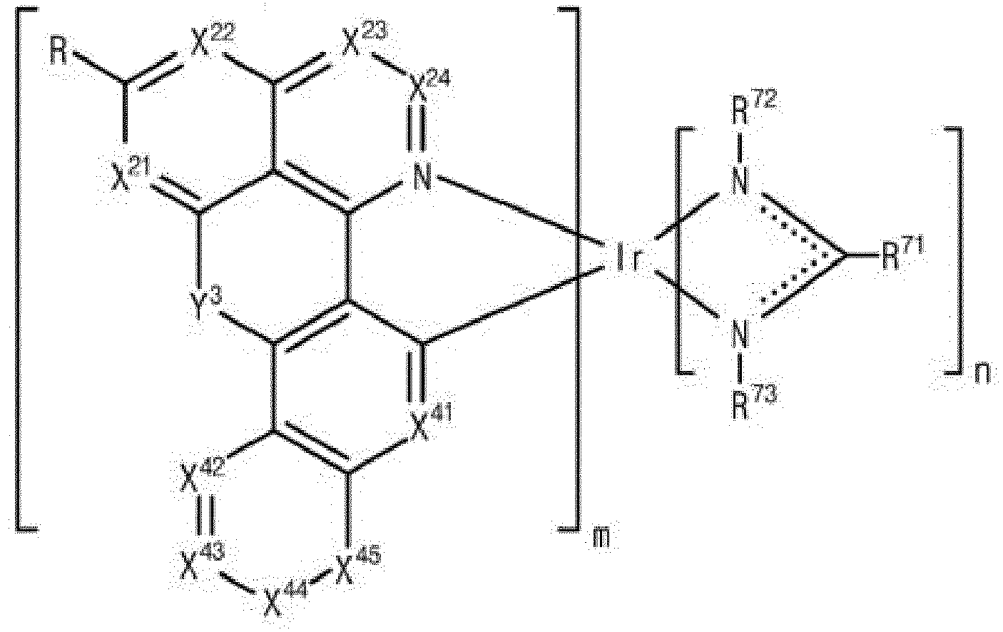


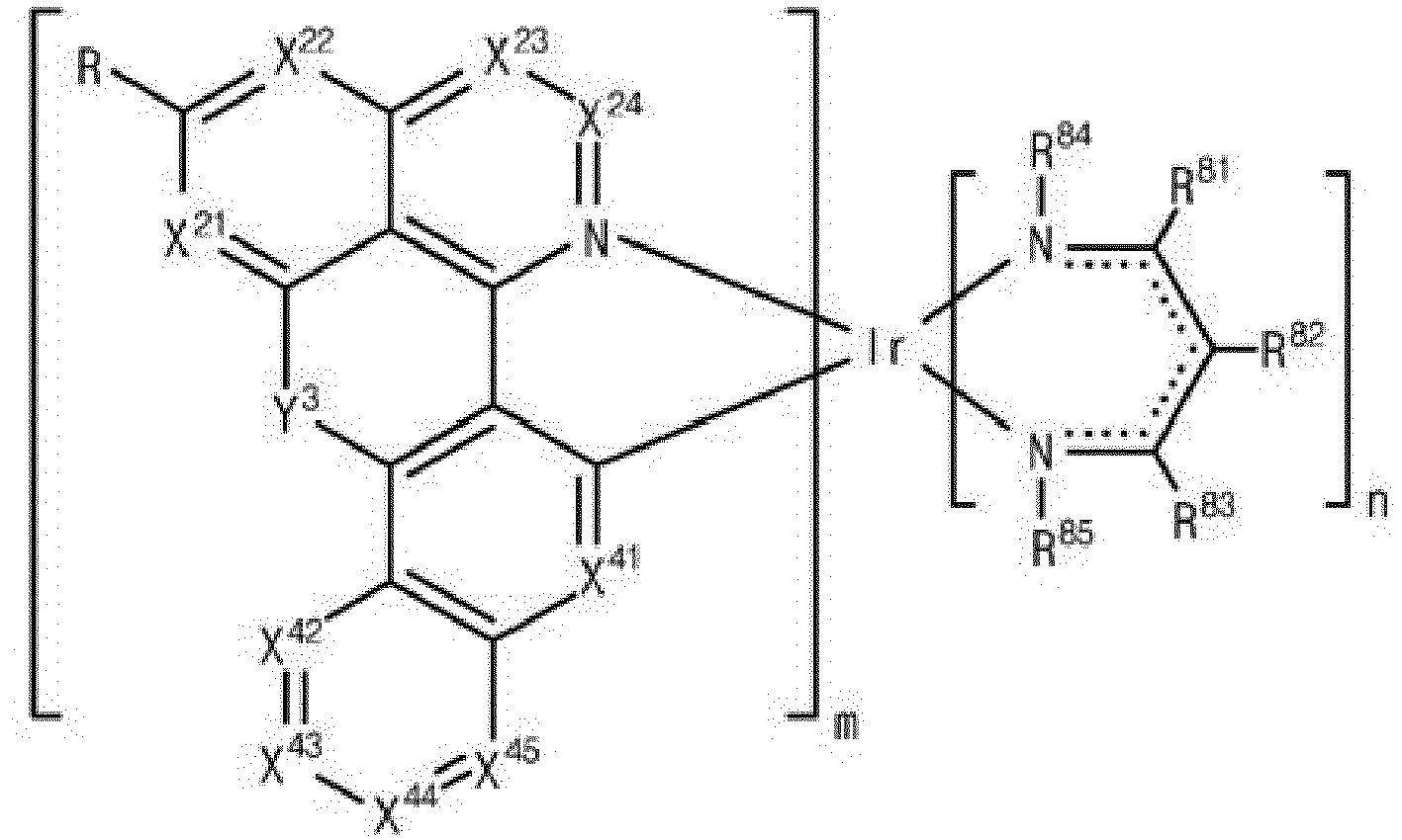


- For example, the
first compound 232 represented by Formula 1-8 can be one of the compounds in Formula 1-24.


- For example, the
first compound 232 represented by Formula 1-9 can be one of the compounds in Formula 1-25.


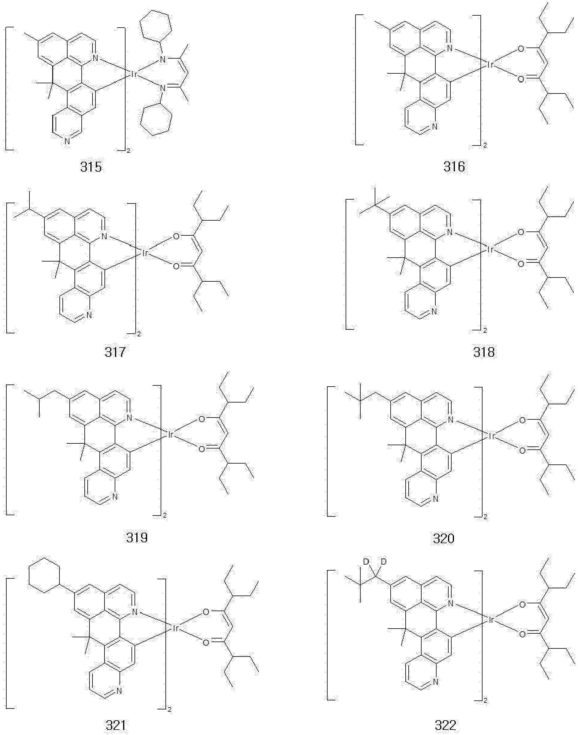


- For example, the
first compound 232 represented by Formula 1-10 can be one of the compounds in Formula 1-26.


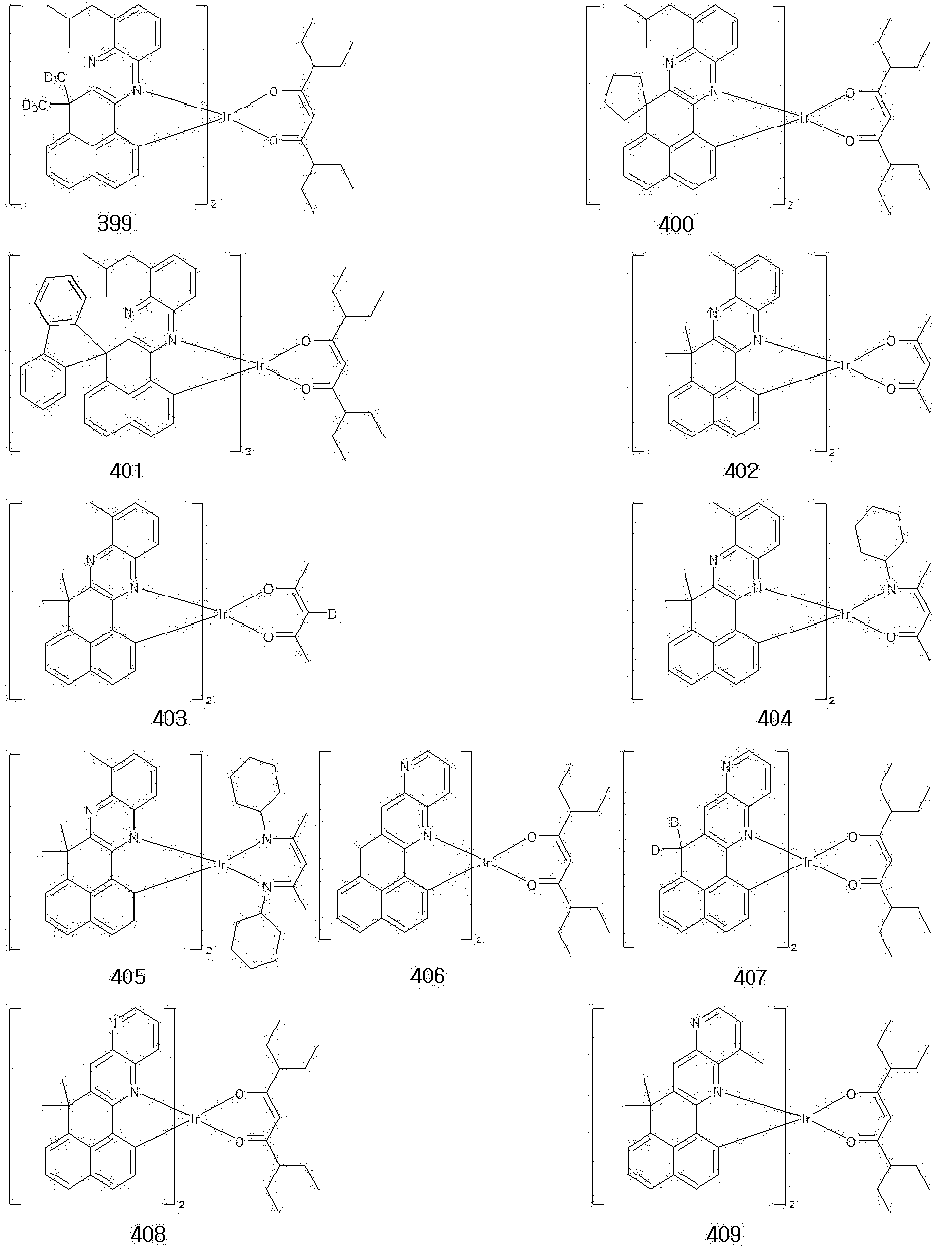


- When Y4 in Formula 1-11 is an unsubstituted or substituted carbon atom, i.e., CH2 or CR2R3, the
first compound 232 can be one of the compounds in Formula 1-27.


- When Y4 in Formula 1-11 is an unsubstituted or substituted hetero atom, i.e., NRa or O, the
first compound 232 can be one of the compounds in Formula 1-28.


- For example, the
first compound 232 can be one of the compounds in Formula 1-29.


-

- Compound A-1 (5-bromoquinoline, 50.0 g, 240.33 mmol), propan-2-ylboronic acid (42.25 g, 480.65 mmol), Pd2(dba)3 (tris(dibenzylideneacetone)dipalladium (0), 6.6 g, 3 mol%), SPhos (2-dicyclichexhylphosphino-2',6'-dimethoxybiphenyl, 9.9 g, 24.03 mmol), potassium phosphate monohydrate (276.71 g, 1.2 mol) and toluene (1000 mL) were put into a reaction vessel, and then the solution was stirred at 120°C for 12 hours. After the reaction was complete, the solution was cooled down to a room temperature and the solution was extracted with ethyl acetate to remove the solvent. A crude product was purified with column chromatography (eluent: ethyl acetate and hexane) to give the compound B-1 (5-isopropylquinoline, 35.4 g, yield: 86%).
MS (m/z): 171.10 -

- The compound B-1 (5-isopropylquinoline, 35.4 g, 206.73 mmol), mCBPA (3-chloroperbenzoic acid, 53.5 g, 310.09 mmol) and dichloromethane (500 mL) were put into a reaction vessel, and then the solution was stirred at room temperature for 3 hours. Sodium sulfite (80 g) was added into the solution, the organic layer was washed with water and then placed under reduced pressure to give the compound C-1 (27.5 g, yield: 71%).
MS (m/z): 187.10 -

- The compound C-1 (27.5 g, 146.87 mmol) dissolved in toluene (500 mL) was put into a reaction vessel, phosphoryl trichloride (POCl3, 45.0 g, 293.74 mmol) and diisopropylethylamine (DIPEA, 38.0 g, 293.74 mmol) were added into the vessel, and then the solution was stirred at 120°C for 4 hours. The reactants ware placed under reduced pressure to remove the solvent and extracted with dichloromethane, and then the organic layer was washed with water. Water was removed with MgSO4, the crude product was filtered and then the solvent was removed. The crude product was purified with column chromatography to give the compound D-1 (2-chloro-5-isopropylquinoline, 11.8 g, yield: 39%).
MS (m/z); 205.07 -

- The compound E-1 (1-naphthoic acid, 50 g, 290.30 mmol) and SOCl2 (200 mL) were put into a reaction vessel, the solution was refluxed for 4 hours, SOCl2 was removed, ethanol (200mL) was added, and then the solution was stirred at 70°C for 7 hours. Water was added, the organic layer was extracted with ether, water was removed with MgSO4 and then the solution was filtered. The solution was placed under reduced pressure to remove the solvent and to give the compound F-1 (ethyl-1-naphtoate, 53.2 g, yield: 90%).
MS (m/z): 200.08 -

- The compound F-1 (ethyl-1-naphtoate, 52.3 g, 261.20 mmol), NBS (N-bromosuccinimide, 51.14 g, 287.32 mmol), Pd(OAc)2 (palladium(II)acetate, 0.6 g, 2.61 mmol), Na2S2O8 (124.4 g, 522.40 mmol) and dichloromethane (500 mL) were put into a reaction vessel, TfOH (Trifluoromethanesulfonic acid, 19.6 g, 130.60 mmol) was added into the reaction vessel, and then the solution was stirred at 70°C for 1 hour. The reactants were cooled to room temperature, the reaction was complete using NaHCO3, and then was extracted with dichloromethane. Water in the organic layer was removed with MgSO4, the solvent was removed, and then the crude product was purified with column chromatography (eluent: petroleum ether and ethyl acetate) to give the compound G-1 (ethyl-8-bromonaphthalene-1-carboxylate, 54.0 g, yield: 74%).
MS (m/z): 277.99 -

- The compound G-1 (ethyl-8-bromonaphthalene-1-carboxylate, 54.0 g, 193.46 mmol), bis(pinacolato)diboron (58.6 g, 232.15 mmol), Pd(dppf)Cl2 ([1,1'-bis(diphenylphosphino)ferrocene]dichloropalladium(II), 7.1 g, 9.67 mmol), KOAc (potassium acetate, 57.0 g, 580.37 mmol) and 1,4-dioxane (500 mL) were put into a reaction vessel, and then the solution was stirred at 100°C for 4 hours. The reactants were cooled to room temperature, extracted with ethyl acetate, then water in the organic layer was removed with MgSO4, and then the solution was filtered and placed under reduced pressure to remove the solvent. The crude product was purified with column chromatography (eluent: hexane and ethyl acetate) to give the compound H-1 (ethyl8-(4,4,5,5-tetramethyl-1,3,2-dioxanborolan-2-yl)naphthalene-1-carboxylate, 54.3 g, yield: 86%).
MS (m/z): 326.17 -
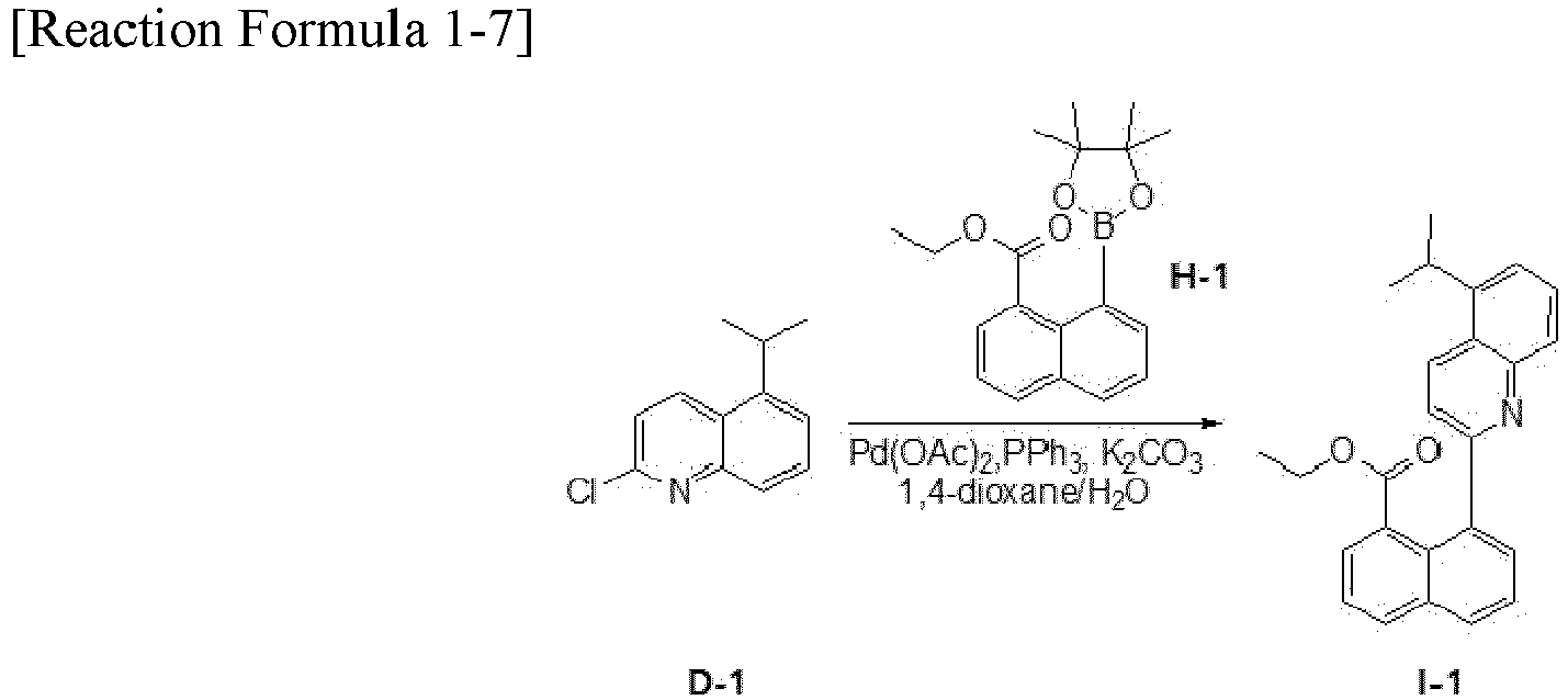
- The compound D-1 (2-chloro-5-isopropylquinoline, 10 g, 48.62 mmol), the compound H-1 (ethyl 8-(4,4,5,5-tetramethyl-1,3,2-dioxanborolan-2-yl)naphthalene-1-caroboylate, 17.45 g, 53.48 mmol), Pd(OAc)2 (0.5 g, 2.43 mmol), PPh3 (chloro(tripphenylphosphine)[2-(2'-amino-1,1'-biphenyl)]palladium(II), 2.6 g, 9.72 mmol), K2CO3 (20.2 g, 145.86 mmol), 1,4-dioxane (100 mL) and water (100 mL) were put into a reaction vessel, and then the solution was stirred at 100°C for 12 hours. The reactants ware cooled to room temperature and extracted with ethyl acetate, water in the organic layer was removed with MgSO4, and then the solution was filtered and placed under reduced pressure to remove the solvent. The crude product was purified with column chromatography (eluent: hexane and ethyl acetate) to give the compound I-1 (ethyl 8-(5-isopropylquinolin-2-yl)naphthalene-1-carboxylate, 13.5 g, yield: 75%).
MS (m/z): 369.17 -

- The compound I-1 (ethyl 8-(5-isopropylquinolin-2-yl)naphthalene-1-carboxylate, 13.5 g, 36.6 mmol) and THF (100 mL) were put into a reaction vessel and then CH3MgBr (21.8 g, 182.70 mmol) was added dropwise into the reaction vessel at 0°C. The solution was raised to room temperature, the reaction was complete after 12 hours, was extracted with ethyl acetate, water in the organic layer was removed with MgSO4, and then the solution was filtered and placed under reduced pressure to remove the solvent. The crude product was purified with column chromatography (eluent: hexane and ethyl acetate) to give the compound J-1 (2-(1-(5-isopropylquinolin-2-yl)naphthalene-8-yl)propan-2-ol, 6.9 g, yield: 53%).
MS (m/z): 355.19 -


- The compound J-1 (2-(1-(5-isopropylquinolin-2-yl)naphthalene-8-yl)propan-2-ol, 20 g, 56.26 mmol) and a mixed aqueous solution (200 mL) of acetic acid and sulfuric acid were put into a reaction vessel, and then the solution was refluxed for 16 hours. After the reaction was complete, the solution was cooled to room temperature, and then the reactants were added dropwise into sodium hydroxide aqueous solution with ice. The organic layer was extracted with dichloromethane and water was removed with MgSO4. The solvent was removed and then the crude product was recrystallized with toluene and ethanol to give the compound K-1 (9-isopropyl-7,7-dimethyl-7H-naphtho[1,8-bc]acridine, 10.25 g, yield: 54%) of yellow solid.
MS (m/z): 337.18 -

- The compound K-1 (10.25 g, 30.37 mmol), 2-ethoxyethanol (200 mL) and distilled water (50 mL) were put into a reaction vessel, the solution was bubbled with nitrogen for 1 hour, IrCl3·H2O (4.4 g, 13.81 mmol) was added into the reaction vessel, and then the solution was refluxed for 2 days. After the reaction was complete, the solution was cooled to room temperature, and then the obtained solid was filtered. The solid was washed with hexane and water and dried to give the compound L-1 (4.0 g, yield: 32%).
-


- The compound L-1 (4.0 g, 2.21 mmol), 3,7-diethylnonane-4,6-dione (4.7 g, 22.09 mmol), Na2CO3 (4.7 g, 441.8 mmol) and 2-ethoxyethanol (100 mL) were put into a reaction vessel, and then the solution was stirred slowly for 24 hours. After the reaction was complete, dichloromethane was added into the reactants to dissolve product, and then the solution was filtered with celite. The solvent was removed, the solid was filtered using filter paper, then the filtered solid was put into isopropanol, and then the solution was stirred. The solution was filtered to remove isopropanol, and the solution was dried and recrystallized with dichloromethane and isopropanol. High purity of compound 369 (2.5 g, yield: 53%) was obtained using a sublimation purification instrument.
MS (m/z): 1076.48 -

- The compound C-2 (ethyl 3-6-(isopropylisoqunolin-1-yl)-naphthoate (14.4 g, yield: 80%) was obtained by repeating the synthesis process of the compound I-1 except that the compound A-2 (1-chloro-6-isopropylisoquinoline, 10 g, 48.62 mmol) and compound B-2 (ethyl 3-(4,4,5,5-tetramethyl-1,3,2-dioxanborolan-2-yl)-2-naphthoate (17.45 g, 53.50 mmol) were used instead of the compound D-1 (2-chloro-5-isopropylquinoline, 10 g, 48.62 mmol) and the compound H-1 (ethyl 8-(4,4,5,5-tetramethyl-1,3,2-dioxanborolan-2-yl)naphthalene-1-carboxlate, respectively.
MS (m/z): 369.17 -

- The compound D-2 (2-(3-(6-isopropylisoquinolin-1-yl)naphthalen-2-yl)propan-2-ol, 6.9 g, yield: 50%) was obtained by repeating the synthesis process of the compound J-1 except that the compound C-2 (ethyl 3-(6-isopropylisoquinolin-1-yl)-2-naphthoate, 14.4 g, 39.0 mmol) was used instead of the compound I-1 (ethyl 8-(5-isopropylquinolin-2-yl)naphthalene-1-caroboxylate, 13.5 g, 36.5 mmol).
MS (m/z): 355.19 -

- The compound E-2 (5-isopropyl-7,7-dimethyl-7H-benzo[de]naphtha[2,3-h]quinolone, 11.39 g, yield: 60%) was obtained by repeating the synthesis process of the Compound K-1 except that the compound D-2 (2-(3-(6-isopropylisoquinolin-1-yl)naphthalen-2-yl)propan-2-ol, 20 g, 56.26 mmol) was used instead of the compound J-1 (2-(1-(5-isopropylquinolin-2-yl)naphthalene-8-yl)propan-2-ol, 20 g, 56.26 mmol).
MS (m/z): 337.18 -


- The compound F-2 (4.7 g, yield: 34%) was obtained by repeating the synthesis process of the Compound L-1 except that the compound E-2 (11.39 g, 33.76 mmol) was used instead of the compound K-1 (10.25 g, 30.37 mmol).
-

- The compound 2 (3.2 g, yield: 57%) was obtained by repeating the synthesis process of compound 369 except that the Compound F-2 (4.7 g, 2.61 mmol) was used instead of the compound L-1 (4.0 g, 2.21 mmol).
MS (m/z): 1076.48 -

- The compound C-3 (ethyl 8-6-(isopropylisoquinolin-3-yl)-naphthoate, 12.6 g, yield: 70%) was obtained by repeating the synthesis process of the compound I-1 except that the compound A-3 (3-chloro-6-isopropylisoquinoline, 10 g, 48.62 mmol) was used instead of the compound D-1 (2-chloro-5-isopropylquinoline, 10 g, 48.62 mmol).
MS (m/z): 369.17 -

- The compound D-3 (2-(8-(6-isopropylisoquinolin-3-yl)naphthalen-1-yl)propan-2-ol, 7.3 g, yield: 60%) was obtained by repeating the synthesis process of the Compound J-1 except that the compound C-3 (ethyl 8-(6-isopropylisoquinolin-3-yl)naphthoate, 12.6 g, 34.0 mmol) was used instead of the compound I-1 (ethyl 8-(5-isopropylquinolin-2-yl)naphthalene-1-caroboxylate, 13.5 g, 36.5 mmol).
MS (m/z): 355.19 -

- The compound E-3 (2-isopropyl-13,13-dimethyl-13H-naphtho[1,8-bc]phenanthridine, 4.3 g, yield: 62%) was obtained by repeating the synthesis process of the Compound K-1 except that the compound D-3 (2-(8-(6-isopropylisoquinolin-3-yl)naphthalen-1-yl)propan-2-ol, 7.3 g, 20.4 mmol) was used instead of the compound J-1 (2-(1-(5-isopropylquinolin-2-yl)naphthalene-8-yl)propan-2-ol, 20 g, 56.26 mmol).
MS (m/z): 337.18 -

- The compound F-3 (1.9 g, yield: 37%) was obtained by repeating the synthesis process of the compound L-1 except that the compound E-3 (2-isopropyl-13,13-dimethyl-13H-naphtho[1,8-bc]phenanthridine, 4.3 g, 12.6 mmol) was used instead of the compound K-1 (10.25 g, 30.37 mmol).
-

- The compound 501 (1.4 g, yield: 60%) was obtained by repeating the synthesis process of compound 369 except that the compound F-3 (1.9 g, 1.07mmol ) was used instead of the compound L-1 (4.0 g, 2.21 mmol).
MS (m/z): 1076.48 -

- The compound C-4 (12.2 g, yield: 68%) was obtained by repeating the synthesis process of the compound I-1 except that the compound A-4 (10 g, 48.62 mmol) and the compound B-4 (17.45 g, 53.48 mmol) were used instead of the compound D-1 (2-chloro-5-isopropylquinoline, 10 g, 48.62 mmol) and the compound H-1 (ethyl 8-(4,4,5,5-tetramethyl-1,3,2-dioxanborolan-2-yl)naphthalene-1-carboxlate (17.45 g, 53.48 mmol), respectively.
MS (m/z): 369.17 -

- The compound D-4 (6.8 g, yield: 58%) was obtained by repeating the synthesis process of the compound J-1 except that the compound C-4 (12.2 g, 33.02 mmol) was used instead of the compound I-1 (ethyl 8-(5-isopropylquinolin-2-yl)naphthalene-1-caroboxylate, 13.5 g, 36.5 mmol).
MS (m/z): 355.19 -

- The compound E-4 (4.1 g, yield: 63%) was obtained by repeating the synthesis process of the compound K-1 except that the compound D-4 (6.8 g, 19.15 mmol) was used instead of the compound J-1 (2-(1-(5-isopropylquinolin-2-yl)naphthalene-8-yl)propan-2-ol, 20 g, 56.26 mmol).
MS (m/z): 337.18 -

- The compound F-4 (2.1 g, yield: 42%) was obtained by repeating the synthesis process of the compound L-1 except that the compound E-4 (4.1 g, 12.15 mmol) was used instead of the compound K-1 (10.25 g, 30.37 mmol).
-

- The compound 182 (1.1 g, yield: 57%) was obtained by repeating the synthesis process of compound 369 except that the compound F-4 (2.1 g, 1.17mmol) was used instead of the compound L-1 (4.0 g, 2.21 mmol).
MS (m/z): 1076.48 -


- The compound C-5 (11.8 g, yield: 78%) was obtained by repeating the synthesis process of the compound I-1 except that the compound A-5 (10 g, 48.62 mmol) and the compound B-5(14.4 g, 53.48 mmol) were used instead of the compound D-1 (2-chloro-5-isopropylquinoline, 10 g, 48.62 mmol) and the compound H-1 (ethyl 8-(4,4,5,5-tetramethyl-1,3,2-dioxanborolan-2-yl)naphthalene-1-carboxlate (17.45 g, 53.48 mmol), respectively.
MS (m/z): 312.16 -

- The compound C-5 (11.8 g, 37.75mmol) and dimethylsulfoxide (DMSO) (200 mL) were put into a reaction vessel, then CuI (10.8 g, 56.66 mmol) was added into the reaction vessel, and then the solution was refluxed at 150°C for 12 hours. After the reaction was complete, the solution was filtered, extracted with ethyl acetate, water in the organic layer was removed with MgSO4, and then the solution was filtered and placed under reduced pressure to remove the solvent. The crude product was purified with column chromatography (eluent: hexane and ethyl acetate) to give the compound D-5 (4.6 g, yield: 39%).
MS (m/z): 310.15 -


- The compound D-5 (4.6 g, 14.82 mmol), 1-iodobenzene (3.3 g, 16.30 mmol) and toluene (200 mL) were put into a reaction vessel, then Pd2(dba)3 (0.7 g, 0.74 mmol), P(t-Bu)3 (Tri-tert-butylphosphine, 0.3 g, 1.48 mmol) and NaOt-Bu (sodium tert-butoxide, 2.8 g, 29.64 mmol) were added into the reaction vessel, and then the solution was refluxed at 100°C for 24 hours. After the reaction was complete, the solution was extracted with ethyl acetate, water in the organic layer was removed with MgSO4, and then the solution was filtered and placed under reduced pressure to remove the solvent. The crude product was purified with column chromatography (eluent: hexane and ethyl acetate) to give the compound E-5 (4.6 g, yield: 81%).
MS (m/z): 386.18 -

- The compound F-5 (2.5 g, yield: 47%) was obtained by repeating the synthesis process of the compound L-1 except that the compound E-5 (4.6 g, 11.90 mmol) was used instead of the compound K-1 (10.25 g, 30.37 mmol).
-


- The compound 154 (1.4 g, yield: 46%) was obtained by repeating the synthesis process of compound 369 except that the compound F-5 (2.5 g, 1.25 mmol) was used instead of the compound L-1 (4.0 g, 2.21 mmol).
MS (m/z): 1174.47 -

- The compound C-6 (11.4 g, yield: 75%) was obtained by repeating the synthesis process of the compound I-1 except that the compound A-6 (10 g, 48.62 mmol) and the compound B-6 (14.4 g, 53.48 mmol) were used instead of the compound D-1 (2-chloro-5-isopropylquinoline, 10 g, 48.62 mmol) and the compound H-1 (ethyl 8-(4,4,5,5-tetramethyl-1,3,2-dioxanborolan-2-yl)naphthalene-1-carboxlate (17.45 g, 53.48 mmol), respectively.
MS (m/z): 312.16 -


- The compound D-6 (6.8 g, yield: 58%) was obtained by repeating the synthesis process of the compound D5 except that the compound C-6 (11.4 g, 35.49 mmol) was used instead of the compound C-5 (11.8 g, 37.77 mmol).
MS (m/z): 310.15 -

- The compound E-6 (5.6 g, yield: 78%) was obtained by repeating the synthesis process of the compound E-5 except that the compound D-6 (5.8 g, 18.61 mmol) was used instead of the compound D-5 (4.6 g, 14.82 mmol).
MS (m/z): 386.18 -

- The compound F-6 (2.8 g, yield: 42%) was obtained by repeating the synthesis process of the compound L-1 except that the compound E-6 (5.6 g, 14.49 mmol) was used instead of the compound K-1 (10.25 g, 30.37 mmol).
-

- The compound 334 (2.0 g, yield: 61%) was obtained by repeating the synthesis process of compound 369 except that the compound F-6 (2.8 g, 1.38 mmol) was used instead of the compound L-1 (4.0 g, 2.21 mmol).
MS (m/z): 1174.47 -

- The compound C-7 (9.0 g, yield: 50%) was obtained by repeating the synthesis process of the compound I-1 except that the compound A-7 (10 g, 48.62 mmol) and the compound B-7 (14.4 g, 53.48 mmol) were used instead of the compound D-1 (2-chloro-5-isopropylquinoline, 10 g, 48.62 mmol) and the compound H-1 (ethyl 8-(4,4,5,5-tetramethyl-1,3,2-dioxanborolan-2-yl)naphthalene-1-carboxlate (17.45 g, 53.48 mmol), respectively.
MS (m/z): 312.16 -


- The compound D-7 (7.4 g, yield: 55%) was obtained by repeating the synthesis process of the compoundD-5 except that the compound C-7 (9.0 g, 28.69 mmol) was used instead of the compound C-5 (11.8 g, 37.77 mmol).
MS (m/z): 310.15 -

- The compound E-7 (4.7 g, yield: 77%) was obtained by repeating the synthesis process of the compound E-5 except that the compound D-7 (4.9 g, 15.78 mmol) was used instead of the compound D-5 (4.6 g, 14.82 mmol).
MS (m/z): 386.18 -

- The compound F-7 (2.6 g, yield: 48%) was obtained by repeating the synthesis process of the compound L-1 except that the compound E-7 (4.7 g, 12.16 mmol) was used instead of the compound K-1 (10.25 g, 30.37 mmol).
-

- The compound 465 (2.0 g, yield: 64%) was obtained by repeating the synthesis process of compound 369 except that the compound F-7 (2.6 g, 1.33mmol) was used instead of the compound L-1 (4.0 g, 2.21 mmol).
MS (m/z): 1174.47 -
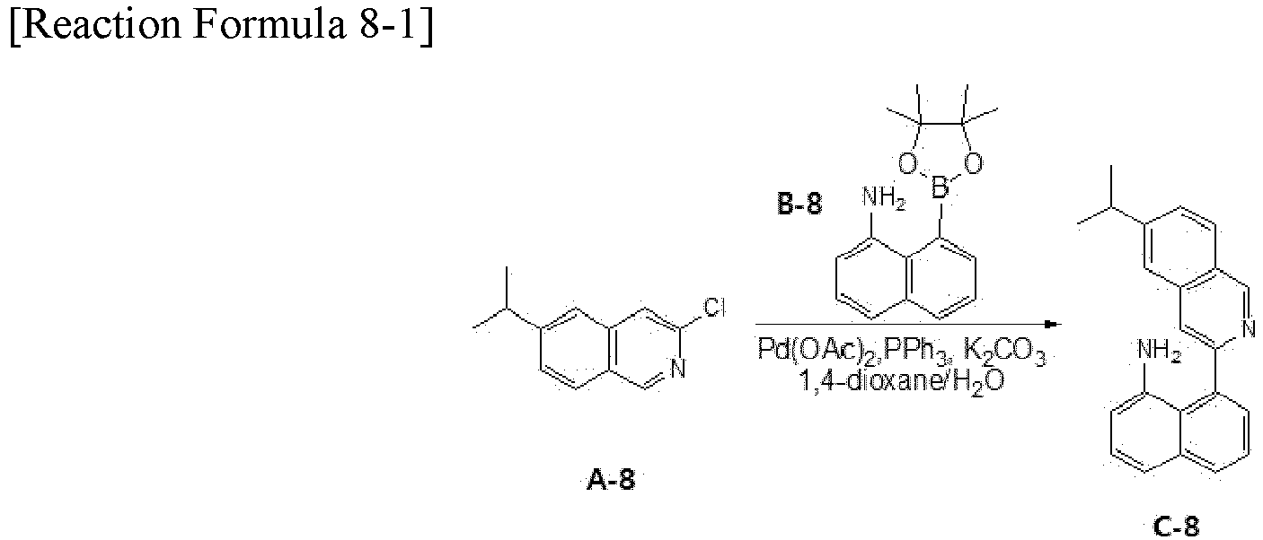
- The compound C-8 (9.0 g, yield: 50%) was obtained by repeating the synthesis process of the compound I-1 except that the compound A-8 (10 g, 48.62 mmol) and the compound B-8 (14.4 g, 53.48 mmol) were used instead of the compound D-1 (2-chloro-5-isopropylquinoline, 10 g, 48.62 mmol) and the compound H-1 (ethyl 8-(4,4,5,5-tetramethyl-1,3,2-dioxanborolan-2-yl)naphthalene-1-carboxlate(17.45 g, 53.48 mmol), respectively.
MS (m/z): 312.16 -


- The compound D-8 (7.4 g, yield: 55%) was obtained by repeating the synthesis process of the compound D-5 except that the compound C-8 (10.0 g, 35.01 mmol) was used instead of the compound C-5 (11.8 g, 37.77 mmol).
MS (m/z): 310.15 -

- The compound E-8 (5.3 g, yield: 83%) was obtained by repeating the synthesis process of the compound E-5 except that the compound D-8 (5.1 g, 15.45 mmol) was used instead of the compound D-5 (4.6 g, 14.82 mmol).
MS (m/z): 386.18 -

- The compound F-8 (2.4 g, yield: 39%) was obtained by repeating the synthesis process of the compound L-1 except that the compound E-8 (5.3 g, 13.66 mmol) was used instead of the compound K-1 (10.25 g, 30.37 mmol).
-

- The compound 582 (1.8 g, yield: 64%) was obtained by repeating the synthesis process of compound 369 except that the compound F-8 (2.4 g, 1.1 mmol) was used instead of the compound L-1 (4.0 g, 2.21 mmol).
MS (m/z): 1174.47 -

- The compound C-9 (9.9 g, yield: 67%) was obtained by repeating the synthesis process of the compound I-1 except that the compound A-9 (10 g, 44.71 mmol) and the compound B-9 (13.3 g, 49.18 mmol) were used instead of the compound D-1 (2-chloro-5-isopropylquinoline, 10 g, 48.62 mmol) and the compound H-1 (ethyl 8-(4,4,5,5-tetramethyl-1,3,2-dioxanborolan-2-yl)naphthalene-1-carboxlate(17.45 g, 53.48 mmol), respectively.
MS (m/z): 331.14 -


- The compound C-9 (9.9 g, 29.88 mmol) and DMF (100 mL) were put into a reaction vessel, and the compound C-9 was dissolved in DMF, K2CO3 (12.4 g, 89.62 mmol) was added into the reaction vessel, and then the solution was stirred at 100°C for 1 hour. After the reaction was complete, the solution was cooled to room temperature and then ethanol (100 mL) was added into the reaction vessel. After the mixture was distilled under reduced pressure, the reactants were recrystallized with chloroform/ethyl acetate to give the compound D-9 (4.9 g, yield: 53%).
MS (m/z): 311.13 -
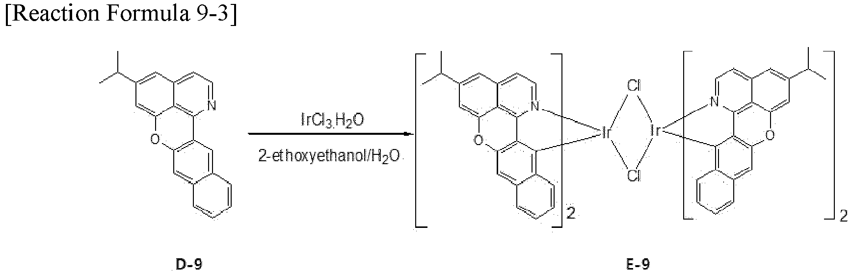
- The compound E-9 (3.1 g, yield: 50%) was obtained by repeating the synthesis process of the compound L-1 except that the compound D-9 (4.9 g, 15.83 mmol) was used instead of the compound K-1 (10.25 g, 30.37 mmol).
-

- The compound 168 (2.0 g, yield: 54%) was obtained by repeating the synthesis process of compound 369 except that the compound E-9 (3.1 g, 1.80 mmol) was used instead of the Compound L-1 (4.0 g, 2.21 mmol).
MS (m/z): 1024.38 -

- The compound C-10 (9.0 g, yield: 64%) was obtained by repeating the synthesis process of the compound I-1 except that the compound A-10 (10 g, 44.71 mmol) and the compound B-10 (13.3 g, 49.18 mmol) were used instead of the compound D-1 (2-chloro-5-isopropylquinoline, 10 g, 48.62 mmol) and the compound H-1 (ethyl 8-(4,4,5,5-tetramethyl-1,3,2-dioxanborolan-2-yl)naphthalene-1-carboxlate(17.45 g, 53.48 mmol), respectively.
MS (m/z): 331.14 -

- The compound D-10 (5.0 g, yield: 55%) was obtained by repeating the synthesis process of the compound D-9 except that the compound C-10 (9.6 g, 29.06 mmol) was used instead of the compound C-9 (9.9 g, 28.88 mmol).
MS (m/z): 311.13 -

- The compound E-10 (3.5 g, yield: 57%) was obtained by repeating the synthesis process of the compound L-1 except that the compound D-10 (5.0 g, 15.98 mmol) was used instead of the compound K-1 (10.25 g, 30.37 mmol).
-

- The compound 348 (1.8 g, yield: 43%) was obtained by repeating the synthesis process of compound 369 except that the compound E-10 (3.5 g, 2.07 mmol) was used instead of the compound L-1 (4.0 g, 2.21 mmol).
MS (m/z): 1024.38 -


- The compound C-11 (7.9 g, yield: 53%) was obtained by repeating the synthesis process of the compound I-1 except that the compound A-11 (10 g, 44.71 mmol) and the compound B-11 (13.3 g, 49.18 mmol) were used instead of the Compound D-1 (2-chloro-5-isopropylquinoline, 10 g, 48.62 mmol) and the compound H-1 (ethyl 8-(4,4,5,5-tetramethyl-1,3,2-dioxanborolan-2-yl)naphthalene-1-carboxlate (17.45 g, 53.48 mmol), respectively.
MS (m/z): 331.14 -

- The compound D-11 (3.8 g, yield: 51%) was obtained by repeating the synthesis process of the compound D-9 except that the compound C-11 (7.9 g, 23.07 mmol) was used instead of the compound C-9 (9.9 g, 28.88 mmol).
MS (m/z): 311.13 -


- The compound E-11 (3.0 g, yield: 63%) was obtained by repeating the synthesis process of the compound L-1 except that the compound D-11 (3.8 g, 12.20 mmol) was used instead of the compound K-1 (10.25 g, 30.37 mmol).
-

- The compound 483 (1.6 g, yield: 44%) was obtained by repeating the synthesis process of compound 369 except that the compound E-11 (3.0 g, 1.75 mmol) was used instead of the compound L-1 (4.0 g, 2.21 mmol).
MS (m/z): 1024.38 -

- The compound C-12 (9.8 g, yield: 66%) was obtained by repeating the synthesis process of the compound I-1 except that the compound A-12 (10 g, 44.71 mmol) and the compound B-12 (13.3 g, 49.18 mmol) were used instead of the compound D-1 (2-chloro-5-isopropylquinoline, 10 g, 48.62 mmol) and the compound H-1 (ethyl 8-(4,4,5,5-tetramethyl-1,3,2-dioxanborolan-2-yl)naphthalene-1-carboxlate(17.45 g, 53.48 mmol), respectively.
MS (m/z): 331.14 -
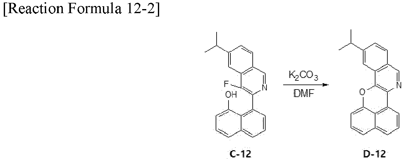
- The compound D-12 (5.0 g, yield: 54%) was obtained by repeating the synthesis process of the compound D-9 except that the compound C-12 (9.8 g, 29.51 mmol) was used instead of the compound C-9 (9.9 g, 28.88 mmol).
MS (m/z): 311.13 -

- The compound E-12 (3.4 g, yield: 55%) was obtained by repeating the synthesis process of the compound L-1 except that the compound D-12 (5.0 g, 15.93 mmol) was used instead of the compound K-1 (10.25 g, 30.37 mmol).
-


- The compound 598 (1.6 g, yield: 39%) was obtained by repeating the synthesis process of compound 369 except that the compound E-12 (3.4 g, 1.99 mmol) was used instead of the compound L-1 (4.0 g, 2.21 mmol).
MS (m/z): 1024.38 -

- The compound A-1 (1-chloro-6-isobutylisoquinoline, 10g, 45.51mmol), ethyl 3-(4,4,5,5-tetramethyl-1,3,2-dioxaborolan-2-yl)-2-naphthoate (16.3g, 50.06mmol), Pd(OAc)2 (0.51g, 2.28mmol), PPh3 (2.39g, 0.91mmol), K2CO3 (18.9g, 136.53mmol), 1-4-dioxane (100mL) and water (100mL) were stirred at 100°C for 12 hours. After cooling to room temperature, extraction was performed with ethyl acetate, and water in the organic layer was removed using MgSO4. Then, the mixture was filtered under reduced pressure to remove the solvent. The mixture was wet-purified using hexane and ethyl acetate to obtain the compound B-1 (10 g, 26.07 mmol). (yield: 57%)
-


- The compound B-1 (ethyl 3-(6-isobutylisoquinolin-1-yl)-2-naphthoate, 10g, 26.07mmol) and THF (100mL) were added, and CH3MgBr (15.5g, 130mmol) was slowly added at 0°C. The temperature was raised to room temperature, and the reaction was terminated after 12 hours. The mixture was extracted with ethyl acetate, water in the organic layer was removed using MgSO4, and the solvent was removed under reduced pressure. The mixture was wet-purified using hexane and ethyl acetate, and the compound C -1 (7g, 18.94mmol) was obtained. (yield: 73%)
-

- The compound C-1 (2-(3-(6-isobutylisoquinolin-1-yl)naphthalen-2-yl)propan-2-ol, 10g, 27.06mmol) was added to a mixed aqueous solution of acetic acid and sulfuric acid (200mL), and the mixture was reflux and stirred for 16 hours. After completion of the reaction, the temperature was lowered to room temperature, and the reactant was slowly added to the sodium hydroxide aqueous solution. After extracting the organic layer using dichloromethane and removing water using MgSO4, the organic solvent was removed under reduced pressure. The mixture was recrystallized using toluene and ethanol to obtain the compound D-1 (5 g, 14.22 mmol) in a yellow solid state. (yield: 53%)
-


- The compound D-1 (5-isobutyl-7,7-dimethyl-7H-benzo[de]naphtho[2,3-h]quinoline, 10g, 28.45mmol), 2-ethoxyethanol (200mL) and distilled water (50mL) were added, and nitrogen was injected to the mixture for 1 hour. IrCl3·H2O (4.5g, 12.93mmol) was put in the reaction vessel and refluxed for 2 days. After completion of the reaction, the temperature was lowered to room temperature and the resulting solid was filtered. After washing the solid with methanol and drying the solid, the compound E-1 (7.0 g, 6.05 mmol) was obtained. (yield: 21%)
-

- The compound E-1 (10g, 8.64mmol), 3,7-diethylnonane-4,6-dione (18.3g, 86.4mmol) and Na2CO3 (18.3g, 172.8mmol) were added and dissolved in 2-ethoxyethanol (100mL). The mixture was slowly stirred for 24 hours. After completion of the reaction, the product was filtered using dichloromethane. After removing the solvent, the solid was filtered. The filtered solid was added to isopropanol and stirred, and then the filtered solid was dried. Recrystallization and sublimation purification using dichloromethane and isopropanol were performed to obtain the compound RD1 with high purity (5g, 4.53mmol). (yield: 52%)
-

- The compound A-2 (1-chloro-6-isobutylisoquinoline, 10g, 45.51mmol), ethyl 2-(4,4,5,5-tetramethyl-1,3,2-dioxaborolan-2-yl)-1-naphthoate (16.3g, 50.06mmol), Pd(OAc)2 (0.51g, 2.28mmol), PPh3 (2.39g, 0.91mmol), K2CO3 (18.9g, 136.53mmol), 1-4-dioxane (100mL) and water (100mL) were stirred at 100°C for 12 hours. After cooling to room temperature, extraction was performed with ethyl acetate, and water in the organic layer was removed using MgSO4. Then, the mixture was filtered under reduced pressure to remove the solvent. The mixture was wet-purified using hexane and ethyl acetate to obtain the compound B-2 (9g, 23.47 mmol). (yield: 52%)
-

- The compound B-2 (ethyl 2-(6-isobutylisoquinolin-1-yl)-1-naphthoate, 10g, 26.07mmol) and THF (100mL) were added, and CH3MgBr (15.5g, 130mmol) was slowly added at 0°C. The temperature was raised to room temperature, and the reaction was terminated after 12 hours. The mixture was extracted with ethyl acetate, water in the organic layer was removed using MgSO4, and the solvent was removed under reduced pressure. The mixture was wet-purified using hexane and ethyl acetate, and the compound C-2 (6g, 16.23mmol) was obtained. (yield: 62%)
-

- The compound C-2 (2-(2-(6-isobutylisoquinolin-1-yl)naphthalen-1-yl)propan-2-ol, 10g, 27.06mmol) was added to a mixed aqueous solution of acetic acid and sulfuric acid (200mL), and the mixture was reflux and stirred for 16 hours. After completion of the reaction, the temperature was lowered to room temperature, and the reactant was slowly added to the sodium hydroxide aqueous solution. After extracting the organic layer using dichloromethane and removing water using MgSO4, the organic solvent was removed under reduced pressure. The mixture was recrystallized using toluene and ethanol to obtain the compound D-2 (4g, 11.38mmol) in a yellow solid state. (yield:42%)
-
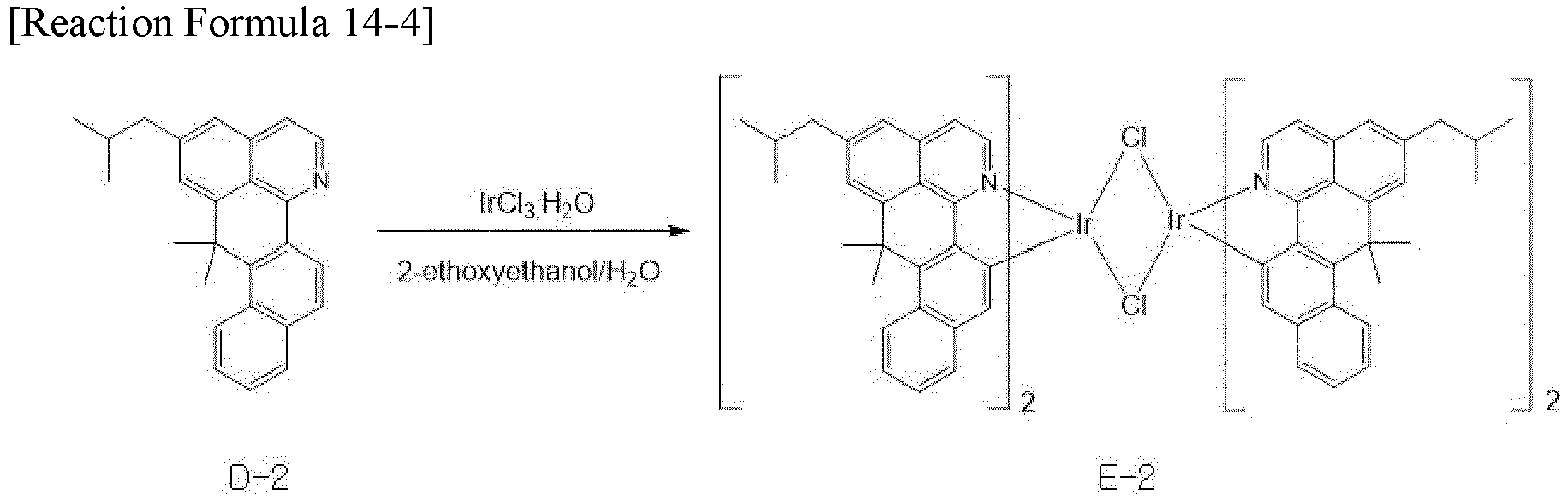
- The compound D-2 (5-isobutyl-7,7-dimethyl-7H-benzo[de]naphtho[1,2-h]quinoline, 10g, 28.45mmol), 2-ethoxyethanol (200mL) and distilled water (50mL) were added, and nitrogen was injected to the mixture for 1 hour. IrCl3·H2O (4.5g, 12.93mmol) was put in the reaction vessel and refluxed for 2 days. After completion of the reaction, the temperature was lowered to room temperature and the resulting solid was filtered. After washing the solid with methanol and drying the solid, the compound E-2 (10g, 8.65mmol) was obtained. (yield: 30%)
-

- The compound E-2 (10g, 8.64mmol), 3,7-diethylnonane-4,6-dione (18.3g, 86.4mmol) and Na2CO3 (18.3g, 172.8mmol) were added and dissolved in 2-ethoxyethanol (100mL). The mixture was slowly stirred for 24 hours. After completion of the reaction, the product was filtered using dichloromethane. After removing the solvent, the solid was filtered. The filtered solid was added to isopropanol and stirred, and then the filtered solid was dried. The mixture was recrystallized and purified using dichloromethane and isopropanol to obtain the compound RD2 with high purity (4g, 3.98mmol). (yield: 46%)
-

- The compound A-3 (5-bromoquinoline, 50g, 240.33mmol), isobutylboronic acid (49g, 480.65mmol), Pd2(dba)3 (6.6g, 3 mol%), Sphos (2-dicyclohexylphosphino-2',6'-dimethoxybiphenyl, 9.9g, 24.03mmol), potassium phosphate monohydrate (276.71g, 1.2mol) and toluene(1000mL) were stirred at 120°C for 12 hours. After completion of the reaction, the temperature was lowered, and the mixture was extracted with ethyl acetate. After the solvent was removed, the mixture was wet-purified using ethyl acetate and hexane to obtain the compound B-3 (35g, 188.92mmol). (yield: 79%)
-

- The compound B-3 (5-isobutylquinoline, 35g, 188.92mmol), 3-chloroperbenzoic acid (57g, 283.38 mmol) and dichloromethane (500mL) were stirred at room temperature for 3 hours. After completion of the reaction, sodium sulfite (80g) was added into the mixture. The organic layer was extracted and the pressure was lowered so that the compound C-3 (27g, 134.15mmol) was obtained. (yield: 71%)
-
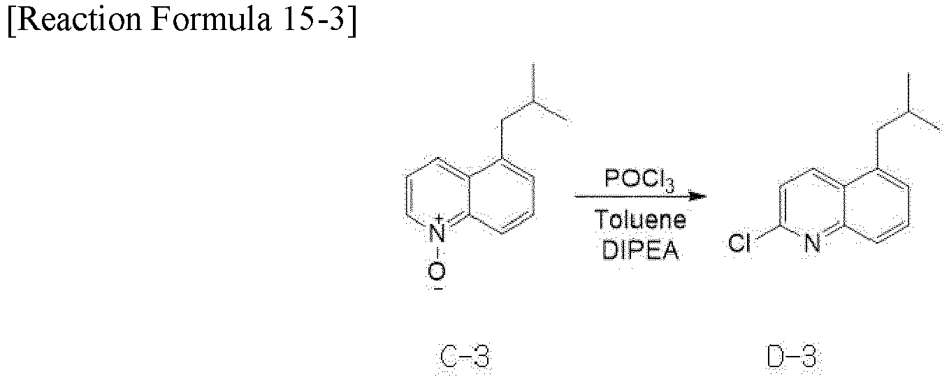
- The compound C-3 (25g, 124.22mmol) and toluene (500mL) were added, and phosphoryl trichloride (38.1g, 248.44mmol) and diisopropylethylamine (32.1g, 248.44mmol) were added into the mixture. The mixture was stirred at the temperature of 120°C for 4 hours. After completion of the reaction, the mixture was extracted with dichloromethane, and the pressure was lowered. The mixture was filtered using MgSO4 under reduced pressure, and the organic solvent was removed. The mixture was wet-purified to obtain the compound D-3 (30g, 91.0mmol). (yield: 73%)
-


- The compound D-3 (10g, 45.51mmol), ethyl 8-(4,4,5,5-tetramethyl-1,3,2-dioxaborolan-2-yl)naphthalene-1-carboxylate (16.33g, 50.06mmol), Pd(OAc)2 (0.5g, 2.28mmol), PPh3 (2.4g, 9.10mmol), K2CO3 (18.9 g, 136.53mmol), 1,4-dioxane (100 mL) and water (100mL) ) were stirred at 100°C for 12 hours. After completion of the reaction, the mixture was extracted with ethyl acetate, and water in the organic layer was removed using MgSO4. The solvent was removed from the mixture by lowering the pressure. The mixture was wet-purified using hexane and ethyl acetate to obtain the compound E-3 (13g, 33.90mmol) was obtained. (yield: 74%)
-

- The compound E-3 (10g, 26.07mmol) and THF (100 mL) were added, and CH3MgBr (15.5g, 130.35mmol) was slowly added at 0°C. After the reaction proceeded at room temperature for 12 hours, the mixture was worked-up using ethyl acetate and MgSO4. The mixture was wet-purified using hexane and ethyl acetate to obtain the compound F-3 (6g, 16.24mmol). (yield: 62%)
-


- The compound F-3 (20g, 54.12mmol) and a mixed aqueous solution of acetic acid and sulfuric acid (200 mL) were added and refluxed for 16 hours. After completion of the reaction, the reactant was slowly added to a cold aqueous sodium hydroxide (cool sodium hydroxide) solution. After work-up using dichloromethane and MgSO4, and the mixture was recrystallized using toluene and ethanol to obtain the compound G-3 (10g, 28.45mmol) in a yellow solid state. (yield: 53%)
-

- The compound G-3 (10g, 28.45mmol), 2-ethoxyethanol (200mL) and distilled water (50mL) were added, and nitrogen was bubbled for 1 hour. Then, IrCl3·H2O (4.5g, 14.22mmol) was added to the reaction vessel, and the mixture was refluxed for 2 days. After completion of the reaction, the temperature was slowly lowered to room temperature and the resulting solid was filtered. The solid was washed with hexane and methanol and dried to obtain the compound H-3 (6.0 g, 5.19 mmol). (yield: 18%)
-


- The compound H-3 (10g, 8.64mmol), 3,7-diethylnonane-4,6-dione (18.3g, 86.4mmol) and Na2CO3 (18.3g, 172.8mmol) was added and dissolved in 2-ethoxyethanol (100mL). The mixture was slowly stirred for 24 hours. After completion of the reaction, the product was filtered using dichloromethane. After removing the solvent, the solid was filtered. The filtered solid was added to isopropanol, and the mixture was stirred. After stirring, the mixture was filtered, and the filtered solid was dried. The solid was recrystallized using dichloromethane and isopropanol and was purified to obtain the compound RD3 (4g, 3.62mmol) with high purity.(yield: 42%)
-

- The compound A-4 (10g, 45.51mmol), ethyl 8-(4,4,5,5-tetramethyl-1,3,2-dioxaborolan-2-yl)naphthalene-1-carboxylate (16.33g, 50.06mmol), Pd(OAc)2 (0.5g, 2.28mmol), PPh3 (2.4g, 9.10mmol), K2CO3 (18.9 g, 136.53mmol), 1,4-dioxane (100 mL)and water (100mL) were stirred at 100°C for 12 hours. After completion of the reaction, the mixture was extracted with ethyl acetate, and water in the organic layer was removed using MgSO4. The solvent was removed from the mixture by lowering the pressure. The mixture was wet-purified using hexane and ethyl acetate to obtain the compound B-4 (13g, 33.90mmol). (yield: 74%)
-
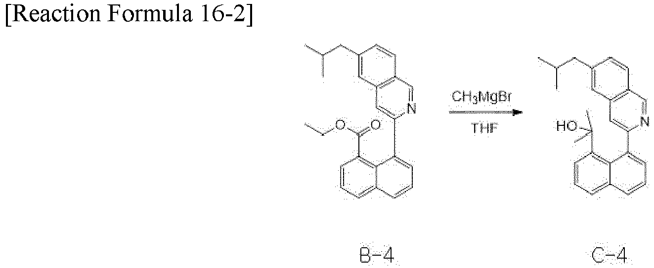
- The compound B-4 (10g, 26.07mmol) and THF (100mL) were added, and CH3MgBr (15.5g, 130mmol) was slowly added at 0°C. The reaction was proceeded for 12 hours, and the mixture was worked-up using ethyl acetate and MgSO4. The mixture was wet-purified using hexane and ethyl acetate, and the compound C-4 (6g, 16.24mmol) was obtained. (yield: 62%)
-

- The compound C-4 (20g, 54.12mmol) was added to a mixed aqueous solution of acetic acid and sulfuric acid (200mL), and the mixture was reflux for 16 hours. After completion of the reaction, a cold sodium hydroxide aqueous solution was slowly added into the mixture. The mixture was worked-up using dichloromethane and MgSO4. The mixture was recrystallized using toluene and ethanol to obtain the compound D-4 (10g, 28.45mmol) in a yellow solid state. (yield: 53%)
-


- The compound D-4 (10g, 28.45mmol), 2-ethoxyethanol (200mL) and distilled water (50mL) were added, and nitrogen was injected to the mixture for 1 hour. IrCl3·H2O (4.5g, 14.22mmol) was put in the reaction vessel and refluxed for 2 days. After completion of the reaction, the temperature was slowly lowered to room temperature and the resulting solid was filtered. After washing the solid with methanol and drying the solid, the compound E-4 (6.0g, 5.19mmol) was obtained. (yield: 18%)
-

- The compound E-4 (10g, 8.64mmol), 3,7-diethylnonane-4,6-dione (18.3g, 86.4mmol) and Na2CO3 (18.3g, 172.8mmol)were added and dissolved in 2-ethoxyethanol (100mL). The mixture was slowly stirred for 24 hours. After completion of the reaction, the product was filtered using dichloromethane. After removing the solvent, the solid was filtered. The filtered solid was added to isopropanol and stirred, and then the filtered solid was dried. The mixture was recrystallized and purified using dichloromethane and isopropanol to obtain the compound RD4 with high purity (4g, 3.62mmol). (yield: 42%)
-


- The compound A-17 (10g, 5.38mmol), 3,7-diethyl-3,7-dimethylnonane-4,6-dione (12.94g, 53.84mmol) and Na2CO3 (11.4g, 107.7mmol)were added and dissolved in 2-ethoxyethanol (100mL). The mixture was slowly stirred for 24 hours. After completion of the reaction, the product was filtered using dichloromethane. After removing the solvent, the solid was filtered. The filtered solid was added to isopropanol and stirred, and then the filtered solid was dried. The mixture was recrystallized using dichloromethane and isopropanol and purified to obtain the compound RD17 with high purity (3.8g, 3.36mmol). (yield: 42%)
-

- Under the nitrogen condition, bromobenzene (1.01g, 6.46mmol) and 50ml of THF were put in a reaction vessel, and the temperature was lowered to -78°C. n-BuLi (2.6ml, 2.5M in hexane) was slowly added into the mixture. After 30 minutes, while maintaining the temperature, N,N'-diisopropylcarbodiimide (0.82g, 6.46mmol) was slowly added, and the mixture was stirred for 30 minutes. The mixture was added to a reaction vessel, in which the compound A-18 (3g, 1.62mmol) was dissolved in 100ml THF, and stirred at 80°C for 8 hours. The temperature of the mixture was lowered to room temperature and volatile substances were removed. After the mixture was recrystallized using THF/pentane and dichloromethane/hexane, purification was performed to obtain the compound RD18 with high purity (2.3g, 2.03mmol).
-

- Under the nitrogen condition, the compound A-19 (3g, 1.62mmol) and THT (100ml) were added in a reaction vessel, and the compound F-1 (0.8g, 3.56mmol) dissolved in THF was slowly added. The mixture was stirred at room temperature for 8 hours. The mixture was extracted using toluene, the solvent was removed, and diethyl ether was added to obtain a solid. The obtained solid was purified to obtain the compound RD19 with high purity (1.1g, 1.01mmol).
-

- Under the nitrogen condition, the compound A-20 (3g, 1.62mmol) and THT (100ml) were added in a reaction vessel, and the compound F-2 (0.8g, 3.56mmol) dissolved in THF was slowly added. The mixture was stirred at room temperature for 8 hours. The mixture was extracted using toluene, the solvent was removed, and diethyl ether was added to obtain a solid. The obtained solid was purified to obtain the compound RD20 with high purity (0.9g, 0.80mmol).
-

- The compound A-21 (10g, 5.38mmol), 3,7-diethyl-3,7-dimethylnonane-4,6-dione (12.94g, 53.84mmol) and Na2CO3 (11.4g, 107.7mmol)were added and dissolved in 2-ethoxyethanol (100mL). The mixture was slowly stirred for 24 hours. After completion of the reaction, the product was filtered using dichloromethane. After removing the solvent, the solid was filtered. The filtered solid was added to isopropanol and stirred, and then the filtered solid was dried. The mixture was recrystallized using dichloromethane and isopropanol and purified to obtain the compound RD21 with high purity (3.4g, 3.00mmol).
-

- Under the nitrogen condition, bromobenzene (1.01g, 6.46mmol) and 50ml of THF were put in a reaction vessel, and the temperature was lowered to -78°C. n-BuLi (2.6ml, 2.5M in hexane) was slowly added into the mixture. After 30 minutes, while maintaining the temperature, N,N'-diisopropylcarbodiimide (0.82g, 6.46mmol) was slowly added, and the mixture was stirred for 30 minutes. The mixture was added to a reaction vessel, in which the compound A-22 (3g, 1.62mmol) was dissolved in 100ml THF, and stirred at 80°C for 8 hours. The temperature of the mixture was lowered to room temperature and volatile substances were removed. After the mixture was recrystallized using THF/pentane and dichloromethane/hexane, purification was performed to obtain the compound RD22 with high purity (2.0g, 1.82mmol).
-

- Under the nitrogen condition, the compound A-23 (3g, 1.62mmol) and THT (100ml) were added in a reaction vessel, and the compound F-1 (0.8g, 3.56mmol) dissolved in THF was slowly added. The mixture was stirred at room temperature for 8 hours. The mixture was extracted using toluene, the solvent was removed, and diethyl ether was added to obtain a solid. The obtained solid was purified to obtain the compound RD23 with high purity (2.5g, 2.29mmol).
-

- Under the nitrogen condition, the compound A-24 (3g, 1.62mmol) and THT (100ml) were added in a reaction vessel, and the compound F-2 (0.8g, 3.56mmol) dissolved in THF was slowly added. The mixture was stirred at room temperature for 8 hours. The mixture was extracted using toluene, the solvent was removed, and diethyl ether was added to obtain a solid. The obtained solid was purified to obtain the compound RD24 with high purity (2.2g, 1.95mmol).
-
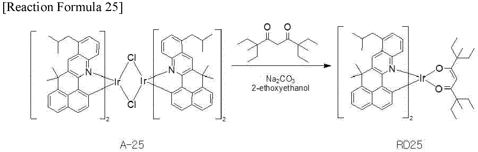
- The compound A-25 (10g, 5.38mmol), 3,7-diethyl-3,7-dimethylnonane-4,6-dione (12.94g, 53.84mmol) and Na2CO3 (11.4g, 107.7mmol)were added and dissolved in 2-ethoxyethanol (100mL). The mixture was slowly stirred for 24 hours. After completion of the reaction, the product was filtered using dichloromethane. After removing the solvent, the solid was filtered. The filtered solid was added to isopropanol and stirred, and then the filtered solid was dried. The mixture was recrystallized using dichloromethane and isopropanol and purified to obtain the compound RD25 with high purity (3.3g, 2.91mmol).
-

- Under the nitrogen condition, bromobenzene (1.01g, 6.46mmol) and 50ml of THF were put in a reaction vessel, and the temperature was lowered to -78°C. n-BuLi (2.6ml, 2.5M in hexane) was slowly added into the mixture. After 30 minutes, while maintaining the temperature, N,N'-diisopropylcarbodiimide (0.82g, 6.46mmol) was slowly added, and the mixture was stirred for 30 minutes. The mixture was added to a reaction vessel, in which the compound A-26 (3g, 1.62mmol) was dissolved in 100ml THF, and stirred at 80°C for 8 hours. The temperature of the mixture was lowered to room temperature and volatile substances were removed. After the mixture was recrystallized using THF/pentane and dichloromethane/hexane, purification was performed to obtain the compound RD26 with high purity (2.1g, 1.92mmol).
-
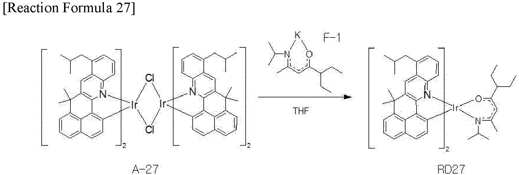
- Under the nitrogen condition, the compound A-27 (3g, 1.62mmol) and THT (100ml) were added in a reaction vessel, and the compound F-1 (0.8g, 3.56mmol) dissolved in THF was slowly added. The mixture was stirred at room temperature for 8 hours. The mixture was extracted using toluene, the solvent was removed, and diethyl ether was added to obtain a solid. The obtained solid was purified to obtain the compound RD27 with high purity (2.2g, 2.02mmol).
-

- Under the nitrogen condition, the compound A-28 (3g, 1.62mmol) and THT (100ml) were added in a reaction vessel, and the compound F-2 (0.8g, 3.56mmol) dissolved in THF was slowly added. The mixture was stirred at room temperature for 8 hours. The mixture was extracted using toluene, the solvent was removed, and diethyl ether was added to obtain a solid. The obtained solid was purified to obtain the compound RD28 with high purity (1.9g, 1.68mmol).
-

- The compound A-29 (10g, 5.38mmol), 3,7-diethyl-3,7-dimethylnonane-4,6-dione (12.94g, 53.84mmol) and Na2CO3 (11.4g, 107.7mmol)were added and dissolved in 2-ethoxyethanol (100mL). The mixture was slowly stirred for 24 hours. After completion of the reaction, the product was filtered using dichloromethane. After removing the solvent, the solid was filtered. The filtered solid was added to isopropanol and stirred, and then the filtered solid was dried. The mixture was recrystallized using dichloromethane and isopropanol and purified to obtain the compound RD29 with high purity (3.9g, 3.44mmol).
-

- Under the nitrogen condition, bromobenzene (1.01g, 6.46mmol) and 50ml of THF were put in a reaction vessel, and the temperature was lowered to -78°C. n-BuLi (2.6ml, 2.5M in hexane) was slowly added into the mixture. After 30 minutes, while maintaining the temperature, N,N'-diisopropylcarbodiimide (0.82g, 6.46mmol) was slowly added, and the mixture was stirred for 30 minutes. The mixture was added to a reaction vessel, in which the compound A-30 (3g, 1.62mmol) was dissolved in 100ml THF, and stirred at 80°C for 8 hours. The temperature of the mixture was lowered to room temperature and volatile substances were removed. After the mixture was recrystallized using THF/pentane and dichloromethane/hexane, purification was performed to obtain the compound RD30 with high purity (2.7g, 2.46mmol).
-

- Under the nitrogen condition, the compound A-31 (3g, 1.62mmol) and THT (100ml) were added in a reaction vessel, and the compound F-1 (0.8g, 3.56mmol) dissolved in THF was slowly added. The mixture was stirred at room temperature for 8 hours. The mixture was extracted using toluene, the solvent was removed, and diethyl ether was added to obtain a solid. The obtained solid was purified to obtain the compound RD31 with high purity (2.0g, 1.84mmol).
-

- Under the nitrogen condition, the compound A-32 (3g, 1.62mmol) and THT (100ml) were added in a reaction vessel, and the compound F-2 (0.8g, 3.56mmol) dissolved in THF was slowly added. The mixture was stirred at room temperature for 8 hours. The mixture was extracted using toluene, the solvent was removed, and diethyl ether was added to obtain a solid. The obtained solid was purified to obtain the compound RD32 with high purity (1.8g, 1.59mmol).
- The
second compound 234 has an excellent hole-dominant property (characteristic) and is represented by Formula 2-1.
- one of X12 and X13 is a nitrogen atom (N), and the other one of X12 and X13 is an oxygen atom (O) or a sulfur atom (S);
- each of R4, R5 and R6 is independently selected from the group consisting of an unsubstituted or substituted C6-C30 aryl group and an unsubstituted or substituted C3-C30 heteroaryl group; L is selected from the group consisting of an unsubstituted or substituted C6-C30 arylene group and an unsubstituted or substituted C3-C30 heteroarylene group; and a is 0 or 1.
- For example, R4, R5 and R6 may be same or different. The C6-C30 aryl group, the C3-C30 heteroaryl group, the C6-C30 arylene group and the C3-C30 heteroarylene group may be substituted with a C1-C10 alkyl group or a C6-C30 aryl group.
- For example, R4 may be selected from an unsubstituted or substituted C6-C30 aryl. L may be selected from an unsubstituted or substituted C6-C30 arylene group, or a may be 0.
- In an exemplary embodiment, R4 may be an unsubstituted C6-C30 aryl group, e.g., phenyl. Each of R5 and R6 may be independently selected from the group consisting of a substituted unsubstituted C6-C30 aryl group, e.g., phenyl, naphthyl or biphenyl, a substituted C6-C30 aryl group, e.g., 9,9-dimethylfluorenyl, and an unsubstituted C3-C30 heteroaryl group, e.g., dibenzofuranyl or dibenzothiophenyl. L may be a substituted C6-C30 arylene group, e.g., phenylene.
- In an exemplary embodiment, one of X12 and X13 may be N, and the other one of X12 and X13 may be O, and each of R4, R5 and R6 may be an unsubstituted or substituted C6-C30 aryl group.
- In an exemplary embodiment, R4 may be phenyl. R5 and R6 may be different, R5 may be phenyl or biphenyl, and R6 may be independently selected from naphthyl, biphenyl and 9,9-dimethylfluorenyl.
- For example, the
second compound 234 can be one of the compounds in Formula 2-2.


- The third compound 236 has an excellent electron-dominant property (characteristic) and is represented by Formula 3-1.

- X is NR8, O or S, and R8 is selected from the group consisting of an unsubstituted or substituted C1-C10 alkyl group, an unsubstituted or substituted C6-C30 aryl group and an unsubstituted or substituted C3-C30 heteroaryl group, and
- R7 is selected from the group consisting of an unsubstituted or substituted C6-C30 aryl group and an unsubstituted or substituted C3-C30 heteroaryl group.
- For example, each of R7 and R8 may be independently selected from an unsubstituted or substituted C6-C30 aryl group.
- In an exemplary embodiment, R7 may be selected from phenyl, biphenyl, naphthyl and 9,9-dimethylfluorenyl, and R8 may be selected from phenyl, naphthyl and biphenyl.
- In Formula 3-1, a linking position (or a linking site) of a X-containing fused-ring to a benzocarbazole moiety (or a naphtho benzofuran moiety) can be specified. Namely, Formula 3-1 can be represented by Formula 3-2.

- In Formula 3-1, a linking position between a X-containing fused-ring and a benzocarbazole moiety (or a naphtho benzofuran moiety) can be specified. Namely, Formula 3-1 can be represented by Formula 3-3.


- For example, the third compound 236 can be one of the compounds in Formula 3-4.


- The
HIL 210 is positioned between thefirst electrode 160 and theHTL 220. The HIL 210 can include at least one compound selected from the group consisting of 4,4',4"-tris(3-methylphenylamino)triphenylamine (MTDATA), 4,4',4"-tris(N,N-diphenyl-amino)triphenylamine(NATA), 4,4',4"-tris(N-(naphthalene-1-yl)-N-phenyl-amino)triphenylamine(1T-NATA), 4,4',4"-tris(N-(naphthalene-2-yl)-N-phenyl-amino)triphenylamine(2T-NATA), copper phthalocyanine (CuPc), tris(4-carbazoyl-9-yl-phenyl)amine (TCTA), N,N'-diphenyl-N,N'-bis(1-naphthyl)-1,1'-biphenyl-4,4"-diamine (NPB or NPD), 1,4,5,8,9,11-hexaazatriphenylenehexacarbonitrile(dipyrazino[2,3-f:2'3'-h]quinoxaline-2,3,6,7,10,11-hexacarbonitrile (HAT-CN), 1,3,5-tris[4-(diphenylamino)phenyl]benzene(TDAPB), poly(3,4-ethylenedioxythiphene)polystyrene sulfonate (PEDOT/PSS), and N-(biphenyl-4-yl)-9,9-dimethyl-N-(4-(9-phenyl-9H-carbazol-3-yl)phenyl)-9H-fluoren-2-amine, but it is not limited thereto. TheHIL 210 can have a thickness of 10 to 200A, preferably 50 to 150Å. - The
HTL 220 is positioned between theHIL 210 and thered EML 230. The HTL 220 can include at least one compound selected from the group consisting of N,N'-diphenyl-N,N'-bis(3-methylphenyl)-1,1'-biphenyl-4,4'-diamine(TPD),NPB(or NPD), 4,4'-bis(N-carbazolyl)-1,1'-biphenyl(CBP), poly[N,N'-bis(4-butylphenyl)-N,N'-bis(phenyl)-benzidine](poly-TPD), (poly[(9,9-dioctylfluorenyl-2,7-diyl)-co-(4,4'-(N-(4-sec-butylphenyl)diphenylamine))] (TFB), di-[4-(N,N-di-p-tolyl-amino)-phenyl]cyclohexane(TAPC), 3,5-di(9H-carbazol-9-yl)-N,N-diphenylaniline(DCDPA), N-(biphenyl-4-yl)-9,9-dimethyl-N-(4-(9-phenyl-9H-carbazol-3-yl)phenyl)-9H-fluoren-2-amine, N-(biphenyl-4-yl)-N-(4-(9-phenyl-9H-carbazol-3-yl)phenyl)biphenyl-4-amine, and a compound in Formula 4, but it is not limited thereto. TheHTL 220 can have a thickness of 500 to 900A, preferably 600 to 800A.

- The
ETL 240 is positioned between thered EML 230 and thesecond electrode 164 and includes at least one of an oxadiazole-containing compound, a triazole-containing compound, a phenanthroline-containing compound, a benzoxazole-containing compound, a benzothiazole-containing compound, a benzimidazole-containing compound, and a triazine-containing compound. For example, the ETL 240 can include at least one compound selected from the group consisting of tris-(8-hydroxyquinoline aluminum (Alq3),2-biphenyl-4-yl-5-(4-t-butylphenyl)-1,3,4-oxadiazole (PBD), spiro-PBD, lithium quinolate (Liq), 1,3,5-tris(N-phenylbenzimidazol-2-yl)benzene (TPBi), bis(2-methyl-8-quinolinolato-N1,O8)-(1,1'-biphenyl-4-olato)aluminum (BAlq), 4,7-diphenyl-1,10-phenanthroline (Bphen), 2,9-bis(naphthalene-2-yl)-4,7-diphenyl-1,10-phenanthroline(NBphen), 2,9-dimethyl-4,7-diphenyl-1,10-phenathroline(BCP), 3-(4-biphenyl)-4-phenyl-5-tert-butylphenyl-1,2,4-triazole(TAZ), 4-(naphthalen-1-yl)-3,5-diphenyl-4H-1,2,4-triazole(NTAZ), 1,3,5-tri(p-pyrid-3-yl-phenyl)benzene (TpPyPB), 2,4,6-tris(3'-(pyridin-3-yl)biphenyl-3-yl)1,3,5-triazine(TmPPPyTz), Poly[9,9-bis(3'-((N,N-dimethyl)-N-ethylammonium)-propyl)-2,7-fluorene]-alt-2,7-(9,9-dioctylfluorene)](PFNBr), tris(phenylquinoxaline) (TPQ), and diphenyl-4-triphenylsilyl-phenylphosphine oxide(TSPO1), but it is not limited thereto. TheETL 240 can have a thickness of 100 to 500A, preferably 200 to 400A. - The
EIL 250 is positioned between theETL 240 and thesecond electrode 164. TheEIL 250 at least one of an alkali halide compound, such as LiF, CsF, NaF, or BaF2, and an organo-metallic compound, such as Liq, lithium benzoate, or sodium stearate, but it is not limited thereto. TheEIL 250 can have a thickness of 1 to 20A, preferably 5 to 15A. - The EBL, which is positioned between the
HTL 220 and thered EML 230 to block the electron transfer from thered EML 230 to theHTL 220, can include at least one compound selected from the group consisting of TCTA, tris[4-(diethylamino)phenyl]amine, N-(biphenyl-4-yl)-9,9-dimethyl-N-(4-(9-phenyl-9H-carbazol-3-yl)phenyl)-9H-fluoren-2-amine, TAPC, MTDATA, 1,3-bis(carbazol-9-yl)benzene (mCP), 3,3'-bis(N-carbazolyl)-1,1'-biphenyl (mCBP), CuPc,N,N'-bis[4-[bis(3-methylphenyl)amino]phenyl]-N,N'-diphenyl-[1,1'-biphenyl]-4,4'-diamine (DNTPD), TDAPB, DCDPA, and 2,8-bis(9-phenyl-9H-carbazol-3-yl)dibenzo[b,d]thiophene), but it is not limited thereto. - The HBL, which is positioned between the
ETL 240 and thered EML 230 to block the hole transfer from thered EML 230 to theETL 240, can include the above material of theETL 240. For example, the material of the HBL has a HOMO energy level being lower than a material of thered EML 230 and can be at least one compound selected from the group consisting of BCP, BAlq, Alq3, PBD, spiro-PBD, Liq, bis-4,6-(3,5-di-3-pyridylphenyl)-2-methylpyrimidine (B3PYMPM), bis[2-(diphenylphosphino)phenyl]ether oxide(DPEPO), 9-(6-9H-carbazol-9-yl)pyridine-3-yl)-9H-3,9'-bicarbazole, and TSPO1, but it is not limited thereto. - As illustrated above, the OLED D1 is positioned in the red pixel region, and the
red EML 230 of the OLED D1 includes thefirst compound 232, which is represented by Formula 1-1, being a dopant, thesecond compound 234, which is represented by Formula 2-1, being a first host or a p-type host and the third compound 236, which is represented by Formula 3-1, being a second host or an n-type host. As a result, in the OLED D1, the driving voltage is decreased, and the luminous efficiency and the luminous lifespan is increased. -
FIG. 4 is a cross-sectional view illustrating an OLED according to a third embodiment of the present disclosure. - As shown in
FIG. 4 , the OLED D2 includes first andsecond electrodes layer 162 therebetween. The organic emittinglayer 162 includes a first emitting part 710 including a firstred EML 720 and a second emittingpart 730 including a secondred EML 740. In addition, the organic emittinglayer 162 can further include a charge generation layer (CGL) 750 between the first and second emittingparts 710 and 730. - For example, the
first electrode 160 can include a transparent conductive material, e.g., ITO or IZO, and thesecond electrode 164 can include one of Al, Mg, Ag, AlMg and MgAg. - The
CGL 750 is positioned between the first and second emittingparts 710 and 730 so that the first emitting part 710, theCGL 750 and the second emittingpart 730 are sequentially stacked on thefirst electrode 160. Namely, the first emitting part 710 is positioned between thefirst electrode 160 and theCGL 750, and the second emittingpart 730 is positioned between thesecond electrode 164 and theCGL 750. - As illustrated below, the first emitting part 710 includes the first
red EML 720. The firstred EML 720 includes afirst compound 722 as a red dopant (e.g., a red emitter), a second compound 724 as a p-type host (e.g., a first host) and a third compound 726 as an n-type host (e.g., a second host). In the firstred EML 720, thefirst compound 722 is represented by Formula 1-1, the second compound 724 is represented by Formula 2-1, and the third compound 726 is represented by Formula 3-1. - The first
red EML 720 can have a thickness of 100 to 400Å, e.g., 200 to 400Å, but it is not limited thereto. - In the first
red EML 720, each of the second and third compounds 724 and 726 can have a weight % being greater than thefirst compound 722. For example, in the firstred EML 720, thefirst compound 722 can have a weight % of 1 to 20, e.g., 5 to 15. - In addition, in the first
red EML 720, a ratio of the weight % between the second compound 724 and the third compound 726 can be 1:3 to 3:1. For example, in the firstred EML 720, the second and third compounds 724 and 726 can have the same weight %. - The first emitting part 710 can further include at least one of a first HTL 714 under the first
red EML 720 and afirst ETL 716 on or over the firstred EML 720. Namely, the first HTL 714 is disposed between the firstred EML 720 and thefirst electrode 160, and thefirst ETL 716 is disposed between the firstred EML 720 and theCGL 750. - In addition, the first emitting part 710 can further include an
HIL 712 between thefirst electrode 160 and the first HTL 714. - As illustrated below, the second emitting
part 730 includes the secondred EML 740. The secondred EML 740 includes afirst compound 742, e.g., a fourth compound, as a red dopant (e.g., a red emitter), a second compound 744, e.g., a fifth compound, as a p-type host (e.g., a first host) and a third compound 746, e.g., a sixth compound, as an n-type host (e.g., a second host). In the secondred EML 740, thefirst compound 742 is represented by Formula 1-1, the second compound 744 is represented by Formula 2-1, and the third compound 746 is represented by Formula 3-1. - The second
red EML 740 can have a thickness of 100 to 400Å, e.g., 200 to 400Å, but it is not limited thereto. - In the second
red EML 740, each of the second and third compounds 744 and 746 can have a weight % being greater than thefirst compound 742. For example, in the secondred EML 740, thefirst compound 742 can have a weight % of 1 to 20, e.g., 5 to 15. - In addition, in the second
red EML 740, a ratio of the weight % between the second compound 744 and the third compound 746 can be 1:3 to 3:1. For example, in the secondred EML 740, the second and third compounds 744 and 746 can have the same weight %. - The
first compound 742 in the secondred EML 740 and thefirst compound 722 in the firstred EML 720 can be same or different. The second compound 744 in the secondred EML 740 and the second compound 724 in the firstred EML 720 can be same or different. The third compound 746 in the secondred EML 740 and the third compound 726 in the firstred EML 720 can be same or different. - The second emitting
part 730 can further include at least one of asecond HTL 732 under the secondred EML 740 and asecond ETL 734 on or over the secondred EML 740. Namely, thesecond HTL 732 is disposed between the secondred EML 740 and theCGL 750, and thesecond ETL 734 is disposed between the secondred EML 740 and thesecond electrode 164. - In addition, the second emitting
part 730 can further include anEIL 736 between thesecond ETL 734 and thesecond electrode 164. - The
CGL 750 is positioned between the first and second emittingparts 710 and 730. Namely, the first and second emittingparts 710 and 730 are connected to each other through theCGL 750. TheCGL 750 can be a P-N junction type CGL of an N-type CGL 752 and a P-type CGL 754. - The N-
type CGL 752 is positioned between thefirst ETL 716 and thesecond HTL 732, and the P-type CGL 754 is positioned between the N-type CGL 752 and thesecond HTL 732. - In the OLED D2, at least one of the first and second
red EMLs -
FIG. 5 is a cross-sectional view illustrating an organic light emitting display device according to a fourth embodiment of the present disclosure. - As shown in
FIG. 5 , the organic light emittingdisplay device 300 includes afirst substrate 310, where a red pixel region RP, a green pixel region GP and a blue pixel region BP are defined, asecond substrate 370 facing thefirst substrate 310, an OLED D, which is positioned between the first andsecond substrates color filter layer 380 between the OLED D and thesecond substrate 370. - Each of the first and
second substrates second substrates - A
buffer layer 320 is formed on the substrate, and the TFT Tr corresponding to each of the red, green and blue pixel regions RP, GP and BP is formed on thebuffer layer 320. Thebuffer layer 320 can be omitted. - A
semiconductor layer 322 is formed on thebuffer layer 320. Thesemiconductor layer 322 can include an oxide semiconductor material or polycrystalline silicon. - A
gate insulating layer 324 is formed on thesemiconductor layer 322. Thegate insulating layer 324 can be formed of an inorganic insulating material such as silicon oxide or silicon nitride. - A
gate electrode 330, which is formed of a conductive material, e.g., metal, is formed on thegate insulating layer 324 to correspond to a center of thesemiconductor layer 322. - An interlayer insulating
layer 332, which is formed of an insulating material, is formed on thegate electrode 330. The interlayer insulatinglayer 332 can be formed of an inorganic insulating material, e.g., silicon oxide or silicon nitride, or an organic insulating material, e.g., benzocyclobutene or photo-acryl. - The interlayer insulating
layer 332 includes first and second contact holes 334 and 336 exposing both sides of thesemiconductor layer 322. The first and second contact holes 334 and 336 are positioned at both sides of thegate electrode 330 to be spaced apart from thegate electrode 330. - A
source electrode 340 and adrain electrode 342, which are formed of a conductive material, e.g., metal, are formed on theinterlayer insulating layer 332. - The
source electrode 340 and thedrain electrode 342 are spaced apart from each other with respect to thegate electrode 330 and respectively contact both sides of thesemiconductor layer 322 through the first and second contact holes 334 and 336. - The
semiconductor layer 322, thegate electrode 330, thesource electrode 340 and thedrain electrode 342 constitute the TFT Tr. The TFT Tr serves as a driving element. Namely, the TFT Tr can correspond to the driving TFT Td (ofFIG. 1 ). - The gate line and the data line cross each other to define the pixel, and the switching TFT is formed to be connected to the gate and data lines. The switching TFT is connected to the TFT Tr as the driving element.
- In addition, the power line, which can be formed to be parallel to and spaced apart from one of the gate and data lines, and the storage capacitor for maintaining the voltage of the gate electrode of the TFT Tr in one frame can be further formed.
- A
planarization layer 350, which includes adrain contact hole 352 exposing thedrain electrode 342 of the TFT Tr, is formed to cover the TFT Tr. - A
first electrode 360, which is connected to thedrain electrode 342 of the TFT Tr through thedrain contact hole 352, is separately formed in each pixel region and on theplanarization layer 350. Thefirst electrode 360 can be an anode and can be formed of a conductive material, e.g., a transparent conductive oxide (TCO), having a relatively high work function. Thefirst electrode 360 can further include a reflection electrode or a reflection layer. For example, the reflection electrode or the reflective layer can include Ag or aluminum-palladium-copper (APC). In a top-emission type organic light emittingdisplay device 300, thefirst electrode 360 can have a structure of ITO/Ag/ITO or ITO/APC/ITO. - A
bank layer 366 is formed on theplanarization layer 350 to cover an edge of thefirst electrode 360. Namely, thebank layer 366 is positioned at a boundary of the pixel and exposes a center of thefirst electrode 360 in the pixel. Since the OLED D emits the white light in the red, green and blue pixel regions RP, GP and BP, the organic emittinglayer 362 can be formed as a common layer in the red, green and blue pixel regions RP, GP and BP without separation. Thebank layer 366 can be formed to prevent a current leakage at an edge of thefirst electrode 360 and can be omitted. - An organic emitting
layer 362 is formed on thefirst electrode 360. As illustrated below, the organic emittinglayer 362 includes at least two emitting parts, and each emitting part includes at least one EML. As a result, the OLED D emits the white light. - At least one of the emitting parts includes a first compound, e.g., a red dopant, represented by Formula 1-1, a second compound, e.g., a p-type host or a first host, represented by Formula 2-1 and a third compound, e.g., an n-type host or a second host, represented by Formula 3-1 to emit the red light.
- A
second electrode 364 is formed over thesubstrate 310 where the organic emittinglayer 362 is formed. - In the organic light emitting
display device 300, since the light emitted from the organic emittinglayer 362 is incident to thecolor filter layer 380 through thesecond electrode 364, thesecond electrode 364 has a thin profile for transmitting the light. - The
first electrode 360, the organic emittinglayer 362 and thesecond electrode 364 constitute the OLED D. - The
color filter layer 380 is positioned over the OLED D and includes ared color filter 382, agreen color filter 384 and ablue color filter 386 respectively corresponding to the red, green and blue pixel regions RP, GP and BP. Thered color filter 382 can include at least one of red dye and red pigment, thegreen color filter 384 can include at least one of green dye and green pigment, and theblue color filter 386 can include at least one of blue dye and blue pigment. - The
color filter layer 380 can be attached to the OLED D by using an adhesive layer. Alternatively, thecolor filter layer 380 can be formed directly on the OLED D. - An encapsulation film can be formed to prevent penetration of moisture into the OLED D. For example, the encapsulation film can include a first inorganic insulating layer, an organic insulating layer and a second inorganic insulating layer sequentially stacked, but it is not limited thereto. The encapsulation film can be omitted.
- A polarization plate for reducing an ambient light reflection can be disposed over the top-emission type OLED D. For example, the polarization plate can be a circular polarization plate.
- In the OLED of
FIG. 5 , the first andsecond electrodes color filter layer 380 is disposed over the OLED D. Alternatively, when the first andsecond electrodes color filter layer 380 can be disposed between the OLED D and thefirst substrate 310. - A color conversion layer can be formed between the OLED D and the
color filter layer 380. The color conversion layer can include a red color conversion layer, a green color conversion layer and a blue color conversion layer respectively corresponding to the red, green and blue pixel regions RP, GP and BP. The white light from the OLED D is converted into the red light, the green light and the blue light by the red, green and blue color conversion layer, respectively. For example, the color conversion layer can include a quantum dot. Accordingly, the color purity of the organic light emittingdisplay device 300 can be further improved. - The color conversion layer can be included instead of the
color filter layer 380. - As described above, in the organic light emitting
display device 300, the OLED D in the red, green and blue pixel regions RP, GP and BP emits the white light, and the white light from the organic light emitting diode D passes through thered color filter 382, thegreen color filter 384 and theblue color filter 386. As a result, the red light, the green light and the blue light are provided from the red pixel region RP, the green pixel region GP and the blue pixel region BP, respectively. - In
FIG. 5 , the OLED D emitting the white light is used for a display device. Alternatively, the OLED D can be formed on an entire surface of a substrate without at least one of the driving element and the color filter layer to be used for a lightening device. The display device and the lightening device each including the OLED D of the present disclosure can be referred to as an organic light emitting device. -
FIG. 6 is a cross-sectional view illustrating an OLED according to a fifth embodiment of the present disclosure. - As shown in
FIG. 6 , in the OLED D3, the organic emittinglayer 362 includes a first emittingpart 430 including ared EML 410, a second emittingpart 440 including a firstblue EML 450 and a third emittingpart 460 including a secondblue EML 470. In addition, the organic emittinglayer 362 can further include afirst CGL 480 between the first and second emittingparts second CGL 490 between the first and third emittingpart part 430 can further include agreen EML 420. - The
first electrode 360 is an anode, and thesecond electrode 364 is a cathode. One of the first andsecond electrodes second electrodes - The second emitting
part 440 is positioned between thefirst electrode 360 and the first emittingpart 430, and the third emittingpart 460 is positioned between the first emittingpart 430 and thesecond electrode 364. In addition, the second emittingpart 440 is positioned between thefirst electrode 360 and thefirst CGL 480, and the third emittingpart 460 is positioned between thesecond CGL 490 and thesecond electrode 364. Namely, the second emittingpart 440, thefirst CGL 480, the first emittingpart 430, thesecond CGL 460 and the third emittingpart 460 are sequentially stacked on thefirst electrode 360. - In the first emitting
part 430, thegreen EML 420 is positioned on thered EML 410. - The first emitting
part 430 can further include at least one of afirst HTL 432 under thered EML 410 and afirst ETL 434 over thered EML 410. When the first emittingpart 430 includes thegreen EML 420, thefirst ETL 434 is positioned on thegreen EML 420. - The second emitting
part 440 can further include at least one of asecond HTL 444 under the firstblue EML 450 and asecond ETL 448 on the firstblue EML 450. In addition, the second emittingpart 440 can further include anHIL 442 between thefirst electrode 360 and thefirst HTL 444. - The second emitting
part 440 can further include at least one of a first EBL between thesecond HTL 444 and the firstblue EML 450 and a first HBL between the firstblue EML 450 and thesecond ETL 448. - The third
emitting part 460 can further include at least one of athird HTL 462 under the secondblue EML 470 and athird ETL 466 on the secondblue EML 470. In addition, the third emittingpart 460 can further include anEIL 468 between thesecond electrode 364 and thethird ETL 466. - The third
emitting part 460 can further include at least one of a first EBL between thethird HTL 462 and the secondblue EML 470 and a first HBL between the secondblue EML 470 and thethird ETL 466. - For example, the
HIL 442 can include at least one of MTDATA, NATA, 4,4',4"-tris(N-(naphthalene-1-yl)-N-phenyl-amino)triphenylamine 1T-NATA, 2T-NATA, CuPc, TCTA, NPB, HAT-CN, TDAPB, PEDOT/PSS and N-(biphenyl-4-yl)-9,9-dimethyl-N-(4-(9-phenyl-9H-carbazol-3-yl)phenyl)-9H-fluoren-2-amine. - Each of the first to
third HTLs Formula 4. - Each of the first to
third ETLs - The
EIL 468 can include at least one of an alkali halide compound, such as LiF, CsF, NaF, or BaF2, and an organo-metallic compound, such as Liq, lithium benzoate, or sodium stearate. - The
first CGL 480 is positioned between the first and second emittingparts second CGL 490 is positioned between the first and third emittingparts parts first CGL 480, and the first and third emittingparts second CGL 490. Thefirst CGL 480 can be a P-N junction type CGL of an N-type CGL 482 and a P-type CGL 484, and thesecond CGL 490 can be a P-N junction type CGL of an N-type CGL 492 and a P-type CGL 494. - In the
first CGL 480, the N-type CGL 482 is positioned between thefirst HTL 432 and thesecond ETL 448, and the P-type CGL 484 is positioned between the N-type CGL 482 and thefirst HTL 432. - In the
second CGL 490, the N-type CGL 492 is positioned between thefirst ETL 434 and thethird HTL 462, and the P-type CGL 494 is positioned between the N-type CGL 492 and thethird HTL 462. - Each of the N-
type CGL 482 of thefirst CGL 480 and the N-type CGL 492 of thesecond CGL 490 can be an organic layer doped with an alkali metal, e.g., Li, Na, K or Cs, and/or an alkali earth metal, e.g., Mg, Sr, Ba or Ra. For example, each of the N-type CGL 482 of thefirst CGL 480 and the N-type CGL 492 of thesecond CGL 490 can include an organic material, e.g., 4,7-dipheny-1,10-phenanthroline(Bphen) or MTDATA, as a host, and the alkali metal and/or the alkali earth metal as a dopant can be doped with a weight % of about 0.01 to 30. - Each of the P-
type CGL 484 of thefirst CGL 480 and the P-type CGL 494 of thesecond CGL 490 can include at least one of an inorganic material, which is selected from the group consisting of tungsten oxide (WOx), molybdenum oxide (MoOx), beryllium oxide (Be2O3), vanadium oxide (V2O5) and their combination, and an organic material, which is selected from the group consisting of NPD, HAT-CN, F4TCNQ, TPD, N,N,N',N'-tetranaphthyl-benzidine (TNB), TCTA, N,N'-dioctyl-3,4,9,10-perylenedicarboximide (PTCDI-C8) and their combination. - The
red EML 410 includes afirst compound 412 as a red dopant (e.g., a red emitter), asecond compound 414 as a p-type host (e.g., a first host) and athird compound 416 as an n-type host (e.g., a second host). In thered EML 410, thefirst compound 412 is represented by Formula 1-1, thesecond compound 414 is represented by Formula 2-1, and thethird compound 416 is represented by Formula 3-1. - In the
red EML 410, each of the second andthird compounds first compound 412. For example, in thered EML 410, thefirst compound 412 can have a weight % of 1 to 20, e.g., 5 to 15. - In addition, in the
red EML 410, a ratio of the weight % between thesecond compound 414 and thethird compound 416 can be 1:3 to 3:1. For example, in thered EML 410, the second andthird compounds - In the first emitting
part 410, thegreen EML 420 includes a green host and a green dopant. The green dopant can be one of a phosphorescent compound, a fluorescent compound and a delayed fluorescent compound. For example, in thegreen EML 420, the host can be 4,4'-bis(carbazol-9-yl)biphenyl (CBP), and the green dopant can be fac tris(2-phenylpyridine)iridium Ir(ppy)3 or tris(8-hydroxyquinolino)aluminum (Alq3). - The first
blue EML 450 in the second emittingpart 440 includes a first blue host and a first blue dopant, and the secondblue EML 470 in the third emittingpart 460 includes a second blue host and a second blue dopant. - For example, each of the first and second blue hosts can be independently selected from the group consisting of mCP, 9-(3-(9H-carbazol-9-yl)phenyl)-9H-carbazole-3-carbonitrile (mCP-CN), mCBP, CBP-CN, 9-(3-(9H-Carbazol-9-yl)phenyl)-3-(diphenylphosphoryl)-9H-carbazole (mCPPO1) 3,5-Di(9H-carbazol-9-yl)biphenyl (Ph-mCP), TSPO1, 9-(3'-(9H-carbazol-9-yl)-[1,1'-biphenyl]-3-yl)-9H-pyrido[2,3-b]indole (CzBPCb), bis(2-methylphenyl)diphenylsilane (UGH-1), 1,4-bis(triphenylsilyl)benzene (UGH-2), 1,3-bis(triphenylsilyl)benzene (UGH-3), 9,9-spiorobifluoren-2-yl-diphenylphosphine oxide (SPPO1) and 9,9'-(5-(triphenylsilyl)-1,3-phenylene)bis(9H-carbazole) (SimCP).
- For example, each of the first and second blue dopants can be independently selected from the group consisting of perylene, 4,4'-bis[4-(di-p-tolylamino)styryl]biphenyl (DPAVBi), 4-(di-p-tolylamino)-4-4'-[(di-p-tolylamino)styryl]stilbene (DPAVB), 4,4'-bis[4-(diphenylamino)styryl]biphenyl (BDAVBi), 2,7-bis(4-diphenylamino)styryl)-9,9-spiorfluorene (spiro-DPVBi), [1,4-bis[2-[4-[N,N-di(p-tolyl)amino]phenyl]vinyl] benzene (DSB), 1-4-di-[4-(N,N-diphenyl)amino]styryl-benzene (DSA), 2,5,8,11-tetra-tetr-butylperylene (TBPe), bis(2-hydroxylphenyl)-pyridine)beryllium (Bepp2), 9-(9-Phenylcarbazole-3-yl)-10-(naphthalene-1-yl)anthracene (PCAN), mer-tris(1-phenyl-3-methylimidazolin-2-ylidene-C,C(2)'iridium(III) (mer-Ir(pmi)3), fac-Tris(1,3-diphenyl-benzimidazolin-2-ylidene-C,C(2)'iridium(III) (fac-Ir(dpbic)3), bis(3,4,5-trifluoro-2-(2-pyridyl)phenyl-(2-carboxypyridyl)iridium(III) (Ir(tfpd)2pic), tris(2-(4,6-difluorophenyl)pyridine))iridium(III) (Ir(Fppy)3) and bis[2-(4,6-difluorophenyl)pyridinato-C2,N](picolinato)iridium(III) (FIrpic).
- In an exemplary aspect, each of the first and second
blue EMLs - As illustrated above, the OLED D3 of the present disclosure includes the first emitting
part 430 including thered EML 410 and thegreen EML 420, the second emittingpart 440 including the firstblue EML 450 and the third emittingpart 460 including the secondblue EML 470. As a result, the OLED D3 emits the white light. - In addition, the
red EML 410 includes thefirst compound 412, which is represented by Formula 1-1, as a red dopant, thesecond compound 414, which is represented by Formula 2-1, as a first host or a p-type host, and thethird compound 416, which is represented by Formula 3-1, as a second host or an n-type host. As a result, the OLED D3 has advantages in the driving voltage, the luminous efficiency and the luminous lifespan. -
FIG. 7 is a cross-sectional view illustrating an OLED according to a sixth embodiment of the present disclosure. - As shown in
FIG. 7 , in the OLED D4, the organic emittinglayer 362 includes a first emittingpart 530 including ared EML 510 andgreen EML 520 and a yellow-green EML 525, a second emittingpart 540 including a firstblue EML 550 and a third emittingpart 560 including a thirdblue EML 570. In addition, the organic emittinglayer 362 can further include afirst CGL 580 between the first and second emittingparts second CGL 590 between the first and third emittingpart - The
first electrode 360 is an anode, and thesecond electrode 364 is a cathode. One of the first andsecond electrodes second electrodes - The second emitting
part 540 is positioned between thefirst electrode 360 and the first emittingpart 530, and the third emittingpart 560 is positioned between the first emittingpart 530 and thesecond electrode 364. In addition, the second emittingpart 540 is positioned between thefirst electrode 360 and thefirst CGL 580, and the third emittingpart 560 is positioned between thesecond CGL 590 and thesecond electrode 364. Namely, the second emittingpart 540, thefirst CGL 580, the first emittingpart 530, thesecond CGL 560 and the third emittingpart 560 are sequentially stacked on thefirst electrode 360. - In the first emitting
part 530, the yellow-green EML 525 is positioned between thered EML 510 and thegreen EML 520. Namely, thered EML 510, the yellow-green EML 525 and thegreen EML 520 are sequentially stacked so that the first emittingpart 530 includes an EML having a triple-layered structure. - The first emitting
part 530 can further include at least one of afirst HTL 532 under thered EML 510 and afirst ETL 534 over thered EML 510. - The second emitting
part 540 can further include at least one of asecond HTL 544 under the firstblue EML 550 and asecond ETL 548 on the firstblue EML 550. In addition, the second emittingpart 540 can further include anHIL 542 between thefirst electrode 360 and thefirst HTL 544. - The second emitting
part 540 can further include at least one of a first EBL between thesecond HTL 544 and the firstblue EML 550 and a first HBL between the firstblue EML 550 and thesecond ETL 548. - The third
emitting part 560 can further include at least one of athird HTL 562 under the secondblue EML 570 and athird ETL 566 on the secondblue EML 570. In addition, the third emittingpart 560 can further include anEIL 568 between thesecond electrode 364 and thethird ETL 566. - The third
emitting part 560 can further include at least one of a first EBL between thethird HTL 562 and the secondblue EML 570 and a first HBL between the secondblue EML 570 and thethird ETL 566. - For example, the
HIL 542 can include at least one of MTDATA, NATA, 4,4',4"-tris(N-(naphthalene-1-yl)-N-phenyl-amino)triphenylamine 1T-NATA, 2T-NATA, CuPc, TCTA, NPB, HAT-CN, TDAPB, PEDOT/PSS and N-(biphenyl-4-yl)-9,9-dimethyl-N-(4-(9-phenyl-9H-carbazol-3-yl)phenyl)-9H-fluoren-2-amine. - Each of the first to
third HTLs Formula 4. - Each of the first to
third ETLs - The
EIL 568 can include at least one of an alkali halide compound, such as LiF, CsF, NaF, or BaF2, and an organo-metallic compound, such as Liq, lithium benzoate, or sodium stearate. - The
first CGL 580 is positioned between the first and second emittingparts second CGL 590 is positioned between the first and third emittingparts parts first CGL 580, and the first and third emittingparts second CGL 590. Thefirst CGL 580 can be a P-N junction type CGL of an N-type CGL 582 and a P-type CGL 584, and thesecond CGL 590 can be a P-N junction type CGL of an N-type CGL 592 and a P-type CGL 594. - In the
first CGL 580, the N-type CGL 582 is positioned between thefirst HTL 532 and thesecond ETL 548, and the P-type CGL 584 is positioned between the N-type CGL 582 and thefirst HTL 532. - In the
second CGL 590, the N-type CGL 592 is positioned between thefirst ETL 534 and thethird HTL 562, and the P-type CGL 594 is positioned between the N-type CGL 592 and thethird HTL 562. - Each of the N-
type CGL 582 of thefirst CGL 580 and the N-type CGL 592 of thesecond CGL 590 can be an organic layer doped with an alkali metal, e.g., Li, Na, K or Cs, and/or an alkali earth metal, e.g., Mg, Sr, Ba or Ra. For example, each of the N-type CGL 582 of thefirst CGL 580 and the N-type CGL 592 of thesecond CGL 590 can include an organic material, e.g., 4,7-dipheny-1,10-phenanthroline(Bphen) or MTDATA, as a host, and the alkali metal and/or the alkali earth metal as a dopant can be doped with a weight % of about 0.01 to 30. - Each of the P-
type CGL 584 of thefirst CGL 580 and the P-type CGL 594 of thesecond CGL 590 can include at least one of an inorganic material, which is selected from the group consisting of tungsten oxide (WOx), molybdenum oxide (MoOx), beryllium oxide (Be2O3), vanadium oxide (V2O5) and their combination, and an organic material, which is selected from the group consisting of NPD, HAT-CN, F4TCNQ, TPD, N,N,N',N'-tetranaphthyl-benzidine (TNB), TCTA, N,N'-dioctyl-3,4,9,10-perylenedicarboximide (PTCDI-C8) and their combination. - The
red EML 510 includes afirst compound 512 as a red dopant (e.g., a red emitter), asecond compound 514 as a p-type host (e.g., a first host) and athird compound 516 as an n-type host (e.g., a second host). In thered EML 510, thefirst compound 512 is represented by Formula 1-1, thesecond compound 514 is represented by Formula 2-1, and thethird compound 516 is represented by Formula 3-1. - In the
red EML 510, each of the second andthird compounds first compound 512. For example, in thered EML 510, thefirst compound 512 can have a weight % of 1 to 20, e.g., 5 to 15. - In addition, in the
red EML 510, a ratio of the weight % between thesecond compound 514 and thethird compound 516 can be 1:3 to 3:1. For example, in thered EML 510, the second andthird compounds - In the first emitting
part 530, thegreen EML 520 includes a green host and a green dopant. The green dopant can be one of a phosphorescent compound, a fluorescent compound and a delayed fluorescent compound. In addition, in the first emittingpart 530, the yellow-green EML 525 includes a yellow-green host and a yellow-green dopant. The yellow-green dopant can be one of a phosphorescent compound, a fluorescent compound and a delayed fluorescent compound. - The first
blue EML 550 in the second emittingpart 540 includes a first blue host and a first blue dopant, and the secondblue EML 570 in the third emittingpart 560 includes a second blue host and a second blue dopant. - For example, each of the first and second blue hosts can be independently selected from the group consisting of mCP, mCP-CN, mCBP, CBP-CN, mCPPO1 Ph-mCP, TSPO1, CzBPCb, UGH-1, UGH-2, UGH-3, SPPO1 and SimCP.
- For example, each of the first and second blue dopants can be independently selected from the group consisting of perylene, DPAVBi, DPAVB, BDAVBi, spiro-DPVBi, DSB, DSA, TBPe, Bepp2, PCAN, mer-Ir(pmi)3, fac-Ir(dpbic)3, Ir(tfpd)2pic, Ir(Fppy)3 and FIrpic.
- In an exemplary aspect, each of the first and second
blue EMLs - As illustrated above, the OLED D4 of the present disclosure includes the first emitting
part 530 including thered EML 510, thegreen EML 520 and the yellow-green EML 525, the second emittingpart 540 including the firstblue EML 550 and the third emittingpart 560 including the secondblue EML 570. As a result, the OLED D4 emits the white light. - In addition, the
red EML 510 includes thefirst compound 512, which is represented by Formula 1-1, as a red dopant, thesecond compound 514, which is represented by Formula 2-1, as a first host or a p-type host, and thethird compound 516, which is represented by Formula 3-1, as a second host or an n-type host. As a result, the OLED D4 has advantages in the driving voltage, the luminous efficiency and the luminous lifespan. -
FIG. 8 is a cross-sectional view illustrating an OLED according to a seventh embodiment of the present disclosure. - As shown in
FIG. 8 , in the OLED D5, the organic emittinglayer 362 includes a first emittingpart 630 including ared EML 610 and agreen EML 620 and a second emittingpart 640 including ablue EML 650. In addition, the organic emittinglayer 362 can further include aCGL 660 between the first and second emittingparts - The
first electrode 360 is an anode, and thesecond electrode 364 is a cathode. One of the first andsecond electrodes second electrodes - The first emitting
part 630 is positioned between theCGL 660 and thesecond electrode 364, and the second emittingpart 640 is positioned between theCGL 660 and thefirst electrode 360. Alternatively, the first emittingpart 630 can be positioned between theCGL 660 and thefirst electrode 360, and the second emittingpart 640 can be positioned between theCGL 660 and thesecond electrode 364. - In the first emitting
part 630, thegreen EML 620 is positioned on thered EML 610. - The first emitting
part 630 can further include at least one of afirst HTL 632 under thered EML 610 and a first ETL 634 over thered EML 610. When the first emittingpart 630 includes thegreen EML 620, the first ETL 634 is positioned on thegreen EML 620. In addition, the first emittingpart 630 can further include anEIL 636 between the first ETL 634 and thesecond electrode 364. - The second emitting
part 640 can further include at least one of asecond HTL 644 under theblue EML 650 and asecond ETL 646 on theblue EML 650. In addition, the second emittingpart 640 can further include anHIL 642 between thefirst electrode 360 and thefirst HTL 644. - For example, the
HIL 642 can include at least one of MTDATA, NATA, 4,4',4"-tris(N-(naphthalene-1-yl)-N-phenyl-amino)triphenylamine 1T-NATA, 2T-NATA, CuPc, TCTA, NPB, HAT-CN, TDAPB, PEDOT/PSS and N-(biphenyl-4-yl)-9,9-dimethyl-N-(4-(9-phenyl-9H-carbazol-3-yl)phenyl)-9H-fluoren-2-amine. - Each of the first and second HTLs 632 and 644 can include at least one of TPD,NPB, CBP, poly-TPD, TFB, TAPC, DCDPA, N-(biphenyl-4-yl)-9,9-dimethyl-N-(4-(9-phenyl-9H-carbazol-3-yl)phenyl)-9H-fluoren-2-amine, N-(biphenyl-4-yl)-N-(4-(9-phenyl-9H-carbazol-3-yl)phenyl)biphenyl-4-amine, and the compound in
Formula 4. - Each of the first and second ETLs 634 and 646 can include at least one of Alq3,PBD, spiro-PBD, Liq, TPBi, BAlq, Bphen, NBphen, BCP, TAZ, NTAZ, TpPyPB, TmPPPyTz, PFNBr, TPQ, and TSPO1.
- The
EIL 636 can include at least one of an alkali halide compound, such as LiF, CsF, NaF, or BaF2, and an organo-metallic compound, such as Liq, lithium benzoate, or sodium stearate. - The
CGL 660 is positioned between the first and second emittingparts parts CGL 660. - The
CGL 660 can be a P-N junction type CGL of an N-type CGL 662 and a P-type CGL 664. - In the
CGL 660, the N-type CGL 662 is positioned between thefirst HTL 632 and thesecond ETL 646, and the P-type CGL 664 is positioned between the N-type CGL 662 and thefirst HTL 632. - The N-
type CGL 662 can be an organic layer doped with an alkali metal, e.g., Li, Na, K or Cs, and/or an alkali earth metal, e.g., Mg, Sr, Ba or Ra. For example, the N-type CGL 662 can include an organic material, e.g., 4,7-dipheny-1,10-phenanthroline(Bphen) or MTDATA, as a host, and the alkali metal and/or the alkali earth metal as a dopant can be doped with a weight % of about 0.01 to 30. - The P-
type CGL 664 can include at least one of an inorganic material, which is selected from the group consisting of tungsten oxide (WOx), molybdenum oxide (MoOx), beryllium oxide (Be2O3), vanadium oxide (V2O5) and their combination, and an organic material, which is selected from the group consisting of NPD, HAT-CN, F4TCNQ, TPD, N,N,N',N'-tetranaphthyl-benzidine (TNB), TCTA, N,N'-dioctyl-3,4,9,10-perylenedicarboximide (PTCDI-C8) and their combination. - The
red EML 610 includes afirst compound 612 as a red dopant (e.g., a red emitter), a second compound 614 as a p-type host (e.g., a first host) and athird compound 616 as an n-type host (e.g., a second host). In thered EML 610, thefirst compound 612 is represented by Formula 1-1, the second compound 614 is represented by Formula 2-1, and thethird compound 616 is represented by Formula 3-1. - In the
red EML 610, each of the second andthird compounds 614 and 616 can have a weight % being greater than thefirst compound 612. For example, in thered EML 610, thefirst compound 612 can have a weight % of 1 to 20, e.g., 5 to 15. - In addition, in the
red EML 610, a ratio of the weight % between the second compound 614 and thethird compound 616 can be 1:3 to 3:1. For example, in thered EML 610, the second andthird compounds 614 and 616 can have the same weight %. - In the first emitting
part 630, thegreen EML 620 includes a green host and a green dopant. The green dopant can be one of a phosphorescent compound, a fluorescent compound and a delayed fluorescent compound. - The
blue EML 650 in the second emittingpart 640 includes a blue host and a blue dopant. - For example, the blue host can be selected from the group consisting of mCP, mCP-CN, mCBP, CBP-CN, mCPPO1 Ph-mCP, TSPO1, CzBPCb, UGH-1, UGH-2, UGH-3, SPPO1 and SimCP, a and the blue dopant can be selected from the group consisting of perylene, DPAVBi, DPAVB, BDAVBi, spiro-DPVBi, DSB, DSA, TBPe, Bepp2, PCAN, mer-Ir(pmi)3, fac-Ir(dpbic)3, Ir(tfpd)2pic, Ir(Fppy)3 and FIrpic.
- In an exemplary aspect, the
blue EML 650 can include an anthracene derivative as a blue host and a boron derivative as a blue dopant. - As illustrated above, the OLED D5 of the present disclosure includes the first emitting
part 630 including thered EML 610 and thegreen EML 620 and the second emittingpart 640 including theblue EML 650. As a result, the OLED D5 emits the white light. - In addition, the
red EML 610 includes thefirst compound 612, which is represented by Formula 1-1, as a red dopant, the second compound 614, which is represented by Formula 2-1, as a first host or a p-type host, and thethird compound 616, which is represented by Formula 3-1, as a second host or an n-type host. As a result, the OLED D5 has advantages in the driving voltage, the luminous efficiency and the luminous lifespan. - The anode (ITO), the HIL (HATCN (the compound in Formula 5), 100 Å), the HTL (the compound in
Formula 4, 700 Å), the EML (host and dopant (10wt.%), 300 Å), the ETL (Alq3, 300 Å), the EIL (LiF, 10 Å) and the cathode (Al, 1000 Å) was sequentially deposited. An encapsulation film is formed by using an UV curable epoxy and a moisture getter to form the OLED.


- The compound RD1 in Formula 8 and the compound (CBP) in Formula 7 are used as the dopant and host, respectively, to form the EML.
- The compound RD1 in Formula 8 as the dopant, the compound RHH-2 in Formula 2-2 as a first host, and the compounds REH-1, REH-11, REH-16 and REH-30in Formula 3-4 as a second dopant are used to form the EML. (first host: second host=1:1 (weight %))
- The compound RD1 in Formula 8 as the dopant, the compound RHH-8 in Formula 2-2 as a first host, and the compounds REH-1, REH-11, REH-16 and REH-30 in Formula 3-4 as a second dopant are used to form the EML. (first host: second host=1:1 (weight %))
- The compound RD1 in Formula 8 as the dopant, the compound RHH-20 in Formula 2-2 as a first host, and the compounds REH-1, REH-11, REH-16 and REH-30 in Formula 3-4 as a second dopant are used to form the EML. (first host: second host=1:1 (weight %))
- The compound RD1 in Formula 8 as the dopant, the compound RHH-27 in Formula 2-2 as a first host, and the compounds REH-1, REH-11, REH-16 and REH-30 in Formula 3-4 as a second dopant are used to form the EML. (first host: second host=1:1 (weight %))
- The properties, i.e., the driving voltage (V), the external quantum efficiency (EQE) and the lifespan (LT95), of the OLEDs manufactured in Comparative Example 1 and Examples 1 to 16 are measured and listed in Table 1.The properties of the OLED were measured at the room temperature using a current source (KEITHLEY) and a photometer (PR 650). The driving voltage and the external quantum efficiency were measured under the condition of a current density of 10 mA/cm2, and the lifespan(the time to reach 95% of the lifespan) was measured at 40°C under 40 mA/cm2 condition.
Table 1 EML V EQE (%) LT95 (%) Dopant Host Ref1 RD1 CBP 4.28 100 100 Ex1 RD1 RHH-2 REH-1 4.21 127 135 Ex2 RD1 RHH-2 REH-11 4.19 125 134 Ex3 RD1 RHH-2 REH-16 4.24 117 120 Ex4 RD1 RHH-2 REH-30 4.22 114 117 Ex5 RD1 RHH-8 REH-1 4.16 131 138 Ex6 RD1 RHH-8 REH-11 4.16 126 135 Ex7 RD1 RHH-8 REH-16 4.18 121 126 Ex8 RD1 RHH-8 REH-30 4.18 118 121 Ex9 RD1 RHH-20 REH-1 4.14 127 134 Ex10 RD1 RHH-20 REH-11 4.12 125 130 Ex11 RD1 RHH-20 REH-16 4.17 114 126 Ex12 RD1 RHH-20 REH-30 4.16 111 120 Ex13 RD1 RHH-27 REH-1 4.17 115 130 Ex14 RD1 RHH-27 REH-11 4.17 113 126 Ex15 RD1 RHH-27 REH-16 4.19 107 116 Ex16 RD1 RHH-27 REH-30 4.20 105 115 - As shown in Table 1, in comparison to the OLED of Ref1, in which the red EML includes the compound RD1 as a dopant and CBP as a host, the OLED of Ex1 to Ex16, in which the red EML includes the compound RD1 as a dopant, the compound RHH-2, RHH-8, RHH-20 and RHH-27 as a first host, and the compoundREH-1, REH-11, REH-16 and REH-30 as a second host, has advantages in the driving voltage, the luminous efficiency and the luminous lifespan.
- In addition, as Examples 1 to 12, when the compound RHH-2, RHH-8 or RHH-20 as the first host with the compound REH-1, REH-11, REH-16 or REH-30 as the second host and the compound RD1 as the dopant are included in the red EML, the luminous efficiency and the luminous lifespan of the OLED are significantly increased. Namely, when the first host being the compound in Formula 2-1, in which one of X1 and X2 is N, the other one of X1 and X2 is O, and each of R1 to R3 is an unsubstituted or substituted C6-C30 aryl group, with the second host and the dopant are included in the red EML, the luminous efficiency and the luminous lifespan of the OLED are significantly increased.
- Moreover, as Examples 1, 2, 5, 6, 9, 10, 13 and 14, when the compound REH-1 or REH-11 as the second host with the compound RHH-2, RHH-8, RHH-20 or RHH-27 as the first host and the compound RD1 as the dopant are included in the red EML, the luminous efficiency and the luminous lifespan of the OLED are significantly increased. Namely, when the second host being the compound in one of Formulas 3-1 to 3-3, in which X is NR2 and R2 is an unsubstituted or substituted C6-C30 aryl group, with the first host and the dopant are included in the red EML, the luminous efficiency and the luminous lifespan of the OLED are significantly increased.
- The compound RD2 in Formula 8 and the compound (CBP) in Formula 7 are used as the dopant and host, respectively, to form the EML.
- The compound RD2 in Formula 8 as the dopant, the compound RHH-2 in Formula 2-2 as a first host, and the compounds REH-1, REH-11, REH-16 and REH-30 in Formula 3-4 as a second dopant are used to form the EML. (first host: second host=1:1 (weight %))
- The compound RD2 in Formula 8 as the dopant, the compound RHH-8 in Formula 2-2 as a first host, and the compounds REH-1, REH-11, REH-16 and REH-30 in Formula 3-4 as a second dopant are used to form the EML. (first host: second host=1:1 (weight %))
- The compound RD2 in Formula 8 as the dopant, the compound RHH-20 in Formula 2-2 as a first host, and the compounds REH-1, REH-11, REH-16 and REH-30 in Formula 3-4 as a second dopant are used to form the EML. (first host: second host=1:1 (weight %))
- The compound RD2 in Formula 8 as the dopant, the compound RHH-27 in Formula 2-2 as a first host, and the compounds REH-1, REH-11, REH-16 and REH-30 in Formula 3-4 as a second dopant are used to form the EML. (first host: second host=1:1 (weight %))
- The properties, i.e., the driving voltage (V), the external quantum efficiency (EQE) and the lifespan (LT95), of the OLEDs manufactured in Comparative Example 2 and Examples 17 to 32 are measured and listed in Table 2.The properties of the OLED were measured at the room temperature using a current source (KEITHLEY) and a photometer (PR 650). The driving voltage and the external quantum efficiency were measured under the condition of a current density of 10 mA/cm2, and the lifespan(the time to reach 95% of the lifespan) was measured at 40°C under 40 mA/cm2 condition.
Table 2 EML V EQE (%) LT95 (%) Dopant Host Ref2 RD2 CBP 4.30 100 100 Ex17 RD2 RHH-2 REH-1 4.21 125 134 Ex18 RD2 RHH-2 REH-11 4.22 123 128 Ex19 RD2 RHH-2 REH-16 4.24 116 122 Ex20 RD2 RHH-2 REH-30 4.24 112 119 Ex21 RD2 RHH-8 REH-1 4.18 127 135 Ex22 RD2 RHH-8 REH-11 4.19 121 130 Ex23 RD2 RHH-8 REH-16 4.22 115 125 Ex24 RD2 RHH-8 REH-30 4.23 111 118 Ex25 RD2 RHH-20 REH-1 4.17 125 133 Ex26 RD2 RHH-20 REH-11 4.18 121 127 Ex27 RD2 RHH-20 REH-16 4.21 111 123 Ex28 RD2 RHH-20 REH-30 4.24 108 119 Ex29 RD2 RHH-27 REH-1 4.20 110 128 Ex30 RD2 RHH-27 REH-11 4.21 109 121 Ex31 RD2 RHH-27 REH-16 4.24 105 114 Ex32 RD2 RHH-27 REH-30 4.25 105 115 - As shown in Table 2, in comparison to the OLED of Ref2, in which the red EML includes the compound RD2 as a dopant and CBP as a host, the OLED of Ex 17 to Ex32, in which the red EML includes the compound RD2 as a dopant, the compound RHH-2, RHH-8, RHH-20 and RHH-27 as a first host, and the compound REH-1, REH-11, REH-16 and REH-30 as a second host, has advantages in the driving voltage, the luminous efficiency and the luminous lifespan.
- In addition, as Examples 17 to 28, when the compound RHH-2, RHH-8 or RHH-20 as the first host with the compound REH-1, REH-11, REH-16 or REH-30 as the second host and the compound RD2 as the dopant are included in the red EML, the luminous efficiency and the luminous lifespan of the OLED are significantly increased. Namely, when the first host being the compound in Formula 2-1, in which one of X1 and X2 is N, the other one of X1 and X2 is O, and each of R1 to R3 is an unsubstituted or substituted C6-C30 aryl group, with the second host and the dopant are included in the red EML, the luminous efficiency and the luminous lifespan of the OLED are significantly increased.
- Moreover, as Examples 17, 18, 21, 22, 25, 26, 29 and 30, when the compound REH-1 or REH-11 as the second host with the compound RHH-2, RHH-8, RHH-20 or RHH-27 as the first host and the compound RD2 as the dopant are included in the red EML, the luminous efficiency and the luminous lifespan of the OLED are significantly increased. Namely, when the second host being the compound in one of Formulas 3-1 to 3-3, in which X is NR2 and R2 is an unsubstituted or substituted C6-C30 aryl group, with the first host and the dopant are included in the red EML, the luminous efficiency and the luminous lifespan of the OLED are significantly increased.
- The compound RD3 in Formula 8 and the compound (CBP) in Formula 7 are used as the dopant and host, respectively, to form the EML.
- The compound RD3 in Formula 8 as the dopant, the compound RHH-2 in Formula 2-2 as a first host, and the compounds RHH-2, RHH-8, RHH-20 or RHH-27 in Formula 3-4 as a second dopant are used to form the EML. (first host: second host=1:1 (weight %))
- The compound RD3 in Formula 8 as the dopant, the compound RHH-8 in Formula 2-2 as a first host, and the compounds RHH-2, RHH-8, RHH-20 or RHH-27 in Formula 3-4 as a second dopant are used to form the EML. (first host: second host=1:1 (weight %))
- The compound RD3 in Formula 8 as the dopant, the compound RHH-20 in Formula 2-2 as a first host, and the compounds RHH-2, RHH-8, RHH-20 or RHH-27 in Formula 3-4 as a second dopant are used to form the EML. (first host: second host=1:1 (weight %))
- The compound RD3 in Formula 8 as the dopant, the compound RHH-27 in Formula 2-2 as a first host, and the compounds RHH-2, RHH-8, RHH-20 or RHH-27 in Formula 3-4 as a second dopant are used to form the EML. (first host: second host=1:1 (weight %))
- The properties, i.e., the driving voltage (V), the external quantum efficiency (EQE) and the lifespan (LT95), of the OLEDs manufactured in Comparative Example 3 and Examples 33 to 48 are measured and listed in Table 3.The properties of the OLED were measured at the room temperature using a current source (KEITHLEY) and a photometer (PR 650). The driving voltage and the external quantum efficiency were measured under the condition of a current density of 10 mA/cm2, and the lifespan(the time to reach 95% of the lifespan) was measured at 40°C under 40 mA/cm2 condition.
Table 3 EML V EQE (%) LT95 (%) Dopant Host Ref3 RD3 CBP 4.30 100 100 Ex33 RD3 RHH-2 REH-1 4.22 124 132 Ex34 RD3 RHH-2 REH-11 4.22 122 127 Ex35 RD3 RHH-2 REH-16 4.24 119 118 Ex36 RD3 RHH-2 REH-30 4.26 115 117 Ex37 RD3 RHH-8 REH-1 4.18 127 134 Ex38 RD3 RHH-8 REH-11 4.19 124 129 Ex39 RD3 RHH-8 REH-16 4.23 119 126 Ex40 RD3 RHH-8 REH-30 4.24 117 121 Ex41 RD3 RHH-20 REH-1 4.17 122 131 Ex42 RD3 RHH-20 REH-11 4.18 120 125 Ex43 RD3 RHH-20 REH-16 4.21 118 121 Ex44 RD3 RHH-20 REH-30 4.22 114 118 Ex45 RD3 RHH-27 REH-1 4.19 117 126 Ex46 RD3 RHH-27 REH-11 4.20 115 122 Ex47 RD3 RHH-27 REH-16 4.24 110 114 Ex48 RD3 RHH-27 REH-30 4.25 107 115 - As shown in Table 3, in comparison to the OLED of Ref3, in which the red EML includes the compound RD3 as a dopant and CBP as a host, the OLED of Ex33 to Ex48, in which the red EML includes the compound RD3 as a dopant, the compound RHH-2, RHH-8, RHH-20 and RHH-27 as a first host, and the compound REH-1, REH-11, REH-16 and REH-30 as a second host, has advantages in the driving voltage, the luminous efficiency and the luminous lifespan.
- In addition, as Examples 33 to 44, when the compound RHH-2, RHH-8 or RHH-20 as the first host with the compound REH-1, REH-11, REH-16 or REH-30 as the second host and the compound RD3 as the dopant are included in the red EML, the luminous efficiency and the luminous lifespan of the OLED are significantly increased. Namely, when the first host being the compound in Formula 2-1, in which one of X1 and X2 is N, the other one of X1 and X2 is O, and each of R1 to R3 is an unsubstituted or substituted C6-C30 aryl group, with the second host and the dopant are included in the red EML, the luminous efficiency and the luminous lifespan of the OLED are significantly increased.
- Moreover, as Examples 33, 34, 37, 38, 41, 42, 45 and 46, when the compound REH-1 or REH-11 as the second host with the compound RHH-2, RHH-8, RHH-20 or RHH-27 as the first host and the compound RD3 as the dopant are included in the red EML, the luminous efficiency and the luminous lifespan of the OLED are significantly increased. Namely, when the second host being the compound in one of Formulas 3-1 to 3-3, in which X is NR2 and R2 is an unsubstituted or substituted C6-C30 aryl group, with the first host and the dopant are included in the red EML, the luminous efficiency and the luminous lifespan of the OLED are significantly increased.
- The compound RD4 in Formula 8 and the compound (CBP) in Formula 7 are used as the dopant and host, respectively, to form the EML.
- The compound RD4 in Formula 8 as the dopant, the compound RHH-2 in Formula 2-2 as a first host, and the compounds REH-1, REH-11, REH-16 or REH-30 in Formula 3-4 as a second dopant are used to form the EML. (first host: second host=1:1 (weight %))
- The compound RD4 in Formula 8 as the dopant, the compound RHH-8 in Formula 2-2 as a first host, and the compounds REH-1, REH-11, REH-16 or REH-30 in Formula 3-4 as a second dopant are used to form the EML. (first host: second host=1:1 (weight %))
- The compound RD4 in Formula 8 as the dopant, the compound RHH-20 in Formula 2-2 as a first host, and the compounds REH-1, REH-11, REH-16 or REH-30 and REH-28 in Formula 3-4 as a second dopant are used to form the EML. (first host: second host=1:1 (weight %))
- The compound RD4 in Formula 8 as the dopant, the compound RHH-27 in Formula 2-2 as a first host, and the compounds REH-1, REH-11, REH-16 or REH-30 in Formula 3-4 as a second dopant are used to form the EML. (first host: second host=1:1 (weight %))
- The properties, i.e., the driving voltage (V), the external quantum efficiency (EQE) and the lifespan (LT95), of the OLEDs manufactured in Comparative Example 4 and Examples 49 to 64 are measured and listed in Table 4.The properties of the OLED were measured at the room temperature using a current source (KEITHLEY) and a photometer (PR 650). The driving voltage and the external quantum efficiency were measured under the condition of a current density of 10 mA/cm2, and the lifespan(the time to reach 95% of the lifespan) was measured at 40°C under 40 mA/cm2 condition.
Table 4 EML V EQE (%) LT95 (%) Dopant Host Ref4 RD4 CBP 4.31 100 100 Ex49 RD4 RHH-2 REH-1 4.23 122 128 Ex50 RD4 RHH-2 REH-11 4.22 120 122 Ex51 RD4 RHH-2 REH-16 4.24 118 117 Ex52 RD4 RHH-2 REH-30 4.23 112 112 Ex53 RD4 RHH-8 REH-1 4.19 125 133 Ex54 RD4 RHH-8 REH-11 4.20 121 126 Ex55 RD4 RHH-8 REH-16 4.22 119 122 Ex56 RD4 RHH-8 REH-30 4.24 116 119 Ex57 RD4 RHH-20 REH-1 4.18 123 131 Ex58 RD4 RHH-20 REH-11 4.18 119 128 Ex59 RD4 RHH-20 REH-16 4.22 115 117 Ex60 RD4 RHH-20 REH-30 4.23 112 116 Ex61 RD4 RHH-27 REH-1 4.23 118 127 Ex62 RD4 RHH-27 REH-11 4.24 115 124 Ex63 RD4 RHH-27 REH-16 4.25 110 117 Ex64 RD4 RHH-27 REH-30 4.28 111 116 - As shown in Table 4, in comparison to the OLED of Ref4, in which the red EML includes the compound RD4 as a dopant and CBP as a host, the OLED of Ex49 to Ex64, in which the red EML includes the compound RD4 as a dopant, the compound RHH-2, RHH-8, RHH-20 and RHH-27 as a first host, and the compound REH-1, REH-11, REH-16 and REH-30 as a second host, has advantages in the driving voltage, the luminous efficiency and the luminous lifespan.
- In addition, as Examples 49 to 60, when the compound RHH-2, RHH-8 or RHH-20 as the first host with the compound REH-1, REH-11, REH-16 or REH-30 as the second host and the compound RD4 as the dopant are included in the red EML, the luminous efficiency and the luminous lifespan of the OLED are significantly increased. Namely, when the first host being the compound in Formula 2-1, in which one of X1 and X2 is N, the other one of X1 and X2 is O, and each of R1 to R3 is an unsubstituted or substituted C6-C30 aryl group, with the second host and the dopant are included in the red EML, the luminous efficiency and the luminous lifespan of the OLED are significantly increased.
- Moreover, as Examples 49, 50, 53, 54, 57, 58, 61 and 62, when the compound REH-1 or REH-11 as the second host with the compound RHH-2, RHH-8, RHH-20 or RHH-27 as the first host and the compound RD4 as the dopant are included in the red EML, the luminous efficiency and the luminous lifespan of the OLED are significantly increased. Namely, when the second host being the compound in one of Formulas 3-1 to 3-3, in which X is NR2 and R2 is an unsubstituted or substituted C6-C30 aryl group, with the first host and the dopant are included in the red EML, the luminous efficiency and the luminous lifespan of the OLED are significantly increased.
- The compound RD5 in Formula 8 and the compound (CBP) in Formula 7 are used as the dopant and host, respectively, to form the EML.
- The compound RD5 in Formula 8 as the dopant, the compound RHH-2 in Formula 2-2 as a first host, and the compounds REH-1, REH-11, REH-16 or REH-30 in Formula 3-4 as a second dopant are used to form the EML. (first host: second host=1:1 (weight %))
- The compound RD5 in Formula 8 as the dopant, the compound RHH-8 in Formula 2-2 as a first host, and the compounds REH-1, REH-11, REH-16 or REH-30 in Formula 3-4 as a second dopant are used to form the EML. (first host: second host=1:1 (weight %))
- The compound RD5 in Formula 8 as the dopant, the compound RHH-20 in Formula 2-2 as a first host, and the compounds REH-1, REH-11, REH-16 or REH-30 in Formula 3-4 as a second dopant are used to form the EML. (first host: second host=1:1 (weight %))
- The compound RD5 in Formula 8 as the dopant, the compound RHH-27 in Formula 2-2 as a first host, and the compounds REH-1, REH-11, REH-16 or REH-30 in Formula 3-4 as a second dopant are used to form the EML. (first host: second host=1:1 (weight %))
- The properties, i.e., the driving voltage (V), the external quantum efficiency (EQE) and the lifespan (LT95), of the OLEDs manufactured in Comparative Example 5 and Examples 65 to 80 are measured and listed in Table 5.The properties of the OLED were measured at the room temperature using a current source (KEITHLEY) and a photometer (PR 650). The driving voltage and the external quantum efficiency were measured under the condition of a current density of 10 mA/cm2, and the lifespan(the time to reach 95% of the lifespan) was measured at 40°C under 40 mA/cm2 condition.
Table 5 EML V EQE (%) LT95 (%) Dopant Host Ref5 RD5 CBP 4.28 100 100 Ex65 RD5 RHH-2 REH-1 4.21 126 132 Ex66 RD5 RHH-2 REH-11 4.19 125 127 Ex67 RD5 RHH-2 REH-16 4.23 117 118 Ex68 RD5 RHH-2 REH-30 4.22 115 113 Ex69 RD5 RHH-8 REH-1 4.16 129 138 Ex70 RD5 RHH-8 REH-11 4.17 123 134 Ex71 RD5 RHH-8 REH-16 4.18 117 121 Ex72 RD5 RHH-8 REH-30 4.18 115 118 Ex73 RD5 RHH-20 REH-1 4.15 125 134 Ex74 RD5 RHH-20 REH-11 4.15 123 129 Ex75 RD5 RHH-20 REH-16 4.18 111 123 Ex76 RD5 RHH-20 REH-30 4.19 112 117 Ex77 RD5 RHH-27 REH-1 4.19 115 126 Ex78 RD5 RHH-27 REH-11 4.20 113 122 Ex79 RD5 RHH-27 REH-16 4.23 108 115 Ex80 RD5 RHH-27 REH-30 4.22 108 112 - As shown in Table 5, in comparison to the OLED of Ref5, in which the red EML includes the compound RD5 as a dopant and CBP as a host, the OLED of Ex65 to Ex80, in which the red EML includes the compound RD5 as a dopant, the compound RHH-2, RHH-8, RHH-20 and RHH-27 as a first host, and the compound REH-1, REH-11, REH-16 and REH-30 as a second host, has advantages in the driving voltage, the luminous efficiency and the luminous lifespan.
- In addition, as Examples 65 to 76, when the compound RHH-2, RHH-8 or RHH-20 as the first host with the compound REH-1, REH-11, REH-16 or REH-30 as the second host and the compound RD5 as the dopant are included in the red EML, the luminous efficiency and the luminous lifespan of the OLED are significantly increased. Namely, when the first host being the compound in Formula 2-1, in which one of X1 and X2 is N, the other one of X1 and X2 is O, and each of R1 to R3 is an unsubstituted or substituted C6-C30 aryl group, with the second host and the dopant are included in the red EML, the luminous efficiency and the luminous lifespan of the OLED are significantly increased.
- Moreover, as Examples 65, 66, 69, 70, 73, 74, 77 and 78, when the compound REH-1 or REH-11 as the second host with the compound RHH-2, RHH-8, RHH-20 or RHH-27 as the first host and the compound RD5 as the dopant are included in the red EML, the luminous efficiency and the luminous lifespan of the OLED are significantly increased. Namely, when the second host being the compound in one of Formulas 3-1 to 3-3, in which X is NR2 and R2 is an unsubstituted or substituted C6-C30 aryl group, with the first host and the dopant are included in the red EML, the luminous efficiency and the luminous lifespan of the OLED are significantly increased.
- The compound RD6 in Formula 8 and the compound (CBP) in Formula 7 are used as the dopant and host, respectively, to form the EML.
- The compound RD6 in Formula 8 as the dopant, the compound RHH-2 in Formula 2-2 as a first host, and the compounds REH-1, REH-11, REH-16 or REH-30 in Formula 3-4 as a second dopant are used to form the EML. (first host: second host=1:1 (weight %))
- The compound RD6 in Formula 8 as the dopant, the compound RHH-8 in Formula 2-2 as a first host, and the compounds REH-1, REH-11, REH-16 or REH-30 in Formula 3-4 as a second dopant are used to form the EML. (first host: second host=1:1 (weight %))
- The compound RD6 in Formula 8 as the dopant, the compound RHH-20 in Formula 2-2 as a first host, and the compounds REH-1, REH-11, REH-16 or REH-30 in Formula 3-4 as a second dopant are used to form the EML. (first host: second host=1:1 (weight %))
- The compound RD6 in Formula 8 as the dopant, the compound RHH-27 in Formula 2-2 as a first host, and the compounds REH-1, REH-11, REH-16 or REH-30 in Formula 3-4 as a second dopant are used to form the EML. (first host: second host=1:1 (weight %))
- The properties, i.e., the driving voltage (V), the external quantum efficiency (EQE) and the lifespan (LT95), of the OLEDs manufactured in Comparative Example 6 and Examples 81 to 96 are measured and listed in Table 6.The properties of the OLED were measured at the room temperature using a current source (KEITHLEY) and a photometer (PR 650). The driving voltage and the external quantum efficiency were measured under the condition of a current density of 10 mA/cm2, and the lifespan(the time to reach 95% of the lifespan) was measured at 40°C under 40 mA/cm2 condition.
Table 6 EML V EQE (%) LT95 (%) Dopant Host Ref6 RD6 CBP 4.30 100 100 Ex81 RD6 RHH-2 REH-1 4.23 125 133 Ex82 RD6 RHH-2 REH-11 4.22 123 128 Ex83 RD6 RHH-2 REH-16 4.24 116 121 Ex84 RD6 RHH-2 REH-30 4.23 112 117 Ex85 RD6 RHH-8 REH-1 4.18 127 134 Ex86 RD6 RHH-8 REH-11 4.18 121 129 Ex87 RD6 RHH-8 REH-16 4.22 115 120 Ex88 RD6 RHH-8 REH-30 4.21 111 116 Ex89 RD6 RHH-20 REH-1 4.17 125 130 Ex90 RD6 RHH-20 REH-11 4.16 121 125 Ex91 RD6 RHH-20 REH-16 4.21 111 121 Ex92 RD6 RHH-20 REH-30 4.22 108 117 Ex93 RD6 RHH-27 REH-1 4.22 110 125 Ex94 RD6 RHH-27 REH-11 4.20 109 119 Ex95 RD6 RHH-27 REH-16 4.24 105 108 Ex96 RD6 RHH-27 REH-30 4.23 105 110 - As shown in Table 6, in comparison to the OLED of Ref6, in which the red EML includes the compound RD6 as a dopant and CBP as a host, the OLED of Ex81 to Ex96, in which the red EML includes the compound RD6 as a dopant, the compound RHH-2, RHH-8, RHH-20 and RHH-27 as a first host, and the compound REH-1, REH-11, REH-16 and REH-30 as a second host, has advantages in the driving voltage, the luminous efficiency and the luminous lifespan.
- In addition, as Examples 81 to 92, when the compound RHH-2, RHH-8 or RHH-20 as the first host with the compound REH-1, REH-11, REH-16 or REH-30 as the second host and the compound RD6 as the dopant are included in the red EML, the luminous efficiency and the luminous lifespan of the OLED are significantly increased. Namely, when the first host being the compound in Formula 2-1, in which one of X1 and X2 is N, the other one of X1 and X2 is O, and each of R1 to R3 is an unsubstituted or substituted C6-C30 aryl group, with the second host and the dopant are included in the red EML, the luminous efficiency and the luminous lifespan of the OLED are significantly increased.
- Moreover, as Examples 81, 82, 85, 86, 89, 90, 93 and 94, when the compound REH-1 or REH-11 as the second host with the compound RHH-2, RHH-8, RHH-20 or RHH-27 as the first host and the compound RD6 as the dopant are included in the red EML, the luminous efficiency and the luminous lifespan of the OLED are significantly increased. Namely, when the second host being the compound in one of Formulas 3-1 to 3-3, in which X is NR2 and R2 is an unsubstituted or substituted C6-C30 aryl group, with the first host and the dopant are included in the red EML, the luminous efficiency and the luminous lifespan of the OLED are significantly increased.
- The compound RD7 in Formula 8 and the compound (CBP) in Formula 7 are used as the dopant and host, respectively, to form the EML.
- The compound RD7 in Formula 8 as the dopant, the compound RHH-2 in Formula 2-2 as a first host, and the compounds REH-1, REH-11, REH-16 or REH-30 in Formula 3-4 as a second dopant are used to form the EML. (first host: second host=1:1 (weight %))
- The compound RD7 in Formula 8 as the dopant, the compound RHH-8 in Formula 2-2 as a first host, and the compounds REH-1, REH-11, REH-16 or REH-30 in Formula 3-4 as a second dopant are used to form the EML. (first host: second host=1:1 (weight %))
- The compound RD7 in Formula 8 as the dopant, the compound RHH-20 in Formula 2-2 as a first host, and the compounds REH-1, REH-11, REH-16 or REH-30 in Formula 3-4 as a second dopant are used to form the EML. (first host: second host=1:1 (weight %))
- The compound RD7 in Formula 8 as the dopant, the compound RHH-27 in Formula 2-2 as a first host, and the compounds REH-1, REH-11, REH-16 or REH-30 in Formula 3-4 as a second dopant are used to form the EML. (first host: second host=1:1 (weight %))
- The properties, i.e., the driving voltage (V), the external quantum efficiency (EQE) and the lifespan (LT95), of the OLEDs manufactured in Comparative Example 7 and Examples 97 to 112 are measured and listed in Table 7.The properties of the OLED were measured at the room temperature using a current source (KEITHLEY) and a photometer (PR 650). The driving voltage and the external quantum efficiency were measured under the condition of a current density of 10 mA/cm2, and the lifespan(the time to reach 95% of the lifespan) was measured at 40°C under 40 mA/cm2 condition.
Table 7 EML V EQE (%) LT95 (%) Dopant Host Ref7 RD7 CBP 4.31 100 100 Ex97 RD7 RHH-2 REH-1 4.22 123 131 Ex98 RD7 RHH-2 REH-11 4.22 121 126 Ex99 RD7 RHH-2 REH-16 4.25 117 117 Ex100 RD7 RHH-2 REH-30 4.26 114 115 Ex101 RD7 RHH-8 REH-1 4.19 126 132 Ex102 RD7 RHH-8 REH-11 4.20 123 128 Ex103 RD7 RHH-8 REH-16 4.23 119 123 Ex104 RD7 RHH-8 REH-30 4.24 118 119 Ex105 RD7 RHH-20 REH-1 4.18 123 130 Ex106 RD7 RHH-20 REH-11 4.19 120 123 Ex107 RD7 RHH-20 REH-16 4.22 118 120 Ex108 RD7 RHH-20 REH-30 4.24 115 116 Ex109 RD7 RHH-27 REH-1 4.20 116 124 Ex110 RD7 RHH-27 REH-11 4.21 115 120 Ex111 RD7 RHH-27 REH-16 4.25 109 112 Ex112 RD7 RHH-27 REH-30 4.27 105 110 - As shown in Table 7, in comparison to the OLED of Ref7, in which the red EML includes the compound RD7 as a dopant and CBP as a host, the OLED of Ex97 to Ex112, in which the red EML includes the compound RD7 as a dopant, the compound RHH-2, RHH-8, RHH-20 and RHH-27 as a first host, and the compound REH-1, REH-11, REH-16 and REH-30 as a second host, has advantages in the driving voltage, the luminous efficiency and the luminous lifespan.
- In addition, as Examples 97 to 108, when the compound RHH-2, RHH-8 or RHH-20 as the first host with the compound REH-1, REH-11, REH-16 or REH-30 as the second host and the compound RD7 as the dopant are included in the red EML, the luminous efficiency and the luminous lifespan of the OLED are significantly increased. Namely, when the first host being the compound in Formula 2-1, in which one of X1 and X2 is N, the other one of X1 and X2 is O, and each of R1 to R3 is an unsubstituted or substituted C6-C30 aryl group, with the second host and the dopant are included in the red EML, the luminous efficiency and the luminous lifespan of the OLED are significantly increased.
- Moreover, as Examples 97, 98, 101, 102, 105, 106, 109 and 110, when the compound REH-1 or REH-11 as the second host with the compound RHH-2, RHH-8, RHH-20 or RHH-27 as the first host and the compound RD7 as the dopant are included in the red EML, the luminous efficiency and the luminous lifespan of the OLED are significantly increased. Namely, when the second host being the compound in one of Formulas 3-1 to 3-3, in which X is NR2 and R2 is an unsubstituted or substituted C6-C30 aryl group, with the first host and the dopant are included in the red EML, the luminous efficiency and the luminous lifespan of the OLED are significantly increased.
- The compound RD8 in Formula 8 and the compound (CBP) in Formula 7 are used as the dopant and host, respectively, to form the EML.
- The compound RD8 in Formula 8 as the dopant, the compound RHH-2 in Formula 2-2 as a first host, and the compounds REH-1, REH-11, REH-16 or REH-30 in Formula 3-4 as a second dopant are used to form the EML. (first host: second host=1:1 (weight %))
- The compound RD8 in Formula 8 as the dopant, the compound RHH-8 in Formula 2-2 as a first host, and the compounds REH-1, REH-11, REH-16 or REH-30 in Formula 3-4 as a second dopant are used to form the EML. (first host: second host=1:1 (weight %))
- The compound RD8 in Formula 8 as the dopant, the compound RHH-20 in Formula 2-2 as a first host, and the compounds REH-1, REH-11, REH-16 or REH-30 in Formula 3-4 as a second dopant are used to form the EML. (first host: second host=1:1 (weight %))
- The compound RD8 in Formula 8 as the dopant, the compound RHH-27 in Formula 2-2 as a first host, and the compounds REH-1, REH-11, REH-16 or REH-30 in Formula 3-4 as a second dopant are used to form the EML. (first host: second host=1:1 (weight %))
- The properties, i.e., the driving voltage (V), the external quantum efficiency (EQE) and the lifespan (LT95), of the OLEDs manufactured in Comparative Example 8and Examples 113 to 128 are measured and listed in Table 8.The properties of the OLED were measured at the room temperature using a current source (KEITHLEY) and a photometer (PR 650). The driving voltage and the external quantum efficiency were measured under the condition of a current density of 10 mA/cm2, and the lifespan(the time to reach 95% of the lifespan) was measured at 40°C under 40 mA/cm2 condition.
Table 8 EML V EQE (%) LT95 (%) Dopant Host Ref8 RD8 CBP 4.32 100 100 Ex113 RD8 RHH-2 REH-1 4.25 120 126 Ex114 RD8 RHH-2 REH-11 4.23 119 121 Ex115 RD8 RHH-2 REH-16 4.26 116 115 Ex116 RD8 RHH-2 REH-30 4.25 110 110 Ex117 RD8 RHH-8 REH-1 4.20 125 130 Ex118 RD8 RHH-8 REH-11 4.22 119 124 Ex119 RD8 RHH-8 REH-16 4.24 119 119 Ex120 RD8 RHH-8 REH-30 4.25 113 116 Ex121 RD8 RHH-20 REH-1 4.19 121 127 Ex122 RD8 RHH-20 REH-11 4.19 118 121 Ex123 RD8 RHH-20 REH-16 4.23 112 117 Ex124 RD8 RHH-20 REH-30 4.24 108 114 Ex125 RD8 RHH-27 REH-1 4.23 115 123 Ex126 RD8 RHH-27 REH-11 4.25 110 116 Ex127 RD8 RHH-27 REH-16 4.25 109 109 Ex128 RD8 RHH-27 REH-30 4.28 107 110 - As shown in Table 8, in comparison to the OLED of Ref8, in which the red EML includes the compound RD8 as a dopant and CBP as a host, the OLED of Ex113 to Ex128, in which the red EML includes the compound RD8 as a dopant, the compound RHH-2, RHH-8, RHH-20 and RHH-27 as a first host, and the compound REH-1, REH-11, REH-16 and REH-30 as a second host, has advantages in the driving voltage, the luminous efficiency and the luminous lifespan.
- In addition, as Examples 113 to 124, when the compound RHH-2, RHH-8 or RHH-20 as the first host with the compound REH-1, REH-11, REH-16 or REH-30 as the second host and the compound RD8 as the dopant are included in the red EML, the luminous efficiency and the luminous lifespan of the OLED are significantly increased. Namely, when the first host being the compound in Formula 2-1, in which one of X1 and X2 is N, the other one of X1 and X2 is O, and each of R1 to R3 is an unsubstituted or substituted C6-C30 aryl group, with the second host and the dopant are included in the red EML, the luminous efficiency and the luminous lifespan of the OLED are significantly increased.
- Moreover, as Examples 113, 114, 117, 118, 121, 122, 125 and 126, when the compound REH-1 or REH-11 as the second host with the compound RHH-2, RHH-8, RHH-20 or RHH-27 as the first host and the compound RD8 as the dopant are included in the red EML, the luminous efficiency and the luminous lifespan of the OLED are significantly increased. Namely, when the second host being the compound in one of Formulas 3-1 to 3-3, in which X is NR2 and R2 is an unsubstituted or substituted C6-C30 aryl group, with the first host and the dopant are included in the red EML, the luminous efficiency and the luminous lifespan of the OLED are significantly increased.
- The compound RD9 in Formula 8 and the compound (CBP) in Formula 7 are used as the dopant and host, respectively, to form the EML.
- The compound RD9 in Formula 8 as the dopant, the compound RHH-2 in Formula 2-2 as a first host, and the compounds REH-1, REH-11 and REH-16 in Formula 3-4 as a second dopant are used to form the EML. (first host: second host=1:1 (weight %))
- The compound RD9 in Formula 8 as the dopant, the compound RHH-8 in Formula 2-2 as a first host, and the compounds REH-1, REH-11 and REH-16 in Formula 3-4 as a second dopant are used to form the EML. (first host: second host=1:1 (weight %))
- The compound RD9 in Formula 8 as the dopant, the compound RHH-20 in Formula 2-2 as a first host, and the compounds REH-1, REH-11 and REH-16 in Formula 3-4 as a second dopant are used to form the EML. (first host: second host=1:1 (weight %))
- The properties, i.e., the driving voltage (V), the external quantum efficiency (EQE) and the lifespan (LT95), of the OLEDs manufactured in Comparative Example 9 and Examples 129 to 137 are measured and listed in Table 9.The properties of the OLED were measured at the room temperature using a current source (KEITHLEY) and a photometer (PR 650). The driving voltage and the external quantum efficiency were measured under the condition of a current density of 10 mA/cm2, and the lifespan(the time to reach 95% of the lifespan) was measured at 40°C under 40 mA/cm2 condition.
Table 9 EML V EQE (%) LT95 (%) Dopant Host Ref9 RD9 CBP 4.29 100 100 Ex129 RD9 RHH-2 REH-1 4.20 118 120 Ex130 RD9 RHH-2 REH-11 4.18 117 115 Ex131 RD9 RHH-2 REH-16 4.21 115 109 Ex132 RD9 RHH-8 REH-1 4.18 121 121 Ex133 RD9 RHH-8 REH-11 4.16 115 120 Ex134 RD9 RHH-8 REH-16 4.20 114 116 Ex135 RD9 RHH-20 REH-1 4.15 118 119 Ex136 RD9 RHH-20 REH-11 4.13 115 116 Ex137 RD9 RHH-20 REH-16 4.17 113 114 - As shown in Table 9, in comparison to the OLED of Ref9, in which the red EML includes the compound RD9 as a dopant and CBP as a host, the OLED of Ex129 to Ex137, in which the red EML includes the compound RD9 as a dopant, the compound RHH-2, RHH-8and RHH-20 as a first host, and the compound REH-1, REH-11 and REH-16 as a second host, has advantages in the driving voltage, the luminous efficiency and the luminous lifespan.
- In addition, as Examples 129, 130, 132, 133, 135 and 136, when the compound REH-1 or REH-11 as the second host with the compound RHH-2, RHH-8 and RHH-20 as the first host and the compound RD9 as the dopant are included in the red EML, the luminous efficiency and the luminous lifespan of the OLED are significantly increased. Namely, when the second host being the compound in one of Formulas 3-1 to 3-3, in which X is NR2 and R2 is an unsubstituted or substituted C6-C30 aryl group, with the first host and the dopant are included in the red EML, the luminous efficiency and the luminous lifespan of the OLED are significantly increased.
- The compound RD10 in Formula 8 and the compound (CBP) in Formula 7 are used as the dopant and host, respectively, to form the EML.
- The compound RD10 in Formula 8 as the dopant, the compound RHH-2 in Formula 2-2 as a first host, and the compounds REH-1, REH-11 and REH-16 in Formula 3-4 as a second dopant are used to form the EML. (first host: second host=1:1 (weight %))
- The compound RD10 in Formula 8 as the dopant, the compound RHH-8 in Formula 2-2 as a first host, and the compounds REH-1, REH-11 and REH-16 in Formula 3-4 as a second dopant are used to form the EML. (first host: second host=1:1 (weight %))
- The compound RD10 in Formula 8 as the dopant, the compound RHH-20 in Formula 2-2 as a first host, and the compounds REH-1, REH-11 and REH-16 in Formula 3-4 as a second dopant are used to form the EML. (first host: second host=1:1 (weight %))
- The properties, i.e., the driving voltage (V), the external quantum efficiency (EQE) and the lifespan (LT95), of the OLEDs manufactured in Comparative Example 10 and Examples 138 to 146 are measured and listed in Table 10.The properties of the OLED were measured at the room temperature using a current source (KEITHLEY) and a photometer (PR 650). The driving voltage and the external quantum efficiency were measured under the condition of a current density of 10 mA/cm2, and the lifespan(the time to reach 95% of the lifespan) was measured at 40°C under 40 mA/cm2 condition.
Table 10 EML V EQE (%) LT95 (%) Dopant Host Ref10 RD10 CBP 4.30 100 100 Ex138 RD10 RHH-2 REH-1 4.21 117 120 Ex139 RD10 RHH-2 REH-11 4.20 117 116 Ex140 RD10 RHH-2 REH-16 4.22 114 110 Ex141 RD10 RHH-8 REH-1 4.19 120 120 Ex142 RD10 RHH-8 REH-11 4.17 116 118 Ex143 RD10 RHH-8 REH-16 4.20 115 115 Ex144 RD10 RHH-20 REH-1 4.17 117 118 Ex145 RD10 RHH-20 REH-11 4.15 114 115 Ex146 RD10 RHH-20 REH-16 4.18 111 113 - As shown in Table 10, in comparison to the OLED of Ref10, in which the red EML includes the compound RD10 as a dopant and CBP as a host, the OLED of Ex138 to Ex146, in which the red EML includes the compound RD10 as a dopant, the compound RHH-2, RHH-8and RHH-20 as a first host, and the compound REH-1, REH-11 and REH-16 as a second host, has advantages in the driving voltage, the luminous efficiency and the luminous lifespan.
- In addition, as Examples 138, 139, 141, 142, 144 and 145, when the compound REH-1 or REH-11 as the second host with the compound RHH-2, RHH-8 and RHH-20 as the first host and the compound RD10 as the dopant are included in the red EML, the luminous efficiency and the luminous lifespan of the OLED are significantly increased. Namely, when the second host being the compound in one of Formulas 3-1 to 3-3, in which X is NR2 and R2 is an unsubstituted or substituted C6-C30 aryl group, with the first host and the dopant are included in the red EML, the luminous efficiency and the luminous lifespan of the OLED are significantly increased.
- The compound RD11 in Formula 8 and the compound (CBP) in Formula 7 are used as the dopant and host, respectively, to form the EML.
- The compound RD11 in Formula 8 as the dopant, the compound RHH-2 in Formula 2-2 as a first host, and the compounds REH-1, REH-11 and REH-16 in Formula 3-4 as a second dopant are used to form the EML. (first host: second host=1:1 (weight %))
- The compound RD11 in Formula 8 as the dopant, the compound RHH-8 in Formula 2-2 as a first host, and the compounds REH-1, REH-11 and REH-16 in Formula 3-4 as a second dopant are used to form the EML. (first host: second host=1:1 (weight %))
- The compound RD11 in Formula 8 as the dopant, the compound RHH-20 in Formula 2-2 as a first host, and the compounds REH-1, REH-11 and REH-16 in Formula 3-4 as a second dopant are used to form the EML. (first host: second host=1:1 (weight %))
- The properties, i.e., the driving voltage (V), the external quantum efficiency (EQE) and the lifespan (LT95), of the OLEDs manufactured in Comparative Example 11and Examples 147 to 155 are measured and listed in Table 11.The properties of the OLED were measured at the room temperature using a current source (KEITHLEY) and a photometer (PR 650). The driving voltage and the external quantum efficiency were measured under the condition of a current density of 10 mA/cm2, and the lifespan(the time to reach 95% of the lifespan) was measured at 40°C under 40 mA/cm2 condition.
Table 11 EML V EQE (%) LT95 (%) Dopant Host Ref11 RD11 CBP 4.31 100 100 Ex147 RD11 RHH-2 REH-1 4.23 117 119 Ex148 RD11 RHH-2 REH-11 4.21 118 114 Ex149 RD11 RHH-2 REH-16 4.23 114 110 Ex150 RD11 RHH-8 REH-1 4.20 119 121 Ex151 RD11 RHH-8 REH-11 4.19 117 118 Ex152 RD11 RHH-8 REH-16 4.21 113 114 Ex153 RD11 RHH-20 REH-1 4.18 115 116 Ex154 RD11 RHH-20 REH-11 4.17 113 112 Ex155 RD11 RHH-20 REH-16 4.20 112 110 - As shown in Table 11, in comparison to the OLED of Ref11, in which the red EML includes the compound RD11 as a dopant and CBP as a host, the OLED of Ex147 to Ex155, in which the red EML includes the compound RD11 as a dopant, the compound RHH-2, RHH-8and RHH-20 as a first host, and the compound REH-1, REH-11 and REH-16 as a second host, has advantages in the driving voltage, the luminous efficiency and the luminous lifespan.
- In addition, as Examples 147, 148, 150, 151, 153 and 154, when the compound REH-1 or REH-11 as the second host with the compound RHH-2, RHH-8 and RHH-20 as the first host and the compound RD11 as the dopant are included in the red EML, the luminous efficiency and the luminous lifespan of the OLED are significantly increased. Namely, when the second host being the compound in one of Formulas 3-1 to 3-3, in which X is NR2 and R2 is an unsubstituted or substituted C6-C30 aryl group, with the first host and the dopant are included in the red EML, the luminous efficiency and the luminous lifespan of the OLED are significantly increased.
- The compound RD12 in Formula 8 and the compound (CBP) in Formula 7 are used as the dopant and host, respectively, to form the EML.
- The compound RD12 in Formula 8 as the dopant, the compound RHH-2 in Formula 2-2 as a first host, and the compounds REH-1, REH-11 and REH-16 in Formula 3-4 as a second dopant are used to form the EML. (first host: second host=1:1 (weight %))
- The compound RD12 in Formula 8 as the dopant, the compound RHH-8 in Formula 2-2 as a first host, and the compounds REH-1, REH-11 and REH-16 in Formula 3-4 as a second dopant are used to form the EML. (first host: second host=1:1 (weight %))
- The compound RD12 in Formula 8 as the dopant, the compound RHH-20 in Formula 2-2 as a first host, and the compounds REH-1, REH-11 and REH-16 in Formula 3-4 as a second dopant are used to form the EML. (first host: second host=1:1 (weight %))
- The properties, i.e., the driving voltage (V), the external quantum efficiency (EQE) and the lifespan (LT95), of the OLEDs manufactured in Comparative Example 12and Examples 156 to 164 are measured and listed in Table 12.The properties of the OLED were measured at the room temperature using a current source (KEITHLEY) and a photometer (PR 650). The driving voltage and the external quantum efficiency were measured under the condition of a current density of 10 mA/cm2, and the lifespan(the time to reach 95% of the lifespan) was measured at 40°C under 40 mA/cm2 condition.
Table 12 EML V EQE (%) LT95 (%) Dopant Host Ref12 RD12 CBP 4.31 100 100 Ex156 RD12 RHH-2 REH-1 4.24 116 119 Ex157 RD12 RHH-2 REH-11 4.22 118 115 Ex158 RD12 RHH-2 REH-16 4.23 115 111 Ex159 RD12 RHH-8 REH-1 4.21 117 123 Ex160 RD12 RHH-8 REH-11 4.20 115 119 Ex161 RD12 RHH-8 REH-16 4.22 111 115 Ex162 RD12 RHH-20 REH-1 4.19 114 113 Ex163 RD12 RHH-20 REH-11 4.18 112 110 Ex164 RD12 RHH-20 REH-16 4.21 110 108 - As shown in Table 12, in comparison to the OLED of Ref12, in which the red EML includes the compound RD12 as a dopant and CBP as a host, the OLED of Ex156 to Ex164, in which the red EML includes the compound RD12 as a dopant, the compound RHH-2, RHH-8and RHH-20 as a first host, and the compound REH-1, REH-11 and REH-16 as a second host, has advantages in the driving voltage, the luminous efficiency and the luminous lifespan.
- In addition, as Examples 156, 147, 159, 160, 162 and 163, when the compound REH-1 or REH-11 as the second host with the compound RHH-2, RHH-8 and RHH-20 as the first host and the compound RD12 as the dopant are included in the red EML, the luminous efficiency and the luminous lifespan of the OLED are significantly increased. Namely, when the second host being the compound in one of Formulas 3-1 to 3-3, in which X is NR2 and R2 is an unsubstituted or substituted C6-C30 aryl group, with the first host and the dopant are included in the red EML, the luminous efficiency and the luminous lifespan of the OLED are significantly increased.
- The compound RD13 in Formula 8 and the compound (CBP) in Formula 7 are used as the dopant and host, respectively, to form the EML.
- The compound RD13 in Formula 8 as the dopant, the compound RHH-2 in Formula 2-2 as a first host, and the compounds REH-1, REH-11 and REH-16 in Formula 3-4 as a second dopant are used to form the EML. (first host: second host=1:1 (weight %))
- The compound RD13 in Formula 8 as the dopant, the compound RHH-8 in Formula 2-2 as a first host, and the compounds REH-1, REH-11 and REH-16 in Formula 3-4 as a second dopant are used to form the EML. (first host: second host=1:1 (weight %))
- The compound RD13 in Formula 8 as the dopant, the compound RHH-20 in Formula 2-2 as a first host, and the compounds REH-1, REH-11 and REH-16 in Formula 3-4 as a second dopant are used to form the EML. (first host: second host=1:1 (weight %))
- The properties, i.e., the driving voltage (V), the external quantum efficiency (EQE) and the lifespan (LT95), of the OLEDs manufactured in Comparative Example 13and Examples 165 to 173 are measured and listed in Table 13.The properties of the OLED were measured at the room temperature using a current source (KEITHLEY) and a photometer (PR 650). The driving voltage and the external quantum efficiency were measured under the condition of a current density of 10 mA/cm2, and the lifespan(the time to reach 95% of the lifespan) was measured at 40°C under 40 mA/cm2 condition.
Table 13 EML V EQE (%) LT95 (%) Dopant Host Ref13 RD13 CBP 4.26 100 100 Ex165 RD13 RHH-2 REH-1 4.18 115 116 Ex166 RD13 RHH-2 REH-11 4.14 114 114 Ex167 RD13 RHH-2 REH-16 4.17 113 109 Ex168 RD13 RHH-8 REH-1 4.15 116 118 Ex169 RD13 RHH-8 REH-11 4.14 115 117 Ex170 RD13 RHH-8 REH-16 4.19 113 115 Ex171 RD13 RHH-20 REH-1 4.14 115 116 Ex172 RD13 RHH-20 REH-11 4.12 112 113 Ex173 RD13 RHH-20 REH-16 4.15 111 111 - As shown in Table 13, in comparison to the OLED of Ref13, in which the red EML includes the compound RD13 as a dopant and CBP as a host, the OLED of Ex165 to Ex173, in which the red EML includes the compound RD13 as a dopant, the compound RHH-2, RHH-8and RHH-20 as a first host, and the compound REH-1, REH-11 and REH-16 as a second host, has advantages in the driving voltage, the luminous efficiency and the luminous lifespan.
- In addition, as Examples 165, 166, 168, 169, 171 and 172, when the compound REH-1 or REH-11 as the second host with the compound RHH-2, RHH-8 and RHH-20 as the first host and the compound RD13 as the dopant are included in the red EML, the luminous efficiency and the luminous lifespan of the OLED are significantly increased. Namely, when the second host being the compound in one of Formulas 3-1 to 3-3, in which X is NR2 and R2 is an unsubstituted or substituted C6-C30 aryl group, with the first host and the dopant are included in the red EML, the luminous efficiency and the luminous lifespan of the OLED are significantly increased.
- The compound RD14 in Formula 8 and the compound (CBP) in Formula 7 are used as the dopant and host, respectively, to form the EML.
- The compound RD14 in Formula 8 as the dopant, the compound RHH-2 in Formula 2-2 as a first host, and the compounds REH-1, REH-11 and REH-16 in Formula 3-4 as a second dopant are used to form the EML. (first host: second host=1:1 (weight %))
- The compound RD14 in Formula 8 as the dopant, the compound RHH-8 in Formula 2-2 as a first host, and the compounds REH-1, REH-11 and REH-16 in Formula 3-4 as a second dopant are used to form the EML. (first host: second host=1:1 (weight %))
- The compound RD14 in Formula 8 as the dopant, the compound RHH-20 in Formula 2-2 as a first host, and the compounds REH-1, REH-11 and REH-16 in Formula 3-4 as a second dopant are used to form the EML. (first host: second host=1:1 (weight %))
- The properties, i.e., the driving voltage (V), the external quantum efficiency (EQE) and the lifespan (LT95), of the OLEDs manufactured in Comparative Example 14and Examples 174 to 182 are measured and listed in Table 14.The properties of the OLED were measured at the room temperature using a current source (KEITHLEY) and a photometer (PR 650). The driving voltage and the external quantum efficiency were measured under the condition of a current density of 10 mA/cm2, and the lifespan(the time to reach 95% of the lifespan) was measured at 40°C under 40 mA/cm2 condition.
Table 14 EML V EQE (%) LT95 (%) Dopant Host Ref14 RD14 CBP 4.27 100 100 Ex174 RD14 RHH-2 REH-1 4.19 114 115 Ex175 RD14 RHH-2 REH-11 4.15 113 111 Ex176 RD14 RHH-2 REH-16 4.17 112 108 Ex177 RD14 RHH-8 REH-1 4.15 115 116 Ex178 RD14 RHH-8 REH-11 4.15 114 115 Ex179 RD14 RHH-8 REH-16 4.18 112 110 Ex180 RD14 RHH-20 REH-1 4.16 114 113 Ex181 RD14 RHH-20 REH-11 4.14 111 107 Ex182 RD14 RHH-20 REH-16 4.16 109 105 - As shown in Table 14, in comparison to the OLED of Ref14, in which the red EML includes the compound RD14 as a dopant and CBP as a host, the OLED of Ex174 to Ex182, in which the red EML includes the compound RD14 as a dopant, the compound RHH-2, RHH-8and RHH-20 as a first host, and the compound REH-1, REH-11 and REH-16 as a second host, has advantages in the driving voltage, the luminous efficiency and the luminous lifespan.
- In addition, as Examples 174, 175, 177, 178, 180 and 181, when the compound REH-1 or REH-11 as the second host with the compound RHH-2, RHH-8 and RHH-20 as the first host and the compound RD14 as the dopant are included in the red EML, the luminous efficiency and the luminous lifespan of the OLED are significantly increased. Namely, when the second host being the compound in one of Formulas 3-1 to 3-3, in which X is NR2 and R2 is an unsubstituted or substituted C6-C30 aryl group, with the first host and the dopant are included in the red EML, the luminous efficiency and the luminous lifespan of the OLED are significantly increased.
- The compound RD15 in Formula 8 and the compound (CBP) in Formula 7 are used as the dopant and host, respectively, to form the EML.
- The compound RD15 in Formula 8 as the dopant, the compound RHH-2 in Formula 2-2 as a first host, and the compounds REH-1, REH-11 and REH-16 in Formula 3-4 as a second dopant are used to form the EML. (first host: second host=1:1 (weight %))
- The compound RD15 in Formula 8 as the dopant, the compound RHH-8 in Formula 2-2 as a first host, and the compounds REH-1, REH-11 and REH-16 in Formula 3-4 as a second dopant are used to form the EML. (first host: second host=1:1 (weight %))
- The compound RD15 in Formula 8 as the dopant, the compound RHH-20 in Formula 2-2 as a first host, and the compounds REH-1, REH-11 and REH-16 in Formula 3-4 as a second dopant are used to form the EML. (first host: second host=1:1 (weight %))
- The properties, i.e., the driving voltage (V), the external quantum efficiency (EQE) and the lifespan (LT95), of the OLEDs manufactured in Comparative Example 15and Examples 183 to 191 are measured and listed in Table 15.The properties of the OLED were measured at the room temperature using a current source (KEITHLEY) and a photometer (PR 650). The driving voltage and the external quantum efficiency were measured under the condition of a current density of 10 mA/cm2, and the lifespan(the time to reach 95% of the lifespan) was measured at 40°C under 40 mA/cm2 condition.
Table 15 EML V EQE (%) LT95 (%) Dopant Host Ref15 RD15 CBP 4.28 100 100 Ex183 RD15 RHH-2 REH-1 4.19 115 116 Ex184 RD15 RHH-2 REH-11 4.16 113 113 Ex185 RD15 RHH-2 REH-16 4.17 111 109 Ex186 RD15 RHH-8 REH-1 4.17 116 118 Ex187 RD15 RHH-8 REH-11 4.16 115 114 Ex188 RD15 RHH-8 REH-16 4.19 111 108 Ex189 RD15 RHH-20 REH-1 4.17 110 116 Ex190 RD15 RHH-20 REH-11 4.15 108 110 Ex191 RD15 RHH-20 REH-16 4.17 104 108 - As shown in Table 15, in comparison to the OLED of Ref15, in which the red EML includes the compound RD15 as a dopant and CBP as a host, the OLED of Ex183 to Ex191, in which the red EML includes the compound RD15 as a dopant, the compound RHH-2, RHH-8and RHH-20 as a first host, and the compound REH-1, REH-11 and REH-16 as a second host, has advantages in the driving voltage, the luminous efficiency and the luminous lifespan.
- In addition, as Examples 183, 184, 186, 187, 189 and 190, when the compound REH-1 or REH-11 as the second host with the compound RHH-2, RHH-8 and RHH-20 as the first host and the compound RD15 as the dopant are included in the red EML, the luminous efficiency and the luminous lifespan of the OLED are significantly increased. Namely, when the second host being the compound in one of Formulas 3-1 to 3-3, in which X is NR2 and R2 is an unsubstituted or substituted C6-C30 aryl group, with the first host and the dopant are included in the red EML, the luminous efficiency and the luminous lifespan of the OLED are significantly increased.
- The compound RD16 in Formula 8 and the compound (CBP) in Formula 7 are used as the dopant and host, respectively, to form the EML.
- The compound RD16 in Formula 8 as the dopant, the compound RHH-2 in Formula 2-2 as a first host, and the compounds REH-1, REH-11 and REH-16 in Formula 3-4 as a second dopant are used to form the EML. (first host: second host=1:1 (weight %))
- The compound RD16 in Formula 8 as the dopant, the compound RHH-8 in Formula 2-2 as a first host, and the compounds REH-1, REH-11 and REH-16 in Formula 3-4 as a second dopant are used to form the EML. (first host: second host=1:1 (weight %))
- The compound RD16 in Formula 8 as the dopant, the compound RHH-20 in Formula 2-2 as a first host, and the compounds REH-1, REH-11 and REH-16 in Formula 3-4 as a second dopant are used to form the EML. (first host: second host=1:1 (weight %))
- The properties, i.e., the driving voltage (V), the external quantum efficiency (EQE) and the lifespan (LT95), of the OLEDs manufactured in Comparative Example 16and Examples 192 to 200 are measured and listed in Table 16.The properties of the OLED were measured at the room temperature using a current source (KEITHLEY) and a photometer (PR 650). The driving voltage and the external quantum efficiency were measured under the condition of a current density of 10 mA/cm2, and the lifespan(the time to reach 95% of the lifespan) was measured at 40°C under 40 mA/cm2 condition.
Table 16 EML V EQE (%) LT95 (%) Dopant Host Ref16 RD16 CBP 4.28 100 100 Ex192 RD16 RHH-2 REH-1 4.19 115 117 Ex193 RD16 RHH-2 REH-11 4.17 112 115 Ex194 RD16 RHH-2 REH-16 4.18 110 110 Ex195 RD16 RHH-8 REH-1 4.17 119 117 Ex196 RD16 RHH-8 REH-11 4.16 117 113 Ex197 RD16 RHH-8 REH-16 4.18 113 110 Ex198 RD16 RHH-20 REH-1 4.17 111 117 Ex199 RD16 RHH-20 REH-11 4.15 109 112 Ex200 RD16 RHH-20 REH-16 4.16 106 111 - As shown in Table 16, in comparison to the OLED of Ref16, in which the red EML includes the compound RD16 as a dopant and CBP as a host, the OLED of Ex192 to Ex200, in which the red EML includes the compound RD16 as a dopant, the compound RHH-2, RHH-8and RHH-20 as a first host, and the compound REH-1, REH-11 and REH-16 as a second host, has advantages in the driving voltage, the luminous efficiency and the luminous lifespan.
- In addition, as Examples 192, 193, 195, 196, 198 and 199, when the compound REH-1 or REH-11 as the second host with the compound RHH-2, RHH-8 and RHH-20 as the first host and the compound RD16 as the dopant are included in the red EML, the luminous efficiency and the luminous lifespan of the OLED are significantly increased. Namely, when the second host being the compound in one of Formulas 3-1 to 3-3, in which X is NR2 and R2 is an unsubstituted or substituted C6-C30 aryl group, with the first host and the dopant are included in the red EML, the luminous efficiency and the luminous lifespan of the OLED are significantly increased.
- The compound RD17 in Formula 8 as the dopant and the compound (CBP) in Formula 7 as the host are used to form the EML.
- The compound RD17 in Formula 8 as the dopant, the compound RHH-2 in Formula 2-2 as a first host, and the compounds REH-1, REH-11, REH-16 and REH-30 in Formula 3-4 as a second dopant are used to form the EML. (first host: second host=1:1 (weight %))
- The compound RD17 in Formula 8 as the dopant, the compound RHH-8 in Formula 2-2 as a first host, and the compounds REH-1, REH-11, REH-16 and REH-30 in Formula 3-4 as a second dopant are used to form the EML. (first host: second host=1:1 (weight %))
- The compound RD17 in Formula 8 as the dopant, the compound RHH-20 in Formula 2-2 as a first host, and the compounds REH-1, REH-11, REH-16 and REH-30 in Formula 3-4 as a second dopant are used to form the EML. (first host: second host=1:1 (weight %))
- The compound RD17 in Formula 8 as the dopant, the compound RHH-27 in Formula 2-2 as a first host, and the compounds REH-1, REH-11, REH-16 and REH-30 in Formula 3-4 as a second dopant are used to form the EML. (first host: second host=1:1 (weight %))
- The properties, i.e., the driving voltage (V), the external quantum efficiency (EQE) and the lifespan (LT95), of the OLEDs manufactured in Comparative Example 17and Examples 201 to 216 are measured and listed in Table 17.The properties of the OLED were measured at the room temperature using a current source (KEITHLEY) and a photometer (PR 650). The driving voltage and the external quantum efficiency were measured under the condition of a current density of 10 mA/cm2, and the lifespan(the time to reach 95% of the lifespan) was measured at 40°C under 40 mA/cm2 condition.
Table 17 EML V EQE (%) LT95 (%) Dopant Host Ref17 RD17 CBP 4.27 100 100 Ex201 RD17 RHH-2 REH-1 4.20 129 137 Ex202 RD17 RHH-2 REH-11 4.18 127 135 Ex203 RD17 RHH-2 REH-16 4.21 118 121 Ex204 RD17 RHH-2 REH-30 4.22 119 117 Ex205 RD17 RHH-8 REH-1 4.15 132 140 Ex206 RD17 RHH-8 REH-11 4.14 124 136 Ex207 RD17 RHH-8 REH-16 4.18 120 125 Ex208 RD17 RHH-8 REH-30 4.20 117 120 Ex209 RD17 RHH-20 REH-1 4.13 128 135 Ex210 RD17 RHH-20 REH-11 4.11 127 131 Ex211 RD17 RHH-20 REH-16 4.15 115 127 Ex212 RD17 RHH-20 REH-30 4.17 113 122 Ex213 RD17 RHH-27 REH-1 4.18 112 131 Ex214 RD17 RHH-27 REH-11 4.18 111 128 Ex215 RD17 RHH-27 REH-16 4.21 109 119 Ex216 RD17 RHH-27 REH-30 4.23 109 120 - As shown in Table 17, in comparison to the OLED of Ref17, in which the red EML includes the compound RD17 as a dopant and CBP as a host, the OLED of Ex201 to Ex216, in which the red EML includes the compound RD17 as a dopant, the compound RHH-2, RHH-8, RHH-20and RHH-27 as a first host, and the compound REH-1, REH-11, REH-16 and REH-30 as a second host, has advantages in the driving voltage, the luminous efficiency and the luminous lifespan.
- In addition, as Examples 201 to 212, when the compound RHH-2, RHH-8 or RHH-20 as the first host with the compound REH-1, REH-11, REH-16 or REH-30 as the second host and the compound RD17 as the dopant are included in the red EML, the luminous efficiency and the luminous lifespan of the OLED are significantly increased. Namely, when the first host being the compound in Formula 2-1, in which one of X1 and X2 is N, the other one of X1 and X2 is O, and each of R1 to R3 is an unsubstituted or substituted C6-C30 aryl group, with the second host and the dopant are included in the red EML, the luminous efficiency and the luminous lifespan of the OLED are significantly increased.
- Moreover, as Examples 201, 202, 205, 206, 209, 210, 213 and 214, when the compound REH-1 or REH-11 as the second host with the compound RHH-2, RHH-8, RHH-20 or RHH-27 as the first host and the compound RD17 as the dopant are included in the red EML, the luminous efficiency and the luminous lifespan of the OLED are significantly increased. Namely, when the second host being the compound in one of Formulas 3-1 to 3-3, in which X is NR2 and R2 is an unsubstituted or substituted C6-C30 aryl group, with the first host and the dopant are included in the red EML, the luminous efficiency and the luminous lifespan of the OLED are significantly increased.
- The compound RD18 in Formula 8 as the dopant and the compound (CBP) in Formula 7 as the host are used to form the EML.
- The compound RD18 in Formula 8 as the dopant, the compound RHH-2 in Formula 2-2 as a first host, and the compounds REH-1, REH-11, REH-16 and REH-30 in Formula 3-4 as a second dopant are used to form the EML. (first host: second host=1:1 (weight %))
- The compound RD18 in Formula 8 as the dopant, the compound RHH-8 in Formula 2-2 as a first host, and the compounds REH-1, REH-11, REH-16 and REH-30 in Formula 3-4 as a second dopant are used to form the EML. (first host: second host=1:1 (weight %))
- The compound RD18 in Formula 8 as the dopant, the compound RHH-20 in Formula 2-2 as a first host, and the compounds REH-1, REH-11, REH-16 and REH-30 in Formula 3-4 as a second dopant are used to form the EML. (first host: second host=1:1 (weight %))
- The compound RD18 in Formula 8 as the dopant, the compound RHH-27 in Formula 2-2 as a first host, and the compounds REH-1, REH-11, REH-16 and REH-30 in Formula 3-4 as a second dopant are used to form the EML. (first host: second host=1:1 (weight %))
- The properties, i.e., the driving voltage (V), the external quantum efficiency (EQE) and the lifespan (LT95), of the OLEDs manufactured in Comparative Example 18 and Examples 217 to 232 are measured and listed in Table 18.The properties of the OLED were measured at the room temperature using a current source (KEITHLEY) and a photometer (PR 650). The driving voltage and the external quantum efficiency were measured under the condition of a current density of 10 mA/cm2, and the lifespan(the time to reach 95% of the lifespan) was measured at 40°C under 40 mA/cm2 condition.
Table 18 EML V EQE (%) LT95 (%) Dopant Host Ref18 RD18 CBP 4.25 100 100 Ex217 RD18 RHH-2 REH-1 4.13 123 134 Ex218 RD18 RHH-2 REH-11 4.16 120 131 Ex219 RD18 RHH-2 REH-16 4.17 116 123 Ex220 RD18 RHH-2 REH-30 4.20 113 118 Ex221 RD18 RHH-8 REH-1 4.11 130 137 Ex222 RD18 RHH-8 REH-11 4.13 123 134 Ex223 RD18 RHH-8 REH-16 4.17 119 128 Ex224 RD18 RHH-8 REH-30 4.19 118 122 Ex225 RD18 RHH-20 REH-1 4.15 126 132 Ex226 RD18 RHH-20 REH-11 4.18 121 130 Ex227 RD18 RHH-20 REH-16 4.17 116 123 Ex228 RD18 RHH-20 REH-30 4.19 112 120 Ex229 RD18 RHH-27 REH-1 4.16 116 129 Ex230 RD18 RHH-27 REH-11 4.18 113 125 Ex231 RD18 RHH-27 REH-16 4.20 110 118 Ex232 RD18 RHH-27 REH-30 4.22 111 115 - As shown in Table 18, in comparison to the OLED of Ref18, in which the red EML includes the compound RD18 as a dopant and CBP as a host, the OLED of Ex217 to Ex232, in which the red EML includes the compound RD18 as a dopant, the compound RHH-2, RHH-8, RHH-20and RHH-27 as a first host, and the compound REH-1, REH-11, REH-16 and REH-30 as a second host, has advantages in the driving voltage, the luminous efficiency and the luminous lifespan.
- In addition, as Examples 217 to 228, when the compound RHH-2, RHH-8 or RHH-20 as the first host with the compound REH-1, REH-11, REH-16 or REH-30 as the second host and the compound RD18 as the dopant are included in the red EML, the luminous efficiency and the luminous lifespan of the OLED are significantly increased. Namely, when the first host being the compound in Formula 2-1, in which one of X1 and X2 is N, the other one of X1 and X2 is O, and each of R1 to R3 is an unsubstituted or substituted C6-C30 aryl group, with the second host and the dopant are included in the red EML, the luminous efficiency and the luminous lifespan of the OLED are significantly increased.
- Moreover, as Examples 217, 218, 221, 222, 225, 226, 229 and 230, when the compound REH-1 or REH-11 as the second host with the compound RHH-2, RHH-8, RHH-20 or RHH-27 as the first host and the compound RD18 as the dopant are included in the red EML, the luminous efficiency and the luminous lifespan of the OLED are significantly increased. Namely, when the second host being the compound in one of Formulas 3-1 to 3-3, in which X is NR2 and R2 is an unsubstituted or substituted C6-C30 aryl group, with the first host and the dopant are included in the red EML, the luminous efficiency and the luminous lifespan of the OLED are significantly increased.
- The compound RD19 in Formula 8 as the dopant and the compound (CBP) in Formula 7 as the host are used to form the EML.
- The compound RD19 in Formula 8 as the dopant, the compound RHH-2 in Formula 2-2 as a first host, and the compounds REH-1, REH-11, REH-16 and REH-30 in Formula 3-4 as a second dopant are used to form the EML. (first host: second host=1:1 (weight %))
- The compound RD19 in Formula 8 as the dopant, the compound RHH-8 in Formula 2-2 as a first host, and the compounds REH-1, REH-11, REH-16 and REH-30 in Formula 3-4 as a second dopant are used to form the EML. (first host: second host=1:1 (weight %))
- The compound RD19 in Formula 8 as the dopant, the compound RHH-20 in Formula 2-2 as a first host, and the compounds REH-1, REH-11, REH-16 and REH-30 in Formula 3-4 as a second dopant are used to form the EML. (first host: second host=1:1 (weight %))
- The compound RD19 in Formula 8 as the dopant, the compound RHH-27 in Formula 2-2 as a first host, and the compounds REH-1, REH-11, REH-16 and REH-30 in Formula 3-4 as a second dopant are used to form the EML. (first host: second host=1:1 (weight %))
- The properties, i.e., the driving voltage (V), the external quantum efficiency (EQE) and the lifespan (LT95), of the OLEDs manufactured in Comparative Example 19 and Examples 233 to 248 are measured and listed in Table 19.The properties of the OLED were measured at the room temperature using a current source (KEITHLEY) and a photometer (PR 650). The driving voltage and the external quantum efficiency were measured under the condition of a current density of 10 mA/cm2, and the lifespan(the time to reach 95% of the lifespan) was measured at 40°C under 40 mA/cm2 condition.
Table 19 EML V EQE (%) LT95 (%) Dopant Host Ref19 RD19 CBP 4.26 100 100 Ex233 RD19 RHH-2 REH-1 4.17 120 121 Ex234 RD19 RHH-2 REH-11 4.19 117 117 Ex235 RD19 RHH-2 REH-16 4.20 113 114 Ex236 RD19 RHH-2 REH-30 4.22 108 116 Ex237 RD19 RHH-8 REH-1 4.16 122 126 Ex238 RD19 RHH-8 REH-11 4.19 119 122 Ex239 RD19 RHH-8 REH-16 4.20 115 116 Ex240 RD19 RHH-8 REH-30 4.20 111 112 Ex241 RD19 RHH-20 REH-1 4.18 119 120 Ex242 RD19 RHH-20 REH-11 4.20 115 116 Ex243 RD19 RHH-20 REH-16 4.21 111 112 Ex244 RD19 RHH-20 REH-30 4.22 108 105 Ex245 RD19 RHH-27 REH-1 4.20 117 118 Ex246 RD19 RHH-27 REH-11 4.20 114 112 Ex247 RD19 RHH-27 REH-16 4.22 110 108 Ex248 RD19 RHH-27 REH-30 4.23 110 104 - As shown in Table 19, in comparison to the OLED of Ref19, in which the red EML includes the compound RD19 as a dopant and CBP as a host, the OLED of Ex233 to Ex248, in which the red EML includes the compound RD19 as a dopant, the compound RHH-2, RHH-8, RHH-20and RHH-27 as a first host, and the compound REH-1, REH-11, REH-16 and REH-30 as a second host, has advantages in the driving voltage, the luminous efficiency and the luminous lifespan.
- In addition, as Examples 233 to 244, when the compound RHH-2, RHH-8 or RHH-20 as the first host with the compound REH-1, REH-11, REH-16 or REH-30 as the second host and the compound RD19 as the dopant are included in the red EML, the luminous efficiency and the luminous lifespan of the OLED are significantly increased. Namely, when the first host being the compound in Formula 2-1, in which one of X1 and X2 is N, the other one of X1 and X2 is O, and each of R1 to R3 is an unsubstituted or substituted C6-C30 aryl group, with the second host and the dopant are included in the red EML, the luminous efficiency and the luminous lifespan of the OLED are significantly increased.
- Moreover, as Examples 233, 234, 237, 238, 241, 242, 245 and 246, when the compound REH-1 or REH-11 as the second host with the compound RHH-2, RHH-8, RHH-20 or RHH-27 as the first host and the compound RD19 as the dopant are included in the red EML, the luminous efficiency and the luminous lifespan of the OLED are significantly increased. Namely, when the second host being the compound in one of Formulas 3-1 to 3-3, in which X is NR2 and R2 is an unsubstituted or substituted C6-C30 aryl group, with the first host and the dopant are included in the red EML, the luminous efficiency and the luminous lifespan of the OLED are significantly increased.
- The compound RD20 in Formula 8 as the dopant and the compound (CBP) in Formula 7 as the host are used to form the EML.
- The compound RD20 in Formula 8 as the dopant, the compound RHH-2 in Formula 2-2 as a first host, and the compounds REH-1, REH-11, REH-16 and REH-30 in Formula 3-4 as a second dopant are used to form the EML. (first host: second host=1:1 (weight %))
- The compound RD20 in Formula 8 as the dopant, the compound RHH-8 in Formula 2-2 as a first host, and the compounds REH-1, REH-11, REH-16 and REH-30 in Formula 3-4 as a second dopant are used to form the EML. (first host: second host=1:1 (weight %))
- The compound RD20 in Formula 8 as the dopant, the compound RHH-20 in Formula 2-2 as a first host, and the compounds REH-1, REH-11, REH-16 and REH-30 in Formula 3-4 as a second dopant are used to form the EML. (first host: second host=1:1 (weight %))
- The compound RD20 in Formula 8 as the dopant, the compound RHH-27 in Formula 2-2 as a first host, and the compounds REH-1, REH-11, REH-16 and REH-30 in Formula 3-4 as a second dopant are used to form the EML. (first host: second host=1:1 (weight %))
- The properties, i.e., the driving voltage (V), the external quantum efficiency (EQE) and the lifespan (LT95), of the OLEDs manufactured in Comparative Example 20and Examples 249 to 264 are measured and listed in Table 20.The properties of the OLED were measured at the room temperature using a current source (KEITHLEY) and a photometer (PR 650). The driving voltage and the external quantum efficiency were measured under the condition of a current density of 10 mA/cm2, and the lifespan(the time to reach 95% of the lifespan) was measured at 40°C under 40 mA/cm2 condition.
Table 20 EML V EQE LT95 Dopant Host (%) (%) Ref20 RD20 CBP 4.26 100 100 Ex249 RD20 RHH-2 REH-1 4.18 122 123 Ex250 RD20 RHH-2 REH-11 4.19 118 118 Ex251 RD20 RHH-2 REH-16 4.21 114 115 Ex252 RD20 RHH-2 REH-30 4.22 109 115 Ex253 RD20 RHH-8 REH-1 4.17 123 128 Ex254 RD20 RHH-8 REH-11 4.19 120 123 Ex255 RD20 RHH-8 REH-16 4.20 117 118 Ex256 RD20 RHH-8 REH-30 4.22 112 115 Ex257 RD20 RHH-20 REH-1 4.18 119 121 Ex258 RD20 RHH-20 REH-11 4.21 116 117 Ex259 RD20 RHH-20 REH-16 4.23 112 115 Ex260 RD20 RHH-20 REH-30 4.23 110 113 Ex261 RD20 RHH-27 REH-1 4.19 119 119 Ex262 RD20 RHH-27 REH-11 4.20 115 115 Ex263 RD20 RHH-27 REH-16 4.21 113 111 Ex264 RD20 RHH-27 REH-30 4.23 112 107 - As shown in Table 20, in comparison to the OLED of Ref20, in which the red EML includes the compound RD20 as a dopant and CBP as a host, the OLED of Ex249 to Ex264, in which the red EML includes the compound RD20 as a dopant, the compound RHH-2, RHH-8, RHH-20and RHH-27 as a first host, and the compound REH-1, REH-11, REH-16 and REH-30 as a second host, has advantages in the driving voltage, the luminous efficiency and the luminous lifespan.
- In addition, as Examples 249 to 260, when the compound RHH-2, RHH-8 or RHH-20 as the first host with the compound REH-1, REH-11, REH-16 or REH-30 as the second host and the compound RD20 as the dopant are included in the red EML, the luminous efficiency and the luminous lifespan of the OLED are significantly increased. Namely, when the first host being the compound in Formula 2-1, in which one of X1 and X2 is N, the other one of X1 and X2 is O, and each of R1 to R3 is an unsubstituted or substituted C6-C30 aryl group, with the second host and the dopant are included in the red EML, the luminous efficiency and the luminous lifespan of the OLED are significantly increased.
- Moreover, as Examples 249, 250, 253, 254, 257, 258, 261 and 262, when the compound REH-1 or REH-11 as the second host with the compound RHH-2, RHH-8, RHH-20 or RHH-27 as the first host and the compound RD20 as the dopant are included in the red EML, the luminous efficiency and the luminous lifespan of the OLED are significantly increased. Namely, when the second host being the compound in one of Formulas 3-1 to 3-3, in which X is NR2 and R2 is an unsubstituted or substituted C6-C30 aryl group, with the first host and the dopant are included in the red EML, the luminous efficiency and the luminous lifespan of the OLED are significantly increased.
- The compound RD21 in Formula 8 as the dopant and the compound (CBP) in Formula 7 as the host are used to form the EML.
- The compound RD21 in Formula 8 as the dopant, the compound RHH-2 in Formula 2-2 as a first host, and the compounds REH-1, REH-11, REH-16 and REH-30 in Formula 3-4 as a second dopant are used to form the EML. (first host: second host=1:1 (weight %))
- The compound RD21 in Formula 8 as the dopant, the compound RHH-8 in Formula 2-2 as a first host, and the compounds REH-1, REH-11, REH-16 and REH-30 in Formula 3-4 as a second dopant are used to form the EML. (first host: second host=1:1 (weight %))
- The compound RD21 in Formula 8 as the dopant, the compound RHH-20 in Formula 2-2 as a first host, and the compounds REH-1, REH-11, REH-16 and REH-30 in Formula 3-4 as a second dopant are used to form the EML. (first host: second host=1:1 (weight %))
- The compound RD21 in Formula 8 as the dopant, the compound RHH-27 in Formula 2-2 as a first host, and the compounds REH-1, REH-11, REH-16 and REH-30 in Formula 3-4 as a second dopant are used to form the EML. (first host: second host=1:1 (weight %))
- The properties, i.e., the driving voltage (V), the external quantum efficiency (EQE) and the lifespan (LT95), of the OLEDs manufactured in Comparative Example 21 and Examples 265 to 280 are measured and listed in Table 21.The properties of the OLED were measured at the room temperature using a current source (KEITHLEY) and a photometer (PR 650). The driving voltage and the external quantum efficiency were measured under the condition of a current density of 10 mA/cm2, and the lifespan(the time to reach 95% of the lifespan) was measured at 40°C under 40 mA/cm2 condition.
Table 21 EML V EQE (%) LT95 (%) Dopant Host Ref21 RD21 CBP 4.29 100 100 Ex265 RD21 RHH-2 REH-1 4.22 127 135 Ex266 RD21 RHH-2 REH-11 4.20 124 132 Ex267 RD21 RHH-2 REH-16 4.25 118 120 Ex268 RD21 RHH-2 REH-30 4.22 118 116 Ex269 RD21 RHH-8 REH-1 4.17 131 137 Ex270 RD21 RHH-8 REH-11 4.16 124 134 Ex271 RD21 RHH-8 REH-16 4.22 120 124 Ex272 RD21 RHH-8 REH-30 4.18 118 119 Ex273 RD21 RHH-20 REH-1 4.15 129 133 Ex274 RD21 RHH-20 REH-11 4.16 126 130 Ex275 RD21 RHH-20 REH-16 4.17 116 126 Ex276 RD21 RHH-20 REH-30 4.15 113 121 Ex277 RD21 RHH-27 REH-1 4.20 115 129 Ex278 RD21 RHH-27 REH-11 4.19 111 127 Ex279 RD21 RHH-27 REH-16 4.23 109 117 Ex280 RD21 RHH-27 REH-30 4.20 110 119 - As shown in Table 21, in comparison to the OLED of Ref21, in which the red EML includes the compound RD21 as a dopant and CBP as a host, the OLED of Ex265 to Ex280, in which the red EML includes the compound RD21 as a dopant, the compound RHH-2, RHH-8, RHH-20and RHH-27 as a first host, and the compound REH-1, REH-11, REH-16 and REH-30 as a second host, has advantages in the driving voltage, the luminous efficiency and the luminous lifespan.
- In addition, as Examples 265 to 276, when the compound RHH-2, RHH-8 or RHH-20 as the first host with the compound REH-1, REH-11, REH-16 or REH-30 as the second host and the compound RD21 as the dopant are included in the red EML, the luminous efficiency and the luminous lifespan of the OLED are significantly increased. Namely, when the first host being the compound in Formula 2-1, in which one of X1 and X2 is N, the other one of X1 and X2 is O, and each of R1 to R3 is an unsubstituted or substituted C6-C30 aryl group, with the second host and the dopant are included in the red EML, the luminous efficiency and the luminous lifespan of the OLED are significantly increased.
- Moreover, as Examples 265, 266, 269, 270, 273, 274, 277 and 278, when the compound REH-1 or REH-11 as the second host with the compound RHH-2, RHH-8, RHH-20 or RHH-27 as the first host and the compound RD21 as the dopant are included in the red EML, the luminous efficiency and the luminous lifespan of the OLED are significantly increased. Namely, when the second host being the compound in one of Formulas 3-1 to 3-3, in which X is NR2 and R2 is an unsubstituted or substituted C6-C30 aryl group, with the first host and the dopant are included in the red EML, the luminous efficiency and the luminous lifespan of the OLED are significantly increased.
- The compound RD22 in Formula 8 as the dopant and the compound (CBP) in Formula 7 as the host are used to form the EML.
- The compound RD22 in Formula 8 as the dopant, the compound RHH-2 in Formula 2-2 as a first host, and the compounds REH-1, REH-11, REH-16 and REH-30 in Formula 3-4 as a second dopant are used to form the EML. (first host: second host=1:1 (weight %))
- The compound RD22 in Formula 8 as the dopant, the compound RHH-8 in Formula 2-2 as a first host, and the compounds REH-1, REH-11, REH-16 and REH-30 in Formula 3-4 as a second dopant are used to form the EML. (first host: second host=1:1 (weight %))
- The compound RD22 in Formula 8 as the dopant, the compound RHH-20 in Formula 2-2 as a first host, and the compounds REH-1, REH-11, REH-16 and REH-30 in Formula 3-4 as a second dopant are used to form the EML. (first host: second host=1:1 (weight %))
- The compound RD22 in Formula 8 as the dopant, the compound RHH-27 in Formula 2-2 as a first host, and the compounds REH-1, REH-11, REH-16 and REH-30 in Formula 3-4 as a second dopant are used to form the EML. (first host: second host=1:1 (weight %))
- The properties, i.e., the driving voltage (V), the external quantum efficiency (EQE) and the lifespan (LT95), of the OLEDs manufactured in Comparative Example 22and Examples 281 to 296 are measured and listed in Table 22.The properties of the OLED were measured at the room temperature using a current source (KEITHLEY) and a photometer (PR 650). The driving voltage and the external quantum efficiency were measured under the condition of a current density of 10 mA/cm2, and the lifespan(the time to reach 95% of the lifespan) was measured at 40°C under 40 mA/cm2 condition.
Table 22 EML V EQE (%) LT95 (%) Dopant Host Ref22 RD22 CBP 4.26 100 100 Ex281 RD22 RHH-2 REH-1 4.14 121 130 Ex282 RD22 RHH-2 REH-11 4.16 118 126 Ex283 RD22 RHH-2 REH-16 4.18 115 120 Ex284 RD22 RHH-2 REH-30 4.22 112 117 Ex285 RD22 RHH-8 REH-1 4.13 127 135 Ex286 RD22 RHH-8 REH-11 4.17 124 126 Ex287 RD22 RHH-8 REH-16 4.18 120 122 Ex288 RD22 RHH-8 REH-30 4.20 118 120 Ex289 RD22 RHH-20 REH-1 4.17 125 131 Ex290 RD22 RHH-20 REH-11 4.19 120 127 Ex291 RD22 RHH-20 REH-16 4.21 117 123 Ex292 RD22 RHH-20 REH-30 4.22 113 119 Ex293 RD22 RHH-27 REH-1 4.18 117 128 Ex294 RD22 RHH-27 REH-11 4.20 114 126 Ex295 RD22 RHH-27 REH-16 4.22 111 119 Ex296 RD22 RHH-27 REH-30 4.23 110 113 - As shown in Table 22, in comparison to the OLED of Ref22, in which the red EML includes the compound RD22 as a dopant and CBP as a host, the OLED of Ex281 to Ex296, in which the red EML includes the compound RD22 as a dopant, the compound RHH-2, RHH-8, RHH-20and RHH-27 as a first host, and the compound REH-1, REH-11, REH-16 and REH-30 as a second host, has advantages in the driving voltage, the luminous efficiency and the luminous lifespan.
- In addition, as Examples 281 to 292, when the compound RHH-2, RHH-8 or RHH-20 as the first host with the compound REH-1, REH-11, REH-16 or REH-30 as the second host and the compound RD22 as the dopant are included in the red EML, the luminous efficiency and the luminous lifespan of the OLED are significantly increased. Namely, when the first host being the compound in Formula 2-1, in which one of X1 and X2 is N, the other one of X1 and X2 is O, and each of R1 to R3 is an unsubstituted or substituted C6-C30 aryl group, with the second host and the dopant are included in the red EML, the luminous efficiency and the luminous lifespan of the OLED are significantly increased.
- Moreover, as Examples 281, 282, 285, 286, 289, 290, 293 and 294, when the compound REH-1 or REH-11 as the second host with the compound RHH-2, RHH-8, RHH-20 or RHH-27 as the first host and the compound RD22 as the dopant are included in the red EML, the luminous efficiency and the luminous lifespan of the OLED are significantly increased. Namely, when the second host being the compound in one of Formulas 3-1 to 3-3, in which X is NR2 and R2 is an unsubstituted or substituted C6-C30 aryl group, with the first host and the dopant are included in the red EML, the luminous efficiency and the luminous lifespan of the OLED are significantly increased.
- The compound RD23 in Formula 8 as the dopant and the compound (CBP) in Formula 7 as the host are used to form the EML.
- The compound RD23 in Formula 8 as the dopant, the compound RHH-2 in Formula 2-2 as a first host, and the compounds REH-1, REH-11, REH-16 and REH-30 in Formula 3-4 as a second dopant are used to form the EML. (first host: second host=1:1 (weight %))
- The compound RD23 in Formula 8 as the dopant, the compound RHH-8 in Formula 2-2 as a first host, and the compounds REH-1, REH-11, REH-16 and REH-30 in Formula 3-4 as a second dopant are used to form the EML. (first host: second host=1:1 (weight %))
- The compound RD23 in Formula 8 as the dopant, the compound RHH-20 in Formula 2-2 as a first host, and the compounds REH-1, REH-11, REH-16 and REH-30 in Formula 3-4 as a second dopant are used to form the EML. (first host: second host=1:1 (weight %))
- The compound RD23 in Formula 8 as the dopant, the compound RHH-27 in Formula 2-2 as a first host, and the compounds REH-1, REH-11, REH-16 and REH-30 in Formula 3-4 as a second dopant are used to form the EML. (first host: second host=1:1 (weight %))
- The properties, i.e., the driving voltage (V), the external quantum efficiency (EQE) and the lifespan (LT95), of the OLEDs manufactured in Comparative Example 23and Examples 297 to 312 are measured and listed in Table 23.The properties of the OLED were measured at the room temperature using a current source (KEITHLEY) and a photometer (PR 650). The driving voltage and the external quantum efficiency were measured under the condition of a current density of 10 mA/cm2, and the lifespan(the time to reach 95% of the lifespan) was measured at 40°C under 40 mA/cm2 condition.
Table 23 EML V EQE (%) LT95 (%) Dopant Host Ref23 RD23 CBP 4.27 100 100 Ex297 RD23 RHH-2 REH-1 4.18 118 120 Ex298 RD23 RHH-2 REH-11 4.19 115 116 Ex299 RD23 RHH-2 REH-16 4.21 112 113 Ex300 RD23 RHH-2 REH-30 4.23 107 112 Ex301 RD23 RHH-8 REH-1 4.17 120 125 Ex302 RD23 RHH-8 REH-11 4.19 117 120 Ex303 RD23 RHH-8 REH-16 4.20 113 114 Ex304 RD23 RHH-8 REH-30 4.22 110 110 Ex305 RD23 RHH-20 REH-1 4.19 115 119 Ex306 RD23 RHH-20 REH-11 4.20 113 115 Ex307 RD23 RHH-20 REH-16 4.22 108 111 Ex308 RD23 RHH-20 REH-30 4.23 105 108 Ex309 RD23 RHH-27 REH-1 4.19 115 116 Ex310 RD23 RHH-27 REH-11 4.21 112 111 Ex311 RD23 RHH-27 REH-16 4.22 107 107 Ex312 RD23 RHH-27 REH-30 4.24 107 105 - As shown in Table 23, in comparison to the OLED of Ref23, in which the red EML includes the compound RD23 as a dopant and CBP as a host, the OLED of Ex297 to Ex312, in which the red EML includes the compound RD23 as a dopant, the compound RHH-2, RHH-8, RHH-20and RHH-27 as a first host, and the compound REH-1, REH-11, REH-16 and REH-30 as a second host, has advantages in the driving voltage, the luminous efficiency and the luminous lifespan.
- In addition, as Examples 297 to 308, when the compound RHH-2, RHH-8 or RHH-20 as the first host with the compound REH-1, REH-11, REH-16 or REH-30 as the second host and the compound RD23 as the dopant are included in the red EML, the luminous efficiency and the luminous lifespan of the OLED are significantly increased. Namely, when the first host being the compound in Formula 2-1, in which one of X1 and X2 is N, the other one of X1 and X2 is O, and each of R1 to R3 is an unsubstituted or substituted C6-C30 aryl group, with the second host and the dopant are included in the red EML, the luminous efficiency and the luminous lifespan of the OLED are significantly increased.
- Moreover, as Examples 297, 298, 301, 302, 305, 306, 309 and 310, when the compound REH-1 or REH-11 as the second host with the compound RHH-2, RHH-8, RHH-20 or RHH-27 as the first host and the compound RD23 as the dopant are included in the red EML, the luminous efficiency and the luminous lifespan of the OLED are significantly increased. Namely, when the second host being the compound in one of Formulas 3-1 to 3-3, in which X is NR2 and R2 is an unsubstituted or substituted C6-C30 aryl group, with the first host and the dopant are included in the red EML, the luminous efficiency and the luminous lifespan of the OLED are significantly increased.
- The compound RD24 in Formula 8 as the dopant and the compound (CBP) in Formula 7 as the host are used to form the EML.
- The compound RD24 in Formula 8 as the dopant, the compound RHH-2 in Formula 2-2 as a first host, and the compounds REH-1, REH-11, REH-16 and REH-30 in Formula 3-4 as a second dopant are used to form the EML. (first host: second host=1:1 (weight %))
- The compound RD24 in Formula 8 as the dopant, the compound RHH-8 in Formula 2-2 as a first host, and the compounds REH-1, REH-11, REH-16 and REH-30 in Formula 3-4 as a second dopant are used to form the EML. (first host: second host=1:1 (weight %))
- The compound RD24 in Formula 8 as the dopant, the compound RHH-20 in Formula 2-2 as a first host, and the compounds REH-1, REH-11, REH-16 and REH-30 in Formula 3-4 as a second dopant are used to form the EML. (first host: second host=1:1 (weight %))
- The compound RD24 in Formula 8 as the dopant, the compound RHH-27 in Formula 2-2 as a first host, and the compounds REH-1, REH-11, REH-16 and REH-30 in Formula 3-4 as a second dopant are used to form the EML. (first host: second host=1:1 (weight %))
- The properties, i.e., the driving voltage (V), the external quantum efficiency (EQE) and the lifespan (LT95), of the OLEDs manufactured in Comparative Example 24and Examples 313 to 328 are measured and listed in Table 24.The properties of the OLED were measured at the room temperature using a current source (KEITHLEY) and a photometer (PR 650). The driving voltage and the external quantum efficiency were measured under the condition of a current density of 10 mA/cm2, and the lifespan(the time to reach 95% of the lifespan) was measured at 40°C under 40 mA/cm2 condition.
Table 24 EML V EQE LT95 Dopant Host (%) (%) Ref24 RD24 CBP 4.27 100 100 Ex313 RD24 RHH-2 REH-1 4.17 119 120 Ex314 RD24 RHH-2 REH-11 4.19 116 117 Ex315 RD24 RHH-2 REH-16 4.21 111 113 Ex316 RD24 RHH-2 REH-30 4.22 106 111 Ex317 RD24 RHH-8 REH-1 4.16 121 126 Ex318 RD24 RHH-8 REH-11 4.18 117 120 Ex319 RD24 RHH-8 REH-16 4.19 115 115 Ex320 RD24 RHH-8 REH-30 4.21 112 111 Ex321 RD24 RHH-20 REH-1 4.19 116 120 Ex322 RD24 RHH-20 REH-11 4.20 114 116 Ex323 RD24 RHH-20 REH-16 4.23 110 113 Ex324 RD24 RHH-20 REH-30 4.22 106 109 Ex325 RD24 RHH-27 REH-1 4.20 116 117 Ex326 RD24 RHH-27 REH-11 4.21 113 112 Ex327 RD24 RHH-27 REH-16 4.23 107 109 Ex328 RD24 RHH-27 REH-30 4.25 105 106 - As shown in Table 24, in comparison to the OLED of Ref24, in which the red EML includes the compound RD24 as a dopant and CBP as a host, the OLED of Ex313 to Ex328, in which the red EML includes the compound RD24 as a dopant, the compound RHH-2, RHH-8, RHH-20and RHH-27 as a first host, and the compound REH-1, REH-11, REH-16 and REH-30 as a second host, has advantages in the driving voltage, the luminous efficiency and the luminous lifespan.
- In addition, as Examples 313 to 324, when the compound RHH-2, RHH-8 or RHH-20 as the first host with the compound REH-1, REH-11, REH-16 or REH-30 as the second host and the compound RD24 as the dopant are included in the red EML, the luminous efficiency and the luminous lifespan of the OLED are significantly increased. Namely, when the first host being the compound in Formula 2-1, in which one of X1 and X2 is N, the other one of X1 and X2 is O, and each of R1 to R3 is an unsubstituted or substituted C6-C30 aryl group, with the second host and the dopant are included in the red EML, the luminous efficiency and the luminous lifespan of the OLED are significantly increased.
- Moreover, as Examples 313, 314, 317, 318, 321, 322, 325 and 326, when the compound REH-1 or REH-11 as the second host with the compound RHH-2, RHH-8, RHH-20 or RHH-27 as the first host and the compound RD24 as the dopant are included in the red EML, the luminous efficiency and the luminous lifespan of the OLED are significantly increased. Namely, when the second host being the compound in one of Formulas 3-1 to 3-3, in which X is NR2 and R2 is an unsubstituted or substituted C6-C30 aryl group, with the first host and the dopant are included in the red EML, the luminous efficiency and the luminous lifespan of the OLED are significantly increased.
- The compound RD25 in Formula 8 as the dopant and the compound (CBP) in Formula 7 as the host are used to form the EML.
- The compound RD25 in Formula 8 as the dopant, the compound RHH-2 in Formula 2-2 as a first host, and the compounds REH-1, REH-11, REH-16 and REH-30 in Formula 3-4 as a second dopant are used to form the EML. (first host: second host=1:1 (weight %))
- The compound RD25 in Formula 8 as the dopant, the compound RHH-8 in Formula 2-2 as a first host, and the compounds REH-1, REH-11, REH-16 and REH-30 in Formula 3-4 as a second dopant are used to form the EML. (first host: second host=1:1 (weight %))
- The compound RD25 in Formula 8 as the dopant, the compound RHH-20 in Formula 2-2 as a first host, and the compounds REH-1, REH-11, REH-16 and REH-30 in Formula 3-4 as a second dopant are used to form the EML. (first host: second host=1:1 (weight %))
- The compound RD25 in Formula 8 as the dopant, the compound RHH-27 in Formula 2-2 as a first host, and the compounds REH-1, REH-11, REH-16 and REH-30 in Formula 3-4 as a second dopant are used to form the EML. (first host: second host=1:1 (weight %))
- The properties, i.e., the driving voltage (V), the external quantum efficiency (EQE) and the lifespan (LT95), of the OLEDs manufactured in Comparative Example 25 and Examples 329 to 344 are measured and listed in Table 25.The properties of the OLED were measured at the room temperature using a current source (KEITHLEY) and a photometer (PR 650). The driving voltage and the external quantum efficiency were measured under the condition of a current density of 10 mA/cm2, and the lifespan(the time to reach 95% of the lifespan) was measured at 40°C under 40 mA/cm2 condition.
Table 25 EML V EQE (%) LT95 (%) Dopant Host Ref25 RD25 CBP 4.29 100 100 Ex329 RD25 RHH-2 REH-1 4.21 126 134 Ex330 RD25 RHH-2 REH-11 4.20 124 130 Ex331 RD25 RHH-2 REH-16 4.22 120 121 Ex332 RD25 RHH-2 REH-30 4.23 118 118 Ex333 RD25 RHH-8 REH-1 4.18 129 135 Ex334 RD25 RHH-8 REH-11 4.16 123 132 Ex335 RD25 RHH-8 REH-16 4.19 118 122 Ex336 RD25 RHH-8 REH-30 4.20 117 118 Ex337 RD25 RHH-20 REH-1 4.16 126 133 Ex338 RD25 RHH-20 REH-11 4.15 126 129 Ex339 RD25 RHH-20 REH-16 4.17 114 125 Ex340 RD25 RHH-20 REH-30 4.19 113 122 Ex341 RD25 RHH-27 REH-1 4.19 111 127 Ex342 RD25 RHH-27 REH-11 4.19 110 125 Ex343 RD25 RHH-27 REH-16 4.22 108 114 Ex344 RD25 RHH-27 REH-30 4.23 109 113 - As shown in Table 25, in comparison to the OLED of Ref25, in which the red EML includes the compound RD25 as a dopant and CBP as a host, the OLED of Ex329 to Ex344, in which the red EML includes the compound RD25 as a dopant, the compound RHH-2, RHH-8, RHH-20and RHH-27 as a first host, and the compound REH-1, REH-11, REH-16 and REH-30 as a second host, has advantages in the driving voltage, the luminous efficiency and the luminous lifespan.
- In addition, as Examples 329 to 340, when the compound RHH-2, RHH-8 or RHH-20 as the first host with the compound REH-1, REH-11, REH-16 or REH-30 as the second host and the compound RD25 as the dopant are included in the red EML, the luminous efficiency and the luminous lifespan of the OLED are significantly increased. Namely, when the first host being the compound in Formula 2-1, in which one of X1 and X2 is N, the other one of X1 and X2 is O, and each of R1 to R3 is an unsubstituted or substituted C6-C30 aryl group, with the second host and the dopant are included in the red EML, the luminous efficiency and the luminous lifespan of the OLED are significantly increased.
- Moreover, as Examples 329, 330, 333, 334, 337, 338, 341 and 342, when the compound REH-1 or REH-11 as the second host with the compound RHH-2, RHH-8, RHH-20 or RHH-27 as the first host and the compound RD25 as the dopant are included in the red EML, the luminous efficiency and the luminous lifespan of the OLED are significantly increased. Namely, when the second host being the compound in one of Formulas 3-1 to 3-3, in which X is NR2 and R2 is an unsubstituted or substituted C6-C30 aryl group, with the first host and the dopant are included in the red EML, the luminous efficiency and the luminous lifespan of the OLED are significantly increased.
- The compound RD26 in Formula 8 as the dopant and the compound (CBP) in Formula 7 as the host are used to form the EML.
- The compound RD26 in Formula 8 as the dopant, the compound RHH-2 in Formula 2-2 as a first host, and the compounds REH-1, REH-11, REH-16 and REH-30 in Formula 3-4 as a second dopant are used to form the EML. (first host: second host=1:1 (weight %))
- The compound RD26 in Formula 8 as the dopant, the compound RHH-8 in Formula 2-2 as a first host, and the compounds REH-1, REH-11, REH-16 and REH-30 in Formula 3-4 as a second dopant are used to form the EML. (first host: second host=1:1 (weight %))
- The compound RD26 in Formula 8 as the dopant, the compound RHH-20 in Formula 2-2 as a first host, and the compounds REH-1, REH-11, REH-16 and REH-30 in Formula 3-4 as a second dopant are used to form the EML. (first host: second host=1:1 (weight %))
- The compound RD26 in Formula 8 as the dopant, the compound RHH-27 in Formula 2-2 as a first host, and the compounds REH-1, REH-11, REH-16 and REH-30 in Formula 3-4 as a second dopant are used to form the EML. (first host: second host=1:1 (weight %))
- The properties, i.e., the driving voltage (V), the external quantum efficiency (EQE) and the lifespan (LT95), of the OLEDs manufactured in Comparative Example 26 and Examples 345 to 360 are measured and listed in Table 26.The properties of the OLED were measured at the room temperature using a current source (KEITHLEY) and a photometer (PR 650). The driving voltage and the external quantum efficiency were measured under the condition of a current density of 10 mA/cm2, and the lifespan(the time to reach 95% of the lifespan) was measured at 40°C under 40 mA/cm2 condition.
Table 26 EML V EQE (%) LT95 (%) Dopant Host Ref26 RD26 CBP 4.26 100 100 Ex345 RD26 RHH-2 REH-1 4.15 121 131 Ex346 RD26 RHH-2 REH-11 4.16 117 127 Ex347 RD26 RHH-2 REH-16 4.18 115 121 Ex348 RD26 RHH-2 REH-30 4.23 110 118 Ex349 RD26 RHH-8 REH-1 4.13 126 134 Ex350 RD26 RHH-8 REH-11 4.17 123 126 Ex351 RD26 RHH-8 REH-16 4.19 119 121 Ex352 RD26 RHH-8 REH-30 4.22 116 121 Ex353 RD26 RHH-20 REH-1 4.17 124 130 Ex354 RD26 RHH-20 REH-11 4.18 120 127 Ex355 RD26 RHH-20 REH-16 4.22 117 122 Ex356 RD26 RHH-20 REH-30 4.23 115 118 Ex357 RD26 RHH-27 REH-1 4.18 118 127 Ex358 RD26 RHH-27 REH-11 4.19 113 124 Ex359 RD26 RHH-27 REH-16 4.21 110 117 Ex360 RD26 RHH-27 REH-30 4.22 108 114 - As shown in Table 26, in comparison to the OLED of Ref26, in which the red EML includes the compound RD26 as a dopant and CBP as a host, the OLED of Ex345 to Ex360, in which the red EML includes the compound RD26 as a dopant, the compound RHH-2, RHH-8, RHH-20and RHH-27 as a first host, and the compound REH-1, REH-11, REH-16 and REH-30 as a second host, has advantages in the driving voltage, the luminous efficiency and the luminous lifespan.
- In addition, as Examples 345 to 356, when the compound RHH-2, RHH-8 or RHH-20 as the first host with the compound REH-1, REH-11, REH-16 or REH-30 as the second host and the compound RD26 as the dopant are included in the red EML, the luminous efficiency and the luminous lifespan of the OLED are significantly increased. Namely, when the first host being the compound in Formula 2-1, in which one of X1 and X2 is N, the other one of X1 and X2 is O, and each of R1 to R3 is an unsubstituted or substituted C6-C30 aryl group, with the second host and the dopant are included in the red EML, the luminous efficiency and the luminous lifespan of the OLED are significantly increased.
- Moreover, as Examples 345, 346, 349, 350, 353, 354, 357 and 358, when the compound REH-1 or REH-11 as the second host with the compound RHH-2, RHH-8, RHH-20 or RHH-27 as the first host and the compound RD26 as the dopant are included in the red EML, the luminous efficiency and the luminous lifespan of the OLED are significantly increased. Namely, when the second host being the compound in one of Formulas 3-1 to 3-3, in which X is NR2 and R2 is an unsubstituted or substituted C6-C30 aryl group, with the first host and the dopant are included in the red EML, the luminous efficiency and the luminous lifespan of the OLED are significantly increased.
- The compound RD27 in Formula 8 as the dopant and the compound (CBP) in Formula 7 as the host are used to form the EML.
- The compound RD27 in Formula 8 as the dopant, the compound RHH-2 in Formula 2-2 as a first host, and the compounds REH-1, REH-11, REH-16 and REH-30 in Formula 3-4 as a second dopant are used to form the EML. (first host: second host=1:1 (weight %))
- The compound RD27 in Formula 8 as the dopant, the compound RHH-8 in Formula 2-2 as a first host, and the compounds REH-1, REH-11, REH-16 and REH-30 in Formula 3-4 as a second dopant are used to form the EML. (first host: second host=1:1 (weight %))
- The compound RD27 in Formula 8 as the dopant, the compound RHH-20 in Formula 2-2 as a first host, and the compounds REH-1, REH-11, REH-16 and REH-30 in Formula 3-4 as a second dopant are used to form the EML. (first host: second host=1:1 (weight %))
- The compound RD27 in Formula 8 as the dopant, the compound RHH-27 in Formula 2-2 as a first host, and the compounds REH-1, REH-11, REH-16 and REH-30 in Formula 3-4 as a second dopant are used to form the EML. (first host: second host=1:1 (weight %))
- The properties, i.e., the driving voltage (V), the external quantum efficiency (EQE) and the lifespan (LT95), of the OLEDs manufactured in Comparative Example 27 and Examples 361 to 376 are measured and listed in Table 27.The properties of the OLED were measured at the room temperature using a current source (KEITHLEY) and a photometer (PR 650). The driving voltage and the external quantum efficiency were measured under the condition of a current density of 10 mA/cm2, and the lifespan(the time to reach 95% of the lifespan) was measured at 40°C under 40 mA/cm2 condition.
Table 27 EML V EQE (%) LT95 (%) Dopant Host Ref27 RD27 CBP 4.27 100 100 Ex361 RD27 RHH-2 REH-1 4.19 119 122 Ex362 RD27 RHH-2 REH-11 4.19 115 118 Ex363 RD27 RHH-2 REH-16 4.21 113 114 Ex364 RD27 RHH-2 REH-30 4.22 108 111 Ex365 RD27 RHH-8 REH-1 4.17 121 127 Ex366 RD27 RHH-8 REH-11 4.18 117 121 Ex367 RD27 RHH-8 REH-16 4.20 112 117 Ex368 RD27 RHH-8 REH-30 4.21 109 113 Ex369 RD27 RHH-20 REH-1 4.19 116 120 Ex370 RD27 RHH-20 REH-11 4.20 113 116 Ex371 RD27 RHH-20 REH-16 4.20 110 112 Ex372 RD27 RHH-20 REH-30 4.22 108 109 Ex373 RD27 RHH-27 REH-1 4.20 116 118 Ex374 RD27 RHH-27 REH-11 4.21 111 113 Ex375 RD27 RHH-27 REH-16 4.22 109 108 Ex376 RD27 RHH-27 REH-30 4.23 108 106 - As shown in Table 27, in comparison to the OLED of Ref27, in which the red EML includes the compound RD27 as a dopant and CBP as a host, the OLED of Ex361 to Ex376, in which the red EML includes the compound RD27 as a dopant, the compound RHH-2, RHH-8, RHH-20and RHH-27 as a first host, and the compound REH-1, REH-11, REH-16 and REH-30 as a second host, has advantages in the driving voltage, the luminous efficiency and the luminous lifespan.
- In addition, as Examples 361 to 372, when the compound RHH-2, RHH-8 or RHH-20 as the first host with the compound REH-1, REH-11, REH-16 or REH-30 as the second host and the compound RD27 as the dopant are included in the red EML, the luminous efficiency and the luminous lifespan of the OLED are significantly increased. Namely, when the first host being the compound in Formula 2-1, in which one of X1 and X2 is N, the other one of X1 and X2 is O, and each of R1 to R3 is an unsubstituted or substituted C6-C30 aryl group, with the second host and the dopant are included in the red EML, the luminous efficiency and the luminous lifespan of the OLED are significantly increased.
- Moreover, as Examples 361, 362, 365, 366, 369, 370, 373 and 374, when the compound REH-1 or REH-11 as the second host with the compound RHH-2, RHH-8, RHH-20 or RHH-27 as the first host and the compound RD27 as the dopant are included in the red EML, the luminous efficiency and the luminous lifespan of the OLED are significantly increased. Namely, when the second host being the compound in one of Formulas 3-1 to 3-3, in which X is NR2 and R2 is an unsubstituted or substituted C6-C30 aryl group, with the first host and the dopant are included in the red EML, the luminous efficiency and the luminous lifespan of the OLED are significantly increased.
- The compound RD28 in Formula 8 as the dopant and the compound (CBP) in Formula 7 as the host are used to form the EML.
- The compound RD28 in Formula 8 as the dopant, the compound RHH-2 in Formula 2-2 as a first host, and the compounds REH-1, REH-11, REH-16 and REH-30 in Formula 3-4 as a second dopant are used to form the EML. (first host: second host=1:1 (weight %))
- The compound RD28 in Formula 8 as the dopant, the compound RHH-8 in Formula 2-2 as a first host, and the compounds REH-1, REH-11, REH-16 and REH-30 in Formula 3-4 as a second dopant are used to form the EML. (first host: second host=1:1 (weight %))
- The compound RD28 in Formula 8 as the dopant, the compound RHH-20 in Formula 2-2 as a first host, and the compounds REH-1, REH-11, REH-16 and REH-30 in Formula 3-4 as a second dopant are used to form the EML. (first host: second host=1:1 (weight %))
- The compound RD28 in Formula 8 as the dopant, the compound RHH-27 in Formula 2-2 as a first host, and the compounds REH-1, REH-11, REH-16 and REH-30 in Formula 3-4 as a second dopant are used to form the EML. (first host: second host=1:1 (weight %))
- The properties, i.e., the driving voltage (V), the external quantum efficiency (EQE) and the lifespan (LT95), of the OLEDs manufactured in Comparative Example 28and Examples 377 to 392 are measured and listed in Table 28.The properties of the OLED were measured at the room temperature using a current source (KEITHLEY) and a photometer (PR 650). The driving voltage and the external quantum efficiency were measured under the condition of a current density of 10 mA/cm2, and the lifespan(the time to reach 95% of the lifespan) was measured at 40°C under 40 mA/cm2 condition.
Table 28 EML V EQE LT95 Dopant Host (%) (%) Ref28 RD28 CBP 4.27 100 100 Ex377 RD28 RHH-2 REH-1 4.17 118 122 Ex378 RD28 RHH-2 REH-11 4.19 114 118 Ex379 RD28 RHH-2 REH-16 4.20 110 114 Ex380 RD28 RHH-2 REH-30 4.22 105 112 Ex381 RD28 RHH-8 REH-1 4.15 123 125 Ex382 RD28 RHH-8 REH-11 4.16 119 121 Ex383 RD28 RHH-8 REH-16 4.19 115 117 Ex384 RD28 RHH-8 REH-30 4.20 111 113 Ex385 RD28 RHH-20 REH-1 4.18 117 119 Ex386 RD28 RHH-20 REH-11 4.20 114 114 Ex387 RD28 RHH-20 REH-16 4.22 111 112 Ex388 RD28 RHH-20 REH-30 4.23 107 110 Ex389 RD28 RHH-27 REH-1 4.19 115 118 Ex390 RD28 RHH-27 REH-11 4.20 112 113 Ex391 RD28 RHH-27 REH-16 4.22 108 110 Ex392 RD28 RHH-27 REH-30 4.24 107 108 - As shown in Table 28, in comparison to the OLED of Ref28, in which the red EML includes the compound RD28 as a dopant and CBP as a host, the OLED of Ex377 to Ex392, in which the red EML includes the compound RD28 as a dopant, the compound RHH-2, RHH-8, RHH-20and RHH-27 as a first host, and the compound REH-1, REH-11, REH-16 and REH-30 as a second host, has advantages in the driving voltage, the luminous efficiency and the luminous lifespan.
- In addition, as Examples 377 to 388, when the compound RHH-2, RHH-8 or RHH-20 as the first host with the compound REH-1, REH-11, REH-16 or REH-30 as the second host and the compound RD28 as the dopant are included in the red EML, the luminous efficiency and the luminous lifespan of the OLED are significantly increased. Namely, when the first host being the compound in Formula 2-1, in which one of X1 and X2 is N, the other one of X1 and X2 is O, and each of R1 to R3 is an unsubstituted or substituted C6-C30 aryl group, with the second host and the dopant are included in the red EML, the luminous efficiency and the luminous lifespan of the OLED are significantly increased.
- Moreover, as Examples 377, 378, 381, 382, 385, 386, 389 and 390, when the compound REH-1 or REH-11 as the second host with the compound RHH-2, RHH-8, RHH-20 or RHH-27 as the first host and the compound RD28 as the dopant are included in the red EML, the luminous efficiency and the luminous lifespan of the OLED are significantly increased. Namely, when the second host being the compound in one of Formulas 3-1 to 3-3, in which X is NR2 and R2 is an unsubstituted or substituted C6-C30 aryl group, with the first host and the dopant are included in the red EML, the luminous efficiency and the luminous lifespan of the OLED are significantly increased.
- The compound RD29 in Formula 8 as the dopant and the compound (CBP) in Formula 7 as the host are used to form the EML.
- The compound RD29 in Formula 8 as the dopant, the compound RHH-2 in Formula 2-2 as a first host, and the compounds REH-1, REH-11, REH-16 and REH-30 in Formula 3-4 as a second dopant are used to form the EML. (first host: second host=1:1 (weight %))
- The compound RD29 in Formula 8 as the dopant, the compound RHH-8 in Formula 2-2 as a first host, and the compounds REH-1, REH-11, REH-16 and REH-30 in Formula 3-4 as a second dopant are used to form the EML. (first host: second host=1:1 (weight %))
- The compound RD29 in Formula 8 as the dopant, the compound RHH-20 in Formula 2-2 as a first host, and the compounds REH-1, REH-11, REH-16 and REH-30 in Formula 3-4 as a second dopant are used to form the EML. (first host: second host=1:1 (weight %))
- The compound RD29 in Formula 8 as the dopant, the compound RHH-27 in Formula 2-2 as a first host, and the compounds REH-1, REH-11, REH-16 and REH-30 in Formula 3-4 as a second dopant are used to form the EML. (first host: second host=1:1 (weight %))
- The properties, i.e., the driving voltage (V), the external quantum efficiency (EQE) and the lifespan (LT95), of the OLEDs manufactured in Comparative Example 29and Examples 393 to 408 are measured and listed in Table 29.The properties of the OLED were measured at the room temperature using a current source (KEITHLEY) and a photometer (PR 650). The driving voltage and the external quantum efficiency were measured under the condition of a current density of 10 mA/cm2, and the lifespan(the time to reach 95% of the lifespan) was measured at 40°C under 40 mA/cm2 condition.
Table 29 EML V EQE (%) LT95 (%) Dopant Host Ref29 RD29 CBP 4.30 100 100 Ex393 RD29 RHH-2 REH-1 4.23 125 131 Ex394 RD29 RHH-2 REH-11 4.21 122 129 Ex395 RD29 RHH-2 REH-16 4.24 120 119 Ex396 RD29 RHH-2 REH-30 4.24 117 115 Ex397 RD29 RHH-8 REH-1 4.18 128 135 Ex398 RD29 RHH-8 REH-11 4.17 118 132 Ex399 RD29 RHH-8 REH-16 4.20 117 122 Ex400 RD29 RHH-8 REH-30 4.20 116 118 Ex401 RD29 RHH-20 REH-1 4.16 124 131 Ex402 RD29 RHH-20 REH-11 4.15 122 128 Ex403 RD29 RHH-20 REH-16 4.19 114 125 Ex404 RD29 RHH-20 REH-30 4.20 111 120 Ex405 RD29 RHH-27 REH-1 4.21 111 127 Ex406 RD29 RHH-27 REH-11 4.22 107 126 Ex407 RD29 RHH-27 REH-16 4.23 106 115 Ex408 RD29 RHH-27 REH-30 4.24 107 116 - As shown in Table 29, in comparison to the OLED of Ref29, in which the red EML includes the compound RD29 as a dopant and CBP as a host, the OLED of Ex393 to Ex408, in which the red EML includes the compound RD29 as a dopant, the compound RHH-2, RHH-8, RHH-20and RHH-27 as a first host, and the compound REH-1, REH-11, REH-16 and REH-30 as a second host, has advantages in the driving voltage, the luminous efficiency and the luminous lifespan.
- In addition, as Examples 393 to 404, when the compound RHH-2, RHH-8 or RHH-20 as the first host with the compound REH-1, REH-11, REH-16 or REH-30 as the second host and the compound RD29 as the dopant are included in the red EML, the luminous efficiency and the luminous lifespan of the OLED are significantly increased. Namely, when the first host being the compound in Formula 2-1, in which one of X1 and X2 is N, the other one of X1 and X2 is O, and each of R1 to R3 is an unsubstituted or substituted C6-C30 aryl group, with the second host and the dopant are included in the red EML, the luminous efficiency and the luminous lifespan of the OLED are significantly increased.
- Moreover, as Examples 393, 394, 397, 398, 401, 402, 405 and 406, when the compound REH-1 or REH-11 as the second host with the compound RHH-2, RHH-8, RHH-20 or RHH-27 as the first host and the compound RD29 as the dopant are included in the red EML, the luminous efficiency and the luminous lifespan of the OLED are significantly increased. Namely, when the second host being the compound in one of Formulas 3-1 to 3-3, in which X is NR2 and R2 is an unsubstituted or substituted C6-C30 aryl group, with the first host and the dopant are included in the red EML, the luminous efficiency and the luminous lifespan of the OLED are significantly increased.
- The compound RD30 in Formula 8 as the dopant and the compound (CBP) in Formula 7 as the host are used to form the EML.
- The compound RD30 in Formula 8 as the dopant, the compound RHH-2 in Formula 2-2 as a first host, and the compounds REH-1, REH-11, REH-16 and REH-30 in Formula 3-4 as a second dopant are used to form the EML. (first host: second host=1:1 (weight %))
- The compound RD30 in Formula 8 as the dopant, the compound RHH-8 in Formula 2-2 as a first host, and the compounds REH-1, REH-11, REH-16 and REH-30 in Formula 3-4 as a second dopant are used to form the EML. (first host: second host=1:1 (weight %))
- The compound RD30 in Formula 8 as the dopant, the compound RHH-20 in Formula 2-2 as a first host, and the compounds REH-1, REH-11, REH-16 and REH-30 in Formula 3-4 as a second dopant are used to form the EML. (first host: second host=1:1 (weight %))
- The compound RD30 in Formula 8 as the dopant, the compound RHH-27 in Formula 2-2 as a first host, and the compounds REH-1, REH-11, REH-16 and REH-30 in Formula 3-4 as a second dopant are used to form the EML. (first host: second host=1:1 (weight %))
- The properties, i.e., the driving voltage (V), the external quantum efficiency (EQE) and the lifespan (LT95), of the OLEDs manufactured in Comparative Example 30and Examples 409 to 424 are measured and listed in Table 30.The properties of the OLED were measured at the room temperature using a current source (KEITHLEY) and a photometer (PR 650). The driving voltage and the external quantum efficiency were measured under the condition of a current density of 10 mA/cm2, and the lifespan(the time to reach 95% of the lifespan) was measured at 40°C under 40 mA/cm2 condition.
Table 30 EML V EQE (%) LT95 (%) Dopant Host Ref30 RD30 CBP 4.26 100 100 Ex409 RD30 RHH-2 REH-1 4.16 120 130 Ex410 RD30 RHH-2 REH-11 4.16 117 126 Ex411 RD30 RHH-2 REH-16 4.19 114 122 Ex412 RD30 RHH-2 REH-30 4.22 108 118 Ex413 RD30 RHH-8 REH-1 4.14 125 134 Ex414 RD30 RHH-8 REH-11 4.17 122 127 Ex415 RD30 RHH-8 REH-16 4.19 117 123 Ex416 RD30 RHH-8 REH-30 4.21 115 120 Ex417 RD30 RHH-20 REH-1 4.16 122 129 Ex418 RD30 RHH-20 REH-11 4.18 118 125 Ex419 RD30 RHH-20 REH-16 4.20 115 121 Ex420 RD30 RHH-20 REH-30 4.22 112 119 Ex421 RD30 RHH-27 REH-1 4.18 118 126 Ex422 RD30 RHH-27 REH-11 4.19 114 123 Ex423 RD30 RHH-27 REH-16 4.20 111 118 Ex424 RD30 RHH-27 REH-30 4.22 110 113 - As shown in Table 30, in comparison to the OLED of Ref30, in which the red EML includes the compound RD30 as a dopant and CBP as a host, the OLED of Ex409 to Ex424, in which the red EML includes the compound RD30 as a dopant, the compound RHH-2, RHH-8, RHH-20and RHH-27 as a first host, and the compound REH-1, REH-11, REH-16 and REH-30 as a second host, has advantages in the driving voltage, the luminous efficiency and the luminous lifespan.
- In addition, as Examples 409 to 420, when the compound RHH-2, RHH-8 or RHH-20 as the first host with the compound REH-1, REH-11, REH-16 or REH-30 as the second host and the compound RD30 as the dopant are included in the red EML, the luminous efficiency and the luminous lifespan of the OLED are significantly increased. Namely, when the first host being the compound in Formula 2-1, in which one of X1 and X2 is N, the other one of X1 and X2 is O, and each of R1 to R3 is an unsubstituted or substituted C6-C30 aryl group, with the second host and the dopant are included in the red EML, the luminous efficiency and the luminous lifespan of the OLED are significantly increased.
- Moreover, as Examples 409, 410, 413, 414, 417, 418, 421 and 422, when the compound REH-1 or REH-11 as the second host with the compound RHH-2, RHH-8, RHH-20 or RHH-27 as the first host and the compound RD30 as the dopant are included in the red EML, the luminous efficiency and the luminous lifespan of the OLED are significantly increased. Namely, when the second host being the compound in one of Formulas 3-1 to 3-3, in which X is NR2 and R2 is an unsubstituted or substituted C6-C30 aryl group, with the first host and the dopant are included in the red EML, the luminous efficiency and the luminous lifespan of the OLED are significantly increased.
- The compound RD31 in Formula 8 as the dopant and the compound (CBP) in Formula 7 as the host are used to form the EML.
- The compound RD31 in Formula 8 as the dopant, the compound RHH-2 in Formula 2-2 as a first host, and the compounds REH-1, REH-11, REH-16 and REH-30 in Formula 3-4 as a second dopant are used to form the EML. (first host: second host=1:1 (weight %))
- The compound RD31 in Formula 8 as the dopant, the compound RHH-8 in Formula 2-2 as a first host, and the compounds REH-1, REH-11, REH-16 and REH-30 in Formula 3-4 as a second dopant are used to form the EML. (first host: second host=1:1 (weight %))
- The compound RD31 in Formula 8 as the dopant, the compound RHH-20 in Formula 2-2 as a first host, and the compounds REH-1, REH-11, REH-16 and REH-30 in Formula 3-4 as a second dopant are used to form the EML. (first host: second host=1:1 (weight %))
- The compound RD31 in Formula 8 as the dopant, the compound RHH-27 in Formula 2-2 as a first host, and the compounds REH-1, REH-11, REH-16 and REH-30 in Formula 3-4 as a second dopant are used to form the EML. (first host: second host=1:1 (weight %))
- The properties, i.e., the driving voltage (V), the external quantum efficiency (EQE) and the lifespan (LT95), of the OLEDs manufactured in Comparative Example 31 and Examples 425 to 440 are measured and listed in Table 31.The properties of the OLED were measured at the room temperature using a current source (KEITHLEY) and a photometer (PR 650). The driving voltage and the external quantum efficiency were measured under the condition of a current density of 10 mA/cm2, and the lifespan(the time to reach 95% of the lifespan) was measured at 40°C under 40 mA/cm2 condition.
Table 31 EML V EQE (%) LT95 (%) Dopant Host Ref31 RD31 CBP 4.27 100 100 Ex425 RD31 RHH-2 REH-1 4.18 118 121 Ex426 RD31 RHH-2 REH-11 4.19 115 117 Ex427 RD31 RHH-2 REH-16 4.20 112 114 Ex428 RD31 RHH-2 REH-30 4.22 110 110 Ex429 RD31 RHH-8 REH-1 4.16 124 126 Ex430 RD31 RHH-8 REH-11 4.18 118 121 Ex431 RD31 RHH-8 REH-16 4.19 113 118 Ex432 RD31 RHH-8 REH-30 4.20 111 114 Ex433 RD31 RHH-20 REH-1 4.18 117 118 Ex434 RD31 RHH-20 REH-11 4.20 112 115 Ex435 RD31 RHH-20 REH-16 4.21 109 112 Ex436 RD31 RHH-20 REH-30 4.22 106 108 Ex437 RD31 RHH-27 REH-1 4.19 116 117 Ex438 RD31 RHH-27 REH-11 4.21 113 112 Ex439 RD31 RHH-27 REH-16 4.22 108 109 Ex440 RD31 RHH-27 REH-30 4.24 106 107 - As shown in Table 31, in comparison to the OLED of Ref31, in which the red EML includes the compound RD31 as a dopant and CBP as a host, the OLED of Ex425 to Ex440, in which the red EML includes the compound RD31 as a dopant, the compound RHH-2, RHH-8, RHH-20and RHH-27 as a first host, and the compound REH-1, REH-11, REH-16 and REH-30 as a second host, has advantages in the driving voltage, the luminous efficiency and the luminous lifespan.
- In addition, as Examples 425 to 436, when the compound RHH-2, RHH-8 or RHH-20 as the first host with the compound REH-1, REH-11, REH-16 or REH-30 as the second host and the compound RD31 as the dopant are included in the red EML, the luminous efficiency and the luminous lifespan of the OLED are significantly increased. Namely, when the first host being the compound in Formula 2-1, in which one of X1 and X2 is N, the other one of X1 and X2 is O, and each of R1 to R3 is an unsubstituted or substituted C6-C30 aryl group, with the second host and the dopant are included in the red EML, the luminous efficiency and the luminous lifespan of the OLED are significantly increased.
- Moreover, as Examples 425, 426, 429, 430, 433, 434, 437 and 438, when the compound REH-1 or REH-11 as the second host with the compound RHH-2, RHH-8, RHH-20 or RHH-27 as the first host and the compound RD31 as the dopant are included in the red EML, the luminous efficiency and the luminous lifespan of the OLED are significantly increased. Namely, when the second host being the compound in one of Formulas 3-1 to 3-3, in which X is NR2 and R2 is an unsubstituted or substituted C6-C30 aryl group, with the first host and the dopant are included in the red EML, the luminous efficiency and the luminous lifespan of the OLED are significantly increased.
- The compound RD32 in Formula 8 as the dopant and the compound (CBP) in Formula 7 as the host are used to form the EML.
- The compound RD32 in Formula 8 as the dopant, the compound RHH-2 in Formula 2-2 as a first host, and the compounds REH-1, REH-11, REH-16 and REH-30 in Formula 3-4 as a second dopant are used to form the EML. (first host: second host=1:1 (weight %))
- The compound RD32 in Formula 8 as the dopant, the compound RHH-8 in Formula 2-2 as a first host, and the compounds REH-1, REH-11, REH-16 and REH-30 in Formula 3-4 as a second dopant are used to form the EML. (first host: second host=1:1 (weight %))
- The compound RD32 in Formula 8 as the dopant, the compound RHH-20 in Formula 2-2 as a first host, and the compounds REH-1, REH-11, REH-16 and REH-30 in Formula 3-4 as a second dopant are used to form the EML. (first host: second host=1:1 (weight %))
- The compound RD32 in Formula 8 as the dopant, the compound RHH-27 in Formula 2-2 as a first host, and the compounds REH-1, REH-11, REH-16 and REH-30 in Formula 3-4 as a second dopant are used to form the EML. (first host: second host=1:1 (weight %))
- The properties, i.e., the driving voltage (V), the external quantum efficiency (EQE) and the lifespan (LT95), of the OLEDs manufactured in Comparative Example 32 and Examples 441 to 456 are measured and listed in Table 32.The properties of the OLED were measured at the room temperature using a current source (KEITHLEY) and a photometer (PR 650). The driving voltage and the external quantum efficiency were measured under the condition of a current density of 10 mA/cm2, and the lifespan(the time to reach 95% of the lifespan) was measured at 40°C under 40 mA/cm2 condition.
Table 32 EML V EQE LT95 Dopant Host (%) (%) Ref32 RD32 CBP 4.27 100 100 Ex441 RD32 RHH-2 REH-1 4.17 119 121 Ex442 RD32 RHH-2 REH-11 4.19 113 117 Ex443 RD32 RHH-2 REH-16 4.21 110 114 Ex444 RD32 RHH-2 REH-30 4.23 107 110 Ex445 RD32 RHH-8 REH-1 4.16 121 125 Ex446 RD32 RHH-8 REH-11 4.17 117 120 Ex447 RD32 RHH-8 REH-16 4.19 113 116 Ex448 RD32 RHH-8 REH-30 4.19 110 112 Ex449 RD32 RHH-20 REH-1 4.18 116 118 Ex450 RD32 RHH-20 REH-11 4.19 113 113 Ex451 RD32 RHH-20 REH-16 4.21 110 110 Ex452 RD32 RHH-20 REH-30 4.23 108 110 Ex453 RD32 RHH-27 REH-1 4.18 116 119 Ex454 RD32 RHH-27 REH-11 4.19 110 114 Ex455 RD32 RHH-27 REH-16 4.21 108 112 Ex456 RD32 RHH-27 REH-30 4.23 106 110 - As shown in Table 32, in comparison to the OLED of Ref32, in which the red EML includes the compound RD32 as a dopant and CBP as a host, the OLED of Ex441 to Ex456, in which the red EML includes the compound RD32 as a dopant, the compound RHH-2, RHH-8, RHH-20and RHH-27 as a first host, and the compound REH-1, REH-11, REH-16 and REH-30 as a second host, has advantages in the driving voltage, the luminous efficiency and the luminous lifespan.
- In addition, as Examples 441 to 448, when the compound RHH-2, RHH-8 or RHH-20 as the first host with the compound REH-1, REH-11, REH-16 or REH-30 as the second host and the compound RD32 as the dopant are included in the red EML, the luminous efficiency and the luminous lifespan of the OLED are significantly increased. Namely, when the first host being the compound in Formula 2-1, in which one of X1 and X2 is N, the other one of X1 and X2 is O, and each of R1 to R3 is an unsubstituted or substituted C6-C30 aryl group, with the second host and the dopant are included in the red EML, the luminous efficiency and the luminous lifespan of the OLED are significantly increased.
- Moreover, as Examples 441, 442, 445, 446, 449, 450, 453 and 454, when the compound REH-1 or REH-11 as the second host with the compound RHH-2, RHH-8, RHH-20 or RHH-27 as the first host and the compound RD32 as the dopant are included in the red EML, the luminous efficiency and the luminous lifespan of the OLED are significantly increased. Namely, when the second host being the compound in one of Formulas 3-1 to 3-3, in which X is NR2 and R2 is an unsubstituted or substituted C6-C30 aryl group, with the first host and the dopant are included in the red EML, the luminous efficiency and the luminous lifespan of the OLED are significantly increased.
- It will be apparent to those skilled in the art that various modifications and variations can be made in the present disclosure without departing from the scope of the invention. Thus, it is intended that the present disclosure cover the modifications and variations of the present disclosure provided they come within the scope of the appended claims.
Claims (17)
- An organic light emitting diode (D, D1, D2, D3 D4, D5), comprising:a first electrode (160, 360);a second electrode (164, 364) facing the first electrode (160, 360); anda first emitting part (430, 530, 630, 710) including a first red emitting material layer (230, 410, 510, 610, 720) and positioned between the first and second electrodes (160, 164; 360, 364),wherein the first red emitting material layer (230, 410, 510, 610, 720) includes a first compound (232, 412, 512, 612, 722), a second compound (234, 414, 514, 614, 724) and a third compound (236, 416, 516, 616, 726),wherein the first compound (232, 412, 512, 612, 722) is represented by Formula 1-1:
 M is molybdenum (Mo), tungsten (W), rhenium (Re), ruthenium (Ru), osmium (Os), rhodium (Rh), iridium (Ir), palladium (Pd), platinum (Pt) or silver (Ag);each of A and B is a carbon atom;R is an unsubstituted or substituted C1-C20 alkyl group, an unsubstituted or substituted C1-C20 alkyl silyl group, an unsubstituted or substituted C3-C30 alicyclic group, an unsubstituted or substituted C3-C30 hetero alicyclic group, an unsubstituted or substituted C6-C30 aromatic group or an unsubstituted or substituted C3-C30 hetero aromatic group;each of X1 to X11 is independently a carbon atom, CR1 or N;only one of: a ring (a) with X3-X5, Y1 and A; or a ring (b) with X8-X11, Y2 and B is formed; andif the ring (a) is formed,each of X3 and Y1 is a carbon atom,X6 and X7 or X7 and X8 forms an unsubstituted or substituted C3-C30alicyclic ring, an unsubstituted or substituted C3-C30 hetero alicyclic ring, an unsubstituted or substituted C6-C30 aromatic ring or an unsubstituted or substituted C3-C30 hetero aromatic ring; andY2 is BR2, CR2R3, C=O, SiR2R3, GeR2R3, PR2, P=O, O, S, SO2, Se, SeO2, Te, TeO2, or NRa, wherein Ra is an unsubstituted or substituted C1-C20 alkyl group or an unsubstituted or substituted C6-C30 aromatic group;if the ring (b) is forms,each of X8 and Y2 is a carbon atom,X1 and X2 or X2 and X3 forms an unsubstituted or substituted C3-C30 alicyclic ring, an unsubstituted or substituted C3-C30 hetero alicyclic ring, an unsubstituted or substituted C6-C30 aromatic ring or an unsubstituted or substituted C3-C30 hetero aromatic ring; andY1 is BR2, CR2R3, C=O, SiR2R3, GeR2R3, PR2, P=O, O, S, SO2, Se, SeO2, Te,TeO2, or NRa, wherein Ra is an unsubstituted or substituted C1-C20 alkyl group or an unsubstituted or substituted C6-C30 aromatic group,each of R1 to R3 is independently hydrogen, protium, deuterium, tritium, a halogen atom, a hydroxyl group, a cyano group, a nitro group, an amidino group, a hydrazine group, a hydrozone group, an unsubstituted or substituted C1-C20 alkyl group, an unsubstituted or substituted C2-C20 alkenyl group, an unsubstituted or substituted C2-C20 alkynyl group, an unsubstituted or substituted C1-C20 alkoxy group, an amino group, an unsubstituted or substituted C1-C20 alkyl amino group, an unsubstituted or substituted C1-C20 alkyl silyl group, a carboxyl group, a nitrile group, an isonitrile group, a sulfanyl group, a phosphino group, an unsubstituted or substituted C3-C30 alicyclic group, an unsubstituted or substituted C3-C30 hetero alicyclic group, an unsubstituted or substituted C6-C30 aromatic group or an unsubstituted or substituted C3-C30 hetero aromatic group,
optionally,two adjacent R1, and/or R2 and R3 form an unsubstituted or substituted C3-C30 alicyclic ring, an unsubstituted or substituted C3-C30 hetero alicyclic ring, an unsubstituted or substituted C6-C30 aromatic ring or an unsubstituted or substituted C3-C30 hetero aromatic ring; m is an integer of 1 to 3;n is an integer of 0 to 2; andm+n is an oxidation number of M,
wherein the second compound (234, 414, 514, 614, 724) is represented by Formula 2-1: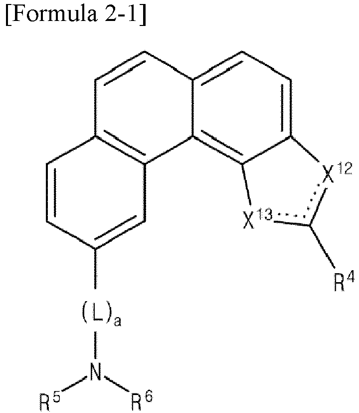 one of X12 and X13 is a nitrogen atom (N), and the other one of X12 and X13 is an oxygen atom (O) or a sulfur atom (S);each of R4, R5 and R6 is independently selected from the group consisting of an unsubstituted or substituted C6-C30 aryl group and an unsubstituted or substituted C3-C30 heteroaryl group; andL is selected from the group consisting of an unsubstituted or substituted C6-C30 arylene group and an unsubstituted or substituted C3-C30 heteroarylene group; anda is 0 or 1,wherein the third compound is represented by Formula 3-1:wherein in Formula 3-1:
 X is NR8, O or S,R8 is selected from the group consisting of an unsubstituted or substituted C1-C10 alkyl group, an unsubstituted or substituted C6-C30 aryl group and an unsubstituted or substituted C3-C30 heteroaryl group, andR7 is selected from the group consisting of an unsubstituted or substituted C6-C30 aryl group and an unsubstituted or substituted C3-C30 heteroaryl group.
 - The organic light emitting diode (D, D1, D2, D3 D4, D5) of claim 1, wherein Formula 1-1 is represented by Formula 1-2:

 wherein Y3 is BR2, CR2R3, C=O, SiR2R3, GeR2R3, PR2, P=O, O, S, SO2, Se, SeO2, Te, TeO2, or NRa, andwherein each of M, R,
- The organic light emitting diode (D, D1, D2, D3 D4, D5) of claim 1, wherein Formula 1-1 is represented by Formula 1-3:
 wherein Y4 is BR2, CR2R3, C=O, SiR2R3, GeR2R3, PR2, P=O, O, S, SO2, Se, SeO2, Te, TeO2, or NRa, andwherein each of M,
- The organic light emitting diode (D, D1, D2, D3 D4, D5) of claim 2, wherein Formula 1-2 is represented by Formula 1-4 or Formula 1-5:


wherein each of M, R,
- The organic light emitting diode (D, D1, D2, D3 D4, D5) of claim 3, wherein Formula 1-3 is represented by Formula 1-6 or Formula 1-7:


wherein each of M,
- The organic light emitting diode (D, D1, D2, D3 D4, D5) of claim 1, wherein Formula 1-1 is represented by one of Formula 1-8 to Formula 1-11:


 wherein each of X21 to X24, X34 to X38, X41 to X45 and X51 to X55 is independently CR1 or N,wherein each of Y3 and Y4 is independently BR2, CR2R3, C=O, SiR2R3, GeR2R3, PR2, P=O, O, S, SO2, Se, SeO2, Te or TeO2, or NRa,wherein each of R1 to R3 and Ra is same as defined in Formula 1-1,wherein each of R11 to R13 is independently selected from the group consisting of hydrogen, protium, deuterium, tritium, a halogen atom, a hydroxyl group, a cyano group, a nitro group, an amidino group, a hydrazine group, a hydrozone group, an unsubstituted or substituted C1-C20 alkyl group, an unsubstituted or substituted C2-C20 alkenyl group, an unsubstituted or substituted C2-C20 alkynyl group, an unsubstituted or substituted C1-C20 alkoxy group, an amino group, an unsubstituted or substituted C1-C20 alkyl amino group, an unsubstituted or substituted C1-C20 alkyl silyl group, a carboxyl group, a nitrile group, an isonitrile group, a sulfanyl group, a phosphino group, an unsubstituted or substituted C3-C30 alicyclic group, an unsubstituted or substituted C3-C30 hetero alicyclic group, an unsubstituted or substituted C6-C30 aromatic group and an unsubstituted or substituted C3-C30 hetero aromatic group,wherein m is an integer of 1 to 3, and n is an integer of 0 to 2, andwherein m+n is 3.
 - The organic light emitting diode (D, D1, D2, D3 D4, D5) of claim 1, wherein Formula 1-1 is represented by one of Formula 1-12 to Formula 1-15:


 wherein each of X21 to X24, X34 to X38, X41 to X45 and X51 to X55 is independently CR1 or N,wherein each of Y3 and Y4 is independently BR2, CR2R3, C=O, SiR2R3, GeR2R3, PR2, P=O, O, S, SO2, Se, SeO2, Te or TeO2, or NRa,wherein each of R1 to R3 and Ra is same as defined in Formula 1-1,wherein each of R61 to R64 is independently selected from the group consisting of hydrogen, protium, deuterium, tritium, a halogen atom, a hydroxyl group, a cyano group, a nitro group, an amidino group, a hydrazine group, a hydrozone group, an unsubstituted or substituted C1-C20 alkyl group, an unsubstituted or substituted C2-C20 alkenyl group, an unsubstituted or substituted C2-C20 alkynyl group, an unsubstituted or substituted C1-C20 alkoxy group, an amino group, an unsubstituted or substituted C1-C20 alkyl amino group, an unsubstituted or substituted C1-C20 alkyl silyl group, a carboxyl group, a nitrile group, an isonitrile group, a sulfanyl group, a phosphino group, an unsubstituted or substituted C3-C30 alicyclic group, an unsubstituted or substituted C3-C30 hetero alicyclic group, an unsubstituted or substituted C6-C30 aromatic group and an unsubstituted or substituted C3-C30 hetero aromatic group,wherein m is an integer of 1 to 3, and n is an integer of 0 to 2, andwherein m+n is 3.
 - The organic light emitting diode (D, D1, D2, D3 D4, D5) of claim 1, wherein Formula 1-1 is represented by one of Formula 1-16 to Formula 1-19:


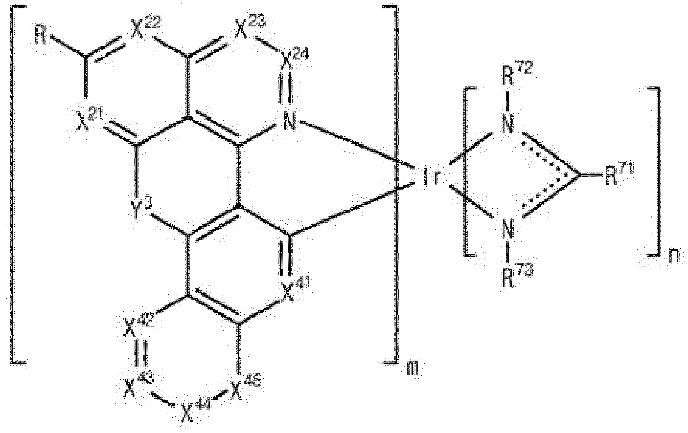


 wherein each of X21 to X24, X34 to X38, X41 to X45 and X51 to X55 is independently CR1 or N,wherein each of Y3 and Y4 is independently BR2, CR2R3, C=O, SiR2R3, GeR2R3, PR2, P=O, O, S, SO2, Se, SeO2, Te or TeO2, or NRa,wherein each of R1 to R3 and Ra is same as defined in Formula 1-1,wherein each of R71 to R73 is independently selected from the group consisting of hydrogen, protium, deuterium, tritium, a halogen atom, a hydroxyl group, a cyano group, a nitro group, an amidino group, a hydrazine group, a hydrozone group, an unsubstituted or substituted C1-C20 alkyl group, an unsubstituted or substituted C2-C20 alkenyl group, an unsubstituted or substituted C2-C20 alkynyl group, an unsubstituted or substituted C1-C20 alkoxy group, an amino group, an unsubstituted or substituted C1-C20 alkyl amino group, an unsubstituted or substituted C1-C20 alkyl silyl group, a carboxyl group, a nitrile group, an isonitrile group, a sulfanyl group, a phosphino group, an unsubstituted or substituted C3-C30 alicyclic group, an unsubstituted or substituted C3-C30 hetero alicyclic group, an unsubstituted or substituted C6-C30 aromatic group and an unsubstituted or substituted C3-C30 hetero aromatic group,wherein m is an integer of 1 to 3, and n is an integer of 0 to 2, andwherein m+n is 3.
 - The organic light emitting diode (D, D1, D2, D3 D4, D5) of claim 1, wherein Formula 1-1 is represented by one of Formula 1-20 to Formula 1-23:


 wherein each of X21 to X24, X34 to X38, X41 to X45 and X51 to X55 is independently CR1 or N,wherein each of Y3 and Y4 is independently BR2, CR2R3, C=O, SiR2R3, GeR2R3, PR2, P=O, O, S, SO2, Se, SeO2, Te or TeO2, or NRa,wherein each of R1 to R3 and Ra is same as defined in Formula 1-1,wherein each of R81 to R85 in Formulas 1-20 to 1-23 is independently selected from the group consisting of hydrogen, protium, deuterium, tritium, a halogen atom, a hydroxyl group, a cyano group, a nitro group, an amidino group, a hydrazine group, a hydrozone group, an unsubstituted or substituted C1-C20 alkyl group, an unsubstituted or substituted C2-C20 alkenyl group, an unsubstituted or substituted C2-C20 alkynyl group, an unsubstituted or substituted C1-C20 alkoxy group, an amino group, an unsubstituted or substituted C1-C20 alkyl amino group, an unsubstituted or substituted C1-C20 alkyl silyl group, a carboxyl group, a nitrile group, an isonitrile group, a sulfanyl group, a phosphino group, an unsubstituted or substituted C3-C30 alicyclic group, an unsubstituted or substituted C3-C30 hetero alicyclic group, an unsubstituted or substituted C6-C30 aromatic group and an unsubstituted or substituted C3-C30 hetero aromatic group,wherein m is an integer of 1 to 3, and n is an integer of 0 to 2, andwherein m+n is 3.
 - The organic light emitting diode (D, D1, D2, D3 D4, D5) of claim 1, wherein the first compound (232, 412, 512, 612, 722) is one of the following compounds:


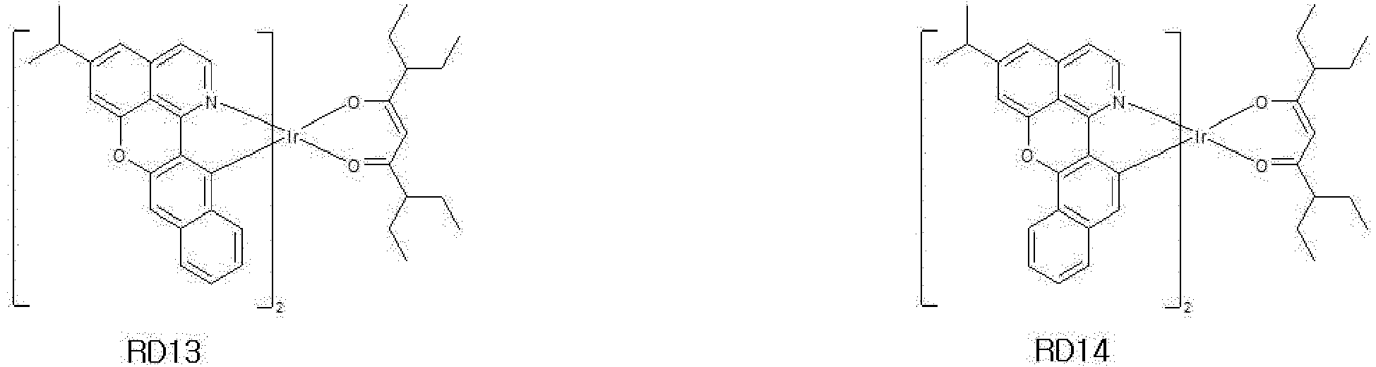


- The organic light emitting diode (D, D1, D2, D3 D4, D5) of any of claims 1 to 10, wherein the second compound (234, 414, 514, 614, 724) is one of the following compounds:


- The organic light emitting diode (D, D1, D2, D3 D4, D5) of any of claims 1 to 11, wherein Formula 3-1 is represented by Formula 3-2:
 X is NR2, O or S,R2 is selected from the group consisting of an unsubstituted or substituted C1-C10 alkyl group, an unsubstituted or substituted C6-C30 aryl group and an unsubstituted or substituted C3-C30 heteroaryl group, andR1 is selected from the group consisting of an unsubstituted or substituted C6-C30 aryl group and an unsubstituted or substituted C3-C30 heteroaryl group;or wherein Formula 3-1 is represented by Formula 3-3:
 X is NR2, O or S,R2 is selected from the group consisting of an unsubstituted or substituted C1-C10 alkyl group, an unsubstituted or substituted C6-C30 aryl group and an unsubstituted or substituted C3-C30 heteroaryl group, andR1 is selected from the group consisting of an unsubstituted or substituted C6-C30 aryl group and an unsubstituted or substituted C3-C30 heteroaryl group;or wherein the third compound (236, 416, 516, 616, 726) is one of the following compounds:


- The organic light emitting diode (D, D1, D2, D3 D4, D5) of any of claims 1 to 12, wherein each of a weight % of the second and third compounds (234, 236; 414, 416; 514, 516; 614, 616; 724, 726) is greater than a weight % of the first compound (232, 412, 512, 612, 722).
- The organic light emitting diode (D, D2) of any of claims 1 to 13, further comprising:a second emitting part (730) including a second red emitting material layer (740) and positioned between the first emitting part (710) and the second electrode (164); anda charge generation layer (750) positioned between the first and second emitting parts (710, 730),wherein, optionally, the second red emitting material layer (740) includes a fourth compound (742) represented by Formula 1-1, a fifth compound (744) represented by Formula 2-1 and a sixth compound (746) represented by Formula 3-1.
- The organic light emitting diode (D, D3, D4) of any of claims 1 to 13, further comprising:a second emitting part (440, 540) including a first blue emitting material layer (450, 550) and positioned between the first electrode (360) and the first emitting part (430, 530); anda first charge generation layer (480, 580) positioned between the first and second emitting parts (430, 440; 530, 540).
- The organic light emitting diode (D, D3, D4) of claim 15, further comprising:a third emitting part (460, 560) including a second blue emitting material layer (470, 570) and positioned between the first emitting part (430, 530) and the second electrode (364); anda second charge generation layer (490, 590) positioned between the first and third emitting parts (430, 460; 530, 560),wherein, optionally, the first emitting part (430, 530) further includes a green emitting material layer (420, 520) positioned between the first red emitting material layer (410, 520) and the second charge generation layer (490, 590),wherein, further optionally, the first emitting part (530) further includes a yellow-green emitting material layer (525) positioned between the first red emitting material layer (510) and the green emitting material layer (520).
- An organic light emitting device (100, 300), comprising:a substrate (110, 310);the organic light emitting diode (D, D1, D2, D3, D4, D5) of any of claims 1 to 16 positioned on the substrate (110, 310).
Applications Claiming Priority (1)
| Application Number | Priority Date | Filing Date | Title |
|---|---|---|---|
| KR1020210133077A KR102939666B1 (en) | 2021-10-07 | 2021-10-07 | Organic light emitting diode and organic light emitting device having the same |
Publications (2)
| Publication Number | Publication Date |
|---|---|
| EP4164363A1 true EP4164363A1 (en) | 2023-04-12 |
| EP4164363B1 EP4164363B1 (en) | 2024-06-12 |
Family
ID=83598490
Family Applications (1)
| Application Number | Title | Priority Date | Filing Date |
|---|---|---|---|
| EP22199762.0A Active EP4164363B1 (en) | 2021-10-07 | 2022-10-05 | Organic light emitting diode and organic light emitting device including the same |
Country Status (4)
| Country | Link |
|---|---|
| US (1) | US12598907B2 (en) |
| EP (1) | EP4164363B1 (en) |
| KR (1) | KR102939666B1 (en) |
| CN (1) | CN115955896A (en) |
Families Citing this family (4)
| Publication number | Priority date | Publication date | Assignee | Title |
|---|---|---|---|---|
| KR20230049946A (en) * | 2021-10-07 | 2023-04-14 | 엘지디스플레이 주식회사 | Organic light emitting diode and organic light emitting device having the same |
| KR20230049945A (en) * | 2021-10-07 | 2023-04-14 | 엘지디스플레이 주식회사 | Organic light emitting diode and organic light emitting device having the same |
| KR20230049951A (en) * | 2021-10-07 | 2023-04-14 | 엘지디스플레이 주식회사 | Organic light emitting diode and organic light emitting device having the same |
| CN118324817B (en) * | 2023-05-11 | 2025-07-18 | 广东阿格蕾雅光电材料有限公司 | Iridium complex and organic electroluminescent device |
Citations (3)
| Publication number | Priority date | Publication date | Assignee | Title |
|---|---|---|---|---|
| US20160336518A1 (en) * | 2014-08-20 | 2016-11-17 | Lg Chem, Ltd. | Organic light-emitting device |
| CN110790797A (en) * | 2019-11-08 | 2020-02-14 | 吉林奥来德光电材料股份有限公司 | Organic phosphorus luminescent material and preparation method and application thereof |
| US20210296595A1 (en) * | 2020-02-27 | 2021-09-23 | Rohm And Haas Electronic Materials Korea Ltd. | Organic electroluminescent compound, a plurality of host materials, and organic electroluminescent device comprising the same |
Family Cites Families (10)
| Publication number | Priority date | Publication date | Assignee | Title |
|---|---|---|---|---|
| KR101477614B1 (en) * | 2010-09-17 | 2014-12-31 | 롬엔드하스전자재료코리아유한회사 | Novel organic electroluminescent compounds and organic electroluminescent device using the same |
| KR102102580B1 (en) * | 2012-07-20 | 2020-04-22 | 롬엔드하스전자재료코리아유한회사 | Organic Electroluminescence Device |
| CN106749341B (en) * | 2017-01-18 | 2018-11-27 | 江西冠能光电材料有限公司 | Balancing charge injects organic semiconductor and its Organic Light Emitting Diode application |
| CN106800555B (en) * | 2017-01-19 | 2018-10-30 | 江西冠能光电材料有限公司 | A kind of organic semiconductor material of main part and its Organic Light Emitting Diode application |
| WO2018155942A1 (en) * | 2017-02-27 | 2018-08-30 | Rohm And Haas Electronic Materials Korea Ltd. | A plurality of host materials and organic electroluminescent device comprising the same |
| WO2020027506A1 (en) * | 2018-07-30 | 2020-02-06 | Rohm And Haas Electronic Materials Korea Ltd. | A plurality of host materials and organic electroluminescent device comprising the same |
| WO2020045976A1 (en) * | 2018-08-29 | 2020-03-05 | Rohm And Haas Electronic Materials Korea Ltd. | A plurality of host materials and organic electroluminescent device comprising the same |
| CN112979558A (en) * | 2019-12-16 | 2021-06-18 | 罗门哈斯电子材料韩国有限公司 | Organic electroluminescent compounds, various host materials and organic electroluminescent device comprising the same |
| KR20210082888A (en) * | 2019-12-26 | 2021-07-06 | 롬엔드하스전자재료코리아유한회사 | A plurality of host materials and organic electroluminescent device comprising the same |
| US11157235B2 (en) | 2020-03-10 | 2021-10-26 | Aptiv Technologies Limited | System and method for veryifying audible and/or visual notifications |
-
2021
- 2021-10-07 KR KR1020210133077A patent/KR102939666B1/en active Active
-
2022
- 2022-09-30 CN CN202211216228.5A patent/CN115955896A/en active Pending
- 2022-10-03 US US17/958,698 patent/US12598907B2/en active Active
- 2022-10-05 EP EP22199762.0A patent/EP4164363B1/en active Active
Patent Citations (3)
| Publication number | Priority date | Publication date | Assignee | Title |
|---|---|---|---|---|
| US20160336518A1 (en) * | 2014-08-20 | 2016-11-17 | Lg Chem, Ltd. | Organic light-emitting device |
| CN110790797A (en) * | 2019-11-08 | 2020-02-14 | 吉林奥来德光电材料股份有限公司 | Organic phosphorus luminescent material and preparation method and application thereof |
| US20210296595A1 (en) * | 2020-02-27 | 2021-09-23 | Rohm And Haas Electronic Materials Korea Ltd. | Organic electroluminescent compound, a plurality of host materials, and organic electroluminescent device comprising the same |
Also Published As
| Publication number | Publication date |
|---|---|
| KR20230049947A (en) | 2023-04-14 |
| EP4164363B1 (en) | 2024-06-12 |
| KR102939666B1 (en) | 2026-03-13 |
| CN115955896A (en) | 2023-04-11 |
| US20230148324A1 (en) | 2023-05-11 |
| US12598907B2 (en) | 2026-04-07 |
Similar Documents
| Publication | Publication Date | Title |
|---|---|---|
| EP4164363B1 (en) | Organic light emitting diode and organic light emitting device including the same | |
| EP4164365B1 (en) | Organic light emitting diode and organic light emitting device including the same | |
| KR102356399B1 (en) | Light-emitting element, light-emitting device, lighting device, and electronic device | |
| EP4164366B1 (en) | Organic light emitting diode and organic light emitting device including the same | |
| JP2022110006A (en) | organic compounds, light-emitting elements, light-emitting devices, electronic devices and lighting devices | |
| EP4164364B1 (en) | Organic light emitting diode and organic light emitting device including the same | |
| EP4648598A1 (en) | Organic light emitting diode and organic light emitting device having the same | |
| JP7589548B2 (en) | Light-emitting element material containing pyrromethene boron complex, light-emitting element, display device, and lighting device | |
| US20140124764A1 (en) | Heterocyclic compound, light-emitting element, light-emitting device, electronic device, and lighting device | |
| US20230123928A1 (en) | Organic light emitting diode and organic light emitting device including the same | |
| US12581847B2 (en) | Organic light emitting diode and organic light emitting device including the same | |
| US20230132589A1 (en) | Organic light emitting diode and organic light emitting device including the same | |
| US12610731B2 (en) | Organic light emitting diode and organic light emitting device including the same | |
| US20230121109A1 (en) | Organic light emitting diode and organic light emitting device including the same | |
| EP4389851A1 (en) | Organic compound, organic light emitting diode and organic light emitting device having the compound |
Legal Events
| Date | Code | Title | Description |
|---|---|---|---|
| PUAI | Public reference made under article 153(3) epc to a published international application that has entered the european phase |
Free format text: ORIGINAL CODE: 0009012 |
|
| STAA | Information on the status of an ep patent application or granted ep patent |
Free format text: STATUS: REQUEST FOR EXAMINATION WAS MADE |
|
| 17P | Request for examination filed |
Effective date: 20221005 |
|
| AK | Designated contracting states |
Kind code of ref document: A1 Designated state(s): AL AT BE BG CH CY CZ DE DK EE ES FI FR GB GR HR HU IE IS IT LI LT LU LV MC ME MK MT NL NO PL PT RO RS SE SI SK SM TR |
|
| RBV | Designated contracting states (corrected) |
Designated state(s): AL AT BE BG CH CY CZ DE DK EE ES FI FR GB GR HR HU IE IS IT LI LT LU LV MC ME MK MT NL NO PL PT RO RS SE SI SK SM TR |
|
| GRAP | Despatch of communication of intention to grant a patent |
Free format text: ORIGINAL CODE: EPIDOSNIGR1 |
|
| STAA | Information on the status of an ep patent application or granted ep patent |
Free format text: STATUS: GRANT OF PATENT IS INTENDED |
|
| RIC1 | Information provided on ipc code assigned before grant |
Ipc: H10K 101/10 20230101ALN20240131BHEP Ipc: H10K 50/13 20230101ALN20240131BHEP Ipc: H10K 50/11 20230101ALI20240131BHEP Ipc: H10K 85/60 20230101ALI20240131BHEP Ipc: H10K 85/30 20230101AFI20240131BHEP |
|
| INTG | Intention to grant announced |
Effective date: 20240213 |
|
| GRAS | Grant fee paid |
Free format text: ORIGINAL CODE: EPIDOSNIGR3 |
|
| GRAA | (expected) grant |
Free format text: ORIGINAL CODE: 0009210 |
|
| STAA | Information on the status of an ep patent application or granted ep patent |
Free format text: STATUS: THE PATENT HAS BEEN GRANTED |
|
| AK | Designated contracting states |
Kind code of ref document: B1 Designated state(s): AL AT BE BG CH CY CZ DE DK EE ES FI FR GB GR HR HU IE IS IT LI LT LU LV MC ME MK MT NL NO PL PT RO RS SE SI SK SM TR |
|
| REG | Reference to a national code |
Ref country code: GB Ref legal event code: FG4D |
|
| REG | Reference to a national code |
Ref country code: CH Ref legal event code: EP |
|
| REG | Reference to a national code |
Ref country code: DE Ref legal event code: R096 Ref document number: 602022003921 Country of ref document: DE |
|
| REG | Reference to a national code |
Ref country code: IE Ref legal event code: FG4D |
|
| PG25 | Lapsed in a contracting state [announced via postgrant information from national office to epo] |
Ref country code: BG Free format text: LAPSE BECAUSE OF FAILURE TO SUBMIT A TRANSLATION OF THE DESCRIPTION OR TO PAY THE FEE WITHIN THE PRESCRIBED TIME-LIMIT Effective date: 20240612 |
|
| PG25 | Lapsed in a contracting state [announced via postgrant information from national office to epo] |
Ref country code: FI Free format text: LAPSE BECAUSE OF FAILURE TO SUBMIT A TRANSLATION OF THE DESCRIPTION OR TO PAY THE FEE WITHIN THE PRESCRIBED TIME-LIMIT Effective date: 20240612 Ref country code: HR Free format text: LAPSE BECAUSE OF FAILURE TO SUBMIT A TRANSLATION OF THE DESCRIPTION OR TO PAY THE FEE WITHIN THE PRESCRIBED TIME-LIMIT Effective date: 20240612 |
|
| REG | Reference to a national code |
Ref country code: LT Ref legal event code: MG9D |
|
| PG25 | Lapsed in a contracting state [announced via postgrant information from national office to epo] |
Ref country code: GR Free format text: LAPSE BECAUSE OF FAILURE TO SUBMIT A TRANSLATION OF THE DESCRIPTION OR TO PAY THE FEE WITHIN THE PRESCRIBED TIME-LIMIT Effective date: 20240913 |
|
| REG | Reference to a national code |
Ref country code: NL Ref legal event code: MP Effective date: 20240612 |
|
| PG25 | Lapsed in a contracting state [announced via postgrant information from national office to epo] |
Ref country code: ES Free format text: LAPSE BECAUSE OF FAILURE TO SUBMIT A TRANSLATION OF THE DESCRIPTION OR TO PAY THE FEE WITHIN THE PRESCRIBED TIME-LIMIT Effective date: 20240612 |
|
| PG25 | Lapsed in a contracting state [announced via postgrant information from national office to epo] |
Ref country code: LV Free format text: LAPSE BECAUSE OF FAILURE TO SUBMIT A TRANSLATION OF THE DESCRIPTION OR TO PAY THE FEE WITHIN THE PRESCRIBED TIME-LIMIT Effective date: 20240612 |
|
| PG25 | Lapsed in a contracting state [announced via postgrant information from national office to epo] |
Ref country code: NO Free format text: LAPSE BECAUSE OF FAILURE TO SUBMIT A TRANSLATION OF THE DESCRIPTION OR TO PAY THE FEE WITHIN THE PRESCRIBED TIME-LIMIT Effective date: 20240912 Ref country code: LV Free format text: LAPSE BECAUSE OF FAILURE TO SUBMIT A TRANSLATION OF THE DESCRIPTION OR TO PAY THE FEE WITHIN THE PRESCRIBED TIME-LIMIT Effective date: 20240612 Ref country code: HR Free format text: LAPSE BECAUSE OF FAILURE TO SUBMIT A TRANSLATION OF THE DESCRIPTION OR TO PAY THE FEE WITHIN THE PRESCRIBED TIME-LIMIT Effective date: 20240612 Ref country code: GR Free format text: LAPSE BECAUSE OF FAILURE TO SUBMIT A TRANSLATION OF THE DESCRIPTION OR TO PAY THE FEE WITHIN THE PRESCRIBED TIME-LIMIT Effective date: 20240913 Ref country code: FI Free format text: LAPSE BECAUSE OF FAILURE TO SUBMIT A TRANSLATION OF THE DESCRIPTION OR TO PAY THE FEE WITHIN THE PRESCRIBED TIME-LIMIT Effective date: 20240612 Ref country code: ES Free format text: LAPSE BECAUSE OF FAILURE TO SUBMIT A TRANSLATION OF THE DESCRIPTION OR TO PAY THE FEE WITHIN THE PRESCRIBED TIME-LIMIT Effective date: 20240612 Ref country code: BG Free format text: LAPSE BECAUSE OF FAILURE TO SUBMIT A TRANSLATION OF THE DESCRIPTION OR TO PAY THE FEE WITHIN THE PRESCRIBED TIME-LIMIT Effective date: 20240612 Ref country code: RS Free format text: LAPSE BECAUSE OF FAILURE TO SUBMIT A TRANSLATION OF THE DESCRIPTION OR TO PAY THE FEE WITHIN THE PRESCRIBED TIME-LIMIT Effective date: 20240912 |
|
| PG25 | Lapsed in a contracting state [announced via postgrant information from national office to epo] |
Ref country code: NL Free format text: LAPSE BECAUSE OF FAILURE TO SUBMIT A TRANSLATION OF THE DESCRIPTION OR TO PAY THE FEE WITHIN THE PRESCRIBED TIME-LIMIT Effective date: 20240612 |
|
| REG | Reference to a national code |
Ref country code: AT Ref legal event code: MK05 Ref document number: 1695301 Country of ref document: AT Kind code of ref document: T Effective date: 20240612 |
|
| PG25 | Lapsed in a contracting state [announced via postgrant information from national office to epo] |
Ref country code: NL Free format text: LAPSE BECAUSE OF FAILURE TO SUBMIT A TRANSLATION OF THE DESCRIPTION OR TO PAY THE FEE WITHIN THE PRESCRIBED TIME-LIMIT Effective date: 20240612 |
|
| PG25 | Lapsed in a contracting state [announced via postgrant information from national office to epo] |
Ref country code: PT Free format text: LAPSE BECAUSE OF FAILURE TO SUBMIT A TRANSLATION OF THE DESCRIPTION OR TO PAY THE FEE WITHIN THE PRESCRIBED TIME-LIMIT Effective date: 20241014 |
|
| PG25 | Lapsed in a contracting state [announced via postgrant information from national office to epo] |
Ref country code: PT Free format text: LAPSE BECAUSE OF FAILURE TO SUBMIT A TRANSLATION OF THE DESCRIPTION OR TO PAY THE FEE WITHIN THE PRESCRIBED TIME-LIMIT Effective date: 20241014 |
|
| PG25 | Lapsed in a contracting state [announced via postgrant information from national office to epo] |
Ref country code: PL Free format text: LAPSE BECAUSE OF FAILURE TO SUBMIT A TRANSLATION OF THE DESCRIPTION OR TO PAY THE FEE WITHIN THE PRESCRIBED TIME-LIMIT Effective date: 20240612 |
|
| PG25 | Lapsed in a contracting state [announced via postgrant information from national office to epo] |
Ref country code: EE Free format text: LAPSE BECAUSE OF FAILURE TO SUBMIT A TRANSLATION OF THE DESCRIPTION OR TO PAY THE FEE WITHIN THE PRESCRIBED TIME-LIMIT Effective date: 20240612 |
|
| PG25 | Lapsed in a contracting state [announced via postgrant information from national office to epo] |
Ref country code: AT Free format text: LAPSE BECAUSE OF FAILURE TO SUBMIT A TRANSLATION OF THE DESCRIPTION OR TO PAY THE FEE WITHIN THE PRESCRIBED TIME-LIMIT Effective date: 20240612 Ref country code: IS Free format text: LAPSE BECAUSE OF FAILURE TO SUBMIT A TRANSLATION OF THE DESCRIPTION OR TO PAY THE FEE WITHIN THE PRESCRIBED TIME-LIMIT Effective date: 20241012 |
|
| PG25 | Lapsed in a contracting state [announced via postgrant information from national office to epo] |
Ref country code: CZ Free format text: LAPSE BECAUSE OF FAILURE TO SUBMIT A TRANSLATION OF THE DESCRIPTION OR TO PAY THE FEE WITHIN THE PRESCRIBED TIME-LIMIT Effective date: 20240612 |
|
| PG25 | Lapsed in a contracting state [announced via postgrant information from national office to epo] |
Ref country code: RO Free format text: LAPSE BECAUSE OF FAILURE TO SUBMIT A TRANSLATION OF THE DESCRIPTION OR TO PAY THE FEE WITHIN THE PRESCRIBED TIME-LIMIT Effective date: 20240612 Ref country code: SK Free format text: LAPSE BECAUSE OF FAILURE TO SUBMIT A TRANSLATION OF THE DESCRIPTION OR TO PAY THE FEE WITHIN THE PRESCRIBED TIME-LIMIT Effective date: 20240612 |
|
| PG25 | Lapsed in a contracting state [announced via postgrant information from national office to epo] |
Ref country code: SM Free format text: LAPSE BECAUSE OF FAILURE TO SUBMIT A TRANSLATION OF THE DESCRIPTION OR TO PAY THE FEE WITHIN THE PRESCRIBED TIME-LIMIT Effective date: 20240612 |
|
| PG25 | Lapsed in a contracting state [announced via postgrant information from national office to epo] |
Ref country code: SM Free format text: LAPSE BECAUSE OF FAILURE TO SUBMIT A TRANSLATION OF THE DESCRIPTION OR TO PAY THE FEE WITHIN THE PRESCRIBED TIME-LIMIT Effective date: 20240612 Ref country code: SK Free format text: LAPSE BECAUSE OF FAILURE TO SUBMIT A TRANSLATION OF THE DESCRIPTION OR TO PAY THE FEE WITHIN THE PRESCRIBED TIME-LIMIT Effective date: 20240612 Ref country code: RO Free format text: LAPSE BECAUSE OF FAILURE TO SUBMIT A TRANSLATION OF THE DESCRIPTION OR TO PAY THE FEE WITHIN THE PRESCRIBED TIME-LIMIT Effective date: 20240612 Ref country code: PL Free format text: LAPSE BECAUSE OF FAILURE TO SUBMIT A TRANSLATION OF THE DESCRIPTION OR TO PAY THE FEE WITHIN THE PRESCRIBED TIME-LIMIT Effective date: 20240612 Ref country code: IS Free format text: LAPSE BECAUSE OF FAILURE TO SUBMIT A TRANSLATION OF THE DESCRIPTION OR TO PAY THE FEE WITHIN THE PRESCRIBED TIME-LIMIT Effective date: 20241012 Ref country code: EE Free format text: LAPSE BECAUSE OF FAILURE TO SUBMIT A TRANSLATION OF THE DESCRIPTION OR TO PAY THE FEE WITHIN THE PRESCRIBED TIME-LIMIT Effective date: 20240612 Ref country code: CZ Free format text: LAPSE BECAUSE OF FAILURE TO SUBMIT A TRANSLATION OF THE DESCRIPTION OR TO PAY THE FEE WITHIN THE PRESCRIBED TIME-LIMIT Effective date: 20240612 Ref country code: AT Free format text: LAPSE BECAUSE OF FAILURE TO SUBMIT A TRANSLATION OF THE DESCRIPTION OR TO PAY THE FEE WITHIN THE PRESCRIBED TIME-LIMIT Effective date: 20240612 |
|
| PG25 | Lapsed in a contracting state [announced via postgrant information from national office to epo] |
Ref country code: IT Free format text: LAPSE BECAUSE OF FAILURE TO SUBMIT A TRANSLATION OF THE DESCRIPTION OR TO PAY THE FEE WITHIN THE PRESCRIBED TIME-LIMIT Effective date: 20240612 |
|
| REG | Reference to a national code |
Ref country code: DE Ref legal event code: R097 Ref document number: 602022003921 Country of ref document: DE |
|
| PG25 | Lapsed in a contracting state [announced via postgrant information from national office to epo] |
Ref country code: DK Free format text: LAPSE BECAUSE OF FAILURE TO SUBMIT A TRANSLATION OF THE DESCRIPTION OR TO PAY THE FEE WITHIN THE PRESCRIBED TIME-LIMIT Effective date: 20240612 |
|
| PLBE | No opposition filed within time limit |
Free format text: ORIGINAL CODE: 0009261 |
|
| STAA | Information on the status of an ep patent application or granted ep patent |
Free format text: STATUS: NO OPPOSITION FILED WITHIN TIME LIMIT |
|
| 26N | No opposition filed |
Effective date: 20250313 |
|
| PG25 | Lapsed in a contracting state [announced via postgrant information from national office to epo] |
Ref country code: MC Free format text: LAPSE BECAUSE OF FAILURE TO SUBMIT A TRANSLATION OF THE DESCRIPTION OR TO PAY THE FEE WITHIN THE PRESCRIBED TIME-LIMIT Effective date: 20240612 |
|
| PG25 | Lapsed in a contracting state [announced via postgrant information from national office to epo] |
Ref country code: BE Free format text: LAPSE BECAUSE OF NON-PAYMENT OF DUE FEES Effective date: 20241031 Ref country code: LU Free format text: LAPSE BECAUSE OF NON-PAYMENT OF DUE FEES Effective date: 20241005 |
|
| REG | Reference to a national code |
Ref country code: BE Ref legal event code: MM Effective date: 20241031 |
|
| PG25 | Lapsed in a contracting state [announced via postgrant information from national office to epo] |
Ref country code: SE Free format text: LAPSE BECAUSE OF FAILURE TO SUBMIT A TRANSLATION OF THE DESCRIPTION OR TO PAY THE FEE WITHIN THE PRESCRIBED TIME-LIMIT Effective date: 20240612 |
|
| PGFP | Annual fee paid to national office [announced via postgrant information from national office to epo] |
Ref country code: FR Payment date: 20250821 Year of fee payment: 4 |
|
| PG25 | Lapsed in a contracting state [announced via postgrant information from national office to epo] |
Ref country code: IE Free format text: LAPSE BECAUSE OF NON-PAYMENT OF DUE FEES Effective date: 20241005 |
|
| PGFP | Annual fee paid to national office [announced via postgrant information from national office to epo] |
Ref country code: DE Payment date: 20250820 Year of fee payment: 4 |
|
| PG25 | Lapsed in a contracting state [announced via postgrant information from national office to epo] |
Ref country code: CY Free format text: LAPSE BECAUSE OF FAILURE TO SUBMIT A TRANSLATION OF THE DESCRIPTION OR TO PAY THE FEE WITHIN THE PRESCRIBED TIME-LIMIT; INVALID AB INITIO Effective date: 20221005 |
|
| PG25 | Lapsed in a contracting state [announced via postgrant information from national office to epo] |
Ref country code: HU Free format text: LAPSE BECAUSE OF FAILURE TO SUBMIT A TRANSLATION OF THE DESCRIPTION OR TO PAY THE FEE WITHIN THE PRESCRIBED TIME-LIMIT; INVALID AB INITIO Effective date: 20221005 |