EP4164287A1 - Mode switching method, terminal, and network side device - Google Patents
Mode switching method, terminal, and network side device Download PDFInfo
- Publication number
- EP4164287A1 EP4164287A1 EP21822607.4A EP21822607A EP4164287A1 EP 4164287 A1 EP4164287 A1 EP 4164287A1 EP 21822607 A EP21822607 A EP 21822607A EP 4164287 A1 EP4164287 A1 EP 4164287A1
- Authority
- EP
- European Patent Office
- Prior art keywords
- multicast
- air interface
- interface resource
- side device
- mode switching
- Prior art date
- Legal status (The legal status is an assumption and is not a legal conclusion. Google has not performed a legal analysis and makes no representation as to the accuracy of the status listed.)
- Pending
Links
Images




Classifications
-
- H—ELECTRICITY
- H04—ELECTRIC COMMUNICATION TECHNIQUE
- H04W—WIRELESS COMMUNICATION NETWORKS
- H04W28/00—Network traffic management; Network resource management
- H04W28/02—Traffic management, e.g. flow control or congestion control
- H04W28/0205—Traffic management, e.g. flow control or congestion control at the air interface
-
- H—ELECTRICITY
- H04—ELECTRIC COMMUNICATION TECHNIQUE
- H04W—WIRELESS COMMUNICATION NETWORKS
- H04W28/00—Network traffic management; Network resource management
- H04W28/02—Traffic management, e.g. flow control or congestion control
- H04W28/0268—Traffic management, e.g. flow control or congestion control using specific QoS parameters for wireless networks, e.g. QoS class identifier [QCI] or guaranteed bit rate [GBR]
-
- H—ELECTRICITY
- H04—ELECTRIC COMMUNICATION TECHNIQUE
- H04W—WIRELESS COMMUNICATION NETWORKS
- H04W28/00—Network traffic management; Network resource management
- H04W28/16—Central resource management; Negotiation of resources or communication parameters, e.g. negotiating bandwidth or QoS [Quality of Service]
- H04W28/26—Resource reservation
-
- H—ELECTRICITY
- H04—ELECTRIC COMMUNICATION TECHNIQUE
- H04W—WIRELESS COMMUNICATION NETWORKS
- H04W4/00—Services specially adapted for wireless communication networks; Facilities therefor
- H04W4/06—Selective distribution of broadcast services, e.g. multimedia broadcast multicast service [MBMS]; Services to user groups; One-way selective calling services
-
- H—ELECTRICITY
- H04—ELECTRIC COMMUNICATION TECHNIQUE
- H04W—WIRELESS COMMUNICATION NETWORKS
- H04W76/00—Connection management
- H04W76/40—Connection management for selective distribution or broadcast
-
- H—ELECTRICITY
- H04—ELECTRIC COMMUNICATION TECHNIQUE
- H04W—WIRELESS COMMUNICATION NETWORKS
- H04W88/00—Devices specially adapted for wireless communication networks, e.g. terminals, base stations or access point devices
- H04W88/02—Terminal devices
-
- H—ELECTRICITY
- H04—ELECTRIC COMMUNICATION TECHNIQUE
- H04W—WIRELESS COMMUNICATION NETWORKS
- H04W88/00—Devices specially adapted for wireless communication networks, e.g. terminals, base stations or access point devices
- H04W88/02—Terminal devices
- H04W88/06—Terminal devices adapted for operation in multiple networks or having at least two operational modes, e.g. multi-mode terminals
-
- H—ELECTRICITY
- H04—ELECTRIC COMMUNICATION TECHNIQUE
- H04W—WIRELESS COMMUNICATION NETWORKS
- H04W72/00—Local resource management
- H04W72/30—Resource management for broadcast services
-
- H—ELECTRICITY
- H04—ELECTRIC COMMUNICATION TECHNIQUE
- H04W—WIRELESS COMMUNICATION NETWORKS
- H04W76/00—Connection management
- H04W76/10—Connection setup
- H04W76/12—Setup of transport tunnels
Definitions
- This application pertains to the field of communications technologies, and specifically relates to a mode switching method, a terminal, and a network-side device.
- a terminal may establish a protocol data unit (Protocol Data Unit, PDU) session (Session) to a data network (Data Network, DN) network element through a user plane function (User Plane Function, UPF) network element, and the PDU session provides PDU connectivity service between the terminal and the DN network element.
- PDU Protocol Data Unit
- DN data network
- UPF User Plane Function
- the terminal For a terminal using a point-to-point PDU session mode to receive multicast traffic to switch to a target network-side device supporting point-to-multipoint multicast, the terminal has to use a PDU session switching procedure to first switch the PDU session to the target network-side device. If the terminal wants to use the more efficient multicast data transmission mode, a mode switching has to be initiated by the terminal or the target network-side device so as to switch to the point-to-multipoint multicast transmission mode.
- the terminal needs to first switch the PDU session to the target network-side device by using the PDU session switching procedure, and then the terminal or the target network-side device initiates mode switching so as to switch to the point-to-multipoint multicast transmission mode.
- mode switching features relatively low switching efficiency.
- the purpose of embodiments of this application is to provide a mode switching method, a terminal, and a network-side device, so as to resolve a problem of low switching efficiency of mode switching.
- a mode switching method is provided, applied to a target network-side device, and the method includes: reserving a multicast air interface resource in a case that multicast quality of service QoS information is received from a multicast broadcast network function MB NF, where the multicast air interface resource is used for a terminal to receive multicast service data in a switched-to target mode, and the multicast QoS information corresponds to the multicast service data; and sending the multicast air interface resource to a source network-side device or the MB NF.
- a mode switching method is provided, applied to an MB NF, and the method includes: sending multicast QoS information to a target network-side device, where the multicast QoS information is used for the target network-side device to reserve a multicast air interface resource, the multicast air interface resource is used for a terminal to receive multicast service data in a switched-to target mode, and the multicast QoS information corresponds to the multicast service data.
- a mode switching method applied to a source network-side device, and the method includes: receiving a multicast air interface resource, where the multicast air interface resource is reserved by a target network-side device in a case that multicast QoS information is received from an MB NF, the multicast air interface resource is used for a terminal to receive multicast service data in a switched-to target mode, and the multicast QoS information corresponds to the multicast service data.
- a mode switching method applied to a terminal, and the method includes: receiving a multicast air interface resource, where the multicast air interface resource is reserved by a target network-side device in a case that multicast QoS information is received from an MB NF, the multicast air interface resource is used for the terminal to receive multicast service data in a switched-to target mode, and the multicast QoS information corresponds to the multicast service data.
- a mode switching apparatus includes: a resource reservation module, configured to reserve a multicast air interface resource in a case that multicast quality of service QoS information is received from a multicast broadcast network function MB NF, where the multicast air interface resource is used for a terminal to receive multicast service data in a switched-to target mode, and the multicast QoS information corresponds to the multicast service data; and a sending module, configured to send the multicast air interface resource to a source network-side device or the MB NF.
- a mode switching apparatus includes: a sending module, configured to send multicast QoS information to a target network-side device, where the multicast QoS information is used for the target network-side device to reserve a multicast air interface resource, the multicast air interface resource is used for a terminal to receive multicast service data in a switched-to target mode, and the multicast QoS information corresponds to the multicast service data.
- a mode switching apparatus includes: a receiving module, configured to receive a multicast air interface resource, where the multicast air interface resource is reserved by a target network-side device in a case that multicast QoS information is received from an MB NF, the multicast air interface resource is used for a terminal to receive multicast service data in a switched-to target mode, and the multicast QoS information corresponds to the multicast service data.
- a mode switching apparatus includes: a receiving module, configured to receive a multicast air interface resource, where the multicast air interface resource is reserved by a target network-side device in a case that multicast QoS information is received from an MB NF, the multicast air interface resource is used for the apparatus to receive multicast service data in a switched-to target mode, and the multicast QoS information corresponds to the multicast service data.
- a terminal includes a processor, a memory, and a program or instructions stored in the memory and capable of running on the processor, and when the program or instructions are executed by the processor, the method according to the fourth aspect is implemented.
- a network-side device includes a processor, a memory, and a program or instructions stored in the memory and capable of running on the processor, and when the program or instructions are executed by the processor, the method according to the first aspect, the second aspect, or the third aspect is implemented.
- a readable storage medium stores a program or instructions.
- the program or instructions are executed by a processor, the method according to the first aspect, the second aspect, the third aspect, or the fourth aspect is implemented.
- a chip is provided, where the chip includes a processor and a communications interface, the communications interface is coupled to the processor, and the processor is configured to run a program or instructions to implement the method according to the first aspect, the second aspect, the third aspect, or the fourth aspect.
- the target network-side device reserves the multicast air interface resource, and sends the multicast air interface resource to the source network-side device or the MB NF, so that the terminal can switch from a PDU session mode to the target mode and receives the multicast service data by using the multicast air interface resource, thereby improving switching efficiency of mode switching.
- first and second are intended to distinguish between similar objects but do not necessarily indicate a specific order or sequence. It should be understood that the data used in this way is interchangeable in appropriate circumstances so that the embodiments of this application can be implemented in other orders than the order illustrated or described herein, and “first” and “second” are usually for distinguishing same-type objects but not limiting the number of objects, for example, a first object may be one or multiple.
- first and second are usually for distinguishing same-type objects but not limiting the number of objects, for example, a first object may be one or multiple.
- “and/or” in this specification and claims indicates at least one of connected objects, and the symbol “/" generally indicates that the associated objects are in an "or” relationship.
- LTE Long Term Evolution
- LTE-Advanced LTE-Advanced
- LTE-A LTE-Advanced
- CDMA code division multiple access
- TDMA time division multiple access
- FDMA frequency division multiple access
- OFDMA Orthogonal Frequency Division Multiple Access
- SC-FDMA single-carrier Frequency-Division Multiple Access
- system and “network” in the embodiments of this application are usually used interchangeably. Techniques described herein may be used in the aforementioned systems and radio technologies, and may also be used in other systems and radio technologies. However, in the following descriptions, a new radio (New Radio, NR) system is described for an illustration purpose, and NR terms are used in most of the following descriptions, although these technologies may also be applied to other applications than the NR system application, for example, the sixth generation (6 th Generation, 6G) communications system.
- NR New Radio
- FIG. 1 is a block diagram of a wireless communications system to which the embodiments of this application are applicable.
- the wireless communications system includes a terminal 11 and a network-side device 12.
- the terminal 11 may also be referred to as a terminal device or a user terminal (User Equipment, UE), and the terminal 11 may be a terminal-side device, such as a mobile phone, a tablet computer (Tablet Personal Computer), a laptop computer (Laptop Computer) or a notebook computer, a personal digital assistant (Personal Digital Assistant, PDA), a palmtop computer, a netbook, an ultra-mobile personal computer (ultra-mobile personal computer, UMPC), a mobile Internet device (Mobile Internet Device, MID), a wearable device (Wearable Device) or an in-vehicle device (VUE), or a pedestrian terminal (PUE).
- a terminal device such as a mobile phone, a tablet computer (Tablet Personal Computer), a laptop computer (Laptop Computer) or a notebook computer, a personal digital assistant
- the wearable device includes: a wrist band, earphones, glasses, or the like. It should be noted that a specific type of the terminal 11 is not limited in the embodiments of this application.
- the network-side device 12 may be a base station or a core network.
- the base station may be referred to as a NodeB, an evolved NodeB, an access point, a base transceiver station (Base Transceiver Station, BTS), a radio base station, a radio transceiver, a basic service set (Basic Service Set, BSS), an extended service set (Extended Service Set, ESS), a home NodeB, a home evolved NodeB, a WLAN access point, a Wi-Fi node, a transmission reception point (Transmitting Receiving Point, TRP), or another appropriate term in the art.
- BTS Base Transceiver Station
- BSS Basic Service Set
- Extended Service Set Extended Service Set
- ESS extended service set
- a home NodeB a home evolved NodeB
- WLAN access point a Wi-Fi node
- TRP Transmission Receiving Point
- an embodiment of this application provides a mode switching method 200, and the method may be executed by a target network-side device.
- the method may be executed by software or hardware installed in the target network-side device, and the method 200 includes the following steps.
- S202 Reserve a multicast air interface resource in a case that multicast quality of service (Quality of Service, QoS) information is received from a multicast broadcast network function (Multicast Broadcast Network Function, MB NF).
- QoS Quality of Service
- MB NF Multicast Broadcast Network Function
- the multicast air interface resource is used for a terminal to receive multicast service data in a switched-to target mode.
- the multicast QoS information corresponds to the multicast service data.
- the multicast QoS information is QoS information of the multicast service data.
- the MB NF may send the multicast QoS information to the target network-side device.
- the multicast QoS information differs from "QoS information of a PDU session".
- the multicast QoS information sent by the MB NF to the target network-side device may also carry indication information, and the indication information is used to indicate that the multicast QoS information is applied to a multicast service.
- the MB NF mentioned in the embodiments of this specification is generally a core network function capable of providing multicast service data; therefore, the MB NF may be replaced with other technical terms, for example, a core network device or a multicast broadcast server.
- the terminal may receive a multicast service in a point-to-point PDU session mode.
- the PDU session mode is based on individual channels, and generally each terminal corresponds to one channel, resulting in relatively low transmission efficiency of the multicast service data.
- the terminal may switch to the target mode, where the target mode may be a point-to-multipoint multicast service transmission mode. For example, when the target network-side device sends one piece of multicast service data, a plurality of terminals are able to receive the multicast service data, which may improve transmission efficiency of the multicast service data in comparison with the PDU session mode.
- mode switching mentioned in the embodiments of this application may mean that the terminal switches from the PDU session mode of the source network-side device to the target mode of the target network-side device, and the target mode is the point-to-multipoint multicast service transmission mode.
- the source network-side device of the terminal may send a handover request message to the target network-side device, and the switch request message may carry identification information of a protocol data unit (Protocol Data Unit, PDU) session, for example, a PDU session (Session) ID.
- PDU Protocol Data Unit
- the target network-side device may further send a session update message to the MB NF, and the session update message carries the identification information of the PDU session, for example, the PDU session ID, so that the MB NF may send the multicast QoS information to the target network-side device.
- the source network-side device of the terminal may send a handover notification message to the MB NF, and the handover notification message may carries the identification information of the PDU session, for example, the PDU session ID.
- the MB NF may send the multicast QoS information to the target network-side device after receiving the handover notification message.
- S204 Send the multicast air interface resource to the source network-side device or the MB NF.
- the source network-side device may further forward the multicast air interface resource to the terminal; or in a case that the target network-side device sends the multicast air interface resource to the MB NF, the MB NF may further forward the multicast air interface resource to the terminal through the source network-side device. In this way, the terminal may hand over to the target network-side device by using the multicast air interface resource, and receives the multicast service data in a switched-to target mode.
- the target network-side device may send a handover command to the source network-side device, where the handover command carries the multicast air interface resource; and the source network-side device may further send, to the terminal, a handover command that carries the multicast air interface resource.
- the terminal may further access the target network-side device based on the multicast air interface resource, and sends to the target network-side device a handover completion message, for example, a Handover Confirm message.
- the target network-side device may send the multicast air interface resource to the MB NF, and the MB NF sends a handover command (for example, a Handover Command message) to the source network-side device, where the handover command carries the multicast air interface resource.
- the source network-side device may further send, to the terminal, a handover command that carries the multicast air interface resource.
- the terminal may further access the target network-side device based on the multicast air interface resource, and sends to the target network-side device a handover completion message, for example, a Handover Confirm message.
- the target network-side device reserves the multicast air interface resource, and sends the multicast air interface resource to the source network-side device or the MB NF, so that the terminal can switch from a PDU session mode to the target mode and receives the multicast service data by using the multicast air interface resource, thereby improving switching efficiency of mode switching.
- the terminal needs to first perform PDU session switching, and then switches from the PDU session to the target mode, and an air interface resource required for PDU session switching differs from an air interface resource required for the target mode.
- the target network-side device needs to not only reserve the air interface resource required for the PDU session but also reserve the air interface resource required for the target mode, and also needs to exchange signaling with the source network-side device, the terminal, and the like to notify the air interface resources, resulting in relatively low switching efficiency.
- the method further includes: receiving the identification information of the PDU session from the source network-side device; and sending the identification information of the PDU session to the MB NF.
- the PDU session mentioned in this example may also be referred to as a to-be-switched PDU session because the terminal is about to switch from the PDU session mode to the target mode.
- the MB NF may learn that the terminal needs to perform mode switching, that is, the multicast QoS information can be sent to the target network-side device.
- the target network-side device may further receive, from the MB NF, at least one of the following: a QoS parameter corresponding to the PDU session, and multicast information.
- the multicast information for example, includes at least one of a temporary mobile group identity (Temporary Mobile Group Identify, TMGI) and an identifier of the MB NF.
- TMGI Temporal Mobile Group Identify
- the method further includes: receiving, from the source network-side device, at least one of the following: a mode switching indication and the target mode.
- the mode switching indication includes a specific QoS flow identifier.
- the source network-side device may send at least one of the mode switching indication and the target mode to the target network-side device, so as to indicate that the terminal needs to perform mode switching.
- the target network-side device may send a session update message to the MB NF, and after receiving the session update message, the MB NF may learn that the terminal needs to perform mode switching, that is, the multicast QoS information can be sent to the target network-side device.
- the method further includes: receiving, from the MB NF, at least one of the following: a mode switching indication, the target mode, a QoS parameter corresponding to the PDU session, and multicast information.
- the target network-side device may further reserve an air interface resource for the PDU session.
- the terminal can not only receive the multicast service data in the target mode, and also receive the multicast service data in the PDU session mode.
- This embodiment is applicable to a scenario where the terminal needs to receive a plurality of different types of multicast service data, so as to meet transmission requirements of a plurality of different multicast service data and also help improve transmission efficiency.
- the embodiment 200 further includes the following step: sending to the MB NF at least one of the following: an air interface resource for a PDU session, and a multicast downlink tunnel resource for receiving the multicast service data.
- the MB NF may further send the air interface resource for the PDU session to the terminal through the source network-side device, so that the terminal subsequently receives the multicast service data from the target network-side device in the PDU session mode.
- the target network-side device may further receive the multicast service data by using the multicast downlink tunnel resource and sends the multicast service data to the terminal by using the multicast air interface resource, so that the terminal may receive the multicast service data in the target mode by using the multicast air interface resource.
- the source network-side device being a source gNB
- the target network-side device being a target gNB
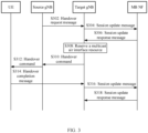
- Embodiment 1 includes the following steps: S302: The source gNB sends a handover request message, for example, a Handover Request message, to the target gNB, where the handover request message carries identification information of a PDU session, for example, a PDU session ID.
- a handover request message for example, a Handover Request message
- the handover request message may also carry a mode switching indication that may be used to indicate that a terminal needs to perform mode switching; and the handover request message may also indicate a target mode.
- the source gNB may use a specific QoS flow identifier to identify that the terminal needs to perform mode switching.
- S304 The target gNB sends a session update message to an MB NF according to the mode switching indication.
- the target gNB when the MB NF is a session management function (Session Management Function, SMF), the target gNB sends the session update message to the SMF through an access and mobility management function (Access and Mobility Management Function, AMF); or when the MB NF is an AMF, the target gNB directly sends the session update message to the AMF.
- the session update message may carry identification information of a to-be-switched PDU session, for example, a PDU session ID.
- S306 The MB NF sends a session update response message to the target gNB.
- the MB NF based on the PDU session ID, the MB NF matches information such as a TMGI, a corresponding QoS parameter, or a packet filtering rule of a multicast service that is being received by a user through the PDU session; and based on the QoS information corresponding to the PDU session and the packet filtering rule, adjusts the QoS information of the PDU session, for example, deletes a flow.
- information such as a TMGI, a corresponding QoS parameter, or a packet filtering rule of a multicast service that is being received by a user through the PDU session.
- the session update response message carries multicast QoS information obtained through adjustment, for example, a QoS parameter corresponding to the multicast service, and may also carry a QoS parameter (which may have been adjusted) corresponding to the PDU session; or the session update response message may also carry multicast information, for example, a TMGI and/or an identifier of the MB NF.
- the target gNB reserves a multicast air interface resource based on the multicast QoS information.
- the target gNB may further reserve an air interface resource for the PDU session based on the QoS parameter of the PDU session.
- the target gNB returns, to the source gNB, a handover command, for example, a Handover Response message, carrying an air interface resource.
- the air interface resource includes the multicast air interface resource, and may also include the air interface resource for the PDU session.
- S312 The source gNB forwards the air interface resource to the terminal UE by using a handover command.
- S314 The UE accesses the target gNB based on the multicast air interface resource, and sends, to the target gNB, a handover completion message, for example, a Handover Confirm message.
- the target gNB sends, to the MB NF, a session update message that may carry the received multicast information and may also carry multicast downlink tunnel resource information.
- S318 The MB NF returns a session update response message to the target gNB.
- the MB NF (for example, a UPF) may send multicast service data to the target gNB by using the multicast downlink tunnel resource, and the target gNB may send the multicast service data to the UE by using the multicast air interface resource.
- this embodiment includes the following steps:
- the MB NF Based on the PDU session ID, the MB NF matches information such as a TMGI, a corresponding QoS parameter, or a packet filtering rule of a multicast service that is being received by a user through the PDU session; and based on QoS information corresponding to the PDU session and the packet filtering rule, adjusts the QoS information of the PDU session, for example, deletes a flow.
- information such as a TMGI, a corresponding QoS parameter, or a packet filtering rule of a multicast service that is being received by a user through the PDU session.
- the handover request message may carry a mode switching indication that may indicate mode switching or may indicate a target mode, and specifically, a mode switching indication may also be indicated by using a multicast QoS parameter.
- the handover request message also carries QoS information obtained through adjustment, for example, multicast QoS information corresponding to the multicast service, and may also carry a QoS parameter (which may have been adjusted) corresponding to the PDU session.
- the handover request message may also carry multicast information, for example, a TMGI and/or an identifier of the MB NF.
- the target gNB reserves a multicast air interface resource, and may also reserve an air interface resource for the PDU session based on the QoS parameter of the PDU session.
- the target gNB may reserve the multicast air interface resource based on the mode switching indication and the multicast QoS information, or may reserve the multicast air interface resource only based on the multicast QoS information.
- the target gNB returns, to the MB NF, a handover response message, for example, a Handover Response message, carrying an air interface resource (which includes the multicast air interface resource, or may further includes the air interface resource for the PDU session if a flow is present in the PDU session) to be sent to the source gNB; and the target gNB may further reserve a multicast downlink tunnel resource for multicast service data that is used for sending the multicast service data to the target gNB by the MB NF.
- a handover response message for example, a Handover Response message, carrying an air interface resource (which includes the multicast air interface resource, or may further includes the air interface resource for the PDU session if a flow is present in the PDU session) to be sent to the source gNB; and the target gNB may further reserve a multicast downlink tunnel resource for multicast service data that is used for sending the multicast service data to the target gNB by the MB NF.
- the MB NF sends, to the source gNB, a handover command, for example, a Handover Command message, carrying an air interface resource.
- a handover command for example, a Handover Command message
- the air interface resource includes the multicast air interface resource, and may also include the air interface resource for the PDU session.
- S412 The source gNB forwards the air interface resource to a terminal UE.
- S414 The UE accesses the target gNB based on the multicast air interface resource, and sends, to the target gNB, a handover completion message, for example, a Handover Confirm message.
- the target gNB sends, to the MB NF, a session update message that may carry the received multicast information, where the multicast downlink tunnel resource information is sent in this step S416 if not yet being sent in step S408.
- S418 The MB NF returns a session update response message to the target gNB.
- the MB NF (for example, a UPF) may send multicast service data to the target gNB by using the multicast downlink tunnel resource, and the target gNB may send the multicast service data to the UE by using the multicast air interface resource.
- FIG. 5 is a schematic implementation flowchart of a mode switching method according to this embodiment of this application, and the method is applicable to the MB NF side.
- the method 500 includes the following steps: S502: Send multicast QoS information to a target network-side device, where the multicast QoS information is used for the target network-side device to reserve a multicast air interface resource.
- the multicast air interface resource is used for a terminal to receive multicast service data in a switched-to target mode, and the multicast QoS information corresponds to the multicast service data.
- the target network-side device reserves the multicast air interface resource, and sends the multicast air interface resource to a source network-side device or the MB NF, so that the terminal can switch from a PDU session mode to the target mode and receives the multicast service data by using the multicast air interface resource, thereby improving switching efficiency of mode switching.
- the method further includes: receiving the multicast air interface resource.
- the method further includes: receiving identification information of a PDU session from the target network-side device, where the identification information of the PDU session is sent by the source network-side device to the target network-side device.
- the method further includes: sending to the target network-side device at least one of the following: a QoS parameter corresponding to the PDU session; and multicast information.
- the method further includes: sending to the target network-side device at least one of the following:
- the method further includes: receiving, from the target network-side device, at least one of the following: an air interface resource for a PDU session, and a multicast downlink tunnel resource for sending the multicast service data.
- the method further includes: sending the multicast service data by using the multicast downlink tunnel resource.
- FIG. 6 is a schematic implementation flowchart of a mode switching method according to this embodiment of this application, and the method is applicable to the source network-side device side.
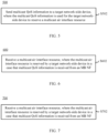
- the method 600 includes the following steps: S602: Receive a multicast air interface resource, where the multicast air interface resource is reserved by a target network-side device in a case that multicast QoS information is received from an MB NF.
- the multicast air interface resource is used for a terminal to receive multicast service data in a switched-to target mode, and the multicast QoS information corresponds to the multicast service data.
- a source network-side device receives the multicast air interface resource, where the multicast air interface resource is reserved by the target network-side device in the case that the multicast QoS information is received from the MB NF, and the source network-side device may further send the multicast air interface resource to the terminal, so that the terminal can switch from a PDU session mode to the target mode and receives the multicast service data by using the multicast air interface resource, thereby improving switching efficiency of mode switching.
- the method further includes: sending identification information of a PDU session to the target network-side device.
- FIG. 7 is a schematic implementation flowchart of a mode switching method according to this embodiment of this application, and the method is applicable to the terminal side. As shown in FIG. 7 , the method 700 includes the following steps: S702: Receive a multicast air interface resource, where the multicast air interface resource is reserved by a target network-side device in a case that multicast QoS information is received from an MB NF.
- the multicast air interface resource is used for the terminal to receive multicast service data in a switched-to target mode, and the multicast QoS information corresponds to the multicast service data.
- the terminal receives the multicast air interface resource, where the multicast air interface resource is reserved by the target network-side device in the case that the multicast QoS information is received from the MB NF, so that the terminal can switch from a PDU session mode to the target mode and receives the multicast service data by using the multicast air interface resource, thereby improving switching efficiency of mode switching.
- the execution body may be a mode switching apparatus, or a control module for executing the mode switching method in the mode switching apparatus.
- the mode switching apparatus provided in the embodiments of this application is described by using the mode switching method being executed by the mode switching apparatus as an example.
- FIG. 8 is a schematic structural diagram of a mode switching apparatus according to an embodiment of this application.
- the apparatus corresponds to the target network-side device described in the foregoing embodiments.
- the apparatus 800 includes:
- the target network-side device reserves the multicast air interface resource, and sends the multicast air interface resource to the source network-side device or the MB NF, so that the terminal can switch from a PDU session mode to the target mode and receives the multicast service data by using the multicast air interface resource, thereby improving switching efficiency of mode switching.
- the apparatus 800 further includes a receiving module, configured to receive identification information of a protocol data unit PDU session from the source network-side device; and the sending module 804 may be configured to send the identification information of the PDU session to the MB NF.
- the apparatus 800 further includes a receiving module, configured to receive, from the source network-side device, at least one of the following:
- the mode switching indication includes a specific QoS flow identifier.
- the apparatus 800 further includes a receiving module, configured to receive, from the MB NF, at least one of the following:
- the apparatus 800 further includes a receiving module, configured to receive, from the MB NF, at least one of the following:
- the resource reservation module 802 may be configured to reserve an air interface resource for the PDU session.
- the sending module 804 may be configured to send to the MB NF at least one of the following:
- the apparatus 800 further includes a receiving module, configured to receive the multicast service data by using the multicast downlink tunnel resource.
- the sending module 804 may be configured to send the multicast service data to the terminal by using the multicast air interface resource.
- FIG. 9 is a schematic structural diagram of a mode switching apparatus according to an embodiment of this application.
- the apparatus corresponds to the MB NF described in the foregoing embodiments.
- the apparatus 900 includes: a sending module 902, configured to send multicast QoS information to a target network-side device, where the multicast QoS information is used for the target network-side device to reserve a multicast air interface resource, the multicast air interface resource is used for a terminal to receive multicast service data in a switched-to target mode, and the multicast QoS information corresponds to the multicast service data.
- the target network-side device reserves the multicast air interface resource, and sends the multicast air interface resource to a source network-side device or the MB NF, so that the terminal can switch from a PDU session mode to the target mode and receives the multicast service data by using the multicast air interface resource, thereby improving switching efficiency of mode switching.
- the apparatus 900 further includes a receiving module, configured to receive the multicast air interface resource.
- the apparatus 900 further includes a receiving module, configured to receive identification information of a PDU session from the target network-side device, where the identification information of the PDU session is sent by the source network-side device to the target network-side device.
- a receiving module configured to receive identification information of a PDU session from the target network-side device, where the identification information of the PDU session is sent by the source network-side device to the target network-side device.
- the sending module 902 may be configured to send to the target network-side device at least one of the following: a QoS parameter corresponding to the PDU session; and multicast information.
- the sending module 902 may be configured to send to the target network-side device at least one of the following:
- the apparatus 900 further includes a receiving module, configured to receive, from the target network-side device, at least one of the following: an air interface resource for a PDU session, and a multicast downlink tunnel resource for sending the multicast service data.
- a receiving module configured to receive, from the target network-side device, at least one of the following: an air interface resource for a PDU session, and a multicast downlink tunnel resource for sending the multicast service data.
- the sending module 902 may be configured to send the multicast service data by using the multicast downlink tunnel resource.
- FIG. 10 is a schematic structural diagram of a mode switching apparatus according to an embodiment of this application.
- the apparatus corresponds to the source network-side device described in the foregoing embodiments.
- the apparatus 1000 includes: a receiving module 1002, configured to receive a multicast air interface resource, where the multicast air interface resource is reserved by a target network-side device in a case that multicast QoS information is received from an MB NF, the multicast air interface resource is used for a terminal to receive multicast service data in a switched-to target mode, and the multicast QoS information corresponds to the multicast service data.
- the mode switching apparatus receives the multicast air interface resource, where the multicast air interface resource is reserved by the target network-side device in the case that the multicast QoS information is received from the MB NF, and the mode switching apparatus may further send the multicast air interface resource to the terminal, so that the terminal can switch from a PDU session mode to the target mode and receives the multicast service data by using the multicast air interface resource, thereby improving switching efficiency of mode switching.
- the apparatus 1000 includes a sending module, configured to send identification information of a PDU session to the target network-side device.
- FIG. 11 is a schematic structural diagram of a mode switching apparatus according to an embodiment of this application.
- the apparatus corresponds to the terminal described in the foregoing embodiments.
- the apparatus 1100 includes: a receiving module 1102, configured to receive a multicast air interface resource, where the multicast air interface resource is reserved by a target network-side device in a case that multicast QoS information is received from an MB NF, the multicast air interface resource is used for the apparatus to receive multicast service data in a switched-to target mode, and the multicast QoS information corresponds to the multicast service data.
- the mode switching apparatus receives the multicast air interface resource, where the multicast air interface resource is reserved by the target network-side device in the case that the multicast QoS information is received from the MB NF, so that the mode switching apparatus, for example, the terminal, can switch from a PDU session mode to the target mode and receives the multicast service data by using the multicast air interface resource, thereby improving switching efficiency of mode switching.
- the mode switching apparatus in this embodiment of this application may be an apparatus, or may be a component, an integrated circuit, or a chip in a terminal.
- the apparatus may be a mobile terminal or a non-mobile terminal.
- the mobile terminal may include but is not limited to the types of the terminal 11 listed above, and the non-mobile terminal may be a server, a network attached storage (Network Attached Storage, NAS), a personal computer (personal computer, PC), a television (television, TV), a teller machine, a self-service machine, or the like, which is not specifically limited in this embodiment of this application.
- Network Attached Storage Network Attached Storage
- the mode switching apparatus in this embodiment of this application may be an apparatus with an operating system.
- the operating system may be an Android (Android) operating system, an iOS operating system, or other possible operating systems, and is not specifically limited in the embodiments of this application.
- the mode switching apparatus provided in this embodiment of this application is capable of implementing the processes implemented in the method embodiments in FIG. 2 to FIG. 7 , with the same technical effects achieved. To avoid repetition, details are not described herein again.
- an embodiment of this application further provides a communications device 1200, including a processor 1201, a memory 1202, and a program or instructions stored in the memory 1202 and capable of running on the processor 1201.
- a communications device 1200 including a processor 1201, a memory 1202, and a program or instructions stored in the memory 1202 and capable of running on the processor 1201.
- the communications device 1200 is a terminal and when the program or instructions are executed by the processor 1201, the processes of the foregoing embodiment of the mode switching method are implemented, with the same technical effects achieved.
- the communications device 1200 is a network-side device and when the program or instructions are executed by the processor 1201, the processes of the foregoing embodiment of the mode switching method are implemented, with the same technical effects achieved. To avoid repetition, details are not described herein again.
- FIG. 13 is a schematic diagram of a hardware structure of a terminal for implementing the embodiments of this application.
- the terminal 1300 includes but is not limited to components such as a radio frequency unit 1301, a network module 1302, an audio output unit 1303, an input unit 1304, a sensor 1305, a display unit 1306, a user input unit 1307, an interface unit 1308, a memory 1309, and a processor 1310.
- the terminal 1300 may further include a power supply (for example, a battery) supplying power to the components, and the power supply may be logically connected to the processor 1310 through a power management system. In this way, functions such as charge management, discharge management, and power consumption management are implemented by using the power management system.
- a power supply for example, a battery
- the structure of the terminal shown in FIG. 13 does not constitute any limitation on the terminal.
- the terminal may include more or fewer components than shown in FIG. 13 , or a combination of some components, or the components disposed differently. Details are not described herein again.
- the input unit 1304 may include a graphics processing unit (Graphics Processing Unit, GPU) 13041 and a microphone 13042.
- the graphics processing unit 13041 processes image data of a still picture or video obtained by an image capture apparatus (such as a camera) in a video capture mode or an image capture mode.
- the display unit 1306 may include a display panel 13061, and the display panel 13061 may be configured in a form of a liquid crystal display, an organic light-emitting diode, and the like.
- the user input unit 1307 may include a touch panel 13071 and other input devices 13072.
- the touch panel 13071 is also referred to as a touchscreen.
- the touch panel 13071 may include two parts: a touch detection apparatus and a touch controller.
- the other input devices 13072 may include but are not limited to a physical keyboard, a function key (such as a volume control key or a power on/off key), a trackball, a mouse, a joystick, and the like. Details are not described herein.
- the radio frequency unit 1301 receives downlink data from a network-side device, and then sends the downlink data to the processor 1310 for processing; and also sends uplink data to the network-side device.
- the radio frequency unit 1301 includes but is not limited to an antenna, at least one amplifier, a transceiver, a coupler, a low noise amplifier, a duplexer, and the like.
- the memory 1309 may be configured to store software programs or instructions and various data.
- the memory 1309 may mainly include a program or instruction storage area and a data storage area.
- the program or instruction storage area may store an operating system, an application program or instruction required by at least one function (for example, a sound playback function or an image playback function), and the like.
- the memory 1309 may include a high-speed random access memory, and may further include a non-volatile memory.
- the non-volatile memory may be a read-only memory (Read-Only Memory, ROM), a programmable read-only memory (programmable ROM, PROM), an erasable programmable read-only memory (erasable PROM, EPROM), an electrically erasable programmable read-only memory (electrically EPROM, EEPROM), or a flash memory, for example, at least one disk storage device, a flash memory device, or another volatile solid-state storage device.
- ROM Read-Only Memory
- PROM programmable read-only memory
- EPROM erasable programmable read-only memory
- EPROM erasable programmable read-only memory
- electrically erasable programmable read-only memory electrically erasable programmable read-only memory
- EEPROM electrically erasable programmable read-only memory
- flash memory for example, at least one disk storage device, a flash memory device, or another volatile solid-state storage device.
- the processor 1310 may include one or more processing units.
- an application processor and a modem processor may be integrated in the processor 1310.
- the application processor primarily processes an operating system, user interfaces, application programs or instructions, and the like.
- the modem processor primarily processes radio communication, for example, being a baseband processor. It can be understood that the modem processor may alternatively be not integrated in the processor 1310.
- the radio frequency unit 1301 is configured to receive a multicast air interface resource, where the multicast air interface resource is reserved by a target network-side device in a case that multicast QoS information is received from an MB NF.
- the multicast air interface resource is used for the terminal to receive multicast service data in a switched-to target mode, and the multicast QoS information corresponds to the multicast service data.
- the terminal receives the multicast air interface resource, where the multicast air interface resource is reserved by the target network-side device in the case that the multicast QoS information is received from the MB NF, so that the terminal can switch from a PDU session mode to the target mode and receives the multicast service data by using the multicast air interface resource, thereby improving switching efficiency of mode switching.
- the network-side device 1400 includes an antenna 141, a radio frequency apparatus 142, and a baseband apparatus 143.
- the antenna 141 is connected to the radio frequency apparatus 142.
- the radio frequency apparatus 142 receives information by using the antenna 141, and sends the received information to the baseband apparatus 143 for processing.
- the baseband apparatus 143 processes to-be-sent information, and sends the information to the radio frequency apparatus 142; and the radio frequency apparatus 142 processes the received information and then sends the information out by using the antenna 141.
- the radio frequency apparatus 142 may be located in the baseband apparatus 143.
- the method performed by the network-side device in the foregoing embodiments may be implemented in the baseband apparatus 143, and the baseband apparatus 143 includes a processor 144 and a memory 145.
- the baseband apparatus 143 may include, for example, at least one baseband processing unit, where a plurality of chips are disposed on the baseband processing unit. As shown in FIG. 14 , one of the chips is, for example, the processor 144, and is connected to the memory 145, to invoke a program in the memory 145 to perform the operation of the network-side device shown in the foregoing method embodiment.
- the baseband apparatus 143 may further include a network interface 146, configured to exchange information with the radio frequency apparatus 142, where the interface is, for example, a common public radio interface (common public radio interface, CPRI for short).
- a network interface 146 configured to exchange information with the radio frequency apparatus 142, where the interface is, for example, a common public radio interface (common public radio interface, CPRI for short).
- the network-side device in this embodiment of the present invention further includes: an instruction or a program stored in the memory 145 and capable of running on the processor 144.
- the processor 144 invokes the instruction or program in the memory 145 to execute the method executed by the modules shown in FIG. 2 to FIG. 6 , with the same technical effects achieved. To avoid repetition, details are not repeated herein.
- An embodiment of this application further provides a readable storage medium, where the readable storage medium stores a program or instructions.
- the program or instructions are executed by a processor, the processes of the foregoing embodiments of the mode switching method can be implemented, with the same technical effects achieved. To avoid repetition, details are not described herein again.
- the processor is a processor in the terminal described in the foregoing embodiments.
- the readable storage medium includes a computer-readable storage medium, for example, a computer read-only memory (Read-Only Memory, ROM), a random access memory (Random Access Memory, RAM), a magnetic disk, or an optical disc.
- An embodiment of this application further provides a chip, where the chip includes a processor and a communications interface.
- the communications interface is coupled to the processor, and the processor is configured to run a program or instructions to implement the processes of the foregoing embodiments of the mode switching method, with the same technical effects achieved. To avoid repetition, details are not described herein again.
- the chip mentioned in the embodiments of this application may also be referred to as a system-level chip, a system chip, a chip system, a system-on-chip, or the like.
- the methods in the foregoing embodiments may be implemented by using software in combination with a necessary common hardware platform, and certainly may alternatively be implemented by using hardware. However, in most cases, the former is a preferred implementation.
- the technical solutions of the present invention essentially or the part contributing to the prior art may be implemented in a form of a software product.
- the software product is stored in a storage medium (such as a ROM/RAM, a magnetic disk, or an optical disc), and includes several instructions for instructing a terminal (which may be a mobile phone, a computer, a server, an air conditioner, a network device, or the like) to perform the methods described in the embodiments of this disclosure.
Landscapes
- Engineering & Computer Science (AREA)
- Computer Networks & Wireless Communication (AREA)
- Signal Processing (AREA)
- Quality & Reliability (AREA)
- Multimedia (AREA)
- Mobile Radio Communication Systems (AREA)
- Data Exchanges In Wide-Area Networks (AREA)
Abstract
Description
- This application claims priority to
Chinese Patent Application No. 202010519756.2, filed in China on June 9, 2020 - This application pertains to the field of communications technologies, and specifically relates to a mode switching method, a terminal, and a network-side device.
- A terminal may establish a protocol data unit (Protocol Data Unit, PDU) session (Session) to a data network (Data Network, DN) network element through a user plane function (User Plane Function, UPF) network element, and the PDU session provides PDU connectivity service between the terminal and the DN network element.
- For a terminal using a point-to-point PDU session mode to receive multicast traffic to switch to a target network-side device supporting point-to-multipoint multicast, the terminal has to use a PDU session switching procedure to first switch the PDU session to the target network-side device. If the terminal wants to use the more efficient multicast data transmission mode, a mode switching has to be initiated by the terminal or the target network-side device so as to switch to the point-to-multipoint multicast transmission mode.
- It can be learned from the foregoing description that the terminal needs to first switch the PDU session to the target network-side device by using the PDU session switching procedure, and then the terminal or the target network-side device initiates mode switching so as to switch to the point-to-multipoint multicast transmission mode. Such mode switching features relatively low switching efficiency.
- The purpose of embodiments of this application is to provide a mode switching method, a terminal, and a network-side device, so as to resolve a problem of low switching efficiency of mode switching.
- In order to resolve the foregoing technical problem, this application is implemented as follows:
According to a first aspect, a mode switching method is provided, applied to a target network-side device, and the method includes: reserving a multicast air interface resource in a case that multicast quality of service QoS information is received from a multicast broadcast network function MB NF, where the multicast air interface resource is used for a terminal to receive multicast service data in a switched-to target mode, and the multicast QoS information corresponds to the multicast service data; and sending the multicast air interface resource to a source network-side device or the MB NF. - According to a second aspect, a mode switching method is provided, applied to an MB NF, and the method includes: sending multicast QoS information to a target network-side device, where the multicast QoS information is used for the target network-side device to reserve a multicast air interface resource, the multicast air interface resource is used for a terminal to receive multicast service data in a switched-to target mode, and the multicast QoS information corresponds to the multicast service data.
- According to a third aspect, a mode switching method is provided, applied to a source network-side device, and the method includes: receiving a multicast air interface resource, where the multicast air interface resource is reserved by a target network-side device in a case that multicast QoS information is received from an MB NF, the multicast air interface resource is used for a terminal to receive multicast service data in a switched-to target mode, and the multicast QoS information corresponds to the multicast service data.
- According to a fourth aspect, a mode switching method is provided, applied to a terminal, and the method includes: receiving a multicast air interface resource, where the multicast air interface resource is reserved by a target network-side device in a case that multicast QoS information is received from an MB NF, the multicast air interface resource is used for the terminal to receive multicast service data in a switched-to target mode, and the multicast QoS information corresponds to the multicast service data.
- According to a fifth aspect, a mode switching apparatus is provided, and the apparatus includes: a resource reservation module, configured to reserve a multicast air interface resource in a case that multicast quality of service QoS information is received from a multicast broadcast network function MB NF, where the multicast air interface resource is used for a terminal to receive multicast service data in a switched-to target mode, and the multicast QoS information corresponds to the multicast service data; and a sending module, configured to send the multicast air interface resource to a source network-side device or the MB NF.
- According to a sixth aspect, a mode switching apparatus is provided, and the apparatus includes: a sending module, configured to send multicast QoS information to a target network-side device, where the multicast QoS information is used for the target network-side device to reserve a multicast air interface resource, the multicast air interface resource is used for a terminal to receive multicast service data in a switched-to target mode, and the multicast QoS information corresponds to the multicast service data.
- According to a seventh aspect, a mode switching apparatus is provided, and the apparatus includes: a receiving module, configured to receive a multicast air interface resource, where the multicast air interface resource is reserved by a target network-side device in a case that multicast QoS information is received from an MB NF, the multicast air interface resource is used for a terminal to receive multicast service data in a switched-to target mode, and the multicast QoS information corresponds to the multicast service data.
- According to an eighth aspect, a mode switching apparatus is provided, and the apparatus includes: a receiving module, configured to receive a multicast air interface resource, where the multicast air interface resource is reserved by a target network-side device in a case that multicast QoS information is received from an MB NF, the multicast air interface resource is used for the apparatus to receive multicast service data in a switched-to target mode, and the multicast QoS information corresponds to the multicast service data.
- According to a ninth aspect, a terminal is provided, where the terminal includes a processor, a memory, and a program or instructions stored in the memory and capable of running on the processor, and when the program or instructions are executed by the processor, the method according to the fourth aspect is implemented.
- According to a tenth aspect, a network-side device is provided, where the network-side device includes a processor, a memory, and a program or instructions stored in the memory and capable of running on the processor, and when the program or instructions are executed by the processor, the method according to the first aspect, the second aspect, or the third aspect is implemented.
- According to an eleventh aspect, a readable storage medium is provided, where the readable storage medium stores a program or instructions. When the program or instructions are executed by a processor, the method according to the first aspect, the second aspect, the third aspect, or the fourth aspect is implemented.
- According to a twelfth aspect, a chip is provided, where the chip includes a processor and a communications interface, the communications interface is coupled to the processor, and the processor is configured to run a program or instructions to implement the method according to the first aspect, the second aspect, the third aspect, or the fourth aspect.
- In the embodiments of this application, in the case of receiving the multicast QoS information from the MB NF, the target network-side device reserves the multicast air interface resource, and sends the multicast air interface resource to the source network-side device or the MB NF, so that the terminal can switch from a PDU session mode to the target mode and receives the multicast service data by using the multicast air interface resource, thereby improving switching efficiency of mode switching.
-
-
FIG. 1 is a block diagram of a wireless communications system according to an embodiment of this application; -
FIG. 2 is a schematic flowchart of a mode switching method according to an embodiment of this application; -
FIG. 3 is a schematic flowchart of a mode switching method according to an embodiment of this application; -
FIG. 4 is a schematic flowchart of a mode switching method according to an embodiment of this application; -
FIG. 5 is a schematic flowchart of a mode switching method according to an embodiment of this application; -
FIG. 6 is a schematic flowchart of a mode switching method according to an embodiment of this application; -
FIG. 7 is a schematic flowchart of a mode switching method according to an embodiment of this application; -
FIG. 8 is a schematic structural diagram of a mode switching apparatus according to an embodiment of this application; -
FIG. 9 is a schematic structural diagram of a mode switching apparatus according to an embodiment of this application; -
FIG. 10 is a schematic structural diagram of a mode switching apparatus according to an embodiment of this application; -
FIG. 11 is a schematic structural diagram of a mode switching apparatus according to an embodiment of this application; -
FIG. 12 is a schematic structural diagram of a communications device according to an embodiment of this application; -
FIG. 13 is a schematic structural diagram of a terminal according to an embodiment of this application; and -
FIG. 14 is a schematic structural diagram of a network-side device according to an embodiment of this application. - The following clearly and completely describes the technical solutions in the embodiments of this application with reference to the accompanying drawings in the embodiments of this application. Apparently, the described embodiments are only some rather than all of the embodiments of this application. All other embodiments obtained by a person of ordinary skill in the art based on the embodiments of this application without creative efforts shall fall within the protection scope of this application.
- In the specification and claims of this application, the terms such as "first" and "second" are intended to distinguish between similar objects but do not necessarily indicate a specific order or sequence. It should be understood that the data used in this way is interchangeable in appropriate circumstances so that the embodiments of this application can be implemented in other orders than the order illustrated or described herein, and "first" and "second" are usually for distinguishing same-type objects but not limiting the number of objects, for example, a first object may be one or multiple. In addition, "and/or" in this specification and claims indicates at least one of connected objects, and the symbol "/" generally indicates that the associated objects are in an "or" relationship.
- It should be noted that techniques described in the embodiments of this application are not limited to a long term evolution (Long Term Evolution, LTE) or LTE-Advanced (LTE-Advanced, LTE-A) system, and may also be applied to various wireless communications systems, for example, code division multiple access (Code Division Multiple Access, CDMA), time division multiple access (Time Division Multiple Access, TDMA), frequency division multiple access (Frequency Division Multiple Access, FDMA), orthogonal frequency division multiple access (Orthogonal Frequency Division Multiple Access, OFDMA), single-carrier frequency-division multiple access (Single-carrier Frequency-Division Multiple Access, SC-FDMA), and other systems. The terms "system" and "network" in the embodiments of this application are usually used interchangeably. Techniques described herein may be used in the aforementioned systems and radio technologies, and may also be used in other systems and radio technologies. However, in the following descriptions, a new radio (New Radio, NR) system is described for an illustration purpose, and NR terms are used in most of the following descriptions, although these technologies may also be applied to other applications than the NR system application, for example, the sixth generation (6th Generation, 6G) communications system.
-
FIG. 1 is a block diagram of a wireless communications system to which the embodiments of this application are applicable. The wireless communications system includes aterminal 11 and a network-side device 12. Theterminal 11 may also be referred to as a terminal device or a user terminal (User Equipment, UE), and theterminal 11 may be a terminal-side device, such as a mobile phone, a tablet computer (Tablet Personal Computer), a laptop computer (Laptop Computer) or a notebook computer, a personal digital assistant (Personal Digital Assistant, PDA), a palmtop computer, a netbook, an ultra-mobile personal computer (ultra-mobile personal computer, UMPC), a mobile Internet device (Mobile Internet Device, MID), a wearable device (Wearable Device) or an in-vehicle device (VUE), or a pedestrian terminal (PUE). The wearable device includes: a wrist band, earphones, glasses, or the like. It should be noted that a specific type of theterminal 11 is not limited in the embodiments of this application. The network-side device 12 may be a base station or a core network. The base station may be referred to as a NodeB, an evolved NodeB, an access point, a base transceiver station (Base Transceiver Station, BTS), a radio base station, a radio transceiver, a basic service set (Basic Service Set, BSS), an extended service set (Extended Service Set, ESS), a home NodeB, a home evolved NodeB, a WLAN access point, a Wi-Fi node, a transmission reception point (Transmitting Receiving Point, TRP), or another appropriate term in the art. Provided that a same technical effect is achieved, the base station is not limited to a specific technical term. It should be noted that in the embodiments of this application, the base station in the NR system is merely used as an example, and a specific type of the base station is not limited. - The following describes in detail a mode switching method, a terminal, and a network-side device provided in the embodiments of this application by using specific embodiments and application scenarios thereof with reference to the accompanying drawings.
- As shown in
FIG. 2 , an embodiment of this application provides amode switching method 200, and the method may be executed by a target network-side device. In other words, the method may be executed by software or hardware installed in the target network-side device, and themethod 200 includes the following steps. - S202: Reserve a multicast air interface resource in a case that multicast quality of service (Quality of Service, QoS) information is received from a multicast broadcast network function (Multicast Broadcast Network Function, MB NF).
- The multicast air interface resource is used for a terminal to receive multicast service data in a switched-to target mode. The multicast QoS information corresponds to the multicast service data. In other words, the multicast QoS information is QoS information of the multicast service data.
- Before S202, the MB NF may send the multicast QoS information to the target network-side device. Generally, the multicast QoS information differs from "QoS information of a PDU session". In an example, the multicast QoS information sent by the MB NF to the target network-side device may also carry indication information, and the indication information is used to indicate that the multicast QoS information is applied to a multicast service.
- It should be noted that the MB NF mentioned in the embodiments of this specification is generally a core network function capable of providing multicast service data; therefore, the MB NF may be replaced with other technical terms, for example, a core network device or a multicast broadcast server.
- In this embodiment, in a cell provided by a source network-side device, the terminal may receive a multicast service in a point-to-point PDU session mode. The PDU session mode is based on individual channels, and generally each terminal corresponds to one channel, resulting in relatively low transmission efficiency of the multicast service data. After switching to a cell provided by the target network-side device, the terminal may switch to the target mode, where the target mode may be a point-to-multipoint multicast service transmission mode. For example, when the target network-side device sends one piece of multicast service data, a plurality of terminals are able to receive the multicast service data, which may improve transmission efficiency of the multicast service data in comparison with the PDU session mode. On a basis of the foregoing description, mode switching mentioned in the embodiments of this application may mean that the terminal switches from the PDU session mode of the source network-side device to the target mode of the target network-side device, and the target mode is the point-to-multipoint multicast service transmission mode.
- In this embodiment, in an example, before S202, the source network-side device of the terminal may send a handover request message to the target network-side device, and the switch request message may carry identification information of a protocol data unit (Protocol Data Unit, PDU) session, for example, a PDU session (Session) ID. In this way, after receiving the handover request message, the target network-side device may further send a session update message to the MB NF, and the session update message carries the identification information of the PDU session, for example, the PDU session ID, so that the MB NF may send the multicast QoS information to the target network-side device.
- In this embodiment, in another example, before S202, the source network-side device of the terminal may send a handover notification message to the MB NF, and the handover notification message may carries the identification information of the PDU session, for example, the PDU session ID. In this way, the MB NF may send the multicast QoS information to the target network-side device after receiving the handover notification message.
- S204: Send the multicast air interface resource to the source network-side device or the MB NF.
- In this embodiment, in a case that the target network-side device sends the multicast air interface resource to the source network-side device, the source network-side device may further forward the multicast air interface resource to the terminal; or in a case that the target network-side device sends the multicast air interface resource to the MB NF, the MB NF may further forward the multicast air interface resource to the terminal through the source network-side device. In this way, the terminal may hand over to the target network-side device by using the multicast air interface resource, and receives the multicast service data in a switched-to target mode.
- In an example, the target network-side device may send a handover command to the source network-side device, where the handover command carries the multicast air interface resource; and the source network-side device may further send, to the terminal, a handover command that carries the multicast air interface resource. In this way, the terminal may further access the target network-side device based on the multicast air interface resource, and sends to the target network-side device a handover completion message, for example, a Handover Confirm message.
- In another example, the target network-side device may send the multicast air interface resource to the MB NF, and the MB NF sends a handover command (for example, a Handover Command message) to the source network-side device, where the handover command carries the multicast air interface resource. The source network-side device may further send, to the terminal, a handover command that carries the multicast air interface resource. In this way, the terminal may further access the target network-side device based on the multicast air interface resource, and sends to the target network-side device a handover completion message, for example, a Handover Confirm message.
- According to the mode switching method provided in this embodiment of this application, in the case of receiving the multicast QoS information from the MB NF, the target network-side device reserves the multicast air interface resource, and sends the multicast air interface resource to the source network-side device or the MB NF, so that the terminal can switch from a PDU session mode to the target mode and receives the multicast service data by using the multicast air interface resource, thereby improving switching efficiency of mode switching.
- With respect to the improved efficiency of mode switching, in a related art, the terminal needs to first perform PDU session switching, and then switches from the PDU session to the target mode, and an air interface resource required for PDU session switching differs from an air interface resource required for the target mode. In this way, the target network-side device needs to not only reserve the air interface resource required for the PDU session but also reserve the air interface resource required for the target mode, and also needs to exchange signaling with the source network-side device, the terminal, and the like to notify the air interface resources, resulting in relatively low switching efficiency. In this embodiment of this application, there is no need to reserve the air interface resource required for PDU session switching, and a signaling exchange procedure required for notifying the air interface resources is omitted, thereby improving switching efficiency of mode switching.
- Optionally, before S202 of the
embodiment 200, the method further includes: receiving the identification information of the PDU session from the source network-side device; and sending the identification information of the PDU session to the MB NF. The PDU session mentioned in this example may also be referred to as a to-be-switched PDU session because the terminal is about to switch from the PDU session mode to the target mode. After receiving the identification information of the PDU session, the MB NF may learn that the terminal needs to perform mode switching, that is, the multicast QoS information can be sent to the target network-side device. - In this embodiment, after sending the identification information of the PDU session to the MB NF, the target network-side device may further receive, from the MB NF, at least one of the following: a QoS parameter corresponding to the PDU session, and multicast information. The multicast information, for example, includes at least one of a temporary mobile group identity (Temporary Mobile Group Identify, TMGI) and an identifier of the MB NF.
- Optionally, before S202 of the
embodiment 200, the method further includes: receiving, from the source network-side device, at least one of the following: a mode switching indication and the target mode. In an example, the mode switching indication includes a specific QoS flow identifier. In this embodiment, the source network-side device may send at least one of the mode switching indication and the target mode to the target network-side device, so as to indicate that the terminal needs to perform mode switching. In this way, the target network-side device may send a session update message to the MB NF, and after receiving the session update message, the MB NF may learn that the terminal needs to perform mode switching, that is, the multicast QoS information can be sent to the target network-side device. - Optionally, before S202 of the
embodiment 200, the method further includes: receiving, from the MB NF, at least one of the following: a mode switching indication, the target mode, a QoS parameter corresponding to the PDU session, and multicast information. - In the foregoing plurality of examples, in a case that the target network-side device receives the QoS parameter corresponding to the PDU session, the target network-side device may further reserve an air interface resource for the PDU session. In this way, the terminal can not only receive the multicast service data in the target mode, and also receive the multicast service data in the PDU session mode. This embodiment is applicable to a scenario where the terminal needs to receive a plurality of different types of multicast service data, so as to meet transmission requirements of a plurality of different multicast service data and also help improve transmission efficiency.
- Optionally, the
embodiment 200 further includes the following step: sending to the MB NF at least one of the following: an air interface resource for a PDU session, and a multicast downlink tunnel resource for receiving the multicast service data. - In this embodiment, in a case that the air interface resource for the PDU session is sent to the MB NF, the MB NF may further send the air interface resource for the PDU session to the terminal through the source network-side device, so that the terminal subsequently receives the multicast service data from the target network-side device in the PDU session mode.
- In this embodiment, in a case that the multicast downlink tunnel resource is sent to the MB NF, the target network-side device may further receive the multicast service data by using the multicast downlink tunnel resource and sends the multicast service data to the terminal by using the multicast air interface resource, so that the terminal may receive the multicast service data in the target mode by using the multicast air interface resource.
- The following describes in detail the mode switching method provided by the embodiments of this application with reference to two specific embodiments in
FIG. 3 andFIG. 4 . In the embodiments shown inFIG. 3 andFIG. 4 , the source network-side device being a source gNB and the target network-side device being a target gNB are used as examples for description. - As shown in
FIG. 3 , Embodiment 1 includes the following steps:
S302: The source gNB sends a handover request message, for example, a Handover Request message, to the target gNB, where the handover request message carries identification information of a PDU session, for example, a PDU session ID. - Optionally, the handover request message may also carry a mode switching indication that may be used to indicate that a terminal needs to perform mode switching; and the handover request message may also indicate a target mode. Optionally, the source gNB may use a specific QoS flow identifier to identify that the terminal needs to perform mode switching.
- S304: The target gNB sends a session update message to an MB NF according to the mode switching indication.
- For example, when the MB NF is a session management function (Session Management Function, SMF), the target gNB sends the session update message to the SMF through an access and mobility management function (Access and Mobility Management Function, AMF); or when the MB NF is an AMF, the target gNB directly sends the session update message to the AMF. The session update message may carry identification information of a to-be-switched PDU session, for example, a PDU session ID.
- S306: The MB NF sends a session update response message to the target gNB.
- In this embodiment, based on the PDU session ID, the MB NF matches information such as a TMGI, a corresponding QoS parameter, or a packet filtering rule of a multicast service that is being received by a user through the PDU session; and based on the QoS information corresponding to the PDU session and the packet filtering rule, adjusts the QoS information of the PDU session, for example, deletes a flow. The session update response message carries multicast QoS information obtained through adjustment, for example, a QoS parameter corresponding to the multicast service, and may also carry a QoS parameter (which may have been adjusted) corresponding to the PDU session; or the session update response message may also carry multicast information, for example, a TMGI and/or an identifier of the MB NF.
- S308: The target gNB reserves a multicast air interface resource based on the multicast QoS information.
- Optionally, the target gNB may further reserve an air interface resource for the PDU session based on the QoS parameter of the PDU session.
- S310: The target gNB returns, to the source gNB, a handover command, for example, a Handover Response message, carrying an air interface resource. The air interface resource includes the multicast air interface resource, and may also include the air interface resource for the PDU session.
- S312: The source gNB forwards the air interface resource to the terminal UE by using a handover command.
- S314: The UE accesses the target gNB based on the multicast air interface resource, and sends, to the target gNB, a handover completion message, for example, a Handover Confirm message.
- S316: The target gNB sends, to the MB NF, a session update message that may carry the received multicast information and may also carry multicast downlink tunnel resource information.
- S318: The MB NF returns a session update response message to the target gNB.
- In this case, the MB NF (for example, a UPF) may send multicast service data to the target gNB by using the multicast downlink tunnel resource, and the target gNB may send the multicast service data to the UE by using the multicast air interface resource.
- As shown in
FIG. 4 , this embodiment includes the following steps: - S402: A source gNB sends a handover notification message to an MB NF. For example, when the MB NF is an SMF, the source gNB sends the handover notification message to the SMF through an AMF; or when the MB NF is an AMF, the source gNB directly sends the handover notification message to the AMF, where the handover notification message (for example, a Handover Required message) may carry identification information of a to-be-switched PDU session, for example, a PDU session ID.
- S404: The MB NF sends, to a target gNB, a handover request message, for example, a Handover Request message.
- Based on the PDU session ID, the MB NF matches information such as a TMGI, a corresponding QoS parameter, or a packet filtering rule of a multicast service that is being received by a user through the PDU session; and based on QoS information corresponding to the PDU session and the packet filtering rule, adjusts the QoS information of the PDU session, for example, deletes a flow.
- The handover request message may carry a mode switching indication that may indicate mode switching or may indicate a target mode, and specifically, a mode switching indication may also be indicated by using a multicast QoS parameter. The handover request message also carries QoS information obtained through adjustment, for example, multicast QoS information corresponding to the multicast service, and may also carry a QoS parameter (which may have been adjusted) corresponding to the PDU session. The handover request message may also carry multicast information, for example, a TMGI and/or an identifier of the MB NF.
- S406: The target gNB reserves a multicast air interface resource, and may also reserve an air interface resource for the PDU session based on the QoS parameter of the PDU session.
- In this step, the target gNB may reserve the multicast air interface resource based on the mode switching indication and the multicast QoS information, or may reserve the multicast air interface resource only based on the multicast QoS information.
- S408: The target gNB returns, to the MB NF, a handover response message, for example, a Handover Response message, carrying an air interface resource (which includes the multicast air interface resource, or may further includes the air interface resource for the PDU session if a flow is present in the PDU session) to be sent to the source gNB; and the target gNB may further reserve a multicast downlink tunnel resource for multicast service data that is used for sending the multicast service data to the target gNB by the MB NF.
- S410: The MB NF sends, to the source gNB, a handover command, for example, a Handover Command message, carrying an air interface resource. The air interface resource includes the multicast air interface resource, and may also include the air interface resource for the PDU session.
- S412: The source gNB forwards the air interface resource to a terminal UE.
- S414: The UE accesses the target gNB based on the multicast air interface resource, and sends, to the target gNB, a handover completion message, for example, a Handover Confirm message.
- S416: The target gNB sends, to the MB NF, a session update message that may carry the received multicast information, where the multicast downlink tunnel resource information is sent in this step S416 if not yet being sent in step S408.
- S418: The MB NF returns a session update response message to the target gNB.
- In this case, the MB NF (for example, a UPF) may send multicast service data to the target gNB by using the multicast downlink tunnel resource, and the target gNB may send the multicast service data to the UE by using the multicast air interface resource.
- The foregoing describes in detail the mode switching method in this embodiment of this application with reference to
FIG. 2 to FIG. 4 . The following describes in detail the mode switching method in several other embodiments of this application with reference toFIG. 5 to FIG. 7 . It can be understood that descriptions on the MB NF side, the source network-side device side, and the terminal side are the same as the description of the method shown inFIG. 2 to FIG. 4 on the target network-side device side. To avoid repetition, related descriptions are appropriately omitted. -
FIG. 5 is a schematic implementation flowchart of a mode switching method according to this embodiment of this application, and the method is applicable to the MB NF side. As shown inFIG. 5 , themethod 500 includes the following steps:
S502: Send multicast QoS information to a target network-side device, where the multicast QoS information is used for the target network-side device to reserve a multicast air interface resource. - The multicast air interface resource is used for a terminal to receive multicast service data in a switched-to target mode, and the multicast QoS information corresponds to the multicast service data.
- In this embodiment of this application, in the case of receiving the multicast QoS information from the MB NF, the target network-side device reserves the multicast air interface resource, and sends the multicast air interface resource to a source network-side device or the MB NF, so that the terminal can switch from a PDU session mode to the target mode and receives the multicast service data by using the multicast air interface resource, thereby improving switching efficiency of mode switching.
- Optionally, in an embodiment, the method further includes: receiving the multicast air interface resource.
- Optionally, in an embodiment, the method further includes: receiving identification information of a PDU session from the target network-side device, where the identification information of the PDU session is sent by the source network-side device to the target network-side device.
- Optionally, in an embodiment, the method further includes: sending to the target network-side device at least one of the following: a QoS parameter corresponding to the PDU session; and multicast information.
- Optionally, in an embodiment, the method further includes: sending to the target network-side device at least one of the following:
- a mode switching indication;
- the target mode;
- a QoS parameter corresponding to the PDU session; and
- multicast information.
- Optionally, in an embodiment, the method further includes: receiving, from the target network-side device, at least one of the following: an air interface resource for a PDU session, and a multicast downlink tunnel resource for sending the multicast service data.
- Optionally, in an embodiment, the method further includes: sending the multicast service data by using the multicast downlink tunnel resource.
-
FIG. 6 is a schematic implementation flowchart of a mode switching method according to this embodiment of this application, and the method is applicable to the source network-side device side. As shown inFIG. 6 , themethod 600 includes the following steps:
S602: Receive a multicast air interface resource, where the multicast air interface resource is reserved by a target network-side device in a case that multicast QoS information is received from an MB NF. - The multicast air interface resource is used for a terminal to receive multicast service data in a switched-to target mode, and the multicast QoS information corresponds to the multicast service data.
- In this embodiment of this application, a source network-side device receives the multicast air interface resource, where the multicast air interface resource is reserved by the target network-side device in the case that the multicast QoS information is received from the MB NF, and the source network-side device may further send the multicast air interface resource to the terminal, so that the terminal can switch from a PDU session mode to the target mode and receives the multicast service data by using the multicast air interface resource, thereby improving switching efficiency of mode switching.
- Optionally, in an embodiment, the method further includes: sending identification information of a PDU session to the target network-side device.
FIG. 7 is a schematic implementation flowchart of a mode switching method according to this embodiment of this application, and the method is applicable to the terminal side. As shown inFIG. 7 , themethod 700 includes the following steps:
S702: Receive a multicast air interface resource, where the multicast air interface resource is reserved by a target network-side device in a case that multicast QoS information is received from an MB NF. - The multicast air interface resource is used for the terminal to receive multicast service data in a switched-to target mode, and the multicast QoS information corresponds to the multicast service data.
- In this embodiment of this application, the terminal receives the multicast air interface resource, where the multicast air interface resource is reserved by the target network-side device in the case that the multicast QoS information is received from the MB NF, so that the terminal can switch from a PDU session mode to the target mode and receives the multicast service data by using the multicast air interface resource, thereby improving switching efficiency of mode switching.
- It should be noted that, for the mode switching method provided by the embodiments of this application, the execution body may be a mode switching apparatus, or a control module for executing the mode switching method in the mode switching apparatus. In the embodiments of this application, the mode switching apparatus provided in the embodiments of this application is described by using the mode switching method being executed by the mode switching apparatus as an example.
-
FIG. 8 is a schematic structural diagram of a mode switching apparatus according to an embodiment of this application. The apparatus corresponds to the target network-side device described in the foregoing embodiments. As shown inFIG. 8 , the apparatus 800 includes: - a
resource reservation module 802, configured to reserve a multicast air interface resource in a case that multicast QoS information is received from an MB NF, where the multicast air interface resource is used for a terminal to receive multicast service data in a switched-to target mode, and the multicast QoS information corresponds to the multicast service data; and - a sending
module 804, configured to send the multicast air interface resource to a source network-side device or the MB NF. - In this embodiment of this application, in the case of receiving the multicast QoS information from the MB NF, the target network-side device reserves the multicast air interface resource, and sends the multicast air interface resource to the source network-side device or the MB NF, so that the terminal can switch from a PDU session mode to the target mode and receives the multicast service data by using the multicast air interface resource, thereby improving switching efficiency of mode switching.
- Optionally, in an embodiment, the apparatus 800 further includes a receiving module, configured to receive identification information of a protocol data unit PDU session from the source network-side device; and the sending
module 804 may be configured to send the identification information of the PDU session to the MB NF. - Optionally, in an embodiment, the apparatus 800 further includes a receiving module, configured to receive, from the source network-side device, at least one of the following:
- a mode switching indication; and
- the target mode.
- Optionally, in an embodiment, the mode switching indication includes a specific QoS flow identifier.
- Optionally, in an embodiment, the apparatus 800 further includes a receiving module, configured to receive, from the MB NF, at least one of the following:
- a QoS parameter corresponding to the PDU session; and
- multicast information.
- Optionally, in an embodiment, the apparatus 800 further includes a receiving module, configured to receive, from the MB NF, at least one of the following:
- a mode switching indication;
- the target mode;
- a QoS parameter corresponding to the PDU session; and
- multicast information.
- Optionally, in an embodiment, in a case that the QoS parameter corresponding to the PDU session is received, the
resource reservation module 802 may be configured to reserve an air interface resource for the PDU session. - Optionally, in an embodiment, the sending
module 804 may be configured to send to the MB NF at least one of the following: - an air interface resource for a PDU session; and
- a multicast downlink tunnel resource for receiving the multicast service data.
- Optionally, in an embodiment, the apparatus 800 further includes a receiving module, configured to receive the multicast service data by using the multicast downlink tunnel resource. The sending
module 804 may be configured to send the multicast service data to the terminal by using the multicast air interface resource. -
FIG. 9 is a schematic structural diagram of a mode switching apparatus according to an embodiment of this application. The apparatus corresponds to the MB NF described in the foregoing embodiments. As shown inFIG. 9 , the apparatus 900 includes:
a sendingmodule 902, configured to send multicast QoS information to a target network-side device, where the multicast QoS information is used for the target network-side device to reserve a multicast air interface resource, the multicast air interface resource is used for a terminal to receive multicast service data in a switched-to target mode, and the multicast QoS information corresponds to the multicast service data. - In this embodiment of this application, in the case of receiving the multicast QoS information from the MB NF, the target network-side device reserves the multicast air interface resource, and sends the multicast air interface resource to a source network-side device or the MB NF, so that the terminal can switch from a PDU session mode to the target mode and receives the multicast service data by using the multicast air interface resource, thereby improving switching efficiency of mode switching.
- Optionally, in an embodiment, the apparatus 900 further includes a receiving module, configured to receive the multicast air interface resource.
- Optionally, in an embodiment, the apparatus 900 further includes a receiving module, configured to receive identification information of a PDU session from the target network-side device, where the identification information of the PDU session is sent by the source network-side device to the target network-side device.
- Optionally, in an embodiment, the sending
module 902 may be configured to send to the target network-side device at least one of the following: a QoS parameter corresponding to the PDU session; and multicast information. - Optionally, in an embodiment, the sending
module 902 may be configured to send to the target network-side device at least one of the following: - a mode switching indication;
- the target mode;
- a QoS parameter corresponding to the PDU session; and
- multicast information.
- Optionally, in an embodiment, the apparatus 900 further includes a receiving module, configured to receive, from the target network-side device, at least one of the following: an air interface resource for a PDU session, and a multicast downlink tunnel resource for sending the multicast service data.
- Optionally, in an embodiment, the sending
module 902 may be configured to send the multicast service data by using the multicast downlink tunnel resource. -
FIG. 10 is a schematic structural diagram of a mode switching apparatus according to an embodiment of this application. The apparatus corresponds to the source network-side device described in the foregoing embodiments. As shown inFIG. 10 , the apparatus 1000 includes:
a receiving module 1002, configured to receive a multicast air interface resource, where the multicast air interface resource is reserved by a target network-side device in a case that multicast QoS information is received from an MB NF, the multicast air interface resource is used for a terminal to receive multicast service data in a switched-to target mode, and the multicast QoS information corresponds to the multicast service data. - In this embodiment of this application, the mode switching apparatus receives the multicast air interface resource, where the multicast air interface resource is reserved by the target network-side device in the case that the multicast QoS information is received from the MB NF, and the mode switching apparatus may further send the multicast air interface resource to the terminal, so that the terminal can switch from a PDU session mode to the target mode and receives the multicast service data by using the multicast air interface resource, thereby improving switching efficiency of mode switching.
- Optionally, in an embodiment, the apparatus 1000 includes a sending module, configured to send identification information of a PDU session to the target network-side device.
-
FIG. 11 is a schematic structural diagram of a mode switching apparatus according to an embodiment of this application. The apparatus corresponds to the terminal described in the foregoing embodiments. As shown inFIG. 11 , the apparatus 1100 includes:
a receiving module 1102, configured to receive a multicast air interface resource, where the multicast air interface resource is reserved by a target network-side device in a case that multicast QoS information is received from an MB NF, the multicast air interface resource is used for the apparatus to receive multicast service data in a switched-to target mode, and the multicast QoS information corresponds to the multicast service data. - In this embodiment of this application, the mode switching apparatus receives the multicast air interface resource, where the multicast air interface resource is reserved by the target network-side device in the case that the multicast QoS information is received from the MB NF, so that the mode switching apparatus, for example, the terminal, can switch from a PDU session mode to the target mode and receives the multicast service data by using the multicast air interface resource, thereby improving switching efficiency of mode switching.
- The mode switching apparatus in this embodiment of this application may be an apparatus, or may be a component, an integrated circuit, or a chip in a terminal. The apparatus may be a mobile terminal or a non-mobile terminal. For example, the mobile terminal may include but is not limited to the types of the terminal 11 listed above, and the non-mobile terminal may be a server, a network attached storage (Network Attached Storage, NAS), a personal computer (personal computer, PC), a television (television, TV), a teller machine, a self-service machine, or the like, which is not specifically limited in this embodiment of this application.
- The mode switching apparatus in this embodiment of this application may be an apparatus with an operating system. The operating system may be an Android (Android) operating system, an iOS operating system, or other possible operating systems, and is not specifically limited in the embodiments of this application.
- The mode switching apparatus provided in this embodiment of this application is capable of implementing the processes implemented in the method embodiments in
FIG. 2 to FIG. 7 , with the same technical effects achieved. To avoid repetition, details are not described herein again. - Optionally, as shown in
FIG. 12 , an embodiment of this application further provides acommunications device 1200, including aprocessor 1201, amemory 1202, and a program or instructions stored in thememory 1202 and capable of running on theprocessor 1201. For example, when thecommunications device 1200 is a terminal and when the program or instructions are executed by theprocessor 1201, the processes of the foregoing embodiment of the mode switching method are implemented, with the same technical effects achieved. When thecommunications device 1200 is a network-side device and when the program or instructions are executed by theprocessor 1201, the processes of the foregoing embodiment of the mode switching method are implemented, with the same technical effects achieved. To avoid repetition, details are not described herein again. -
FIG. 13 is a schematic diagram of a hardware structure of a terminal for implementing the embodiments of this application. - The terminal 1300 includes but is not limited to components such as a
radio frequency unit 1301, anetwork module 1302, anaudio output unit 1303, aninput unit 1304, asensor 1305, adisplay unit 1306, auser input unit 1307, aninterface unit 1308, amemory 1309, and aprocessor 1310. - Persons skilled in the art can understand that the terminal 1300 may further include a power supply (for example, a battery) supplying power to the components, and the power supply may be logically connected to the
processor 1310 through a power management system. In this way, functions such as charge management, discharge management, and power consumption management are implemented by using the power management system. The structure of the terminal shown inFIG. 13 does not constitute any limitation on the terminal. The terminal may include more or fewer components than shown inFIG. 13 , or a combination of some components, or the components disposed differently. Details are not described herein again. - It can be understood that in this embodiment of this application, the
input unit 1304 may include a graphics processing unit (Graphics Processing Unit, GPU) 13041 and amicrophone 13042. Thegraphics processing unit 13041 processes image data of a still picture or video obtained by an image capture apparatus (such as a camera) in a video capture mode or an image capture mode. Thedisplay unit 1306 may include adisplay panel 13061, and thedisplay panel 13061 may be configured in a form of a liquid crystal display, an organic light-emitting diode, and the like. Theuser input unit 1307 may include a touch panel 13071 andother input devices 13072. The touch panel 13071 is also referred to as a touchscreen. The touch panel 13071 may include two parts: a touch detection apparatus and a touch controller. Theother input devices 13072 may include but are not limited to a physical keyboard, a function key (such as a volume control key or a power on/off key), a trackball, a mouse, a joystick, and the like. Details are not described herein. - In this embodiment of this application, the
radio frequency unit 1301 receives downlink data from a network-side device, and then sends the downlink data to theprocessor 1310 for processing; and also sends uplink data to the network-side device. Generally, theradio frequency unit 1301 includes but is not limited to an antenna, at least one amplifier, a transceiver, a coupler, a low noise amplifier, a duplexer, and the like. - The
memory 1309 may be configured to store software programs or instructions and various data. Thememory 1309 may mainly include a program or instruction storage area and a data storage area. The program or instruction storage area may store an operating system, an application program or instruction required by at least one function (for example, a sound playback function or an image playback function), and the like. In addition, thememory 1309 may include a high-speed random access memory, and may further include a non-volatile memory. The non-volatile memory may be a read-only memory (Read-Only Memory, ROM), a programmable read-only memory (programmable ROM, PROM), an erasable programmable read-only memory (erasable PROM, EPROM), an electrically erasable programmable read-only memory (electrically EPROM, EEPROM), or a flash memory, for example, at least one disk storage device, a flash memory device, or another volatile solid-state storage device. - The
processor 1310 may include one or more processing units. Optionally, an application processor and a modem processor may be integrated in theprocessor 1310. The application processor primarily processes an operating system, user interfaces, application programs or instructions, and the like. The modem processor primarily processes radio communication, for example, being a baseband processor. It can be understood that the modem processor may alternatively be not integrated in theprocessor 1310. - The
radio frequency unit 1301 is configured to receive a multicast air interface resource, where the multicast air interface resource is reserved by a target network-side device in a case that multicast QoS information is received from an MB NF. - The multicast air interface resource is used for the terminal to receive multicast service data in a switched-to target mode, and the multicast QoS information corresponds to the multicast service data.
- In this embodiment of this application, the terminal receives the multicast air interface resource, where the multicast air interface resource is reserved by the target network-side device in the case that the multicast QoS information is received from the MB NF, so that the terminal can switch from a PDU session mode to the target mode and receives the multicast service data by using the multicast air interface resource, thereby improving switching efficiency of mode switching.
- Specifically, an embodiment of this application further provides a network-side device. As shown in
FIG. 14 , the network-side device 1400 includes anantenna 141, aradio frequency apparatus 142, and abaseband apparatus 143. Theantenna 141 is connected to theradio frequency apparatus 142. In an uplink direction, theradio frequency apparatus 142 receives information by using theantenna 141, and sends the received information to thebaseband apparatus 143 for processing. In a downlink direction, thebaseband apparatus 143 processes to-be-sent information, and sends the information to theradio frequency apparatus 142; and theradio frequency apparatus 142 processes the received information and then sends the information out by using theantenna 141. - The
radio frequency apparatus 142 may be located in thebaseband apparatus 143. The method performed by the network-side device in the foregoing embodiments may be implemented in thebaseband apparatus 143, and thebaseband apparatus 143 includes aprocessor 144 and amemory 145. - The
baseband apparatus 143 may include, for example, at least one baseband processing unit, where a plurality of chips are disposed on the baseband processing unit. As shown inFIG. 14 , one of the chips is, for example, theprocessor 144, and is connected to thememory 145, to invoke a program in thememory 145 to perform the operation of the network-side device shown in the foregoing method embodiment. - The
baseband apparatus 143 may further include anetwork interface 146, configured to exchange information with theradio frequency apparatus 142, where the interface is, for example, a common public radio interface (common public radio interface, CPRI for short). - Specifically, the network-side device in this embodiment of the present invention further includes: an instruction or a program stored in the
memory 145 and capable of running on theprocessor 144. Theprocessor 144 invokes the instruction or program in thememory 145 to execute the method executed by the modules shown inFIG. 2 to FIG. 6 , with the same technical effects achieved. To avoid repetition, details are not repeated herein. - An embodiment of this application further provides a readable storage medium, where the readable storage medium stores a program or instructions. When the program or instructions are executed by a processor, the processes of the foregoing embodiments of the mode switching method can be implemented, with the same technical effects achieved. To avoid repetition, details are not described herein again.
- The processor is a processor in the terminal described in the foregoing embodiments. The readable storage medium includes a computer-readable storage medium, for example, a computer read-only memory (Read-Only Memory, ROM), a random access memory (Random Access Memory, RAM), a magnetic disk, or an optical disc.
- An embodiment of this application further provides a chip, where the chip includes a processor and a communications interface. The communications interface is coupled to the processor, and the processor is configured to run a program or instructions to implement the processes of the foregoing embodiments of the mode switching method, with the same technical effects achieved. To avoid repetition, details are not described herein again.
- It should be understood that the chip mentioned in the embodiments of this application may also be referred to as a system-level chip, a system chip, a chip system, a system-on-chip, or the like.
- It should be noted that the terms "include", "comprise", or any of their variants are intended to cover a non-exclusive inclusion, such that a process, a method, an article, or an apparatus that includes a list of elements not only includes those elements but also includes other elements that are not expressly listed, or further includes elements inherent to such process, method, article, or apparatus. In absence of more constraints, an element preceded by "includes a..." does not preclude the existence of other identical elements in the process, method, article, or apparatus that includes the element. In addition, it should be noted that the scope of the method and the apparatus in the embodiments of this application is not limited to executing the functions in an order shown or discussed, but may also include executing the functions in a substantially simultaneous manner or in a reverse order, depending on the functions involved. For example, the described methods may be performed in an order different from that described, and steps may alternatively be added, omitted, or combined. In addition, features described with reference to some examples may be combined in other examples.
- According to the foregoing description of the implementations, a person skilled in the art may clearly understand that the methods in the foregoing embodiments may be implemented by using software in combination with a necessary common hardware platform, and certainly may alternatively be implemented by using hardware. However, in most cases, the former is a preferred implementation. Based on such an understanding, the technical solutions of the present invention essentially or the part contributing to the prior art may be implemented in a form of a software product. The software product is stored in a storage medium (such as a ROM/RAM, a magnetic disk, or an optical disc), and includes several instructions for instructing a terminal (which may be a mobile phone, a computer, a server, an air conditioner, a network device, or the like) to perform the methods described in the embodiments of this disclosure.
- The foregoing describes the embodiments of this application with reference to the accompanying drawings. However, this application is not limited to the foregoing specific embodiments. The foregoing specific embodiments are merely illustrative rather than restrictive. As instructed by this application, persons of ordinary skill in the art may develop many other manners without departing from principles of this application and the protection scope of the claims, and all such manners fall within the protection scope of this application.
Claims (29)
- A mode switching method, applied to a target network-side device, wherein the method comprises:reserving a multicast air interface resource in a case that multicast quality of service QoS information is received from a multicast broadcast network function MB NF, wherein the multicast air interface resource is used for a terminal to receive multicast service data in a switched-to target mode, and the multicast QoS information corresponds to the multicast service data; andsending the multicast air interface resource to a source network-side device or the MB NF.
- The method according to claim 1, wherein before the reserving a multicast air interface resource, the method further comprises:receiving identification information of a protocol data unit PDU session from the source network-side device; andsending the identification information of the PDU session to the MB NF.
- The method according to claim 1, wherein before the reserving a multicast air interface resource, the method further comprises: receiving, from the source network-side device, at least one of the following:a mode switching indication; andthe target mode.
- The method according to claim 3, wherein the mode switching indication comprises a specific QoS flow identifier.
- The method according to claim 2, wherein the method further comprises: receiving, from the MB NF, at least one of the following:a QoS parameter corresponding to the PDU session; andmulticast information.
- The method according to claim 1, wherein before the reserving a multicast air interface resource, the method further comprises: receiving, from the MB NF, at least one of the following:a mode switching indication;the target mode;a QoS parameter corresponding to the PDU session; andmulticast information.
- The method according to claim 5 or 6, wherein in a case that the QoS parameter corresponding to the PDU session is received, the method further comprises:
reserving an air interface resource for the PDU session. - The method according to claim 1, wherein the method further comprises: sending to the MB NF at least one of the following:an air interface resource for a PDU session; anda multicast downlink tunnel resource for receiving the multicast service data.
- The method according to claim 8, wherein the method further comprises:receiving the multicast service data by using the multicast downlink tunnel resource; andsending the multicast service data to the terminal by using the multicast air interface resource.
- A mode switching method, applied to an MB NF, wherein the method comprises:
sending multicast QoS information to a target network-side device, wherein the multicast QoS information is used for the target network-side device to reserve a multicast air interface resource, the multicast air interface resource is used for a terminal to receive multicast service data in a switched-to target mode, and the multicast QoS information corresponds to the multicast service data. - The method according to claim 10, wherein the method further comprises:
receiving the multicast air interface resource. - The method according to claim 10, wherein the method further comprises:
receiving identification information of a PDU session from the target network-side device, wherein the identification information of the PDU session is sent by a source network-side device to the target network-side device. - The method according to claim 12, wherein the method further comprises: sending to the target network-side device at least one of the following:a QoS parameter corresponding to the PDU session; andmulticast information.
- The method according to claim 10, wherein the method further comprises: sending to the target network-side device at least one of the following:a mode switching indication;the target mode;a QoS parameter corresponding to the PDU session; andmulticast information.
- The method according to claim 10, wherein the method further comprises: receiving, from the target network-side device, at least one of the following:an air interface resource for a PDU session; anda multicast downlink tunnel resource for sending the multicast service data.
- The method according to claim 15, wherein the method further comprises:
sending the multicast service data by using the multicast downlink tunnel resource. - A mode switching method, applied to a source network-side device, wherein the method comprises:
receiving a multicast air interface resource, wherein the multicast air interface resource is reserved by a target network-side device in a case that multicast QoS information is received from an MB NF, the multicast air interface resource is used for a terminal to receive multicast service data in a switched-to target mode, and the multicast QoS information corresponds to the multicast service data. - The method according to claim 17, wherein the method further comprises:
sending identification information of a PDU session to the target network-side device. - A mode switching method, applied to a terminal, wherein the method comprises:
receiving a multicast air interface resource, wherein the multicast air interface resource is reserved by a target network-side device in a case that multicast QoS information is received from an MB NF, the multicast air interface resource is used for the terminal to receive multicast service data in a switched-to target mode, and the multicast QoS information corresponds to the multicast service data. - A mode switching apparatus, wherein the apparatus comprises:a resource reservation module, configured to reserve a multicast air interface resource in a case that multicast QoS information is received from an MB NF, wherein the multicast air interface resource is used for a terminal to receive multicast service data in a switched-to target mode, and the multicast QoS information corresponds to the multicast service data; anda sending module, configured to send the multicast air interface resource to a source network-side device or the MB NF.
- A mode switching apparatus, wherein the apparatus comprises:
a sending module, configured to send multicast QoS information to a target network-side device, wherein the multicast QoS information is used for the target network-side device to reserve a multicast air interface resource, the multicast air interface resource is used for a terminal to receive multicast service data in a switched-to target mode, and the multicast QoS information corresponds to the multicast service data. - A mode switching apparatus, wherein the apparatus comprises:
a receiving module, configured to receive a multicast air interface resource, wherein the multicast air interface resource is reserved by a target network-side device in a case that multicast QoS information is received from an MB NF, the multicast air interface resource is used for a terminal to receive multicast service data in a switched-to target mode, and the multicast QoS information corresponds to the multicast service data. - A mode switching apparatus, wherein the apparatus comprises:
a receiving module, configured to receive a multicast air interface resource, wherein the multicast air interface resource is reserved by a target network-side device in a case that multicast QoS information is received from an MB NF, the multicast air interface resource is used for the apparatus to receive multicast service data in a switched-to target mode, and the multicast QoS information corresponds to the multicast service data. - A terminal, comprising a processor, a memory, and a program or instructions stored in the memory and capable of running on the processor, wherein when the program or instructions are executed by the processor, the mode switching method according to claim 19 is implemented.
- A network-side device, comprising a processor, a memory, and a program or instructions stored in the memory and capable of running on the processor, wherein when the program or instructions are executed by the processor, the mode switching method according to any one of claims 1 to 18 is implemented.
- A readable storage medium, wherein the readable storage medium stores a program or instructions, and when the program or instructions are executed by a processor, the mode switching method according to any one of claims 1 to 18 is implemented, or the mode switching method according to claim 19 is implemented.
- A computer program product, wherein the program product is stored in a non-volatile storage medium, and the program product is executed by at least one processor to implement the mode switching method according to any one of claims 1 to 18 or the mode switching method according to claim 19.
- An electronic device, wherein the electronic device is configured to execute the mode switching method according to any one of claims 1 to 18 or the mode switching method according to claim 19.
- A chip, wherein the chip comprises a processor and a communications interface, the communications interface is coupled to the processor, and the processor is configured to execute a program or instructions to implement the mode switching method according to any one of claims 1 to 18 or the mode switching method according to claim 19.
Applications Claiming Priority (2)
| Application Number | Priority Date | Filing Date | Title |
|---|---|---|---|
| CN202010519756.2A CN113784384B (en) | 2020-06-09 | 2020-06-09 | Mode switching method, terminal and network side equipment |
| PCT/CN2021/099195 WO2021249438A1 (en) | 2020-06-09 | 2021-06-09 | Mode switching method, terminal, and network side device |
Publications (2)
| Publication Number | Publication Date |
|---|---|
| EP4164287A1 true EP4164287A1 (en) | 2023-04-12 |
| EP4164287A4 EP4164287A4 (en) | 2023-12-06 |
Family
ID=78834481
Family Applications (1)
| Application Number | Title | Priority Date | Filing Date |
|---|---|---|---|
| EP21822607.4A Pending EP4164287A4 (en) | 2020-06-09 | 2021-06-09 | MODE SWITCHING METHOD, TERMINAL AND NETWORK DEVICE |
Country Status (11)
| Country | Link |
|---|---|
| US (1) | US12414138B2 (en) |
| EP (1) | EP4164287A4 (en) |
| JP (1) | JP7473689B2 (en) |
| KR (1) | KR102836989B1 (en) |
| CN (1) | CN113784384B (en) |
| AU (1) | AU2021286622B2 (en) |
| BR (1) | BR112022025107A2 (en) |
| CA (1) | CA3185315A1 (en) |
| MX (1) | MX2022015699A (en) |
| PH (1) | PH12022553157A1 (en) |
| WO (1) | WO2021249438A1 (en) |
Families Citing this family (2)
| Publication number | Priority date | Publication date | Assignee | Title |
|---|---|---|---|---|
| KR20230006584A (en) * | 2020-07-24 | 2023-01-10 | 엘지전자 주식회사 | Method and apparatus for changing bearer type in wireless communication system |
| WO2022203289A1 (en) * | 2021-03-26 | 2022-09-29 | 주식회사 케이티 | Method and device for controlling mbs session |
Family Cites Families (22)
| Publication number | Priority date | Publication date | Assignee | Title |
|---|---|---|---|---|
| CN100571208C (en) * | 2006-04-20 | 2009-12-16 | 中兴通讯股份有限公司 | A Resource Reservation Method for Realizing Multicast/Broadcast Service |
| CN101155343B (en) * | 2006-09-29 | 2012-09-05 | 华为技术有限公司 | Method and system for adding multicast broadcasting service to terminal in wireless network |
| CN101299825B (en) * | 2007-04-30 | 2012-07-25 | 华为技术有限公司 | Method, system and apparatus for implementing multicast load-bearing resource control |
| WO2009075553A2 (en) * | 2007-12-13 | 2009-06-18 | Posdata Co., Ltd. | System and method for multicast and broadcast service |
| CN101515858B (en) * | 2008-02-21 | 2012-12-12 | 华为技术有限公司 | Method, system and terminal for adding multicast-broadcast services into terminal in wireless network |
| US8503303B2 (en) * | 2008-04-25 | 2013-08-06 | Telefonaktiebolaget L M Ericsson (Publ) | Congestion handling in multicast networks |
| CN101820585B (en) * | 2009-02-26 | 2013-06-19 | 中国电信股份有限公司 | Method and equipment for dynamically allocating resources in mobile communication network |
| CN104254144B (en) | 2013-06-27 | 2019-07-16 | 中兴通讯股份有限公司 | Mode switching method and device |
| CN104519556B (en) * | 2013-09-30 | 2018-07-24 | 中国电信股份有限公司 | Mobile-relay system and its method and the base station for realizing base station energy-saving |
| CN109041137B (en) * | 2016-01-16 | 2020-01-17 | 华为技术有限公司 | A kind of handover method, base station and terminal equipment |
| US11582654B2 (en) * | 2016-11-04 | 2023-02-14 | Telefonaktiebolaget Lm Ericsson (Publ) | Systems and methods of handing over a wireless device |
| CN108401271B (en) * | 2017-02-07 | 2021-03-26 | 中兴通讯股份有限公司 | Base station switching method, system and storage medium |
| CN108811016B (en) * | 2017-05-05 | 2022-02-25 | 北京三星通信技术研究有限公司 | A method to support switching |
| US11700508B2 (en) * | 2018-01-03 | 2023-07-11 | Interdigital Patent Holdings, Inc. | Multicast and broadcast services in 5G networks for IoT applications |
| CN108450127A (en) | 2018-01-18 | 2018-08-28 | 凌栋 | A kind of solar powered grass trimmer in gardens |
| CN114424498B (en) | 2019-09-30 | 2023-06-16 | 华为技术有限公司 | Data transmission method, device, system and storage medium |
| US12538185B2 (en) * | 2020-02-13 | 2026-01-27 | Interdigital Patent Holdings, Inc. | Methods of delivery mode switch for multicast and broadcast service in a 5G network |
| CN113301613B (en) * | 2020-02-21 | 2023-03-21 | 维沃移动通信有限公司 | Mode switching method and device |
| KR20230015322A (en) * | 2020-04-24 | 2023-01-31 | 지티이 코포레이션 | Access network signaling and resource allocation for multicast/broadcast sessions |
| EP4140108A4 (en) * | 2020-04-24 | 2023-10-18 | ZTE Corporation | Access network signaling and resource allocation for multicast/broadcast sessions |
| KR102775457B1 (en) * | 2020-08-06 | 2025-02-28 | 지티이 코포레이션 | Reporting multicast and broadcast service status |
| CN116058070A (en) * | 2020-12-08 | 2023-05-02 | 中兴通讯股份有限公司 | Multicast and Broadcast Service Session Reception Mode Switching in Wireless Communication Networks |
-
2020
- 2020-06-09 CN CN202010519756.2A patent/CN113784384B/en active Active
-
2021
- 2021-06-09 JP JP2022575245A patent/JP7473689B2/en active Active
- 2021-06-09 KR KR1020237000099A patent/KR102836989B1/en active Active
- 2021-06-09 EP EP21822607.4A patent/EP4164287A4/en active Pending
- 2021-06-09 AU AU2021286622A patent/AU2021286622B2/en active Active
- 2021-06-09 PH PH1/2022/553157A patent/PH12022553157A1/en unknown
- 2021-06-09 CA CA3185315A patent/CA3185315A1/en active Pending
- 2021-06-09 WO PCT/CN2021/099195 patent/WO2021249438A1/en not_active Ceased
- 2021-06-09 MX MX2022015699A patent/MX2022015699A/en unknown
- 2021-06-09 BR BR112022025107A patent/BR112022025107A2/en unknown
-
2022
- 2022-11-28 US US17/994,701 patent/US12414138B2/en active Active
Also Published As
| Publication number | Publication date |
|---|---|
| US12414138B2 (en) | 2025-09-09 |
| EP4164287A4 (en) | 2023-12-06 |
| PH12022553157A1 (en) | 2024-03-04 |
| JP7473689B2 (en) | 2024-04-23 |
| JP2023529390A (en) | 2023-07-10 |
| WO2021249438A1 (en) | 2021-12-16 |
| CN113784384B (en) | 2024-03-08 |
| BR112022025107A2 (en) | 2022-12-27 |
| AU2021286622B2 (en) | 2024-05-16 |
| KR20230019936A (en) | 2023-02-09 |
| US20230089037A1 (en) | 2023-03-23 |
| CA3185315A1 (en) | 2021-12-16 |
| AU2021286622A1 (en) | 2022-12-22 |
| CN113784384A (en) | 2021-12-10 |
| MX2022015699A (en) | 2023-01-24 |
| KR102836989B1 (en) | 2025-07-21 |
Similar Documents
| Publication | Publication Date | Title |
|---|---|---|
| JP7621478B2 (en) | Method and terminal for configuring, activating or deactivating PDCP overlap | |
| US11184928B2 (en) | System message transmission method, related device, and communications system | |
| US12317328B2 (en) | Method and apparatus for switching of data transmission between radio access technologies for early data transmission | |
| JP7785124B2 (en) | End-to-end QoS demand information division method, terminal and network side device | |
| US20240031981A1 (en) | Paging Method and Apparatus, Terminal, and Network Side Device | |
| CN114080045B (en) | Data transmission processing method, resource configuration method and related equipment | |
| US12414138B2 (en) | Mode switching method, terminal, and network-side device | |
| EP3627898A1 (en) | Adjustment method, terminal, and network device | |
| EP4247025A1 (en) | Method for controlling secondary cell group, terminal, and network side device | |
| US12598659B2 (en) | Method for establishing connected state, terminal, core network function, and access network device | |
| CN113939042A (en) | Processing method, sending method and related equipment | |
| HK40082875A (en) | Mode switching method, terminal, and network side device | |
| US20230292249A1 (en) | Method for transmitting information, communication device, and storage medium | |
| US20240040447A1 (en) | Transmission switching method, terminal, and network-side device | |
| US20240089814A1 (en) | Resource processing method and apparatus, electronic device, and storage medium | |
| US20260040186A1 (en) | Apparatus, method and computer program | |
| US20230156673A1 (en) | Method and apparatus for determining target resource type, and communication device | |
| CN113973268B (en) | Data receiving method, data sending method, resource updating method, device and equipment | |
| EP4319289A1 (en) | Service data processing method and apparatus, and device | |
| WO2024125439A1 (en) | Method for obtaining packet switching information, terminal, and network side device | |
| WO2022228446A1 (en) | Radio link failure processing method and apparatus, and a device and a readable storage medium | |
| WO2022152240A1 (en) | Method for transmitting aperiodic srs, and device | |
| CN113973379A (en) | Method, device and communication equipment for managing target service | |
| CN116419164A (en) | Method, device, network equipment and terminal for multicast service processing | |
| WO2024022389A1 (en) | Cell connection method and apparatus, and related device |
Legal Events
| Date | Code | Title | Description |
|---|---|---|---|
| STAA | Information on the status of an ep patent application or granted ep patent |
Free format text: STATUS: THE INTERNATIONAL PUBLICATION HAS BEEN MADE |
|
| PUAI | Public reference made under article 153(3) epc to a published international application that has entered the european phase |
Free format text: ORIGINAL CODE: 0009012 |
|
| STAA | Information on the status of an ep patent application or granted ep patent |
Free format text: STATUS: REQUEST FOR EXAMINATION WAS MADE |
|
| 17P | Request for examination filed |
Effective date: 20221129 |
|
| AK | Designated contracting states |
Kind code of ref document: A1 Designated state(s): AL AT BE BG CH CY CZ DE DK EE ES FI FR GB GR HR HU IE IS IT LI LT LU LV MC MK MT NL NO PL PT RO RS SE SI SK SM TR |
|
| REG | Reference to a national code |
Ref country code: HK Ref legal event code: DE Ref document number: 40082875 Country of ref document: HK |
|
| DAV | Request for validation of the european patent (deleted) | ||
| DAX | Request for extension of the european patent (deleted) | ||
| A4 | Supplementary search report drawn up and despatched |
Effective date: 20231103 |
|
| RIC1 | Information provided on ipc code assigned before grant |
Ipc: H04W 4/06 20090101ALI20231027BHEP Ipc: H04W 76/40 20180101ALI20231027BHEP Ipc: H04W 28/02 20090101AFI20231027BHEP |
|
| REG | Reference to a national code |
Ref country code: DE Ref legal event code: R079 Free format text: PREVIOUS MAIN CLASS: H04W0028020000 Ipc: H04W0004060000 |
|
| GRAP | Despatch of communication of intention to grant a patent |
Free format text: ORIGINAL CODE: EPIDOSNIGR1 |
|
| STAA | Information on the status of an ep patent application or granted ep patent |
Free format text: STATUS: GRANT OF PATENT IS INTENDED |
|
| INTG | Intention to grant announced |
Effective date: 20260302 |
|
| RIC1 | Information provided on ipc code assigned before grant |
Ipc: H04W 4/06 20090101AFI20260220BHEP Ipc: H04W 28/02 20090101ALI20260220BHEP Ipc: H04W 76/40 20180101ALI20260220BHEP Ipc: H04W 72/30 20230101ALN20260220BHEP Ipc: H04W 76/12 20180101ALN20260220BHEP |