EP4164094A1 - Stator, motor, and compressor - Google Patents
Stator, motor, and compressor Download PDFInfo
- Publication number
- EP4164094A1 EP4164094A1 EP21849142.1A EP21849142A EP4164094A1 EP 4164094 A1 EP4164094 A1 EP 4164094A1 EP 21849142 A EP21849142 A EP 21849142A EP 4164094 A1 EP4164094 A1 EP 4164094A1
- Authority
- EP
- European Patent Office
- Prior art keywords
- region
- stator core
- stator
- coils
- gravity
- Prior art date
- Legal status (The legal status is an assumption and is not a legal conclusion. Google has not performed a legal analysis and makes no representation as to the accuracy of the status listed.)
- Withdrawn
Links
- 230000005484 gravity Effects 0.000 claims abstract description 30
- 239000012212 insulator Substances 0.000 claims abstract description 24
- 230000007935 neutral effect Effects 0.000 claims abstract description 21
- 230000006835 compression Effects 0.000 claims description 8
- 238000007906 compression Methods 0.000 claims description 8
- 239000003507 refrigerant Substances 0.000 description 20
- 238000004804 winding Methods 0.000 description 16
- WABPQHHGFIMREM-UHFFFAOYSA-N lead(0) Chemical compound [Pb] WABPQHHGFIMREM-UHFFFAOYSA-N 0.000 description 12
- 238000010586 diagram Methods 0.000 description 4
- 230000002776 aggregation Effects 0.000 description 2
- 238000004220 aggregation Methods 0.000 description 2
- 230000000694 effects Effects 0.000 description 1
- 230000004048 modification Effects 0.000 description 1
- 238000012986 modification Methods 0.000 description 1
- 230000002093 peripheral effect Effects 0.000 description 1
- 239000011347 resin Substances 0.000 description 1
- 229920005989 resin Polymers 0.000 description 1
Images




Classifications
-
- F—MECHANICAL ENGINEERING; LIGHTING; HEATING; WEAPONS; BLASTING
- F04—POSITIVE - DISPLACEMENT MACHINES FOR LIQUIDS; PUMPS FOR LIQUIDS OR ELASTIC FLUIDS
- F04B—POSITIVE-DISPLACEMENT MACHINES FOR LIQUIDS; PUMPS
- F04B39/00—Component parts, details, or accessories, of pumps or pumping systems specially adapted for elastic fluids, not otherwise provided for in, or of interest apart from, groups F04B25/00 - F04B37/00
-
- H—ELECTRICITY
- H02—GENERATION; CONVERSION OR DISTRIBUTION OF ELECTRIC POWER
- H02K—DYNAMO-ELECTRIC MACHINES
- H02K3/00—Details of windings
- H02K3/32—Windings characterised by the shape, form or construction of the insulation
- H02K3/34—Windings characterised by the shape, form or construction of the insulation between conductors or between conductor and core, e.g. slot insulation
- H02K3/345—Windings characterised by the shape, form or construction of the insulation between conductors or between conductor and core, e.g. slot insulation between conductor and core, e.g. slot insulation
-
- F—MECHANICAL ENGINEERING; LIGHTING; HEATING; WEAPONS; BLASTING
- F04—POSITIVE - DISPLACEMENT MACHINES FOR LIQUIDS; PUMPS FOR LIQUIDS OR ELASTIC FLUIDS
- F04B—POSITIVE-DISPLACEMENT MACHINES FOR LIQUIDS; PUMPS
- F04B35/00—Piston pumps specially adapted for elastic fluids and characterised by the driving means to their working members, or by combination with, or adaptation to, specific driving engines or motors, not otherwise provided for
- F04B35/04—Piston pumps specially adapted for elastic fluids and characterised by the driving means to their working members, or by combination with, or adaptation to, specific driving engines or motors, not otherwise provided for the means being electric
-
- F—MECHANICAL ENGINEERING; LIGHTING; HEATING; WEAPONS; BLASTING
- F04—POSITIVE - DISPLACEMENT MACHINES FOR LIQUIDS; PUMPS FOR LIQUIDS OR ELASTIC FLUIDS
- F04B—POSITIVE-DISPLACEMENT MACHINES FOR LIQUIDS; PUMPS
- F04B39/00—Component parts, details, or accessories, of pumps or pumping systems specially adapted for elastic fluids, not otherwise provided for in, or of interest apart from, groups F04B25/00 - F04B37/00
- F04B39/02—Lubrication
- F04B39/0223—Lubrication characterised by the compressor type
- F04B39/023—Hermetic compressors
-
- F—MECHANICAL ENGINEERING; LIGHTING; HEATING; WEAPONS; BLASTING
- F04—POSITIVE - DISPLACEMENT MACHINES FOR LIQUIDS; PUMPS FOR LIQUIDS OR ELASTIC FLUIDS
- F04B—POSITIVE-DISPLACEMENT MACHINES FOR LIQUIDS; PUMPS
- F04B39/00—Component parts, details, or accessories, of pumps or pumping systems specially adapted for elastic fluids, not otherwise provided for in, or of interest apart from, groups F04B25/00 - F04B37/00
- F04B39/12—Casings; Cylinders; Cylinder heads; Fluid connections
- F04B39/121—Casings
-
- F—MECHANICAL ENGINEERING; LIGHTING; HEATING; WEAPONS; BLASTING
- F25—REFRIGERATION OR COOLING; COMBINED HEATING AND REFRIGERATION SYSTEMS; HEAT PUMP SYSTEMS; MANUFACTURE OR STORAGE OF ICE; LIQUEFACTION SOLIDIFICATION OF GASES
- F25B—REFRIGERATION MACHINES, PLANTS OR SYSTEMS; COMBINED HEATING AND REFRIGERATION SYSTEMS; HEAT PUMP SYSTEMS
- F25B31/00—Compressor arrangements
- F25B31/02—Compressor arrangements of motor-compressor units
- F25B31/026—Compressor arrangements of motor-compressor units with compressor of rotary type
-
- H—ELECTRICITY
- H02—GENERATION; CONVERSION OR DISTRIBUTION OF ELECTRIC POWER
- H02K—DYNAMO-ELECTRIC MACHINES
- H02K3/00—Details of windings
- H02K3/46—Fastening of windings on the stator or rotor structure
- H02K3/50—Fastening of winding heads, equalising connectors, or connections thereto
-
- H—ELECTRICITY
- H02—GENERATION; CONVERSION OR DISTRIBUTION OF ELECTRIC POWER
- H02K—DYNAMO-ELECTRIC MACHINES
- H02K3/00—Details of windings
- H02K3/46—Fastening of windings on the stator or rotor structure
- H02K3/52—Fastening salient pole windings or connections thereto
-
- H—ELECTRICITY
- H02—GENERATION; CONVERSION OR DISTRIBUTION OF ELECTRIC POWER
- H02K—DYNAMO-ELECTRIC MACHINES
- H02K3/00—Details of windings
- H02K3/46—Fastening of windings on the stator or rotor structure
- H02K3/52—Fastening salient pole windings or connections thereto
- H02K3/521—Fastening salient pole windings or connections thereto applicable to stators only
- H02K3/522—Fastening salient pole windings or connections thereto applicable to stators only for generally annular cores with salient poles
-
- H—ELECTRICITY
- H02—GENERATION; CONVERSION OR DISTRIBUTION OF ELECTRIC POWER
- H02K—DYNAMO-ELECTRIC MACHINES
- H02K2203/00—Specific aspects not provided for in the other groups of this subclass relating to the windings
- H02K2203/06—Machines characterised by the wiring leads, i.e. conducting wires for connecting the winding terminations
-
- H—ELECTRICITY
- H02—GENERATION; CONVERSION OR DISTRIBUTION OF ELECTRIC POWER
- H02K—DYNAMO-ELECTRIC MACHINES
- H02K2203/00—Specific aspects not provided for in the other groups of this subclass relating to the windings
- H02K2203/12—Machines characterised by the bobbins for supporting the windings
Definitions
- the present disclosure relates to a stator, a motor, and a compressor.
- a known stator has neutral lines and lead wires fixed to an upper insulator, with the neutral lines and the lead wires not orderly separated from each other and from coils (see, for example, JP 3824001 B2 (Patent Literature 1)).
- Patent Literature 1 JP 3824001 B2
- the neutral lines and the lead wires prevent an enough gap from being provided between the coils, so that a cross-sectional area of a passage between the coils through which a refrigerant flows becomes insufficient, causing oil to be discharged along with the refrigerant due to an increase in flow velocity of the refrigerant flowing between the coils, thus escape of oil from the compressor cannot be prevented accordingly.
- the present disclosure proposes a stator capable of preventing oil from escaping, or leaking, through a gap between coils when used in a motor of a compressor.
- the present disclosure further provides a motor including the stator.
- the present disclosure further provides a compressor including the motor.
- a stator of the present disclosure includes:
- satisfying the condition that the center of gravity of the second region is positioned between the center of gravity of the first region and the stator core and the condition of the expression 1 makes it possible to secure a sufficient cross-sectional area of a passage between at least two coils through which a refrigerant flows when the stator is used in a motor of a compressor, to thereby reduce a flow velocity of the refrigerant flowing between the coils, and eventually to prevent oil from escaping through the gap between the coils.
- the center of gravity of the second region is positioned between the center of gravity of the first region and the stator core, and the relationship of the expression 1 is satisfied.
- the stator when used in a motor of a compressor, it is possible to secure passages of a sufficient cross-sectional area between all the coils through which a refrigerant flows, to reduce a flow velocity of the refrigerant flowing between the coils, and to prevent oil from escaping through the gaps between the coils.
- the center of gravity of the second region is positioned between the center of gravity of the first region and the stator core.
- the second region which has a relatively small cross-sectional shape, is, as a whole, located closer to the stator core than the first region. Therefore, it is possible to make a space adjacent to a coil end larger, to thereby make the flow of the refrigerant smooth while making the cross-sectional area of the passage between the coils larger, and reduce the flow velocity of the refrigerant flowing between the coils.
- an end remote from the stator core of the second region is positioned between the stator core and an end adjacent to the stator core of the first region.
- the second region which has a relatively small cross-sectional shape, is located closer to the stator core than the first region, so that it is possible to make a space adjacent to a coil end larger, and to thereby make the flow of the refrigerant smooth while making the cross-sectional area of the passage between the coils larger, and reduce the flow velocity of the refrigerant flowing between the coils.
- stator there are a plurality of first regions and one or more second regions, and in cross sections at gaps between all the coils taken along respective planes including the axis of the stator core, when a radial length from a radially innermost end to a radially outermost end of the plurality of first regions is denoted as La, and a radial length from a radially innermost end to a radially outermost end of the one or more second regions is denoted as Lb, a relationship of La > Lb is satisfied.
- satisfying the relationship of the expression 2 makes it possible to secure the cross-sectional area of the passage between coils through which the refrigerant flows when the stator is used in a motor of a compressor.
- a motor of the present disclosure includes:
- a compressor of the present disclosure includes:
- Fig. 1 is a perspective view of a stator 1 of a first embodiment of the present disclosure
- Fig. 2 is a longitudinal cross-sectional view of the stator.
- the stator 1 has a stator core 10, an upper insulator 20 mounted to an axially upper end surface of the stator core 10, a lower insulator 30 mounted to an axially lower end surface of the stator core 10, and coils U1 to U4, V1 to V4, W1 to W4 wound around the stator core 10, the upper insulator 20, and the lower insulator 30 as assembled together.
- the upper insulator 20 and the lower insulator 30 are made of an insulating resin.
- the stator core 10 has a back yoke 11 having an annular shape, and a plurality of teeth 12 protruding radially inward from an inner peripheral surface of the back yoke 11.
- the coils U1 to U4, V1 to V4, W1 to W4 are each wound around a corresponding one of the teeth 12 rather than being distributedly wound around the teeth 12, which is a so-called concentrated winding.
- Fig. 3 is a diagram illustrating how the coils U1 to U4, V1 to V4, W1 to W4 of the stator 1 are connected
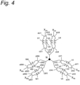
- Fig. 4 is a schematic diagram illustrating how the coils U1 to U4, V1 to V4, W1 to W4 illustrated in Fig. 3 are connected
- Fig. 3 is a top view of the stator core 10 with the upper insulator 20 removed.
- the feeder lines eU1, eU2 extend from first ends of the windings of the coils U1, U2, respectively, to connect to a U-phase connection part X Ua .
- the feeder lines eU3, eU4 extend from first ends of the windings of the coils U3, U4, respectively, to connect to a U-phase connection part X Ub .
- the feeder lines eV1, eV2 extend from first ends of the windings of the coils V1, V2, respectively, to connect to a V-phase connection part X Va .
- the feeder lines eV3, eV4 extend from first ends of the windings of the coils V3, V4, respectively, to connect to a V-phase connection part X Vb .
- the feeder lines eW1, eW2 extend from first ends of the windings of the coils W1, W2, respectively, to connect to a W-phase connection part X Wa .
- the feeder lines eW3, eW4 extend from first ends of the windings of the coils W3, W4, respectively, to connect to a W-phase connection part X Wb .
- the coils U1 to U4, V1 to V4, W1 to W4 are fixed by winding, so that the feeder lines eU1 to eU4, eV1 to eV4, eW1 to eW4 corresponding to the winding start portions do not loosen even without being fixed to the stator core 10.
- the neutral lines cU 1 to cU4 extend from second ends of the windings of the coils U1 to U4, respectively, to connect to a neutral point N.
- the neutral lines cV1 to cV4 extend from second ends of the windings of the coils V1 to V4, respectively, to connect to the neutral point N.
- the neutral lines cW1 to cW4 extend from second ends of the windings of the coils W1 to W4, respectively, to connect to the neutral point N.
- all the neutral lines cU1 to cU4, cV1 to cV4, cW1 to cW4 are electrically connected.
- the feeder lines eU1 to eU4, eV1 to eV4, eW1 to eW4 and the neutral lines cU1 to cU4, cV1 to cV4, cW1 to cW4 are latched, or secured, to the upper insulator 20 mounted to the upper end surface of the stator core 10 so as not to be electrically connected to each other.
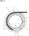
- Fig. 5 is a top view of the stator 1.
- an insulating cap 110 covering one U-phase connection part X Ua (illustrated in Figs. 3 and 4 ) and an insulating cap 120 covering the other U-phase connection part X Ub (illustrated in Figs. 3 and 4 ) are placed on their respective coil ends with the insulating cap 110 and the insulating cap 120 shifted from each other in a circumferential direction.
- an insulating cap 110 covering one V-phase connection part and an insulating cap 120 covering the other V-phase connection part are placed on their respective coil ends with the insulating cap 110 and the insulating cap 120 shifted from each other in the circumferential direction.
- an insulating cap 110 covering one W-phase connection part and an insulating cap 120 covering the W-phase connection part are placed on their respective coil ends with the insulating cap 110 and the insulating cap 120 shifted from each other in the circumferential direction.
- a lead wire 111, a lead wire 121, the insulating caps 110, the insulating caps 120, and other lead wires are fixed to the upper insulator 20 by a plurality of binding threads (not illustrated).
- Y denotes a gap between adjacent ones of the coils U1 to U4, V1 to V4, W1 to W4, and Z denotes a radial length of an opening of an upward passage in the gap Y.
- a cross-sectional area of the passage (passage cross-sectional area) in which a flow path is formed is approximately Y * Z.
- Figs. 6 and 7 are schematic cross-sectional views of an important part of the stator 1.
- Figs. 6 and 7 the same components as those illustrated in Figs. 1 and 2 are denoted by the same reference signs.
- Figs. 6 and 7 are cross-sectional views of the coil U1 among the plurality of coils U1 to U4, V1 to V4, W1 to W4, taken along a plane including the axis of the stator core 10.
- the stator 1 includes a first region S1 in which distal ends of the feeder lines eU1 to eU4, eV1 to eV4, eW1 to eW4 extending from the first ends of the plurality of coils U1 to U4, V1 to V4, W1 to W4 are connected to each other, and a second region S2 in which distal ends of the neutral lines cU1 to cU4, cV1 to cV4, cW1 to cW4 extending from the second ends of the plurality of coils U1 to U4, V1 to V4, W1 to W4 are connected to each other.
- the upper insulator 20 has an inner wall 20a and an outer wall 20b provided, spaced from each other in the radial direction of the stator core 10.
- a center of gravity O1 of the first region S1 is positioned above a center of gravity O2 of the second region S2, as seen in the axial direction of the stator core 10 (first condition).
- the center of gravity O2 of the second region S2 is positioned between the center of gravity O1 of the first region S1 and the stator core 10 (first condition).
- H a difference in height between the center of gravity O1 of the first region S1 and the center of gravity O2 of the second region S2 is denoted as H.
- the center of gravity O1 of the first region S1 here is a center of gravity of a cross-sectional shape of the first region S1
- the center of gravity O2 of the second region S2 is a center of gravity of a cross-sectional shape of the second region S2.
- satisfying the first condition and the second condition in the cross section at the gap between at least one pair of the plurality of coils U1 to U4, V1 to V4, W1 to W4, taken along the plane including the axis of the stator core 10, makes it possible to secure the passage cross-sectional area between the coils through which a refrigerant flows and thereby reduce the flow velocity of the refrigerant flowing between the coils and prevent oil from escaping through the gap between the coils.
- the cross section at the gap between the pair of coils, taken along the plane including the axis of the stator core 10, satisfies the first condition and the second condition.
- Across section at a gap between at least two coils, taken along a plane including the axis of the stator core 10, should satisfy the first condition and the second condition.
- cross sections at all gaps between adjacent ones of all the coils U1 to U4, V1 to V4, W1 to W4 taken along the plane including the axis of the stator core 10 may satisfy the first condition and the second condition.
- the center of gravity O1 of the first region S1 may be positioned above the center of gravity O2 of the second region S2, as seen in the axial direction of the stator core 10.
- the center of gravity O2 of the second region S2 may be positioned between the center of gravity O1 of the first region S1 and the stator core 10.
- the second region S2 having a relatively small cross-sectional shape is, as a whole, located below the first region S1 (i.e., closer to the stator core 10than the first region S1), so that it is possible to make a space adjacent to the coil end larger, to thereby make the flow of the refrigerant smooth while making the passage cross-sectional area between the coils larger, and thus to reduce the flow velocity of the refrigerant flowing between the coils.
- a lower end of the first region S1 is preferably positioned above an upper end of the second region S2, as seen in the axial direction of the stator core 10.
- an end remote from the stator core 10 of the second region S2 be positioned between the stator core 10 and an end adjacent to the stator core 10 of the first region S1.
- the second region S2 having a relatively small cross-sectional shape is located below the first region S1 (i.e., closer to the stator core 10 than the first region S1), so that it is possible to make the space adjacent to the coil end large, to thereby make the flow of the refrigerant smooth while making the passage cross-sectional area between the coils larger, and thus to reduce the flow velocity of the refrigerant flowing between the coils.
- the lead wire 111 and the lead wire 121 are arranged on the coils U1 to U4, V1 to V4, W1 to W4 wound around each tooth 12.
- the first region S1 including the lead wires and the second region S2 including the neutral lines vary in configuration, depending on their positions in the circumferential direction of the stator 1.
- the distal ends of the feeder lines eU1, eU2 ( Figs. 3 and 4 ) extending from the first ends of the U-phase coils U1, U2 are connected to the lead wire 111, and the distal ends of the feeder lines eU3, eU4 ( Figs. 3 and 4 ) extending from the first ends of the U-phase coils U3, U4 are connected to the lead wire 121.
- connection part X Ua ( Figs. 3 and 4 ) where the feeder lines eU1, eU2 are connected to the lead wire 111 is covered with the insulating cap 110 having a roll shape.
- connection part X Ub ( Figs. 3 and 4 ) where the feeder lines eU3, eU4 are connected to the lead wire 121 is covered with the insulating cap 120 having a roll shape.
- the feeder lines eU1, eU2, the feeder lines eU3, eU4, the lead wire 111, and the lead wire 121 are fixed to the upper insulator 20 by a binding thread (not illustrated).
- the distal ends of the neutral lines cU1, cU2 ( Figs. 3 and 4 ) extending from the second ends of the U-phase coils U1, U2 are connected to the distal ends of the neutral lines cU3, cU4 ( Figs. 3 and 4 ) extending from the second ends of the U-phase coils U3, U4.
- Fig. 8 is a schematic cross-sectional view of an important part of a stator 1 of a second embodiment of the present disclosure.
- a radial length from a radially innermost end to a radially outermost end of an aggregation of four first regions S1 is denoted as La
- a radial length from a radially innermost end to a radially outermost end of an aggregation of two second regions S2 is denoted as Lb
- Lb a relationship of La > Lb is satisfied.
- the stator of the second embodiment has the same effects as the stator 1 of the first embodiment.
- the present disclosure is applicable to not only the stator including the four first regions S1 and the two second regions S2 illustrated in Fig. 8 , but also a stator including a plurality of first regions S1 and at least one second region S2.
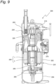
- Fig. 9 is a cross-sectional view of a compressor 200 including a motor 240 of a third embodiment of the present disclosure.
- This compressor is a scroll compressor.
- the compressor 200 of the third embodiment includes a hermetic container 201, a compression mechanism part 230 including a fixed scroll 210 and a movable scroll 220, a motor 240 that drives the compression mechanism part 230, a crankshaft 250 that connects the compression mechanism part 230 to the motor 240, and a lower bearing 260 that rotatably supports a lower end of the crankshaft 250.
- the hermetic container 201 includes a cylindrical member 202 that has a substantially cylindrical shape and is vertically opened, and an upper lid 203 and a lower lid 204 respectively provided at an upper end and a lower end of the cylindrical member 202.
- the motor 240 includes the stator 1 of the first embodiment and a rotor 2 disposed radially inside of the stator 1.
- the motor 240 is of an inner rotor type and is a so-called 8-pole 12-slot motor. Note that the number of poles of the motor and the number of slots of the motor are not limited to those described above.
- a plurality of lead wires from the stator 1 are connected to terminals of a terminal part 270 provided on the cylindrical member 202 of the hermetic container 201.
- An electromagnetic force produced in the stator 1 by applying a current to the coils U1 to U4, V1 to V4, W1 to W4 ( Figs. 3 and 4 ) of the stator 1 of the motor 240 causes the rotor 2 to rotate together with the crankshaft 250.
- stator 1 of the first embodiment allows an increase in reliability of the motor 240 of the third embodiment. This makes the compressor 200 highly reliable.
- the scroll compressor has been described.
- the motor of the present disclosure may be applied to a compressor having another configuration such as a rotary compressor.
- stator in which a three-phase AC voltage is applied to the coils has been described.
- present disclosure may be applied to stators in which a two-phase or four- or more phase AC voltage is applied to the coils.
Landscapes
- Engineering & Computer Science (AREA)
- Power Engineering (AREA)
- Mechanical Engineering (AREA)
- General Engineering & Computer Science (AREA)
- Physics & Mathematics (AREA)
- Thermal Sciences (AREA)
- Compressor (AREA)
- Insulation, Fastening Of Motor, Generator Windings (AREA)
- Windings For Motors And Generators (AREA)
Abstract
Description
- The present disclosure relates to a stator, a motor, and a compressor.
- A known stator has neutral lines and lead wires fixed to an upper insulator, with the neutral lines and the lead wires not orderly separated from each other and from coils (see, for example,
JP 3824001 B2 - Patent Literature 1:
JP 3824001 B2 - When the stator described above is used in a motor disposed in a hermetic container of a compressor, the neutral lines and the lead wires prevent an enough gap from being provided between the coils, so that a cross-sectional area of a passage between the coils through which a refrigerant flows becomes insufficient, causing oil to be discharged along with the refrigerant due to an increase in flow velocity of the refrigerant flowing between the coils, thus escape of oil from the compressor cannot be prevented accordingly.
- The present disclosure proposes a stator capable of preventing oil from escaping, or leaking, through a gap between coils when used in a motor of a compressor.
- The present disclosure further provides a motor including the stator.
- The present disclosure further provides a compressor including the motor.
- A stator of the present disclosure includes:
- a stator core having a plurality of teeth;
- an insulator mounted to an axially end surface of the stator core;
- a plurality of coils each wound around a corresponding one of the plurality of teeth of the stator core;
- a first region in which a distal end of a feeder line extending from a first end of a said coil is connected to a distal end of a feeder line extending from a first end of another said coil; and
- a second region in which distal ends of neutral lines extending from second ends of the coils are connected to each other.
- The insulator has an inner wall and an outer wall provided, spaced from each other in a radial direction of the stator core, and
- in a cross section at a gap between at least two adjacent coils among the plurality of coils taken along a plane including an axis of the stator core, a center of gravity of the second region is positioned between a center of gravity of the first region and the stator core, and assuming that a radial length of the first region is B, a radial length of the second region is C, and that a radial length between the inner wall and the outer wall of the insulator is A, a relationship of

- According to the present disclosure, satisfying the condition that the center of gravity of the second region is positioned between the center of gravity of the first region and the stator core and the condition of the
expression 1 makes it possible to secure a sufficient cross-sectional area of a passage between at least two coils through which a refrigerant flows when the stator is used in a motor of a compressor, to thereby reduce a flow velocity of the refrigerant flowing between the coils, and eventually to prevent oil from escaping through the gap between the coils. - In the stator according to one aspect of the present disclosure, in cross sections at gaps between all the coils taken along respective planes including the axis of the stator core, the center of gravity of the second region is positioned between the center of gravity of the first region and the stator core, and the relationship of the
expression 1 is satisfied. - According to the present disclosure, when the stator is used in a motor of a compressor, it is possible to secure passages of a sufficient cross-sectional area between all the coils through which a refrigerant flows, to reduce a flow velocity of the refrigerant flowing between the coils, and to prevent oil from escaping through the gaps between the coils.
- In the stator according to one aspect of the present disclosure, in a cross section of the stator core taken along a plane including the axis of the stator core and passing any point of a circumference of the stator core, the center of gravity of the second region is positioned between the center of gravity of the first region and the stator core.
- According to the present disclosure, the second region, which has a relatively small cross-sectional shape, is, as a whole, located closer to the stator core than the first region. Therefore, it is possible to make a space adjacent to a coil end larger, to thereby make the flow of the refrigerant smooth while making the cross-sectional area of the passage between the coils larger, and reduce the flow velocity of the refrigerant flowing between the coils.
- In the stator according to one aspect of the present disclosure, an end remote from the stator core of the second region is positioned between the stator core and an end adjacent to the stator core of the first region.
- According to the present disclosure, the second region, which has a relatively small cross-sectional shape, is located closer to the stator core than the first region, so that it is possible to make a space adjacent to a coil end larger, and to thereby make the flow of the refrigerant smooth while making the cross-sectional area of the passage between the coils larger, and reduce the flow velocity of the refrigerant flowing between the coils.
- In the stator according to one aspect of the present disclosure, there are a plurality of first regions and one or more second regions, and
in cross sections at gaps between all the coils taken along respective planes including the axis of the stator core, when a radial length from a radially innermost end to a radially outermost end of the plurality of first regions is denoted as La, and a radial length from a radially innermost end to a radially outermost end of the one or more second regions is denoted as Lb, a relationship of
- According to the present disclosure, satisfying the relationship of the
expression 2 makes it possible to secure the cross-sectional area of the passage between coils through which the refrigerant flows when the stator is used in a motor of a compressor. - A motor of the present disclosure includes:
- the stator according to any one of the above aspects; and
- a rotor disposed radially inside of the stator.
- According to the present disclosure, it is possible to provide a highly reliable motor.
- A compressor of the present disclosure includes:
- a hermetic container;
- a compression mechanism part disposed in the hermetic container; and
- the motor disposed in the hermetic container and configured to drive the compression mechanism part.
- According to the present disclosure, it is possible to provide a compressor including a highly reliable motor.
-
-
Fig. 1 is a perspective view of a stator of a first embodiment of the present disclosure. -
Fig. 2 is a longitudinal cross-sectional view of the stator. -
Fig. 3 is a diagram illustrating how coils of the stator are connected. -
Fig. 4 is a schematic diagram illustrating how the coils illustrated inFig. 3 are connected. -
Fig. 5 is a top view of the stator. -
Fig. 6 is a schematic cross-sectional view of an important part of the stator. -
Fig. 7 is a schematic cross-sectional view of the part of the stator. -
Fig. 8 is a schematic cross-sectional view of an important part of a stator of a second embodiment of the present disclosure. -
Fig. 9 is a cross-sectional view of a compressor including a motor of a third embodiment of the present disclosure. - Embodiments will be described below. It should be noted that in the drawings, the same reference numerals represent the same or corresponding parts. In addition, the dimensions on the drawings, such as lengths, widths, thicknesses, and depths, are appropriately changed from actual scales for clarity and simplification of the drawings, and do not represent actual relative dimensions.
-
Fig. 1 is a perspective view of astator 1 of a first embodiment of the present disclosure, andFig. 2 is a longitudinal cross-sectional view of the stator. - As illustrated in
Figs. 1 and2 , thestator 1 has astator core 10, anupper insulator 20 mounted to an axially upper end surface of thestator core 10, alower insulator 30 mounted to an axially lower end surface of thestator core 10, and coils U1 to U4, V1 to V4, W1 to W4 wound around thestator core 10, theupper insulator 20, and thelower insulator 30 as assembled together. - The
upper insulator 20 and thelower insulator 30 are made of an insulating resin. - The
stator core 10 has aback yoke 11 having an annular shape, and a plurality ofteeth 12 protruding radially inward from an inner peripheral surface of theback yoke 11. - The coils U1 to U4, V1 to V4, W1 to W4 are each wound around a corresponding one of the
teeth 12 rather than being distributedly wound around theteeth 12, which is a so-called concentrated winding. -
Fig. 3 is a diagram illustrating how the coils U1 to U4, V1 to V4, W1 to W4 of thestator 1 are connected, andFig. 4 is a schematic diagram illustrating how the coils U1 to U4, V1 to V4, W1 to W4 illustrated inFig. 3 are connected.Fig. 3 is a top view of thestator core 10 with theupper insulator 20 removed. - Twelve feeder lines eU1 to eU4, eV1 to eV4, eW1 to eW4 corresponding to winding start portions of windings of the coils U1 to U4, V1 to V4, W1 to W4, respectively, emerge from the upper end surface of the
stator core 10. Twelve neutral lines cU1 to cU4, cV1 to cV4, cW1 to cW4 corresponding to winding end portions of the windings of the coils U1 to U4, V1 to V4, W1 to W4, respectively, also emerge from the upper end surface of thestator core 10. - The feeder lines eU1, eU2 extend from first ends of the windings of the coils U1, U2, respectively, to connect to a U-phase connection part XUa. The feeder lines eU3, eU4 extend from first ends of the windings of the coils U3, U4, respectively, to connect to a U-phase connection part XUb.
- The feeder lines eV1, eV2 extend from first ends of the windings of the coils V1, V2, respectively, to connect to a V-phase connection part XVa. The feeder lines eV3, eV4 extend from first ends of the windings of the coils V3, V4, respectively, to connect to a V-phase connection part XVb.
- The feeder lines eW1, eW2 extend from first ends of the windings of the coils W1, W2, respectively, to connect to a W-phase connection part XWa. The feeder lines eW3, eW4 extend from first ends of the windings of the coils W3, W4, respectively, to connect to a W-phase connection part XWb.
- The coils U1 to U4, V1 to V4, W1 to W4 are fixed by winding, so that the feeder lines eU1 to eU4, eV1 to eV4, eW1 to eW4 corresponding to the winding start portions do not loosen even without being fixed to the
stator core 10. - The
neutral lines cU 1 to cU4 extend from second ends of the windings of the coils U1 to U4, respectively, to connect to a neutral point N. The neutral lines cV1 to cV4 extend from second ends of the windings of the coils V1 to V4, respectively, to connect to the neutral point N. The neutral lines cW1 to cW4 extend from second ends of the windings of the coils W1 to W4, respectively, to connect to the neutral point N. At the neutral point N, all the neutral lines cU1 to cU4, cV1 to cV4, cW1 to cW4 are electrically connected. - The feeder lines eU1 to eU4, eV1 to eV4, eW1 to eW4 and the neutral lines cU1 to cU4, cV1 to cV4, cW1 to cW4 are latched, or secured, to the
upper insulator 20 mounted to the upper end surface of thestator core 10 so as not to be electrically connected to each other. -
Fig. 5 is a top view of thestator 1. As illustrated inFig. 5 , an insulatingcap 110 covering one U-phase connection part XUa (illustrated inFigs. 3 and4 ) and aninsulating cap 120 covering the other U-phase connection part XUb (illustrated inFigs. 3 and4 ) are placed on their respective coil ends with the insulatingcap 110 and theinsulating cap 120 shifted from each other in a circumferential direction. - Likewise, an insulating
cap 110 covering one V-phase connection part and aninsulating cap 120 covering the other V-phase connection part are placed on their respective coil ends with the insulatingcap 110 and theinsulating cap 120 shifted from each other in the circumferential direction. - Likewise, an insulating
cap 110 covering one W-phase connection part and aninsulating cap 120 covering the W-phase connection part are placed on their respective coil ends with the insulatingcap 110 and theinsulating cap 120 shifted from each other in the circumferential direction. - A
lead wire 111, alead wire 121, the insulatingcaps 110, the insulatingcaps 120, and other lead wires are fixed to theupper insulator 20 by a plurality of binding threads (not illustrated). - In
Fig. 5 , Y denotes a gap between adjacent ones of the coils U1 to U4, V1 to V4, W1 to W4, and Z denotes a radial length of an opening of an upward passage in the gap Y. A cross-sectional area of the passage (passage cross-sectional area) in which a flow path is formed is approximately Y * Z. -
Figs. 6 and7 are schematic cross-sectional views of an important part of thestator 1. InFigs. 6 and7 , the same components as those illustrated inFigs. 1 and2 are denoted by the same reference signs.Figs. 6 and7 are cross-sectional views of the coil U1 among the plurality of coils U1 to U4, V1 to V4, W1 to W4, taken along a plane including the axis of thestator core 10. - The
stator 1 includes a first region S1 in which distal ends of the feeder lines eU1 to eU4, eV1 to eV4, eW1 to eW4 extending from the first ends of the plurality of coils U1 to U4, V1 to V4, W1 to W4 are connected to each other, and a second region S2 in which distal ends of the neutral lines cU1 to cU4, cV1 to cV4, cW1 to cW4 extending from the second ends of the plurality of coils U1 to U4, V1 to V4, W1 to W4 are connected to each other. - The
upper insulator 20 has aninner wall 20a and anouter wall 20b provided, spaced from each other in the radial direction of thestator core 10. - In the cross section illustrated in
Fig. 6 , a center of gravity O1 of the first region S1 is positioned above a center of gravity O2 of the second region S2, as seen in the axial direction of the stator core 10 (first condition). In other words, in the cross section illustrated inFig. 6 , the center of gravity O2 of the second region S2 is positioned between the center of gravity O1 of the first region S1 and the stator core 10 (first condition). In the first embodiment, a difference in height between the center of gravity O1 of the first region S1 and the center of gravity O2 of the second region S2 is denoted as H. The center of gravity O1 of the first region S1 here is a center of gravity of a cross-sectional shape of the first region S1, and the center of gravity O2 of the second region S2 is a center of gravity of a cross-sectional shape of the second region S2. - In the cross section illustrated in
Fig. 7 , when a radial length of the first region S1 is denoted as B, a radial length of the second region S2 is denoted as C, and a radial length between theinner wall 20a and theouter wall 20b of theupper insulator 20 is denoted as A, a relationship of
- When the stator is used in a
compressor 200, as described later, satisfying the first condition and the second condition in the cross section at the gap between at least one pair of the plurality of coils U1 to U4, V1 to V4, W1 to W4, taken along the plane including the axis of thestator core 10, makes it possible to secure the passage cross-sectional area between the coils through which a refrigerant flows and thereby reduce the flow velocity of the refrigerant flowing between the coils and prevent oil from escaping through the gap between the coils. - In the first embodiment, the cross section at the gap between the pair of coils, taken along the plane including the axis of the
stator core 10, satisfies the first condition and the second condition. Across section at a gap between at least two coils, taken along a plane including the axis of thestator core 10, should satisfy the first condition and the second condition. - Alternatively, cross sections at all gaps between adjacent ones of all the coils U1 to U4, V1 to V4, W1 to W4 taken along the plane including the axis of the
stator core 10 may satisfy the first condition and the second condition. This makes it possible to secure the passage cross-sectional areas between all the coils U1 to U4, V1 to V4, W1 to W4, to reduce the flow velocity of the refrigerant flowing between all the coils U1 to U4, V1 to V4, W1 to W4, and thus to prevent an outflow of the oil from the gap between the coils U1 to U4, V1 to V4, W1 to W4. - In a cross section of the
stator core 10, taken along a plane including the axis of thestator core 10, at any point of the circumference of thestator core 10, the center of gravity O1 of the first region S1 may be positioned above the center of gravity O2 of the second region S2, as seen in the axial direction of thestator core 10. In other words, in a cross section of thestator core 10, taken along a plane including the axis of thestator core 10 and passing any point of the circumference of thestator core 10, the center of gravity O2 of the second region S2 may be positioned between the center of gravity O1 of the first region S1 and thestator core 10. As a result, the second region S2 having a relatively small cross-sectional shape is, as a whole, located below the first region S1 (i.e., closer to the stator core 10than the first region S1), so that it is possible to make a space adjacent to the coil end larger, to thereby make the flow of the refrigerant smooth while making the passage cross-sectional area between the coils larger, and thus to reduce the flow velocity of the refrigerant flowing between the coils. - A lower end of the first region S1 is preferably positioned above an upper end of the second region S2, as seen in the axial direction of the
stator core 10. In other words, it is preferable that an end remote from thestator core 10 of the second region S2 be positioned between thestator core 10 and an end adjacent to thestator core 10 of the first region S1. As a result, the second region S2 having a relatively small cross-sectional shape is located below the first region S1 (i.e., closer to thestator core 10 than the first region S1), so that it is possible to make the space adjacent to the coil end large, to thereby make the flow of the refrigerant smooth while making the passage cross-sectional area between the coils larger, and thus to reduce the flow velocity of the refrigerant flowing between the coils. - Next, details of the first region S1 and the second region S2 will be described.
- First, in a top view of the
stator 1 illustrated inFig. 5 , thelead wire 111 and thelead wire 121 are arranged on the coils U1 to U4, V1 to V4, W1 to W4 wound around eachtooth 12. The first region S1 including the lead wires and the second region S2 including the neutral lines vary in configuration, depending on their positions in the circumferential direction of thestator 1. - For example, in the first region S1 at a certain position in the circumferential direction of the
stator 1, the distal ends of the feeder lines eU1, eU2 (Figs. 3 and4 ) extending from the first ends of the U-phase coils U1, U2 are connected to thelead wire 111, and the distal ends of the feeder lines eU3, eU4 (Figs. 3 and4 ) extending from the first ends of the U-phase coils U3, U4 are connected to thelead wire 121. - Note that the connection part XUa (
Figs. 3 and4 ) where the feeder lines eU1, eU2 are connected to thelead wire 111 is covered with the insulatingcap 110 having a roll shape. Note that the connection part XUb (Figs. 3 and4 ) where the feeder lines eU3, eU4 are connected to thelead wire 121 is covered with the insulatingcap 120 having a roll shape. - The feeder lines eU1, eU2, the feeder lines eU3, eU4, the
lead wire 111, and thelead wire 121 are fixed to theupper insulator 20 by a binding thread (not illustrated). - In the second region S2, the distal ends of the neutral lines cU1, cU2 (
Figs. 3 and4 ) extending from the second ends of the U-phase coils U1, U2 are connected to the distal ends of the neutral lines cU3, cU4 (Figs. 3 and4 ) extending from the second ends of the U-phase coils U3, U4. -
Fig. 8 is a schematic cross-sectional view of an important part of astator 1 of a second embodiment of the present disclosure. As illustrated inFig. 8 , in the cross section at the gap between adjacent ones of all the coils U1 to U4, V1 to V4, W1 to W4 taken along the plane including the axis of thestator core 10, when a radial length from a radially innermost end to a radially outermost end of an aggregation of four first regions S1 is denoted as La, and a radial length from a radially innermost end to a radially outermost end of an aggregation of two second regions S2 is denoted as Lb, a relationship of
- Satisfying the relationship of the
expression 2 makes it possible to secure a passage cross-sectional area between the coils through which a refrigerant flows when the stator is used in a motor of a compressor. - The stator of the second embodiment has the same effects as the
stator 1 of the first embodiment. - The present disclosure is applicable to not only the stator including the four first regions S1 and the two second regions S2 illustrated in
Fig. 8 , but also a stator including a plurality of first regions S1 and at least one second region S2. -
Fig. 9 is a cross-sectional view of acompressor 200 including amotor 240 of a third embodiment of the present disclosure. This compressor is a scroll compressor. - As illustrated in
Fig. 9 , thecompressor 200 of the third embodiment includes ahermetic container 201, acompression mechanism part 230 including a fixedscroll 210 and amovable scroll 220, amotor 240 that drives thecompression mechanism part 230, acrankshaft 250 that connects thecompression mechanism part 230 to themotor 240, and alower bearing 260 that rotatably supports a lower end of thecrankshaft 250. - The
hermetic container 201 includes acylindrical member 202 that has a substantially cylindrical shape and is vertically opened, and anupper lid 203 and alower lid 204 respectively provided at an upper end and a lower end of thecylindrical member 202. - The
motor 240 includes thestator 1 of the first embodiment and arotor 2 disposed radially inside of thestator 1. Themotor 240 is of an inner rotor type and is a so-called 8-pole 12-slot motor. Note that the number of poles of the motor and the number of slots of the motor are not limited to those described above. - In the
motor 240, a plurality of lead wires from thestator 1 are connected to terminals of aterminal part 270 provided on thecylindrical member 202 of thehermetic container 201. - An electromagnetic force produced in the
stator 1 by applying a current to the coils U1 to U4, V1 to V4, W1 to W4 (Figs. 3 and4 ) of thestator 1 of themotor 240 causes therotor 2 to rotate together with thecrankshaft 250. - The use of the
stator 1 of the first embodiment allows an increase in reliability of themotor 240 of the third embodiment. This makes thecompressor 200 highly reliable. - In the third embodiment, the scroll compressor has been described. Alternatively, the motor of the present disclosure may be applied to a compressor having another configuration such as a rotary compressor.
- In the first to third embodiments, the stator in which a three-phase AC voltage is applied to the coils has been described. Alternatively, the present disclosure may be applied to stators in which a two-phase or four- or more phase AC voltage is applied to the coils.
- Although specific embodiments of the present disclosure have been described, the present disclosure is not limited to the first to third embodiments, and various modifications can be made within the scope of the present disclosure.
-
- 1
- stator
- 2
- rotor
- 11
- back yoke
- 12
- tooth
- 10
- stator core
- 20
- upper insulator
- 30
- lower insulator
- 110
- insulating cap
- 111
- lead wire
- 120
- insulating cap
- 121
- lead wire
- 200
- compressor
- 201
- hermetic container
- 210
- fixed scroll
- 220
- movable scroll
- 230
- compression mechanism part
- 240
- motor
- 250
- crankshaft
- 260
- lower bearing
- 270
- terminal part
- cU1 to cU4, cV1 to cV4, cW1 to cW4
- neutral line
- eU1 to eU4, eV1 to eV4, eW1 to eW4
- feeder line
- U1 to U4, V1 to V4, W1 to W4
- coil
- XUa, XVa, XWa
- connection part
- XUb, XVb, XWb
- connection part
Claims (7)
- A stator comprising:a stator core (10) having a plurality of teeth (12);an insulator (20) mounted to an axially end surface of the stator core (10);a plurality of coils (U1 to U4, V1 to V4, W1 to W4) each wound around a corresponding one of the plurality of teeth (12) of the stator core (10);a first region (S1) in which a distal end of a feeder line (eU1 to eU4, eV1 to eV4, eW1 to eW4) extending from a first end of a said coil (U1 to U4, V1 to V4, W1 to W4) is connected to a distal end of a feeder line (eU1 to eU4, eV1 to eV4, eW1 to eW4) extending from a first end of another said coil (U1 to U4, V1 to V4, W1 to W4); anda second region (S2) in which distal ends of neutral lines (cU1 to cU4, cV1 to cV4, cW1 to cW4) extending from second ends of the coils (U1 to U4, V1 to V4, W1 to W4) are connected to each other,wherein the insulator (20) has an inner wall (20a) and an outer wall (20b) provided, spaced from each other in a radial direction of the stator core (10), andin a cross section at a gap between at least two adjacent coils among the plurality of coils (U1 to U4, V1 to V4, W1 to W4), taken along a plane including an axis of the stator core (10), a center of gravity (O2) of the second region (S2) is positioned between a center of gravity (O1) of the first region (S1) and the stator core (10), and assuming that a radial length of the first region (S1) is B, a radial length of the second region (S2) is C, and that a radial length between the inner wall (20a) and the outer wall (20b) of the insulator (20) is A, a relationship of

- The stator according to claim 1, wherein in cross sections at gaps between all the coils (U1 to U4, V1 to V4, W1 to W4) taken along respective planes including the axis of the stator core (10), the center of gravity (O2) of the second region (S2) is positioned between the center of gravity (O1) of the first region (S1) and the stator core (10), and the relationship of the expression 1 is satisfied.
- The stator according to claim 1, wherein in a cross section of the stator core (10) taken along a plane including the axis of the stator core (10) and passing any point of a circumference of the stator core (10), the center of gravity (O2) of the second region (S2) is positioned between the center of gravity (O1) of the first region (S1) and the stator core (10).
- The stator according to any one of claims 1 to 3, wherein an end, remote from the stator core (10), of the second region (S2) is positioned between the stator core (10) and an end, adjacent to the stator core (10), of the first region (S1).
- The stator according to any one of claims 1 to 4, whereinthe stator includes a plurality of first regions (S1), and one or more second regions (S2), andin cross sections at gaps between all the coils (U1 to U4, V1 to V4, W1 to W4) taken along respective planes including the axis of the stator core (10), assuming that a radial length from a radially innermost end to a radially outermost end of the plurality of first regions (S1) is La, and a radial length from a radially innermost end to a radially outermost end of the one or more second regions (S2) is Lb, a relationship of

- A motor comprising:the stator (1) according to any one of claims 1 to 5; anda rotor (2) disposed radially inside of the stator (1).
- A compressor comprising:a hermetic container (201);a compression mechanism part (230) disposed in the hermetic container (201); andthe motor (240) according to claim 6, the motor (240) being disposed in the hermetic container (201) and configured to drive the compression mechanism part (230).
Applications Claiming Priority (2)
| Application Number | Priority Date | Filing Date | Title |
|---|---|---|---|
| JP2020127325A JP7089195B2 (en) | 2020-07-28 | 2020-07-28 | Stator, motor and compressor |
| PCT/JP2021/018660 WO2022024503A1 (en) | 2020-07-28 | 2021-05-17 | Stator, motor, and compressor |
Publications (2)
| Publication Number | Publication Date |
|---|---|
| EP4164094A1 true EP4164094A1 (en) | 2023-04-12 |
| EP4164094A4 EP4164094A4 (en) | 2023-11-29 |
Family
ID=80037985
Family Applications (1)
| Application Number | Title | Priority Date | Filing Date |
|---|---|---|---|
| EP21849142.1A Withdrawn EP4164094A4 (en) | 2020-07-28 | 2021-05-17 | STATOR, MOTOR AND COMPRESSOR |
Country Status (5)
| Country | Link |
|---|---|
| US (1) | US11837932B2 (en) |
| EP (1) | EP4164094A4 (en) |
| JP (1) | JP7089195B2 (en) |
| CN (1) | CN115917929B (en) |
| WO (1) | WO2022024503A1 (en) |
Family Cites Families (14)
| Publication number | Priority date | Publication date | Assignee | Title |
|---|---|---|---|---|
| JP3824001B2 (en) | 2004-02-06 | 2006-09-20 | ダイキン工業株式会社 | Electric motor stator |
| US7701102B2 (en) | 2004-02-06 | 2010-04-20 | Daikin Industries, Ltd. | Electric motor stator |
| JP2008061407A (en) * | 2006-08-31 | 2008-03-13 | Jtekt Corp | Electric motor |
| JP2010213527A (en) * | 2009-03-12 | 2010-09-24 | Daikin Ind Ltd | Stator, motor, and compressor |
| WO2011007881A1 (en) * | 2009-07-17 | 2011-01-20 | ダイキン工業株式会社 | Stator, motor, and compressor |
| JP5938903B2 (en) * | 2011-12-28 | 2016-06-22 | 株式会社富士通ゼネラル | Electric motor |
| JP2014195384A (en) * | 2013-03-29 | 2014-10-09 | Mitsubishi Electric Corp | Motor for compressor, compressor, and refrigeration cycle device |
| JP6267907B2 (en) * | 2013-09-26 | 2018-01-24 | 株式会社ミツバ | Busbar unit and brushless motor |
| JP5988005B1 (en) | 2015-04-16 | 2016-09-07 | ダイキン工業株式会社 | Stator and motor and compressor having the same |
| DE112017000703B4 (en) * | 2016-02-08 | 2026-02-12 | Nidec Corporation | Stator, motor and compressor |
| CN110692179B (en) * | 2017-06-29 | 2022-06-07 | 日本电产株式会社 | Stator, motor, and method for manufacturing stator |
| WO2019065141A1 (en) * | 2017-09-29 | 2019-04-04 | 日本電産株式会社 | Stator, motor, compressor and method for manufacturing stator |
| KR102522992B1 (en) | 2018-04-17 | 2023-04-18 | 엘지전자 주식회사 | Insulator of stator and stator |
| JP7283049B2 (en) * | 2018-10-31 | 2023-05-30 | 株式会社富士通ゼネラル | compressor |
-
2020
- 2020-07-28 JP JP2020127325A patent/JP7089195B2/en active Active
-
2021
- 2021-05-17 CN CN202180043711.5A patent/CN115917929B/en active Active
- 2021-05-17 WO PCT/JP2021/018660 patent/WO2022024503A1/en not_active Ceased
- 2021-05-17 EP EP21849142.1A patent/EP4164094A4/en not_active Withdrawn
-
2023
- 2023-01-23 US US18/100,405 patent/US11837932B2/en active Active
Also Published As
| Publication number | Publication date |
|---|---|
| WO2022024503A1 (en) | 2022-02-03 |
| JP2022024625A (en) | 2022-02-09 |
| US11837932B2 (en) | 2023-12-05 |
| CN115917929A (en) | 2023-04-04 |
| US20230155442A1 (en) | 2023-05-18 |
| EP4164094A4 (en) | 2023-11-29 |
| CN115917929B (en) | 2025-02-14 |
| JP7089195B2 (en) | 2022-06-22 |
Similar Documents
| Publication | Publication Date | Title |
|---|---|---|
| US10305339B2 (en) | Rotating electrical machine and method of manufacturing the same | |
| US8461738B2 (en) | Single-layer coil with one bent endwinding and one straight endwinding | |
| EP1713158B1 (en) | Stator of motor | |
| JP2014107983A (en) | Electric motor | |
| WO2019073724A1 (en) | Stator of rotating electric machine | |
| EP1713157B1 (en) | Electric motor stator | |
| JP2017163825A (en) | Motor and its stator | |
| EP3116101A1 (en) | Armature core, armature, and electric motor | |
| JP2006187073A (en) | Insulator, stator and motor | |
| US12142981B2 (en) | Stator provided with insulating paper, motor having stator, and method for manufacturing motor | |
| CN111668962B (en) | Armature | |
| EP3598612B1 (en) | Stator and electric motor equipped with said stator | |
| EP3687042A1 (en) | Insulator, and stator and motor comprising same | |
| JP6496229B2 (en) | Rotating electric machine | |
| US11837932B2 (en) | Stator, motor, and compressor | |
| JP2009213343A (en) | Stator | |
| WO2019003674A1 (en) | Dynamo-electric machine | |
| JP2021035260A (en) | Stator | |
| EP4366139A1 (en) | Rotating electric machine | |
| JP7093028B2 (en) | Stator, motor and compressor | |
| JP5660402B2 (en) | Rotating electric machine | |
| CN109802499B (en) | Stator of rotating electric machine and rotating electric machine | |
| JP2008182790A (en) | Insulating paper and stator | |
| JP7275211B2 (en) | Insulator, stator, and rotary electric machine using them | |
| JP2008043005A (en) | Buzz bar for rotating electrical machines |
Legal Events
| Date | Code | Title | Description |
|---|---|---|---|
| STAA | Information on the status of an ep patent application or granted ep patent |
Free format text: STATUS: THE INTERNATIONAL PUBLICATION HAS BEEN MADE |
|
| PUAI | Public reference made under article 153(3) epc to a published international application that has entered the european phase |
Free format text: ORIGINAL CODE: 0009012 |
|
| STAA | Information on the status of an ep patent application or granted ep patent |
Free format text: STATUS: REQUEST FOR EXAMINATION WAS MADE |
|
| 17P | Request for examination filed |
Effective date: 20230105 |
|
| AK | Designated contracting states |
Kind code of ref document: A1 Designated state(s): AL AT BE BG CH CY CZ DE DK EE ES FI FR GB GR HR HU IE IS IT LI LT LU LV MC MK MT NL NO PL PT RO RS SE SI SK SM TR |
|
| P01 | Opt-out of the competence of the unified patent court (upc) registered |
Effective date: 20230525 |
|
| REG | Reference to a national code |
Ref country code: DE Ref legal event code: R079 Free format text: PREVIOUS MAIN CLASS: H02K0003180000 Ipc: F04B0039000000 |
|
| DAV | Request for validation of the european patent (deleted) | ||
| DAX | Request for extension of the european patent (deleted) | ||
| A4 | Supplementary search report drawn up and despatched |
Effective date: 20231027 |
|
| RIC1 | Information provided on ipc code assigned before grant |
Ipc: F04B 39/12 20060101ALI20231023BHEP Ipc: F04B 39/02 20060101ALI20231023BHEP Ipc: F04B 35/04 20060101ALI20231023BHEP Ipc: H02K 3/52 20060101ALI20231023BHEP Ipc: F04B 39/00 20060101AFI20231023BHEP |
|
| RAP3 | Party data changed (applicant data changed or rights of an application transferred) |
Owner name: DAIKIN INDUSTRIES, LTD. |
|
| GRAP | Despatch of communication of intention to grant a patent |
Free format text: ORIGINAL CODE: EPIDOSNIGR1 |
|
| STAA | Information on the status of an ep patent application or granted ep patent |
Free format text: STATUS: GRANT OF PATENT IS INTENDED |
|
| RIC1 | Information provided on ipc code assigned before grant |
Ipc: F04B 39/12 20060101ALI20240607BHEP Ipc: F04B 39/02 20060101ALI20240607BHEP Ipc: F04B 35/04 20060101ALI20240607BHEP Ipc: H02K 3/52 20060101ALI20240607BHEP Ipc: F04B 39/00 20060101AFI20240607BHEP |
|
| INTG | Intention to grant announced |
Effective date: 20240703 |
|
| STAA | Information on the status of an ep patent application or granted ep patent |
Free format text: STATUS: THE APPLICATION IS DEEMED TO BE WITHDRAWN |
|
| 18D | Application deemed to be withdrawn |
Effective date: 20241105 |