EP4164032A1 - Battery pack lower case and battery pack - Google Patents
Battery pack lower case and battery pack Download PDFInfo
- Publication number
- EP4164032A1 EP4164032A1 EP22755605.7A EP22755605A EP4164032A1 EP 4164032 A1 EP4164032 A1 EP 4164032A1 EP 22755605 A EP22755605 A EP 22755605A EP 4164032 A1 EP4164032 A1 EP 4164032A1
- Authority
- EP
- European Patent Office
- Prior art keywords
- battery pack
- liner
- lower case
- beams
- case according
- Prior art date
- Legal status (The legal status is an assumption and is not a legal conclusion. Google has not performed a legal analysis and makes no representation as to the accuracy of the status listed.)
- Pending
Links
Images


Classifications
-
- H—ELECTRICITY
- H01—ELECTRIC ELEMENTS
- H01M—PROCESSES OR MEANS, e.g. BATTERIES, FOR THE DIRECT CONVERSION OF CHEMICAL ENERGY INTO ELECTRICAL ENERGY
- H01M50/00—Constructional details or processes of manufacture of the non-active parts of electrochemical cells other than fuel cells, e.g. hybrid cells
- H01M50/20—Mountings; Secondary casings or frames; Racks, modules or packs; Suspension devices; Shock absorbers; Transport or carrying devices; Holders
- H01M50/233—Mountings; Secondary casings or frames; Racks, modules or packs; Suspension devices; Shock absorbers; Transport or carrying devices; Holders characterised by physical properties of casings or racks, e.g. dimensions
- H01M50/242—Mountings; Secondary casings or frames; Racks, modules or packs; Suspension devices; Shock absorbers; Transport or carrying devices; Holders characterised by physical properties of casings or racks, e.g. dimensions adapted for protecting batteries against vibrations, collision impact or swelling
-
- H—ELECTRICITY
- H01—ELECTRIC ELEMENTS
- H01M—PROCESSES OR MEANS, e.g. BATTERIES, FOR THE DIRECT CONVERSION OF CHEMICAL ENERGY INTO ELECTRICAL ENERGY
- H01M50/00—Constructional details or processes of manufacture of the non-active parts of electrochemical cells other than fuel cells, e.g. hybrid cells
- H01M50/20—Mountings; Secondary casings or frames; Racks, modules or packs; Suspension devices; Shock absorbers; Transport or carrying devices; Holders
- H01M50/204—Racks, modules or packs for multiple batteries or multiple cells
-
- H—ELECTRICITY
- H01—ELECTRIC ELEMENTS
- H01M—PROCESSES OR MEANS, e.g. BATTERIES, FOR THE DIRECT CONVERSION OF CHEMICAL ENERGY INTO ELECTRICAL ENERGY
- H01M50/00—Constructional details or processes of manufacture of the non-active parts of electrochemical cells other than fuel cells, e.g. hybrid cells
- H01M50/20—Mountings; Secondary casings or frames; Racks, modules or packs; Suspension devices; Shock absorbers; Transport or carrying devices; Holders
- H01M50/244—Secondary casings; Racks; Suspension devices; Carrying devices; Holders characterised by their mounting method
-
- H—ELECTRICITY
- H01—ELECTRIC ELEMENTS
- H01M—PROCESSES OR MEANS, e.g. BATTERIES, FOR THE DIRECT CONVERSION OF CHEMICAL ENERGY INTO ELECTRICAL ENERGY
- H01M50/00—Constructional details or processes of manufacture of the non-active parts of electrochemical cells other than fuel cells, e.g. hybrid cells
- H01M50/20—Mountings; Secondary casings or frames; Racks, modules or packs; Suspension devices; Shock absorbers; Transport or carrying devices; Holders
- H01M50/249—Mountings; Secondary casings or frames; Racks, modules or packs; Suspension devices; Shock absorbers; Transport or carrying devices; Holders specially adapted for aircraft or vehicles, e.g. cars or trains
-
- Y—GENERAL TAGGING OF NEW TECHNOLOGICAL DEVELOPMENTS; GENERAL TAGGING OF CROSS-SECTIONAL TECHNOLOGIES SPANNING OVER SEVERAL SECTIONS OF THE IPC; TECHNICAL SUBJECTS COVERED BY FORMER USPC CROSS-REFERENCE ART COLLECTIONS [XRACs] AND DIGESTS
- Y02—TECHNOLOGIES OR APPLICATIONS FOR MITIGATION OR ADAPTATION AGAINST CLIMATE CHANGE
- Y02E—REDUCTION OF GREENHOUSE GAS [GHG] EMISSIONS, RELATED TO ENERGY GENERATION, TRANSMISSION OR DISTRIBUTION
- Y02E60/00—Enabling technologies; Technologies with a potential or indirect contribution to GHG emissions mitigation
- Y02E60/10—Energy storage using batteries
Definitions
- the present disclosure relates to the technical field of batteries, in particular to a battery pack lower case.
- the present disclosure also relates to a battery pack with the above battery pack lower case.
- a power battery system is a core component of an electric vehicle, which is directly related to the usability, endurance, safe and reliable operation, and the like of a motor of the electric vehicle.
- a battery pack is an important component of a power system, which is used for storing a battery module of an electric vehicle.
- the present disclosure aims to provide a battery pack lower case, so as to effectively improve the overall strength and rigidity of the lower case, thus improving the safety of a battery pack.
- a battery pack lower case includes a liner provided with an accommodation cavity, wherein a lower-layer module mounting portion is arranged at a bottom of the accommodation cavity; an upper-layer module mounting portion is arranged on a side portion of the accommodation cavity; the upper-layer module mounting portion and the lower-layer module mounting portion are arranged one above the other in a spaced manner and are fixedly connected to the liner respectively; and an outer reinforcement portion fixedly connected to the liner is arranged at an outer side of the liner.
- the lower-layer module mounting portion includes a middle mounting beam located in a middle portion, and side mounting beams separately arranged on two sides.
- the upper-layer module mounting portion includes side supporting beams separately arranged on two sides of the accommodation cavity, and end supporting beams separately arranged at two ends of the accommodation cavity.
- mounting platforms protruding into the accommodation cavity are arranged on the side supporting beams and the end supporting beams.
- a first cavity structure is formed between each of the mounting platforms and the liner.
- L-shaped reinforcement plates are fixedly connected between adjacent ones of the mounting platforms.
- bottom ends of the end supporting beams extend to the bottom of the accommodation cavity; and bottoms of the end supporting beams are provided with supporting beam transition segments which tilt towards the bottom of the accommodation cavity for transitioning.
- a second cavity structure is encircled between each of the supporting beam transition segments and the liner.
- the outer reinforcement portion includes end anti-collision beams fixedly connected to the two ends of the liner respectively, side reinforcement beams fixedly connected to the two sides of the liner respectively, and a bottom protection plate fixedly connected to the bottom of the liner.
- bulges which protrude outwards are formed at bottom portions of the end anti-collision beams, so that a third cavity structure is formed between each of the end anti-collision beams and the liner.
- bottom ends of the end anti-collision beams extendend to the bottom of the liner; and bottom portions of the end anti-collision beams are provided with anti-collision beam transition segments which tilt towards the bottom of the liner for transitioning.
- a liner flange which is outwards turnup is formed at a top of the liner; reinforcement beam flanges are formed at tops of the side reinforcement beams and are configured to be connected to the liner flange in a superimposed manner.
- a fourth cavity structure is encircled between each of the reinforcement beam flanges and the liner flange.
- the battery pack lower case further includes mounting sleeves configured to be fixedly connected to the liner flange and the reinforcement beam flanges which are connected in the superimposed manner.
- the present disclosure has the following advantages:
- Another objective of the present disclosure is to provide a battery pack, which has the above battery pack lower case.
- the battery pack of the present disclosure has the same beneficial effect as the battery pack lower case, and will not be described here.
- orientations or positional relationships indicated by the terms “upper”, “lower”, “inside”, “outside” and the like are orientations or positional relationships as shown in the drawings, and are only for the purpose of facilitating and simplifying the description of the present disclosure instead of indicating or implying that devices or elements indicated must have particular orientations, and be constructed and operated in the particular orientations, so that these terms are construed as limiting the present disclosure.
- the terms “first”, “second” and the like are only for the purpose of description, and may not be understood as indicating or implying the relative importance.
- mount In addition, in the descriptions of the present disclosure, unless otherwise clearly defined, the terms “mount”, “connect”, “connected” and “connector” should be broadly understood. For example, it may be fixed connection, detachable connection, integral connection, mechanical connection, electrical connection, direct connection, indirect connection via an intermediate, or inter-connection between two elements. Those of ordinary skill in the art can understand the specific meanings of the above terms in the present disclosure in combination with specific situations.
- the battery pack lower case includes a liner 1 provided with an accommodation cavity; a lower-layer module mounting portion is arranged at a bottom of the accommodation cavity; an upper-layer module mounting portion is arranged on a side portion of the accommodation cavity; the upper-layer module mounting portion and the lower-layer module mounting portion are arranged one above the other in a spaced manner and are fixedly connected to the liner 1 respectively; and an outer reinforcement portion fixedly connected to the liner 1 is arranged at an outer side of the liner 1, so as to effectively improve the overall strength and rigidity of the lower case and improve the safety of the battery pack.
- the battery pack lower case in this embodiment includes the liner 1 provided with the accommodation cavity.
- the lower-layer module mounting portion is arranged at the bottom of the accommodation cavity.
- the upper-layer module mounting portion is arranged on the side portion of the accommodation cavity.
- the upper-layer module mounting portion and the lower-layer module mounting portion are arranged one above the other in a spaced manner and are fixedly connected to the liner 1 respectively.
- the outer reinforcement portion fixedly connected to the liner 1 is arranged at the outer side of the liner 1.
- the above lower-layer module mounting portion includes a middle mounting beam 2 located in a middle portion, and side mounting beams 3 separately arranged on two sides, and can cooperate with the outer reinforcement portion to further improve the overall strength and rigidity of the lower case.
- the upper-layer module mounting portion in this embodiment includes side supporting beams 4 separately arranged on two sides of the accommodation cavity, and end supporting beams 5 separately arranged at two ends of the accommodation cavity.
- the two end supporting beams 5 include a left end supporting beam 510 and the right end supporting beam 520.
- the upper-layer module mounting portion can also cooperate with the outer reinforcement portion to further improve the overall strength and rigidity of the lower case.
- mounting platforms 500 protruding into the accommodation cavity are arranged on the various side supporting beams 4 and the various end supporting beams 5, so as to facilitate the installation and removal of the upper-layer modules on the upper-layer module mounting portion. Meanwhile, the mounting platforms 500 can also be configured to optimize the overall structure of the side supporting beams 4 and the end supporting beams 5, and improve the overall strength and rigidity of the side supporting beams 4 and the end supporting beams 5.
- the mounting platforms 500 can be preferably configured to form a first cavity structure 11 together with the liner 1, so that the collision force can be transferred and dispersed, thus achieving the above optimization of the overall structure of the side supporting beams 4 and the end supporting beams 5 to further improve the overall strength and rigidity of the lower case.
- L-shaped reinforcement plates 6 are fixedly connected between adjacent ones of the mounting platforms 500, which can effectively improve the connection strength and rigidity between the various mounting platforms 500, and indirectly improve the overall strength and rigidity of the lower case, thus further reducing the risk that the lower case presses the modules due to an excessive internal deformation in a collision.
- the reinforcement plates 6 are L-shaped, with a reasonable structure, which is convenient for the overall arrangement of the inside of the lower case.
- the reinforcement plates 6 and the various mounting platforms 500 can be fixedly connected by bolts, so that the structure is simple and convenient to realize; the cost is low; and repair and replacement are convenient.
- bottom ends of the two end supporting beams 5 extend to the bottom of the accommodation cavity; and bottoms of the two end supporting beams 5 are provided with supporting beam transition segments 501 which tilt towards the bottom of the accommodation cavity for transitioning.
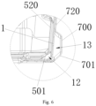
- FIG. 6 only shows the specific structure of the bottom of the right end supporting beam 520.
- the specific structure of the left end supporting beam 510 and the specific structure of the bottom of the right end supporting beam 520 have the same improvement design.
- each of the supporting beam transition segments 501 at the left and right ends and the liner 1 enclose a second cavity structure 12 to facilitate the transferring and dispersion of the collision force and further improve the overall use effect of the lower case.
- the outer reinforcement portion includes end anti-collision beams 7 fixedly connected to the two ends of the liner 1 respectively, side reinforcement beams 8 fixedly connected to the two sides of the liner 1 respectively, and a bottom protection plate 9 fixedly connected to the bottom of the liner 1, so as to form overall protection for the liner 1, thus effectively improving the overall strength and rigidity of the lower case.
- the two end anti-collision beams 7 include a left anti-collision beam 710 and a right anti-collision beam 720 to facilitate the descriptions of related contents in this embodiment.
- bulges 700 which protrude outwards are formed at bottom portions of the end anti-collision beams 7, so that a third cavity structure 13 is formed between each of the end anti-collision beams 7 and the liner 1, which can further transfer and disperse the collision force, and improve the overall anti-collision effect of the lower case.
- bottom ends of the end anti-collision beams 7 extend to the bottom of the liner 1; and bottom portions of the end anti-collision beams 7 are provided with anti-collision beam transition segments 701 which tilt towards the bottom of the liner 1 for transitioning.
- the collision force can be transferred to the bottom of the lower case; and the anti-collision beam transition segments cooperate with the supporting beam transition segments 501 to further reduce the risk that the lower case presses the modules due to the excessive internal deformation.
- the bottoms of the left end anti-collision beam 710 and the right end anti-collision beam 720 are respectively provided with the anti-collision beam transition segments 701 at the left and right ends.
- the anti-collision beam transition segment 701 at the left end corresponds to the bottom of the left end of the liner 1 and the supporting beam transition segment 501 at the left end
- the anti-collision beam transition segment 701 at the right end corresponds to the bottom of the right end of the liner 1 and the supporting beam transition segment 501 at the right end. It is convenient for the overall structural arrangement of the lower case, and the transition segments can cooperate with each other to improve the overall strength and rigidity of the bottom of the lower case.
- a liner flange 100 which is outwards turnup is formed at a top of the liner 1
- reinforcement beam flanges 800 are formed at tops of the side reinforcement beams 8 and are configured to be connected to the liner flange 100 in a superimposed manner, so that it is conductive to the assembling of the liner 1 and the side reinforcement beams 8.
- the battery pack lower case further includes mounting sleeves 10 configured to be fixedly connected to the liner flange 100 and the reinforcement beam flanges 800 which are connected in the superimposed manner.
- the mounting sleeves 10 are used to fixedly connect the liner flange 100 to the reinforcement beam flanges 800, so that the structure is simple and easy to realize, the cost is low, and repair and replacement are convenient.
- the mounting sleeves 10 here can be conventional bolt sleeves or screw sleeves.
- a fourth cavity structure 14 is encircled between each of the reinforcement beam flanges 800 and the liner flange 100 to further improve the transferring and dispersion of the collision force between the reinforcement beam flanges 800 and the liner flange 100, thus improving the overall use effect of the lower case.
- the battery pack lower case of this embodiment can effectively improve the overall strength and rigidity of the lower case by arranging the outer reinforcement portion fixedly connected to the liner 1 on the outer side of the liner 1.
- the risk that the lower case presses the module due to a structural failure can be reduced, thereby improving the safety of the battery pack.
- this embodiment also further relates to a battery pack which has the above-mentioned battery pack lower case.
- the battery pack of this embodiment adopting the above battery pack lower case can effectively improve the overall strength and rigidity of the lower case. In case of a vehicle collision, the risk that the lower case presses the module due to a structural failure can be reduced, thereby improving the safety of the battery pack.
Landscapes
- Chemical & Material Sciences (AREA)
- Chemical Kinetics & Catalysis (AREA)
- Electrochemistry (AREA)
- General Chemical & Material Sciences (AREA)
- Engineering & Computer Science (AREA)
- Aviation & Aerospace Engineering (AREA)
- Battery Mounting, Suspending (AREA)
- Arrangement Or Mounting Of Propulsion Units For Vehicles (AREA)
Abstract
Description
- The present disclosure claims priority to
China Patent Application No. 202120394672.0, filed on February 22, 2021 - The present disclosure relates to the technical field of batteries, in particular to a battery pack lower case. The present disclosure also relates to a battery pack with the above battery pack lower case.
- A power battery system is a core component of an electric vehicle, which is directly related to the usability, endurance, safe and reliable operation, and the like of a motor of the electric vehicle. A battery pack is an important component of a power system, which is used for storing a battery module of an electric vehicle.
- With the popularity of electric vehicles, people pay more attention to the safety of battery packs. In the prior art, the design of a battery pack case structure is more and more complex. Although the strength and rigidity of the battery pack case are improved to a certain extent, and the safety of a battery module is improved, the overall structural design of the battery pack case still has shortcomings. When a vehicle has a collision accident, there is also a risk that the battery pack case will severely press the battery module. A serious collision also easily causes the battery module to burn and explode.
- In view of this, the present disclosure aims to provide a battery pack lower case, so as to effectively improve the overall strength and rigidity of the lower case, thus improving the safety of a battery pack.
- In order to achieve the above objective, the technical solution of the present disclosure is achieved as follows.
- A battery pack lower case includes a liner provided with an accommodation cavity, wherein a lower-layer module mounting portion is arranged at a bottom of the accommodation cavity; an upper-layer module mounting portion is arranged on a side portion of the accommodation cavity; the upper-layer module mounting portion and the lower-layer module mounting portion are arranged one above the other in a spaced manner and are fixedly connected to the liner respectively; and an outer reinforcement portion fixedly connected to the liner is arranged at an outer side of the liner.
- Further, the lower-layer module mounting portion includes a middle mounting beam located in a middle portion, and side mounting beams separately arranged on two sides.
- Further, the upper-layer module mounting portion includes side supporting beams separately arranged on two sides of the accommodation cavity, and end supporting beams separately arranged at two ends of the accommodation cavity.
- Further, mounting platforms protruding into the accommodation cavity are arranged on the side supporting beams and the end supporting beams.
- Further, a first cavity structure is formed between each of the mounting platforms and the liner.
- Further, L-shaped reinforcement plates are fixedly connected between adjacent ones of the mounting platforms.
- Further, bottom ends of the end supporting beams extend to the bottom of the accommodation cavity; and bottoms of the end supporting beams are provided with supporting beam transition segments which tilt towards the bottom of the accommodation cavity for transitioning.
- Further, a second cavity structure is encircled between each of the supporting beam transition segments and the liner.
- Further, the outer reinforcement portion includes end anti-collision beams fixedly connected to the two ends of the liner respectively, side reinforcement beams fixedly connected to the two sides of the liner respectively, and a bottom protection plate fixedly connected to the bottom of the liner.
- Further, bulges which protrude outwards are formed at bottom portions of the end anti-collision beams, so that a third cavity structure is formed between each of the end anti-collision beams and the liner.
- Further, bottom ends of the end anti-collision beams (extend to the bottom of the liner; and bottom portions of the end anti-collision beams are provided with anti-collision beam transition segments which tilt towards the bottom of the liner for transitioning.
- Further, a liner flange which is outwards turnup is formed at a top of the liner; reinforcement beam flanges are formed at tops of the side reinforcement beams and are configured to be connected to the liner flange in a superimposed manner.
- Further, a fourth cavity structure is encircled between each of the reinforcement beam flanges and the liner flange.
- Further, the battery pack lower case further includes mounting sleeves configured to be fixedly connected to the liner flange and the reinforcement beam flanges which are connected in the superimposed manner.
- Compared with the prior art, the present disclosure has the following advantages:
- (1) The battery pack lower case of the present disclosure can effectively improve the overall strength and rigidity of the lower case by arranging the outer reinforcement portion fixedly connected to the liner on the outer side of the liner. When a vehicle has a collision accident, the risk that the lower case presses the module due to a structural failure can be reduced, thereby improving the safety of the battery pack.
- (2) The lower-layer module mounting portion is mainly composed of the middle mounting beam and the side mounting beams on both sides, and can cooperate with the outer reinforcement portion to further improve the overall strength and rigidity of the lower case.
- (3) The upper-layer module mounting portion is mainly composed of side supporting beams on both sides and the end supporting beams at both ends. In addition to facilitating the installation of upper-layer modules, the upper-layer module mounting portion can also cooperate with the outer reinforcement portion to further improve the overall strength and rigidity of the lower case.
- (4) The mounting platforms are arranged on the side supporting beams and the end supporting beams to facilitate the installation and removal of the upper-layer modules on the upper-layer module mounting portion. Meanwhile, the mounting platforms can also be configured to optimize the overall structure of the side supporting beams and the end supporting beams, and improve the overall strength and rigidity of the side supporting beams and the end supporting beams.
- (5) The reinforcement plates are fixedly connected between adjacent ones of the mounting platforms, which can effectively improve the connection strength and rigidity between the various mounting platforms, and indirectly improve the overall strength and rigidity of the lower case, thus further reducing the risk that the lower case presses the modules due to an excessive internal deformation in a collision. Moreover, the reinforcement plates are L-shaped, with a reasonable structure, which is convenient for the overall arrangement of the inside of the lower case.
- (6) The bottoms of the end supporting beams are provided with the supporting beam transition segments which tilt towards the bottom of the accommodation cavity for transitioning. When a vehicle has a collision accident, a collision force can be transferred to the bottom of the lower case, thus reducing the risk of a structural strength failure of the lower case caused by excessive dispersed local stress, that is, reducing the risk that the lower case presses the modules due to the excessive internal deformation.
- (7) The outer reinforcement portion is mainly composed of the end anti-collision beams at both ends, the side reinforcement beams on both sides and the bottom protection plate, which can form an overall protection for the liner, thus effectively improving the overall strength and rigidity of the lower case.
- (8) The bulges which protrude outwards are formed at the bottom portions of the end anti-collision beams, so that the cavity structure is formed between each of the end anti-collision beams and the liner, which can transfer and disperse the collision force, and improve the overall anti-collision effect of the lower case.
- (9) The bottom portions of the end anti-collision beams are provided with the anti-collision beam transition segments which tilt towards the bottom of the liner for transitioning. When a vehicle has a collision accident, the collision force can be transferred to the bottom of the lower case; and the anti-collision beam transition segments cooperate with the supporting beam transition segments to further reduce the risk that the lower case presses the modules due to the excessive internal deformation.
- (10) The liner flange is formed at the top of the liner, and the reinforcement beam flanges are formed at tops of the side reinforcement beams and are configured to be connected to the liner flange in the superimposed manner, which is conducive to the assembling of the liner and the side reinforcement beams. At the same time, the mounting sleeves are used to achieve the fixed connection between the liner flange and the reinforcement beam flanges, so that the structure is simple and easy to realize, the cost is low, and repair and replacement are convenient.
- Another objective of the present disclosure is to provide a battery pack, which has the above battery pack lower case.
- Compared with the prior art, the battery pack of the present disclosure has the same beneficial effect as the battery pack lower case, and will not be described here.
- The drawings forming one part of the present disclosure are used to provide a further understanding of the present disclosure. The schematic embodiments of the present disclosure and the descriptions of the embodiments are used to explain the present disclosure, and do not constitute an improper limitation of the present disclosure. In the drawings:
-
Fig. 1 is an exploded diagram of a battery pack lower case according to an embodiment of the present disclosure; -
Fig. 2 is a top view of a battery pack lower case according to an embodiment of the present disclosure; -
Fig. 3 is a schematic sectional view of A-A inFig. 2 ; -
Fig. 4 is a partially enlarged diagram of the part C inFig. 3 ; -
Fig. 5 is a schematic sectional view of B-B inFig. 2 ; and -
Fig. 6 is a partially enlarged diagram of the part D inFig. 5 . - Numerals in the drawings:
- 1: liner; 100: liner flange; 2: middle mounting beam; 3: side mounting beam; 4: side supporting beam; 5: end supporting beam; 500: mounting platform; 501: supporting beam transition segment; 510: left end supporting beam; 520: right end supporting beam;
- 6: reinforcement plate; 7: end anti-collision beam; 700: bulge; 701: anti-collision beam transition segment; 710: left end anti-collision beam; 720: right end anti-collision beam;
- 8: side reinforcement beam; 800: reinforcement beam flange; 9: bottom protection plate; 10: mounting sleeve; 11: first cavity structure; 12: second cavity structure; 13: third cavity structure; and 14: fourth cavity structure.
- It should be noted that the embodiments in the present disclosure and features in the embodiments may be combined with each other without conflicts.
- In the description of the present disclosure, it should be noted that orientations or positional relationships indicated by the terms "upper", "lower", "inside", "outside" and the like are orientations or positional relationships as shown in the drawings, and are only for the purpose of facilitating and simplifying the description of the present disclosure instead of indicating or implying that devices or elements indicated must have particular orientations, and be constructed and operated in the particular orientations, so that these terms are construed as limiting the present disclosure. In addition, the terms "first", "second" and the like are only for the purpose of description, and may not be understood as indicating or implying the relative importance.
- In addition, in the descriptions of the present disclosure, unless otherwise clearly defined, the terms "mount", "connect", "connected" and "connector" should be broadly understood. For example, it may be fixed connection, detachable connection, integral connection, mechanical connection, electrical connection, direct connection, indirect connection via an intermediate, or inter-connection between two elements. Those of ordinary skill in the art can understand the specific meanings of the above terms in the present disclosure in combination with specific situations.
- The present disclosure will be described in detail below with reference to the accompanying drawings and in combination with embodiments.
- This embodiment relates to a battery pack lower case. As for an overall structure, the battery pack lower case includes a
liner 1 provided with an accommodation cavity; a lower-layer module mounting portion is arranged at a bottom of the accommodation cavity; an upper-layer module mounting portion is arranged on a side portion of the accommodation cavity; the upper-layer module mounting portion and the lower-layer module mounting portion are arranged one above the other in a spaced manner and are fixedly connected to theliner 1 respectively; and an outer reinforcement portion fixedly connected to theliner 1 is arranged at an outer side of theliner 1, so as to effectively improve the overall strength and rigidity of the lower case and improve the safety of the battery pack. - It is worth mentioning here that all structures of the battery pack lower case are not described in this embodiment, and can all refer to the ordinary structural parts in the prior art, so descriptions thereof are omitted here.
- Based on the above design idea, an exemplary structure of the battery pack lower case of this embodiment is as shown in
Fig. 1 to Fig. 6 . As mentioned above, the battery pack lower case in this embodiment includes theliner 1 provided with the accommodation cavity. The lower-layer module mounting portion is arranged at the bottom of the accommodation cavity. The upper-layer module mounting portion is arranged on the side portion of the accommodation cavity. The upper-layer module mounting portion and the lower-layer module mounting portion are arranged one above the other in a spaced manner and are fixedly connected to theliner 1 respectively. The outer reinforcement portion fixedly connected to theliner 1 is arranged at the outer side of theliner 1. - As a preferable implementation, as shown in
Fig. 2 , the above lower-layer module mounting portion includes amiddle mounting beam 2 located in a middle portion, andside mounting beams 3 separately arranged on two sides, and can cooperate with the outer reinforcement portion to further improve the overall strength and rigidity of the lower case. In addition, in order to facilitate the fixing of upper-layer modules, the upper-layer module mounting portion in this embodiment includesside supporting beams 4 separately arranged on two sides of the accommodation cavity, and end supportingbeams 5 separately arranged at two ends of the accommodation cavity. Furthermore, in order to facilitate the description, in the state shown inFig. 3 , the twoend supporting beams 5 include a leftend supporting beam 510 and the rightend supporting beam 520. In addition to facilitating the fixing of lower-layer modules, the upper-layer module mounting portion can also cooperate with the outer reinforcement portion to further improve the overall strength and rigidity of the lower case. - Referring to
Fig. 3 to Fig. 5 , mountingplatforms 500 protruding into the accommodation cavity are arranged on the variousside supporting beams 4 and the variousend supporting beams 5, so as to facilitate the installation and removal of the upper-layer modules on the upper-layer module mounting portion. Meanwhile, the mountingplatforms 500 can also be configured to optimize the overall structure of theside supporting beams 4 and theend supporting beams 5, and improve the overall strength and rigidity of theside supporting beams 4 and the end supporting beams 5. It is worth mentioning that the mountingplatforms 500 can be preferably configured to form afirst cavity structure 11 together with theliner 1, so that the collision force can be transferred and dispersed, thus achieving the above optimization of the overall structure of theside supporting beams 4 and theend supporting beams 5 to further improve the overall strength and rigidity of the lower case. - Meanwhile, in a further setting, as shown in
Fig. 2 , in this embodiment, L-shapedreinforcement plates 6 are fixedly connected between adjacent ones of the mountingplatforms 500, which can effectively improve the connection strength and rigidity between the various mountingplatforms 500, and indirectly improve the overall strength and rigidity of the lower case, thus further reducing the risk that the lower case presses the modules due to an excessive internal deformation in a collision. Moreover, thereinforcement plates 6 are L-shaped, with a reasonable structure, which is convenient for the overall arrangement of the inside of the lower case. In a specific structure, thereinforcement plates 6 and the various mountingplatforms 500 can be fixedly connected by bolts, so that the structure is simple and convenient to realize; the cost is low; and repair and replacement are convenient. - In addition, in order to improve the use effect of the two
end supporting beams 5, as shown inFig. 5 andFig. 6 , bottom ends of the twoend supporting beams 5 extend to the bottom of the accommodation cavity; and bottoms of the twoend supporting beams 5 are provided with supportingbeam transition segments 501 which tilt towards the bottom of the accommodation cavity for transitioning. When a vehicle has a collision accident, a collision force can be transferred to the bottom of the lower case, thus reducing the risk of a structural strength failure of the lower case caused by excessive dispersed local stress, that is, reducing the risk that the lower case presses the modules due to the excessive internal deformation. - Of course, in the above content,
Fig. 6 only shows the specific structure of the bottom of the rightend supporting beam 520. The specific structure of the leftend supporting beam 510 and the specific structure of the bottom of the rightend supporting beam 520 have the same improvement design. In the states shown inFig. 5 andFig. 6 , each of the supportingbeam transition segments 501 at the left and right ends and theliner 1 enclose asecond cavity structure 12 to facilitate the transferring and dispersion of the collision force and further improve the overall use effect of the lower case. - In this embodiment, as shown in
Fig. 2 ,Fig. 5 andFig. 6 , the outer reinforcement portion includesend anti-collision beams 7 fixedly connected to the two ends of theliner 1 respectively, side reinforcement beams 8 fixedly connected to the two sides of theliner 1 respectively, and abottom protection plate 9 fixedly connected to the bottom of theliner 1, so as to form overall protection for theliner 1, thus effectively improving the overall strength and rigidity of the lower case. Specifically, in the state shown inFig. 5 , the twoend anti-collision beams 7 include a left anti-collision beam 710 and aright anti-collision beam 720 to facilitate the descriptions of related contents in this embodiment. Preferably, bulges 700 which protrude outwards are formed at bottom portions of the end anti-collision beams 7, so that athird cavity structure 13 is formed between each of theend anti-collision beams 7 and theliner 1, which can further transfer and disperse the collision force, and improve the overall anti-collision effect of the lower case. - Preferably, in this embodiment, as shown in
Fig. 5 andFig. 6 , bottom ends of theend anti-collision beams 7 extend to the bottom of theliner 1; and bottom portions of theend anti-collision beams 7 are provided with anti-collisionbeam transition segments 701 which tilt towards the bottom of theliner 1 for transitioning. When a vehicle has a collision accident, the collision force can be transferred to the bottom of the lower case; and the anti-collision beam transition segments cooperate with the supportingbeam transition segments 501 to further reduce the risk that the lower case presses the modules due to the excessive internal deformation. In order to facilitate the description, in the state shown inFig. 5 , the bottoms of the left end anti-collision beam 710 and the rightend anti-collision beam 720 are respectively provided with the anti-collisionbeam transition segments 701 at the left and right ends. The anti-collisionbeam transition segment 701 at the left end corresponds to the bottom of the left end of theliner 1 and the supportingbeam transition segment 501 at the left end, and the anti-collisionbeam transition segment 701 at the right end corresponds to the bottom of the right end of theliner 1 and the supportingbeam transition segment 501 at the right end. It is convenient for the overall structural arrangement of the lower case, and the transition segments can cooperate with each other to improve the overall strength and rigidity of the bottom of the lower case. - In addition, in the states as shown in
Fig. 1 ,Fig. 2 ,Fig. 3 andFig. 5 , aliner flange 100 which is outwards turnup is formed at a top of theliner 1, andreinforcement beam flanges 800 are formed at tops of the side reinforcement beams 8 and are configured to be connected to theliner flange 100 in a superimposed manner, so that it is conductive to the assembling of theliner 1 and the side reinforcement beams 8. Furthermore, the battery pack lower case further includes mountingsleeves 10 configured to be fixedly connected to theliner flange 100 and thereinforcement beam flanges 800 which are connected in the superimposed manner. The mountingsleeves 10 are used to fixedly connect theliner flange 100 to thereinforcement beam flanges 800, so that the structure is simple and easy to realize, the cost is low, and repair and replacement are convenient. The mountingsleeves 10 here can be conventional bolt sleeves or screw sleeves. In addition, in practical applications, afourth cavity structure 14 is encircled between each of thereinforcement beam flanges 800 and theliner flange 100 to further improve the transferring and dispersion of the collision force between thereinforcement beam flanges 800 and theliner flange 100, thus improving the overall use effect of the lower case. - The battery pack lower case of this embodiment can effectively improve the overall strength and rigidity of the lower case by arranging the outer reinforcement portion fixedly connected to the
liner 1 on the outer side of theliner 1. When a vehicle has a collision accident, the risk that the lower case presses the module due to a structural failure can be reduced, thereby improving the safety of the battery pack. - Finally, this embodiment also further relates to a battery pack which has the above-mentioned battery pack lower case.
- The battery pack of this embodiment adopting the above battery pack lower case can effectively improve the overall strength and rigidity of the lower case. In case of a vehicle collision, the risk that the lower case presses the module due to a structural failure can be reduced, thereby improving the safety of the battery pack.
- The above descriptions are only optional embodiments of the present disclosure and are not intended to limit the present disclosure. Any modification, equivalent replacement, improvement, etc. made within the spirit and principle of the present disclosure shall all fall within the protection scope of the present disclosure.
Claims (15)
- A battery pack lower case, comprising a liner (1) provided with an accommodation cavity, wherein a lower-layer module mounting portion is arranged at a bottom of the accommodation cavity; an upper-layer module mounting portion is arranged on a side portion of the accommodation cavity; the upper-layer module mounting portion and the lower-layer module mounting portion are arranged one above the other in a spaced manner and are fixedly connected to the liner (1) respectively; and an outer reinforcement portion fixedly connected to the liner (1) is arranged at an outer side of the liner (1).
- The battery pack lower case according to claim 1, wherein the lower-layer module mounting portion comprises a middle mounting beam (2) located in a middle portion, and side mounting beams (3) separately arranged on two sides.
- The battery pack lower case according to claim 1, wherein the upper-layer module mounting portion comprises side supporting beams (4) separately arranged on two sides of the accommodation cavity, and end supporting beams (5) separately arranged at two ends of the accommodation cavity.
- The battery pack lower case according to claim 3, wherein mounting platforms (500) protruding into the accommodation cavity are arranged on the side supporting beams (4) and the end supporting beams (5).
- The battery pack lower case according to claim 4, wherein L-shaped reinforcement plates (6) are fixedly connected between adjacent ones of the mounting platforms (500).
- The battery pack lower case according to claim 4, wherein a first cavity structure (11) is formed between each of the mounting platforms (500) and the liner (1).
- The battery pack lower case according to claim 3, wherein bottom ends of the end supporting beams (5) extend to the bottom of the accommodation cavity; and bottoms of the end supporting beams (5) are provided with supporting beam transition segments (501) which tilt towards the bottom of the accommodation cavity for transitioning.
- The battery pack lower case according to claim 7, wherein a second cavity structure (12) is encircled between each of the supporting beam transition segments (501) and the liner (1).
- The battery pack lower case according to any one of claims 1 to 8, wherein the outer reinforcement portion comprises end anti-collision beams (7) fixedly connected to the two ends of the liner (1) respectively, side reinforcement beams (8) fixedly connected to the two sides of the liner (1) respectively, and a bottom protection plate (9) fixedly connected to the bottom of the liner (1).
- The battery pack lower case according to claim 9, wherein bulges (700) which protrude outwards are formed at bottom portions of the end anti-collision beams (7), so that a third cavity structure (13) is formed between each of the end anti-collision beams (7) and the liner (1).
- The battery pack lower case according to claim 9, wherein bottom ends of the end anti-collision beams (7) extend to the bottom of the liner (1); and bottom portions of the end anti-collision beams (7) are provided with anti-collision beam transition segments (701) which tilt towards the bottom of the liner (1) for transitioning.
- The battery pack lower case according to claim 9, wherein a liner flange (100) which is outwards turnup is formed at a top of the liner (1); reinforcement beam flanges (800) are formed at tops of the side reinforcement beams (8) and are configured to be connected to the liner flange (100) in a superimposed manner.
- The battery pack lower case according to claim 12, wherein a fourth cavity structure (14) is encircled between each of the reinforcement beam flanges (800) and the liner flange (100).
- The battery pack lower case according to claim 12, wherein the battery pack lower case further comprises mounting sleeves (10) configured to be fixedly connected to the liner flange (100) and the reinforcement beam flanges (800) which are connected in the superimposed manner.
- A battery pack, comprising the battery pack lower case according to any one of claims 1 to 14.
Applications Claiming Priority (2)
| Application Number | Priority Date | Filing Date | Title |
|---|---|---|---|
| CN202120394672.0U CN214254601U (en) | 2021-02-22 | 2021-02-22 | Battery pack lower casing |
| PCT/CN2022/077119 WO2022174832A1 (en) | 2021-02-22 | 2022-02-21 | Battery pack lower case and battery pack |
Publications (2)
| Publication Number | Publication Date |
|---|---|
| EP4164032A1 true EP4164032A1 (en) | 2023-04-12 |
| EP4164032A4 EP4164032A4 (en) | 2024-10-09 |
Family
ID=77728386
Family Applications (1)
| Application Number | Title | Priority Date | Filing Date |
|---|---|---|---|
| EP22755605.7A Pending EP4164032A4 (en) | 2021-02-22 | 2022-02-21 | BATTERY PACK BASE AND BATTERY PACK |
Country Status (3)
| Country | Link |
|---|---|
| EP (1) | EP4164032A4 (en) |
| CN (1) | CN214254601U (en) |
| WO (1) | WO2022174832A1 (en) |
Families Citing this family (2)
| Publication number | Priority date | Publication date | Assignee | Title |
|---|---|---|---|---|
| CN214254601U (en) * | 2021-02-22 | 2021-09-21 | 蜂巢能源科技有限公司 | Battery pack lower casing |
| CN115939648B (en) * | 2022-12-26 | 2025-10-24 | 首钢集团有限公司 | A power battery casing and a method for preparing the same |
Family Cites Families (10)
| Publication number | Priority date | Publication date | Assignee | Title |
|---|---|---|---|---|
| DE102008059680B4 (en) * | 2008-11-29 | 2018-04-05 | GM Global Technology Operations LLC (n. d. Ges. d. Staates Delaware) | Device for holding a battery |
| CN206441797U (en) * | 2017-02-14 | 2017-08-25 | 重庆长安汽车股份有限公司 | A kind of automobile housing of power cell |
| WO2019060838A2 (en) * | 2017-09-25 | 2019-03-28 | Milwaukee Electric Tool Corporation | Battery pack with lanyard receiver and tether with quick attachment |
| CN207320203U (en) * | 2017-10-19 | 2018-05-04 | 长城汽车股份有限公司 | Battery pack and there is its vehicle |
| CN109560218B (en) * | 2017-10-19 | 2022-09-20 | 蜂巢能源科技有限公司 | Lower shell for battery pack and battery pack |
| JP7198422B2 (en) * | 2018-01-16 | 2023-01-04 | スズキ株式会社 | Body structure of electric vehicle |
| JP6724061B2 (en) * | 2018-04-18 | 2020-07-15 | 本田技研工業株式会社 | Battery pack |
| CN108878703A (en) * | 2018-06-06 | 2018-11-23 | 奇瑞汽车股份有限公司 | A kind of battery pack structure of new-energy automobile |
| WO2020193426A1 (en) * | 2019-03-22 | 2020-10-01 | Voestalpine Metal Forming Gmbh | Battery case, traction battery having said battery case and vehicle having said traction battery |
| CN214254601U (en) * | 2021-02-22 | 2021-09-21 | 蜂巢能源科技有限公司 | Battery pack lower casing |
-
2021
- 2021-02-22 CN CN202120394672.0U patent/CN214254601U/en active Active
-
2022
- 2022-02-21 WO PCT/CN2022/077119 patent/WO2022174832A1/en not_active Ceased
- 2022-02-21 EP EP22755605.7A patent/EP4164032A4/en active Pending
Also Published As
| Publication number | Publication date |
|---|---|
| CN214254601U (en) | 2021-09-21 |
| EP4164032A4 (en) | 2024-10-09 |
| WO2022174832A1 (en) | 2022-08-25 |
Similar Documents
| Publication | Publication Date | Title |
|---|---|---|
| CN219007568U (en) | Battery pack quick change guide device and battery change vehicle including same | |
| US8501344B2 (en) | Battery module of compact joint structure | |
| WO2021083062A1 (en) | Battery pack lower box body, battery pack, device, and assembling method for battery pack lower box body | |
| CN218385558U (en) | Battery module and battery package | |
| US20220134855A1 (en) | Electric driveline and electric vehicle using the electric driveline | |
| EP4471953B1 (en) | Battery box and electric equipment | |
| US20260124896A1 (en) | Battery installation frame, frame assembly, and vehicle | |
| CN116417739A (en) | Battery tray, battery pack and vehicle | |
| WO2022174832A1 (en) | Battery pack lower case and battery pack | |
| CN117374494A (en) | Side beam for battery tray, power battery pack and vehicle | |
| CN118907232B (en) | Integrated new energy frame and new energy truck | |
| KR20220111667A (en) | Protection assembly and battery housing comprising the same | |
| CN222365659U (en) | Box, battery and electrical device | |
| EP4604292A1 (en) | Battery and electric apparatus | |
| JP2024120972A (en) | Power storage device and battery pack | |
| WO2024152376A1 (en) | Battery and vehicle | |
| CN216636293U (en) | Pure electric cement mixer truck and chassis thereof | |
| CN221486742U (en) | Battery pack and power device | |
| CN115764101A (en) | Chassis and cars | |
| CN222168598U (en) | Battery device, box and electric equipment | |
| CN219457879U (en) | Module end plate, battery module and electronic equipment | |
| CN219619224U (en) | Vehicle and vehicle body thereof | |
| CN219312859U (en) | Frame and vehicle | |
| CN221427924U (en) | BMS combined support | |
| CN223487205U (en) | Battery device, battery box and electric equipment |
Legal Events
| Date | Code | Title | Description |
|---|---|---|---|
| STAA | Information on the status of an ep patent application or granted ep patent |
Free format text: STATUS: THE INTERNATIONAL PUBLICATION HAS BEEN MADE |
|
| PUAI | Public reference made under article 153(3) epc to a published international application that has entered the european phase |
Free format text: ORIGINAL CODE: 0009012 |
|
| STAA | Information on the status of an ep patent application or granted ep patent |
Free format text: STATUS: REQUEST FOR EXAMINATION WAS MADE |
|
| 17P | Request for examination filed |
Effective date: 20230109 |
|
| AK | Designated contracting states |
Kind code of ref document: A1 Designated state(s): AL AT BE BG CH CY CZ DE DK EE ES FI FR GB GR HR HU IE IS IT LI LT LU LV MC MK MT NL NO PL PT RO RS SE SI SK SM TR |
|
| RAP3 | Party data changed (applicant data changed or rights of an application transferred) |
Owner name: SVOLT ENERGY TECHNOLOGY CO., LTD. |
|
| DAV | Request for validation of the european patent (deleted) | ||
| DAX | Request for extension of the european patent (deleted) | ||
| A4 | Supplementary search report drawn up and despatched |
Effective date: 20240909 |
|
| RIC1 | Information provided on ipc code assigned before grant |
Ipc: H01M 50/249 20210101ALI20240903BHEP Ipc: H01M 50/244 20210101ALI20240903BHEP Ipc: H01M 50/242 20210101ALI20240903BHEP Ipc: H01M 50/204 20210101ALI20240903BHEP Ipc: H01M 50/102 20210101AFI20240903BHEP |
|
| GRAP | Despatch of communication of intention to grant a patent |
Free format text: ORIGINAL CODE: EPIDOSNIGR1 |
|
| STAA | Information on the status of an ep patent application or granted ep patent |
Free format text: STATUS: GRANT OF PATENT IS INTENDED |
|
| INTG | Intention to grant announced |
Effective date: 20260227 |