EP4164025A1 - Battery pack, electronic device, and vehicle - Google Patents
Battery pack, electronic device, and vehicle Download PDFInfo
- Publication number
- EP4164025A1 EP4164025A1 EP21883010.7A EP21883010A EP4164025A1 EP 4164025 A1 EP4164025 A1 EP 4164025A1 EP 21883010 A EP21883010 A EP 21883010A EP 4164025 A1 EP4164025 A1 EP 4164025A1
- Authority
- EP
- European Patent Office
- Prior art keywords
- battery pack
- sensing wire
- fixing portion
- bending part
- present disclosure
- Prior art date
- Legal status (The legal status is an assumption and is not a legal conclusion. Google has not performed a legal analysis and makes no representation as to the accuracy of the status listed.)
- Pending
Links
Images



Classifications
-
- H—ELECTRICITY
- H01—ELECTRIC ELEMENTS
- H01M—PROCESSES OR MEANS, e.g. BATTERIES, FOR THE DIRECT CONVERSION OF CHEMICAL ENERGY INTO ELECTRICAL ENERGY
- H01M10/00—Secondary cells; Manufacture thereof
- H01M10/42—Methods or arrangements for servicing or maintenance of secondary cells or secondary half-cells
- H01M10/48—Accumulators combined with arrangements for measuring, testing or indicating the condition of cells, e.g. the level or density of the electrolyte
- H01M10/482—Accumulators combined with arrangements for measuring, testing or indicating the condition of cells, e.g. the level or density of the electrolyte for several batteries or cells simultaneously or sequentially
-
- H—ELECTRICITY
- H01—ELECTRIC ELEMENTS
- H01M—PROCESSES OR MEANS, e.g. BATTERIES, FOR THE DIRECT CONVERSION OF CHEMICAL ENERGY INTO ELECTRICAL ENERGY
- H01M10/00—Secondary cells; Manufacture thereof
- H01M10/42—Methods or arrangements for servicing or maintenance of secondary cells or secondary half-cells
-
- H—ELECTRICITY
- H01—ELECTRIC ELEMENTS
- H01M—PROCESSES OR MEANS, e.g. BATTERIES, FOR THE DIRECT CONVERSION OF CHEMICAL ENERGY INTO ELECTRICAL ENERGY
- H01M10/00—Secondary cells; Manufacture thereof
- H01M10/42—Methods or arrangements for servicing or maintenance of secondary cells or secondary half-cells
- H01M10/48—Accumulators combined with arrangements for measuring, testing or indicating the condition of cells, e.g. the level or density of the electrolyte
-
- H—ELECTRICITY
- H01—ELECTRIC ELEMENTS
- H01M—PROCESSES OR MEANS, e.g. BATTERIES, FOR THE DIRECT CONVERSION OF CHEMICAL ENERGY INTO ELECTRICAL ENERGY
- H01M10/00—Secondary cells; Manufacture thereof
- H01M10/42—Methods or arrangements for servicing or maintenance of secondary cells or secondary half-cells
- H01M10/48—Accumulators combined with arrangements for measuring, testing or indicating the condition of cells, e.g. the level or density of the electrolyte
- H01M10/486—Accumulators combined with arrangements for measuring, testing or indicating the condition of cells, e.g. the level or density of the electrolyte for measuring temperature
-
- H—ELECTRICITY
- H01—ELECTRIC ELEMENTS
- H01M—PROCESSES OR MEANS, e.g. BATTERIES, FOR THE DIRECT CONVERSION OF CHEMICAL ENERGY INTO ELECTRICAL ENERGY
- H01M50/00—Constructional details or processes of manufacture of the non-active parts of electrochemical cells other than fuel cells, e.g. hybrid cells
- H01M50/20—Mountings; Secondary casings or frames; Racks, modules or packs; Suspension devices; Shock absorbers; Transport or carrying devices; Holders
-
- H—ELECTRICITY
- H01—ELECTRIC ELEMENTS
- H01M—PROCESSES OR MEANS, e.g. BATTERIES, FOR THE DIRECT CONVERSION OF CHEMICAL ENERGY INTO ELECTRICAL ENERGY
- H01M50/00—Constructional details or processes of manufacture of the non-active parts of electrochemical cells other than fuel cells, e.g. hybrid cells
- H01M50/20—Mountings; Secondary casings or frames; Racks, modules or packs; Suspension devices; Shock absorbers; Transport or carrying devices; Holders
- H01M50/204—Racks, modules or packs for multiple batteries or multiple cells
- H01M50/207—Racks, modules or packs for multiple batteries or multiple cells characterised by their shape
- H01M50/209—Racks, modules or packs for multiple batteries or multiple cells characterised by their shape adapted for prismatic or rectangular cells
-
- H—ELECTRICITY
- H01—ELECTRIC ELEMENTS
- H01M—PROCESSES OR MEANS, e.g. BATTERIES, FOR THE DIRECT CONVERSION OF CHEMICAL ENERGY INTO ELECTRICAL ENERGY
- H01M50/00—Constructional details or processes of manufacture of the non-active parts of electrochemical cells other than fuel cells, e.g. hybrid cells
- H01M50/20—Mountings; Secondary casings or frames; Racks, modules or packs; Suspension devices; Shock absorbers; Transport or carrying devices; Holders
- H01M50/204—Racks, modules or packs for multiple batteries or multiple cells
- H01M50/207—Racks, modules or packs for multiple batteries or multiple cells characterised by their shape
- H01M50/211—Racks, modules or packs for multiple batteries or multiple cells characterised by their shape adapted for pouch cells
-
- H—ELECTRICITY
- H01—ELECTRIC ELEMENTS
- H01M—PROCESSES OR MEANS, e.g. BATTERIES, FOR THE DIRECT CONVERSION OF CHEMICAL ENERGY INTO ELECTRICAL ENERGY
- H01M50/00—Constructional details or processes of manufacture of the non-active parts of electrochemical cells other than fuel cells, e.g. hybrid cells
- H01M50/20—Mountings; Secondary casings or frames; Racks, modules or packs; Suspension devices; Shock absorbers; Transport or carrying devices; Holders
- H01M50/204—Racks, modules or packs for multiple batteries or multiple cells
- H01M50/207—Racks, modules or packs for multiple batteries or multiple cells characterised by their shape
- H01M50/213—Racks, modules or packs for multiple batteries or multiple cells characterised by their shape adapted for cells having curved cross-section, e.g. round or elliptic
-
- H—ELECTRICITY
- H01—ELECTRIC ELEMENTS
- H01M—PROCESSES OR MEANS, e.g. BATTERIES, FOR THE DIRECT CONVERSION OF CHEMICAL ENERGY INTO ELECTRICAL ENERGY
- H01M50/00—Constructional details or processes of manufacture of the non-active parts of electrochemical cells other than fuel cells, e.g. hybrid cells
- H01M50/20—Mountings; Secondary casings or frames; Racks, modules or packs; Suspension devices; Shock absorbers; Transport or carrying devices; Holders
- H01M50/249—Mountings; Secondary casings or frames; Racks, modules or packs; Suspension devices; Shock absorbers; Transport or carrying devices; Holders specially adapted for aircraft or vehicles, e.g. cars or trains
-
- H—ELECTRICITY
- H01—ELECTRIC ELEMENTS
- H01M—PROCESSES OR MEANS, e.g. BATTERIES, FOR THE DIRECT CONVERSION OF CHEMICAL ENERGY INTO ELECTRICAL ENERGY
- H01M50/00—Constructional details or processes of manufacture of the non-active parts of electrochemical cells other than fuel cells, e.g. hybrid cells
- H01M50/20—Mountings; Secondary casings or frames; Racks, modules or packs; Suspension devices; Shock absorbers; Transport or carrying devices; Holders
- H01M50/262—Mountings; Secondary casings or frames; Racks, modules or packs; Suspension devices; Shock absorbers; Transport or carrying devices; Holders with fastening means, e.g. locks
-
- H—ELECTRICITY
- H01—ELECTRIC ELEMENTS
- H01M—PROCESSES OR MEANS, e.g. BATTERIES, FOR THE DIRECT CONVERSION OF CHEMICAL ENERGY INTO ELECTRICAL ENERGY
- H01M50/00—Constructional details or processes of manufacture of the non-active parts of electrochemical cells other than fuel cells, e.g. hybrid cells
- H01M50/20—Mountings; Secondary casings or frames; Racks, modules or packs; Suspension devices; Shock absorbers; Transport or carrying devices; Holders
- H01M50/298—Mountings; Secondary casings or frames; Racks, modules or packs; Suspension devices; Shock absorbers; Transport or carrying devices; Holders characterised by the wiring of battery packs
-
- H—ELECTRICITY
- H01—ELECTRIC ELEMENTS
- H01M—PROCESSES OR MEANS, e.g. BATTERIES, FOR THE DIRECT CONVERSION OF CHEMICAL ENERGY INTO ELECTRICAL ENERGY
- H01M50/00—Constructional details or processes of manufacture of the non-active parts of electrochemical cells other than fuel cells, e.g. hybrid cells
- H01M50/50—Current conducting connections for cells or batteries
- H01M50/569—Constructional details of current conducting connections for detecting conditions inside cells or batteries, e.g. details of voltage sensing terminals
-
- H—ELECTRICITY
- H01—ELECTRIC ELEMENTS
- H01M—PROCESSES OR MEANS, e.g. BATTERIES, FOR THE DIRECT CONVERSION OF CHEMICAL ENERGY INTO ELECTRICAL ENERGY
- H01M2220/00—Batteries for particular applications
- H01M2220/20—Batteries in motive systems, e.g. vehicle, ship, plane
-
- H—ELECTRICITY
- H01—ELECTRIC ELEMENTS
- H01M—PROCESSES OR MEANS, e.g. BATTERIES, FOR THE DIRECT CONVERSION OF CHEMICAL ENERGY INTO ELECTRICAL ENERGY
- H01M2220/00—Batteries for particular applications
- H01M2220/30—Batteries in portable systems, e.g. mobile phone, laptop
-
- Y—GENERAL TAGGING OF NEW TECHNOLOGICAL DEVELOPMENTS; GENERAL TAGGING OF CROSS-SECTIONAL TECHNOLOGIES SPANNING OVER SEVERAL SECTIONS OF THE IPC; TECHNICAL SUBJECTS COVERED BY FORMER USPC CROSS-REFERENCE ART COLLECTIONS [XRACs] AND DIGESTS
- Y02—TECHNOLOGIES OR APPLICATIONS FOR MITIGATION OR ADAPTATION AGAINST CLIMATE CHANGE
- Y02E—REDUCTION OF GREENHOUSE GAS [GHG] EMISSIONS, RELATED TO ENERGY GENERATION, TRANSMISSION OR DISTRIBUTION
- Y02E60/00—Enabling technologies; Technologies with a potential or indirect contribution to GHG emissions mitigation
- Y02E60/10—Energy storage using batteries
Definitions
- the present disclosure relates to a battery pack, an electronic device, and a vehicle, and more particularly, to a battery pack for securing easy installation of sensing wires and reducing manufacturing cost.
- lithium secondary battery mainly uses lithium-based oxide and carbon material as a positive electrode active material and a negative electrode active material, respectively.
- this lithium secondary battery includes an electrode assembly in which a positive electrode plate and a negative electrode plate respectively coated with the positive electrode active material and the negative electrode active material are disposed with a separator interposed therebetween, and an exterior, namely a battery case, for hermetically accommodating the electrode assembly together with an electrolyte.
- lithium secondary batteries may be classified into a can-type battery cell in which the electrode assembly is included in a metal can and a pouch-type battery cell in which the electrode assembly is included in a pouch made of an aluminum laminate sheet.
- the metal can in which the electrode assembly is included may be made in a cylindrical shape.
- the can-type battery cell may be used to construct a battery pack.
- the battery pack may include a plurality of can-type battery cells, a cell frame for accommodating the battery cells, and a bus bar or a metal plate configured to electrically connect the plurality of battery cells.
- the battery pack of the prior art basically measures the current and temperature changes according to the charging and discharging of a plurality of battery cells in order to determine the battery operating state or battery life.
- the battery pack of the prior art uses a current sensing wire to measure the current of a plurality of battery cells, and a temperature sensing wire to measure the temperature.
- the current sensing wire and the temperature sensing wire are fixed to the outer surface of the cell frame by using a double-sided tape.
- the present disclosure is designed to solve the problems of the related art, and therefore the present disclosure is directed to providing a battery pack for securing easy installation of sensing wires and reducing manufacturing cost.
- a battery pack comprising:
- the fixing portion may include:
- the second pillar part may be spaced apart from an end of the first bending part by a predetermined distance.
- the sidewall portion may further include a fixing protrusion configured to protrude toward the sensing wire.
- the fixing portion may include a hook configured to extend from an end of the bending part to surround one side portion of the sensing wire.
- each of the plurality of battery cells 110 may be a rechargeable lithium secondary battery.
- the battery cell 110 may be a can-type battery cell 110.
- the battery cell 110 may include a positive electrode terminal 111 and a negative electrode terminal 112 at one end and the other end thereof, respectively.
- the battery cell 110 may include a cylindrical can.
- the metal plate 170 may be mounted to a left side or a right side of the cell frame 130.
- four metal plates 170 may be mounted at the right side of the battery pack 100.
- the measuring unit 160 may be configured to measure a current and temperature of at least one of the plurality of battery cells 110.
- the at least one sensing wire 120 may include a current sensing wire 121 for sensing a current of the plurality of battery cells 110 and a temperature sensing wire 122 for sensing a temperature of the plurality of battery cells 110.
- the current sensing wire 121 may be configured to transmit the current of at least one of the plurality of battery cells 110 to the measuring unit 160.
- the current sensing wire 121 may include a wire electrically connected to at least some of the plurality of battery cells 110.
- the current sensing wire 121 may be configured to contact a portion of the metal plate 170 through a ring terminal provided at an end thereof.
- the temperature sensing wire 122 may be configured to measure the temperature of at least some of the plurality of battery cells 110.
- a thermistor may be provided at a lower end of the temperature sensing wire 122. Accordingly, the measuring unit 160 may be configured to calculate the temperature of the battery cell 110 through the electrical signal received from the thermistor.
- the measuring unit 160 may have a connector C configured to connect with the current sensing wire 121 and the temperature sensing wire 122.
- the measuring unit 160 may be configured to calculate the temperature of the battery cell 110 through the electrical signal received from the current sensing wire 122.
- the measuring unit 160 may be configured to calculate the current intensity of the battery cell 110 through the current transmitted from the current sensing wire 121.
- the cell frame 130 may have an electrically insulating material.
- the cell frame 130 may include polyvinyl chloride.
- the cell frame 130 may include a sidewall portion 133.
- the sidewall portion 133 may be configured to form an inner space that accommodates the plurality of battery cells 110.
- the sidewall portion 133 may include a front wall positioned in the front, a rear wall positioned in the rear, a left wall positioned on the left, and a right wall positioned on the right.
- the cell frame 130 may include an upper wall for covering the upper portion of the plurality of battery cells 110 and a lower wall for covering the lower portion of the plurality of battery cells 110.
- the positive direction of the X-axis and the negative direction of the X-axis indicated in FIG. 1 of the present disclosure may refer to a right direction and a left direction.
- the positive direction of the Y-axis and the negative direction of the Y-axis may refer to a rear direction and a front direction.
- the positive direction of the Z axis and the negative direction of the Z axis may refer to an upper direction and a lower direction.
- the cell frame 130 may have a box-shaped body as a whole.
- the cell frame 130 may have a plurality of hollows O in the body thereof to accommodate the plurality of battery cells 110 therein.
- the cell frame 130 may have a plurality of cylindrical hollows O, as shown in FIG. 2 .
- the cell frame 130 may include a first frame 131 and a second frame 132 that form a space for accommodating the plurality of cylindrical battery cells 110.
- the first frame 131 may be configured to have a rear end coupled to a front end of the second frame 132.
- the coupling method may be, for example, bolting.
- FIG. 3 is a partial perspective enlarged view showing a fixing portion of FIG. 1 .
- the cell frame 130 may include a fixing portion 134.
- the fixing portion 134 may include a pillar part 134c and the bending part 134d.
- the pillar part 134c may have a shape protruding outward from the sidewall portion 133.
- the pillar part 134c may have a shape extending in the right direction from the right wall of the cell frame 130.
- the bending part 134d may be bent and extended from the protruding end of the pillar part 134c.
- the bending part 134d may have a shape extending forward or downward from the right wall of the cell frame 130.
- the bending part 134d may be configured to form a space for accommodating the at least one sensing wire 120.
- three sensing wires 120 may be positioned inside the bending part 134d.
- the term 'inside' means an area in which the plurality of cylindrical battery cells 110 accommodated in the cell frame 130 are located.
- the bending part 134d may prevent the at least one sensing wire 120 accommodated in the inside from being separated to the outside again due to its shape feature.
- FIG. 4 is a sectional view schematically showing the fixing portion of FIG. 3 .
- a part of the battery pack is cut in the horizontal direction and viewed downward from the top.
- the fixing portion 134 of the battery pack 100 may include a first fixing portion 134a and a second fixing portion 134b.
- the first fixing portion 134a may be positioned at one side with respect to the sensing wire 120.
- the first fixing portion 134a may be positioned in front of the sensing wire 120.
- the first fixing portion 134a may include a first pillar part 134c1 and a first bending part 134d1.
- the first pillar part 134c1 may protrude outward from the sidewall portion 133.
- the first pillar part 134c1 may be provided to the sidewall portion 133 and may have a shape extending in the right direction from the sidewall portion 133.
- the first bending part 134d1 may be a portion bent and extended from the protruding end of the first pillar part 134c1.
- the first bending part 134d1 may have a bent shape to surround a portion of the sensing wire 120.
- the bending direction of the first bending part 134d1 may be a rearward direction (a positive direction of the Y-axis).
- the first fixing portion 134a may be provided to the first frame 131.
- the second fixing portion 134b may be located at the other side with respect to the sensing wire 120.
- the second fixing portion 134b may be positioned in front of the sensing wire 120.
- the second fixing portion 134b may include a second pillar part 134c2 and a second bending part 134d2.
- the second pillar part 134c2 may protrude outward from the sidewall portion 133.
- the second pillar part 134c2 may be provided to the sidewall portion 133 and may have a shape extending in the right direction from the sidewall portion 133.
- the second bending part 134d2 may be a portion bent and extended from the protruding end of the second pillar part 134c2.
- the second bending part 134d2 may have a bent shape to cover a portion of the sensing wire 120.
- the bending direction of the second bending part 134d2 may be a forward direction (a negative direction of the Y-axis).
- the second fixing portion 134b may be provided to the second frame 132.
- the second bending part 134d2 may be positioned to face the first bending part 134d1.
- the second bending part 134d2 may be positioned to be spaced apart from the first bending part 134d1 by a predetermined distance in an outer direction.
- the size of the space in which the first bending part 134d1 and the second bending part 134d2 are spaced apart from each other may be greater than the thickness of the sensing wire 120.
- the second pillar part 134c2 may be spaced apart from the end of the first bending part 134d1 by a predetermined distance.
- the second pillar part 134c2 may be spaced apart from the end of the first bending part 134d1 in the front and rear direction (Y direction).
- the size of the separated space may be equal to or greater than the thickness of the sensing wire 120.
- the present disclosure since the present disclosure includes the first fixing portion 134a and the second fixing portion 134b, it is possible to doubly cover and protect a portion of the sensing wire 120 from the outside. Thus, when an external impact is applied to the battery pack 100, it is possible to protect the sensing wire 120 from being damaged by external objects. Moreover, in the present disclosure, by moving the sensing wire 120 through the separated space of the first fixing portion 134a and the second fixing portion 134b, the sensing wire 120 may be safely accommodated at the inside of the first bending part 134d1 of the first fixing portion 134a.
- the sensing wire 120 accommodated inside the first bending part 134d1 of the first fixing portion 134a is not easily separated to the outside due to a zigzag-shaped moving space formed by the first fixing portion 134a and the second fixing portion 134b, the sensing wire 120 may stably maintain its position fixed inside the first fixing portion 134a.
- FIG. 5 is a sectional view corresponding to FIG. 4 and schematically showing a fixing portion of a battery pack according to the second embodiment of the present disclosure.
- the first fixing portion 134a of the battery pack 100 may further include a pressing protrusion P1, compared with the first fixing portion 134a of FIG. 4 .
- the pressing protrusion P1 may be formed on one surface of the first bending part 134d1 facing the sensing wire 120.
- the pressing protrusion P1 may be configured to press the sensing wire 120 located inside the first bending part 134d1 toward the sidewall portion 133. That is, the pressing protrusion P1 may be configured to fix the position of the sensing wire 120 accommodated inside the first bending part 134d1.
- the sensing wire 120 may stably maintain its fixed state inside the first fixing portion 134a. Accordingly, in the present disclosure, the sensing wire 120 may be fixed to the cell frame 130 without a separate fixing member such as an adhesive tape, thereby shortening the manufacturing process of the battery pack 100 and reducing the manufacturing cost.
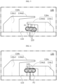
- FIG. 6 is a sectional view corresponding to FIG. 4 and schematically showing a fixing portion of a battery pack according to the third embodiment of the present disclosure.
- the battery pack 100 may further include a fixing protrusion P2 at the sidewall portion 133 of the cell frame 130, compared with the battery pack 100 of FIG. 4 .
- the fixing protrusion P2 may be formed on one surface of the sidewall portion 133 facing the sensing wire 120.
- the fixing protrusion P2 may be configured to press the sensing wire 120 located inside the first fixing portion 134a toward the first bending part 134d1. That is, the fixing protrusion P2 may be configured to fix the position of the sensing wire 120 accommodated inside the first fixing portion 134a.
- the present disclosure since the present disclosure includes the guide portion 135 having the inclined surface 135a on the second fixing portion 134b, when the sensing wire 120 is moved to the inside of the first fixing portion 134a, the sensing wire 120 may be easily fixed in place along the inclined surface 135a of the guide portion 135. Moreover, in the present disclosure, the guide portion 135 may prevent the sensing wire 120 located inside the first fixing portion 134a from being moved in the front and rear direction. Accordingly, according to the present disclosure, the sensing wire 120 may stably maintain a fixed state inside the first fixing portion 134a.
- the fixing portion 134 of the battery pack 100 may include a reinforcing rib R.
- the reinforcing rib R may be provided to at least one of the first pillar part 134c1 and the second pillar part 134c2.
- the reinforcing rib R may be provided to the first pillar part 134c1 and the second pillar part 134c2.
- the reinforcing rib R may extend forward from the first pillar part 134c1 to the sidewall portion 133.
- the reinforcing rib R may extend rearward from the second pillar part 134c2 to the sidewall portion 133.
- the present disclosure since the present disclosure includes the reinforcing rib R provided to the fixing portion 134, when the fixing portion 134 collides with an external object, the fixing portion 134 may not be easily damaged due to the reinforcing rib R. Accordingly, the battery pack 100 of the present disclosure may effectively increase the durability of the cell frame 130.
- the fixing portion 134 of the battery pack 100 according to the fifth embodiment of the present disclosure may further include a hook H, compared with the fixing portion 134 of FIG. 4 .
- the fixing portion 134 of the battery pack 100 according to the fifth embodiment of the present disclosure may include a pillar part 134c and a bending part 134d, like the fixing portion 134 of FIG. 3 .
- the hook H may be formed to extend from the end of the bending part 134d.
- the hook H may have a bent shape to cover one side of the sensing wire 120. That is, the hook H may be configured to prevent the sensing wire 120 located inside the fixing portion 134 from escaping from the fixing portion 134 to the outside again.
- the present disclosure further includes the hook H provided to the fixing portion 134, it is possible to more stably fix the sensing wire 120 located inside the fixing portion 134.
- the battery pack 100 further includes various devices (not shown) for controlling the charging and discharging of the battery pack 100, for example, a BMS (Battery Management System), a current sensor, and a fuse.
- a BMS Battery Management System
- a current sensor for example, a MEMS (Mattery Management System)
- a fuse for example, a fuse.
- an electronic device (not shown) according to an embodiment of the present disclosure includes at least one battery packs 100 described above.
- the electronic device may further include a device housing (not shown) having an accommodation space for accommodating the battery pack 100 and a display unit through which a user may check the state of charge of the battery pack 100.
- At least one battery pack 100 according to an embodiment of the present disclosure may be included in a vehicle such as an electric vehicle or a hybrid electric vehicle. That is, the battery pack 100 according to an embodiment of the present disclosure as described above may be mounted in a vehicle body of the vehicle according to an embodiment of the present disclosure.
- Reference Signs 100 battery pack 110: battery cell 160: measuring unit 120: sensing wire 121, 122: current sensing wire, temperature sensing wire 130: cell frame 131, 132: first frame, second frame 133: sidewall portion 134, 134a, 134b: fixing portion, first fixing portion, second fixing portion 134c, 134c1, 134c2: pillar part, first pillar part, second pillar part 134d, 134d1, 134d2: bending part, first bending part, second bending part P1, P2: pressing protrusion, fixing protrusion H: hook 135: guide portion R: reinforcing rib 170: metal plate
Landscapes
- Chemical & Material Sciences (AREA)
- Chemical Kinetics & Catalysis (AREA)
- Electrochemistry (AREA)
- General Chemical & Material Sciences (AREA)
- Engineering & Computer Science (AREA)
- Manufacturing & Machinery (AREA)
- Aviation & Aerospace Engineering (AREA)
- Battery Mounting, Suspending (AREA)
- Connection Of Batteries Or Terminals (AREA)
Abstract
Description
- The present application claims priority to
Korean Patent Application No. 10-2020-0137094 filed on October 21, 2020 - The present disclosure relates to a battery pack, an electronic device, and a vehicle, and more particularly, to a battery pack for securing easy installation of sensing wires and reducing manufacturing cost.
- Recently, with the rapid increase in demand for portable electronic products such as laptop computers, video cameras, and mobile phones and the extensive development of electric vehicles, accumulators for energy storage, robots and satellites, many studies are being made on high performance secondary batteries that can be repeatedly recharged.
- Currently, commercially available secondary batteries include nickel-cadmium batteries, nickel-hydrogen batteries, nickel-zinc batteries, lithium secondary batteries and the like, and among them, lithium secondary batteries have little or no memory effect, and thus they are gaining more attention than nickel-based secondary batteries for their advantages that recharging can be done whenever it is convenient, the self-discharge rate is very low and the energy density is high.
- These lithium secondary battery mainly uses lithium-based oxide and carbon material as a positive electrode active material and a negative electrode active material, respectively. In addition, this lithium secondary battery includes an electrode assembly in which a positive electrode plate and a negative electrode plate respectively coated with the positive electrode active material and the negative electrode active material are disposed with a separator interposed therebetween, and an exterior, namely a battery case, for hermetically accommodating the electrode assembly together with an electrolyte.
- In addition, depending on the shape of the exterior, lithium secondary batteries may be classified into a can-type battery cell in which the electrode assembly is included in a metal can and a pouch-type battery cell in which the electrode assembly is included in a pouch made of an aluminum laminate sheet.
- Here, in case of the can-type battery cell, the metal can in which the electrode assembly is included may be made in a cylindrical shape. The can-type battery cell may be used to construct a battery pack. For example, the battery pack may include a plurality of can-type battery cells, a cell frame for accommodating the battery cells, and a bus bar or a metal plate configured to electrically connect the plurality of battery cells.
- Meanwhile, the battery pack of the prior art basically measures the current and temperature changes according to the charging and discharging of a plurality of battery cells in order to determine the battery operating state or battery life. The battery pack of the prior art uses a current sensing wire to measure the current of a plurality of battery cells, and a temperature sensing wire to measure the temperature. At this time, in the battery pack of the prior art, the current sensing wire and the temperature sensing wire are fixed to the outer surface of the cell frame by using a double-sided tape.
- However, in the prior art, if the double-sided tape is used to prevent the movement of the sensing wires, first, the double-sided tape should be installed to surround the sensing wires, and then a release paper should be removed from the double-sided tape for adhesion with the cell frame. In this way, the work for fixing the sensing wires by using double-sided tape is cumbersome, thereby increasing the processing time and increasing the manufacturing cost.
- The present disclosure is designed to solve the problems of the related art, and therefore the present disclosure is directed to providing a battery pack for securing easy installation of sensing wires and reducing manufacturing cost.
- These and other objects and advantages of the present disclosure may be understood from the following detailed description and will become more fully apparent from the exemplary embodiments of the present disclosure. Also, it will be easily understood that the objects and advantages of the present disclosure may be realized by the means shown in the appended claims and combinations thereof.
- In one aspect of the present disclosure, there is provided a battery pack, comprising:
- a plurality of battery cells;
- a measuring unit configured to measure a current and temperature of at least one of the plurality of battery cells;
- at least one sensing wire electrically connected to the measuring unit and configured to have a wire on which a current flows; and
- a cell frame including a sidewall portion configured to form an inner space for accommodating the plurality of battery cells, and a fixing portion having a pillar part configured to protrude outward from the sidewall portion and a bending part bent and extended from the protruding end of the pillar part to form a space for accommodating the at least one sensing wire.
- Also, the fixing portion may include:
- a first fixing portion having a first pillar part located at one side with respect to the sensing wire and configured to protrude outward from the sidewall portion, and a first bending part bent and extended from the protruding end of the first pillar part to surround the sensing wire; and
- a second fixing portion having a second pillar part located at the other side with respect to the sensing wire and configured to protrude outward from the sidewall portion, and a second bending part bent and extended from the protruding end of the second pillar part and located to face the first bending part to be spaced apart from the first bending part by a predetermined distance.
- Moreover, the second pillar part may be spaced apart from an end of the first bending part by a predetermined distance.
- In addition, the first bending part may further include a pressing protrusion on one surface thereof facing the sensing wire.
- Further, the sidewall portion may further include a fixing protrusion configured to protrude toward the sensing wire.
- Also, the battery pack may further comprise a guide portion configured to protrude toward the sensing wire from the second pillar part of the second fixing portion and have an inclined surface so that a length of the guide portion protruding from the sidewall portion gradually decreases as being closer to the sensing wire.
- Moreover, at least one of the first pillar part and the second pillar part may include a reinforcing rib configured to extend to the sidewall portion.
- In addition, the fixing portion may include a hook configured to extend from an end of the bending part to surround one side portion of the sensing wire.
- Further, in another aspect of the present disclosure, there is also provided an electronic device, comprising at least one battery pack.
- Also, in another aspect of the present disclosure, there is also provided a vehicle, comprising at least one battery pack.
- According to an embodiment of the present disclosure, the battery pack of the present disclosure includes a fixing portion having a space for accommodating at least one wire, and thus it is possible to accommodate and fix the wire in the cell frame even without using an adhesive tape (double-sided tape), unlike the battery pack of the prior art. Thus, the process of manually attaching the wire to the outer surface of the cell frame by using an adhesive tape may be omitted, thereby effectively reducing the manufacturing cost and the manufacturing process time.
- The accompanying drawings illustrate a preferred embodiment of the present disclosure and together with the foregoing disclosure, serve to provide further understanding of the technical features of the present disclosure, and thus, the present disclosure is not construed as being limited to the drawing.
-
FIG. 1 is a perspective view schematically showing a battery pack according to the first embodiment of the present disclosure. -
FIG. 2 is an exploded perspective view schematically showing components of the battery pack according to the first embodiment of the present disclosure. -
FIG. 3 is a partial perspective enlarged view showing a fixing portion ofFIG. 1 . -
FIG. 4 is a sectional view schematically showing the fixing portion ofFIG. 3 . -
FIG. 5 is a sectional view corresponding toFIG. 4 and schematically showing a fixing portion of a battery pack according to the second embodiment of the present disclosure. -
FIG. 6 is a sectional view corresponding toFIG. 4 and schematically showing a fixing portion of a battery pack according to the third embodiment of the present disclosure. -
FIG. 7 is a sectional view corresponding toFIG. 4 and schematically showing a fixing portion of a battery pack according to the fourth embodiment of the present disclosure. -
FIG. 8 is a sectional view corresponding toFIG. 4 and schematically showing a fixing portion of a battery pack according to the fifth embodiment of the present disclosure. - Hereinafter, preferred embodiments of the present disclosure will be described in detail with reference to the accompanying drawings. Prior to the description, it should be understood that the terms used in the specification and the appended claims should not be construed as limited to general and dictionary meanings, but interpreted based on the meanings and concepts corresponding to technical aspects of the present disclosure on the basis of the principle that the inventor is allowed to define terms appropriately for the best explanation.
- Therefore, the description proposed herein is just a preferable example for the purpose of illustrations only, not intended to limit the scope of the disclosure, so it should be understood that other equivalents and modifications could be made thereto without departing from the scope of the disclosure.
-
FIG. 1 is a perspective view schematically showing a battery pack according to the first embodiment of the present disclosure. Also,FIG. 2 is an exploded perspective view schematically showing components of the battery pack according to the first embodiment of the present disclosure. - Referring to
FIGS. 1 to 3 , thebattery pack 100 according to the first embodiment of the present disclosure includes a plurality ofbattery cells 110, ameasuring unit 160, at least onesensing wire 120, and acell frame 130. - First, each of the plurality of
battery cells 110 may be a rechargeable lithium secondary battery. Thebattery cell 110 may be a can-type battery cell 110. Thebattery cell 110 may include apositive electrode terminal 111 and anegative electrode terminal 112 at one end and the other end thereof, respectively. Thebattery cell 110 may include a cylindrical can. - The configuration of the
battery cell 110 is widely known to those skilled in the art at the time of filing of this application and thus will not be described in detail here. In addition, although an example of thebattery cell 110 is illustrated inFIG. 3 , thebattery pack 100 according to the present disclosure is not limited to the configuration of thebattery cell 110 having a specific shape. That is, various types ofbattery cells 110 known at the time of filing of this application may be employed in thebattery pack 100 according to the present disclosure. - In addition, the
battery pack 100 of the present disclosure may further include a plurality ofmetal plates 170. Themetal plate 170 may be configured to electrically connect the plurality ofcylindrical battery cells 110. Themetal plate 170 may include a conductive metal. Themetal plate 170 may include, for example, at least one of copper, nickel, and aluminum. - Moreover, the
metal plate 170 may be mounted to a left side or a right side of thecell frame 130. For example, as shown inFIG. 2 , fourmetal plates 170 may be mounted at the right side of thebattery pack 100. - In addition, the measuring
unit 160 may be configured to measure a current and temperature of at least one of the plurality ofbattery cells 110. - Further, the at least one
sensing wire 120 may include acurrent sensing wire 121 for sensing a current of the plurality ofbattery cells 110 and atemperature sensing wire 122 for sensing a temperature of the plurality ofbattery cells 110. Thecurrent sensing wire 121 may be configured to transmit the current of at least one of the plurality ofbattery cells 110 to the measuringunit 160. Thecurrent sensing wire 121 may include a wire electrically connected to at least some of the plurality ofbattery cells 110. Thecurrent sensing wire 121 may be configured to contact a portion of themetal plate 170 through a ring terminal provided at an end thereof. - In addition, the
temperature sensing wire 122 may be configured to measure the temperature of at least some of the plurality ofbattery cells 110. For example, a thermistor may be provided at a lower end of thetemperature sensing wire 122. Accordingly, the measuringunit 160 may be configured to calculate the temperature of thebattery cell 110 through the electrical signal received from the thermistor. - Moreover, the measuring
unit 160 may have a connector C configured to connect with thecurrent sensing wire 121 and thetemperature sensing wire 122. The measuringunit 160 may be configured to calculate the temperature of thebattery cell 110 through the electrical signal received from thecurrent sensing wire 122. The measuringunit 160 may be configured to calculate the current intensity of thebattery cell 110 through the current transmitted from thecurrent sensing wire 121. - In addition, the
cell frame 130 may have an electrically insulating material. For example, thecell frame 130 may include polyvinyl chloride. Thecell frame 130 may include asidewall portion 133. Thesidewall portion 133 may be configured to form an inner space that accommodates the plurality ofbattery cells 110. For example, as shown inFIG. 1 , thesidewall portion 133 may include a front wall positioned in the front, a rear wall positioned in the rear, a left wall positioned on the left, and a right wall positioned on the right. In addition, thecell frame 130 may include an upper wall for covering the upper portion of the plurality ofbattery cells 110 and a lower wall for covering the lower portion of the plurality ofbattery cells 110. For reference, the positive direction of the X-axis and the negative direction of the X-axis indicated inFIG. 1 of the present disclosure may refer to a right direction and a left direction. The positive direction of the Y-axis and the negative direction of the Y-axis may refer to a rear direction and a front direction. The positive direction of the Z axis and the negative direction of the Z axis may refer to an upper direction and a lower direction. - Moreover, the
cell frame 130 may have a box-shaped body as a whole. In addition, thecell frame 130 may have a plurality of hollows O in the body thereof to accommodate the plurality ofbattery cells 110 therein. For example, thecell frame 130 may have a plurality of cylindrical hollows O, as shown inFIG. 2 . - In addition, the
cell frame 130 may include afirst frame 131 and asecond frame 132 that form a space for accommodating the plurality ofcylindrical battery cells 110. Thefirst frame 131 may be configured to have a rear end coupled to a front end of thesecond frame 132. In this case, the coupling method may be, for example, bolting. -
FIG. 3 is a partial perspective enlarged view showing a fixing portion ofFIG. 1 . - Moreover, the
cell frame 130 may include a fixingportion 134. The fixingportion 134 may include apillar part 134c and the bendingpart 134d. Thepillar part 134c may have a shape protruding outward from thesidewall portion 133. For example, as shown inFIG. 3 , thepillar part 134c may have a shape extending in the right direction from the right wall of thecell frame 130. - Also, the bending
part 134d may be bent and extended from the protruding end of thepillar part 134c. For example, as shown inFIG. 3 , the bendingpart 134d may have a shape extending forward or downward from the right wall of thecell frame 130. The bendingpart 134d may be configured to form a space for accommodating the at least onesensing wire 120. For example, as shown inFIG. 3 , three sensingwires 120 may be positioned inside the bendingpart 134d. Here, the term 'inside' means an area in which the plurality ofcylindrical battery cells 110 accommodated in thecell frame 130 are located. Further, the bendingpart 134d may prevent the at least onesensing wire 120 accommodated in the inside from being separated to the outside again due to its shape feature. - Therefore, according to this configuration of the present disclosure, since the present disclosure includes the fixing
portion 134 having a space for accommodating the at least onesensing wire 120, unlike thebattery pack 100 of the prior art, thesensing wire 120 may be accommodated in and fixed to thecell frame 130 without using an adhesive tape. Thus, the process for a worker to manually attach thesensing wire 120 to the outer surface of thecell frame 130 using an adhesive tape may be omitted, thereby effectively reducing the manufacturing cost and the manufacturing process time. -
FIG. 4 is a sectional view schematically showing the fixing portion ofFIG. 3 . InFIG. 4 , a part of the battery pack is cut in the horizontal direction and viewed downward from the top. - Referring to
FIG. 4 along withFIG. 3 , the fixingportion 134 of thebattery pack 100 according to an embodiment of the present disclosure may include afirst fixing portion 134a and asecond fixing portion 134b. - First, the
first fixing portion 134a may be positioned at one side with respect to thesensing wire 120. For example, thefirst fixing portion 134a may be positioned in front of thesensing wire 120. Thefirst fixing portion 134a may include a first pillar part 134c1 and a first bending part 134d1. The first pillar part 134c1 may protrude outward from thesidewall portion 133. For example, as shown inFIG. 4 , the first pillar part 134c1 may be provided to thesidewall portion 133 and may have a shape extending in the right direction from thesidewall portion 133. - Also, the first bending part 134d1 may be a portion bent and extended from the protruding end of the first pillar part 134c1. The first bending part 134d1 may have a bent shape to surround a portion of the
sensing wire 120. The bending direction of the first bending part 134d1 may be a rearward direction (a positive direction of the Y-axis). For example, as shown inFIG. 4 , thefirst fixing portion 134a may be provided to thefirst frame 131. - Moreover, the
second fixing portion 134b may be located at the other side with respect to thesensing wire 120. For example, thesecond fixing portion 134b may be positioned in front of thesensing wire 120. Thesecond fixing portion 134b may include a second pillar part 134c2 and a second bending part 134d2. The second pillar part 134c2 may protrude outward from thesidewall portion 133. For example, as shown inFIG. 4 , the second pillar part 134c2 may be provided to thesidewall portion 133 and may have a shape extending in the right direction from thesidewall portion 133. - Also, the second bending part 134d2 may be a portion bent and extended from the protruding end of the second pillar part 134c2. The second bending part 134d2 may have a bent shape to cover a portion of the
sensing wire 120. The bending direction of the second bending part 134d2 may be a forward direction (a negative direction of the Y-axis). For example, as shown inFIG. 4 , thesecond fixing portion 134b may be provided to thesecond frame 132. - Further, the second bending part 134d2 may be positioned to face the first bending part 134d1. The second bending part 134d2 may be positioned to be spaced apart from the first bending part 134d1 by a predetermined distance in an outer direction. The size of the space in which the first bending part 134d1 and the second bending part 134d2 are spaced apart from each other may be greater than the thickness of the
sensing wire 120. - In addition, the second pillar part 134c2 may be spaced apart from the end of the first bending part 134d1 by a predetermined distance. For example, as shown in
FIG. 4 , the second pillar part 134c2 may be spaced apart from the end of the first bending part 134d1 in the front and rear direction (Y direction). In this case, the size of the separated space may be equal to or greater than the thickness of thesensing wire 120. - Therefore, according to this configuration of the present disclosure, since the present disclosure includes the
first fixing portion 134a and thesecond fixing portion 134b, it is possible to doubly cover and protect a portion of thesensing wire 120 from the outside. Thus, when an external impact is applied to thebattery pack 100, it is possible to protect thesensing wire 120 from being damaged by external objects. Moreover, in the present disclosure, by moving thesensing wire 120 through the separated space of thefirst fixing portion 134a and thesecond fixing portion 134b, thesensing wire 120 may be safely accommodated at the inside of the first bending part 134d1 of thefirst fixing portion 134a. Further, in the present disclosure, since thesensing wire 120 accommodated inside the first bending part 134d1 of thefirst fixing portion 134a is not easily separated to the outside due to a zigzag-shaped moving space formed by thefirst fixing portion 134a and thesecond fixing portion 134b, thesensing wire 120 may stably maintain its position fixed inside thefirst fixing portion 134a. -
FIG. 5 is a sectional view corresponding toFIG. 4 and schematically showing a fixing portion of a battery pack according to the second embodiment of the present disclosure. - Referring to
FIG. 5 , thefirst fixing portion 134a of thebattery pack 100 according to the second embodiment of the present disclosure may further include a pressing protrusion P1, compared with thefirst fixing portion 134a ofFIG. 4 . Specifically, the pressing protrusion P1 may be formed on one surface of the first bending part 134d1 facing thesensing wire 120. The pressing protrusion P1 may be configured to press thesensing wire 120 located inside the first bending part 134d1 toward thesidewall portion 133. That is, the pressing protrusion P1 may be configured to fix the position of thesensing wire 120 accommodated inside the first bending part 134d1. - Therefore, according to this configuration of the present disclosure, since the present disclosure further includes the pressing protrusion P1 on one surface of the first bending part 134d1, the
sensing wire 120 may stably maintain its fixed state inside thefirst fixing portion 134a. Accordingly, in the present disclosure, thesensing wire 120 may be fixed to thecell frame 130 without a separate fixing member such as an adhesive tape, thereby shortening the manufacturing process of thebattery pack 100 and reducing the manufacturing cost. -
FIG. 6 is a sectional view corresponding toFIG. 4 and schematically showing a fixing portion of a battery pack according to the third embodiment of the present disclosure. - Referring to
FIG. 6 , thebattery pack 100 according to the third embodiment of the present disclosure may further include a fixing protrusion P2 at thesidewall portion 133 of thecell frame 130, compared with thebattery pack 100 ofFIG. 4 . Specifically, the fixing protrusion P2 may be formed on one surface of thesidewall portion 133 facing thesensing wire 120. The fixing protrusion P2 may be configured to press thesensing wire 120 located inside thefirst fixing portion 134a toward the first bending part 134d1. That is, the fixing protrusion P2 may be configured to fix the position of thesensing wire 120 accommodated inside thefirst fixing portion 134a. - Therefore, according to this configuration of the present disclosure, since the present disclosure further includes the fixing protrusion P2 on one surface of the
sidewall portion 133, thesensing wire 120 may stably maintain its fixed state inside thefirst fixing portion 134a. Accordingly, in the present disclosure, thesensing wire 120 may be fixed to thecell frame 130 without a separate fixing member such as an adhesive tape, thereby shortening the manufacturing process of thebattery pack 100 and reducing the manufacturing cost. -
FIG. 7 is a sectional view corresponding toFIG. 4 and schematically showing a fixing portion of a battery pack according to the fourth embodiment of the present disclosure. - Referring to
FIG. 7 , thebattery pack 100 according to the fourth embodiment of the present disclosure may further include aguide portion 135, compared with thebattery pack 100 ofFIG. 4 . Specifically, theguide portion 135 may protrude toward thesensing wire 120 from the second pillar part 134c2 of thesecond fixing portion 134b. For example, theguide portion 135 may be a portion protruding forward from the inner surface of thesecond fixing portion 134b. Theguide portion 135 may have aninclined surface 135a whose length protruding from thesidewall portion 133 gradually decreases as being closer to thesensing wire 120. That is, theguide portion 135 may have the shape of a triangular block with theinclined surface 135a. Theinclined surface 135a may be configured to be gradually closer to thesidewall portion 133 toward the front. - Therefore, according to this configuration of the present disclosure, since the present disclosure includes the
guide portion 135 having theinclined surface 135a on thesecond fixing portion 134b, when thesensing wire 120 is moved to the inside of thefirst fixing portion 134a, thesensing wire 120 may be easily fixed in place along theinclined surface 135a of theguide portion 135. Moreover, in the present disclosure, theguide portion 135 may prevent thesensing wire 120 located inside thefirst fixing portion 134a from being moved in the front and rear direction. Accordingly, according to the present disclosure, thesensing wire 120 may stably maintain a fixed state inside thefirst fixing portion 134a. - Meanwhile, referring to
FIG. 3 again, the fixingportion 134 of thebattery pack 100 according to the first embodiment of the present disclosure may include a reinforcing rib R. The reinforcing rib R may be provided to at least one of the first pillar part 134c1 and the second pillar part 134c2. For example, as shown inFIG. 3 , the reinforcing rib R may be provided to the first pillar part 134c1 and the second pillar part 134c2. The reinforcing rib R may extend forward from the first pillar part 134c1 to thesidewall portion 133. The reinforcing rib R may extend rearward from the second pillar part 134c2 to thesidewall portion 133. - Therefore, according to this configuration of the present disclosure, since the present disclosure includes the reinforcing rib R provided to the fixing
portion 134, when the fixingportion 134 collides with an external object, the fixingportion 134 may not be easily damaged due to the reinforcing rib R. Accordingly, thebattery pack 100 of the present disclosure may effectively increase the durability of thecell frame 130. -
FIG. 8 is a sectional view corresponding toFIG. 4 and schematically showing a fixing portion of a battery pack according to the fifth embodiment of the present disclosure. - Referring to
FIG. 8 , the fixingportion 134 of thebattery pack 100 according to the fifth embodiment of the present disclosure may further include a hook H, compared with the fixingportion 134 ofFIG. 4 . Specifically, the fixingportion 134 of thebattery pack 100 according to the fifth embodiment of the present disclosure may include apillar part 134c and abending part 134d, like the fixingportion 134 ofFIG. 3 . The hook H may be formed to extend from the end of the bendingpart 134d. The hook H may have a bent shape to cover one side of thesensing wire 120. That is, the hook H may be configured to prevent thesensing wire 120 located inside the fixingportion 134 from escaping from the fixingportion 134 to the outside again. - Therefore, according to this configuration of the present disclosure, since the present disclosure further includes the hook H provided to the fixing
portion 134, it is possible to more stably fix thesensing wire 120 located inside the fixingportion 134. - Meanwhile, the
battery pack 100 according to an embodiment of the present disclosure further includes various devices (not shown) for controlling the charging and discharging of thebattery pack 100, for example, a BMS (Battery Management System), a current sensor, and a fuse. - Meanwhile, an electronic device (not shown) according to an embodiment of the present disclosure includes at least one battery packs 100 described above. The electronic device may further include a device housing (not shown) having an accommodation space for accommodating the
battery pack 100 and a display unit through which a user may check the state of charge of thebattery pack 100. - In addition, at least one
battery pack 100 according to an embodiment of the present disclosure may be included in a vehicle such as an electric vehicle or a hybrid electric vehicle. That is, thebattery pack 100 according to an embodiment of the present disclosure as described above may be mounted in a vehicle body of the vehicle according to an embodiment of the present disclosure. - Meanwhile, even though the terms indicating directions such as upper, lower, left, right, front and rear directions are used in the specification, it is obvious to those skilled in the art that these merely represent relative positions for convenience in explanation and may vary based on a position of an observer or an object.
- Heretofore, embodiments and experimental examples has been described in detail to describe the present disclosure more specifically, but the present disclosure is not limited by these embodiments and experimental examples. The embodiments according to the present disclosure may be modified in various other forms, and the scope of the present disclosure should not be construed as being limited to the embodiments described above. The embodiments of the present disclosure are provided to more fully explain the present disclosure to those skilled in the art.
Reference Signs 100: battery pack 110: battery cell 160: measuring unit 120: sensing wire 121, 122: current sensing wire, temperature sensing wire 130: cell frame 131, 132: first frame, second frame 133: sidewall portion 134, 134a, 134b: fixing portion, first fixing portion, second fixing portion 134c, 134c1, 134c2: pillar part, first pillar part, second pillar part 134d, 134d1, 134d2: bending part, first bending part, second bending part P1, P2: pressing protrusion, fixing protrusion H: hook 135: guide portion R: reinforcing rib 170: metal plate
Claims (10)
- A battery pack, comprising:a plurality of battery cells;a measuring unit configured to measure a current and temperature of at least one of the plurality of battery cells;at least one sensing wire electrically connected to the measuring unit and configured to have a wire on which a current flows; anda cell frame including a sidewall portion configured to form an inner space for accommodating the plurality of battery cells, and a fixing portion having a pillar part configured to protrude outward from the sidewall portion and a bending part bent and extended from the protruding end of the pillar part to form a space for accommodating the at least one sensing wire.
- The battery pack according to claim 1,
wherein the fixing portion includes:a first fixing portion having a first pillar part located at one side with respect to the sensing wire and configured to protrude outward from the sidewall portion, and a first bending part bent and extended from the protruding end of the first pillar part to surround the sensing wire; anda second fixing portion having a second pillar part located at the other side with respect to the sensing wire and configured to protrude outward from the sidewall portion, and a second bending part bent and extended from the protruding end of the second pillar part and located to face the first bending part to be spaced apart from the first bending part by a predetermined distance. - The battery pack according to claim 2,
wherein the second pillar part is spaced apart from an end of the first bending part by a predetermined distance. - The battery pack according to claim 2,
wherein the first bending part further includes a pressing protrusion on one surface thereof facing the sensing wire. - The battery pack according to claim 2,
wherein the sidewall portion further includes a fixing protrusion configured to protrude toward the sensing wire. - The battery pack according to claim 2, further comprising:
a guide portion configured to protrude toward the sensing wire from the second pillar part of the second fixing portion and have an inclined surface so that a length of the guide portion protruding from the sidewall portion gradually decreases as being closer to the sensing wire. - The battery pack according to claim 2,
wherein at least one of the first pillar part and the second pillar part includes a reinforcing rib configured to extend to the sidewall portion. - The battery pack according to claim 1,
wherein the fixing portion includes a hook configured to extend from an end of the bending part to surround one side portion of the sensing wire. - An electronic device, comprising at least one battery pack according to any one of claims 1 to 8.
- A vehicle, comprising at least one battery pack according to any one of claims 1 to 8.
Applications Claiming Priority (2)
| Application Number | Priority Date | Filing Date | Title |
|---|---|---|---|
| KR1020200137094A KR102957149B1 (en) | 2020-10-21 | 2020-10-21 | Battery Pack, Electronic Device, and Vehicle |
| PCT/KR2021/012069 WO2022085937A1 (en) | 2020-10-21 | 2021-09-06 | Battery pack, electronic device, and vehicle |
Publications (2)
| Publication Number | Publication Date |
|---|---|
| EP4164025A1 true EP4164025A1 (en) | 2023-04-12 |
| EP4164025A4 EP4164025A4 (en) | 2025-01-22 |
Family
ID=81289922
Family Applications (1)
| Application Number | Title | Priority Date | Filing Date |
|---|---|---|---|
| EP21883010.7A Pending EP4164025A4 (en) | 2020-10-21 | 2021-09-06 | BATTERY PACK, ELECTRONIC DEVICE AND VEHICLE |
Country Status (7)
| Country | Link |
|---|---|
| US (1) | US12567609B2 (en) |
| EP (1) | EP4164025A4 (en) |
| JP (1) | JP7500769B2 (en) |
| KR (1) | KR102957149B1 (en) |
| CN (1) | CN115668582A (en) |
| TW (1) | TWI911310B (en) |
| WO (1) | WO2022085937A1 (en) |
Families Citing this family (3)
| Publication number | Priority date | Publication date | Assignee | Title |
|---|---|---|---|---|
| JP7821775B2 (en) * | 2021-02-25 | 2026-02-27 | 本田技研工業株式会社 | Battery pack |
| JP7697074B2 (en) * | 2023-02-10 | 2025-06-23 | 台達電子工業股▲ふん▼有限公司 | Battery module equipped with temperature detection structure |
| JP2026071799A (en) * | 2024-10-17 | 2026-04-30 | 株式会社Aescジャパン | Battery pack |
Family Cites Families (31)
| Publication number | Priority date | Publication date | Assignee | Title |
|---|---|---|---|---|
| US4857670A (en) * | 1988-01-28 | 1989-08-15 | Frank Richard E | Wiring duct unit |
| US6972367B2 (en) * | 2001-10-31 | 2005-12-06 | Hellermanntyton Corporation | Multi-channel raceway |
| KR100595304B1 (en) | 2001-12-26 | 2006-07-03 | 엘지.필립스 엘시디 주식회사 | Lamp wire fixing structure of LCD |
| KR100994231B1 (en) | 2004-03-02 | 2010-11-12 | 엘지디스플레이 주식회사 | Liquid crystal display device |
| JP5813302B2 (en) * | 2009-09-07 | 2015-11-17 | 矢崎総業株式会社 | Bus bar module and power supply device including the bus bar module |
| JP5550291B2 (en) * | 2009-09-17 | 2014-07-16 | 矢崎総業株式会社 | Electric wire arrangement, bus bar module, and power supply device |
| KR101084836B1 (en) | 2009-10-27 | 2011-11-21 | 삼성에스디아이 주식회사 | Battery pack |
| US8709628B2 (en) | 2010-09-02 | 2014-04-29 | Bathium Canada Inc. | Battery pack with connecting device |
| JP5598725B2 (en) | 2011-05-31 | 2014-10-01 | 株式会社オートネットワーク技術研究所 | Battery wiring module |
| JP2013020815A (en) * | 2011-07-11 | 2013-01-31 | Auto Network Gijutsu Kenkyusho:Kk | Battery wiring module |
| JP2013105571A (en) | 2011-11-11 | 2013-05-30 | Auto Network Gijutsu Kenkyusho:Kk | Battery wiring module |
| JP2013143214A (en) | 2012-01-10 | 2013-07-22 | Auto Network Gijutsu Kenkyusho:Kk | Wiring module |
| JP5494748B2 (en) * | 2012-07-18 | 2014-05-21 | 株式会社オートネットワーク技術研究所 | Battery wiring module |
| JP6118176B2 (en) * | 2013-05-29 | 2017-04-19 | 矢崎総業株式会社 | Bus bar module and power supply |
| JP6310337B2 (en) | 2014-06-20 | 2018-04-11 | 矢崎総業株式会社 | Resin plate and bus bar module |
| KR101702505B1 (en) | 2014-08-22 | 2017-02-03 | 주식회사 엘지화학 | Battery module and battery pack including the same |
| JP6372417B2 (en) | 2015-04-14 | 2018-08-15 | 住友電装株式会社 | Battery wiring module |
| KR102117318B1 (en) | 2015-07-21 | 2020-06-01 | 주식회사 엘지화학 | Battery Module Comprising Battery Cell Stack of Step-formed Structure |
| KR102047483B1 (en) * | 2015-10-30 | 2019-12-02 | 주식회사 엘지화학 | Battery module and battery pack including the same |
| JP2017212128A (en) | 2016-05-26 | 2017-11-30 | 株式会社オートネットワーク技術研究所 | Connection module |
| KR101879863B1 (en) | 2016-06-08 | 2018-08-17 | 주식회사 경신 | Battery pack mounting type protector |
| JP6724627B2 (en) | 2016-07-22 | 2020-07-15 | 株式会社オートネットワーク技術研究所 | Wiring module |
| KR20180039526A (en) * | 2016-10-10 | 2018-04-18 | 한국단자공업 주식회사 | Cell-busbar and connection apparatus of battery module using this |
| KR102256600B1 (en) * | 2017-02-16 | 2021-05-26 | 주식회사 엘지에너지솔루션 | Battery module, battery pack comprising the battery module and vehicle comprising the battery pack |
| KR102097087B1 (en) | 2017-04-07 | 2020-04-03 | 주식회사 엘지화학 | Battery module, battery pack including the same, and vehicle including the same |
| JP6675349B2 (en) | 2017-05-19 | 2020-04-01 | 矢崎総業株式会社 | Busbar module |
| JP6605536B2 (en) * | 2017-06-08 | 2019-11-13 | 矢崎総業株式会社 | Bus bar module and power supply |
| KR102169632B1 (en) | 2017-07-28 | 2020-10-23 | 주식회사 엘지화학 | Battery module, battery pack and energy storage system comprising the same |
| KR20190112468A (en) | 2018-03-26 | 2019-10-07 | 에이치엘그린파워 주식회사 | Battery cartridge |
| KR102259380B1 (en) | 2018-04-20 | 2021-06-01 | 주식회사 엘지에너지솔루션 | Battery Module Having Bus-bar and Battery Pack |
| KR20200137094A (en) | 2019-05-29 | 2020-12-09 | 주식회사 코리아조인트 | Pipe coupling easy installed |
-
2020
- 2020-10-21 KR KR1020200137094A patent/KR102957149B1/en active Active
-
2021
- 2021-09-06 WO PCT/KR2021/012069 patent/WO2022085937A1/en not_active Ceased
- 2021-09-06 JP JP2022565909A patent/JP7500769B2/en active Active
- 2021-09-06 EP EP21883010.7A patent/EP4164025A4/en active Pending
- 2021-09-06 US US18/008,366 patent/US12567609B2/en active Active
- 2021-09-06 CN CN202180035767.6A patent/CN115668582A/en active Pending
- 2021-10-20 TW TW110138857A patent/TWI911310B/en active
Also Published As
| Publication number | Publication date |
|---|---|
| JP7500769B2 (en) | 2024-06-17 |
| TW202220262A (en) | 2022-05-16 |
| WO2022085937A1 (en) | 2022-04-28 |
| US12567609B2 (en) | 2026-03-03 |
| KR20220052773A (en) | 2022-04-28 |
| KR102957149B1 (en) | 2026-04-23 |
| EP4164025A4 (en) | 2025-01-22 |
| TWI911310B (en) | 2026-01-11 |
| CN115668582A (en) | 2023-01-31 |
| US20230291019A1 (en) | 2023-09-14 |
| JP2023524002A (en) | 2023-06-08 |
Similar Documents
| Publication | Publication Date | Title |
|---|---|---|
| JP6496455B2 (en) | Battery module and battery pack including the same | |
| US12567609B2 (en) | Battery pack, electronic device and vehicle | |
| EP4053989A1 (en) | Battery module having busbar, battery pack and vehicle | |
| KR20170050508A (en) | Battery module and battery pack including the same | |
| CN114175389A (en) | Battery pack, electronic device, and vehicle | |
| US20230045395A1 (en) | Battery module, battery pack comprising the same, and vehicle | |
| US20220344759A1 (en) | Battery module, battery pack comprising same, and vehicle | |
| KR20170050511A (en) | Battery module and battery pack including the same | |
| EP4187704A2 (en) | Battery module, battery pack, and vehicle | |
| US12592421B2 (en) | Battery pack, electronic device and vehicle | |
| EP4131574B1 (en) | Battery module, battery pack, and electric vehicle | |
| EP3671942B1 (en) | Terminal case having the improved function of estimating state of secondary battery | |
| EP3671941B1 (en) | Secondary battery and battery pack including the same | |
| EP4084188B1 (en) | Battery pack, electronic device and vehicle | |
| EP4216354B1 (en) | Battery module, battery pack, and vehicle including the same | |
| EP4187674A1 (en) | Battery pack, electronic device, automobile, and battery management system module | |
| CN116368393A (en) | Battery, electrical device and method of making battery | |
| TWI916431B (en) | Battery pack, electronic device and vehicle | |
| US20260031418A1 (en) | Battery module, battery pack and energy storage system | |
| KR20060073387A (en) | Secondary battery module with improved safety |
Legal Events
| Date | Code | Title | Description |
|---|---|---|---|
| STAA | Information on the status of an ep patent application or granted ep patent |
Free format text: STATUS: THE INTERNATIONAL PUBLICATION HAS BEEN MADE |
|
| PUAI | Public reference made under article 153(3) epc to a published international application that has entered the european phase |
Free format text: ORIGINAL CODE: 0009012 |
|
| STAA | Information on the status of an ep patent application or granted ep patent |
Free format text: STATUS: REQUEST FOR EXAMINATION WAS MADE |
|
| 17P | Request for examination filed |
Effective date: 20230103 |
|
| AK | Designated contracting states |
Kind code of ref document: A1 Designated state(s): AL AT BE BG CH CY CZ DE DK EE ES FI FR GB GR HR HU IE IS IT LI LT LU LV MC MK MT NL NO PL PT RO RS SE SI SK SM TR |
|
| DAV | Request for validation of the european patent (deleted) | ||
| DAX | Request for extension of the european patent (deleted) | ||
| A4 | Supplementary search report drawn up and despatched |
Effective date: 20250103 |
|
| RIC1 | Information provided on ipc code assigned before grant |
Ipc: H01M 50/213 20210101ALI20241219BHEP Ipc: H01M 50/20 20210101ALI20241219BHEP Ipc: H01M 10/48 20060101AFI20241219BHEP |
|
| GRAP | Despatch of communication of intention to grant a patent |
Free format text: ORIGINAL CODE: EPIDOSNIGR1 |
|
| STAA | Information on the status of an ep patent application or granted ep patent |
Free format text: STATUS: GRANT OF PATENT IS INTENDED |
|
| INTG | Intention to grant announced |
Effective date: 20260122 |