EP4163989A1 - Nanocomposite layer, method of forming nanocomposite layer and battery - Google Patents
Nanocomposite layer, method of forming nanocomposite layer and battery Download PDFInfo
- Publication number
- EP4163989A1 EP4163989A1 EP22164608.6A EP22164608A EP4163989A1 EP 4163989 A1 EP4163989 A1 EP 4163989A1 EP 22164608 A EP22164608 A EP 22164608A EP 4163989 A1 EP4163989 A1 EP 4163989A1
- Authority
- EP
- European Patent Office
- Prior art keywords
- polymer
- carbon nanotube
- nanoparticles
- nanocomposite layer
- nanocomposite
- Prior art date
- Legal status (The legal status is an assumption and is not a legal conclusion. Google has not performed a legal analysis and makes no representation as to the accuracy of the status listed.)
- Pending
Links
Images


Classifications
-
- H—ELECTRICITY
- H01—ELECTRIC ELEMENTS
- H01M—PROCESSES OR MEANS, e.g. BATTERIES, FOR THE DIRECT CONVERSION OF CHEMICAL ENERGY INTO ELECTRICAL ENERGY
- H01M10/00—Secondary cells; Manufacture thereof
- H01M10/42—Methods or arrangements for servicing or maintenance of secondary cells or secondary half-cells
- H01M10/4235—Safety or regulating additives or arrangements in electrodes, separators or electrolyte
-
- H—ELECTRICITY
- H01—ELECTRIC ELEMENTS
- H01M—PROCESSES OR MEANS, e.g. BATTERIES, FOR THE DIRECT CONVERSION OF CHEMICAL ENERGY INTO ELECTRICAL ENERGY
- H01M4/00—Electrodes
- H01M4/02—Electrodes composed of, or comprising, active material
- H01M4/62—Selection of inactive substances as ingredients for active masses, e.g. binders, fillers
- H01M4/624—Electric conductive fillers
- H01M4/625—Carbon or graphite
-
- H—ELECTRICITY
- H01—ELECTRIC ELEMENTS
- H01M—PROCESSES OR MEANS, e.g. BATTERIES, FOR THE DIRECT CONVERSION OF CHEMICAL ENERGY INTO ELECTRICAL ENERGY
- H01M10/00—Secondary cells; Manufacture thereof
- H01M10/05—Accumulators with non-aqueous electrolyte
- H01M10/052—Li-accumulators
- H01M10/0525—Rocking-chair batteries, i.e. batteries with lithium insertion or intercalation in both electrodes; Lithium-ion batteries
-
- H—ELECTRICITY
- H01—ELECTRIC ELEMENTS
- H01M—PROCESSES OR MEANS, e.g. BATTERIES, FOR THE DIRECT CONVERSION OF CHEMICAL ENERGY INTO ELECTRICAL ENERGY
- H01M4/00—Electrodes
- H01M4/02—Electrodes composed of, or comprising, active material
- H01M4/04—Processes of manufacture in general
- H01M4/0402—Methods of deposition of the material
- H01M4/0404—Methods of deposition of the material by coating on electrode collectors
-
- H—ELECTRICITY
- H01—ELECTRIC ELEMENTS
- H01M—PROCESSES OR MEANS, e.g. BATTERIES, FOR THE DIRECT CONVERSION OF CHEMICAL ENERGY INTO ELECTRICAL ENERGY
- H01M4/00—Electrodes
- H01M4/02—Electrodes composed of, or comprising, active material
- H01M4/04—Processes of manufacture in general
- H01M4/0402—Methods of deposition of the material
- H01M4/0407—Methods of deposition of the material by coating on an electrolyte layer
-
- H—ELECTRICITY
- H01—ELECTRIC ELEMENTS
- H01M—PROCESSES OR MEANS, e.g. BATTERIES, FOR THE DIRECT CONVERSION OF CHEMICAL ENERGY INTO ELECTRICAL ENERGY
- H01M4/00—Electrodes
- H01M4/02—Electrodes composed of, or comprising, active material
- H01M4/04—Processes of manufacture in general
- H01M4/0438—Processes of manufacture in general by electrochemical processing
- H01M4/044—Activating, forming or electrochemical attack of the supporting material
- H01M4/0445—Forming after manufacture of the electrode, e.g. first charge, cycling
- H01M4/0447—Forming after manufacture of the electrode, e.g. first charge, cycling of complete cells or cells stacks
-
- H—ELECTRICITY
- H01—ELECTRIC ELEMENTS
- H01M—PROCESSES OR MEANS, e.g. BATTERIES, FOR THE DIRECT CONVERSION OF CHEMICAL ENERGY INTO ELECTRICAL ENERGY
- H01M4/00—Electrodes
- H01M4/02—Electrodes composed of, or comprising, active material
- H01M4/04—Processes of manufacture in general
- H01M4/0471—Processes of manufacture in general involving thermal treatment, e.g. firing, sintering, backing particulate active material, thermal decomposition, pyrolysis
-
- H—ELECTRICITY
- H01—ELECTRIC ELEMENTS
- H01M—PROCESSES OR MEANS, e.g. BATTERIES, FOR THE DIRECT CONVERSION OF CHEMICAL ENERGY INTO ELECTRICAL ENERGY
- H01M4/00—Electrodes
- H01M4/02—Electrodes composed of, or comprising, active material
- H01M4/13—Electrodes for accumulators with non-aqueous electrolyte, e.g. for lithium-accumulators; Processes of manufacture thereof
- H01M4/139—Processes of manufacture
-
- H—ELECTRICITY
- H01—ELECTRIC ELEMENTS
- H01M—PROCESSES OR MEANS, e.g. BATTERIES, FOR THE DIRECT CONVERSION OF CHEMICAL ENERGY INTO ELECTRICAL ENERGY
- H01M4/00—Electrodes
- H01M4/02—Electrodes composed of, or comprising, active material
- H01M4/36—Selection of substances as active materials, active masses, active liquids
- H01M4/362—Composites
- H01M4/366—Composites as layered products
-
- H—ELECTRICITY
- H01—ELECTRIC ELEMENTS
- H01M—PROCESSES OR MEANS, e.g. BATTERIES, FOR THE DIRECT CONVERSION OF CHEMICAL ENERGY INTO ELECTRICAL ENERGY
- H01M4/00—Electrodes
- H01M4/02—Electrodes composed of, or comprising, active material
- H01M4/62—Selection of inactive substances as ingredients for active masses, e.g. binders, fillers
- H01M4/621—Binders
- H01M4/622—Binders being polymers
-
- H—ELECTRICITY
- H01—ELECTRIC ELEMENTS
- H01M—PROCESSES OR MEANS, e.g. BATTERIES, FOR THE DIRECT CONVERSION OF CHEMICAL ENERGY INTO ELECTRICAL ENERGY
- H01M50/00—Constructional details or processes of manufacture of the non-active parts of electrochemical cells other than fuel cells, e.g. hybrid cells
- H01M50/40—Separators; Membranes; Diaphragms; Spacing elements inside cells
- H01M50/403—Manufacturing processes of separators, membranes or diaphragms
-
- H—ELECTRICITY
- H01—ELECTRIC ELEMENTS
- H01M—PROCESSES OR MEANS, e.g. BATTERIES, FOR THE DIRECT CONVERSION OF CHEMICAL ENERGY INTO ELECTRICAL ENERGY
- H01M50/00—Constructional details or processes of manufacture of the non-active parts of electrochemical cells other than fuel cells, e.g. hybrid cells
- H01M50/40—Separators; Membranes; Diaphragms; Spacing elements inside cells
- H01M50/409—Separators, membranes or diaphragms characterised by the material
- H01M50/411—Organic material
- H01M50/414—Synthetic resins, e.g. thermoplastics or thermosetting resins
- H01M50/42—Acrylic resins
-
- H—ELECTRICITY
- H01—ELECTRIC ELEMENTS
- H01M—PROCESSES OR MEANS, e.g. BATTERIES, FOR THE DIRECT CONVERSION OF CHEMICAL ENERGY INTO ELECTRICAL ENERGY
- H01M50/00—Constructional details or processes of manufacture of the non-active parts of electrochemical cells other than fuel cells, e.g. hybrid cells
- H01M50/40—Separators; Membranes; Diaphragms; Spacing elements inside cells
- H01M50/409—Separators, membranes or diaphragms characterised by the material
- H01M50/411—Organic material
- H01M50/414—Synthetic resins, e.g. thermoplastics or thermosetting resins
- H01M50/423—Polyamide resins
-
- H—ELECTRICITY
- H01—ELECTRIC ELEMENTS
- H01M—PROCESSES OR MEANS, e.g. BATTERIES, FOR THE DIRECT CONVERSION OF CHEMICAL ENERGY INTO ELECTRICAL ENERGY
- H01M50/00—Constructional details or processes of manufacture of the non-active parts of electrochemical cells other than fuel cells, e.g. hybrid cells
- H01M50/40—Separators; Membranes; Diaphragms; Spacing elements inside cells
- H01M50/409—Separators, membranes or diaphragms characterised by the material
- H01M50/411—Organic material
- H01M50/414—Synthetic resins, e.g. thermoplastics or thermosetting resins
- H01M50/426—Fluorocarbon polymers
-
- H—ELECTRICITY
- H01—ELECTRIC ELEMENTS
- H01M—PROCESSES OR MEANS, e.g. BATTERIES, FOR THE DIRECT CONVERSION OF CHEMICAL ENERGY INTO ELECTRICAL ENERGY
- H01M50/00—Constructional details or processes of manufacture of the non-active parts of electrochemical cells other than fuel cells, e.g. hybrid cells
- H01M50/40—Separators; Membranes; Diaphragms; Spacing elements inside cells
- H01M50/409—Separators, membranes or diaphragms characterised by the material
- H01M50/443—Particulate material
-
- H—ELECTRICITY
- H01—ELECTRIC ELEMENTS
- H01M—PROCESSES OR MEANS, e.g. BATTERIES, FOR THE DIRECT CONVERSION OF CHEMICAL ENERGY INTO ELECTRICAL ENERGY
- H01M50/00—Constructional details or processes of manufacture of the non-active parts of electrochemical cells other than fuel cells, e.g. hybrid cells
- H01M50/40—Separators; Membranes; Diaphragms; Spacing elements inside cells
- H01M50/409—Separators, membranes or diaphragms characterised by the material
- H01M50/449—Separators, membranes or diaphragms characterised by the material having a layered structure
-
- H—ELECTRICITY
- H01—ELECTRIC ELEMENTS
- H01M—PROCESSES OR MEANS, e.g. BATTERIES, FOR THE DIRECT CONVERSION OF CHEMICAL ENERGY INTO ELECTRICAL ENERGY
- H01M10/00—Secondary cells; Manufacture thereof
- H01M10/05—Accumulators with non-aqueous electrolyte
- H01M10/056—Accumulators with non-aqueous electrolyte characterised by the materials used as electrolytes, e.g. mixed inorganic/organic electrolytes
- H01M10/0561—Accumulators with non-aqueous electrolyte characterised by the materials used as electrolytes, e.g. mixed inorganic/organic electrolytes the electrolyte being constituted of inorganic materials only
- H01M10/0562—Solid materials
-
- H—ELECTRICITY
- H01—ELECTRIC ELEMENTS
- H01M—PROCESSES OR MEANS, e.g. BATTERIES, FOR THE DIRECT CONVERSION OF CHEMICAL ENERGY INTO ELECTRICAL ENERGY
- H01M10/00—Secondary cells; Manufacture thereof
- H01M10/05—Accumulators with non-aqueous electrolyte
- H01M10/056—Accumulators with non-aqueous electrolyte characterised by the materials used as electrolytes, e.g. mixed inorganic/organic electrolytes
- H01M10/0564—Accumulators with non-aqueous electrolyte characterised by the materials used as electrolytes, e.g. mixed inorganic/organic electrolytes the electrolyte being constituted of organic materials only
- H01M10/0565—Polymeric materials, e.g. gel-type or solid-type
-
- H—ELECTRICITY
- H01—ELECTRIC ELEMENTS
- H01M—PROCESSES OR MEANS, e.g. BATTERIES, FOR THE DIRECT CONVERSION OF CHEMICAL ENERGY INTO ELECTRICAL ENERGY
- H01M4/00—Electrodes
- H01M4/02—Electrodes composed of, or comprising, active material
- H01M2004/026—Electrodes composed of, or comprising, active material characterised by the polarity
- H01M2004/027—Negative electrodes
-
- H—ELECTRICITY
- H01—ELECTRIC ELEMENTS
- H01M—PROCESSES OR MEANS, e.g. BATTERIES, FOR THE DIRECT CONVERSION OF CHEMICAL ENERGY INTO ELECTRICAL ENERGY
- H01M2300/00—Electrolytes
- H01M2300/0017—Non-aqueous electrolytes
- H01M2300/0065—Solid electrolytes
- H01M2300/0082—Organic polymers
-
- H—ELECTRICITY
- H01—ELECTRIC ELEMENTS
- H01M—PROCESSES OR MEANS, e.g. BATTERIES, FOR THE DIRECT CONVERSION OF CHEMICAL ENERGY INTO ELECTRICAL ENERGY
- H01M2300/00—Electrolytes
- H01M2300/0088—Composites
- H01M2300/0091—Composites in the form of mixtures
-
- H—ELECTRICITY
- H01—ELECTRIC ELEMENTS
- H01M—PROCESSES OR MEANS, e.g. BATTERIES, FOR THE DIRECT CONVERSION OF CHEMICAL ENERGY INTO ELECTRICAL ENERGY
- H01M2300/00—Electrolytes
- H01M2300/0088—Composites
- H01M2300/0094—Composites in the form of layered products, e.g. coatings
-
- H—ELECTRICITY
- H01—ELECTRIC ELEMENTS
- H01M—PROCESSES OR MEANS, e.g. BATTERIES, FOR THE DIRECT CONVERSION OF CHEMICAL ENERGY INTO ELECTRICAL ENERGY
- H01M4/00—Electrodes
- H01M4/02—Electrodes composed of, or comprising, active material
- H01M4/13—Electrodes for accumulators with non-aqueous electrolyte, e.g. for lithium-accumulators; Processes of manufacture thereof
- H01M4/133—Electrodes based on carbonaceous material, e.g. graphite-intercalation compounds or CFx
-
- H—ELECTRICITY
- H01—ELECTRIC ELEMENTS
- H01M—PROCESSES OR MEANS, e.g. BATTERIES, FOR THE DIRECT CONVERSION OF CHEMICAL ENERGY INTO ELECTRICAL ENERGY
- H01M4/00—Electrodes
- H01M4/02—Electrodes composed of, or comprising, active material
- H01M4/13—Electrodes for accumulators with non-aqueous electrolyte, e.g. for lithium-accumulators; Processes of manufacture thereof
- H01M4/134—Electrodes based on metals, Si or alloys
-
- H—ELECTRICITY
- H01—ELECTRIC ELEMENTS
- H01M—PROCESSES OR MEANS, e.g. BATTERIES, FOR THE DIRECT CONVERSION OF CHEMICAL ENERGY INTO ELECTRICAL ENERGY
- H01M4/00—Electrodes
- H01M4/02—Electrodes composed of, or comprising, active material
- H01M4/13—Electrodes for accumulators with non-aqueous electrolyte, e.g. for lithium-accumulators; Processes of manufacture thereof
- H01M4/139—Processes of manufacture
- H01M4/1393—Processes of manufacture of electrodes based on carbonaceous material, e.g. graphite-intercalation compounds or CFx
-
- H—ELECTRICITY
- H01—ELECTRIC ELEMENTS
- H01M—PROCESSES OR MEANS, e.g. BATTERIES, FOR THE DIRECT CONVERSION OF CHEMICAL ENERGY INTO ELECTRICAL ENERGY
- H01M4/00—Electrodes
- H01M4/02—Electrodes composed of, or comprising, active material
- H01M4/13—Electrodes for accumulators with non-aqueous electrolyte, e.g. for lithium-accumulators; Processes of manufacture thereof
- H01M4/139—Processes of manufacture
- H01M4/1395—Processes of manufacture of electrodes based on metals, Si or alloys
-
- H—ELECTRICITY
- H01—ELECTRIC ELEMENTS
- H01M—PROCESSES OR MEANS, e.g. BATTERIES, FOR THE DIRECT CONVERSION OF CHEMICAL ENERGY INTO ELECTRICAL ENERGY
- H01M4/00—Electrodes
- H01M4/02—Electrodes composed of, or comprising, active material
- H01M4/36—Selection of substances as active materials, active masses, active liquids
- H01M4/362—Composites
- H01M4/364—Composites as mixtures
-
- H—ELECTRICITY
- H01—ELECTRIC ELEMENTS
- H01M—PROCESSES OR MEANS, e.g. BATTERIES, FOR THE DIRECT CONVERSION OF CHEMICAL ENERGY INTO ELECTRICAL ENERGY
- H01M4/00—Electrodes
- H01M4/02—Electrodes composed of, or comprising, active material
- H01M4/36—Selection of substances as active materials, active masses, active liquids
- H01M4/38—Selection of substances as active materials, active masses, active liquids of elements or alloys
- H01M4/381—Alkaline or alkaline earth metals elements
- H01M4/382—Lithium
-
- H—ELECTRICITY
- H01—ELECTRIC ELEMENTS
- H01M—PROCESSES OR MEANS, e.g. BATTERIES, FOR THE DIRECT CONVERSION OF CHEMICAL ENERGY INTO ELECTRICAL ENERGY
- H01M4/00—Electrodes
- H01M4/02—Electrodes composed of, or comprising, active material
- H01M4/36—Selection of substances as active materials, active masses, active liquids
- H01M4/38—Selection of substances as active materials, active masses, active liquids of elements or alloys
- H01M4/386—Silicon or alloys based on silicon
-
- H—ELECTRICITY
- H01—ELECTRIC ELEMENTS
- H01M—PROCESSES OR MEANS, e.g. BATTERIES, FOR THE DIRECT CONVERSION OF CHEMICAL ENERGY INTO ELECTRICAL ENERGY
- H01M4/00—Electrodes
- H01M4/02—Electrodes composed of, or comprising, active material
- H01M4/36—Selection of substances as active materials, active masses, active liquids
- H01M4/58—Selection of substances as active materials, active masses, active liquids of inorganic compounds other than oxides or hydroxides, e.g. sulfides, selenides, tellurides, halogenides or LiCoFy; of polyanionic structures, e.g. phosphates, silicates or borates
- H01M4/583—Carbonaceous material, e.g. graphite-intercalation compounds or CFx
- H01M4/587—Carbonaceous material, e.g. graphite-intercalation compounds or CFx for inserting or intercalating light metals
-
- Y—GENERAL TAGGING OF NEW TECHNOLOGICAL DEVELOPMENTS; GENERAL TAGGING OF CROSS-SECTIONAL TECHNOLOGIES SPANNING OVER SEVERAL SECTIONS OF THE IPC; TECHNICAL SUBJECTS COVERED BY FORMER USPC CROSS-REFERENCE ART COLLECTIONS [XRACs] AND DIGESTS
- Y02—TECHNOLOGIES OR APPLICATIONS FOR MITIGATION OR ADAPTATION AGAINST CLIMATE CHANGE
- Y02E—REDUCTION OF GREENHOUSE GAS [GHG] EMISSIONS, RELATED TO ENERGY GENERATION, TRANSMISSION OR DISTRIBUTION
- Y02E60/00—Enabling technologies; Technologies with a potential or indirect contribution to GHG emissions mitigation
- Y02E60/10—Energy storage using batteries
Definitions
- the present invention relates to a nanocomposite layer, a method of forming nanocomposite layer and a battery. More particularly, the nanocomposite layer can be applied to batteries and is disposed on the negative electrode of the battery.
- Lithium-ion batteries have been widely used in electronic devices such as mobile phones and laptops. Currently, lithium-ion batteries are also used in electric vehicles as their power source.
- a lithium-ion battery is usually composed of a positive electrode, a negative electrode, and an electrolyte.
- the positive electrode which is also called as cathode, undergoes a reduction reaction during discharge to reduce conductive ions (e.g., Li + ) to uncharged atoms (e.g., Li).
- the negative electrode which is also called as anode, undergoes an oxidation reaction during discharge.
- lithium-ion batteries there are still many problems to overcome with lithium-ion batteries.
- the uneven deposition of the lithium ions after repeated charging and discharging causes formation of dendrites on the surface of the negative electrode.
- the penetration of dendrites through the electrode separator will lead to short circuit and cause safety hazards such as thermal failure and fire of the battery. Therefore, the development direction of lithium-ion battery is to improve the energy density and safety of the battery.
- a nanocomposite layer for battery includes a carbon nanotube composite material and a lithium salt polymer composite.
- the carbon nanotube composite material includes a surface-modified carbon nanotube with a positively charged group and a plurality of nanoparticles with a negatively charged group, wherein the plurality of nanoparticles is attached to the surface-modified carbon nanotube.
- the lithium salt polymer composite wraps the carbon nanotube composite material.
- the lithium salt polymer composite includes a first polymer, a second polymer, and a lithium salt, in which the first polymer is a piezoelectric polymer, the second polymer is a doping molecule that is miscible with the first polymer, and the second polymer is configured to change the crystal structure of the first polymer.
- a surface of the surface-modified carbon nanotube has an amido group.
- the plurality of nanoparticles includes silver nanoparticles, gold nanoparticles, aluminum nanoparticles, aluminum oxide nanoparticles, or combinations thereof.
- the plurality of nanoparticles has an average particle size of about 10 nm to 120 nm.
- the piezoelectric polymer includes polyvinylidene difluoride, polydimethylsiloxane, polyimide, polyvinyl acetate, or combinations thereof, and the doping molecule includes poly(methyl methacrylate) (PMMA), poly( ⁇ -benzyl-L-glutamate), 4,4-oxydiphthalic anhydride, or a ceramic perovskite material in combination with any of the above material.
- PMMA poly(methyl methacrylate)
- PMMA poly( ⁇ -benzyl-L-glutamate)
- 4,4-oxydiphthalic anhydride or a ceramic perovskite material in combination with any of the above material.
- a battery including a negative electrode current collector, a negative electrode disposed on the negative electrode current collector, a nanocomposite layer disposed on the negative electrode, a solid-state electrolyte disposed on the nanocomposite layer, a positive electrode disposed on the solid-state electrolyte, and a positive electrode current collector disposed on the positive electrode.
- the nanocomposite layer has a thickness of about 25 microns to 50 microns.
- an anode-fee battery includes a negative electrode current collector, a nanocomposite layer disposed on the negative electrode current collector, a solid-state electrolyte disposed on the nanocomposite layer, a positive electrode disposed on the solid-state electrolyte, and a positive electrode current collector disposed on the positive electrode.
- a method of forming a nanocomposite layer including mixing a carbon nanotube composite material with an organic solvent, a first polymer, a second polymer, and a lithium salt to form a nanocomposite gel and baking the nanocomposite gel.
- the carbon nanotube composite material includes a surface-modified carbon nanotube with a positively charged group and a plurality of nanoparticles with a negatively charged group, and the plurality of nanoparticles are attached to the surface-modified carbon nanotube.
- the first polymer is a piezoelectric polymer
- the second polymer is a doping molecule that is miscible with the first polymer
- the second polymer is configured to change the crystal structure of the first polymer.
- the method further includes forming the carbon nanotube composite material, including performing a surface treatment to the carbon nanotube to form the surface-modified carbon nanotube with a positively charged group; mixing the surface-modified carbon nanotube with an aqueous solution of nanoparticles to form a mixture; and drying the mixture.
- the nanocomposite gel includes from about 10 wt% to about 20 wt% of a first polymer, from about 1.5 wt% to about 3 wt% of a second polymer, and from about 5 wt% to about 20 wt% of a lithium salt.
- Fig. 1 is a flowchart illustrating a method of forming a nanocomposite layer according to some embodiments of this disclosure. As shown in Fig. 1 , the method 10 includes operation 12, operation 14, and operation 16.
- a carbon nanotube composite material 100 is formed.
- the carbon nanotube composite material 100 includes a surface-modified carbon nanotube 102 with a positively charged group and a plurality of the nanoparticles 104 with a negatively charged group, and the plurality of the nanoparticles 104 are attached to the surface-modified carbon nanotube 102.
- the surface-modified carbon nanotube 102 forms covalent bonds with the nanoparticles 104.
- forming the carbon nanotube composite material 100 may include following operations.
- the carbon nanotube (not shown) is surface-treated to form the surface-modified carbon nanotube 102.
- the surface treatment includes a carboxylation, an acyl chlorination, and an amidation of the carbon nanotube.
- carboxylation the carbon nanotube has a -COOH group on its surface after carboxylation.
- acyl chlorination the -COOH group is replaced with -COCI group.
- the amidation the -CI group of the -COCI group of the surface of the nanotube is replaced with -NH(CH 2 ) 2 -NH 3 + group.
- the nanotube may have a positively charged group on its surface after multi-step functionalization.
- the surface of the surface-modified carbon nanotube 102 has an amido group.
- the surface-modified carbon nanotube 102 may be directly generated by reacting the carboxylated carbon nanotube with ethylenediamine at high temperature (>350°C) and high pressure (>6MPa).
- the carbon nanotube is plasma-treated, for example, with hydrogen-oxygen plasma to generate a -COOH group on the surface of the carbon nanotube, which are then treated with ammonia plasma to generate a positively charged NH 3 group.
- the surface-modified carbon nanotube 102 includes a multi-walled carbon nanotube (MWCNT), a double-walled carbon nanotube (DWCNT), a single-walled carbon nanotube (SWCNT), or combinations thereof.
- MWCNT multi-walled carbon nanotube
- DWCNT double-walled carbon nanotube
- SWCNT single-walled carbon nanotube
- the surface-modified carbon nanotube 102 has a length of about 5 microns to 15 microns. The carbon nanotube with a length greater than 15 ⁇ m is not readily available, while the carbon nanotube with a length less than 5 ⁇ m loses continuity and increase in impedance when the resulting nanocomposite layer is subsequently applied to a battery (the nanocomposite layer 200 as shown in Fig. 4 ).
- the surface-modified carbon nanotube 102 may be mixed with the aqueous solution of nanoparticles 104 to form a mixture.
- an ultrasonic oscillator may be used to mix the powdered surface-modified carbon nanotube 102 with the aqueous solution of nanoparticle 104.
- the nanoparticles 104 are lithiophilic.
- the nanoparticles 104 include silver nanoparticles, gold nanoparticles, aluminum nanoparticles, aluminum oxide nanoparticles, or combinations thereof.
- the nanoparticles 104 are formed by chemical reductions by agents.
- the nanoparticles 104 may be formed by reducing metal ions with a reducing agent.
- the nanoparticles 104 may be silver citrate nanoparticles as shown in Fig. 2 .
- the surface of the nanoparticles of this structure is slightly negatively charged (5-15 mV).
- the silver citrate nanoparticles are formed by reducing the silver ions in the aqueous silver nitrate solution with sodium citrate, which form chemical bonds to wrap the citric acid molecules around the silver atomic groups.
- sodium citrate can be replaced by sodium borohydride, formate, and sodium hydroxide mixed solution as reducing agents.
- the plurality of the nanoparticles 104 has an average particle size of about 10 nm to 120 nm.
- the particle size of the nanoparticles 104 is greater than 120nm, the nanoparticles 104 tend to agglomerate during the synthesis process and do not easily attach to the surface-modified carbon nanotubes 102 strongly to form covalent bonds. When the resulting nanocomposite layer is applied to the battery, it will affect the stability of the silver particles during charging and discharging the battery. If the particle size of the nanoparticles 104 is less than 10 nm, it represents that the silver nitrate has not been fully reduced to silver nanoparticles. In some embodiments, the weight ratio of the surface-modified carbon nanotube 102 to the aqueous solution of nanoparticles 104 is about 1:10 to about 1:20.
- the mixture is then dried.
- the mixture may be oven-dried to form a powder.
- the above powder is dissolved in an organic solvent and then stirred and crushed by an emulsifier to form the carbon nanotube composite material 100.
- the carbon nanotube composite material 100 shown in Fig. 2 is illustrated as negatively charged silver citrate nanoparticles 104 attached to the surface of the surface-modified carbon nanotube 102 with a positively charged amido group, but the present invention is not limited thereto.
- the carbon nanotube composite material 100 is mixed with an organic solvent, a first polymer, a second polymer, and a lithium salt to form a nanocomposite gel.
- the carbon nanotube composite material 100 may be mixed with the organic solvent, the first polymer, and the second polymer before mixing with the lithium salt.
- the nanocomposite gel can be coated on suitable substrate (e.g., the negative electrode of a battery).
- the organic solvent includes N-methyl-2-pyrrolidone (NMP), ethylene carbonate (EC), polycarbonate (PC), dimethyl carbonate (DMC), dimethyl acetamide (DMAC), diethyl carbonate (DEC), or combinations thereof.
- NMP N-methyl-2-pyrrolidone
- EC ethylene carbonate
- PC polycarbonate
- DMC dimethyl carbonate
- DMAC dimethyl acetamide
- DEC diethyl carbonate
- the first polymer is a piezoelectric polymer that has a high dipole moment and is prone to forming crystals in a chain structure.
- the first polymer is a piezoelectric polymer comprising polyvinylidene difluoride (PVDF), polydimethylsiloxane (PDMS), polyimide (PI), polyvinyl acetate (PVA), or combinations thereof.
- the nanocomposite gel includes from about 10 wt% to about 20 wt% of the first polymer. When the content of the first polymer is too high, the viscosity of the nanocomposite gel is too low, which affects the subsequent film formation of the resulting nanocomposite layer.
- the second polymer is a doping molecule that increases the mechanical strength of the first polymer, changes the viscosity of the first polymer, or increases the piezoelectric properties of the first polymer, and is miscible with the first polymer.
- the crystal structure of the first polymer can be changed by controlling the doping amount and type of the second polymer.
- the second polymer is a doping molecule comprising poly(methyl methacrylate) (PMMA), poly( ⁇ -benzyl-L-glutamate), 4,4'-oxydiphthalic anhydride, or a ceramic perovskite material in combination with any of the above material.
- the nanocomposite gel includes from about 1.5 wt% to about 3 wt% of the second polymer.
- the content of the second polymer is too high, the dipole-dipole force between the second polymer and the first polymer is greater, making viscosity of the nanocomposite gel too high, causing the nanocomposite gel to be difficult to spread, and the resulting coating layer is fragile and loses its protective effect due to excessive stress.
- the first polymer and the second polymer can improve the surface coating of the carbon nanotube, thereby reducing the agglomeration phenomenon.
- the first polymer and the second polymer can regulate the viscosity of the nanocomposite gel.
- the overall structure will remain electrically neutral and lose the electric double-layer dispersion characteristics of the surface-modified carbon nanotube 102 due to its positive charge. Therefore, whether the polymer is well coated or not affects the overall dispersion characteristic of the nanocomposite gel. If the dispersion is poor, the viscosity is too low and the resulting nanocomposite layer loses its protective properties.
- the coating properties of the polymer on the carbon nanotube composite material 100 and the viscosity of the nanocomposite gel have a great influence on the application of the nanocomposite layer.
- the lithium salt includes lithium bis(trifluoromethanesulfonyl)imide (LiTFSI), lithium bis(oxalate)borate (LiBOB), lithium tetrafluoroborate (LiBF 4 ), lithium difluoro(oxalate)borate (LiODFB), lithium bis(fluorosulfonyl)imide (LiFSI), lithium difluorophosphate (LiPO 2 F 2 ), lithium tetrafluoro(oxalato)phosphate (LiFOP), or combinations thereof.
- the nanocomposite gel includes from about 5 wt% to about 20 wt% of the lithium salt. The lithium salt increases the lithium ion conductivity of the nanocomposite gel, aids in lithium ion transport, and allows for a dynamic equilibrium with adjacent metal nanoparticles in intermetallic reaction.
- the nanocomposite gel is baked.
- the nanocomposite gel is baked at 120 - 150 °C to dry the organic solvent to form the nanocomposite layer 200 shown in Fig. 3 .
- the nanocomposite layer 200 may be applied to battery.
- the nanocomposite layer 200 may be formed on a negative electrode of the battery, as described in detail in the subsequent Fig. 4 .
- Fig. 3 is a schematic diagram illustrating the structure of nanocomposite layer 200 according to some embodiments of this disclosure.
- the nanocomposite layer 200 includes the carbon nanotube composite material 100 and the lithium salt polymer composite 110.
- the carbon nanotube composite material 100 includes a surface-modified carbon nanotube 102 with a positively charged group and a plurality of the nanoparticles 104 with a negatively charged group, in which a plurality of the nanoparticles 104 are attached to the surface-modified carbon nanotube 102.
- the carbon nanotube composite material 100 may be any of the carbon nanotube composite material 100 described above, and will not be repeated herein.
- the lithium salt polymer composite 110 wraps the carbon nanotube composite material 100.
- the lithium salt polymer composite 110 includes a first polymer, a second polymer, and a lithium salt.
- the first polymer and the second polymer as described above may form a complex with the lithium salt.
- Examples of the first polymer, the second polymer, and the lithium salt may be any of the examples described above, and will not be repeated herein.
- Fig. 4 is a cross-sectional view illustrating a battery 1000 according to some embodiments of this disclosure.
- the battery 1000 includes a negative electrode current collector 310, a negative electrode 300, a nanocomposite layer 200, a solid-state electrolyte 400, a positive electrode 500, and a positive electrode current collector 510.
- the battery 1000 may be a lithium-ion battery.
- the battery 1000 may be a lithium cobalt oxide (LCO) battery, a lithium nickel cobalt manganese (NCM) battery, a lithium iron phosphate (LFP) battery, a lithium cobalt binary battery/ternary battery, or the like.
- LCO lithium cobalt oxide
- NCM lithium nickel cobalt manganese
- LFP lithium iron phosphate
- the negative electrode current collector 310 may be any suitable material, such as copper foil.
- the negative electrode 300 is disposed on the negative electrode current collector 310.
- the negative electrode 300 includes any suitable material, such as lithium metal, graphite, and silicon-carbon material. In some embodiments, the negative electrode 300 can be omitted.
- the nanocomposite layer 200 is disposed between the negative electrode 300 and the solid-state electrolyte 400.
- the nanocomposite layer 200 may be formed by drying the aforementioned nanocomposite gel.
- the nanocomposite layer 200 includes a carbon nanotube composite material 100 and a lithium salt polymer composite 110.
- the nanocomposite layer 200 can be any of the nanocomposite layer 200 as described above.
- the battery is a battery without negative electrode (i.e., anode-free battery), and the nanocomposite layer 200 is disposed on the negative electrode current collector 310.
- the carbon nanotube composite material 100 includes the surface-modified carbon nanotube 102 with a positively charged group and a plurality of the nanoparticles 104 with a negatively charged group, and the plurality of the nanoparticles 104 are attached to the surface-modified carbon nanotube 102, as shown in Fig. 2 .
- the covalent bond formed between the surface-modified carbon nanotube 102 and the nanoparticles 104 provide a very strong attraction to each other.
- the metal nanoparticles 104 are interfused with the lithium ions to form an intermetallic compound, resulting in volume changes.
- the force between the surface-modified carbon nanotube 102 and the metal nanoparticles 104 can stabilize the metal nanoparticles 104 (e.g., silver particles shown in Fig. 2 ), and reduce the silver nanoparticles from detaching from the surface-modified carbon nanotube 102 and agglomerating to become ineffective particles.
- the surface-modified carbon nanotube 102 may also improve the conductivity of the nanocomposite layer 200.
- the carbon nanotube composite material 100 can be used to homogenize the rate and concentration of lithium ions as they transfer between the positive electrode 500 and the negative electrode 300.
- the lithium salt polymer composite 110 includes a first polymer, a second polymer, and a lithium salt, as described above.
- the lithium ions of the lithium salt can be induced to from an intermetallic compound with the metal nanoparticles 104 during the transfer at the interface of the negative electrode 300 to achieve a dynamic equilibrium of the lithium ions.
- the nanocomposite layer 200 formed on the negative electrode 300 of the battery 1000 can effectively improve the lithium ion conductivity, the cycling performance of the cell under large discharge rate, and suppress the formation of lithium dendrites.
- the nanocomposite layer 200 has a thickness of about 25 ⁇ m to about 50 ⁇ m. If the thickness of the nanocomposite layer 200 is greater than 50 ⁇ m, it will increase the component impedance. If the thickness of the nanocomposite layer 200 is less than 25 ⁇ m, it is prone to losing the protective effect on negative electrodes due to uneven coating.
- the solid-state electrolyte 400 is disposed on the nanocomposite layer 200.
- the solid-state electrolyte 400 includes any suitable solid-state electrolyte material.
- the positive electrode 500 is disposed on the solid-state electrolyte 400.
- the positive electrode 500 includes any suitable positive electrode material.
- the positive electrode current collector 510 is disposed on the positive electrode 500.
- the positive electrode current collector 510 includes any suitable material, such as aluminum foil.
- Example 1 Anode-free half-cell with a nanocomposite layer
- Fig. 5 is a cross-sectional view illustrating an anode-free half-cell 2000 having a nanocomposite layer according to some embodiments of this disclosure.
- the anode-free half-cell 2000 includes a negative electrode current collector 310 (i.e., anode current collector), a nanocomposite layer 200, a separator 400', and a positive electrode 500 (i.e., cathode).
- the negative electrode current collector 310 was a copper foil with a thickness of about 8 ⁇ m.
- the nanocomposite layer 200 was manufactured by the above method and has a thickness of about 15 ⁇ m.
- the nanocomposite layer 200 was composed of 0.2 wt% carbon nanotube composite material as shown in Fig. 2 and a lithium salt polymer composite containing 11.5 wt% polyvinylidene difluoride, 1.6 wt% poly(methyl methacrylate) and 8.2 %wt lithium bis(trifluoromethanesulfonyl)imide.
- the separator 400' was from W-Scope Corporation andhad a thickness of about 20 ⁇ m.
- the positive electrode 500 was lithium metal with a thickness of about 200 ⁇ m.
- the anode-free half-cell was validated using a liquid electrolyte (not shown in the figure).
- Comparative Example 1 Anode-free half-cell without nanocomposite layer
- the structure of the half-cell of the Comparative Example 1 was similar to the anode-free half-cell 2000 of Example 1, with the difference that the half-cell of the Comparative Example 1 did not have a nanocomposite layer 200.
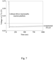
- Example 1 and Comparative Example 1 were subjected to electroplating test at a current density of 0.5 mA / cm 2 to evaluate the cell characteristics when the nanocomposite layer was used in the cell, and the results are shown in Fig. 6 and Fig. 7 , respectively.
- the lithium ions transferred from the lithium metal positive electrode 500 to the copper negative electrode current collector 310, and deposited on the surface of the copper negative electrode current collector 310.
- a significant drop in potential can be observed.
- the silver ions in the nanocomposite layer 200 of the Example 1 can react with the lithium ions at the interface of the negative electrode current collector 310 to form an intermetallic compound.
- the Comparative Example 1 shown in Fig. 7 does not have the nanocomposite layer 200 and therefore no intermetallic reaction occurs at the interface.
- the electroplating process may include ion passage, electrolyte diffusion, charge transfer, atomic surface adsorption, surface diffusion, crystal grain nucleation, and grain growth.
- electrolyte diffusion There is a significant and quantifiable activation energy (at voltage below 0 volts) in grain nucleation and grain growth, which is called overpotential.
- overpotential The smaller the overpotential, the more uniform the electroplating deposited layer is and the more it tends to grow in two dimensions (i.e., a film), while the larger the overpotential, the more it tends to grow in one dimension and the easier it is to form lithium dendrites. Referring to Fig. 6 and Fig.
- Example 1 having the nanocomposite layer 200 can form a thin film with a more uniform thickness, instead of lithium dendrites.
- a nanocomposite layer As described above, according to the embodiments of the present disclosure, there is provided a nanocomposite layer, a method of forming the same, and a battery including the nanocomposite layer.
- the nanocomposite layer is disposed between the negative electrode and the solid-state electrolyte of the battery.
- the nanocomposite layer of the present disclosure is formed by drying a nanocomposite gel containing a carbon nanotube composite material, an organic solvent, a first polymer, a second polymer, and a lithium salt.
- the carbon nanotube composite material includes a surface-modified carbon nanotube with a positively charged group and a plurality of nanoparticles with a negatively charged group.
- the nanoparticles and the surface-modified carbon nanotube are covalently bonded to each other and have a strong attraction therebetween. Therefore, the nanoparticles have good stability under the large discharge rate of the cell, which can prevent the nanoparticles from detaching from the surface-modified carbon nanotubes.
- the nanocomposite layer can effectively improve the lithium ion conductivity, the cycling performance of the cell under large discharge rate, and suppress the formation of lithium dendrites.
Landscapes
- Chemical & Material Sciences (AREA)
- Chemical Kinetics & Catalysis (AREA)
- Electrochemistry (AREA)
- General Chemical & Material Sciences (AREA)
- Engineering & Computer Science (AREA)
- Manufacturing & Machinery (AREA)
- Composite Materials (AREA)
- Materials Engineering (AREA)
- Battery Electrode And Active Subsutance (AREA)
- Secondary Cells (AREA)
- Primary Cells (AREA)
- Carbon And Carbon Compounds (AREA)
Abstract
A nanocomposite layer includes a carbon nanotube composite material and a lithium salt polymer composite. The carbon nanotube composite material includes a surface modified carbon nanotube with a positively charged group and a plurality of nanoparticles with a negatively charged group. The plurality of nanoparticles are attached to the surface modified carbon nanotube. The lithium salt polymer composite wraps the carbon nanotube composite material, and includes a first polymer, a second polymer, and a lithium salt.
Description
- The present invention relates to a nanocomposite layer, a method of forming nanocomposite layer and a battery. More particularly, the nanocomposite layer can be applied to batteries and is disposed on the negative electrode of the battery.
- Lithium-ion batteries have been widely used in electronic devices such as mobile phones and laptops. Currently, lithium-ion batteries are also used in electric vehicles as their power source. A lithium-ion battery is usually composed of a positive electrode, a negative electrode, and an electrolyte. The positive electrode, which is also called as cathode, undergoes a reduction reaction during discharge to reduce conductive ions (e.g., Li+) to uncharged atoms (e.g., Li). The negative electrode, which is also called as anode, undergoes an oxidation reaction during discharge.
- However, there are still many problems to overcome with lithium-ion batteries. For example, the uneven deposition of the lithium ions after repeated charging and discharging causes formation of dendrites on the surface of the negative electrode. The penetration of dendrites through the electrode separator will lead to short circuit and cause safety hazards such as thermal failure and fire of the battery. Therefore, the development direction of lithium-ion battery is to improve the energy density and safety of the battery.
- According to an aspect of the present disclosure, a nanocomposite layer for battery is provided. The nanocomposite layer includes a carbon nanotube composite material and a lithium salt polymer composite. The carbon nanotube composite material includes a surface-modified carbon nanotube with a positively charged group and a plurality of nanoparticles with a negatively charged group, wherein the plurality of nanoparticles is attached to the surface-modified carbon nanotube. The lithium salt polymer composite wraps the carbon nanotube composite material. The lithium salt polymer composite includes a first polymer, a second polymer, and a lithium salt, in which the first polymer is a piezoelectric polymer, the second polymer is a doping molecule that is miscible with the first polymer, and the second polymer is configured to change the crystal structure of the first polymer.
- According to some embodiments of the present disclosure, a surface of the surface-modified carbon nanotube has an amido group.
- According to some embodiments of the present disclosure, the plurality of nanoparticles includes silver nanoparticles, gold nanoparticles, aluminum nanoparticles, aluminum oxide nanoparticles, or combinations thereof.
- According to some embodiments of the present disclosure, the plurality of nanoparticles has an average particle size of about 10 nm to 120 nm.
- According to some embodiments of the present disclosure, the piezoelectric polymer includes polyvinylidene difluoride, polydimethylsiloxane, polyimide, polyvinyl acetate, or combinations thereof, and the doping molecule includes poly(methyl methacrylate) (PMMA), poly(γ-benzyl-L-glutamate), 4,4-oxydiphthalic anhydride, or a ceramic perovskite material in combination with any of the above material.
- According to another aspect of the present disclosure, there is provided a battery including a negative electrode current collector, a negative electrode disposed on the negative electrode current collector, a nanocomposite layer disposed on the negative electrode, a solid-state electrolyte disposed on the nanocomposite layer, a positive electrode disposed on the solid-state electrolyte, and a positive electrode current collector disposed on the positive electrode.
- According to some embodiments of the present disclosure, the nanocomposite layer has a thickness of about 25 microns to 50 microns.
- According to another aspect of the present disclosure, an anode-fee battery is provided. The anode-free battery includes a negative electrode current collector, a nanocomposite layer disposed on the negative electrode current collector, a solid-state electrolyte disposed on the nanocomposite layer, a positive electrode disposed on the solid-state electrolyte, and a positive electrode current collector disposed on the positive electrode.
- According to another aspect of the present disclosure, there is provided a method of forming a nanocomposite layer including mixing a carbon nanotube composite material with an organic solvent, a first polymer, a second polymer, and a lithium salt to form a nanocomposite gel and baking the nanocomposite gel. The carbon nanotube composite material includes a surface-modified carbon nanotube with a positively charged group and a plurality of nanoparticles with a negatively charged group, and the plurality of nanoparticles are attached to the surface-modified carbon nanotube. The first polymer is a piezoelectric polymer, the second polymer is a doping molecule that is miscible with the first polymer, and the second polymer is configured to change the crystal structure of the first polymer.
- According to some embodiments of the present disclosure, the method further includes forming the carbon nanotube composite material, including performing a surface treatment to the carbon nanotube to form the surface-modified carbon nanotube with a positively charged group; mixing the surface-modified carbon nanotube with an aqueous solution of nanoparticles to form a mixture; and drying the mixture.
- According to some embodiments of the present disclosure, the nanocomposite gel includes from about 10 wt% to about 20 wt% of a first polymer, from about 1.5 wt% to about 3 wt% of a second polymer, and from about 5 wt% to about 20 wt% of a lithium salt.
- It is to be understood that both the foregoing general description and the following detailed description are by examples and are intended to provide further explanation of the invention as claimed.
-
-
Fig. 1 is a flowchart illustrating a method of forming a nanocomposite layer according to some embodiments of this disclosure. -
Fig. 2 is a schematic diagram illustrating a carbon nanotube composite material according to some embodiments of this disclosure. -
Fig. 3 is a schematic diagram illustrating the structure a nanocomposite layer according to some embodiments of this disclosure. -
Fig. 4 is a cross-sectional view illustrating a battery according to some embodiments of this disclosure. -
Fig. 5 is a cross-sectional view illustrating an anode-free half-cell having a nanocomposite layer according to one of the examples of this disclosure. -
Fig. 6 is a potential-time curve diagram of an anode-free half-cell having a nanocomposite layer according to one of the examples of this disclosure. -
Fig. 7 is a potential-time curve diagram of an anode-free half-cell without a nanocomposite layer according to a comparative example of this disclosure. -
Fig. 1 is a flowchart illustrating a method of forming a nanocomposite layer according to some embodiments of this disclosure. As shown inFig. 1 , themethod 10 includesoperation 12,operation 14, andoperation 16. - Referring to
Fig. 1 andFig. 2 , inoperation 12 ofmethod 10, a carbon nanotubecomposite material 100 is formed. As shown inFig. 2 , the carbon nanotubecomposite material 100 includes a surface-modifiedcarbon nanotube 102 with a positively charged group and a plurality of thenanoparticles 104 with a negatively charged group, and the plurality of thenanoparticles 104 are attached to the surface-modifiedcarbon nanotube 102. Specifically, the surface-modifiedcarbon nanotube 102 forms covalent bonds with thenanoparticles 104. - In some embodiments, forming the carbon nanotube
composite material 100 may include following operations. First, the carbon nanotube (not shown) is surface-treated to form the surface-modifiedcarbon nanotube 102. In some embodiments, the surface treatment includes a carboxylation, an acyl chlorination, and an amidation of the carbon nanotube. For example, after carboxylation, the carbon nanotube has a -COOH group on its surface after carboxylation. Then, after acyl chlorination, the -COOH group is replaced with -COCI group. Then, after the amidation, the -CI group of the -COCI group of the surface of the nanotube is replaced with -NH(CH2)2-NH3 + group. The nanotube may have a positively charged group on its surface after multi-step functionalization. In some embodiments, the surface of the surface-modifiedcarbon nanotube 102 has an amido group. In some embodiments, the surface-modifiedcarbon nanotube 102 may be directly generated by reacting the carboxylated carbon nanotube with ethylenediamine at high temperature (>350°C) and high pressure (>6MPa). In other embodiments, the carbon nanotube is plasma-treated, for example, with hydrogen-oxygen plasma to generate a -COOH group on the surface of the carbon nanotube, which are then treated with ammonia plasma to generate a positively charged NH3 group. - In some embodiments, the surface-modified
carbon nanotube 102 includes a multi-walled carbon nanotube (MWCNT), a double-walled carbon nanotube (DWCNT), a single-walled carbon nanotube (SWCNT), or combinations thereof. In some embodiments, the surface-modifiedcarbon nanotube 102 has a length of about 5 microns to 15 microns. The carbon nanotube with a length greater than 15 µm is not readily available, while the carbon nanotube with a length less than 5 µm loses continuity and increase in impedance when the resulting nanocomposite layer is subsequently applied to a battery (thenanocomposite layer 200 as shown inFig. 4 ). - Afterwards, the surface-modified
carbon nanotube 102 may be mixed with the aqueous solution ofnanoparticles 104 to form a mixture. In some embodiments, an ultrasonic oscillator may be used to mix the powdered surface-modifiedcarbon nanotube 102 with the aqueous solution ofnanoparticle 104. In some embodiments, thenanoparticles 104 are lithiophilic. In some examples, thenanoparticles 104 include silver nanoparticles, gold nanoparticles, aluminum nanoparticles, aluminum oxide nanoparticles, or combinations thereof. In some embodiments, thenanoparticles 104 are formed by chemical reductions by agents. In some examples, thenanoparticles 104 may be formed by reducing metal ions with a reducing agent. For example, thenanoparticles 104 may be silver citrate nanoparticles as shown inFig. 2 . The surface of the nanoparticles of this structure is slightly negatively charged (5-15 mV). The silver citrate nanoparticles are formed by reducing the silver ions in the aqueous silver nitrate solution with sodium citrate, which form chemical bonds to wrap the citric acid molecules around the silver atomic groups. In other embodiments, sodium citrate can be replaced by sodium borohydride, formate, and sodium hydroxide mixed solution as reducing agents. In some embodiments, the plurality of thenanoparticles 104 has an average particle size of about 10 nm to 120 nm. If the particle size of thenanoparticles 104 is greater than 120nm, thenanoparticles 104 tend to agglomerate during the synthesis process and do not easily attach to the surface-modifiedcarbon nanotubes 102 strongly to form covalent bonds. When the resulting nanocomposite layer is applied to the battery, it will affect the stability of the silver particles during charging and discharging the battery. If the particle size of thenanoparticles 104 is less than 10 nm, it represents that the silver nitrate has not been fully reduced to silver nanoparticles. In some embodiments, the weight ratio of the surface-modifiedcarbon nanotube 102 to the aqueous solution ofnanoparticles 104 is about 1:10 to about 1:20. - The above mixture is then dried. In some embodiments, the mixture may be oven-dried to form a powder. Afterwards, the above powder is dissolved in an organic solvent and then stirred and crushed by an emulsifier to form the carbon
nanotube composite material 100. It should be appreciated that, for ease of understanding, the carbonnanotube composite material 100 shown inFig. 2 is illustrated as negatively chargedsilver citrate nanoparticles 104 attached to the surface of the surface-modifiedcarbon nanotube 102 with a positively charged amido group, but the present invention is not limited thereto. - Referring further to
Fig. 1 , inoperation 14 ofmethod 10, the carbonnanotube composite material 100 is mixed with an organic solvent, a first polymer, a second polymer, and a lithium salt to form a nanocomposite gel. In some embodiments, the carbonnanotube composite material 100 may be mixed with the organic solvent, the first polymer, and the second polymer before mixing with the lithium salt. The nanocomposite gel can be coated on suitable substrate (e.g., the negative electrode of a battery). - In some embodiments, the organic solvent includes N-methyl-2-pyrrolidone (NMP), ethylene carbonate (EC), polycarbonate (PC), dimethyl carbonate (DMC), dimethyl acetamide (DMAC), diethyl carbonate (DEC), or combinations thereof.
- In some embodiments, the first polymer is a piezoelectric polymer that has a high dipole moment and is prone to forming crystals in a chain structure. In some embodiments, the first polymer is a piezoelectric polymer comprising polyvinylidene difluoride (PVDF), polydimethylsiloxane (PDMS), polyimide (PI), polyvinyl acetate (PVA), or combinations thereof. In some embodiments, the nanocomposite gel includes from about 10 wt% to about 20 wt% of the first polymer. When the content of the first polymer is too high, the viscosity of the nanocomposite gel is too low, which affects the subsequent film formation of the resulting nanocomposite layer.
- In some embodiments, the second polymer is a doping molecule that increases the mechanical strength of the first polymer, changes the viscosity of the first polymer, or increases the piezoelectric properties of the first polymer, and is miscible with the first polymer. The crystal structure of the first polymer can be changed by controlling the doping amount and type of the second polymer. In some embodiments, the second polymer is a doping molecule comprising poly(methyl methacrylate) (PMMA), poly(γ-benzyl-L-glutamate), 4,4'-oxydiphthalic anhydride, or a ceramic perovskite material in combination with any of the above material. In some embodiments, the nanocomposite gel includes from about 1.5 wt% to about 3 wt% of the second polymer. When the content of the second polymer is too high, the dipole-dipole force between the second polymer and the first polymer is greater, making viscosity of the nanocomposite gel too high, causing the nanocomposite gel to be difficult to spread, and the resulting coating layer is fragile and loses its protective effect due to excessive stress.
- The first polymer and the second polymer can improve the surface coating of the carbon nanotube, thereby reducing the agglomeration phenomenon. In addition, the first polymer and the second polymer can regulate the viscosity of the nanocomposite gel. Specifically, when the surface-modified
carbon nanotube 102 is covalently bonded with thenanoparticles 104, the overall structure will remain electrically neutral and lose the electric double-layer dispersion characteristics of the surface-modifiedcarbon nanotube 102 due to its positive charge. Therefore, whether the polymer is well coated or not affects the overall dispersion characteristic of the nanocomposite gel. If the dispersion is poor, the viscosity is too low and the resulting nanocomposite layer loses its protective properties. If the viscosity is too high, the nanocomposite gel is difficult to be coated. Therefore, the coating properties of the polymer on the carbonnanotube composite material 100 and the viscosity of the nanocomposite gel have a great influence on the application of the nanocomposite layer. - In some embodiments, the lithium salt includes lithium bis(trifluoromethanesulfonyl)imide (LiTFSI), lithium bis(oxalate)borate (LiBOB), lithium tetrafluoroborate (LiBF4), lithium difluoro(oxalate)borate (LiODFB), lithium bis(fluorosulfonyl)imide (LiFSI), lithium difluorophosphate (LiPO2F2), lithium tetrafluoro(oxalato)phosphate (LiFOP), or combinations thereof. In some embodiments, the nanocomposite gel includes from about 5 wt% to about 20 wt% of the lithium salt. The lithium salt increases the lithium ion conductivity of the nanocomposite gel, aids in lithium ion transport, and allows for a dynamic equilibrium with adjacent metal nanoparticles in intermetallic reaction.
- Referring to
Fig. 1 , inoperation 16 ofmethod 10, the nanocomposite gel is baked. In some embodiments, after the nanocomposite gel is coated on a substrate, the nanocomposite gel is baked at 120 - 150 °C to dry the organic solvent to form thenanocomposite layer 200 shown inFig. 3 . In some embodiments, thenanocomposite layer 200 may be applied to battery. For example, thenanocomposite layer 200 may be formed on a negative electrode of the battery, as described in detail in the subsequentFig. 4 . -
Fig. 3 is a schematic diagram illustrating the structure ofnanocomposite layer 200 according to some embodiments of this disclosure. As shown inFig. 3 , thenanocomposite layer 200 includes the carbonnanotube composite material 100 and the lithiumsalt polymer composite 110. - The carbon
nanotube composite material 100 includes a surface-modifiedcarbon nanotube 102 with a positively charged group and a plurality of thenanoparticles 104 with a negatively charged group, in which a plurality of thenanoparticles 104 are attached to the surface-modifiedcarbon nanotube 102. The carbonnanotube composite material 100 may be any of the carbonnanotube composite material 100 described above, and will not be repeated herein. - The lithium
salt polymer composite 110 wraps the carbonnanotube composite material 100. In some embodiments, the lithiumsalt polymer composite 110 includes a first polymer, a second polymer, and a lithium salt. Specifically, the first polymer and the second polymer as described above may form a complex with the lithium salt. Examples of the first polymer, the second polymer, and the lithium salt may be any of the examples described above, and will not be repeated herein. - Another aspect of this disclosure is a battery.
Fig. 4 is a cross-sectional view illustrating abattery 1000 according to some embodiments of this disclosure. As shown inFig.4 , thebattery 1000 includes a negative electrodecurrent collector 310, anegative electrode 300, ananocomposite layer 200, a solid-state electrolyte 400, apositive electrode 500, and a positive electrodecurrent collector 510. In some embodiments, thebattery 1000 may be a lithium-ion battery. For example, thebattery 1000 may be a lithium cobalt oxide (LCO) battery, a lithium nickel cobalt manganese (NCM) battery, a lithium iron phosphate (LFP) battery, a lithium cobalt binary battery/ternary battery, or the like. - In some embodiments, the negative electrode
current collector 310 may be any suitable material, such as copper foil. Thenegative electrode 300 is disposed on the negative electrodecurrent collector 310. In some embodiments, thenegative electrode 300 includes any suitable material, such as lithium metal, graphite, and silicon-carbon material. In some embodiments, thenegative electrode 300 can be omitted. - The
nanocomposite layer 200 is disposed between thenegative electrode 300 and the solid-state electrolyte 400. Thenanocomposite layer 200 may be formed by drying the aforementioned nanocomposite gel. Thenanocomposite layer 200 includes a carbonnanotube composite material 100 and a lithiumsalt polymer composite 110. Thenanocomposite layer 200 can be any of thenanocomposite layer 200 as described above. In some embodiments, the battery is a battery without negative electrode (i.e., anode-free battery), and thenanocomposite layer 200 is disposed on the negative electrodecurrent collector 310. - The carbon
nanotube composite material 100 includes the surface-modifiedcarbon nanotube 102 with a positively charged group and a plurality of thenanoparticles 104 with a negatively charged group, and the plurality of thenanoparticles 104 are attached to the surface-modifiedcarbon nanotube 102, as shown inFig. 2 . The covalent bond formed between the surface-modifiedcarbon nanotube 102 and thenanoparticles 104 provide a very strong attraction to each other. When the lithium ions are intercalated and disintercalated during charging and discharging of thebattery 1000, themetal nanoparticles 104 are interfused with the lithium ions to form an intermetallic compound, resulting in volume changes. The force between the surface-modifiedcarbon nanotube 102 and themetal nanoparticles 104 can stabilize the metal nanoparticles 104 (e.g., silver particles shown inFig. 2 ), and reduce the silver nanoparticles from detaching from the surface-modifiedcarbon nanotube 102 and agglomerating to become ineffective particles. In addition, the surface-modifiedcarbon nanotube 102 may also improve the conductivity of thenanocomposite layer 200. The carbonnanotube composite material 100 can be used to homogenize the rate and concentration of lithium ions as they transfer between thepositive electrode 500 and thenegative electrode 300. - The lithium
salt polymer composite 110 includes a first polymer, a second polymer, and a lithium salt, as described above. By mixing the lithium ions of the lithium salt with themetal nanoparticles 104, the lithium ions can be induced to from an intermetallic compound with themetal nanoparticles 104 during the transfer at the interface of thenegative electrode 300 to achieve a dynamic equilibrium of the lithium ions. - The
nanocomposite layer 200 formed on thenegative electrode 300 of thebattery 1000 can effectively improve the lithium ion conductivity, the cycling performance of the cell under large discharge rate, and suppress the formation of lithium dendrites. In some embodiments, thenanocomposite layer 200 has a thickness of about 25 µm to about 50 µm. If the thickness of thenanocomposite layer 200 is greater than 50 µm, it will increase the component impedance. If the thickness of thenanocomposite layer 200 is less than 25 µm, it is prone to losing the protective effect on negative electrodes due to uneven coating. - Referring further to
Fig. 4 , the solid-state electrolyte 400 is disposed on thenanocomposite layer 200. In some embodiments, the solid-state electrolyte 400 includes any suitable solid-state electrolyte material. Thepositive electrode 500 is disposed on the solid-state electrolyte 400. In some embodiments, thepositive electrode 500 includes any suitable positive electrode material. The positive electrodecurrent collector 510 is disposed on thepositive electrode 500. In some embodiments, the positive electrodecurrent collector 510 includes any suitable material, such as aluminum foil. - The following examples are intended to detail particular aspects of the present disclosure and to enable those having ordinary skill in the art to implement the present disclosure. However, the following examples should not be used to limit the present disclosure.
-
Fig. 5 is a cross-sectional view illustrating an anode-free half-cell 2000 having a nanocomposite layer according to some embodiments of this disclosure. As shown inFig. 5 , the anode-free half-cell 2000 includes a negative electrode current collector 310 (i.e., anode current collector), ananocomposite layer 200, a separator 400', and a positive electrode 500 (i.e., cathode). - The negative electrode
current collector 310 was a copper foil with a thickness of about 8 µm. Thenanocomposite layer 200 was manufactured by the above method and has a thickness of about 15 µm. Thenanocomposite layer 200 was composed of 0.2 wt% carbon nanotube composite material as shown inFig. 2 and a lithium salt polymer composite containing 11.5 wt% polyvinylidene difluoride, 1.6 wt% poly(methyl methacrylate) and 8.2 %wt lithium bis(trifluoromethanesulfonyl)imide. The separator 400' was from W-Scope Corporation andhad a thickness of about 20 µm. Thepositive electrode 500 was lithium metal with a thickness of about 200 µm. The anode-free half-cell was validated using a liquid electrolyte (not shown in the figure). - The structure of the half-cell of the Comparative Example 1 was similar to the anode-free half-cell 2000 of Example 1, with the difference that the half-cell of the Comparative Example 1 did not have a
nanocomposite layer 200. - The half-cells of Example 1 and Comparative Example 1 were subjected to electroplating test at a current density of 0.5 mA / cm2 to evaluate the cell characteristics when the nanocomposite layer was used in the cell, and the results are shown in
Fig. 6 andFig. 7 , respectively. During electroplating, the lithium ions transferred from the lithium metalpositive electrode 500 to the copper negative electrodecurrent collector 310, and deposited on the surface of the copper negative electrodecurrent collector 310. At this time, a significant drop in potential can be observed. As shown inFig. 6 , the silver ions in thenanocomposite layer 200 of the Example 1 can react with the lithium ions at the interface of the negative electrodecurrent collector 310 to form an intermetallic compound. The Comparative Example 1 shown inFig. 7 does not have thenanocomposite layer 200 and therefore no intermetallic reaction occurs at the interface. - The electroplating process may include ion passage, electrolyte diffusion, charge transfer, atomic surface adsorption, surface diffusion, crystal grain nucleation, and grain growth. There is a significant and quantifiable activation energy (at voltage below 0 volts) in grain nucleation and grain growth, which is called overpotential. The smaller the overpotential, the more uniform the electroplating deposited layer is and the more it tends to grow in two dimensions (i.e., a film), while the larger the overpotential, the more it tends to grow in one dimension and the easier it is to form lithium dendrites. Referring to
Fig. 6 andFig. 7 , the overpotential of Example 1 is about 50 mV and the overpotential of the Comparative Example 1 is about 95 mV. Therefore, Example 1 having thenanocomposite layer 200 can form a thin film with a more uniform thickness, instead of lithium dendrites. - As described above, according to the embodiments of the present disclosure, there is provided a nanocomposite layer, a method of forming the same, and a battery including the nanocomposite layer. The nanocomposite layer is disposed between the negative electrode and the solid-state electrolyte of the battery. The nanocomposite layer of the present disclosure is formed by drying a nanocomposite gel containing a carbon nanotube composite material, an organic solvent, a first polymer, a second polymer, and a lithium salt. The carbon nanotube composite material includes a surface-modified carbon nanotube with a positively charged group and a plurality of nanoparticles with a negatively charged group. The nanoparticles and the surface-modified carbon nanotube are covalently bonded to each other and have a strong attraction therebetween. Therefore, the nanoparticles have good stability under the large discharge rate of the cell, which can prevent the nanoparticles from detaching from the surface-modified carbon nanotubes. In addition, the nanocomposite layer can effectively improve the lithium ion conductivity, the cycling performance of the cell under large discharge rate, and suppress the formation of lithium dendrites.
Claims (11)
- A nanocomposite layer (200) for battery (1000), characterized by comprising:a carbon nanotube composite material (100) comprising a surface-modified carbon nanotube (102) with a positively charged group and a plurality of nanoparticles (104) with a negatively charged group, wherein the plurality of nanoparticles (104) are attached to the surface-modified carbon nanotube (102); anda lithium salt polymer composite (110) wrapping the carbon nanotube composite material (100), wherein the lithium salt polymer composite (110) comprises a first polymer, a second polymer, and a lithium salt, wherein the first polymer is a piezoelectric polymer, the second polymer is a doping molecule that is miscible with the first polymer, and the second polymer is configured to change a crystal structure of the first polymer.
- The nanocomposite layer (200) of claim 1, characterized in that a surface of the surface-modified carbon nanotube (102) has an amido group.
- The nanocomposite layer (200) of any of claims 1-2, characterized in that the plurality of nanoparticles (104) comprises silver nanoparticles, gold nanoparticles, aluminum nanoparticles, aluminum oxide nanoparticles, or combinations thereof.
- The nanocomposite layer (200) of any of claims 1-3, characterized in that the plurality of nanoparticles (104) has an average particle size of about 10 to 120 nm.
- The nanocomposite layer (200) of any of claims 1-4, characterized in that the piezoelectric polymer comprises polyvinylidene difluoride, polydimethylsiloxane, polyimide, polyvinyl acetate, or combinations thereof, and the doping molecule comprises poly(methyl methacrylate) (PMMA), poly(γ-benzyl-L-glutamate),4,4-oxydiphthalic anhydride, or a ceramic perovskite material in combination with any of the above material.
- A battery (1000), characterized by comprising:a negative electrode current collector (310);a negative electrode (300) disposed on the negative electrode current collector (310);the nanocomposite layer (200) of any of claims 1-5 disposed on the negative electrode (300);a solid-state electrolyte (400) disposed on the nanocomposite layer (200);a positive electrode (500) disposed on the solid-state electrolyte (400); anda positive electrode current collector (510) disposed on the positive electrode (500).
- The battery of claim 6, characterized in that the nanocomposite layer (200) has a thickness of about 25 microns to about 50 microns.
- An anode-free battery, characterized by comprising:a negative electrode current collector (310);the nanocomposite layer (200) of any of claims 1-5 disposed on the negative electrode current collector (310);a solid-state electrolyte (400) disposed on the nanocomposite layer (200);a positive electrode (500) disposed on the solid-state electrolyte (400); anda positive electrode current collector (510) disposed on the positive electrode (500).
- A method of forming a nanocomposite layer (200), characterized by comprising:mixing a carbon nanotube composite material (100) with an organic solvent, a first polymer, a second polymer, and a lithium salt to form a nanocomposite gel, wherein the carbon nanotube (100) composite material comprises a surface-modified carbon nanotube (102) with a positively charged group and a plurality of nanoparticles (104) with a negatively charged group, and the plurality of nanoparticles (104) are attached to the surface-modified carbon nanotube (102), wherein the first polymer is a piezoelectric polymer, the second polymer is a doping molecule that is miscible with the first polymer, and the second polymer is configured to change a crystal structure of the first polymer; andbaking the nanocomposite gel.
- The method of claim 9, characterized in that further comprising forming the carbon nanotube composite material (100), which comprises:performing a surface treatment to a carbon nanotube to form the surface-modified carbon nanotube (102) with a positively charged group;mixing the surface-modified carbon nanotube (102) with an aqueous solution of nanoparticles (104) to form a mixture; anddrying the mixture.
- The method of claim 9 or claim 10, characterized in that the nanocomposite gel comprises from about 10 wt% to about 20 wt% of the first polymer, from about 1.5 wt% to about 3 wt% of the second polymer, and from about 5 wt% to about 20 wt% of the lithium salt.
Applications Claiming Priority (1)
| Application Number | Priority Date | Filing Date | Title |
|---|---|---|---|
| TW110137399A TWI785836B (en) | 2021-10-07 | 2021-10-07 | Nanocomposite layer, method of forming nanocomposite layer, and battery |
Publications (1)
| Publication Number | Publication Date |
|---|---|
| EP4163989A1 true EP4163989A1 (en) | 2023-04-12 |
Family
ID=80953438
Family Applications (1)
| Application Number | Title | Priority Date | Filing Date |
|---|---|---|---|
| EP22164608.6A Pending EP4163989A1 (en) | 2021-10-07 | 2022-03-28 | Nanocomposite layer, method of forming nanocomposite layer and battery |
Country Status (4)
| Country | Link |
|---|---|
| US (1) | US20230112508A1 (en) |
| EP (1) | EP4163989A1 (en) |
| CN (1) | CN115954473B (en) |
| TW (1) | TWI785836B (en) |
Families Citing this family (1)
| Publication number | Priority date | Publication date | Assignee | Title |
|---|---|---|---|---|
| WO2025154416A1 (en) * | 2024-01-18 | 2025-07-24 | 株式会社村田製作所 | Negative electrode and lithium-ion secondary battery |
Citations (1)
| Publication number | Priority date | Publication date | Assignee | Title |
|---|---|---|---|---|
| US20190058185A1 (en) * | 2016-08-19 | 2019-02-21 | Lg Chem, Ltd. | Anode comprising multiple protective layers, and lithium secondary battery comprising same |
Family Cites Families (14)
| Publication number | Priority date | Publication date | Assignee | Title |
|---|---|---|---|---|
| CN101712468B (en) * | 2008-09-30 | 2014-08-20 | 清华大学 | Carbon nanotube composite material and preparation method thereof |
| CN102064311B (en) * | 2010-12-08 | 2013-08-21 | 清华大学 | Preparation method of carbon nanometer tube metal particle composite |
| CN105762336B (en) * | 2014-12-19 | 2019-06-25 | 江苏华东锂电技术研究院有限公司 | Anode composite material, preparation method thereof, and lithium ion battery |
| US10084220B2 (en) * | 2016-12-12 | 2018-09-25 | Nanotek Instruments, Inc. | Hybrid solid state electrolyte for lithium secondary battery |
| US11296356B2 (en) * | 2017-04-21 | 2022-04-05 | Showa Denko Materials Co., Ltd. | Polymer electrolyte composition including polymer having a structural unit represented by formula (1), electrolyte salt, and molten salt, and polymer secondary battery including the same |
| KR102093971B1 (en) * | 2017-06-21 | 2020-05-21 | 주식회사 엘지화학 | Lithium secondary battery |
| KR102229452B1 (en) * | 2017-11-08 | 2021-03-17 | 주식회사 엘지화학 | Seperator and lithium sulfur battery comprising the same |
| US10468674B2 (en) * | 2018-01-09 | 2019-11-05 | South Dakota Board Of Regents | Layered high capacity electrodes |
| US10985376B2 (en) * | 2018-06-18 | 2021-04-20 | Global Graphene Group, Inc. | Lithium-sulfur battery containing an electrode-protecting layer |
| CN210668539U (en) * | 2019-07-19 | 2020-06-02 | 湖南工学院 | A lithium-sulfur battery |
| CN111430668A (en) * | 2019-12-31 | 2020-07-17 | 蜂巢能源科技有限公司 | Negative protective layer and preparation method, negative electrode and lithium ion battery |
| US20210218048A1 (en) * | 2020-01-15 | 2021-07-15 | GM Global Technology Operations LLC | Electrode overlaying configuration for batteries comprising bipolar components |
| KR102869518B1 (en) * | 2020-02-18 | 2025-10-10 | 삼성에스디아이 주식회사 | Anode and All Solid secondary battery comprising anode |
| CN113471408B (en) * | 2021-09-06 | 2021-11-19 | 中航锂电科技有限公司 | Method for manufacturing all-solid-state battery composite positive electrode, composite positive electrode and all-solid-state battery |
-
2021
- 2021-10-07 TW TW110137399A patent/TWI785836B/en active
- 2021-11-16 CN CN202111352321.4A patent/CN115954473B/en active Active
-
2022
- 2022-03-10 US US17/691,604 patent/US20230112508A1/en active Pending
- 2022-03-28 EP EP22164608.6A patent/EP4163989A1/en active Pending
Patent Citations (1)
| Publication number | Priority date | Publication date | Assignee | Title |
|---|---|---|---|---|
| US20190058185A1 (en) * | 2016-08-19 | 2019-02-21 | Lg Chem, Ltd. | Anode comprising multiple protective layers, and lithium secondary battery comprising same |
Non-Patent Citations (1)
| Title |
|---|
| FANG K Y ET AL: "Hybridizing CNT/PMMA/PVDF towards high-performance piezoelectric nanofibers", JOURNAL OF PHYSICS D: APPLIED PHYSICS, INSTITUTE OF PHYSICS PUBLISHING, BRISTOL, GB, vol. 51, no. 26, 8 June 2018 (2018-06-08), pages 265305, XP020328563, ISSN: 0022-3727, [retrieved on 20180608], DOI: 10.1088/1361-6463/AAC600 * |
Also Published As
| Publication number | Publication date |
|---|---|
| TWI785836B (en) | 2022-12-01 |
| CN115954473A (en) | 2023-04-11 |
| CN115954473B (en) | 2026-03-31 |
| US20230112508A1 (en) | 2023-04-13 |
| TW202316702A (en) | 2023-04-16 |
Similar Documents
| Publication | Publication Date | Title |
|---|---|---|
| EP4411880A1 (en) | Positive electrode sheet, lithium-ion secondary battery, battery module, battery pack, and electrical apparatus | |
| US9843045B2 (en) | Negative electrode active material and method for producing the same | |
| EP3457474B1 (en) | Sulfur-carbon composite, preparation method therefor, and lithium-sulfur battery comprising same | |
| EP3401981B1 (en) | Electrode for energy storage devices | |
| CN102598388B (en) | Lithium secondary battery | |
| KR100896556B1 (en) | Positive electrode material for lithium secondary cell | |
| CN107431199B (en) | Positive electrode active material and positive electrode including metal nanoparticles, and lithium-sulfur battery including the same | |
| EP2908370B1 (en) | Low resistance electrode for electrochemical element, method for manufacturing same, and electrochemical element including same | |
| JP5838934B2 (en) | Method for producing positive electrode active material for non-aqueous electrolyte secondary battery | |
| EP3637513A1 (en) | Composite-coated nano-tin negative electrode material, preparation method therefor and use thereof | |
| CN107710463A (en) | Positive electrode for lithium-sulfur battery, manufacturing method thereof, and lithium-sulfur battery comprising same | |
| KR101994912B1 (en) | Electrode active material slurry and secondary battery comprising the same | |
| CN110911644A (en) | A kind of lithium ion positive electrode coating and lithium ion battery | |
| EP4261936B1 (en) | Negative electrode and secondary battery including the same | |
| JP2023048950A (en) | High capacity lithium ion secondary battery | |
| CN115842118A (en) | Lithium salt composite material, negative plate, preparation method of negative plate, battery and electricity utilization device | |
| CN104781967A (en) | Active material particles, positive electrode for electricity storage device, electricity storage device, and method for producing active material particles | |
| JP2021533551A (en) | Positive electrode active material for lithium secondary battery, its manufacturing method and lithium secondary battery containing it | |
| EP4163989A1 (en) | Nanocomposite layer, method of forming nanocomposite layer and battery | |
| US20180175385A1 (en) | Graphene-Vanadium Oxide Nanowire, Method for Preparation Thereof, Positive Active Material Comprising the Same and Lithium Battery Comprising the Positive Active Material | |
| JP2011181387A (en) | Manufacturing method of electrode mixture for electrochemical element | |
| KR20240131270A (en) | Carbon nanotube dispersed solution and method for preparing the same | |
| KR20240131269A (en) | Carbon nanotube dispersed solution and method for preparing the same | |
| EP4231376A1 (en) | All-solid-state lithium secondary battery and method for manufacturing same | |
| CN115133015A (en) | Lithium ion secondary battery |
Legal Events
| Date | Code | Title | Description |
|---|---|---|---|
| PUAI | Public reference made under article 153(3) epc to a published international application that has entered the european phase |
Free format text: ORIGINAL CODE: 0009012 |
|
| STAA | Information on the status of an ep patent application or granted ep patent |
Free format text: STATUS: REQUEST FOR EXAMINATION WAS MADE |
|
| 17P | Request for examination filed |
Effective date: 20220328 |
|
| AK | Designated contracting states |
Kind code of ref document: A1 Designated state(s): AL AT BE BG CH CY CZ DE DK EE ES FI FR GB GR HR HU IE IS IT LI LT LU LV MC MK MT NL NO PL PT RO RS SE SI SK SM TR |