EP4163947A1 - Fuse device, inflatable ring network cabinet and environment-friendly switch cabinet including same - Google Patents
Fuse device, inflatable ring network cabinet and environment-friendly switch cabinet including same Download PDFInfo
- Publication number
- EP4163947A1 EP4163947A1 EP22306382.7A EP22306382A EP4163947A1 EP 4163947 A1 EP4163947 A1 EP 4163947A1 EP 22306382 A EP22306382 A EP 22306382A EP 4163947 A1 EP4163947 A1 EP 4163947A1
- Authority
- EP
- European Patent Office
- Prior art keywords
- fuse
- guiding element
- fuse device
- threaded hole
- electrode
- Prior art date
- Legal status (The legal status is an assumption and is not a legal conclusion. Google has not performed a legal analysis and makes no representation as to the accuracy of the status listed.)
- Granted
Links
Images

Classifications
-
- H—ELECTRICITY
- H01—ELECTRIC ELEMENTS
- H01H—ELECTRIC SWITCHES; RELAYS; SELECTORS; EMERGENCY PROTECTIVE DEVICES
- H01H85/00—Protective devices in which the current flows through a part of fusible material and this current is interrupted by displacement of the fusible material when this current becomes excessive
- H01H85/02—Details
- H01H85/20—Bases for supporting the fuse; Separate parts thereof
- H01H85/205—Electric connections to contacts on the base
-
- H—ELECTRICITY
- H01—ELECTRIC ELEMENTS
- H01H—ELECTRIC SWITCHES; RELAYS; SELECTORS; EMERGENCY PROTECTIVE DEVICES
- H01H85/00—Protective devices in which the current flows through a part of fusible material and this current is interrupted by displacement of the fusible material when this current becomes excessive
- H01H85/02—Details
- H01H85/20—Bases for supporting the fuse; Separate parts thereof
- H01H2085/2065—Bases for supporting the fuse; Separate parts thereof with base contacts adapted or adaptable to fuses of different lenghts; bases with self-aligning contacts; intermediate adaptation pieces
-
- H—ELECTRICITY
- H01—ELECTRIC ELEMENTS
- H01H—ELECTRIC SWITCHES; RELAYS; SELECTORS; EMERGENCY PROTECTIVE DEVICES
- H01H85/00—Protective devices in which the current flows through a part of fusible material and this current is interrupted by displacement of the fusible material when this current becomes excessive
- H01H85/02—Details
- H01H85/20—Bases for supporting the fuse; Separate parts thereof
- H01H85/202—Bases for supporting the fuse; Separate parts thereof for fuses with ferrule type end contacts
Definitions
- the present application relates to a fuse device.
- the present application can be not exclusively applied to a fuse unit of an inflatable ring network cabinet and a fuse unit of an environment-friendly switch cabinet. Therefore, the present application also relates to an inflatable ring network cabinet including the fuse device and an environment-friendly switch cabinet including the fuse device.
- a fuse guiding element In a fully insulated fuse tube cabin, in order to facilitate mounting a fuse, a fuse guiding element should be added, which helps to avoid damaging a plum blossom finger during the mounting process of the fuse, and the plum blossom finger is used to ensure a good electrical connection of the fuse.
- Most of the existing schemes fixedly mount the plum-blossom contact finger in a bottom electrode of the fuse tube cabin, and the guiding element is cast in the fuse tube cabin, which is very inconvenient when replacing these two components, so that the fuse tube cabin can only be applied to a fixed fuse, which limits the adaptability of the fuse tube cabin to different fuses, and lacks flexible measures for using fuses with different plug-in sizes.
- the present application relates to a fuse device, which can solve the problem that the guiding element and the plum-blossom contact finger in the fuse tube cabin are not easy to maintain and replace, and can make the fuse tube cabin suitable for more fuses with different plug-in size requirements.
- the present application provides a fuse device, which includes a fuse; a fuse tube cabin for accommodating the fuse; a guiding element, removably mounted to an electrode in the fuse tube cabin, for guiding the fuse upon the fuse being inserted into the fuse tube cabin.
- the fuse device further includes a plurality of contact fingers which are removably mounted to the guiding element and extend axially towards the electrode.
- the guiding element is removably mounted to the electrode by a first fastener.
- the guiding element includes a first threaded hole
- the electrode includes a corresponding threaded hole
- the first fastener is a screw which is screwed into the first threaded hole and the corresponding threaded hole to removably mount the guiding element to the electrode.
- the plurality of contact fingers are removably mounted to the guiding element by a second fastener.
- each of the plurality of contact fingers includes a second threaded hole
- the guiding element includes a corresponding threaded hole
- the second fastener is a screw screwed into the second threaded hole and the corresponding threaded hole to removably mount the plurality of contact fingers to the guiding element.
- the guiding element is a metal guiding element or a semiconductor guiding element.
- the present application also provides an inflatable ring net cabinet, which includes the above-mentioned fuse device.
- the present application also provides an environment-friendly switch cabinet, which includes the above-mentioned fuse device.
- the fuse device 1 includes a fuse, a fuse tube cabin 11 for accommodating the fuse, and a guiding element 12.
- the guiding element is made of a metal material or a semiconductor material, and the electrode 13 is arranged at the bottom of the fuse tube cabin 11.
- the structure of the fuse is not important to the present application, so it is not described in the specification and drawings, and those skilled in the art will understand the structure of the fuse.
- the guiding element 12 is mounted in the fuse tube cabin 11 and is used to guide the fuse upon the fuse being inserted into the fuse tube cabin 11, so as to facilitate mounting the fuse and prevent the contact fingers 14 of the fuse device 1 from being damaged during the mounting process.
- the guiding element 12 is removably mounted to the electrode 13, for example, by a first fastener 15.
- the first fastener 15 may be a screw.
- the guiding element 12 includes a first threaded hole 121 (as shown in FIG. 3 ), and the electrode 13 includes a corresponding threaded hole. The screw is screwed into the first threaded hole and the corresponding threaded hole to removably mount the guiding element 12 to the electrode 13.
- a plurality of contact fingers 14 are removably mounted to the guiding element 12, and extend in the axial direction X (as shown in FIG. 2 ) toward the electrode 13.
- the plurality of contact fingers can be removably mounted to a bottom surface 122 (the surface facing the electrode 13) of the guiding element by a second fastener 16 (such as a screw), as shown in FIG. 4 .
- each of the plurality of contact fingers includes a second threaded hole
- the guiding element includes a corresponding threaded hole
- screws are screwed into the second threaded holes and the corresponding threaded holes to removably mount the plurality of contact fingers to the guiding element.
- the guiding element By removably mounting the guiding element to the electrode and the plurality of contact fingers to the guiding element, the guiding element, the plurality of contact fingers and the fuse have good continuity of energization during the operation of the fuse device, and at the same time, when the electrical connection needs to be disassembled, only the guiding element is detached, and the guiding element and the contact fingers can be easily replaced and maintained, so that the same fuse tube cabin can adapt to more fuses with different sizes.
- the present application is not exclusively used in inflatable ring network cabinets and environment-friendly switch cabinets.
Landscapes
- Fuses (AREA)
Abstract
Description
- The present application relates to a fuse device. The present application can be not exclusively applied to a fuse unit of an inflatable ring network cabinet and a fuse unit of an environment-friendly switch cabinet. Therefore, the present application also relates to an inflatable ring network cabinet including the fuse device and an environment-friendly switch cabinet including the fuse device.
- In a fully insulated fuse tube cabin, in order to facilitate mounting a fuse, a fuse guiding element should be added, which helps to avoid damaging a plum blossom finger during the mounting process of the fuse, and the plum blossom finger is used to ensure a good electrical connection of the fuse. Most of the existing schemes fixedly mount the plum-blossom contact finger in a bottom electrode of the fuse tube cabin, and the guiding element is cast in the fuse tube cabin, which is very inconvenient when replacing these two components, so that the fuse tube cabin can only be applied to a fixed fuse, which limits the adaptability of the fuse tube cabin to different fuses, and lacks flexible measures for using fuses with different plug-in sizes.
- Therefore, the present application relates to a fuse device, which can solve the problem that the guiding element and the plum-blossom contact finger in the fuse tube cabin are not easy to maintain and replace, and can make the fuse tube cabin suitable for more fuses with different plug-in size requirements.
- The present application provides a fuse device, which includes a fuse; a fuse tube cabin for accommodating the fuse; a guiding element, removably mounted to an electrode in the fuse tube cabin, for guiding the fuse upon the fuse being inserted into the fuse tube cabin.
- Advantageously, the fuse device further includes a plurality of contact fingers which are removably mounted to the guiding element and extend axially towards the electrode.
- Advantageously, the guiding element is removably mounted to the electrode by a first fastener.
- Advantageously, the guiding element includes a first threaded hole, the electrode includes a corresponding threaded hole, and the first fastener is a screw which is screwed into the first threaded hole and the corresponding threaded hole to removably mount the guiding element to the electrode.
- Advantageously, the plurality of contact fingers are removably mounted to the guiding element by a second fastener.
- Advantageously, each of the plurality of contact fingers includes a second threaded hole, the guiding element includes a corresponding threaded hole, and the second fastener is a screw screwed into the second threaded hole and the corresponding threaded hole to removably mount the plurality of contact fingers to the guiding element.
- Advantageously, the guiding element is a metal guiding element or a semiconductor guiding element.
- The present application also provides an inflatable ring net cabinet, which includes the above-mentioned fuse device.
- The present application also provides an environment-friendly switch cabinet, which includes the above-mentioned fuse device.
- The advantages and objectives of the present application can be better understood in the following preferred embodiments of the present application described in detail with the accompanying drawings. In order to better show the relationship of the components in the drawings, the drawings are not drawn to scale. In the accompanying drawings:
-
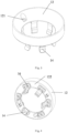
Fig. 1 shows a perspective view of a fuse device according to the present application, and the fuse is not shown for clarity; -
Fig. 2 shows an axial sectional view of the fuse device according to the present application, and the fuse is not shown for clarity; -
Fig. 3 shows a perspective view of a guiding element and a plurality of contact fingers, which are mounted together, of a fuse device according to the present application; and -
Fig. 4 shows another perspective view of the guiding element and a plurality of contact fingers, which are mounted together, of a fuse device according to the present application. - Various embodiments according to the present application will be described in detail with reference to the drawings. Herein, it should be noted that, in the drawings, the same reference numerals are given to components that basically have the same or similar structures and functions, and repeated descriptions about them will be omitted. The term "including A, B, C, etc. in turn" only indicates the arrangement order of included components A, B, C, etc., and does not exclude the possibility of including other components between A and B and/or between B and C.
- The drawings in this specification are schematic diagrams, which assist in explaining the conception of the present application and schematically show the shapes of various parts and their relationships.
- Hereinafter, the preferred embodiments of the present application are described in detail with reference to
Figs. 1 to 4 . - As shown in
Figs. 1 and 2 , thefuse device 1 according to the present application includes a fuse, afuse tube cabin 11 for accommodating the fuse, and a guidingelement 12. The guiding element is made of a metal material or a semiconductor material, and theelectrode 13 is arranged at the bottom of thefuse tube cabin 11. The structure of the fuse is not important to the present application, so it is not described in the specification and drawings, and those skilled in the art will understand the structure of the fuse. - The guiding
element 12 is mounted in thefuse tube cabin 11 and is used to guide the fuse upon the fuse being inserted into thefuse tube cabin 11, so as to facilitate mounting the fuse and prevent thecontact fingers 14 of thefuse device 1 from being damaged during the mounting process. - The guiding
element 12 is removably mounted to theelectrode 13, for example, by afirst fastener 15. For example, thefirst fastener 15 may be a screw. In this case, the guidingelement 12 includes a first threaded hole 121 (as shown inFIG. 3 ), and theelectrode 13 includes a corresponding threaded hole. The screw is screwed into the first threaded hole and the corresponding threaded hole to removably mount the guidingelement 12 to theelectrode 13. - A plurality of
contact fingers 14 are removably mounted to the guidingelement 12, and extend in the axial direction X (as shown inFIG. 2 ) toward theelectrode 13. For example, the plurality of contact fingers can be removably mounted to a bottom surface 122 (the surface facing the electrode 13) of the guiding element by a second fastener 16 (such as a screw), as shown inFIG. 4 . In this case, although not explicitly shown in the drawings, each of the plurality of contact fingers includes a second threaded hole, the guiding element includes a corresponding threaded hole, and screws are screwed into the second threaded holes and the corresponding threaded holes to removably mount the plurality of contact fingers to the guiding element. - The above screw is used as an example to describe the removable mounting of the guiding element to the electrode and the removable mounting of the plurality of contact fingers to the guiding element, but those skilled in the art should understand that such removable mounting can be realized by any other means.
- By removably mounting the guiding element to the electrode and the plurality of contact fingers to the guiding element, the guiding element, the plurality of contact fingers and the fuse have good continuity of energization during the operation of the fuse device, and at the same time, when the electrical connection needs to be disassembled, only the guiding element is detached, and the guiding element and the contact fingers can be easily replaced and maintained, so that the same fuse tube cabin can adapt to more fuses with different sizes.
- In addition, the present application is not exclusively used in inflatable ring network cabinets and environment-friendly switch cabinets.
- The above description is only an explanation of the present application, so that ordinary skilled in the art can implement the scheme completely, but it is not a limitation to the present application. The above disclosed technical features are not limited to the disclosed combination with other features, and the ordinary skilled in the art can also make other combinations among the technical features according to the purpose of the present application, so as to realize the purpose of the present application.
Claims (9)
- A fuse device, which is characterized by comprising:a fuse;a fuse tube cabin for accommodating the fuse;a guiding element, removably mounted to an electrode in the fuse tube cabin, for guiding the fuse upon the fuse being inserted into the fuse tube cabin.
- The fuse device according to claim 1, which is characterized in that, the fuse device further comprises a plurality of contact fingers, and the plurality of contact fingers are removably mounted to the guiding element and extend axially toward the electrode.
- The fuse device according to claim 1, which is characterized in that, the guiding element is removably mounted to the electrode by a first fastener.
- The fuse device according to claim 3, which is characterized in that, the guiding element comprises a first threaded hole, the electrode includes a corresponding threaded hole, and the first fastener is a screw, which is screwed into the first threaded hole and the corresponding threaded hole to removably mount the guiding element to the electrode.
- The fuse device according to claim 2, which is characterized in that, the plurality of contact fingers are removably mounted to the guiding element by a second fastener.
- The fuse device according to claim 5, which is characterized in that, each of the plurality of contact fingers comprises a second threaded hole, the guiding element includes a corresponding threaded hole, and the second fastener is a screw, which is screwed into the second threaded hole and the corresponding threaded hole to removably mount the plurality of contact fingers to the guiding element.
- The fuse device according to claim 1, which is characterized in that, the guiding element is a metal guiding element or a semiconductor guiding element.
- An inflatable ring network cabinet, which is characterized by comprising the fuse device according to any one of claims 1 to 7.
- An environment-friendly switch cabinet, which is characterized by comprising the fuse device according to any one of claims 1 to 7.
Applications Claiming Priority (1)
| Application Number | Priority Date | Filing Date | Title |
|---|---|---|---|
| CN202122439484.8U CN216121215U (en) | 2021-10-11 | 2021-10-11 | Fuse device, inflatable ring main unit comprising same and environment-friendly switch cabinet |
Publications (3)
| Publication Number | Publication Date |
|---|---|
| EP4163947A1 true EP4163947A1 (en) | 2023-04-12 |
| EP4163947C0 EP4163947C0 (en) | 2024-08-21 |
| EP4163947B1 EP4163947B1 (en) | 2024-08-21 |
Family
ID=80691701
Family Applications (1)
| Application Number | Title | Priority Date | Filing Date |
|---|---|---|---|
| EP22306382.7A Active EP4163947B1 (en) | 2021-10-11 | 2022-09-21 | Fuse device, inflatable ring network cabinet and environment-friendly switch cabinet including same |
Country Status (2)
| Country | Link |
|---|---|
| EP (1) | EP4163947B1 (en) |
| CN (1) | CN216121215U (en) |
Citations (2)
| Publication number | Priority date | Publication date | Assignee | Title |
|---|---|---|---|---|
| EP2503585A1 (en) * | 2011-03-21 | 2012-09-26 | DRIBO, spol. s.r.o. | An extender for placement of a roller fuse in contact of current conductive path of electric switching and/or fuse device of high or very high voltage |
| CN209328836U (en) * | 2019-02-25 | 2019-08-30 | 施耐德电器工业公司 | Fuse apparatus, the Inflatable ring main unit including it and environment-friendly type switchgear |
-
2021
- 2021-10-11 CN CN202122439484.8U patent/CN216121215U/en active Active
-
2022
- 2022-09-21 EP EP22306382.7A patent/EP4163947B1/en active Active
Patent Citations (2)
| Publication number | Priority date | Publication date | Assignee | Title |
|---|---|---|---|---|
| EP2503585A1 (en) * | 2011-03-21 | 2012-09-26 | DRIBO, spol. s.r.o. | An extender for placement of a roller fuse in contact of current conductive path of electric switching and/or fuse device of high or very high voltage |
| CN209328836U (en) * | 2019-02-25 | 2019-08-30 | 施耐德电器工业公司 | Fuse apparatus, the Inflatable ring main unit including it and environment-friendly type switchgear |
Also Published As
| Publication number | Publication date |
|---|---|
| EP4163947C0 (en) | 2024-08-21 |
| EP4163947B1 (en) | 2024-08-21 |
| CN216121215U (en) | 2022-03-22 |
Similar Documents
| Publication | Publication Date | Title |
|---|---|---|
| TW503420B (en) | A three-position electrical switch having a switching element that is movable in axial translation | |
| AU8291087A (en) | Switch-mode power supply protective circuit arrangement | |
| US20130111098A1 (en) | Power supply unit and power supply system for servers | |
| US20190056770A1 (en) | Atx power supply and housing thereof | |
| JP6563160B1 (en) | Busbar connection device | |
| EP4163947B1 (en) | Fuse device, inflatable ring network cabinet and environment-friendly switch cabinet including same | |
| US6867972B2 (en) | Power component assembly for mechatronic integration of power components | |
| CN113346383A (en) | Novel distribution box structure | |
| CN210837635U (en) | Fuse device and high-voltage contactor | |
| US2566425A (en) | Strip terminal connector | |
| GB534767A (en) | Improvements in or relating to piezo electric crystal mountings | |
| CN108597915B (en) | A high current conducting structure | |
| CN111192786B (en) | Side-placing pole | |
| CN213602237U (en) | Integrated control cabinet | |
| CN215870777U (en) | Compensation device and electric device | |
| CN210272218U (en) | Dual-power supply switching power supply equipment | |
| CN212648876U (en) | A inlet wire case for distribution control equipment | |
| CN209806264U (en) | Packaging box for electronic device | |
| CN210052650U (en) | Voltage-sharing cover and switch assembly comprising same | |
| JP6137280B2 (en) | Power converter | |
| CN217281715U (en) | Adjustable separation mechanism of low-voltage switch cabinet | |
| CN211063086U (en) | Module breakdown-preventing intelligent switch cabinet with static dispersing structure | |
| CN110047710A (en) | A kind of card slot type breaker of plastic casing | |
| US3035210A (en) | Flyback transformer mountings | |
| CN220382364U (en) | Safety socket |
Legal Events
| Date | Code | Title | Description |
|---|---|---|---|
| PUAI | Public reference made under article 153(3) epc to a published international application that has entered the european phase |
Free format text: ORIGINAL CODE: 0009012 |
|
| STAA | Information on the status of an ep patent application or granted ep patent |
Free format text: STATUS: THE APPLICATION HAS BEEN PUBLISHED |
|
| AK | Designated contracting states |
Kind code of ref document: A1 Designated state(s): AL AT BE BG CH CY CZ DE DK EE ES FI FR GB GR HR HU IE IS IT LI LT LU LV MC MK MT NL NO PL PT RO RS SE SI SK SM TR |
|
| STAA | Information on the status of an ep patent application or granted ep patent |
Free format text: STATUS: REQUEST FOR EXAMINATION WAS MADE |
|
| 17P | Request for examination filed |
Effective date: 20230922 |
|
| RBV | Designated contracting states (corrected) |
Designated state(s): AL AT BE BG CH CY CZ DE DK EE ES FI FR GB GR HR HU IE IS IT LI LT LU LV MC MK MT NL NO PL PT RO RS SE SI SK SM TR |
|
| GRAP | Despatch of communication of intention to grant a patent |
Free format text: ORIGINAL CODE: EPIDOSNIGR1 |
|
| STAA | Information on the status of an ep patent application or granted ep patent |
Free format text: STATUS: GRANT OF PATENT IS INTENDED |
|
| INTG | Intention to grant announced |
Effective date: 20240412 |
|
| GRAS | Grant fee paid |
Free format text: ORIGINAL CODE: EPIDOSNIGR3 |
|
| GRAA | (expected) grant |
Free format text: ORIGINAL CODE: 0009210 |
|
| STAA | Information on the status of an ep patent application or granted ep patent |
Free format text: STATUS: THE PATENT HAS BEEN GRANTED |
|
| AK | Designated contracting states |
Kind code of ref document: B1 Designated state(s): AL AT BE BG CH CY CZ DE DK EE ES FI FR GB GR HR HU IE IS IT LI LT LU LV MC MK MT NL NO PL PT RO RS SE SI SK SM TR |
|
| REG | Reference to a national code |
Ref country code: GB Ref legal event code: FG4D |
|
| REG | Reference to a national code |
Ref country code: CH Ref legal event code: EP |
|
| REG | Reference to a national code |
Ref country code: DE Ref legal event code: R096 Ref document number: 602022005501 Country of ref document: DE |
|
| REG | Reference to a national code |
Ref country code: IE Ref legal event code: FG4D |
|
| U01 | Request for unitary effect filed |
Effective date: 20240821 |
|
| U07 | Unitary effect registered |
Designated state(s): AT BE BG DE DK EE FI FR IT LT LU LV MT NL PT RO SE SI Effective date: 20240902 |
|
| U20 | Renewal fee for the european patent with unitary effect paid |
Year of fee payment: 3 Effective date: 20240926 |
|
| PG25 | Lapsed in a contracting state [announced via postgrant information from national office to epo] |
Ref country code: NO Free format text: LAPSE BECAUSE OF FAILURE TO SUBMIT A TRANSLATION OF THE DESCRIPTION OR TO PAY THE FEE WITHIN THE PRESCRIBED TIME-LIMIT Effective date: 20241121 |
|
| PG25 | Lapsed in a contracting state [announced via postgrant information from national office to epo] |
Ref country code: PL Free format text: LAPSE BECAUSE OF FAILURE TO SUBMIT A TRANSLATION OF THE DESCRIPTION OR TO PAY THE FEE WITHIN THE PRESCRIBED TIME-LIMIT Effective date: 20240821 Ref country code: GR Free format text: LAPSE BECAUSE OF FAILURE TO SUBMIT A TRANSLATION OF THE DESCRIPTION OR TO PAY THE FEE WITHIN THE PRESCRIBED TIME-LIMIT Effective date: 20241122 |
|
| PG25 | Lapsed in a contracting state [announced via postgrant information from national office to epo] |
Ref country code: IS Free format text: LAPSE BECAUSE OF FAILURE TO SUBMIT A TRANSLATION OF THE DESCRIPTION OR TO PAY THE FEE WITHIN THE PRESCRIBED TIME-LIMIT Effective date: 20241221 |
|
| PG25 | Lapsed in a contracting state [announced via postgrant information from national office to epo] |
Ref country code: HR Free format text: LAPSE BECAUSE OF FAILURE TO SUBMIT A TRANSLATION OF THE DESCRIPTION OR TO PAY THE FEE WITHIN THE PRESCRIBED TIME-LIMIT Effective date: 20240821 |
|
| PG25 | Lapsed in a contracting state [announced via postgrant information from national office to epo] |
Ref country code: RS Free format text: LAPSE BECAUSE OF FAILURE TO SUBMIT A TRANSLATION OF THE DESCRIPTION OR TO PAY THE FEE WITHIN THE PRESCRIBED TIME-LIMIT Effective date: 20241121 Ref country code: ES Free format text: LAPSE BECAUSE OF FAILURE TO SUBMIT A TRANSLATION OF THE DESCRIPTION OR TO PAY THE FEE WITHIN THE PRESCRIBED TIME-LIMIT Effective date: 20240821 |
|
| PG25 | Lapsed in a contracting state [announced via postgrant information from national office to epo] |
Ref country code: RS Free format text: LAPSE BECAUSE OF FAILURE TO SUBMIT A TRANSLATION OF THE DESCRIPTION OR TO PAY THE FEE WITHIN THE PRESCRIBED TIME-LIMIT Effective date: 20241121 Ref country code: PL Free format text: LAPSE BECAUSE OF FAILURE TO SUBMIT A TRANSLATION OF THE DESCRIPTION OR TO PAY THE FEE WITHIN THE PRESCRIBED TIME-LIMIT Effective date: 20240821 Ref country code: NO Free format text: LAPSE BECAUSE OF FAILURE TO SUBMIT A TRANSLATION OF THE DESCRIPTION OR TO PAY THE FEE WITHIN THE PRESCRIBED TIME-LIMIT Effective date: 20241121 Ref country code: IS Free format text: LAPSE BECAUSE OF FAILURE TO SUBMIT A TRANSLATION OF THE DESCRIPTION OR TO PAY THE FEE WITHIN THE PRESCRIBED TIME-LIMIT Effective date: 20241221 Ref country code: HR Free format text: LAPSE BECAUSE OF FAILURE TO SUBMIT A TRANSLATION OF THE DESCRIPTION OR TO PAY THE FEE WITHIN THE PRESCRIBED TIME-LIMIT Effective date: 20240821 Ref country code: GR Free format text: LAPSE BECAUSE OF FAILURE TO SUBMIT A TRANSLATION OF THE DESCRIPTION OR TO PAY THE FEE WITHIN THE PRESCRIBED TIME-LIMIT Effective date: 20241122 Ref country code: ES Free format text: LAPSE BECAUSE OF FAILURE TO SUBMIT A TRANSLATION OF THE DESCRIPTION OR TO PAY THE FEE WITHIN THE PRESCRIBED TIME-LIMIT Effective date: 20240821 |
|
| PG25 | Lapsed in a contracting state [announced via postgrant information from national office to epo] |
Ref country code: SM Free format text: LAPSE BECAUSE OF FAILURE TO SUBMIT A TRANSLATION OF THE DESCRIPTION OR TO PAY THE FEE WITHIN THE PRESCRIBED TIME-LIMIT Effective date: 20240821 |
|
| PG25 | Lapsed in a contracting state [announced via postgrant information from national office to epo] |
Ref country code: CZ Free format text: LAPSE BECAUSE OF FAILURE TO SUBMIT A TRANSLATION OF THE DESCRIPTION OR TO PAY THE FEE WITHIN THE PRESCRIBED TIME-LIMIT Effective date: 20240821 |
|
| PG25 | Lapsed in a contracting state [announced via postgrant information from national office to epo] |
Ref country code: SK Free format text: LAPSE BECAUSE OF FAILURE TO SUBMIT A TRANSLATION OF THE DESCRIPTION OR TO PAY THE FEE WITHIN THE PRESCRIBED TIME-LIMIT Effective date: 20240821 |
|
| PLBE | No opposition filed within time limit |
Free format text: ORIGINAL CODE: 0009261 |
|
| STAA | Information on the status of an ep patent application or granted ep patent |
Free format text: STATUS: NO OPPOSITION FILED WITHIN TIME LIMIT |
|
| PG25 | Lapsed in a contracting state [announced via postgrant information from national office to epo] |
Ref country code: MC Free format text: LAPSE BECAUSE OF FAILURE TO SUBMIT A TRANSLATION OF THE DESCRIPTION OR TO PAY THE FEE WITHIN THE PRESCRIBED TIME-LIMIT Effective date: 20240821 |
|
| PG25 | Lapsed in a contracting state [announced via postgrant information from national office to epo] |
Ref country code: IE Free format text: LAPSE BECAUSE OF NON-PAYMENT OF DUE FEES Effective date: 20240921 |
|
| 26N | No opposition filed |
Effective date: 20250522 |
|
| U20 | Renewal fee for the european patent with unitary effect paid |
Year of fee payment: 4 Effective date: 20250925 |
|
| PG25 | Lapsed in a contracting state [announced via postgrant information from national office to epo] |
Ref country code: CY Free format text: LAPSE BECAUSE OF FAILURE TO SUBMIT A TRANSLATION OF THE DESCRIPTION OR TO PAY THE FEE WITHIN THE PRESCRIBED TIME-LIMIT; INVALID AB INITIO Effective date: 20220921 |
|
| PG25 | Lapsed in a contracting state [announced via postgrant information from national office to epo] |
Ref country code: HU Free format text: LAPSE BECAUSE OF FAILURE TO SUBMIT A TRANSLATION OF THE DESCRIPTION OR TO PAY THE FEE WITHIN THE PRESCRIBED TIME-LIMIT; INVALID AB INITIO Effective date: 20220921 |
|
| REG | Reference to a national code |
Ref country code: CH Ref legal event code: H13 Free format text: ST27 STATUS EVENT CODE: U-0-0-H10-H13 (AS PROVIDED BY THE NATIONAL OFFICE) Effective date: 20260504 |