EP4163877A1 - Information processing device, display range determination method, and program - Google Patents
Information processing device, display range determination method, and program Download PDFInfo
- Publication number
- EP4163877A1 EP4163877A1 EP21829743.0A EP21829743A EP4163877A1 EP 4163877 A1 EP4163877 A1 EP 4163877A1 EP 21829743 A EP21829743 A EP 21829743A EP 4163877 A1 EP4163877 A1 EP 4163877A1
- Authority
- EP
- European Patent Office
- Prior art keywords
- viewpoint
- display
- information
- switching
- line
- Prior art date
- Legal status (The legal status is an assumption and is not a legal conclusion. Google has not performed a legal analysis and makes no representation as to the accuracy of the status listed.)
- Pending
Links
Images





Classifications
-
- H—ELECTRICITY
- H04—ELECTRIC COMMUNICATION TECHNIQUE
- H04N—PICTORIAL COMMUNICATION, e.g. TELEVISION
- H04N13/00—Stereoscopic video systems; Multi-view video systems; Details thereof
- H04N13/20—Image signal generators
- H04N13/282—Image signal generators for generating image signals corresponding to three or more geometrical viewpoints, e.g. multi-view systems
-
- G—PHYSICS
- G06—COMPUTING OR CALCULATING; COUNTING
- G06F—ELECTRIC DIGITAL DATA PROCESSING
- G06F3/00—Input arrangements for transferring data to be processed into a form capable of being handled by the computer; Output arrangements for transferring data from processing unit to output unit, e.g. interface arrangements
- G06F3/01—Input arrangements or combined input and output arrangements for interaction between user and computer
- G06F3/048—Interaction techniques based on graphical user interfaces [GUI]
- G06F3/0481—Interaction techniques based on graphical user interfaces [GUI] based on specific properties of the displayed interaction object or a metaphor-based environment, e.g. interaction with desktop elements like windows or icons, or assisted by a cursor's changing behaviour or appearance
- G06F3/04815—Interaction with a metaphor-based environment or interaction object displayed as three-dimensional [3D], e.g. changing the user viewpoint with respect to the environment or object
-
- G—PHYSICS
- G06—COMPUTING OR CALCULATING; COUNTING
- G06F—ELECTRIC DIGITAL DATA PROCESSING
- G06F3/00—Input arrangements for transferring data to be processed into a form capable of being handled by the computer; Output arrangements for transferring data from processing unit to output unit, e.g. interface arrangements
- G06F3/01—Input arrangements or combined input and output arrangements for interaction between user and computer
- G06F3/011—Arrangements for interaction with the human body, e.g. for user immersion in virtual reality
-
- G—PHYSICS
- G06—COMPUTING OR CALCULATING; COUNTING
- G06F—ELECTRIC DIGITAL DATA PROCESSING
- G06F3/00—Input arrangements for transferring data to be processed into a form capable of being handled by the computer; Output arrangements for transferring data from processing unit to output unit, e.g. interface arrangements
- G06F3/01—Input arrangements or combined input and output arrangements for interaction between user and computer
- G06F3/011—Arrangements for interaction with the human body, e.g. for user immersion in virtual reality
- G06F3/012—Head tracking input arrangements
-
- G—PHYSICS
- G06—COMPUTING OR CALCULATING; COUNTING
- G06F—ELECTRIC DIGITAL DATA PROCESSING
- G06F3/00—Input arrangements for transferring data to be processed into a form capable of being handled by the computer; Output arrangements for transferring data from processing unit to output unit, e.g. interface arrangements
- G06F3/01—Input arrangements or combined input and output arrangements for interaction between user and computer
- G06F3/011—Arrangements for interaction with the human body, e.g. for user immersion in virtual reality
- G06F3/013—Eye tracking input arrangements
-
- G—PHYSICS
- G06—COMPUTING OR CALCULATING; COUNTING
- G06T—IMAGE DATA PROCESSING OR GENERATION, IN GENERAL
- G06T7/00—Image analysis
- G06T7/70—Determining position or orientation of objects or cameras
-
- H—ELECTRICITY
- H04—ELECTRIC COMMUNICATION TECHNIQUE
- H04N—PICTORIAL COMMUNICATION, e.g. TELEVISION
- H04N13/00—Stereoscopic video systems; Multi-view video systems; Details thereof
- H04N13/30—Image reproducers
- H04N13/366—Image reproducers using viewer tracking
- H04N13/383—Image reproducers using viewer tracking for tracking with gaze detection, i.e. detecting the lines of sight of the viewer's eyes
-
- G—PHYSICS
- G02—OPTICS
- G02B—OPTICAL ELEMENTS, SYSTEMS OR APPARATUS
- G02B27/00—Optical systems or apparatus not provided for by any of the groups G02B1/00 - G02B26/00, G02B30/00
- G02B27/0093—Optical systems or apparatus not provided for by any of the groups G02B1/00 - G02B26/00, G02B30/00 with means for monitoring data relating to the user, e.g. head-tracking, eye-tracking
-
- G—PHYSICS
- G02—OPTICS
- G02B—OPTICAL ELEMENTS, SYSTEMS OR APPARATUS
- G02B27/00—Optical systems or apparatus not provided for by any of the groups G02B1/00 - G02B26/00, G02B30/00
- G02B27/01—Head-up displays
- G02B27/017—Head mounted
Definitions
- the present technology relates to an information processing apparatus, a display range decision method, and a program that make a decision on a display range as an image range to be displayed to a user, from an image displaying a display target.
- an image display range has been controlled in accordance with a line-of-sight direction of a user to be estimated from an orientation of the user's head, and the like.
- a display range in the wide-angle image is changed following a change in line-of-sight direction of a user.
- some display devices have an image viewpoint switching function. That is, images respectively viewed from multiple viewpoints are displayed to a user while being switched.
- Patent Document 1 listed below can be cited as the related conventional technology.
- Patent Document 1 listed below discloses a technology for switching a virtual viewpoint in a virtual viewpoint image.
- Patent Document 1 Japanese Patent Application Laid-Open Publication No. 2018-92491
- a display device such as an HMD
- that controls an image display range in accordance with a line-of-sight direction of a user has a viewpoint switching function.
- viewpoint switching In combining display range control according to a line-of-sight direction with viewpoint switching, there is a possibility that a user may feel a sense of incongruity owing to the viewpoint switching unless an image display range after the viewpoint switching is controlled appropriately.
- the present technology has been made in view of the circumstances described above and aims to cause a user to less feel a sense of incongruity owing to viewpoint switching.
- An information processing apparatus includes a display range decision unit configured, in switching a display image as to multiple-viewpoint images capable of displaying a display target from multiple viewpoints, from a switching source viewpoint image corresponding to a switching source viewpoint to a switching destination viewpoint image corresponding to a switching destination viewpoint, to decide a display range of the switching destination viewpoint image on the basis of viewpoint position information of the switching destination viewpoint, specific target information which is information regarding a specific target in the display target, and line-of-sight direction information of an estimated orientation of a line-of-sight of a user to the display image.
- the display target is, for example, a target in a real space
- a viewpoint to the display target is a viewpoint of a camera that captures an image of the target.
- the display target is a target in a virtual space
- a viewpoint to the display target is a viewpoint to the display target set on the virtual space.
- the specific target information is information regarding the specific target in the display target. For example, if the display target is a music live show or the like in a real space, the specific target information can be information of a position, posture, and orientation of a specific object such as an artist on a stage, information of a position of a specific space in the display target, such as the center of the stage, and the like, as examples.
- a display range of a switching destination viewpoint image can be decided on the basis of the relationship between a position of a switching destination viewpoint and a position and the like of a specific target in a display target.
- the foregoing information processing apparatus can have a configuration in which the specific target information is information containing a position of the specific target.
- the foregoing information processing apparatus can have a configuration in which the position of the specific target is detected by image analysis.
- the foregoing information processing apparatus can have a configuration in which the position of the specific target is detected on the basis of a detection signal of a sensor attached to the specific target.
- the foregoing information processing apparatus can have a configuration in which the display range decision unit decides the display range, using information of a direction of a line-of-sight from the switching destination viewpoint.
- the foregoing information processing apparatus can have a configuration in which the display range decision unit decides the display range such that the specific target is displayed in a predetermined direction of a line-of-sight direction of the user.
- the foregoing information processing apparatus can have a configuration in which the display range decision unit decides the display range such that the specific target is displayed in a front direction of a line-of-sight direction of the user.
- the foregoing information processing apparatus can have a configuration in which the specific target is a specific space in the display target.
- the foregoing information processing apparatus can have a configuration in which the display range decision unit decides the display range such that the specific target is displayed in a line-of-sight direction of the user at viewpoint switching.
- the foregoing information processing apparatus can have a configuration in which the specific target is an object determined that the user has looked in the display image of the switching source viewpoint.
- the foregoing information processing apparatus can have a configuration in which the display range decision unit determines whether or not to make a decision on the display range using the viewpoint position information, the specific target information, and the line-of-sight direction information, on the basis of a type of the target which the user has looked in the display image of the switching source viewpoint.
- the display range decision unit determines not to make a display range decision using the foregoing three pieces of information.
- the foregoing information processing apparatus can have a configuration in which in a case where it is determined that the user has looked the specific object in the display image of the switching source viewpoint, the display range decision unit makes a decision on the display range using the viewpoint position information, the specific target information, and the line-of-sight direction information.
- a display range decision method is a display range decision method including causing an information processing apparatus, in switching a display image as to multiple-viewpoint images capable of displaying a display target from multiple viewpoints, from a switching source viewpoint image corresponding to a switching source viewpoint to a switching destination viewpoint image corresponding to a switching destination viewpoint, to decide a display range of the switching destination viewpoint image on the basis of viewpoint position information of the switching destination viewpoint, specific target information which is information regarding a specific target in the display target, and line-of-sight direction information of an estimated orientation of a line-of-sight of a user to the display image.
- Such a display range decision method also provides functional effects similar to those of the foregoing information processing apparatus according to the present technology.
- a program according to the present technology is a computer apparatus-readable program for causing a computer apparatus to execute processing, in switching a display image as to multiple-viewpoint images capable of displaying a display target from multiple viewpoints, from a switching source viewpoint image corresponding to a switching source viewpoint to a switching destination viewpoint image corresponding to a switching destination viewpoint, of deciding a display range of the switching destination viewpoint image on the basis of viewpoint position information of the switching destination viewpoint, specific target information which is information regarding a specific target in the display target, and line-of-sight direction information of an estimated orientation of a line-of-sight of a user to the display image.
- Such a program realizes the foregoing information processing apparatus according to the present technology.
- Fig. 1 illustrates a configuration example of a display system including a reproduction apparatus 1 which is one embodiment of an information processing apparatus according to the present technology.
- the display system includes the reproduction apparatus 1, a plurality of cameras 2, a communication apparatus 3, and a server apparatus 4.
- images of a music live show performed in a real space are captured by the cameras 2 and are distributed as display contents to the reproduction apparatus 1. It is assumed particularly in the present example that the images as the display contents are distributed live.
- the reproduction apparatus 1 is, for example, a head mounted display (HMD) and is used in a state in which it is mounted to a user's head.
- HMD head mounted display
- the captured images as the display contents are imported from the cameras 2 to the communication apparatus 3. Thereafter, the captured images are uploaded onto the server apparatus 4 and are distributed from the server apparatus 4 to the reproduction apparatus 1.
- a music live show of which the images are to be captured by the respective cameras 2
- a target to be displayed as display contents to a user is referred to as "a display target”.
- Each of the cameras 2 is, for example, an image capturing apparatus that includes an image capturing element such as a charge coupled device (CCD) image sensor or a complementary metal oxide semiconductor (CMOS) image sensor and captures images.
- the cameras 2 are placed at different positions to obtain captured images from different viewpoints, respectively, in a live venue.
- CCD charge coupled device
- CMOS complementary metal oxide semiconductor
- Fig. 2 illustrates a layout example of the cameras 2.
- a display target is a music live show and, as illustrated, the cameras 2 are placed to capture images of a stage from different positions, respectively. It is assumed in the present example that the cameras 2 are respectively placed at a position where the stage is observed from the front, a position where the stage is observed from the left side, and a position where the stage is observed from the right side.
- the field of view Fv of each camera 2 is schematically illustrated in conjunction with the position of the camera 2. It is assumed in the present example that the field of view Fv of each camera 2 is, for example, 180 degrees, which covers a relatively wide range. That is, it can be said that a camera captured image is a wide-angle image.
- the number of cameras 2 is three is exemplified herein; however, it is sufficient that the number of cameras 2 is at least two or more.
- the communication apparatus 3 includes an object position detection unit 31, a control unit 32, and a communication unit 33.
- the object position detection unit 31 detects a position of a specific object in a display target. In the present example, specifically, the object position detection unit 31 detects a position of a person who is an artist performing a music live show.
- a position of a specific object as an artist can be detected by various sensors.
- a position of a specific object can be detected by image analysis on images captured by one or more cameras (image sensors) that are placed in a venue to capture images of the specific object.
- a position of a specific object can also be detected using a depth sensor.
- a position of a specific object as an artist can alternatively be detected on the basis of detection signals of physical sensors, such as acceleration sensors, gyro sensors, or global navigation satellite system (GNSS) sensors, attached to the specific object.
- GNSS global navigation satellite system
- a position of a specific object can also be detected on the basis of both the image analysis and the detection signals of the physical sensors described above.
- object position information information on a position of a specific object detected by the object position detection unit 31.
- the communication unit 33 establishes data communications with external equipment in a wired or wireless manner.
- the communication unit 33 of the present example establishes data communications with the server apparatus 4 via a network NT.
- a variety of examples is assumed as a configuration of the network NT.
- Examples of the configuration assumed herein may include, in addition to the Internet, an intranet, an extranet, a local area network (LAN), a community antenna television (CATV) communication network, a virtual private network (VPN), a telephone line network, a mobile communication network, a satellite communication network, and the like.
- a variety of examples is also assumed as to a transmission medium that constitutes a part of the network NT or the entire network NT.
- Examples of the transmission medium utilizable herein may include a wired transmission medium such as IEEE (abbreviation for institute of electrical and electronics engineers) 1394, a universal serial bus (USB), power line communication, or a telephone line, and a wireless transmission medium such as an infrared transmission medium like IrDA (abbreviation for infrared data association), Bluetooth (registered trademark), a 802.11 wireless network, a mobile phone network, a satellite line, and a digital terrestrial network.
- IEEE abbreviation for institute of electrical and electronics engineers
- USB universal serial bus
- IrDA abbreviation for infrared data association
- Bluetooth registered trademark
- the control unit 32 includes a microcomputer including a central processing unit (CPU) and memory apparatuses such as a read only memory (ROM) and a random access memory (RAM), and controls the entire communication apparatus 3.
- the control unit 32 particularly performs control for uploading images captured by the respective cameras 2 (camera captured images) and object position information detected by the object position detection unit 31, onto the server apparatus 4 via the communication unit 33.
- the control unit 32 also performs control for uploading, in addition to these camera captured images and the object position information, camera position information which is information indicating the positions where the cameras 2 are placed, onto the server apparatus 4.
- the reproduction apparatus 1 includes a communication unit 11, a control unit 12, a display unit 13, a line-of-sight direction estimation unit 14, and an operation unit 15.
- the communication unit 11 establishes data communications with external equipment in a wired or wireless manner. Particularly in the present example, the communication unit 11 establishes data communications with the server apparatus 4 via the network NT.
- the display unit 13 includes, for example, a display capable of image display, such as a liquid crystal display (LCD) or an organic electroluminescence (EL) display, and displays various kinds of information to the user on the basis of an instruction from the control unit 12.
- a display capable of image display such as a liquid crystal display (LCD) or an organic electroluminescence (EL) display
- LCD liquid crystal display
- EL organic electroluminescence
- the line-of-sight direction estimation unit 14 estimates the line-of-sight direction of the user.
- the line-of-sight direction estimation unit 14 of the present example includes a physical sensor, such as an acceleration sensor or a gyro sensor, that detects the motion of the user's head, and estimates a line-of-sight direction from a motion amount of the user's head.
- a physical sensor such as an acceleration sensor or a gyro sensor
- the user's head to which the reproduction apparatus 1 as an HMD is attached, turns, for example, right from a direction defined as a front direction (a direction of 0 degrees), it can be considered that an orientation of the user's line-of-sight is changed to the right direction.
- the line-of-sight direction of the user can therefore be estimated from the motion amount of the head.
- the term "line-of-sight direction" of a user does not strictly refer to only an orientation of the eyeballs (an orientation of pupils), but broadly involves an orientation indirectly estimated from, for example, the orientation of the user's head as described above.
- the operation unit 15 includes, for example, input devices such as various hardware keys, an operation dial, and a touch panel, detects an input operation by the user, and sends the input operation to the control unit 12.
- the control unit 12 decides the operation of the reproduction apparatus 1 in accordance with the input operation by the user, and controls the respective units such that the respective units perform necessary operations.
- the control unit 12 includes a microcomputer including a CPU and memory apparatuses such as a read only memory (ROM) and a random access memory (RAM), and controls the entire communication apparatus 3.
- the control unit 12 particularly performs processing related to display of a camera captured image to be distributed from the server apparatus 4.
- control unit 12 performs, as the processing related to display of a camera captured image, processing of controlling a display range which is an image range to be displayed to the user through the display unit 13, of the entire range of the camera captured image, in accordance with the line-of-sight direction estimated by the line-of-sight direction estimation unit 14.
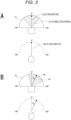
- Fig. 3 is an explanatory diagram about such display range control according to a line-of-sight direction.
- each of the front direction in the line-of-sight direction and the front direction in the field of view Fv is the direction of 0 degrees.
- a predetermined range about the direction of 0 degrees in the field of view Fv is cut from a camera captured image, as an image range to be displayed on the display unit 13.
- a range to be cut as a display target image range as described above is represented as "a cut range Rc".
- a front direction in the cut range Rc (a center direction of a view angle) is represented as "a cutting direction Dc" as illustrated. It can be said that the cutting direction Dc is regarded a direction indicating the center of the image in the cut range Rc, that is, the display image.
- the predetermined range about the direction of 0 degrees in the field of view Fv is basically regarded as the display range. This is because it is difficult to consider that the user keeps looking the display image for long hours with his or her line-of-sight direction deviating from the front direction and, in many cases, it can be assumed that the user faces frontward.
- Fig. 3B illustrates the example of the line-of-sight direction that is changed rightward by an angle a from the direction of 0 degrees.
- the cutting direction Dc is also changed rightward by the angle a from the direction of 0 degrees.
- control to change the cutting direction Dc following the change of the line-of-sight direction as described above in other words, the control to change the cut range Rc (the display range) following the change of the line-of-sight direction is represented as "line-of-sight following control" of a display range.
- the control to set the cutting direction Dc at the direction of 0 degrees in the field of view Fv particularly at the time when the line-of-sight direction is the direction of 0 degrees as described in the example illustrated in Fig. 3 is called "ordinary line-of-sight following control".
- the control unit 12 also performs, as the control related to the display of the camera captured images, viewpoint switching control of the display image in conjunction with the foregoing line-of-sight following control of the display range. It can be said that the viewpoint switching control is regarded as control to switch an image to be displayed on the display unit 13, among the camera captured images by the respective cameras 2. Note that, in the viewpoint switching control, the control unit 12 may receive each of the camera captured images from the server apparatus 4 and select an image to be displayed on the display unit 13, from the received camera captured images. Alternatively, the control unit 12 may selectively receive only a camera captured image by one of the cameras 2 serving as a switching destination viewpoint from the server apparatus 4 and display the received image on the display unit 13.
- control unit 12 occasionally performs control different from the ordinary viewpoint following control, as the viewpoint following control for the camera captured image of the switching destination viewpoint, in accordance with viewpoint switching. This control will be described later.
- the display unit 13 displays an image captured by the front camera 2 in Fig. 4 . It is also assumed that, at this time, the user deviates his or her line-of-sight direction rightward from the front direction (the direction of 0 degrees) as illustrated, in order to catch the specific object (the artist in the present example) who is at the relatively right side on the stage, in front of his or her sight (i.e., at the center of the display image).
- a deviation amount of the line-of-sight direction from the front direction at this time is defined as x degrees.
- the position of the specific object on the stage is represented as a position Po as illustrated.
- viewpoint switching to, for example, the left camera 2 is made from the foregoing state. Since the line-of-sight direction of the user is deviated rightward by x degrees from the front direction, the display image after the viewpoint switching corresponds to an image cut with the direction deviated rightward by x degrees from the front direction in the field of view Fv of the left camera 2 set at the cutting direction Dc.
- the display image after the viewpoint switching corresponds to an image cut with a direction deviated rightward by x degrees from the front direction in the field of view Fv of the right camera 2 set at the cutting direction Dc.
- the present embodiment proposes, as a display range deciding technique in viewpoint switching, the following deciding technique that does not make a decision on a display range, based on only information of a line-of-sight direction of a user like the ordinary line-of-sight following control, but makes a decision on a display range, using object position information of a specific object and camera position information.
- Fig. 5 is an explanatory diagram about a display range deciding technique as pattern 1.
- a display range of a camera captured image of a switching destination viewpoint is decided such that the specific object is displayed in the line-of-sight direction of the user in the state in which the line-of-sight direction of the user is the front direction. That is, after the viewpoint switching, if the line-of-sight direction of the user is directed to the front direction, the user is able to see the specific object in front of his or her sight (i.e., at the center of the display image).
- Such pattern 1 can be represented as a pattern for deciding the display range of the switching destination viewpoint image such that the specific object is displayed in the front direction of the line-of-sight direction of the user. It can be said that "the front direction of the line-of-sight direction of the user" as mentioned herein is regarded as a front direction defined with regard to a line-of-sight direction of a user.
- the exemplary case where the display range is decided such that the specific object is displayed in the front direction of the line-of-sight direction of the user is described here; however, it is not essential to cause the position where the specific object is displayed to strictly conform to the front direction of the line-of-sight direction of the user as long as the position can be regarded as being in the front direction.
- the position where the specific object is displayed is not limited to a position in the front direction of the line-of-sight direction of the user. It is sufficient that the position is, for example, in a predetermined direction such as a direction deviating from the front direction by a predetermined angle.
- the specific object which is present at the position Po in the present example is the object which the user has looked in the display image of the switching source viewpoint.
- pattern 1 of the present example the same applies to pattern 2 to be described later
- a display range of a camera captured image of a switching destination viewpoint is decided using the specific object which the user has looked in a display image from a switching source viewpoint, as the point of reference.
- Fig. 6 is an explanatory diagram about the display range deciding technique as pattern 2.
- a display range of a camera captured image of a switching destination viewpoint is decided such that the specific object is displayed on an extension of the line-of-sight direction of the user in a state in which the line-of-sight direction of the user conforms to the line-of-sight direction at the viewpoint switching. That is, after the viewpoint switching, the user is able to see the specific object in front of his or her sight while keeping the line-of-sight direction at the viewpoint switching.
- Such pattern 2 can be represented as a pattern for deciding the display range of the switching destination viewpoint image such that the specific target is displayed in the line-of-sight direction of the user at the viewpoint switching.
- Fig. 7 is an explanatory diagram about the display range deciding technique as pattern 3.
- Pattern 3 is a technique similar to pattern 1, and the display range of the camera captured image of the switching destination viewpoint is decided such that a specific space in the display target is displayed on an extension of the line-of-sight direction of the user in the state in which the line-of-sight direction of the user is the front direction.
- the specific space corresponds to the center of the stage.
- the central position of the stage is illustrated as a position Pc.
- control unit 12 acquires information of the position Pc from, for example, the communication apparatus 3 via the server apparatus 4.
- a display range is decided using a position of a specific object or specific space in a display target as the point of reference. Therefore, in making a display range decision of the embodiment, the object position information of a specific object is used.
- the camera 2 as the switching destination viewpoint in making the display range decision using the position of the specific object or specific space as the point of reference, it is necessary to grasp a direction in which the specific object or the specific space is present, in the field of view Fv of the camera 2 as the switching destination viewpoint. For this reason, in making the display range decision of the embodiment, the camera position information on the camera 2 as the switching destination viewpoint is used.
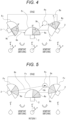
- Fig. 8 is a consideration diagram about viewpoint following control in the case of patterns 1 and 3.
- angle ⁇ represents an angle of a direction in which the specific object (position Po) or the specific space (position Pc) is present, in the field of view Fv of the camera 2 as the switching destination viewpoint.
- This angle ⁇ can be obtained on the basis of the camera position information on the camera 2 as the switching destination viewpoint and the object position information of the specific object or the position information of the specific space.
- Fig. 9 is a consideration diagram about viewpoint following control in the case of pattern 2.
- the display range decision is made using the position of the specific object as the point of reference. As illustrated in Fig. 9A , therefore, an angle ⁇ is used, which is an angle of a direction in which the specific object (position Po) is present in the field of view Fv of the camera 2 as the switching destination viewpoint. According to pattern 2, moreover, the display range is decided such that the specific object is displayed on the extension of the line-of-sight direction of the user in the state in which the line-of-sight direction of the user conforms to the line-of-sight direction at the viewpoint switching. For the viewpoint following control, therefore, an angle x is also used, which indicates the line-of-sight direction at the viewpoint switching illustrated in Fig. 9B .
- a direction of ⁇ degrees is set at the cutting direction Dc in the state in which the line-of-sight direction of the user is a direction of the angle x. It is therefore sufficient that, according to the line-of-sight following control in the case of pattern 2, a direction to be specified with an angle obtained by adding an offset represented by " ⁇ -x" to an angle of the line-of-sight direction estimated by the line-of-sight direction estimation unit 14 is decided as the cutting direction Dc.
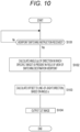
- processing illustrated in Fig. 10 is executed by the control unit 12 on the basis of a program stored in, for example, a predetermined storage apparatus such as a ROM.
- step S101 first, the control unit 12 waits for a viewpoint switching instruction.
- this viewpoint switching instruction for example, the control unit 12 waits for a viewpoint switching instruction which the user issues to the reproduction apparatus 1 through operation to the operation unit 15. It is assumed that this viewpoint switching instruction also contains the information of the switching destination viewpoint.
- the viewpoint switching is not necessarily executed on the basis of user's operation. It is also considered that the viewpoint switching is executed in accordance with establishment of a predetermined condition other than the operation. For example, the viewpoint switching is executed on the basis of switching instruction information added to a camera captured image or is executed in specific scene switching on the basis of a scene analysis result of a camera captured image.
- step S102 the control unit 12 calculates an angle ⁇ of a direction in which the specific target is present in the field of view Fv of a switching destination viewpoint.
- step S102 the control unit 12 calculates an angle ⁇ of a direction in which the specific object is present in the field of view Fv of the camera 2 as the switching destination viewpoint.
- step S102 the control unit 12 calculates an angle ⁇ of a direction in which the specific space is present in the field of view Fv of the camera 2 as the switching destination viewpoint.
- the control unit 12 uses the camera position information of the switching destination viewpoint, and the object position information of the specific object or the position information of the specific space.
- step S103 the control unit 12 calculates an offset to a viewpoint direction on the basis of the angle ⁇ .
- an offset is obtained by adding the angle ⁇ to the angle of the line-of-sight direction estimated by the line-of-sight direction estimation unit 14.
- the control unit 12 calculates an offset represented by " ⁇ -x", on the basis of the angle ⁇ and the angle x of the line-of-sight direction at the viewpoint switching.
- step S104 the control unit 12 performs cut image output processing. That is, the control unit 12 decides, as a cutting direction Dc, a direction that is specified with an angle obtained by adding the offset obtained in step S102 to the angle of the line-of-sight direction estimated by the line-of-sight direction estimation unit 14, and then cuts an image in a predetermined range about the cutting direction Dc, from a camera captured image of the switching destination viewpoint. The control unit 12 then outputs the cut image to the display unit 13.
- the control unit 12 ends a series of processing illustrated in Fig. 10 in accordance with execution of processing in step S104.
- control unit 12 in a case where the position of the specific object is moved, the control unit 12 successively recalculates the angle ⁇ on the basis of the object position information of the specific object and successively updates a value of the offset to be added to the angle of the line-of-sight direction.
- the embodiment is not limited to the foregoing specific example, and may adopt a variety of configurations as modifications.
- a determination whether or not the display range decision as the embodiment exemplified as patterns 1, 2, and 3 is made can be made on the basis of a type of a target which the user has looked in the display image of the switching source viewpoint.
- Fig. 11 is a flowchart illustrating processing as a modification for making a determination whether or not a display range decision as the embodiment as described above is made.
- step S201 the control unit 12 determines whether or not to perform line-of-sight offset control.
- the determination is a determination whether or not a display range decision is made using three pieces of information, that is, the camera position information of the switching destination viewpoint, the position information of the specific target, and the information of the line-of-sight direction estimated by the line-of-sight direction estimation unit 14, as exemplified as patterns 1, 2, and 3.
- the control unit 12 makes a determination based on a type of the target which the user has looked in the display image of the switching source viewpoint. Specifically, in the present example, the control unit 12 determines whether or not the target which the user has looked in the display image of the switching source viewpoint is the specific object (the artist in the present example).
- the determination whether or not the user has looked the specific object in the display image of the switching source viewpoint can be made by image analysis on the display image.
- the determination whether or not the specific object is located within the field of view Fv of the camera 2 as the switching source viewpoint may be made on the basis of the camera position information of the switching source viewpoint and the object position information of the specific object.
- the determination whether or not the user has looked the specific object can be made under a condition that the specific object has an image size equal to or more than a predetermined size or a condition that the specific object is in a certain range within the field of view Fv (e.g., a center range within the field of view Fv), in addition to the condition that the specific object is simply located in the switching source viewpoint image and a condition that the specific object is located in the field of view Fv of the switching source.
- a condition that the specific object has an image size equal to or more than a predetermined size or a condition that the specific object is in a certain range within the field of view Fv (e.g., a center range within the field of view Fv)
- a certain range within the field of view Fv e.g., a center range within the field of view Fv
- the control unit 12 obtains a result of the determination that the line-of-sight offset control is performed. In this case, the control unit 12 performs processing in step S102.
- the control unit 12 thus performs processing for the display range decision as the embodiment exemplified as patterns 1, 2, and 3.
- control unit 12 obtains a result of the determination that the line-of-sight offset control is not performed. In this case, the control unit 12 performs processing in step S202 to select ordinary line-of-sight following control.
- a technique of determining whether or not a display range decision as the embodiment is made, on the basis of a type of the target which the user has looked in the display image of the switching source viewpoint is not limited to the technique of determining whether or not the user has looked the specific object as described above.
- a technique can also be adopted, which determines that a display range decision as the embodiment is not made when the user has looked a target outside the stage, such as a spectator seat portion.
- an apparatus form of the reproduction apparatus 1 is not limited to an HMD.
- apparatus forms such as a smartphone, a tablet terminal, and a large display apparatus such as a television (TV) receiver are also conceivable.
- TV television
- the line-of-sight direction of the user can be estimated as an orientation of an apparatus.
- the orientation of the apparatus can be detected by, for example, a physical sensor such as an acceleration sensor or a gyro sensor.
- the line-of-sight direction of the user can be estimated by eye tracking.
- a display range decision as to a switching destination viewpoint image uses not only position information of each camera 2 as a switching destination viewpoint, but also information of an orientation of the camera 2 (pan, tilt, and roll directions).
- the orientation information of each camera 2 can be detected by, for example, an acceleration sensor, a gyro sensor, or the like provided to the camera 2.
- the orientation information of each camera 2 can also be detected by calibration using a board on which predetermined graphics are drawn. It can be said herein that the orientation information of each camera 2 is regarded as a line-of-sight direction from a viewpoint.
- viewpoint switching and the display range decision mainly in the pan direction (lateral direction).
- viewpoint switching and a display range decision can be made by the similar technique.
- information of a posture and orientation of a specific object is used in addition to position information of the specific object. For example, in a case where it is desired to catch the front of the face of the artist which is the specific object, the information of the posture and orientation of the specific object is used for the display range decision.
- the above description mentions the example of the sensor that detects the position of the specific object.
- a display target is, for example, a classical concert or the like and a seating position of an artist is a preset fixed position
- information of the preset fixed position can be used.
- a display range deciding technique is switched depending on an apparatus type of the reproduction apparatus 1. For example, it is considered that a display range after viewpoint switching is changed depending on whether the reproduction apparatus 1 is an HMD or another display device (e.g., a tablet terminal, a TV receiver). Specifically, when a specific object is located near an end of an image from a switching destination viewpoint, in a case of an HMD, the specific object is viewed with ease in such a manner that the specific object is located at the center of a display image. In a case of a tablet terminal or the like, on the other hand, it is not desirable that the end is filled with a predetermined color such as black as a non-image portion. It is therefore considered that the display range is decided such that an end of a display image frame conforms to the end of the image from the switching destination viewpoint.
- the display range deciding technique as the embodiment is also preferably applicable to a case where a display target is an object or a space in a virtual space such as a virtual reality (VR) space or an augmented reality (AR) space.
- a display target is an object or a space in a virtual space such as a virtual reality (VR) space or an augmented reality (AR) space.
- VR virtual reality
- AR augmented reality
- a program of an embodiment is a program for causing a computer apparatus such as a CPU to execute the processing as the reproduction apparatus 1.
- the program of the embodiment is a computer apparatus-readable program for causing a computer apparatus to execute processing, in switching a display image as to multiple-viewpoint images capable of displaying a display target from multiple viewpoints, from a switching source viewpoint image corresponding to a switching source viewpoint to a switching destination viewpoint image corresponding to a switching destination viewpoint, of deciding a display range of the switching destination viewpoint image on the basis of viewpoint position information of the switching destination viewpoint, specific target information which is information regarding a specific target in the display target, and line-of-sight direction information of an estimated orientation of a line-of-sight of a user to the display image.
- this program corresponds to, for example, a program for causing a computer apparatus to execute the processing described with reference to Fig. 10 , Fig. 11 , or the like.
- Such a program can be previously stored in, for example, a computer apparatus-readable storage medium such as a ROM, a hard disk drive (HDD), or a solid state drive (SSD).
- a computer apparatus-readable storage medium such as a ROM, a hard disk drive (HDD), or a solid state drive (SSD).
- a program can also be temporarily or permanently held (stored) in a removable storage medium such as a semiconductor memory, a memory card, an optical disk, a magneto-optical disk, or a magnetic disk.
- a removable storage medium can be provided in the form of packaged software.
- Such a program can be installed in a personal computer or the like from a removable storage medium or can also be downloaded from a download site onto a desired information processing apparatus such as a smartphone via a network such as a LAN or the Internet.
- an information processing apparatus as an embodiment includes a display range decision unit (a control unit 12) configured, in switching a display image as to multiple-viewpoint images capable of displaying a display target from multiple viewpoints, from a switching source viewpoint image corresponding to a switching source viewpoint to a switching destination viewpoint image corresponding to a switching destination viewpoint, to decide a display range of the switching destination viewpoint image on the basis of viewpoint position information of the switching destination viewpoint, specific target information which is information regarding a specific target in the display target, and line-of-sight direction information of an estimated orientation of a line-of-sight of a user to the display image.
- a display range decision unit configured, in switching a display image as to multiple-viewpoint images capable of displaying a display target from multiple viewpoints, from a switching source viewpoint image corresponding to a switching source viewpoint to a switching destination viewpoint image corresponding to a switching destination viewpoint, to decide a display range of the switching destination viewpoint image on the basis of viewpoint position information of the switching destination viewpoint, specific target information which is information regarding a specific target
- the display target is, for example, a target in a real space
- a viewpoint to the display target is a viewpoint of a camera that captures an image of the target.
- the display target is a target in a virtual space
- a viewpoint to the display target is a viewpoint to the display target set on the virtual space.
- the specific target information is information regarding the specific target in the display target. For example, if the display target is a music live show or the like in a real space, the specific target information can be information of a position, posture, and orientation of a specific object such as an artist on a stage, information of a position of a specific space in the display target, such as the center of the stage, and the like, as examples.
- a display range of a switching destination viewpoint image can be decided on the basis of the relationship between a position of a switching destination viewpoint and a position and the like of a specific target in a display target.
- the specific target information is information containing a position of the specific target.
- the position of the specific target is detected by image analysis.
- the specific target is, for example, a specific object such as an artist on a stage, to omit time and effort for attaching a sensor to the specific object.
- the position of the specific target is detected on the basis of a detection signal of a sensor attached to the specific target.
- the display range decision unit decides the display range, using information of a direction of a line-of-sight from the switching destination viewpoint.
- the display range decision unit decides the display range such that the specific target is displayed in a predetermined direction of a line-of-sight direction of the user (see patterns 1 and 3).
- the user is able to see the specific target in the predetermined direction by directing his or her line-of-sight direction to the predetermined direction.
- the display range decision unit decides the display range such that the specific target is displayed in a front direction of a line-of-sight direction of the user (see patterns 1 and 3).
- the specific target is a specific space in the display target (see pattern 3).
- the display range decision unit decides the display range such that the specific target is displayed in a line-of-sight direction of the user at the viewpoint switching (see pattern 2).
- the specific target is an object determined that the user has looked in the display image of the switching source viewpoint.
- the display range decision unit determines whether or not to make a decision on the display range using the viewpoint position information, the specific target information, and the line-of-sight direction information, on the basis of a type of the target which the user has looked in the display image of the switching source viewpoint.
- the display range decision unit determines not to make a display range decision using the foregoing three pieces of information.
- the display range decision unit makes a decision on the display range using the viewpoint position information, the specific target information, and the line-of-sight direction information (see Fig. 11 ).
- a display range decision method as the embodiment is a display range decision method including causing an information processing apparatus, in switching a display image as to multiple-viewpoint images capable of displaying a display target from multiple viewpoints, from a switching source viewpoint image corresponding to a switching source viewpoint to a switching destination viewpoint image corresponding to a switching destination viewpoint, to decide a display range of the switching destination viewpoint image on the basis of viewpoint position information of the switching destination viewpoint, specific target information which is information regarding a specific target in the display target, and line-of-sight direction information of an estimated orientation of a line-of-sight of a user to the display image.
- Such a display range decision method is also capable of providing functional effects similar to those of the foregoing information processing apparatus as the embodiment.
Landscapes
- Engineering & Computer Science (AREA)
- Theoretical Computer Science (AREA)
- General Engineering & Computer Science (AREA)
- Physics & Mathematics (AREA)
- General Physics & Mathematics (AREA)
- Human Computer Interaction (AREA)
- Multimedia (AREA)
- Signal Processing (AREA)
- Computer Vision & Pattern Recognition (AREA)
- User Interface Of Digital Computer (AREA)
- Controls And Circuits For Display Device (AREA)
Abstract
Description
- The present technology relates to an information processing apparatus, a display range decision method, and a program that make a decision on a display range as an image range to be displayed to a user, from an image displaying a display target.
- For example, in a display device such as a head mounted display (HMD), an image display range has been controlled in accordance with a line-of-sight direction of a user to be estimated from an orientation of the user's head, and the like. For example, in displaying a wide-angle image such as a panoramic image, a display range in the wide-angle image is changed following a change in line-of-sight direction of a user.
- In addition, some display devices have an image viewpoint switching function. That is, images respectively viewed from multiple viewpoints are displayed to a user while being switched.
- Note that
Patent Document 1 listed below can be cited as the related conventional technology.Patent Document 1 listed below discloses a technology for switching a virtual viewpoint in a virtual viewpoint image. - Patent Document 1:
Japanese Patent Application Laid-Open Publication No. 2018-92491 - Here, consideration will be given to a case where a display device, such as an HMD, that controls an image display range in accordance with a line-of-sight direction of a user has a viewpoint switching function. In combining display range control according to a line-of-sight direction with viewpoint switching, there is a possibility that a user may feel a sense of incongruity owing to the viewpoint switching unless an image display range after the viewpoint switching is controlled appropriately.
- The present technology has been made in view of the circumstances described above and aims to cause a user to less feel a sense of incongruity owing to viewpoint switching.
- An information processing apparatus according to the present technology includes a display range decision unit configured, in switching a display image as to multiple-viewpoint images capable of displaying a display target from multiple viewpoints, from a switching source viewpoint image corresponding to a switching source viewpoint to a switching destination viewpoint image corresponding to a switching destination viewpoint, to decide a display range of the switching destination viewpoint image on the basis of viewpoint position information of the switching destination viewpoint, specific target information which is information regarding a specific target in the display target, and line-of-sight direction information of an estimated orientation of a line-of-sight of a user to the display image.
- Here, if the display target is, for example, a target in a real space, a viewpoint to the display target is a viewpoint of a camera that captures an image of the target. Alternatively, if the display target is a target in a virtual space, a viewpoint to the display target is a viewpoint to the display target set on the virtual space. Moreover, the specific target information is information regarding the specific target in the display target. For example, if the display target is a music live show or the like in a real space, the specific target information can be information of a position, posture, and orientation of a specific object such as an artist on a stage, information of a position of a specific space in the display target, such as the center of the stage, and the like, as examples.
- According to the foregoing configuration, in a case where a display range of an image is controlled in accordance with a line-of-sight direction of a user, a display range of a switching destination viewpoint image can be decided on the basis of the relationship between a position of a switching destination viewpoint and a position and the like of a specific target in a display target.
- The foregoing information processing apparatus according to the present technology can have a configuration in which the specific target information is information containing a position of the specific target.
- With this configuration, it is possible to decide the display range of the switching destination viewpoint image on the basis of the relationship between the position of the switching destination viewpoint and the position of the specific target.
- The foregoing information processing apparatus according to the present technology can have a configuration in which the position of the specific target is detected by image analysis.
- With this configuration, it is possible to eliminate a necessity to attach a position detection sensor to the specific target in detecting the position of the specific target.
- The foregoing information processing apparatus according to the present technology can have a configuration in which the position of the specific target is detected on the basis of a detection signal of a sensor attached to the specific target.
- With this configuration, it is possible to eliminate a necessity to perform image analysis processing for detecting a position of the specific target.
- The foregoing information processing apparatus according to the present technology can have a configuration in which the display range decision unit decides the display range, using information of a direction of a line-of-sight from the switching destination viewpoint.
- With this configuration, it is possible to address a case where an observing direction from a viewpoint is changeable such as a case where an orientation of a camera that captures an image of the display target is changeable.
- The foregoing information processing apparatus according to the present technology can have a configuration in which the display range decision unit decides the display range such that the specific target is displayed in a predetermined direction of a line-of-sight direction of the user.
- With this configuration, after viewpoint switching, the user is able to see the specific target in the predetermined direction by directing his or her line-of-sight direction to the predetermined direction.
- The foregoing information processing apparatus according to the present technology can have a configuration in which the display range decision unit decides the display range such that the specific target is displayed in a front direction of a line-of-sight direction of the user.
- With this configuration, after the viewpoint switching, the user is able to see the specific target in front by directing his or her line-of-sight direction to the front direction.
- The foregoing information processing apparatus according to the present technology can have a configuration in which the specific target is a specific space in the display target.
- With this configuration, it is possible to decide the display range of the switching destination viewpoint image, using, for example, a space serving as an indication in the display target, such as the center of the stage, as the point of reference.
- The foregoing information processing apparatus according to the present technology can have a configuration in which the display range decision unit decides the display range such that the specific target is displayed in a line-of-sight direction of the user at viewpoint switching.
- With this configuration, after the viewpoint switching, the user is able to see the specific target in front while keeping the line-of-sight direction at the viewpoint switching.
- The foregoing information processing apparatus according to the present technology can have a configuration in which the specific target is an object determined that the user has looked in the display image of the switching source viewpoint.
- With this configuration, it is possible to decide the display range of the switching destination viewpoint image, using the object which the user has looked in the display image of the switching source viewpoint, as the point of reference.
- The foregoing information processing apparatus according to the present technology can have a configuration in which the display range decision unit determines whether or not to make a decision on the display range using the viewpoint position information, the specific target information, and the line-of-sight direction information, on the basis of a type of the target which the user has looked in the display image of the switching source viewpoint.
- With this configuration, it is possible to make an appropriate determination whether or not to make a display range decision using the viewpoint position information, the specific target information, and the line-of-sight direction information, on the basis of a type of the target which the user has looked. For example, when the user has looked a target outside the stage, such as a spectator seat portion, the display range decision unit determines not to make a display range decision using the foregoing three pieces of information.
- The foregoing information processing apparatus according to the present technology can have a configuration in which in a case where it is determined that the user has looked the specific object in the display image of the switching source viewpoint, the display range decision unit makes a decision on the display range using the viewpoint position information, the specific target information, and the line-of-sight direction information.
- With this configuration, in a case where the user has looked, for example, a target different from the specific object, such as a spectator seat portion, it is possible not to make a display range decision using the three pieces of information.
- In addition, a display range decision method according to the present technology is a display range decision method including causing an information processing apparatus, in switching a display image as to multiple-viewpoint images capable of displaying a display target from multiple viewpoints, from a switching source viewpoint image corresponding to a switching source viewpoint to a switching destination viewpoint image corresponding to a switching destination viewpoint, to decide a display range of the switching destination viewpoint image on the basis of viewpoint position information of the switching destination viewpoint, specific target information which is information regarding a specific target in the display target, and line-of-sight direction information of an estimated orientation of a line-of-sight of a user to the display image.
- Such a display range decision method also provides functional effects similar to those of the foregoing information processing apparatus according to the present technology.
- Furthermore, a program according to the present technology is a computer apparatus-readable program for causing a computer apparatus to execute processing, in switching a display image as to multiple-viewpoint images capable of displaying a display target from multiple viewpoints, from a switching source viewpoint image corresponding to a switching source viewpoint to a switching destination viewpoint image corresponding to a switching destination viewpoint, of deciding a display range of the switching destination viewpoint image on the basis of viewpoint position information of the switching destination viewpoint, specific target information which is information regarding a specific target in the display target, and line-of-sight direction information of an estimated orientation of a line-of-sight of a user to the display image.
- Such a program realizes the foregoing information processing apparatus according to the present technology.
-
-
Fig. 1 is a diagram illustrating a configuration example of a display system including an information processing apparatus as an embodiment according to the present technology. -
Fig. 2 is a diagram illustrating a layout example of cameras in the embodiment. -
Fig. 3 is an explanatory diagram about display range control according to a line-of-sight direction. -
Fig. 4 is a consideration diagram about a display range deciding technique after viewpoint switching. -
Fig. 5 is an explanatory diagram about a display range deciding technique aspattern 1 in the embodiment. -
Fig. 6 is an explanatory diagram about the display range deciding technique aspattern 2 in the embodiment. -
Fig. 7 is an explanatory diagram about the display range deciding technique aspattern 3 in the embodiment. -
Fig. 8 is a consideration diagram about viewpoint following control in the case ofpatterns -
Fig. 9 is a consideration diagram about viewpoint following control in the case ofpattern 2 in the embodiment. -
Fig. 10 is a flowchart illustrating an example of a specific processing procedure to be executed for achieving the display range deciding technique as the embodiment. -
Fig. 11 is a flowchart illustrating processing as a modification. - With reference to the accompanying drawings, an embodiment according to the present technology will be described below in the following order.
- <1. Display system as embodiment>
- <2. Display range deciding technique as embodiment>
- <3. Processing procedure>
- <4. Modifications>
- <5. Program>
- <6. Summary of embodiment>
- <7. The present technology>
-
Fig. 1 illustrates a configuration example of a display system including areproduction apparatus 1 which is one embodiment of an information processing apparatus according to the present technology. - As illustrated, the display system includes the
reproduction apparatus 1, a plurality ofcameras 2, acommunication apparatus 3, and aserver apparatus 4. - In the display system of the present example, images of a music live show performed in a real space are captured by the
cameras 2 and are distributed as display contents to thereproduction apparatus 1. It is assumed particularly in the present example that the images as the display contents are distributed live. Thereproduction apparatus 1 is, for example, a head mounted display (HMD) and is used in a state in which it is mounted to a user's head. - The captured images as the display contents are imported from the
cameras 2 to thecommunication apparatus 3. Thereafter, the captured images are uploaded onto theserver apparatus 4 and are distributed from theserver apparatus 4 to thereproduction apparatus 1. - It can be said herein that, in the display system of the present example, a music live show, of which the images are to be captured by the
respective cameras 2, is regarded as a target to be displayed as display contents to a user. In the present specification, a target to be displayed as display contents to a user is referred to as "a display target". - Each of the
cameras 2 is, for example, an image capturing apparatus that includes an image capturing element such as a charge coupled device (CCD) image sensor or a complementary metal oxide semiconductor (CMOS) image sensor and captures images. Thecameras 2 are placed at different positions to obtain captured images from different viewpoints, respectively, in a live venue. -
Fig. 2 illustrates a layout example of thecameras 2. - In the present example, a display target is a music live show and, as illustrated, the
cameras 2 are placed to capture images of a stage from different positions, respectively. It is assumed in the present example that thecameras 2 are respectively placed at a position where the stage is observed from the front, a position where the stage is observed from the left side, and a position where the stage is observed from the right side. - In the figure, the field of view Fv of each
camera 2 is schematically illustrated in conjunction with the position of thecamera 2. It is assumed in the present example that the field of view Fv of eachcamera 2 is, for example, 180 degrees, which covers a relatively wide range. That is, it can be said that a camera captured image is a wide-angle image. - Note that the case where the number of
cameras 2 is three is exemplified herein; however, it is sufficient that the number ofcameras 2 is at least two or more. - The
communication apparatus 3 includes an objectposition detection unit 31, acontrol unit 32, and acommunication unit 33. - The object
position detection unit 31 detects a position of a specific object in a display target. In the present example, specifically, the objectposition detection unit 31 detects a position of a person who is an artist performing a music live show. - A position of a specific object as an artist can be detected by various sensors. For example, a position of a specific object can be detected by image analysis on images captured by one or more cameras (image sensors) that are placed in a venue to capture images of the specific object. A position of a specific object can also be detected using a depth sensor. A position of a specific object as an artist can alternatively be detected on the basis of detection signals of physical sensors, such as acceleration sensors, gyro sensors, or global navigation satellite system (GNSS) sensors, attached to the specific object. Note that a position of a specific object can also be detected on the basis of both the image analysis and the detection signals of the physical sensors described above.
- Hereinafter, information on a position of a specific object detected by the object
position detection unit 31 is represented as "object position information". - The
communication unit 33 establishes data communications with external equipment in a wired or wireless manner. Thecommunication unit 33 of the present example establishes data communications with theserver apparatus 4 via a network NT. - Here, a variety of examples is assumed as a configuration of the network NT. Examples of the configuration assumed herein may include, in addition to the Internet, an intranet, an extranet, a local area network (LAN), a community antenna television (CATV) communication network, a virtual private network (VPN), a telephone line network, a mobile communication network, a satellite communication network, and the like. A variety of examples is also assumed as to a transmission medium that constitutes a part of the network NT or the entire network NT. Examples of the transmission medium utilizable herein may include a wired transmission medium such as IEEE (abbreviation for institute of electrical and electronics engineers) 1394, a universal serial bus (USB), power line communication, or a telephone line, and a wireless transmission medium such as an infrared transmission medium like IrDA (abbreviation for infrared data association), Bluetooth (registered trademark), a 802.11 wireless network, a mobile phone network, a satellite line, and a digital terrestrial network.
- The
control unit 32 includes a microcomputer including a central processing unit (CPU) and memory apparatuses such as a read only memory (ROM) and a random access memory (RAM), and controls theentire communication apparatus 3. Thecontrol unit 32 particularly performs control for uploading images captured by the respective cameras 2 (camera captured images) and object position information detected by the objectposition detection unit 31, onto theserver apparatus 4 via thecommunication unit 33. - The
control unit 32 also performs control for uploading, in addition to these camera captured images and the object position information, camera position information which is information indicating the positions where thecameras 2 are placed, onto theserver apparatus 4. - The
reproduction apparatus 1 includes acommunication unit 11, acontrol unit 12, adisplay unit 13, a line-of-sightdirection estimation unit 14, and anoperation unit 15. - The
communication unit 11 establishes data communications with external equipment in a wired or wireless manner. Particularly in the present example, thecommunication unit 11 establishes data communications with theserver apparatus 4 via the network NT. - The
display unit 13 includes, for example, a display capable of image display, such as a liquid crystal display (LCD) or an organic electroluminescence (EL) display, and displays various kinds of information to the user on the basis of an instruction from thecontrol unit 12. - The line-of-sight
direction estimation unit 14 estimates the line-of-sight direction of the user. - Specifically, the line-of-sight
direction estimation unit 14 of the present example includes a physical sensor, such as an acceleration sensor or a gyro sensor, that detects the motion of the user's head, and estimates a line-of-sight direction from a motion amount of the user's head. - Here, in a case where the user's head, to which the
reproduction apparatus 1 as an HMD is attached, turns, for example, right from a direction defined as a front direction (a direction of 0 degrees), it can be considered that an orientation of the user's line-of-sight is changed to the right direction. The line-of-sight direction of the user can therefore be estimated from the motion amount of the head. - In the present specification, the term "line-of-sight direction" of a user does not strictly refer to only an orientation of the eyeballs (an orientation of pupils), but broadly involves an orientation indirectly estimated from, for example, the orientation of the user's head as described above.
- The
operation unit 15 includes, for example, input devices such as various hardware keys, an operation dial, and a touch panel, detects an input operation by the user, and sends the input operation to thecontrol unit 12. Thecontrol unit 12 decides the operation of thereproduction apparatus 1 in accordance with the input operation by the user, and controls the respective units such that the respective units perform necessary operations. - The
control unit 12 includes a microcomputer including a CPU and memory apparatuses such as a read only memory (ROM) and a random access memory (RAM), and controls theentire communication apparatus 3. Thecontrol unit 12 particularly performs processing related to display of a camera captured image to be distributed from theserver apparatus 4. - Specifically, the
control unit 12 performs, as the processing related to display of a camera captured image, processing of controlling a display range which is an image range to be displayed to the user through thedisplay unit 13, of the entire range of the camera captured image, in accordance with the line-of-sight direction estimated by the line-of-sightdirection estimation unit 14. -
Fig. 3 is an explanatory diagram about such display range control according to a line-of-sight direction. - In the display range control according to the line-of-sight direction, the front direction defined as to the line-of-sight direction of the user and the front direction in the field of view Fv of each
camera 2 are each used as the point of reference. Here, as illustrated inFig. 3A , each of the front direction in the line-of-sight direction and the front direction in the field of view Fv is the direction of 0 degrees. - When the line-of-sight direction is the direction of 0 degrees as illustrated in
Fig. 3A , a predetermined range about the direction of 0 degrees in the field of view Fv is cut from a camera captured image, as an image range to be displayed on thedisplay unit 13. A range to be cut as a display target image range as described above is represented as "a cut range Rc". - In addition, a front direction in the cut range Rc (a center direction of a view angle) is represented as "a cutting direction Dc" as illustrated. It can be said that the cutting direction Dc is regarded a direction indicating the center of the image in the cut range Rc, that is, the display image.
- In the display range control according to the line-of-sight direction, as described above, when the line-of-sight direction is the direction of 0 degrees, the predetermined range about the direction of 0 degrees in the field of view Fv is basically regarded as the display range. This is because it is difficult to consider that the user keeps looking the display image for long hours with his or her line-of-sight direction deviating from the front direction and, in many cases, it can be assumed that the user faces frontward.
- Moreover, as exemplified in
Fig. 3B , in a case where the line-of-sight direction of the user is changed, the cutting direction Dc is changed following the change of the line-of-sight direction.Fig. 3B illustrates the example of the line-of-sight direction that is changed rightward by an angle a from the direction of 0 degrees. In this case, the cutting direction Dc is also changed rightward by the angle a from the direction of 0 degrees. - The control to change the cutting direction Dc following the change of the line-of-sight direction as described above, in other words, the control to change the cut range Rc (the display range) following the change of the line-of-sight direction is represented as "line-of-sight following control" of a display range.
- Here, with regard to the line-of-sight following control of the display range, the control to set the cutting direction Dc at the direction of 0 degrees in the field of view Fv particularly at the time when the line-of-sight direction is the direction of 0 degrees as described in the example illustrated in
Fig. 3 is called "ordinary line-of-sight following control". - In
Fig. 1 , thecontrol unit 12 also performs, as the control related to the display of the camera captured images, viewpoint switching control of the display image in conjunction with the foregoing line-of-sight following control of the display range. It can be said that the viewpoint switching control is regarded as control to switch an image to be displayed on thedisplay unit 13, among the camera captured images by therespective cameras 2. Note that, in the viewpoint switching control, thecontrol unit 12 may receive each of the camera captured images from theserver apparatus 4 and select an image to be displayed on thedisplay unit 13, from the received camera captured images. Alternatively, thecontrol unit 12 may selectively receive only a camera captured image by one of thecameras 2 serving as a switching destination viewpoint from theserver apparatus 4 and display the received image on thedisplay unit 13. - Moreover, the
control unit 12 occasionally performs control different from the ordinary viewpoint following control, as the viewpoint following control for the camera captured image of the switching destination viewpoint, in accordance with viewpoint switching. This control will be described later. - First, consideration will be given to a display range deciding technique after the viewpoint switching while referring to
Fig. 4 . - It is assumed herein that the ordinary line-of-sight following control is performed as the line-of-sight following control of the display range.
- For example, it is assumed that the
display unit 13 displays an image captured by thefront camera 2 inFig. 4 . It is also assumed that, at this time, the user deviates his or her line-of-sight direction rightward from the front direction (the direction of 0 degrees) as illustrated, in order to catch the specific object (the artist in the present example) who is at the relatively right side on the stage, in front of his or her sight (i.e., at the center of the display image). A deviation amount of the line-of-sight direction from the front direction at this time is defined as x degrees. - Note that, in the following, the position of the specific object on the stage is represented as a position Po as illustrated.
- It is assumed that viewpoint switching to, for example, the
left camera 2 is made from the foregoing state. Since the line-of-sight direction of the user is deviated rightward by x degrees from the front direction, the display image after the viewpoint switching corresponds to an image cut with the direction deviated rightward by x degrees from the front direction in the field of view Fv of theleft camera 2 set at the cutting direction Dc. - On the other hand, if the viewpoint switching to the
right camera 2 is made, since the line-of-sight direction of the user before the viewpoint switching is also deviated rightward by x degrees from the front direction, the display image after the viewpoint switching corresponds to an image cut with a direction deviated rightward by x degrees from the front direction in the field of view Fv of theright camera 2 set at the cutting direction Dc. - As is clear by reference to the cutting direction Dc as to each of the
left camera 2 and theright camera 2, under the ordinary line-of-sight following control, after the viewpoint switching, the user sometimes sees a target different from a target which the user has looked before the viewpoint switching. As a result, there is a possibility that a target to be caught in the display image considerably differs before and after the viewpoint switching. Therefore, there is a possibility that the user feels a sense of incongruity at the viewpoint switching. - Hence, the present embodiment proposes, as a display range deciding technique in viewpoint switching, the following deciding technique that does not make a decision on a display range, based on only information of a line-of-sight direction of a user like the ordinary line-of-sight following control, but makes a decision on a display range, using object position information of a specific object and camera position information.
-
Fig. 5 is an explanatory diagram about a display range deciding technique aspattern 1. - According to
pattern 1, a display range of a camera captured image of a switching destination viewpoint is decided such that the specific object is displayed in the line-of-sight direction of the user in the state in which the line-of-sight direction of the user is the front direction. That is, after the viewpoint switching, if the line-of-sight direction of the user is directed to the front direction, the user is able to see the specific object in front of his or her sight (i.e., at the center of the display image). -
Such pattern 1 can be represented as a pattern for deciding the display range of the switching destination viewpoint image such that the specific object is displayed in the front direction of the line-of-sight direction of the user. It can be said that "the front direction of the line-of-sight direction of the user" as mentioned herein is regarded as a front direction defined with regard to a line-of-sight direction of a user. - Note that the exemplary case where the display range is decided such that the specific object is displayed in the front direction of the line-of-sight direction of the user is described here; however, it is not essential to cause the position where the specific object is displayed to strictly conform to the front direction of the line-of-sight direction of the user as long as the position can be regarded as being in the front direction. Alternatively, the position where the specific object is displayed is not limited to a position in the front direction of the line-of-sight direction of the user. It is sufficient that the position is, for example, in a predetermined direction such as a direction deviating from the front direction by a predetermined angle. With this configuration, after the viewpoint switching, if the user directs the line-of-sight direction to the predetermined direction, the user is able to see the object, which the user has looked before the viewpoint switching, in front. That is, by bringing about the state in which the line-of-sight direction is directed to the preset predetermined direction, the user is able to see the object, which the user has looked before the viewpoint switching, in front. It is therefore possible to cause the user to less feel a sense of incongruity owing to the viewpoint switching.
- Here, the specific object which is present at the position Po in the present example is the object which the user has looked in the display image of the switching source viewpoint. According to
pattern 1 of the present example (the same applies topattern 2 to be described later), a display range of a camera captured image of a switching destination viewpoint is decided using the specific object which the user has looked in a display image from a switching source viewpoint, as the point of reference. -
Fig. 6 is an explanatory diagram about the display range deciding technique aspattern 2. - According to
pattern 2, a display range of a camera captured image of a switching destination viewpoint is decided such that the specific object is displayed on an extension of the line-of-sight direction of the user in a state in which the line-of-sight direction of the user conforms to the line-of-sight direction at the viewpoint switching. That is, after the viewpoint switching, the user is able to see the specific object in front of his or her sight while keeping the line-of-sight direction at the viewpoint switching.Such pattern 2 can be represented as a pattern for deciding the display range of the switching destination viewpoint image such that the specific target is displayed in the line-of-sight direction of the user at the viewpoint switching. -
Fig. 7 is an explanatory diagram about the display range deciding technique aspattern 3. -
Pattern 3 is a technique similar topattern 1, and the display range of the camera captured image of the switching destination viewpoint is decided such that a specific space in the display target is displayed on an extension of the line-of-sight direction of the user in the state in which the line-of-sight direction of the user is the front direction. Here, in the present example, the specific space corresponds to the center of the stage. In the figure, the central position of the stage is illustrated as a position Pc. - It is considered herein that the
control unit 12 acquires information of the position Pc from, for example, thecommunication apparatus 3 via theserver apparatus 4. - As described above using
patterns 1 to 3, according to the display range deciding technique of the embodiment, a display range is decided using a position of a specific object or specific space in a display target as the point of reference. Therefore, in making a display range decision of the embodiment, the object position information of a specific object is used. - In addition, with regard to the
camera 2 as the switching destination viewpoint, in making the display range decision using the position of the specific object or specific space as the point of reference, it is necessary to grasp a direction in which the specific object or the specific space is present, in the field of view Fv of thecamera 2 as the switching destination viewpoint. For this reason, in making the display range decision of the embodiment, the camera position information on thecamera 2 as the switching destination viewpoint is used. - Next, consideration will be given to viewpoint following control in a case where a display range decision is made in accordance with
patterns 1 to 3 described above. -
Fig. 8 is a consideration diagram about viewpoint following control in the case ofpatterns - As described above, in making the display range decision using the position of the specific object or specific space as the point of reference, it is necessary to grasp a direction in which the specific object or the specific space is present, in the field of view Fv of the
camera 2 as the switching destination viewpoint. InFig. 8 , "angle α" represents an angle of a direction in which the specific object (position Po) or the specific space (position Pc) is present, in the field of view Fv of thecamera 2 as the switching destination viewpoint. - This angle α can be obtained on the basis of the camera position information on the
camera 2 as the switching destination viewpoint and the object position information of the specific object or the position information of the specific space. - It is sufficient in
patterns patterns direction estimation unit 14 is decided as the cutting direction Dc. -
Fig. 9 is a consideration diagram about viewpoint following control in the case ofpattern 2. - According to
pattern 2, the display range decision is made using the position of the specific object as the point of reference. As illustrated inFig. 9A , therefore, an angle α is used, which is an angle of a direction in which the specific object (position Po) is present in the field of view Fv of thecamera 2 as the switching destination viewpoint. According topattern 2, moreover, the display range is decided such that the specific object is displayed on the extension of the line-of-sight direction of the user in the state in which the line-of-sight direction of the user conforms to the line-of-sight direction at the viewpoint switching. For the viewpoint following control, therefore, an angle x is also used, which indicates the line-of-sight direction at the viewpoint switching illustrated inFig. 9B . - It is sufficient in
pattern 2 that a direction of α degrees is set at the cutting direction Dc in the state in which the line-of-sight direction of the user is a direction of the angle x. It is therefore sufficient that, according to the line-of-sight following control in the case ofpattern 2, a direction to be specified with an angle obtained by adding an offset represented by "α-x" to an angle of the line-of-sight direction estimated by the line-of-sightdirection estimation unit 14 is decided as the cutting direction Dc. - With reference to a flowchart of
Fig. 10 , next, a description will be given of a specific processing procedure for achieving the display range deciding technique described above as the embodiment. - In the present example, processing illustrated in
Fig. 10 is executed by thecontrol unit 12 on the basis of a program stored in, for example, a predetermined storage apparatus such as a ROM. - In step S101, first, the
control unit 12 waits for a viewpoint switching instruction. As this viewpoint switching instruction, for example, thecontrol unit 12 waits for a viewpoint switching instruction which the user issues to thereproduction apparatus 1 through operation to theoperation unit 15. It is assumed that this viewpoint switching instruction also contains the information of the switching destination viewpoint. - Note that the viewpoint switching is not necessarily executed on the basis of user's operation. It is also considered that the viewpoint switching is executed in accordance with establishment of a predetermined condition other than the operation. For example, the viewpoint switching is executed on the basis of switching instruction information added to a camera captured image or is executed in specific scene switching on the basis of a scene analysis result of a camera captured image.
- In a case where the
control unit 12 receives the viewpoint switching instruction, the processing proceeds to step S102 in which thecontrol unit 12 calculates an angle α of a direction in which the specific target is present in the field of view Fv of a switching destination viewpoint. - In the case of adopting the display range deciding technique according to
patterns control unit 12 calculates an angle α of a direction in which the specific object is present in the field of view Fv of thecamera 2 as the switching destination viewpoint. In the case of adopting the display range deciding technique according topattern 3, in step S102, thecontrol unit 12 calculates an angle α of a direction in which the specific space is present in the field of view Fv of thecamera 2 as the switching destination viewpoint. - In calculating this angle α, the
control unit 12 uses the camera position information of the switching destination viewpoint, and the object position information of the specific object or the position information of the specific space. - In step S103 subsequent to step S102, the
control unit 12 calculates an offset to a viewpoint direction on the basis of the angle α. In the case of adopting the display range deciding technique according topatterns direction estimation unit 14. On the other hand, in the case of adopting the display range deciding technique according topattern 2, in step S103, thecontrol unit 12 calculates an offset represented by "α-x", on the basis of the angle α and the angle x of the line-of-sight direction at the viewpoint switching. - In step S104 subsequent to step S103, the
control unit 12 performs cut image output processing. That is, thecontrol unit 12 decides, as a cutting direction Dc, a direction that is specified with an angle obtained by adding the offset obtained in step S102 to the angle of the line-of-sight direction estimated by the line-of-sightdirection estimation unit 14, and then cuts an image in a predetermined range about the cutting direction Dc, from a camera captured image of the switching destination viewpoint. Thecontrol unit 12 then outputs the cut image to thedisplay unit 13. - The
control unit 12 ends a series of processing illustrated inFig. 10 in accordance with execution of processing in step S104. - Note that in the case of adopting
patterns control unit 12 successively recalculates the angle α on the basis of the object position information of the specific object and successively updates a value of the offset to be added to the angle of the line-of-sight direction. - The embodiment is not limited to the foregoing specific example, and may adopt a variety of configurations as modifications.
- For example, a determination whether or not the display range decision as the embodiment exemplified as
patterns -
Fig. 11 is a flowchart illustrating processing as a modification for making a determination whether or not a display range decision as the embodiment as described above is made. - Note that processing similar to the processing described with reference to
Fig. 10 is denoted by the same reference sign inFig. 11 ; therefore, the redundant description will not be given here. - In this case, in a case where the
control unit 12 determines in step S101 that thecontrol unit 12 receives a viewpoint switching instruction, the processing proceeds to step S201 in which thecontrol unit 12 determines whether or not to perform line-of-sight offset control. Specifically, the determination is a determination whether or not a display range decision is made using three pieces of information, that is, the camera position information of the switching destination viewpoint, the position information of the specific target, and the information of the line-of-sight direction estimated by the line-of-sightdirection estimation unit 14, as exemplified aspatterns control unit 12 makes a determination based on a type of the target which the user has looked in the display image of the switching source viewpoint. Specifically, in the present example, thecontrol unit 12 determines whether or not the target which the user has looked in the display image of the switching source viewpoint is the specific object (the artist in the present example). - Here, the determination whether or not the user has looked the specific object in the display image of the switching source viewpoint can be made by image analysis on the display image. Alternatively, the determination whether or not the specific object is located within the field of view Fv of the
camera 2 as the switching source viewpoint may be made on the basis of the camera position information of the switching source viewpoint and the object position information of the specific object. At this time, the determination whether or not the user has looked the specific object can be made under a condition that the specific object has an image size equal to or more than a predetermined size or a condition that the specific object is in a certain range within the field of view Fv (e.g., a center range within the field of view Fv), in addition to the condition that the specific object is simply located in the switching source viewpoint image and a condition that the specific object is located in the field of view Fv of the switching source. - In a case where the target which the user has looked in the display image of the switching source viewpoint is the specific object in step S201, the
control unit 12 obtains a result of the determination that the line-of-sight offset control is performed. In this case, thecontrol unit 12 performs processing in step S102. Thecontrol unit 12 thus performs processing for the display range decision as the embodiment exemplified aspatterns - On the other hand, in a case where the target which the user has looked in the display image of the switching source viewpoint is not the specific object in step S201, the
control unit 12 obtains a result of the determination that the line-of-sight offset control is not performed. In this case, thecontrol unit 12 performs processing in step S202 to select ordinary line-of-sight following control. - Through the processing described above, it is possible to prevent the user from feeling a sense of incongruity owing to viewpoint switching by indiscriminately making a display range decision using the three pieces of information.
- Note that a technique of determining whether or not a display range decision as the embodiment is made, on the basis of a type of the target which the user has looked in the display image of the switching source viewpoint is not limited to the technique of determining whether or not the user has looked the specific object as described above. For example, a technique can also be adopted, which determines that a display range decision as the embodiment is not made when the user has looked a target outside the stage, such as a spectator seat portion.
- Here, the above description concerns an HMD as an example of the
reproduction apparatus 1; however, an apparatus form of thereproduction apparatus 1 is not limited to an HMD. For example, apparatus forms such as a smartphone, a tablet terminal, and a large display apparatus such as a television (TV) receiver are also conceivable. For example, in a case of a portable apparatus form such as a smartphone or a tablet terminal, the line-of-sight direction of the user can be estimated as an orientation of an apparatus. The orientation of the apparatus can be detected by, for example, a physical sensor such as an acceleration sensor or a gyro sensor. - Moreover, in a case of a stationary apparatus form such as a large display apparatus such as a television(TV) receiver, the line-of-sight direction of the user can be estimated by eye tracking.
- Moreover, the above description has been given on the assumption that the orientation of each
camera 2 is fixed. In a case where a change in orientation of each camera is allowed, a display range decision as to a switching destination viewpoint image uses not only position information of eachcamera 2 as a switching destination viewpoint, but also information of an orientation of the camera 2 (pan, tilt, and roll directions). The orientation information of eachcamera 2 can be detected by, for example, an acceleration sensor, a gyro sensor, or the like provided to thecamera 2. Alternatively, the orientation information of eachcamera 2 can also be detected by calibration using a board on which predetermined graphics are drawn. It can be said herein that the orientation information of eachcamera 2 is regarded as a line-of-sight direction from a viewpoint. - Furthermore, the above description concerns the viewpoint switching and the display range decision mainly in the pan direction (lateral direction). Also in the tilt direction, viewpoint switching and a display range decision can be made by the similar technique. In the case of the tilt direction, it is also considered that information of a posture and orientation of a specific object is used in addition to position information of the specific object. For example, in a case where it is desired to catch the front of the face of the artist which is the specific object, the information of the posture and orientation of the specific object is used for the display range decision.
- Moreover, the above description mentions the example of the sensor that detects the position of the specific object. Alternatively, in a case where a display target is, for example, a classical concert or the like and a seating position of an artist is a preset fixed position, information of the preset fixed position can be used.
- It is also considered that a display range deciding technique is switched depending on an apparatus type of the
reproduction apparatus 1. For example, it is considered that a display range after viewpoint switching is changed depending on whether thereproduction apparatus 1 is an HMD or another display device (e.g., a tablet terminal, a TV receiver). Specifically, when a specific object is located near an end of an image from a switching destination viewpoint, in a case of an HMD, the specific object is viewed with ease in such a manner that the specific object is located at the center of a display image. In a case of a tablet terminal or the like, on the other hand, it is not desirable that the end is filled with a predetermined color such as black as a non-image portion. It is therefore considered that the display range is decided such that an end of a display image frame conforms to the end of the image from the switching destination viewpoint. - Moreover, the above description mentions the example of the specific object or specific space which is an object or space on a real space. Alternatively, the display range deciding technique as the embodiment is also preferably applicable to a case where a display target is an object or a space in a virtual space such as a virtual reality (VR) space or an augmented reality (AR) space.
- The above description concerns the information processing apparatus (the reproduction apparatus 1) as the embodiment. A program of an embodiment is a program for causing a computer apparatus such as a CPU to execute the processing as the
reproduction apparatus 1. - The program of the embodiment is a computer apparatus-readable program for causing a computer apparatus to execute processing, in switching a display image as to multiple-viewpoint images capable of displaying a display target from multiple viewpoints, from a switching source viewpoint image corresponding to a switching source viewpoint to a switching destination viewpoint image corresponding to a switching destination viewpoint, of deciding a display range of the switching destination viewpoint image on the basis of viewpoint position information of the switching destination viewpoint, specific target information which is information regarding a specific target in the display target, and line-of-sight direction information of an estimated orientation of a line-of-sight of a user to the display image.
- That is, this program corresponds to, for example, a program for causing a computer apparatus to execute the processing described with reference to
Fig. 10 ,Fig. 11 , or the like. - Such a program can be previously stored in, for example, a computer apparatus-readable storage medium such as a ROM, a hard disk drive (HDD), or a solid state drive (SSD). Alternatively, such a program can also be temporarily or permanently held (stored) in a removable storage medium such as a semiconductor memory, a memory card, an optical disk, a magneto-optical disk, or a magnetic disk. Moreover, such a removable storage medium can be provided in the form of packaged software.
- Moreover, such a program can be installed in a personal computer or the like from a removable storage medium or can also be downloaded from a download site onto a desired information processing apparatus such as a smartphone via a network such as a LAN or the Internet.
- As described above, an information processing apparatus (a reproduction apparatus 1) as an embodiment includes a display range decision unit (a control unit 12) configured, in switching a display image as to multiple-viewpoint images capable of displaying a display target from multiple viewpoints, from a switching source viewpoint image corresponding to a switching source viewpoint to a switching destination viewpoint image corresponding to a switching destination viewpoint, to decide a display range of the switching destination viewpoint image on the basis of viewpoint position information of the switching destination viewpoint, specific target information which is information regarding a specific target in the display target, and line-of-sight direction information of an estimated orientation of a line-of-sight of a user to the display image.
- Here, if the display target is, for example, a target in a real space, a viewpoint to the display target is a viewpoint of a camera that captures an image of the target. Alternatively, if the display target is a target in a virtual space, a viewpoint to the display target is a viewpoint to the display target set on the virtual space. Moreover, the specific target information is information regarding the specific target in the display target. For example, if the display target is a music live show or the like in a real space, the specific target information can be information of a position, posture, and orientation of a specific object such as an artist on a stage, information of a position of a specific space in the display target, such as the center of the stage, and the like, as examples.
- According to the foregoing configuration, in a case where a display range of an image is controlled in accordance with a line-of-sight direction of a user, a display range of a switching destination viewpoint image can be decided on the basis of the relationship between a position of a switching destination viewpoint and a position and the like of a specific target in a display target.
- It is therefore possible to prevent a target to be caught in a display image from considerably differing before and after viewpoint switching and to cause a user to less feel a sense of incongruity owing to viewpoint switching.
- Moreover, in the information processing apparatus as the embodiment, the specific target information is information containing a position of the specific target.
- With this configuration, it is possible to decide the display range of the switching destination viewpoint image on the basis of the relationship between the position of the switching destination viewpoint and the position of the specific target.
- It is therefore possible to prevent a target to be caught in a display image from considerably differing before and after viewpoint switching and to cause a user to less feel a sense of incongruity owing to viewpoint switching.
- Moreover, in the information processing apparatus as the embodiment, the position of the specific target is detected by image analysis.
- With this configuration, it is possible to eliminate a necessity to attach a position detection sensor to the specific target in detecting the position of the specific target.
- It is accordingly possible, in a case where the specific target is, for example, a specific object such as an artist on a stage, to omit time and effort for attaching a sensor to the specific object.
- Moreover, in the information processing apparatus as the embodiment, the position of the specific target is detected on the basis of a detection signal of a sensor attached to the specific target.
- With this configuration, it is possible to eliminate a necessity to perform image analysis processing for detecting a position of the specific target.
- It is therefore possible to reduce a processing burden in detecting the position of a specific target.
- Furthermore, in the information processing apparatus as the embodiment, the display range decision unit decides the display range, using information of a direction of a line-of-sight from the switching destination viewpoint.
- With this configuration, it is possible to address a case where a direction of a line-of-sight from a viewpoint is changeable such as a case where an orientation of a camera that captures an image of a display target is changeable.
- It is therefore possible to permit a change in view angle of a display target from a viewpoint and to improve the degree of freedom as to image contents to be displayed to a user.
- Moreover, in the information processing apparatus as the embodiment, the display range decision unit decides the display range such that the specific target is displayed in a predetermined direction of a line-of-sight direction of the user (see
patterns 1 and 3). - With this configuration, after the viewpoint switching, the user is able to see the specific target in the predetermined direction by directing his or her line-of-sight direction to the predetermined direction.
- It is therefore possible to cause the user to less feel a sense of incongruity owing to the viewpoint switching.
- Moreover, in the information processing apparatus as the embodiment, the display range decision unit decides the display range such that the specific target is displayed in a front direction of a line-of-sight direction of the user (see
patterns 1 and 3). - With this configuration, after the viewpoint switching, the user is able to see the specific target in front by directing his or her line-of-sight direction to the front direction.
- It is therefore possible to cause the user to less feel a sense of incongruity owing to the viewpoint switching.
- Furthermore, in the information processing apparatus as the embodiment, the specific target is a specific space in the display target (see pattern 3).
- With this configuration, it is possible to decide the display range of the switching destination viewpoint image, using, for example, a space serving as an indication in the display target, such as the center of the stage, as the point of reference.
- It is therefore possible to prevent a position, which the user has seen, in the display target from being lost after the viewpoint switching and to cause the user to less feel a sense of incongruity owing to the viewpoint switching.
- Moreover, in the information processing apparatus as the embodiment, the display range decision unit decides the display range such that the specific target is displayed in a line-of-sight direction of the user at the viewpoint switching (see pattern 2).
- With this configuration, after the viewpoint switching, the user is able to see the specific target in front while keeping the line-of-sight direction at the viewpoint switching.
- It is therefore possible to prevent a position, which the user has seen, in the display target from being lost after the viewpoint switching and to cause the user to less feel a sense of incongruity owing to the viewpoint switching.
- Further, in the information processing apparatus as the embodiment, the specific target is an object determined that the user has looked in the display image of the switching source viewpoint.
- With this configuration, it is possible to decide the display range of the switching destination viewpoint image, using the object which the user has looked in the display image of the switching source viewpoint, as the point of reference.
- It is therefore possible to cause the object, which the user has successively looked even after the viewpoint switching, to be caught in the display image and to cause the user to less feel a sense of incongruity owing to the viewpoint switching.
- Furthermore, in the information processing apparatus as the embodiment, the display range decision unit determines whether or not to make a decision on the display range using the viewpoint position information, the specific target information, and the line-of-sight direction information, on the basis of a type of the target which the user has looked in the display image of the switching source viewpoint.
- With this configuration, it is possible to make an appropriate determination whether or not to make a display range decision using the viewpoint position information, the specific target information, and the line-of-sight direction information, on the basis of a type of the target which the user has looked. For example, when the user has looked a target outside the stage, such as a spectator seat portion, the display range decision unit determines not to make a display range decision using the foregoing three pieces of information.
- It is therefore possible to prevent the user from feeling a sense of incongruity owing to the viewpoint switching by indiscriminately making a display range decision using the three pieces of information.
- Moreover, in the information processing apparatus as the embodiment, in a case where it is determined that the user has looked the specific object in the display image of the switching source viewpoint, the display range decision unit makes a decision on the display range using the viewpoint position information, the specific target information, and the line-of-sight direction information (see
Fig. 11 ). - With this configuration, in a case where the user has looked, for example, a target different from the specific object, such as a spectator seat portion, it is possible not to make a display range decision using the three pieces of information.
- It is therefore possible to prevent the user from feeling a sense of incongruity owing to the viewpoint switching by indiscriminately making a display range decision using the three pieces of information.
- In addition, a display range decision method as the embodiment is a display range decision method including causing an information processing apparatus, in switching a display image as to multiple-viewpoint images capable of displaying a display target from multiple viewpoints, from a switching source viewpoint image corresponding to a switching source viewpoint to a switching destination viewpoint image corresponding to a switching destination viewpoint, to decide a display range of the switching destination viewpoint image on the basis of viewpoint position information of the switching destination viewpoint, specific target information which is information regarding a specific target in the display target, and line-of-sight direction information of an estimated orientation of a line-of-sight of a user to the display image.
- Such a display range decision method is also capable of providing functional effects similar to those of the foregoing information processing apparatus as the embodiment.
- Note that the advantageous effects described in the present specification are merely exemplary and not limitative, and there may be achieved other advantageous effects.
- Note that the present technology can also adopt the following configurations.
- (1) An information processing apparatus including
a display range decision unit configured, in switching a display image as to multiple-viewpoint images capable of displaying a display target from multiple viewpoints, from a switching source viewpoint image corresponding to a switching source viewpoint to a switching destination viewpoint image corresponding to a switching destination viewpoint, to decide a display range of the switching destination viewpoint image on the basis of viewpoint position information of the switching destination viewpoint, specific target information which is information regarding a specific target in the display target, and line-of-sight direction information of an estimated orientation of a line-of-sight of a user to the display image. - (2) The information processing apparatus as recited in (1), in which
the specific target information is information containing a position of the specific target. - (3) The information processing apparatus as recited in (2), in which
the position of the specific target is detected by image analysis. - (4) The information processing apparatus as recited in (2) or (3), in which
the position of the specific target is detected on the basis of a detection signal of a sensor attached to the specific target. - (5) The information processing apparatus as recited in any of (1) to (4), in which
the display range decision unit decides the display range, using information of a direction of a line-of-sight from the switching destination viewpoint. - (6) The information processing apparatus as recited in any of (1) to (5), in which
the display range decision unit decides the display range such that the specific target is displayed in a predetermined direction of a line-of-sight direction of the user. - (7) The information processing apparatus as recited in (5), in which
the display range decision unit decides the display range such that the specific target is displayed in a front direction of a line-of-sight direction of the user. - (8) The information processing apparatus as recited in (6) or (7), in which
the specific target is a specific space in the display target. - (9) The information processing apparatus as recited in any of (1) to (5), in which
the display range decision unit decides the display range such that the specific target is displayed in a line-of-sight direction of the user at viewpoint switching. - (10) The information processing apparatus as recited in any of (1) to (7) and (9), in which
the specific target is an object determined that the user has looked in the display image of the switching source viewpoint. - (11) The information processing apparatus as recited in any of (1) to (10), in which
the display range decision unit determines whether or not to make a decision on the display range using the viewpoint position information, the specific target information, and the line-of-sight direction information, on the basis of a type of the target which the user has looked in the display image of the switching source viewpoint. - (12) The information processing apparatus as recited in (11), in which
in a case where it is determined that the user has looked the specific object in the display image of the switching source viewpoint, the display range decision unit makes a decision on the display range using the viewpoint position information, the specific target information, and the line-of-sight direction information. - (13) A display range decision method including
causing an information processing apparatus, in switching a display image as to multiple-viewpoint images capable of displaying a display target from multiple viewpoints, from a switching source viewpoint image corresponding to a switching source viewpoint to a switching destination viewpoint image corresponding to a switching destination viewpoint, to decide a display range of the switching destination viewpoint image on the basis of viewpoint position information of the switching destination viewpoint, specific target information which is information regarding a specific target in the display target, and line-of-sight direction information of an estimated orientation of a line-of-sight of a user to the display image. - (14) A computer apparatus-readable program for causing a computer apparatus to execute
processing, in switching a display image as to multiple-viewpoint images capable of displaying a display target from multiple viewpoints, from a switching source viewpoint image corresponding to a switching source viewpoint to a switching destination viewpoint image corresponding to a switching destination viewpoint, of deciding a display range of the switching destination viewpoint image on the basis of viewpoint position information of the switching destination viewpoint, specific target information which is information regarding a specific target in the display target, and line-of-sight direction information of an estimated orientation of a line-of-sight of a user to the display image. -
- 1
- Reproduction apparatus
- 2
- Camera
- 3
- Communication apparatus
- 4
- Server apparatus
- NT
- Network
- 11
- Communication unit
- 12
- Control unit
- 13
- Display unit
- 14
- Line-of-sight direction estimation unit
- 15
- Operation unit
- 31
- Object position detection unit
- 32
- Control unit
- 33
- Communication unit
- Fv
- Field of view
- Rc
- Cut range
- Dc
- Cutting direction
Claims (14)
- An information processing apparatus comprising
a display range decision unit configured, in switching a display image as to multiple-viewpoint images capable of displaying a display target from multiple viewpoints, from a switching source viewpoint image corresponding to a switching source viewpoint to a switching destination viewpoint image corresponding to a switching destination viewpoint, to decide a display range of the switching destination viewpoint image on a basis of viewpoint position information of the switching destination viewpoint, specific target information comprising information regarding a specific target in the display target, and line-of-sight direction information of an estimated orientation of a line-of-sight of a user to the display image. - The information processing apparatus according to claim 1, wherein
the specific target information comprises information containing a position of the specific target. - The information processing apparatus according to claim 2, wherein
the position of the specific target is detected by image analysis. - The information processing apparatus according to claim 2, wherein
the position of the specific target is detected on a basis of a detection signal of a sensor attached to the specific target. - The information processing apparatus according to claim 1, wherein
the display range decision unit decides the display range, using information of a direction of a line-of-sight from the switching destination viewpoint. - The information processing apparatus according to claim 1, wherein
the display range decision unit decides the display range such that the specific target is displayed in a predetermined direction of a line-of-sight direction of the user. - The information processing apparatus according to claim 5, wherein
the display range decision unit decides the display range such that the specific target is displayed in a front direction of a line-of-sight direction of the user. - The information processing apparatus according to claim 6, wherein
the specific target comprises a specific space in the display target. - The information processing apparatus according to claim 1, wherein
the display range decision unit decides the display range such that the specific target is displayed in a line-of-sight direction of the user at viewpoint switching. - The information processing apparatus according to claim 1, wherein
the specific target comprises an object determined that the user has looked in the display image of the switching source viewpoint. - The information processing apparatus according to claim 1, wherein
the display range decision unit determines whether or not to make a decision on the display range using the viewpoint position information, the specific target information, and the line-of-sight direction information, on a basis of a type of the target which the user has looked in the display image of the switching source viewpoint. - The information processing apparatus according to claim 11, wherein
in a case where it is determined that the user has looked the specific object in the display image of the switching source viewpoint, the display range decision unit makes a decision on the display range using the viewpoint position information, the specific target information, and the line-of-sight direction information. - A display range decision method comprising
causing an information processing apparatus, in switching a display image as to multiple-viewpoint images capable of displaying a display target from multiple viewpoints, from a switching source viewpoint image corresponding to a switching source viewpoint to a switching destination viewpoint image corresponding to a switching destination viewpoint, to decide a display range of the switching destination viewpoint image on a basis of viewpoint position information of the switching destination viewpoint, specific target information comprising information regarding a specific target in the display target, and line-of-sight direction information of an estimated orientation of a line-of-sight of a user to the display image. - A computer apparatus-readable program for causing a computer apparatus to execute
processing, in switching a display image as to multiple-viewpoint images capable of displaying a display target from multiple viewpoints, from a switching source viewpoint image corresponding to a switching source viewpoint to a switching destination viewpoint image corresponding to a switching destination viewpoint, of deciding a display range of the switching destination viewpoint image on a basis of viewpoint position information of the switching destination viewpoint, specific target information comprising information regarding a specific target in the display target, and line-of-sight direction information of an estimated orientation of a line-of-sight of a user to the display image.
Applications Claiming Priority (2)
| Application Number | Priority Date | Filing Date | Title |
|---|---|---|---|
| JP2020107995 | 2020-06-23 | ||
| PCT/JP2021/018045 WO2021261099A1 (en) | 2020-06-23 | 2021-05-12 | Information processing device, display range determination method, and program |
Publications (2)
| Publication Number | Publication Date |
|---|---|
| EP4163877A1 true EP4163877A1 (en) | 2023-04-12 |
| EP4163877A4 EP4163877A4 (en) | 2023-11-08 |
Family
ID=79282367
Family Applications (1)
| Application Number | Title | Priority Date | Filing Date |
|---|---|---|---|
| EP21829743.0A Pending EP4163877A4 (en) | 2020-06-23 | 2021-05-12 | INFORMATION PROCESSING DEVICE, DISPLAY RANGE DETERMINATION METHOD AND PROGRAM |
Country Status (5)
| Country | Link |
|---|---|
| US (1) | US12289434B2 (en) |
| EP (1) | EP4163877A4 (en) |
| JP (1) | JP7597114B2 (en) |
| CN (1) | CN115769175A (en) |
| WO (1) | WO2021261099A1 (en) |
Family Cites Families (9)
| Publication number | Priority date | Publication date | Assignee | Title |
|---|---|---|---|---|
| JP5161045B2 (en) * | 2008-11-17 | 2013-03-13 | 株式会社日立国際電気 | Monitoring system and monitoring method |
| JP2013016116A (en) * | 2011-07-06 | 2013-01-24 | Sony Corp | Information processing apparatus, image display apparatus, and information processing method |
| JP6355319B2 (en) * | 2013-11-13 | 2018-07-11 | キヤノン株式会社 | REPRODUCTION DEVICE AND ITS CONTROL METHOD, MANAGEMENT DEVICE AND ITS CONTROL METHOD, VIDEO REPRODUCTION SYSTEM, PROGRAM, AND STORAGE MEDIUM |
| JPWO2017159063A1 (en) | 2016-03-14 | 2019-01-17 | ソニー株式会社 | Display device and information processing terminal device |
| JP6539253B2 (en) | 2016-12-06 | 2019-07-03 | キヤノン株式会社 | INFORMATION PROCESSING APPARATUS, CONTROL METHOD THEREOF, AND PROGRAM |
| WO2018227098A1 (en) * | 2017-06-09 | 2018-12-13 | Vid Scale, Inc. | External camera assisted virtual reality |
| JP2019086578A (en) * | 2017-11-02 | 2019-06-06 | 日本ユニシス株式会社 | Display of menu and switching of moving images in vr video display system |
| JP2019149122A (en) * | 2018-02-28 | 2019-09-05 | ソニー株式会社 | Information processing device, information processing method, and program |
| US10740957B1 (en) * | 2018-06-14 | 2020-08-11 | Kilburn Live, Llc | Dynamic split screen |
-
2021
- 2021-05-12 WO PCT/JP2021/018045 patent/WO2021261099A1/en not_active Ceased
- 2021-05-12 JP JP2022532386A patent/JP7597114B2/en active Active
- 2021-05-12 CN CN202180043147.7A patent/CN115769175A/en active Pending
- 2021-05-12 EP EP21829743.0A patent/EP4163877A4/en active Pending
- 2021-05-12 US US17/923,143 patent/US12289434B2/en active Active
Also Published As
| Publication number | Publication date |
|---|---|
| CN115769175A (en) | 2023-03-07 |
| WO2021261099A1 (en) | 2021-12-30 |
| JP7597114B2 (en) | 2024-12-10 |
| US20230224449A1 (en) | 2023-07-13 |
| JPWO2021261099A1 (en) | 2021-12-30 |
| EP4163877A4 (en) | 2023-11-08 |
| US12289434B2 (en) | 2025-04-29 |
Similar Documents
| Publication | Publication Date | Title |
|---|---|---|
| JP7385052B2 (en) | Photography methods, equipment, electronic equipment and storage media | |
| US11030771B2 (en) | Information processing apparatus and image generating method | |
| US11228737B2 (en) | Output control apparatus, display terminal, remote control system, control method, and non-transitory computer-readable medium | |
| US10627628B2 (en) | Information processing apparatus and image generating method | |
| US9955147B2 (en) | Zoom related methods and apparatus | |
| US9080893B2 (en) | Server, user terminal, and service providing method, and control method thereof | |
| US20100189413A1 (en) | Electronic Device and Recording Medium | |
| EP3712839A1 (en) | Image capturing device, image capturing system, image processing method, and carrier means | |
| CN107851334A (en) | Information processor | |
| KR20120066375A (en) | Apparatus and method for providing network information using augmented reality | |
| US20140096063A1 (en) | Information display device, information display method, and computer program product | |
| WO2016092698A1 (en) | Image processing device, image processing method, and program | |
| KR102523493B1 (en) | Method and system for providing a content using a machine of virtual camera | |
| JP2019212225A (en) | Terminal device and terminal device control method | |
| US20180249075A1 (en) | Display method and electronic device | |
| CN110622110A (en) | Method and apparatus for providing immersive reality content | |
| KR20110070210A (en) | Mobile terminal and method for providing augmented reality service using location sensor and direction sensor | |
| US12289434B2 (en) | Information processing apparatus, display range decision method, and program for deciding a display range of a switching destination viewpoint image | |
| JP6621165B2 (en) | Image display device, image display method, and image display program | |
| EP1863259A1 (en) | Mobile terminal having wide viewing function digital broadcasting | |
| JP5726779B2 (en) | Video viewing system and video viewing system control method | |
| EP3829159A1 (en) | Image capturing device, image communication system, and method for display control, and carrier means | |
| CN115623337B (en) | Jump instruction information display method and device, electronic equipment and storage medium | |
| JP2000083244A (en) | Camera device, video transmission device, video reception device, camera attitude control method, video display method, and storage medium | |
| CN116342838A (en) | A head-mounted device and a mapping initialization method in the head-mounted device |
Legal Events
| Date | Code | Title | Description |
|---|---|---|---|
| STAA | Information on the status of an ep patent application or granted ep patent |
Free format text: STATUS: THE INTERNATIONAL PUBLICATION HAS BEEN MADE |
|
| PUAI | Public reference made under article 153(3) epc to a published international application that has entered the european phase |
Free format text: ORIGINAL CODE: 0009012 |
|
| STAA | Information on the status of an ep patent application or granted ep patent |
Free format text: STATUS: REQUEST FOR EXAMINATION WAS MADE |
|
| 17P | Request for examination filed |
Effective date: 20221226 |
|
| AK | Designated contracting states |
Kind code of ref document: A1 Designated state(s): AL AT BE BG CH CY CZ DE DK EE ES FI FR GB GR HR HU IE IS IT LI LT LU LV MC MK MT NL NO PL PT RO RS SE SI SK SM TR |
|
| DAV | Request for validation of the european patent (deleted) | ||
| DAX | Request for extension of the european patent (deleted) | ||
| REG | Reference to a national code |
Ref country code: DE Ref legal event code: R079 Free format text: PREVIOUS MAIN CLASS: G06T0019000000 Ipc: G06F0003010000 |
|
| A4 | Supplementary search report drawn up and despatched |
Effective date: 20231010 |
|
| RIC1 | Information provided on ipc code assigned before grant |
Ipc: G02B 27/01 20060101ALI20231005BHEP Ipc: G06T 19/00 20110101ALI20231005BHEP Ipc: G06F 3/04815 20220101ALI20231005BHEP Ipc: G06F 3/01 20060101AFI20231005BHEP |
|
| STAA | Information on the status of an ep patent application or granted ep patent |
Free format text: STATUS: EXAMINATION IS IN PROGRESS |
|
| 17Q | First examination report despatched |
Effective date: 20250225 |