EP4163615A1 - Coordinated acoustic leak detection sensor sampling - Google Patents
Coordinated acoustic leak detection sensor sampling Download PDFInfo
- Publication number
- EP4163615A1 EP4163615A1 EP22197944.6A EP22197944A EP4163615A1 EP 4163615 A1 EP4163615 A1 EP 4163615A1 EP 22197944 A EP22197944 A EP 22197944A EP 4163615 A1 EP4163615 A1 EP 4163615A1
- Authority
- EP
- European Patent Office
- Prior art keywords
- leak detection
- fluid
- leak
- sampling time
- detection sensor
- Prior art date
- Legal status (The legal status is an assumption and is not a legal conclusion. Google has not performed a legal analysis and makes no representation as to the accuracy of the status listed.)
- Granted
Links
Images



Classifications
-
- G—PHYSICS
- G01—MEASURING; TESTING
- G01M—TESTING STATIC OR DYNAMIC BALANCE OF MACHINES OR STRUCTURES; TESTING OF STRUCTURES OR APPARATUS, NOT OTHERWISE PROVIDED FOR
- G01M3/00—Investigating fluid-tightness of structures
- G01M3/02—Investigating fluid-tightness of structures by using fluid or vacuum
- G01M3/04—Investigating fluid-tightness of structures by using fluid or vacuum by detecting the presence of fluid at the leakage point
- G01M3/24—Investigating fluid-tightness of structures by using fluid or vacuum by detecting the presence of fluid at the leakage point using infrasonic, sonic or ultrasonic vibrations
- G01M3/243—Investigating fluid-tightness of structures by using fluid or vacuum by detecting the presence of fluid at the leakage point using infrasonic, sonic or ultrasonic vibrations for pipes
-
- G—PHYSICS
- G01—MEASURING; TESTING
- G01M—TESTING STATIC OR DYNAMIC BALANCE OF MACHINES OR STRUCTURES; TESTING OF STRUCTURES OR APPARATUS, NOT OTHERWISE PROVIDED FOR
- G01M3/00—Investigating fluid-tightness of structures
- G01M3/02—Investigating fluid-tightness of structures by using fluid or vacuum
- G01M3/26—Investigating fluid-tightness of structures by using fluid or vacuum by measuring rate of loss or gain of fluid, e.g. by pressure-responsive devices, by flow detectors
- G01M3/28—Investigating fluid-tightness of structures by using fluid or vacuum by measuring rate of loss or gain of fluid, e.g. by pressure-responsive devices, by flow detectors for pipes, cables or tubes; for pipe joints or seals; for valves ; for welds
- G01M3/2807—Investigating fluid-tightness of structures by using fluid or vacuum by measuring rate of loss or gain of fluid, e.g. by pressure-responsive devices, by flow detectors for pipes, cables or tubes; for pipe joints or seals; for valves ; for welds for pipes
- G01M3/2815—Investigating fluid-tightness of structures by using fluid or vacuum by measuring rate of loss or gain of fluid, e.g. by pressure-responsive devices, by flow detectors for pipes, cables or tubes; for pipe joints or seals; for valves ; for welds for pipes using pressure measurements
-
- G—PHYSICS
- G06—COMPUTING OR CALCULATING; COUNTING
- G06Q—INFORMATION AND COMMUNICATION TECHNOLOGY [ICT] SPECIALLY ADAPTED FOR ADMINISTRATIVE, COMMERCIAL, FINANCIAL, MANAGERIAL OR SUPERVISORY PURPOSES; SYSTEMS OR METHODS SPECIALLY ADAPTED FOR ADMINISTRATIVE, COMMERCIAL, FINANCIAL, MANAGERIAL OR SUPERVISORY PURPOSES, NOT OTHERWISE PROVIDED FOR
- G06Q10/00—Administration; Management
- G06Q10/06—Resources, workflows, human or project management; Enterprise or organisation planning; Enterprise or organisation modelling
- G06Q10/063—Operations research, analysis or management
-
- G—PHYSICS
- G06—COMPUTING OR CALCULATING; COUNTING
- G06Q—INFORMATION AND COMMUNICATION TECHNOLOGY [ICT] SPECIALLY ADAPTED FOR ADMINISTRATIVE, COMMERCIAL, FINANCIAL, MANAGERIAL OR SUPERVISORY PURPOSES; SYSTEMS OR METHODS SPECIALLY ADAPTED FOR ADMINISTRATIVE, COMMERCIAL, FINANCIAL, MANAGERIAL OR SUPERVISORY PURPOSES, NOT OTHERWISE PROVIDED FOR
- G06Q50/00—Information and communication technology [ICT] specially adapted for implementation of business processes of specific business sectors, e.g. utilities or tourism
- G06Q50/06—Energy or water supply
-
- F—MECHANICAL ENGINEERING; LIGHTING; HEATING; WEAPONS; BLASTING
- F17—STORING OR DISTRIBUTING GASES OR LIQUIDS
- F17D—PIPE-LINE SYSTEMS; PIPE-LINES
- F17D5/00—Protection or supervision of installations
- F17D5/02—Preventing, monitoring, or locating loss
- F17D5/06—Preventing, monitoring, or locating loss using electric or acoustic means
Definitions
- the present disclosure generally relates to the field of leak detection systems, and more specifically to methods and apparatus for coordinating leak data sampling for improving leak detection accuracy.
- leak detection systems used in utility distribution systems (e.g. fluid utility distribution systems such as for gas and water) employ leak detection sensors with acoustic sensors that detect noise and/or characteristic sounds, which may be indicative of a potential leak.
- these known leak detection sensors are usually coupled to a pipe and/or portion of a fluid delivery system, and utilize parameters, such as amplitude and/or a time-history of acoustic signals or samples to determine a presence of a potential leak.
- Such leak detection sensors may take acoustic samples which are then sent to a headend application to be combined with samples from other leak detection sensors and analyzed to determine if there is a sound, or an acoustic signature, that is indicative of a leak.
- a method and apparatus for coordinating leak data sampling for improving leak detection accuracy are disclosed.
- Some leak detection systems employ leak detectors with acoustic sensors that detect noise and/or characteristic sounds, which may be indicative of a potential leak.
- noise present in the system such as external noise, slow drift of leak patterns and/or irregular use (e.g., irregular or highly variable utility system usage).
- These systems may be statically programmed to sample acoustic data at night when water usage and external noise are typically low.
- noise sources with irregular cycles. That is, the noise may not be the lowest at night, such as a sprinkler system watering at night, a construction site active at night, a 24-hour business still operating at night, and the like.
- a leak detection sensor, or an endpoint device, that supports both leak sampling capabilities and consumption recording may monitor presence of a fluid, such as water or gas, in a fluid transporting medium, such as a pipe, hose, flange, faucet, valve, and the like, herein forward referred to as a pipe or pipes, and may monitor or detect acoustic noise when the fluid consumption at a service point it is attached to, i.e., the location where the water or gas is being provided, is at a minimum over a predetermined time interval such as a day, i.e., a 24-hour period.
- the leak detection sensor may be a single device or comprise a plurality of devices coupled together.
- the plurality of devices may include, for example, a fluid consumption measuring device, a timer or timing device, an acoustic sensor, a fluid pressure measuring device, and the like, and may be coupled wirelessly or physically via communication wires and/or shared housing(s). Because when the fluid consumption is low, a noise from the fluid flow is reduced, thus making it an ideal time, which may be referred to as a quiet time or a sampling time, to sample acoustic data in the pipe for detecting a potential leak.
- the sampling time may also be optimized and/or predicted based on a historical flow pattern recorded by the leak detection sensor or by a meter, headend unit, or other devices coupled to the leak detection sensor over a longer period of time such as a week or a month which may be a rolling/running week or month.
- a diurnal flow pattern may be derived based on the historical flow pattern and utilized to potentially forecast a day of the week for the optimal recording period.
- the leak detection sensor may determine, and revise as needed, the quiet time, that is when to sample the acoustic data on a daily basis, based on the monitored fluid flow.
- the monitored flow includes a monitored quantity of the fluid and a flow rate of the fluid, which may be used interchangeably.
- the leak detection sensor may also monitor fluid pressure in the pipe at the service point.
- the sampling time may include one or more sampling times within a time interval if appropriate. Because the fluid pressure is generally known to be at the highest when the fluid flow is at its lowest, the fluid pressure data may also be used in determining the quite time.
- an externally powered leak detection sensor such as one powered by an external power supply connected to an AC outlet
- a battery-powered leak detection sensor may, instead, monitor the fluid flow, the fluid pressure, and the acoustic data periodically, for example, every five minutes for a monitoring period of five seconds, over the 24-hour period to conserve the battery power.
- the battery-powered leak detection sensor may also be controlled to continuously monitor the fluid flow, the fluid pressure, and the acoustic data for a certain period of time.
- a group of leak detection sensors for water may be attached to a network of water pipes in a given area, and each leak detection sensor may monitor the water flow, the water pressure, and the acoustic data over a day to determine a respective sampling time based on when a respective monitored water flow is at the lowest and/or a respective monitored pressure is at the highest during the day.
- Topology of the network of water pipes and a location of each leak detection sensor on the water pipes may be recorded and used in determining a leak location.
- Each leak detection sensor may then determine its own daily sampling time individually.
- monitored water flow and pressure data may be communicated among the group of leak detection sensors and analyzed via distributed intelligence or edge computing at one or more of the leak detection sensors to determine, or coordinate, an individual sampling time for each leak detection sensor, a common sampling time for the group of leak detection sensors, or one or more sampling times for one or more subgroups of the group of leak detection sensors based on the topology and leak detection sensor locations.
- a controller unit, or a headend device may receive and analyze monitored water flow and pressure data from the group of leak detection sensors and determine, or coordinate, the individual sampling time for each leak detection sensor, the common sampling time for the group of leak detection sensors, or one or more sampling times for one or more subgroups of the group of leak detection sensors based on the topology and leak detection sensor locations.
- the leak detection sensor may also sample acoustic data at a time offset by a predetermined offset time interval from the sampling time comparison to avoid unexpected noise.
- the sampling time may also be re-determined and adjusted periodically to account for changes in water, or gas, usage patterns based on the day of the week, ex., a weekday vs. weekend, local changes, such as residential turn-over, new constructions, and seasonal changes, such as a sprinkler usage.
- the leak detection sensor may be calibrated based on a material of the pipe, such as copper and PVC, a location, such as a distance from other leak detection sensors of the group and/or a distance from a consumption point, and an expected fluid pressure. Additionally, if a leak detection sensor detects a noise in a given time period outside of the sampling time, that leak detection sensor may signal the other leak detection sensors to sample the acoustic data to determine if the noise is local or regional.
- the leak detection sensor may record acoustic data present in the pipe, analyze the acoustic data by performing spectral analysis on the acoustic data, and identify a noise and/or leak signature.
- spectral analysis include methods described in US Patent Numbers 10,359,335 , 10,551,274 , 10,704,982 , and US Patent Application Publication Number 2019/0154535 , entireties of which are herein incorporated by reference.
- the acoustic data may be communicated among the group of leak detection sensors and analyzed via distributed intelligence or edge computing at one or more of the leak detection sensors to determine a leak location, or be transmitted from each leak detection sensor to the controller unit for analysis to determine the leak location based on the topology of the pipes and leak detection sensor locations.
- the leak location includes a pre-localized leak location. For example, if a leak detection sensor records a leak, i.e., a loud acoustic signal indicative of a leak, then a location of the leak may be estimated to be near the location of the leak detection sensor, that is, the pre-localized leak location.
- the leak location may be determined by triangulating based on the locations of the leak detection location and the topology of the pipe network.
- the leak detection sensors may be calibrated such that if a signal, from a location having the same distance to two leak detection sensors, was captured by the two leak detection sensors, both leak detection sensors would record the signal with equal amplitude.
- Cross correlation may also be performed based on a time synchronized data, i.e., captured acoustic signal.
- FIG. 1 illustrates an example schematic diagram of a leak detection system 100 comprising a controller unit 102 and a plurality of leak detection sensors 104 distributed at multiple locations 106 over a network of pipes 108.
- seven leak detection sensors, 104A-104G are shown to be attached to various locations, 106A-106G, of the network of pipes 108.
- a leak detection sensor 104 may refer to a single leak detection sensor or one or more leak detection sensors.
- a leak detection sensor 104 may monitor leak detection information, such as the flow and the pressure of the fluid and leak detection data, in the pipes 108 at its corresponding location 106 over a time interval, which may be predetermined such as a 24-hour period, and manage the leak detection data monitored at a sampling time where the sampling time may be determined based at least in part on the monitored flow and/or pressure. For example, each leak detection sensor 104 may collect and store the leak detection information locally and analyze the leak detection data. As shown with dotted lines, the leak detection sensors 104 may also communicate with each other and coordinate to manage the leak detection information and the sampling time. In addition, or alternatively, the leak detection sensors 104 may communicate with the controller unit 102 to have the controller unit 102 manage the leak detection information and the sampling time.
- FIG. 2 illustrates an example graph 200 of the monitored flow 202 and the monitored pressure 204 by the leak detection sensors 104 over a portion, from time 0:00 to 6:00 AM, of the predetermined time interval.
- the graphs of monitored flow 202 show that the monitored flow of each leak detection sensor 104 is the lowest at 3:00 AM, as indicated as a solid-line circle 206, and the graphs of monitored pressure 204 ( ⁇ - ⁇ ) show that the monitored pressure of each leak detection sensor 104 is the highest at 3:00 AM, as indicated by a dotted-line circle 208.
- the sampling time may be set to when the fluid consumption is the lowest because the noise from the fluid flow is reduced and/or minimized, in this example 3:00 AM as indicated by the solid-line circle 206.
- the monitored pressure 204 of the fluid may also be utilized in determining and setting the sampling time because the fluid pressure is generally known to be at the highest when the fluid flow is at the lowest.
- the highest pressure for the leak detection sensors 104 also occurs at 3:00 AM as indicated by the dotted-line circle 208.
- the sampling time may not be the same time for all of the leak detection sensors 104 based on the occurrence of the minimum flow at different times for different leak detection sensors.
- FIG. 3 illustrates an example process 300 for processing leak detection data monitored by the leak detection sensors 104 at the sampling time.
- a leak detection sensor 104 may be monitoring leak detection information associated with a fluid, such as water or gas, in the pipes 108 over a time interval, which may be predetermined or dynamically determined, at a corresponding location 106 of the leak detection sensor 104 as shown in FIG. 1 .
- a fluid such as water or gas
- the leak detection information may comprise a flow rate of the water and leak detection data associated with the water.
- a pressure of the water may also be monitored and included in the leak detection information.
- the leak detection information from each leak detection sensor 104 may be collected over a time interval, such as a day, several days, a week, or other desired and appropriate period of time.
- the leak detection information may be collected and stored individually by the leak detection sensors 104, collected, stored, and distributed among the leak detection sensors 104, or collected by the controller unit 102 as described with reference to FIG. 1 .
- an externally powered leak detection sensor such as one powered by an external power supply connected to an AC outlet
- a battery-powered leak detection sensor may, instead, monitor and collect the leak detection information periodically, for example, every five minutes for a monitoring period of five seconds, over the 24-hour period to conserve the battery power.
- a sampling time may be determined based on the monitored flow rate and/or the monitored pressure of the water. For example, as discussed above with reference to FIG. 2 , the sampling time may be determined to be when the monitored flow rate is at a minimum during the time interval because individual leak detection sensors will always have a respective minimum flow rate. For a group of a plurality of leak detection sensors, the sampling time may also be selected based on a threshold flow rate below which the flow rate is considered to be sufficiently low. For a large group of a plurality of leak detection sensors, it would be unlikely that all leak detection sensors of the group individually measure the minimum flow rate at the same time.
- the sampling time may be determined to be when the monitored pressure is at a maximum during the time interval or when the monitored pressure is higher than a threshold pressure, which may or may not coincide with the monitored minimum flow rate.
- the pressure at specific locations may be determined based on hydraulic modeling solution. With the hydraulic model over a specific geographical area of the pipe network calibrated, the pressure throughout the specific geographical area of the pipe network at multiple locations over the 24 hour period may be predicted.
- a sampling time may be selected based on some combination of flow rate and pressure. For instance, leak detection data may be sampled at a time when the flow rate is relatively low, but not at the minimum, and the pressure is relatively high, but not at the maximum. While the sampling time may be ideally when the flow rate is at the minimum and the pressure is at the maximum, the sampling time may also be determined based on the population of the leak detection sensors and their consumption patterns. For example, if some leak detection sensors were known to hear at a certain period a consumption noise that likely is a leak, the results may be weighed.
- the spectral signatures of all the leak detection sensors may be analyzed to determine whether a stationary signal, or a common spectral pattern, exists that is detected by the local and surrounding leak detection sensors. This would enhance the confidence that a leak is present.
- the leak detection information from each leak detection sensor 104 may be collected over the time interval, such as a day, several days, a week, or other desired and appropriate period of time.
- the leak detection information may be collected and stored individually by the leak detection sensors 104, collected, stored, and distributed among the leak detection sensors 104, or collected and stored by the controller unit 102 as described with reference to FIG. 1 .
- the time interval for example, a 24-hour period, may be repeated periodically to revise the sampling time as needed or desired, and the sampling time may include one or more sampling times within the time interval if appropriate.
- the leak detection sensor 104 may also sample the leak detection data at a time offset by a predetermined offset time interval from the sampling time for comparing the leak detection data.
- the sampling time may be determined by each leak detection sensor 104 individually based on respective leak detection information, by coordinating among the leak detection sensors 104 based on leak detection information from some or all of the leak detection sensors 104, or by the controller unit 102 based on leak detection information from some or all of the leak detection sensors 104.
- the sampling time may be determined to be a common sampling time for the leak detection sensors 104.
- the leak detection sensors 104 may manage the leak detection data corresponding to the sampling time at block 306.
- an individual leak detection sensor 104 may analyze the leak detection data, such as acoustic data collected at the sampling time, by converting the acoustic data in the time domain to frequency domain data, via Fourier transform for example, to produce corresponding spectral representation and performing spectral analysis of the spectral representation to identify a noise and/or leak signature.
- the acoustic data may be communicated among the leak detection sensors 104 and analyzed via distributed intelligence or edge computing at one or more of the leak detection sensors 104 or be transmitted from each leak detection sensor 104 to the controller unit 102 for the analysis.
- the leak detection sensors 104 via distributed intelligence or edge computing at one or more of the leak detection sensors 104, or the controller unit 102, may determine the leak location based on the spectral analysis, the topology of the pipes 108, and leak detection sensor locations 106.
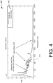
- FIG. 4 illustrates an example spectral graph 400 representing the acoustic data collected by the leak detection sensor 104 at the sampling time.
- the spectral graph 400 may be generated by transforming the acoustic data from the time domain to the frequency domain via Fourier transform, and analyzed by the leak detection sensor 104 or by the controller unit 102.
- the spectral graph 400 shows an example comparison of a baseline spectral pattern 402 with no leak (solid line) to a current spectral pattern with a leak signal where the difference indicates a leak signal 404 (dotted line).
- the baseline spectral pattern 402 may be averaged over multiple sampling times or over multiple samples from the leak detection sensors 104 at the same sampling time.
- the spectral graph 400 includes a legend 406, a vertical axis 408 indicating an acoustic amplitude, and a horizontal axis 410 indicating an acoustic frequency in Hertz (Hz).
- the difference between the current spectral pattern and the baseline spectral pattern 402 is determined and/or calculated by taking an integral of a difference between the current spectral pattern and the baseline spectral pattern 402. In other words, sum areas of the current spectral pattern and the baseline spectral pattern 402 may be subtracted from one another to determine the difference. Additionally, or alternatively, overall shapes of waveforms corresponding to the current spectral pattern and the baseline spectral pattern 402 may be compared to one another to determine this difference, which may be referred to as a correlation.
- the difference between the current spectral pattern and the baseline spectral pattern 402 may be determined by quantifying a maximum numerical difference in amplitude.
- the maximum difference at a certain frequency between the current spectral pattern and the baseline spectral pattern 402 may be selected to determine a leak condition, for example.
- At least one peak and/or characteristic shape of the current spectral pattern may be tracked as it shifts over time (e.g., while generally retaining aspects of its characteristic waveform) and this shift may also be considered when comparing the current spectral pattern to the baseline spectral pattern 402.
- spectral tracking can be effective at tracking peak and/or waveform shifts based on edges of the current spectral pattern that are clearly defined in the frequency domain.
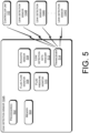
- FIG. 5 illustrates an example block diagram of a leak detection sensor 104A as an example of the leak detection sensors 104.
- the leak detection sensor 104A may be attached to the pipes 108 as discussed with reference to FIG. 1 .
- the leak detection sensor 104A may comprise one or more processors (processors) 502 communicatively coupled to memory 504.
- the processors 502 may include one or more central processing units (CPUs), graphics processing units (GPUs), both CPUs and GPUs, or other processing units or components known in the art.
- the processors 502 may execute computer-executable instructions stored in the memory 504 to perform functions or operations with one or more of components communicatively coupled to the one or more processors 502 and the memory 504 as described above with reference to FIGs. 1-4 .
- the memory 504 may be volatile, such as RAM, non-volatile, such as ROM, flash memory, miniature hard drive, memory card, and the like, or some combination thereof.
- the memory 504 may store computer-executable instructions that are executable by the processors 502.
- the leak detection sensor 104A may monitor leak detection information in the pipes 108, such as the flow of the fluid via the fluid flow monitor 506, the pressure of the fluid via the fluid pressure monitor 510, and the leak detection data via the acoustic sensor 508, at its corresponding location 106 over a time interval, such as a 24-hour period.
- the leak detection data manager 512 may determine the sampling time based at least in part on the monitored flow of the fluid by the fluid flow monitor 506 and/or the monitored pressure of the fluid by the fluid pressure monitor 510.
- the leak detection sensor 104A may collect and store the leak detection information locally in the memory 504 and analyze the leak detection data.
- the leak detection data manager 512 may then determine the sampling time to be when the monitored flow is at a minimum during the time interval, or when the monitored pressure is at a maximum during the time interval. Additionally, the leak detection data manager 512 may perform spectral analysis of the leak detection data and generate a spectral analysis result.
- the leak detection sensor 104A may further comprise a transceiver 514 for establishing a communication with one or more other leak detection sensors or with the controller unit 102.
- the transceiver 514 may transmit the leak detection data, which may include the acoustic data, spectral representation of the acoustic data, and the spectral analysis result, to a controller unit 102 or to one or more other leak detection sensors 104 (the leak detection sensors 104B-104G are shown in this example).
- the leak detection data may be communicated among the leak detection sensors 104 as shown in FIG. 1 and analyzed via distributed intelligence or edge computing at one or more of the leak detection sensors 104. Alternatively, the leak detection data may be transmitted from each leak detection sensor 104 to the controller unit 102 for the analysis.
- the transceiver may communicate with the one or more other leak detection sensors 104, exchange the respective monitored flow of the fluid in the pipes 108, and the leak detection data manager 512 may determine a common sampling time for all or a sub-group of the leak detection sensors 104.
- the processors 502 via distributed intelligence or edge computing at one or more of the leak detection sensors 104, or the controller unit 102, may then determine a leak location based on the spectral analysis, the topology of the pipes 108, and leak detection sensor locations 106.
- FIG. 6 illustrates an example block diagram of a controller unit 102.
- the controller unit 102 may comprise one or more processors (processors) 602 communicatively coupled to memory 604.
- the processors 602 may include one or more central processing units (CPUs), graphics processing units (GPUs), both CPUs and GPUs, or other processing units or components known in the art.
- the processors 602 may execute computer-executable instructions stored in the memory 604 to perform functions or operations with one or more of components communicatively coupled to the one or more processors 602 and the memory 604 as described above with reference to FIGs. 1-4 .
- the memory 604 may be volatile, such as RAM, non-volatile, such as ROM, flash memory, miniature hard drive, memory card, and the like, or some combination thereof.
- the memory 604 may store computer-executable instructions that are executable by the processors 602.
- the controller 102 may comprise a transceiver 606 for receiving the leak detection information from one or more leak detection sensors 104 and a sampling time module for determining the sampling time based on the leak detection data.
- the controller unit 102 that is a sampling time processor 608 of the controller unit 102, may determine, or coordinate, the individual sampling time for each leak detection sensor, the common sampling time for a group of leak detection sensors, or one or more sampling times for one or more subgroups of the group of leak detection sensors based on the topology and leak detection sensor locations.
- the received leak detection information and the sampling time(s) may be in the memory 604.
- the sampling time(s) may then be communicated with, or transmitted to, via the transceiver 606, to the leak detection sensors 104.
- the controller unit 102 may further comprise a leak detection data analyzer 610 for analyzing the leak detection data received from the leak detection sensors 104.
- the leak detection data analyzer 610 may analyze the leak detection data, such as acoustic data collected at the sampling time, by converting the acoustic data in the time domain to frequency domain data, via Fourier transform for example, to produce corresponding spectral representation and performing spectral analysis of the spectral representation to identify a noise and/or leak signature.
- the leak detection data analyzer may then determine a leak location based on the spectral analysis, the topology of the pipes 108, and leak detection sensor locations 106.
- the controller unit 102 may further comprise a communication module 612 allowing the controller unit 102 to communicate with other device(s), system(s), a central office, and/or a user working with the controller unit 102, collectively shown as an entity 614 over a network 616.
- the controller unit 102 via the communication module 612, may communicate the leak location to a utility worker trouble-shooting the pipes 108 for a leak.
- the network 616 may include the Internet, wired media such as a wired network or direct-wired connections, and wireless media such as acoustic, radio frequency (RF), infrared, cellular networks, and other wireless media.
- RF radio frequency
- Computer-readable instructions include routines, applications, application modules, program modules, programs, components, data structures, algorithms, and the like.
- Computer-readable instructions can be implemented on various system configurations, including single-processor or multiprocessor systems, minicomputers, mainframe computers, personal computers, hand-held computing devices, microprocessor-based, programmable consumer electronics, combinations thereof, and the like.
- the computer-readable storage media may include volatile memory (such as random-access memory (RAM)) and/or non-volatile memory (such as read-only memory (ROM), flash memory, etc.).
- volatile memory such as random-access memory (RAM)
- non-volatile memory such as read-only memory (ROM), flash memory, etc.
- the computer-readable storage media may also include additional removable storage and/or non-removable storage including, but not limited to, flash memory, magnetic storage, optical storage, and/or tape storage that may provide non-volatile storage of computer-readable instructions, data structures, program modules, and the like.
- a non-transitory computer-readable storage medium is an example of computer-readable media.
- Computer-readable media includes at least two types of computer-readable media, namely computer-readable storage media and communications media.
- Computer-readable storage media includes volatile and non-volatile, removable and non-removable media implemented in any process or technology for storage of information such as computer-readable instructions, data structures, program modules, or other data.
- Computer-readable storage media includes, but is not limited to, phase change memory (PRAM), static random-access memory (SRAM), dynamic random-access memory (DRAM), other types of random-access memory (RAM), read-only memory (ROM), electrically erasable programmable read-only memory (EEPROM), flash memory or other memory technology, compact disk read-only memory (CD-ROM), digital versatile disks (DVD) or other optical storage, magnetic cassettes, magnetic tape, magnetic disk storage or other magnetic storage devices, or any other non-transmission medium that can be used to store information for access by a computing device.
- communication media may embody computer-readable instructions, data structures, program modules, or other data in a modulated data signal, such as a carrier wave, or other transmission mechanism. As defined herein, computer-readable storage media do not include communication media.
- the computer-readable instructions stored on one or more non-transitory computer-readable storage media when executed by one or more processors, may perform operations described above with reference to FIGs. 1-6 .
- computer-readable instructions include routines, programs, objects, components, data structures, and the like that perform particular functions or implement particular abstract data types.
- the order in which the operations are described is not intended to be construed as a limitation, and any number of the described operations can be combined in any order and/or in parallel to implement the processes.
Landscapes
- Business, Economics & Management (AREA)
- General Physics & Mathematics (AREA)
- Physics & Mathematics (AREA)
- Engineering & Computer Science (AREA)
- Human Resources & Organizations (AREA)
- Economics (AREA)
- Strategic Management (AREA)
- General Business, Economics & Management (AREA)
- Tourism & Hospitality (AREA)
- Health & Medical Sciences (AREA)
- Theoretical Computer Science (AREA)
- Marketing (AREA)
- Entrepreneurship & Innovation (AREA)
- Quality & Reliability (AREA)
- Operations Research (AREA)
- Development Economics (AREA)
- Educational Administration (AREA)
- Game Theory and Decision Science (AREA)
- Public Health (AREA)
- Water Supply & Treatment (AREA)
- General Health & Medical Sciences (AREA)
- Primary Health Care (AREA)
- Examining Or Testing Airtightness (AREA)
Abstract
Description
- The present disclosure generally relates to the field of leak detection systems, and more specifically to methods and apparatus for coordinating leak data sampling for improving leak detection accuracy.
- Leaks in water pipes create noise as water leaves the pipe. Some known leak detection systems used in utility distribution systems (e.g. fluid utility distribution systems such as for gas and water) employ leak detection sensors with acoustic sensors that detect noise and/or characteristic sounds, which may be indicative of a potential leak. In particular, these known leak detection sensors are usually coupled to a pipe and/or portion of a fluid delivery system, and utilize parameters, such as amplitude and/or a time-history of acoustic signals or samples to determine a presence of a potential leak. Such leak detection sensors may take acoustic samples which are then sent to a headend application to be combined with samples from other leak detection sensors and analyzed to determine if there is a sound, or an acoustic signature, that is indicative of a leak.
- However, use of these parameters can be inaccurate, and/or the sampled data can be masked, if the acoustic data were sampled during a period of water usage and/or localized noise.
- The detailed description is set forth with reference to the accompanying figures. In the figures, the left-most digit(s) of a reference number identifies the figure in which the reference number first appears. The use of the same reference numbers in different figures indicates similar or identical items or features.
-
FIG. 1 illustrates an example schematic diagram of a leak detection system comprising a controller unit and a plurality of leak detection sensors distributed over a network of pipes. -
FIG. 2 illustrates an example graph of the monitored flow and the monitored pressure by the leak detection sensors over a portion of a predetermined time interval. -
FIG. 3 illustrates an example process for processing leak detection data monitored by the leak detection sensors at the sampling time. -
FIG. 4 illustrates an example spectral graph representing the acoustic data collected by the leak detection sensor at the sampling time. -
FIG. 5 illustrates an example block diagram of a leak detection sensor. -
FIG. 6 illustrates an example block diagram of a controller unit. - A method and apparatus for coordinating leak data sampling for improving leak detection accuracy are disclosed. Some leak detection systems employ leak detectors with acoustic sensors that detect noise and/or characteristic sounds, which may be indicative of a potential leak. However, with these systems, determination of leaks and/or leak patterns can be difficult due to noise present in the system such as external noise, slow drift of leak patterns and/or irregular use (e.g., irregular or highly variable utility system usage).
- These systems may be statically programmed to sample acoustic data at night when water usage and external noise are typically low. However, depending on locations of leak detection sensors of the leak detection system, there may be nearby noise sources with irregular cycles. That is, the noise may not be the lowest at night, such as a sprinkler system watering at night, a construction site active at night, a 24-hour business still operating at night, and the like.
- A leak detection sensor, or an endpoint device, that supports both leak sampling capabilities and consumption recording may monitor presence of a fluid, such as water or gas, in a fluid transporting medium, such as a pipe, hose, flange, faucet, valve, and the like, herein forward referred to as a pipe or pipes, and may monitor or detect acoustic noise when the fluid consumption at a service point it is attached to, i.e., the location where the water or gas is being provided, is at a minimum over a predetermined time interval such as a day, i.e., a 24-hour period. The leak detection sensor may be a single device or comprise a plurality of devices coupled together. The plurality of devices may include, for example, a fluid consumption measuring device, a timer or timing device, an acoustic sensor, a fluid pressure measuring device, and the like, and may be coupled wirelessly or physically via communication wires and/or shared housing(s). Because when the fluid consumption is low, a noise from the fluid flow is reduced, thus making it an ideal time, which may be referred to as a quiet time or a sampling time, to sample acoustic data in the pipe for detecting a potential leak. The sampling time may also be optimized and/or predicted based on a historical flow pattern recorded by the leak detection sensor or by a meter, headend unit, or other devices coupled to the leak detection sensor over a longer period of time such as a week or a month which may be a rolling/running week or month. A diurnal flow pattern may be derived based on the historical flow pattern and utilized to potentially forecast a day of the week for the optimal recording period. Accordingly, the leak detection sensor may determine, and revise as needed, the quiet time, that is when to sample the acoustic data on a daily basis, based on the monitored fluid flow. The monitored flow includes a monitored quantity of the fluid and a flow rate of the fluid, which may be used interchangeably. In addition, the leak detection sensor may also monitor fluid pressure in the pipe at the service point. The sampling time may include one or more sampling times within a time interval if appropriate. Because the fluid pressure is generally known to be at the highest when the fluid flow is at its lowest, the fluid pressure data may also be used in determining the quite time.
- While an externally powered leak detection sensor, such as one powered by an external power supply connected to an AC outlet, may continuously monitor the fluid flow, the fluid pressure, and the acoustic data, a battery-powered leak detection sensor may, instead, monitor the fluid flow, the fluid pressure, and the acoustic data periodically, for example, every five minutes for a monitoring period of five seconds, over the 24-hour period to conserve the battery power. However, for an urgent situation, such as a newly suspected leak, running diagnostics, or inspecting local pipes, the battery-powered leak detection sensor may also be controlled to continuously monitor the fluid flow, the fluid pressure, and the acoustic data for a certain period of time.
- For example, a group of leak detection sensors for water may be attached to a network of water pipes in a given area, and each leak detection sensor may monitor the water flow, the water pressure, and the acoustic data over a day to determine a respective sampling time based on when a respective monitored water flow is at the lowest and/or a respective monitored pressure is at the highest during the day. Topology of the network of water pipes and a location of each leak detection sensor on the water pipes may be recorded and used in determining a leak location. Each leak detection sensor may then determine its own daily sampling time individually. Alternatively, monitored water flow and pressure data may be communicated among the group of leak detection sensors and analyzed via distributed intelligence or edge computing at one or more of the leak detection sensors to determine, or coordinate, an individual sampling time for each leak detection sensor, a common sampling time for the group of leak detection sensors, or one or more sampling times for one or more subgroups of the group of leak detection sensors based on the topology and leak detection sensor locations.
- Alternatively, a controller unit, or a headend device, may receive and analyze monitored water flow and pressure data from the group of leak detection sensors and determine, or coordinate, the individual sampling time for each leak detection sensor, the common sampling time for the group of leak detection sensors, or one or more sampling times for one or more subgroups of the group of leak detection sensors based on the topology and leak detection sensor locations.
- In addition to sampling the acoustic data at the sampling time, the leak detection sensor may also sample acoustic data at a time offset by a predetermined offset time interval from the sampling time comparison to avoid unexpected noise. The sampling time may also be re-determined and adjusted periodically to account for changes in water, or gas, usage patterns based on the day of the week, ex., a weekday vs. weekend, local changes, such as residential turn-over, new constructions, and seasonal changes, such as a sprinkler usage. Because acoustic information collected by the leak detection sensor may be affected by its environment and conditions, the leak detection sensor may be calibrated based on a material of the pipe, such as copper and PVC, a location, such as a distance from other leak detection sensors of the group and/or a distance from a consumption point, and an expected fluid pressure. Additionally, if a leak detection sensor detects a noise in a given time period outside of the sampling time, that leak detection sensor may signal the other leak detection sensors to sample the acoustic data to determine if the noise is local or regional.
- At the sampling time, the leak detection sensor may record acoustic data present in the pipe, analyze the acoustic data by performing spectral analysis on the acoustic data, and identify a noise and/or leak signature. Examples of the spectral analysis include methods described in
US Patent Numbers 10,359,335 10,551,274 10,704,982 US Patent Application Publication Number 2019/0154535 , entireties of which are herein incorporated by reference. - Alternatively, the acoustic data may be communicated among the group of leak detection sensors and analyzed via distributed intelligence or edge computing at one or more of the leak detection sensors to determine a leak location, or be transmitted from each leak detection sensor to the controller unit for analysis to determine the leak location based on the topology of the pipes and leak detection sensor locations. The leak location includes a pre-localized leak location. For example, if a leak detection sensor records a leak, i.e., a loud acoustic signal indicative of a leak, then a location of the leak may be estimated to be near the location of the leak detection sensor, that is, the pre-localized leak location. Based on the acoustic signal indicative of the same leak by nearby leak detection sensors, the leak location may be determined by triangulating based on the locations of the leak detection location and the topology of the pipe network. The leak detection sensors may be calibrated such that if a signal, from a location having the same distance to two leak detection sensors, was captured by the two leak detection sensors, both leak detection sensors would record the signal with equal amplitude. Cross correlation may also be performed based on a time synchronized data, i.e., captured acoustic signal.
-
FIG. 1 illustrates an example schematic diagram of aleak detection system 100 comprising acontroller unit 102 and a plurality of leak detection sensors 104 distributed at multiple locations 106 over a network ofpipes 108. In this example, seven leak detection sensors, 104A-104G, are shown to be attached to various locations, 106A-106G, of the network ofpipes 108. In general, a leak detection sensor 104 may refer to a single leak detection sensor or one or more leak detection sensors. - A leak detection sensor 104 may monitor leak detection information, such as the flow and the pressure of the fluid and leak detection data, in the
pipes 108 at its corresponding location 106 over a time interval, which may be predetermined such as a 24-hour period, and manage the leak detection data monitored at a sampling time where the sampling time may be determined based at least in part on the monitored flow and/or pressure. For example, each leak detection sensor 104 may collect and store the leak detection information locally and analyze the leak detection data. As shown with dotted lines, the leak detection sensors 104 may also communicate with each other and coordinate to manage the leak detection information and the sampling time. In addition, or alternatively, the leak detection sensors 104 may communicate with thecontroller unit 102 to have thecontroller unit 102 manage the leak detection information and the sampling time. -
FIG. 2 illustrates anexample graph 200 of the monitoredflow 202 and the monitoredpressure 204 by the leak detection sensors 104 over a portion, from time 0:00 to 6:00 AM, of the predetermined time interval. - The graphs of monitored flow 202 (A-G) show that the monitored flow of each leak detection sensor 104 is the lowest at 3:00 AM, as indicated as a solid-
line circle 206, and the graphs of monitored pressure 204 (α-γ) show that the monitored pressure of each leak detection sensor 104 is the highest at 3:00 AM, as indicated by a dotted-line circle 208. As discussed above, the sampling time may be set to when the fluid consumption is the lowest because the noise from the fluid flow is reduced and/or minimized, in this example 3:00 AM as indicated by the solid-line circle 206. Additionally, the monitoredpressure 204 of the fluid may also be utilized in determining and setting the sampling time because the fluid pressure is generally known to be at the highest when the fluid flow is at the lowest. In this example, the highest pressure for the leak detection sensors 104 also occurs at 3:00 AM as indicated by the dotted-line circle 208. However, the sampling time may not be the same time for all of the leak detection sensors 104 based on the occurrence of the minimum flow at different times for different leak detection sensors. -
FIG. 3 illustrates anexample process 300 for processing leak detection data monitored by the leak detection sensors 104 at the sampling time. - At
block 302, a leak detection sensor 104 may be monitoring leak detection information associated with a fluid, such as water or gas, in thepipes 108 over a time interval, which may be predetermined or dynamically determined, at a corresponding location 106 of the leak detection sensor 104 as shown inFIG. 1 . In this example, water as the fluid is used to describe the process. The leak detection information may comprise a flow rate of the water and leak detection data associated with the water. In addition, a pressure of the water may also be monitored and included in the leak detection information. For example, when the leak detection sensors 104 are initially activated, the leak detection information from each leak detection sensor 104 may be collected over a time interval, such as a day, several days, a week, or other desired and appropriate period of time. The leak detection information may be collected and stored individually by the leak detection sensors 104, collected, stored, and distributed among the leak detection sensors 104, or collected by thecontroller unit 102 as described with reference toFIG. 1 . - While an externally powered leak detection sensor, such as one powered by an external power supply connected to an AC outlet, may continuously monitor and collect the leak detection information, a battery-powered leak detection sensor may, instead, monitor and collect the leak detection information periodically, for example, every five minutes for a monitoring period of five seconds, over the 24-hour period to conserve the battery power.
- At
block 304, a sampling time may be determined based on the monitored flow rate and/or the monitored pressure of the water. For example, as discussed above with reference toFIG. 2 , the sampling time may be determined to be when the monitored flow rate is at a minimum during the time interval because individual leak detection sensors will always have a respective minimum flow rate. For a group of a plurality of leak detection sensors, the sampling time may also be selected based on a threshold flow rate below which the flow rate is considered to be sufficiently low. For a large group of a plurality of leak detection sensors, it would be unlikely that all leak detection sensors of the group individually measure the minimum flow rate at the same time. Therefore, when or if an average flow rate associated with the group of the plurality of leak detection sensors were below a threshold flow rate, it could be determined as an appropriate time to sample. By using the threshold flow rate, it would allow determining a coordinated sample time even when a leak detection sensor of the group were measuring the maximum amount of flow rate at that moment. - Alternatively, the sampling time may be determined to be when the monitored pressure is at a maximum during the time interval or when the monitored pressure is higher than a threshold pressure, which may or may not coincide with the monitored minimum flow rate. The pressure at specific locations may be determined based on hydraulic modeling solution. With the hydraulic model over a specific geographical area of the pipe network calibrated, the pressure throughout the specific geographical area of the pipe network at multiple locations over the 24 hour period may be predicted.
- In some examples, a sampling time may be selected based on some combination of flow rate and pressure. For instance, leak detection data may be sampled at a time when the flow rate is relatively low, but not at the minimum, and the pressure is relatively high, but not at the maximum. While the sampling time may be ideally when the flow rate is at the minimum and the pressure is at the maximum, the sampling time may also be determined based on the population of the leak detection sensors and their consumption patterns. For example, if some leak detection sensors were known to hear at a certain period a consumption noise that likely is a leak, the results may be weighed. For a given area, if one leak detection sensor (local leak detection sensor) makes its recordings at the quietest time and other surrounding leak detection sensors make their recordings at some other quiet time, the spectral signatures of all the leak detection sensors may analyzed to determine whether a stationary signal, or a common spectral pattern, exists that is detected by the local and surrounding leak detection sensors. This would enhance the confidence that a leak is present.
- For example, when the leak detection sensors 104 are initially activated, the leak detection information from each leak detection sensor 104 may be collected over the time interval, such as a day, several days, a week, or other desired and appropriate period of time. The leak detection information may be collected and stored individually by the leak detection sensors 104, collected, stored, and distributed among the leak detection sensors 104, or collected and stored by the
controller unit 102 as described with reference toFIG. 1 . Additionally, the time interval, for example, a 24-hour period, may be repeated periodically to revise the sampling time as needed or desired, and the sampling time may include one or more sampling times within the time interval if appropriate. The leak detection sensor 104 may also sample the leak detection data at a time offset by a predetermined offset time interval from the sampling time for comparing the leak detection data. As discussed with reference toFIG. 1 , the sampling time may be determined by each leak detection sensor 104 individually based on respective leak detection information, by coordinating among the leak detection sensors 104 based on leak detection information from some or all of the leak detection sensors 104, or by thecontroller unit 102 based on leak detection information from some or all of the leak detection sensors 104. The sampling time may be determined to be a common sampling time for the leak detection sensors 104. - Once the sampling time is determined, the leak detection sensors 104 may manage the leak detection data corresponding to the sampling time at
block 306. For example, an individual leak detection sensor 104 may analyze the leak detection data, such as acoustic data collected at the sampling time, by converting the acoustic data in the time domain to frequency domain data, via Fourier transform for example, to produce corresponding spectral representation and performing spectral analysis of the spectral representation to identify a noise and/or leak signature. Alternatively, the acoustic data may be communicated among the leak detection sensors 104 and analyzed via distributed intelligence or edge computing at one or more of the leak detection sensors 104 or be transmitted from each leak detection sensor 104 to thecontroller unit 102 for the analysis. Atblock 308, the leak detection sensors 104, via distributed intelligence or edge computing at one or more of the leak detection sensors 104, or thecontroller unit 102, may determine the leak location based on the spectral analysis, the topology of thepipes 108, and leak detection sensor locations 106. -
FIG. 4 illustrates an examplespectral graph 400 representing the acoustic data collected by the leak detection sensor 104 at the sampling time. As discussed above, thespectral graph 400 may be generated by transforming the acoustic data from the time domain to the frequency domain via Fourier transform, and analyzed by the leak detection sensor 104 or by thecontroller unit 102. Thespectral graph 400 shows an example comparison of a baselinespectral pattern 402 with no leak (solid line) to a current spectral pattern with a leak signal where the difference indicates a leak signal 404 (dotted line). The baselinespectral pattern 402 may be averaged over multiple sampling times or over multiple samples from the leak detection sensors 104 at the same sampling time. Thespectral graph 400 includes alegend 406, avertical axis 408 indicating an acoustic amplitude, and ahorizontal axis 410 indicating an acoustic frequency in Hertz (Hz). - In some examples, the difference between the current spectral pattern and the baseline
spectral pattern 402 is determined and/or calculated by taking an integral of a difference between the current spectral pattern and the baselinespectral pattern 402. In other words, sum areas of the current spectral pattern and the baselinespectral pattern 402 may be subtracted from one another to determine the difference. Additionally, or alternatively, overall shapes of waveforms corresponding to the current spectral pattern and the baselinespectral pattern 402 may be compared to one another to determine this difference, which may be referred to as a correlation. - In some examples, the difference between the current spectral pattern and the baseline
spectral pattern 402 may be determined by quantifying a maximum numerical difference in amplitude. In particular, the maximum difference at a certain frequency between the current spectral pattern and the baselinespectral pattern 402 may be selected to determine a leak condition, for example. - Additionally, or alternatively, at least one peak and/or characteristic shape of the current spectral pattern, for example, the
leak signal 404, may be tracked as it shifts over time (e.g., while generally retaining aspects of its characteristic waveform) and this shift may also be considered when comparing the current spectral pattern to the baselinespectral pattern 402. In such examples, spectral tracking can be effective at tracking peak and/or waveform shifts based on edges of the current spectral pattern that are clearly defined in the frequency domain. -
FIG. 5 illustrates an example block diagram of aleak detection sensor 104A as an example of the leak detection sensors 104. - The
leak detection sensor 104A may be attached to thepipes 108 as discussed with reference toFIG. 1 . Theleak detection sensor 104A may comprise one or more processors (processors) 502 communicatively coupled tomemory 504. Theprocessors 502 may include one or more central processing units (CPUs), graphics processing units (GPUs), both CPUs and GPUs, or other processing units or components known in the art. Theprocessors 502 may execute computer-executable instructions stored in thememory 504 to perform functions or operations with one or more of components communicatively coupled to the one ormore processors 502 and thememory 504 as described above with reference toFIGs. 1-4 . Depending on the exact configuration of theleak detection sensor 104A, thememory 504 may be volatile, such as RAM, non-volatile, such as ROM, flash memory, miniature hard drive, memory card, and the like, or some combination thereof. Thememory 504 may store computer-executable instructions that are executable by theprocessors 502. - A fluid flow monitor 506 for monitoring flow of the fluid in the
pipes 108, anacoustic sensor 508 for monitoring leak detection data associated with the fluid in thepipes 108, a fluid pressure monitor 510 for monitoring pressure of the fluid in thepipes 108, and a leakdetection data manager 512 for processing the leak detection data monitored at a sampling time. - As discussed above, with reference to
FIGs. 1-3 , theleak detection sensor 104A may monitor leak detection information in thepipes 108, such as the flow of the fluid via the fluid flow monitor 506, the pressure of the fluid via the fluid pressure monitor 510, and the leak detection data via theacoustic sensor 508, at its corresponding location 106 over a time interval, such as a 24-hour period. The leakdetection data manager 512 may determine the sampling time based at least in part on the monitored flow of the fluid by the fluid flow monitor 506 and/or the monitored pressure of the fluid by thefluid pressure monitor 510. For example, theleak detection sensor 104A may collect and store the leak detection information locally in thememory 504 and analyze the leak detection data. The leakdetection data manager 512 may then determine the sampling time to be when the monitored flow is at a minimum during the time interval, or when the monitored pressure is at a maximum during the time interval. Additionally, the leakdetection data manager 512 may perform spectral analysis of the leak detection data and generate a spectral analysis result. - The
leak detection sensor 104A may further comprise atransceiver 514 for establishing a communication with one or more other leak detection sensors or with thecontroller unit 102. Thetransceiver 514 may transmit the leak detection data, which may include the acoustic data, spectral representation of the acoustic data, and the spectral analysis result, to acontroller unit 102 or to one or more other leak detection sensors 104 (theleak detection sensors 104B-104G are shown in this example). The leak detection data may be communicated among the leak detection sensors 104 as shown inFIG. 1 and analyzed via distributed intelligence or edge computing at one or more of the leak detection sensors 104. Alternatively, the leak detection data may be transmitted from each leak detection sensor 104 to thecontroller unit 102 for the analysis. Additionally, the transceiver may communicate with the one or more other leak detection sensors 104, exchange the respective monitored flow of the fluid in thepipes 108, and the leakdetection data manager 512 may determine a common sampling time for all or a sub-group of the leak detection sensors 104. - The
processors 502, via distributed intelligence or edge computing at one or more of the leak detection sensors 104, or thecontroller unit 102, may then determine a leak location based on the spectral analysis, the topology of thepipes 108, and leak detection sensor locations 106. -
FIG. 6 illustrates an example block diagram of acontroller unit 102. - The
controller unit 102 may comprise one or more processors (processors) 602 communicatively coupled tomemory 604. Theprocessors 602 may include one or more central processing units (CPUs), graphics processing units (GPUs), both CPUs and GPUs, or other processing units or components known in the art. Theprocessors 602 may execute computer-executable instructions stored in thememory 604 to perform functions or operations with one or more of components communicatively coupled to the one ormore processors 602 and thememory 604 as described above with reference toFIGs. 1-4 . Depending on the exact configuration of thecontroller unit 102, thememory 604 may be volatile, such as RAM, non-volatile, such as ROM, flash memory, miniature hard drive, memory card, and the like, or some combination thereof. Thememory 604 may store computer-executable instructions that are executable by theprocessors 602. - The
controller 102 may comprise atransceiver 606 for receiving the leak detection information from one or more leak detection sensors 104 and a sampling time module for determining the sampling time based on the leak detection data. As described above with reference toFIG. 1-3 and5 , thecontroller unit 102, that is asampling time processor 608 of thecontroller unit 102, may determine, or coordinate, the individual sampling time for each leak detection sensor, the common sampling time for a group of leak detection sensors, or one or more sampling times for one or more subgroups of the group of leak detection sensors based on the topology and leak detection sensor locations. The received leak detection information and the sampling time(s) may be in thememory 604. The sampling time(s) may then be communicated with, or transmitted to, via thetransceiver 606, to the leak detection sensors 104. - The
controller unit 102 may further comprise a leak detection data analyzer 610 for analyzing the leak detection data received from the leak detection sensors 104. The leak detection data analyzer 610 may analyze the leak detection data, such as acoustic data collected at the sampling time, by converting the acoustic data in the time domain to frequency domain data, via Fourier transform for example, to produce corresponding spectral representation and performing spectral analysis of the spectral representation to identify a noise and/or leak signature. The leak detection data analyzer may then determine a leak location based on the spectral analysis, the topology of thepipes 108, and leak detection sensor locations 106. - The
controller unit 102 may further comprise acommunication module 612 allowing thecontroller unit 102 to communicate with other device(s), system(s), a central office, and/or a user working with thecontroller unit 102, collectively shown as anentity 614 over anetwork 616. For example, thecontroller unit 102, via thecommunication module 612, may communicate the leak location to a utility worker trouble-shooting thepipes 108 for a leak. Thenetwork 616 may include the Internet, wired media such as a wired network or direct-wired connections, and wireless media such as acoustic, radio frequency (RF), infrared, cellular networks, and other wireless media. - Some or all operations of the methods described above can be performed by execution of computer-readable instructions stored on a computer-readable storage medium, as defined below. The term "computer-readable instructions" as used in the description and claims, include routines, applications, application modules, program modules, programs, components, data structures, algorithms, and the like. Computer-readable instructions can be implemented on various system configurations, including single-processor or multiprocessor systems, minicomputers, mainframe computers, personal computers, hand-held computing devices, microprocessor-based, programmable consumer electronics, combinations thereof, and the like.
- The computer-readable storage media may include volatile memory (such as random-access memory (RAM)) and/or non-volatile memory (such as read-only memory (ROM), flash memory, etc.). The computer-readable storage media may also include additional removable storage and/or non-removable storage including, but not limited to, flash memory, magnetic storage, optical storage, and/or tape storage that may provide non-volatile storage of computer-readable instructions, data structures, program modules, and the like.
- A non-transitory computer-readable storage medium is an example of computer-readable media. Computer-readable media includes at least two types of computer-readable media, namely computer-readable storage media and communications media. Computer-readable storage media includes volatile and non-volatile, removable and non-removable media implemented in any process or technology for storage of information such as computer-readable instructions, data structures, program modules, or other data. Computer-readable storage media includes, but is not limited to, phase change memory (PRAM), static random-access memory (SRAM), dynamic random-access memory (DRAM), other types of random-access memory (RAM), read-only memory (ROM), electrically erasable programmable read-only memory (EEPROM), flash memory or other memory technology, compact disk read-only memory (CD-ROM), digital versatile disks (DVD) or other optical storage, magnetic cassettes, magnetic tape, magnetic disk storage or other magnetic storage devices, or any other non-transmission medium that can be used to store information for access by a computing device. In contrast, communication media may embody computer-readable instructions, data structures, program modules, or other data in a modulated data signal, such as a carrier wave, or other transmission mechanism. As defined herein, computer-readable storage media do not include communication media.
- The computer-readable instructions stored on one or more non-transitory computer-readable storage media, when executed by one or more processors, may perform operations described above with reference to
FIGs. 1-6 . Generally, computer-readable instructions include routines, programs, objects, components, data structures, and the like that perform particular functions or implement particular abstract data types. The order in which the operations are described is not intended to be construed as a limitation, and any number of the described operations can be combined in any order and/or in parallel to implement the processes. - Although the subject matter has been described in language specific to structural features and/or methodological acts, it is to be understood that the subject matter defined in the appended claims is not necessarily limited to the specific features or acts described. Rather, the specific features and acts are disclosed as exemplary forms of implementing the claims.
Claims (15)
- A method performed by a leak detection sensor, the method comprising:monitoring leak detection information associated with a fluid in a fluid transporting medium over a time interval, the leak detection information comprising:a monitored flow of the fluid in the fluid transporting medium, andleak detection data associated with the fluid in the fluid transporting medium; andprocessing the leak detection data monitored at a sampling time in the time interval to identify leaks in the fluid transporting medium, the sampling time determined based at least in part on the monitored flow of the fluid.
- The method of claim 1, wherein the leak detection sensor is coupled to the fluid transporting medium.
- The method of claim 1, wherein the sampling time includes an offset sampling time offset by a predetermined offset time interval from the sampling time initially determined based at least in part on the monitoring.
- The method of any preceding claim, wherein processing the leak detection data comprises:performing spectral analysis of the leak detection data; andgenerating, based at least in part on a spectral analysis result, an indication of a leak in the fluid transporting medium.
- The method of any preceding claim, wherein the leak detection sensor is one of a plurality of leak detection sensors, and
the method further comprising:
receiving, from one or more other leak detection sensors of the plurality of leak detection sensors, respective leak detection information at a respective sampling time based at least in part on a respective monitored pressure and a respective monitored flow over the time interval. - The method of claim 5, wherein determining the respective sampling time includes:coordinating among the plurality of leak detection sensors; anddetermining a common sampling time for the plurality of leak detection sensors.
- The method of claim 5, wherein determining the respective sampling time includes:selecting a group of leak detection sensors from the plurality of leak detection sensors; anddetermining a common sampling time for the group of leak detection sensors from the plurality of leak detection sensors.
- The method of claim 5, further comprising:
performing spectral analysis of the respective leak detection information at the respective sampling time; and
determining, based at least in part on the spectral analysis, a location of a leak; and optionally wherein the location of the leak is determined based at least in part on a respective spectral analysis result, a topology of the fluid transporting medium, and a respective location of each leak detection sensor of the plurality of leak detection sensors. - A leak detection sensor comprising:one or more processors; andmemory communicatively coupled to the one or more processors, the memory storing thereon computer executable instructions that, when executed by the one or more processors, cause the leak detection sensor to perform operations comprising:monitoring leak detection information associated with a fluid in a fluid transporting medium over a time interval, the leak detection information comprising:a monitored flow of the fluid in the fluid transporting medium, andleak detection data associated with the fluid in the fluid transporting medium; andprocessing the leak detection data monitored at a sampling time in the time interval to identify leaks in the fluid transporting medium, the sampling time determined based at least in part on the monitored flow of the fluid,wherein the leak detection sensor is configured to be attached to the fluid transporting medium.
- The leak detection sensor of claim 9, wherein processing the leak detection data comprises:performing spectral analysis of the leak detection data, andgenerating, based at least in part on a spectral analysis result, an indication of a leak in the fluid transporting medium.
- The leak detection sensor of claim 9 or 10 wherein the leak detection sensor is one of a plurality of leak detection sensors, and
the operations further comprise:
receiving, from one or more other leak detection sensors of the plurality of leak detection sensors, respective leak detection information at a respective sampling time based at least in part on a respective monitored pressure and a respective monitored flow over the time interval. - The leak detection sensor of claim 11, wherein the operations further comprise:performing spectral analysis of the respective leak detection information at the respective sampling time; anddetermining, based at least in part on the spectral analysis, a location of a leak; and optionally wherein the location of the leak is determined based at least in part on a respective spectral analysis result, a topology of the fluid transporting medium, and a respective location of each leak detection sensor of the plurality of leak detection sensors.
- A method performed by a controller unit, the method comprising:receiving, from a plurality of leak detection sensors, respective monitored leak detection information associated with a fluid in a fluid transporting medium over a time interval, the respective leak detection information comprising:a respective monitored flow of the fluid in the fluid transporting medium, andrespective leak detection data associated with the fluid in the fluid transporting medium;processing the respective leak detection data monitored at a sampling time in the time interval to identify leaks in the fluid transporting medium, the sampling time determined based at least in part on the monitored flow of the fluid.
- The leak detection sensor of claim 9 or the method of claim 1 or claim 13, wherein:the leak detection information further comprises a monitored pressure of the fluid in the fluid transporting medium, andthe sampling time is determined based on at least one of:a time when the monitored flow is at a minimum or below a threshold flow during the time interval, ora time when the monitored pressure is at a maximum or above a threshold pressure during the time interval.
- The method of claim 13 or 14, further comprising:performing spectral analysis of the respective leak detection information at the respective sampling time; anddetermining, based at least in part on the spectral analysis, a location of a leak; and optionallywherein the location of the leak is determined based at least in part on a respective spectral analysis result, a topology of the fluid transporting medium, and a respective location of each leak detection sensor of the plurality of leak detection sensors.
Applications Claiming Priority (1)
| Application Number | Priority Date | Filing Date | Title |
|---|---|---|---|
| US17/497,493 US11788919B2 (en) | 2021-10-08 | 2021-10-08 | Coordinated acoustic leak detection sensor sampling |
Publications (2)
| Publication Number | Publication Date |
|---|---|
| EP4163615A1 true EP4163615A1 (en) | 2023-04-12 |
| EP4163615B1 EP4163615B1 (en) | 2025-11-05 |
Family
ID=83693101
Family Applications (1)
| Application Number | Title | Priority Date | Filing Date |
|---|---|---|---|
| EP22197944.6A Active EP4163615B1 (en) | 2021-10-08 | 2022-09-27 | Coordinated acoustic leak detection sensor sampling |
Country Status (4)
| Country | Link |
|---|---|
| US (1) | US11788919B2 (en) |
| EP (1) | EP4163615B1 (en) |
| AU (1) | AU2022231736A1 (en) |
| CA (1) | CA3171528C (en) |
Cited By (1)
| Publication number | Priority date | Publication date | Assignee | Title |
|---|---|---|---|---|
| WO2024251341A1 (en) * | 2023-06-05 | 2024-12-12 | Siemens Aktiengesellschaft | System and method of communication for acoustic leak detection sensors |
Families Citing this family (2)
| Publication number | Priority date | Publication date | Assignee | Title |
|---|---|---|---|---|
| FR3109214B1 (en) * | 2020-04-09 | 2022-09-02 | Sagemcom Energy & Telecom Sas | Method for detecting and locating a fluid leak |
| US20230401654A1 (en) * | 2022-06-10 | 2023-12-14 | Badger Meter, Inc. | System and Method for Identifying Water Usage Violations in Streamed Data |
Citations (6)
| Publication number | Priority date | Publication date | Assignee | Title |
|---|---|---|---|---|
| US20120007743A1 (en) * | 2009-11-16 | 2012-01-12 | Aquarius Spectrum Ltd. | System method and device for leak detection and localization in a pipe network |
| US20170307466A1 (en) * | 2016-04-21 | 2017-10-26 | Neptune Technology Group Inc. | Ultrasonic Flow Meter Leak Detection System and Method |
| EP2929300B1 (en) * | 2012-12-04 | 2019-02-20 | Stephen J. Horne | Fluid flow detection and analysis device and system |
| US20190154535A1 (en) | 2017-11-21 | 2019-05-23 | Itron, Inc. | Methods and apparatus to detect leaks based on temperature data |
| US10359335B2 (en) | 2017-03-03 | 2019-07-23 | Itron, Inc. | Methods and apparatus to analyze recordings in leak detection |
| US10551274B2 (en) | 2017-11-09 | 2020-02-04 | Itron, Inc. | Methods and apparatus to detect leaks |
Family Cites Families (33)
| Publication number | Priority date | Publication date | Assignee | Title |
|---|---|---|---|---|
| GB2209218B (en) | 1987-08-28 | 1991-05-15 | Gen Electric Co Plc | Flow-meter for sensing the velocity of flow of a fluid |
| US5038614A (en) | 1989-08-10 | 1991-08-13 | Atlantic Richfield Company | Acoustic vibration detection of fluid leakage from conduits |
| US7949495B2 (en) | 1996-03-28 | 2011-05-24 | Rosemount, Inc. | Process variable transmitter with diagnostics |
| US5974862A (en) | 1997-05-06 | 1999-11-02 | Flow Metrix, Inc. | Method for detecting leaks in pipelines |
| US20030204338A1 (en) * | 2002-04-22 | 2003-10-30 | Peter Martinek | Method and measurement probe for the performance of measurements in water supply systems |
| US6567006B1 (en) | 1999-11-19 | 2003-05-20 | Flow Metrix, Inc. | Monitoring vibrations in a pipeline network |
| GB2358246A (en) | 2000-01-05 | 2001-07-18 | Palmer Environmental Ltd | Determining the position of a signal from a pipe |
| US6453247B1 (en) | 2000-01-14 | 2002-09-17 | National Research Council Of Canada | PC multimedia-based leak detection system for water transmission and distribution pipes |
| US6957157B2 (en) | 2002-11-12 | 2005-10-18 | Flow Metrix, Inc. | Tracking vibrations in a pipeline network |
| CA2416171A1 (en) | 2003-01-13 | 2004-07-13 | Pure Technologies Ltd. | Pipeline monitoring system |
| US7880641B2 (en) | 2006-12-21 | 2011-02-01 | Parris Earl H | Configurable smart utility meter box |
| JP4822990B2 (en) * | 2006-09-07 | 2011-11-24 | 株式会社東芝 | Water leakage monitoring system |
| FR2910619B1 (en) | 2006-12-21 | 2009-05-08 | Cybernetix Sa | SYSTEM FOR DETECTING AND LOCATING AN EVENT IN A FLUID TRANSPORT PIPELINE FOR THE USE OF LOW BANDWIDTH COMMUNICATION MEANS |
| US7705721B1 (en) | 2007-03-13 | 2010-04-27 | Network Appliance, Inc. | Apparatus and method for sensing and responding to environmental conditions of a computer system at non-uniform polling intervals |
| US8643716B1 (en) | 2008-02-13 | 2014-02-04 | Power Survey Llc | Method and system for mobile steam leak detection |
| US7711500B1 (en) | 2008-10-24 | 2010-05-04 | General Electric Company | Pressure relief valve monitoring |
| NO330636B1 (en) | 2009-02-23 | 2011-05-30 | Roxar Flow Measurement As | Device and method for acoustic-based sand monitoring by a rudder system |
| US8346492B2 (en) | 2009-10-21 | 2013-01-01 | Acoustic Systems, Inc. | Integrated acoustic leak detection system using intrusive and non-intrusive sensors |
| EP2686643A4 (en) | 2011-03-18 | 2014-09-10 | Soneter Llc | Methods and apparatus for fluid flow measurement |
| DK177233B1 (en) | 2011-04-07 | 2012-07-30 | Dantaet As | Methods and means for detecting leaks |
| US20150330863A1 (en) | 2011-05-16 | 2015-11-19 | Triple Plus | Method and System for Identifying Leaks in Fluid Pipe Construction |
| US9291520B2 (en) | 2011-08-12 | 2016-03-22 | Mueller International, Llc | Fire hydrant leak detector |
| US20130101127A1 (en) | 2011-10-21 | 2013-04-25 | Research In Motion Limited | System and method for changing an activation state of an electronic device using acoustic signals |
| CN102563361A (en) | 2012-01-18 | 2012-07-11 | 中国石油大学(华东) | Device and method for detecting and positioning leakage of gas transmission pipeline based on conventional data and sound wave signals |
| SG11201503041SA (en) | 2012-10-26 | 2015-05-28 | Mueller Int Llc | Detecting leaks in a fluid distribution system |
| US9500554B2 (en) | 2013-03-28 | 2016-11-22 | Exxonmobil Research And Engineering Company | Method and system for detecting a leak in a pipeline |
| KR101447925B1 (en) | 2013-08-22 | 2014-10-08 | 주식회사 엘지씨엔에스 | Leakage signal analysis method |
| WO2016185435A1 (en) | 2015-05-21 | 2016-11-24 | Saipem S.P.A. | System and method for real time remote measurement of geometric parameters of a pipeline in the launch step, through sound waves |
| US11291413B2 (en) | 2015-12-15 | 2022-04-05 | Mayo Foundation For Medical Education And Research | Systems and methods for linear-time clustering for bounded, repeatable, rare events in physiological signals |
| US10302454B2 (en) * | 2016-02-15 | 2019-05-28 | Olea Networks, Inc. | Retrofit device and method of retrofitting a flow meter |
| US10473270B2 (en) | 2016-09-30 | 2019-11-12 | General Electric Company | Leak detection user interfaces |
| CN114902029B (en) * | 2019-11-26 | 2025-09-19 | 卡姆鲁普股份有限公司 | Fluid consumption meter and leak detection system |
| WO2023030597A1 (en) * | 2021-09-06 | 2023-03-09 | Kamstrup A/S | System and method for acoustic leak detection in a utility distribution system |
-
2021
- 2021-10-08 US US17/497,493 patent/US11788919B2/en active Active
-
2022
- 2022-08-26 CA CA3171528A patent/CA3171528C/en active Active
- 2022-09-15 AU AU2022231736A patent/AU2022231736A1/en active Pending
- 2022-09-27 EP EP22197944.6A patent/EP4163615B1/en active Active
Patent Citations (7)
| Publication number | Priority date | Publication date | Assignee | Title |
|---|---|---|---|---|
| US20120007743A1 (en) * | 2009-11-16 | 2012-01-12 | Aquarius Spectrum Ltd. | System method and device for leak detection and localization in a pipe network |
| EP2929300B1 (en) * | 2012-12-04 | 2019-02-20 | Stephen J. Horne | Fluid flow detection and analysis device and system |
| US20170307466A1 (en) * | 2016-04-21 | 2017-10-26 | Neptune Technology Group Inc. | Ultrasonic Flow Meter Leak Detection System and Method |
| US10359335B2 (en) | 2017-03-03 | 2019-07-23 | Itron, Inc. | Methods and apparatus to analyze recordings in leak detection |
| US10704982B2 (en) | 2017-03-03 | 2020-07-07 | Itron, Inc. | Sensor recording analysis apparatus and method |
| US10551274B2 (en) | 2017-11-09 | 2020-02-04 | Itron, Inc. | Methods and apparatus to detect leaks |
| US20190154535A1 (en) | 2017-11-21 | 2019-05-23 | Itron, Inc. | Methods and apparatus to detect leaks based on temperature data |
Cited By (1)
| Publication number | Priority date | Publication date | Assignee | Title |
|---|---|---|---|---|
| WO2024251341A1 (en) * | 2023-06-05 | 2024-12-12 | Siemens Aktiengesellschaft | System and method of communication for acoustic leak detection sensors |
Also Published As
| Publication number | Publication date |
|---|---|
| CA3171528A1 (en) | 2023-04-08 |
| US11788919B2 (en) | 2023-10-17 |
| US20230111271A1 (en) | 2023-04-13 |
| AU2022231736A1 (en) | 2023-04-27 |
| EP4163615B1 (en) | 2025-11-05 |
| CA3171528C (en) | 2025-05-20 |
Similar Documents
| Publication | Publication Date | Title |
|---|---|---|
| CA3171528C (en) | Coordinated acoustic leak detection sensor sampling | |
| US12235241B2 (en) | Fluid consumption meter with noise sensor | |
| CA2961798C (en) | Ultrasonic flow meter leak detection system and method | |
| US6957157B2 (en) | Tracking vibrations in a pipeline network | |
| US20210293652A1 (en) | Method and device for judging gas leakage, and electronic device | |
| JP5519872B2 (en) | System and method for locating missing nodes in a network | |
| US20180292292A1 (en) | Pipe condition detection device, pipe condition detection method, computer-readable recording medium, and pipe condition detection system | |
| US10551274B2 (en) | Methods and apparatus to detect leaks | |
| US20250130134A1 (en) | System and method for acoustic leak detection in a utility distribution system | |
| US20210209923A1 (en) | Server, system and control method | |
| US9500506B2 (en) | Method and system for stamping and marking fluid in a pipe network for smart monitoring systems | |
| CN103032682B (en) | Abnormal signal orientation method in pipeline | |
| EP4575443A1 (en) | Intelligent leak detection in water distribution network | |
| WO2019211618A1 (en) | Flow alert system and method | |
| EP3118603B1 (en) | Method for detecting compressed air system leakage | |
| AU2012232699B2 (en) | Method and system for stamping and marking fluid in a pipe network for smart monitoring systems | |
| CN120974181A (en) | A method for detecting burst water supply pipes based on continuous flow characteristics | |
| CN122062206A (en) | Pipeline leakage real-time monitoring system, method, equipment and medium |
Legal Events
| Date | Code | Title | Description |
|---|---|---|---|
| PUAI | Public reference made under article 153(3) epc to a published international application that has entered the european phase |
Free format text: ORIGINAL CODE: 0009012 |
|
| STAA | Information on the status of an ep patent application or granted ep patent |
Free format text: STATUS: THE APPLICATION HAS BEEN PUBLISHED |
|
| AK | Designated contracting states |
Kind code of ref document: A1 Designated state(s): AL AT BE BG CH CY CZ DE DK EE ES FI FR GB GR HR HU IE IS IT LI LT LU LV MC MK MT NL NO PL PT RO RS SE SI SK SM TR |
|
| P01 | Opt-out of the competence of the unified patent court (upc) registered |
Effective date: 20230519 |
|
| STAA | Information on the status of an ep patent application or granted ep patent |
Free format text: STATUS: REQUEST FOR EXAMINATION WAS MADE |
|
| 17P | Request for examination filed |
Effective date: 20231012 |
|
| RBV | Designated contracting states (corrected) |
Designated state(s): AL AT BE BG CH CY CZ DE DK EE ES FI FR GB GR HR HU IE IS IT LI LT LU LV MC MK MT NL NO PL PT RO RS SE SI SK SM TR |
|
| GRAP | Despatch of communication of intention to grant a patent |
Free format text: ORIGINAL CODE: EPIDOSNIGR1 |
|
| STAA | Information on the status of an ep patent application or granted ep patent |
Free format text: STATUS: GRANT OF PATENT IS INTENDED |
|
| RIC1 | Information provided on ipc code assigned before grant |
Ipc: G06Q 10/063 20230101ALI20250516BHEP Ipc: E03B 7/00 20060101ALI20250516BHEP Ipc: G06Q 50/06 20120101ALI20250516BHEP Ipc: F17D 5/06 20060101ALI20250516BHEP Ipc: G01M 3/24 20060101AFI20250516BHEP |
|
| INTG | Intention to grant announced |
Effective date: 20250605 |
|
| RAP3 | Party data changed (applicant data changed or rights of an application transferred) |
Owner name: ITRON, INC. |
|
| GRAS | Grant fee paid |
Free format text: ORIGINAL CODE: EPIDOSNIGR3 |
|
| GRAA | (expected) grant |
Free format text: ORIGINAL CODE: 0009210 |
|
| STAA | Information on the status of an ep patent application or granted ep patent |
Free format text: STATUS: THE PATENT HAS BEEN GRANTED |
|
| AK | Designated contracting states |
Kind code of ref document: B1 Designated state(s): AL AT BE BG CH CY CZ DE DK EE ES FI FR GB GR HR HU IE IS IT LI LT LU LV MC MK MT NL NO PL PT RO RS SE SI SK SM TR |
|
| REG | Reference to a national code |
Ref country code: CH Ref legal event code: F10 Free format text: ST27 STATUS EVENT CODE: U-0-0-F10-F00 (AS PROVIDED BY THE NATIONAL OFFICE) Effective date: 20251105 Ref country code: GB Ref legal event code: FG4D |
|
| REG | Reference to a national code |
Ref country code: DE Ref legal event code: R096 Ref document number: 602022024331 Country of ref document: DE |
|
| REG | Reference to a national code |
Ref country code: IE Ref legal event code: FG4D |
|
| REG | Reference to a national code |
Ref country code: NL Ref legal event code: MP Effective date: 20251105 |
|
| PG25 | Lapsed in a contracting state [announced via postgrant information from national office to epo] |
Ref country code: ES Free format text: LAPSE BECAUSE OF FAILURE TO SUBMIT A TRANSLATION OF THE DESCRIPTION OR TO PAY THE FEE WITHIN THE PRESCRIBED TIME-LIMIT Effective date: 20251105 |
|
| REG | Reference to a national code |
Ref country code: LT Ref legal event code: MG9D |
|
| PG25 | Lapsed in a contracting state [announced via postgrant information from national office to epo] |
Ref country code: NO Free format text: LAPSE BECAUSE OF FAILURE TO SUBMIT A TRANSLATION OF THE DESCRIPTION OR TO PAY THE FEE WITHIN THE PRESCRIBED TIME-LIMIT Effective date: 20260205 |
|
| PG25 | Lapsed in a contracting state [announced via postgrant information from national office to epo] |
Ref country code: FI Free format text: LAPSE BECAUSE OF FAILURE TO SUBMIT A TRANSLATION OF THE DESCRIPTION OR TO PAY THE FEE WITHIN THE PRESCRIBED TIME-LIMIT Effective date: 20251105 Ref country code: AT Free format text: LAPSE BECAUSE OF FAILURE TO SUBMIT A TRANSLATION OF THE DESCRIPTION OR TO PAY THE FEE WITHIN THE PRESCRIBED TIME-LIMIT Effective date: 20251105 Ref country code: HR Free format text: LAPSE BECAUSE OF FAILURE TO SUBMIT A TRANSLATION OF THE DESCRIPTION OR TO PAY THE FEE WITHIN THE PRESCRIBED TIME-LIMIT Effective date: 20251105 |
|
| REG | Reference to a national code |
Ref country code: AT Ref legal event code: MK05 Ref document number: 1854821 Country of ref document: AT Kind code of ref document: T Effective date: 20251105 |
|
| PG25 | Lapsed in a contracting state [announced via postgrant information from national office to epo] |
Ref country code: NL Free format text: LAPSE BECAUSE OF FAILURE TO SUBMIT A TRANSLATION OF THE DESCRIPTION OR TO PAY THE FEE WITHIN THE PRESCRIBED TIME-LIMIT Effective date: 20251105 |
|
| PG25 | Lapsed in a contracting state [announced via postgrant information from national office to epo] |
Ref country code: RS Free format text: LAPSE BECAUSE OF FAILURE TO SUBMIT A TRANSLATION OF THE DESCRIPTION OR TO PAY THE FEE WITHIN THE PRESCRIBED TIME-LIMIT Effective date: 20260205 |
|
| PG25 | Lapsed in a contracting state [announced via postgrant information from national office to epo] |
Ref country code: IS Free format text: LAPSE BECAUSE OF FAILURE TO SUBMIT A TRANSLATION OF THE DESCRIPTION OR TO PAY THE FEE WITHIN THE PRESCRIBED TIME-LIMIT Effective date: 20260305 |
|
| PG25 | Lapsed in a contracting state [announced via postgrant information from national office to epo] |
Ref country code: PT Free format text: LAPSE BECAUSE OF FAILURE TO SUBMIT A TRANSLATION OF THE DESCRIPTION OR TO PAY THE FEE WITHIN THE PRESCRIBED TIME-LIMIT Effective date: 20260305 |
|
| PG25 | Lapsed in a contracting state [announced via postgrant information from national office to epo] |
Ref country code: PL Free format text: LAPSE BECAUSE OF FAILURE TO SUBMIT A TRANSLATION OF THE DESCRIPTION OR TO PAY THE FEE WITHIN THE PRESCRIBED TIME-LIMIT Effective date: 20251105 |
|
| PG25 | Lapsed in a contracting state [announced via postgrant information from national office to epo] |
Ref country code: LV Free format text: LAPSE BECAUSE OF FAILURE TO SUBMIT A TRANSLATION OF THE DESCRIPTION OR TO PAY THE FEE WITHIN THE PRESCRIBED TIME-LIMIT Effective date: 20251105 |
|
| PG25 | Lapsed in a contracting state [announced via postgrant information from national office to epo] |
Ref country code: BG Free format text: LAPSE BECAUSE OF FAILURE TO SUBMIT A TRANSLATION OF THE DESCRIPTION OR TO PAY THE FEE WITHIN THE PRESCRIBED TIME-LIMIT Effective date: 20251105 |