EP4163586B1 - Shape measurement system and shape measurement method - Google Patents
Shape measurement system and shape measurement method Download PDFInfo
- Publication number
- EP4163586B1 EP4163586B1 EP21818720.1A EP21818720A EP4163586B1 EP 4163586 B1 EP4163586 B1 EP 4163586B1 EP 21818720 A EP21818720 A EP 21818720A EP 4163586 B1 EP4163586 B1 EP 4163586B1
- Authority
- EP
- European Patent Office
- Prior art keywords
- optical fiber
- core optical
- core
- outer peripheral
- strain
- Prior art date
- Legal status (The legal status is an assumption and is not a legal conclusion. Google has not performed a legal analysis and makes no representation as to the accuracy of the status listed.)
- Active
Links
Images


Classifications
-
- G—PHYSICS
- G01—MEASURING; TESTING
- G01B—MEASURING LENGTH, THICKNESS OR SIMILAR LINEAR DIMENSIONS; MEASURING ANGLES; MEASURING AREAS; MEASURING IRREGULARITIES OF SURFACES OR CONTOURS
- G01B11/00—Measuring arrangements characterised by the use of optical techniques
- G01B11/16—Measuring arrangements characterised by the use of optical techniques for measuring the deformation in a solid, e.g. optical strain gauge
- G01B11/18—Measuring arrangements characterised by the use of optical techniques for measuring the deformation in a solid, e.g. optical strain gauge using photoelastic elements
-
- G—PHYSICS
- G01—MEASURING; TESTING
- G01N—INVESTIGATING OR ANALYSING MATERIALS BY DETERMINING THEIR CHEMICAL OR PHYSICAL PROPERTIES
- G01N21/00—Investigating or analysing materials by the use of optical means, i.e. using sub-millimetre waves, infrared, visible or ultraviolet light
- G01N21/17—Systems in which incident light is modified in accordance with the properties of the material investigated
- G01N21/47—Scattering, i.e. diffuse reflection
-
- G—PHYSICS
- G01—MEASURING; TESTING
- G01L—MEASURING FORCE, STRESS, TORQUE, WORK, MECHANICAL POWER, MECHANICAL EFFICIENCY, OR FLUID PRESSURE
- G01L1/00—Measuring force or stress, in general
- G01L1/24—Measuring force or stress, in general by measuring variations of optical properties of material when it is stressed, e.g. by photoelastic stress analysis using infrared, visible light, ultraviolet
- G01L1/242—Measuring force or stress, in general by measuring variations of optical properties of material when it is stressed, e.g. by photoelastic stress analysis using infrared, visible light, ultraviolet the material being an optical fibre
- G01L1/246—Measuring force or stress, in general by measuring variations of optical properties of material when it is stressed, e.g. by photoelastic stress analysis using infrared, visible light, ultraviolet the material being an optical fibre using integrated gratings, e.g. Bragg gratings
-
- G—PHYSICS
- G01—MEASURING; TESTING
- G01N—INVESTIGATING OR ANALYSING MATERIALS BY DETERMINING THEIR CHEMICAL OR PHYSICAL PROPERTIES
- G01N21/00—Investigating or analysing materials by the use of optical means, i.e. using sub-millimetre waves, infrared, visible or ultraviolet light
- G01N21/62—Systems in which the material investigated is excited whereby it emits light or causes a change in wavelength of the incident light
- G01N21/63—Systems in which the material investigated is excited whereby it emits light or causes a change in wavelength of the incident light optically excited
- G01N21/636—Systems in which the material investigated is excited whereby it emits light or causes a change in wavelength of the incident light optically excited using an arrangement of pump beam and probe beam; using the measurement of optical non-linear properties
-
- G—PHYSICS
- G01—MEASURING; TESTING
- G01N—INVESTIGATING OR ANALYSING MATERIALS BY DETERMINING THEIR CHEMICAL OR PHYSICAL PROPERTIES
- G01N21/00—Investigating or analysing materials by the use of optical means, i.e. using sub-millimetre waves, infrared, visible or ultraviolet light
- G01N21/84—Systems specially adapted for particular applications
- G01N21/88—Investigating the presence of flaws or contamination
- G01N21/95—Investigating the presence of flaws or contamination characterised by the material or shape of the object to be examined
- G01N21/954—Inspecting the inner surface of hollow bodies, e.g. bores
-
- G—PHYSICS
- G01—MEASURING; TESTING
- G01N—INVESTIGATING OR ANALYSING MATERIALS BY DETERMINING THEIR CHEMICAL OR PHYSICAL PROPERTIES
- G01N21/00—Investigating or analysing materials by the use of optical means, i.e. using sub-millimetre waves, infrared, visible or ultraviolet light
- G01N21/17—Systems in which incident light is modified in accordance with the properties of the material investigated
- G01N21/47—Scattering, i.e. diffuse reflection
- G01N2021/4704—Angular selective
- G01N2021/4709—Backscatter
-
- G—PHYSICS
- G01—MEASURING; TESTING
- G01N—INVESTIGATING OR ANALYSING MATERIALS BY DETERMINING THEIR CHEMICAL OR PHYSICAL PROPERTIES
- G01N21/00—Investigating or analysing materials by the use of optical means, i.e. using sub-millimetre waves, infrared, visible or ultraviolet light
- G01N21/62—Systems in which the material investigated is excited whereby it emits light or causes a change in wavelength of the incident light
- G01N21/63—Systems in which the material investigated is excited whereby it emits light or causes a change in wavelength of the incident light optically excited
- G01N21/636—Systems in which the material investigated is excited whereby it emits light or causes a change in wavelength of the incident light optically excited using an arrangement of pump beam and probe beam; using the measurement of optical non-linear properties
- G01N2021/638—Brillouin effect, e.g. stimulated Brillouin effect
-
- G—PHYSICS
- G01—MEASURING; TESTING
- G01N—INVESTIGATING OR ANALYSING MATERIALS BY DETERMINING THEIR CHEMICAL OR PHYSICAL PROPERTIES
- G01N21/00—Investigating or analysing materials by the use of optical means, i.e. using sub-millimetre waves, infrared, visible or ultraviolet light
- G01N21/84—Systems specially adapted for particular applications
- G01N21/88—Investigating the presence of flaws or contamination
- G01N21/95—Investigating the presence of flaws or contamination characterised by the material or shape of the object to be examined
- G01N21/954—Inspecting the inner surface of hollow bodies, e.g. bores
- G01N2021/9542—Inspecting the inner surface of hollow bodies, e.g. bores using a probe
- G01N2021/9546—Inspecting the inner surface of hollow bodies, e.g. bores using a probe with remote light transmitting, e.g. optical fibres
Definitions
- This disclosure relates to a device and a method of deriving a three-dimensional shape of a target to be measured, such as a pipeline and a submarine cable, by a reflectometry technique using an optical fiber.
- Zhao Z Y, Tang M, Lu C titled “Distributed multicore fiber sensors” in Opto-Electron Adv 3, 190024 (2020 ) describes that Brillouin distributed sensing in MCF has been employed for distributed curvature and shape measurement.
- an object of the present invention is to provide a shape measurement system and a shape measurement method that allow deriving a three-dimensional shape of a linear object to be measured over a long distance and with high resolution.
- the shape measurement system analyzes data obtained by Brillouin optical time domain reflectometry (BOTDR) using a multi-core optical fiber having a predetermined core arrangement as a sensing medium.
- BOTDR Brillouin optical time domain reflectometry
- a shape measurement system includes: a multi-core optical fiber including a center core arranged in a center of a cross section of the multi-core optical fiber and three or more outer peripheral cores arranged at equal intervals on an outside of the center core and in a concentric manner; a measuring device that measures a backward Brillouin scattering light distribution in a propagation direction of each core of the multi-core optical fiber; and an analysis device that computes positional coordinates in a three-dimensional space of a linear structural object having an unknown three-dimensional shape from the backward Brillouin scattering light distribution of the multi-core optical fiber arranged along the linear structural object having the unknown three-dimensional shape and the multi-core optical fiber arranged along a linear structural object having an already-known three-dimensional shape, and identifies its time change.
- a shape measurement method includes: arranging a multi-core optical fiber having a center core arranged in a center of a cross section of the multi-core optical fiber and three or more and six or less outer peripheral cores arranged at equal intervals on an outside of the center core and in a concentric manner along a linear structural object; measuring a backward Brillouin scattering light distribution in a propagation direction of each core of the multi-core optical fiber; and computing positional coordinates in a three-dimensional space of a linear structural object having an unknown three-dimensional shape from the backward Brillouin scattering light distribution of the multi-core optical fiber arranged along the linear structural object having the unknown three-dimensional shape and the multi-core optical fiber arranged along a linear structural object having an already-known three-dimensional shape, and identifying its time change.
- the present invention can provide the shape measurement system and the shape measurement method that allow deriving a three-dimensional shape of a linear object to be measured over a long distance and with high resolution.
- the analysis device performs: calculating a difference in strain at the position z as a difference between a strain amount at the position z of each core of the multi-core optical fiber obtained from the backward Brillouin scattering light distribution when the multi-core optical fiber is arranged along the linear structural object having the unknown three-dimensional shape and a strain amount at the position z of each core of the multi-core optical fiber obtained from the backward Brillouin scattering light distribution when the multi-core optical fiber is arranged along the linear structural object having the already-known three-dimensional shape; calculating a bending strain ⁇ of each of the outer peripheral cores by subtracting the difference in strain of the center core from the difference in strain of each of the outer peripheral cores; calculating a curvature ⁇ and a bending angle ⁇ at the position z of the multi-core optical fiber from the bending strain ⁇ of each of the outer peripheral cores using a relational expression (1), and calculating
- the bending angle ⁇ represents an angle formed by a vector connecting an MCF center and a center of curvature and a reference direction vector, for example, a vector connecting the MCF center and a certain specific core, on an MCF cross section.
- ⁇ r ⁇ ⁇ ⁇ cos ⁇ ⁇ ⁇
- r is a center-to-center distance between the center core and the outer peripheral cores
- ⁇ is an angle representing a position of the outer peripheral core on a cross section of the multi-core optical fiber.
- the multi-core optical fiber when the multi-core optical fiber is placed along a structural object, an error may be caused in a measurement result by occurrence of an unintended twist.
- the multi-core optical fiber is provided with an already-known twist, and when the positional coordinates are computed, based on a twisting strain generated in the multi-core optical fiber and a strain by the already-known twist, the analysis device estimates an unintended twist generated when the multi-core optical fiber is arranged along the linear structural object having the unknown three-dimensional shape and removes an influence by the unintended twist.
- the analysis device performs: calculating a difference in strain at the position z as a difference between a strain amount at the position z of each core of the multi-core optical fiber obtained from the backward Brillouin scattering light distribution when the multi-core optical fiber is arranged along the linear structural object having the unknown three-dimensional shape and a strain amount at the position z of each core of the multi-core optical fiber obtained from the backward Brillouin scattering light distribution when the multi-core optical fiber is arranged along the linear structural object having the already-known three-dimensional shape; calculating a bending strain ⁇ bending,i of each of the outer peripheral cores by subtracting the difference in strain of the center core from the difference in strain of each of the outer peripheral cores; calculating a curvature ⁇ and a bending angle ⁇ at the position z of the multi-core optical fiber from the bending strain ⁇ bending,i of each of the outer peripheral cores using a
- the analysis device computes a spin rate p of the outer peripheral cores from a cyclic fluctuation of the bending strain ⁇ bending,i of each of the outer peripheral cores. Even an error in the number of twists can be taken into consideration by a manufacturing error of the multi-core optical fiber, and a shape change of an object to be measured can be identified with high accuracy.
- a count of the outer peripheral cores is three or more, and a cladding diameter is 375 ⁇ m or more.
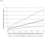
- a center-to-center distance between the center core and the outer peripheral cores is 120 ⁇ m or more.
- a fan-in/fan-out (FIFO) device can be easily achieved by bundling existing single mode fibers (with a cladding diameter of 125 ⁇ m). As a space between the centers of the center core and the outer peripheral cores is wider, a strain generated in the outer peripheral cores increases, and a wide dynamic range can be realized.
- the present invention can provide a shape measurement system and a shape measurement method that allow deriving a three-dimensional shape of a linear object to be measured over a long distance and with high resolution.
- Fig. 1 an example in which one specific core of the multi-core optical fiber 10 is connected to the measuring device 20 that measures the backward Brillouin scattering light distribution is illustrated.
- Another configuration may be in a form in which the multi-core optical fiber 10 is connected to the measuring device 20 via a fan-out mechanism that separates each core of a multi-core optical fiber into single core optical fibers and an optical switch.
- the shape measurement system includes the multi-core optical fiber 10 that is a sensing medium, the measuring device (BOTDR) 20 that detects a backward Brillouin scattering light in the propagation direction of each core of the multi-core optical fiber 10, and the analysis device 30 that analyzes measurement data obtained by the BOTDR 12.
- BOTDR measuring device
- the multi-core optical fiber 10 is installed along a longitudinal direction of a linear structural object that is a target to be measured.
- the linear structural object is, for example, a pipeline, a riser (pipe through which a fluid flows from a sea bottom to a facility above sea level in offshore drilling and marine production), a submarine cable, and the like.
- Fig. 2 is a drawing describing the cross section of the multi-core optical fiber 10.
- the multi-core optical fiber 10 has a total of four cores which are a center core located in the center of the cross section and outer peripheral cores arranged mostly at equal intervals mostly on an identical circumference from the center of the cross section.
- cores having a mostly equal refractive index distribution and optical property are used as the four cores
- cores may have a structure in which they are arranged such that the refractive index distribution and the optical property of the respective cores are purposely different.
- Restrictions of a count of cores are as follows. When the count of cores is three or less (two or less outer peripheral cores), shape identification cannot be performed. On the other hand, when the count of cores is five or more (four or more outer peripheral cores), the aspect of measurement accuracy improves, but a measurement time period increases by the count of cores.
- a circle having a certain radius can be surrounded by six circles having an identical radius that are in contact with the circle. In this case, a total count of the circles is seven. That is, a multi-core optical fiber having a core position when seven single core optical fibers having an identical diameter are arranged in a close packed manner can be formed, allowing easily making a FIFO.
- the count of outer peripheral cores in the multi-core optical fiber is preferably three or more and six or less.
- Step S03 a position in the longitudinal direction from the measuring device 20 to the multi-core optical fiber 10 is defined as z .
- Step S03 calculating a difference in strain at the position z that is a difference between a strain amount at the position z of each core of the multi-core optical fiber obtained from the backward Brillouin scattering light distribution when the multi-core optical fiber is arranged along the linear structural object having the unknown three-dimensional shape and a strain amount at the position z of each core of the multi-core optical fiber obtained from the backward Brillouin scattering light distribution when the multi-core optical fiber is arranged along the linear structural object having the already-known three-dimensional shape (Step S31), calculating a bending strain ⁇ of each of the outer peripheral cores by subtracting the difference in strain of the center core from the difference in strain of each of the outer peripheral cores (Step S32), calculating a curvature ⁇ and a bending angle ⁇ at the position z of the multi-core optical fiber from the bending strain ⁇ of each of the outer peripheral cores using the relational expression (1) (Step S33) and calculating a torsion by differentiating
- Fig. 5 is a drawing describing a specific procedure when a linear structural object having an unknown three-dimensional shape is measured by the shape measurement method.
- the multi-core optical fiber 10 is laid along a linear structural object having an already-known three-dimensional shape (for example, a water service pipe or the like that is already laid), and a distribution property of a backward Brillouin scattering light of each core in a steady state (reference state) is acquired. This is defined as reference data.
- a distribution property of the backward Brillouin scattering light of each core is acquired again in a state where the three-dimensional shape of the linear structural object is changed (for example, a water service pipe or the like that is assumed to be deformed due to an earthquake or the like). This is defined as comparison data.
- the difference in strain of the center core is subtracted from the difference in strain of each of the outer peripheral cores to derive the bending strain ⁇ at the position z for each of the outer peripheral cores.
- ⁇ r ⁇ ⁇ ⁇ cos ⁇ ⁇ ⁇
- r is the center-to-center distance between the center core 11 and the outer peripheral cores 12
- ⁇ is an angle representing a position of the outer peripheral cores 12 on the cross section of the multi-core optical fiber 10.
- r is 125 ⁇ m
- ⁇ is 0°, 120°, and 240° for each of the outer peripheral cores.
- a position vector (three-dimensional shape) of the multi-core optical fiber 10 is determined.
- the three-dimensional shape is preferably corrected using an already-known ending point.
- Fig. 6 is drawings describing a first example in which the three-dimensional shape of the multi-core optical fiber 10 is measured by the shape measurement method.
- the distance in the longitudinal direction of the multi-core optical fiber 10 (the position z described above) is expressed in s[m].
- the three-dimensional space in which the multi-core optical fiber 10 is arranged is expressed by an x-axis, a y-axis, and a z-axis. Note that the z-axis in here is different from the position z described above.
- the reference data of Step A in Fig. 5 was acquired in a state where the multi-core optical fiber 10 for sensing was extended in a straight line.
- a vicinity of the center of the multi-core optical fiber 10 was rotated clockwise at a constant curvature to acquire the comparison data of Step B in Fig. 5 .
- Figs. 6(a), (b), and (c) are results of the reference data of Step A, the comparison data of Step B, and the difference in strain of Step C in Fig. 5 , respectively.
- a dotted line, a dashed line, and a one dot chain line in the drawings each represent the difference of the outer peripheral cores.
- FIG. 6(d) and (e) illustrate evaluation results of the curvature ⁇ and the angle ⁇ of the multi-core optical fiber 10, respectively.
- Fig. 6(f) illustrates space coordinates of the multi-core optical fiber 10 in consideration of the position vector, and the curvature given to the vicinity of the center of the multi-core optical fiber 10 can be accurately detected.
- Fig. 7 is drawings describing a second example in which the three-dimensional shape of the multi-core optical fiber 10 is measured by the shape measurement method.
- the distance in the longitudinal direction of the multi-core optical fiber 10 (the position z described above) is also expressed in s[m].
- the three-dimensional space in which the multi-core optical fiber 10 is arranged is also expressed by the x-axis, the y-axis, and the z-axis. Note that the z-axis in here is different from the position z described above.
- the reference data of Step A in Fig. 5 was acquired in a state where the multi-core optical fiber 10 for sensing was extended in a straight line.
- the vicinity of the center of the multi-core optical fiber 10 was rotated counterclockwise at a constant curvature to acquire the comparison data of Step B in Fig. 5 .
- Figs. 7(a), (b), and (c) are results of the reference data of Step A, the comparison data of Step B, and the difference in strain of Step C in Fig. 5 , respectively.
- a dotted line, a dashed line, and a one dot chain line in the drawings each represent the difference of the outer peripheral cores.
- Fig. 7(d) and (e) illustrate evaluation results of the curvature ⁇ and the angle ⁇ of the multi-core optical fiber 10, respectively.
- Fig. 7(f) illustrates the space coordinates of the multi-core optical fiber 10 in consideration of the position vector, and a shape change in an opposite direction (counterclockwise) of Fig. 6(f) can be accurately detected.
- a twist is purposely added to the multi-core optical fiber used as the sensing medium.
- a strain by an unintended twist which is its twisting strain or below, can be eliminated by a calculation, and accuracy of the shape identification can be improved.
- a system configuration of the shape measurement system of the embodiment is different from the system configuration of the shape measurement system described in Fig. 1 in an already-known twist being provided to the multi-core optical fiber 10 and in an analysis procedure of the analysis device 30.
- Fig. 8 is drawings describing the multi-core optical fiber 10.
- Fig. 8(A) describes a bending strain measured in the multi-core optical fiber 10 in a state where a twist does not exist
- Fig. 8(B) describes a bending strain measured in the multi-core optical fiber 10 in a state where a twist exists.
- a core 0 is the center core
- a core 1 to a core 3 are the outer peripheral cores.
- the bending strains When the bending strains do not exist, the bending strains become zero for all the cores and overlap irrespective of the existence of a twist. For the center core, the bending strain becomes zero irrespective of the existence of a twist.
- the outer peripheral cores switch the positions by the twist in a section where the bending is given, and therefore, inversion of positives and negatives of the strain amounts can be confirmed.
- the twist is required for all the section arranged to the linear structural object.
- the analysis device 30 estimates an unintended twist generated when the multi-core optical fiber 10 is arranged along the linear structural object having an unknown three-dimensional shape, and removes an influence by the unintended twist.
- Step S33 described in the shape measurement method of Fig. 4 is different from the description of Embodiment 1. That is, in Step S03, calculating a difference in strain at the position z that is a difference between a strain amount at the position z of each core of the multi-core optical fiber obtained from the backward Brillouin scattering light distribution when the multi-core optical fiber is arranged along the linear structural object having an unknown three-dimensional shape and a strain amount at the position z of each core of the multi-core optical fiber obtained from the backward Brillouin scattering light distribution when the multi-core optical fiber is arranged along the linear structural object having an already-known three-dimensional shape (Step S31), calculating a bending strain ⁇ bending,i of each of the outer peripheral cores by subtracting the difference in strain of the center core from the difference in strain of each of the outer peripheral cores (Step S32), calculating a curvature ⁇ and a bending angle ⁇ at the position z of the multi-core optical fiber from
- Fig. 9 is a drawing describing a specific procedure when the linear structural object having an unknown three-dimensional shape is measured by the shape measurement method.
- the multi-core optical fiber 10 is laid along a linear structural object having an already-known three-dimensional shape (for example, a water service pipe or the like that is already laid), and a distribution property of a backward Brillouin scattering light of each core in a steady state (reference state) is acquired. This is defined as reference data.
- a distribution property of the backward Brillouin scattering light of each core is acquired again in a state where the three-dimensional shape of the linear structural object is changed (for example, a water service pipe or the like that is assumed to be deformed due to an earthquake or the like). This is defined as comparison data.
- a difference between the comparison data and the reference data is calculated for each core and for each position z to derive a difference in strain.
- the difference in strain of the center core is subtracted from the difference in strain of each of the outer peripheral cores to derive a strain ⁇ mix,i at the position z for each of the outer peripheral cores (here, i is 1 or larger).
- the twisting strain ⁇ twisting computed by Formula (7) is assigned to Formula (5) to compute a specific angle of twist ⁇ (z) at the position z .
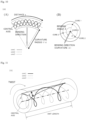
- Fig. 11 is a conceptual diagram describing a specific angle of twist ⁇ .
- r is a distance from the center on the cross section of the multi-core optical fiber 10 to the centers of the outer peripheral cores.
- k2 is a correction coefficient of a twist and expressed by the following formula.
- the bending strain ⁇ bending,i of the outer peripheral core i is computed by subtracting ⁇ twisting derived in Step D- ⁇ from the strain ⁇ mix,i of each of the outer peripheral cores.
- k 1 is a correction coefficient of a twist expressed by Formula (3).
- k 1 1 ⁇ ⁇ 2 ⁇ pr 2 2 ⁇ pr 2 + 1 where v is a Poisson's ratio of the multi-core optical fiber.
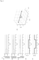
- Fig. 10 is conceptual diagrams describing a radius r, a bending direction (curvature ⁇ ), and a bending angle ⁇ of a multi-core optical fiber having three outer peripheral cores.
- Fig. 10(A) is a drawing viewed from a side surface of the multi-core optical fiber
- Fig. 10(B) is a cross-sectional view of the multi-core optical fiber.
- a position vector (three-dimensional shape) of the multi-core optical fiber 10 is determined.
- the three-dimensional shape is preferably corrected using an already-known ending point.
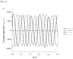
- Fig. 12 is a drawing illustrating a result of measuring in a z direction a strain of each core of a multi-core optical fiber to which a twist is applied.
- an error occurs between the number of twists (spin rate) and a design value due to a manufacturing error and the like.
- the number of twists (spin rate) is computed from a cyclic strain fluctuation by a short-time Fourier transform (STFT).
- STFT short-time Fourier transform
- the shape measurement system according to the present invention can achieve a measurement dynamic range of several kilometers to several tens of kilometers by using a backward Brillouin scattering light in shape identification of a linear structural object. Additionally, by setting the center-to-center distance between a center core and an outer peripheral core of a multi-core optical fiber used for detection of a shape change to 120 ⁇ m or more, a slight change of a curvature of 0.5[1/m] or less can be detected.
Landscapes
- Physics & Mathematics (AREA)
- General Physics & Mathematics (AREA)
- Health & Medical Sciences (AREA)
- Life Sciences & Earth Sciences (AREA)
- Chemical & Material Sciences (AREA)
- Analytical Chemistry (AREA)
- Biochemistry (AREA)
- General Health & Medical Sciences (AREA)
- Immunology (AREA)
- Pathology (AREA)
- Nonlinear Science (AREA)
- Optics & Photonics (AREA)
- Nuclear Medicine, Radiotherapy & Molecular Imaging (AREA)
- Length Measuring Devices By Optical Means (AREA)
Applications Claiming Priority (2)
| Application Number | Priority Date | Filing Date | Title |
|---|---|---|---|
| JP2020098349 | 2020-06-05 | ||
| PCT/JP2021/021283 WO2021246497A1 (ja) | 2020-06-05 | 2021-06-03 | 形状測定システム及び形状測定方法 |
Publications (3)
| Publication Number | Publication Date |
|---|---|
| EP4163586A1 EP4163586A1 (en) | 2023-04-12 |
| EP4163586A4 EP4163586A4 (en) | 2024-02-21 |
| EP4163586B1 true EP4163586B1 (en) | 2025-04-09 |
Family
ID=78831274
Family Applications (1)
| Application Number | Title | Priority Date | Filing Date |
|---|---|---|---|
| EP21818720.1A Active EP4163586B1 (en) | 2020-06-05 | 2021-06-03 | Shape measurement system and shape measurement method |
Country Status (4)
| Country | Link |
|---|---|
| US (1) | US12203847B2 (https=) |
| EP (1) | EP4163586B1 (https=) |
| JP (1) | JP7376052B2 (https=) |
| WO (1) | WO2021246497A1 (https=) |
Families Citing this family (4)
| Publication number | Priority date | Publication date | Assignee | Title |
|---|---|---|---|---|
| EP4455617A4 (en) * | 2021-12-24 | 2025-12-17 | Ntt Inc | FORM MEASURING SYSTEM AND FORM MEASURING METHOD |
| CN115900579B (zh) * | 2023-01-06 | 2023-05-26 | 山东大学 | 一种自校正可拼接式光纤位移场传感系统及其校正方法 |
| WO2025047077A1 (ja) * | 2023-08-28 | 2025-03-06 | 日本電信電話株式会社 | 測定システム、測定方法、及び、解析装置 |
| CN118149723B (zh) * | 2024-05-09 | 2024-07-19 | 武汉理工大学 | 一种长距离水下线缆姿态检测方法及系统 |
Family Cites Families (17)
| Publication number | Priority date | Publication date | Assignee | Title |
|---|---|---|---|---|
| JP4985405B2 (ja) * | 2005-09-29 | 2012-07-25 | 住友電気工業株式会社 | センサ及びそれを用いた外乱測定方法 |
| JP2007101508A (ja) * | 2005-10-07 | 2007-04-19 | Sumitomo Electric Ind Ltd | 温度測定方法及び温度測定装置 |
| US8773650B2 (en) * | 2009-09-18 | 2014-07-08 | Intuitive Surgical Operations, Inc. | Optical position and/or shape sensing |
| JP5769676B2 (ja) * | 2012-08-17 | 2015-08-26 | 公益財団法人地球環境産業技術研究機構 | 物質の圧力、温度、ひずみ分布測定システム、これを用いた二酸化炭素地中貯留の監視方法、二酸化炭素注入による地層安定性への影響評価方法、および結氷監視方法 |
| US9366526B2 (en) * | 2012-11-30 | 2016-06-14 | Neubrex Co., Ltd. | Three-dimensional position measurement system |
| US10228556B2 (en) * | 2014-04-04 | 2019-03-12 | The General Hospital Corporation | Apparatus and method for controlling propagation and/or transmission of electromagnetic radiation in flexible waveguide(s) |
| JP6346852B2 (ja) * | 2014-11-27 | 2018-06-20 | 日本電信電話株式会社 | 光ファイバの曲げ形状測定装置及びその曲げ形状測定方法 |
| US10480936B2 (en) * | 2015-06-15 | 2019-11-19 | Koninklijke Philips N.V. | Optical shape sensing system and method for sensing a position and/or shape of a medical device using backscatter reflectometry |
| CN105371781B (zh) * | 2015-11-13 | 2018-09-07 | 华中科技大学 | 一种三维形状测量方法 |
| CN108603977B (zh) * | 2016-05-11 | 2020-08-07 | 直观外科手术操作公司 | 具有用于安全性的冗余纤芯的多纤芯光学纤维 |
| US10145681B2 (en) * | 2016-07-19 | 2018-12-04 | Corning Incorporated | Brillouin-based distributed bend fiber sensor and method for using same |
| DE102016214887A1 (de) * | 2016-08-10 | 2018-02-15 | Fraunhofer-Gesellschaft zur Förderung der angewandten Forschung e.V. | Faseroptischer Sensor sowie Verfahren zu dessen Herstellung und Verwendung |
| US10530114B2 (en) * | 2017-08-31 | 2020-01-07 | United States Of America As Represented By The Administrator Of Nasa | Polarization maintaining, large mode area (PMVLMA) erbium-doped optical fiber and amplifier |
| CN110243302B (zh) * | 2018-03-08 | 2020-11-06 | 桂林电子科技大学 | 反射式多芯循环串接光纤形状传感器 |
| EP3832254B1 (en) * | 2018-07-31 | 2023-08-30 | Furukawa Electric Co., Ltd. | Cable, cable shape sensing system, sensing system, and method for sensing cable shape |
| EP3969866B1 (en) * | 2019-05-12 | 2025-12-24 | Hampidjan HF. | A process for ascertaining the elongation of a load-bearing cable |
| WO2021086129A1 (ko) * | 2019-10-31 | 2021-05-06 | (주)옵토닉스 | 3차원 곡선 형상을 측정하기 위한 특수 광섬유 및 그의 제조 방법, 그리고 특수 광섬유를 이용하여 3차원 곡선 형상을 측정하는 시스템 |
-
2021
- 2021-06-03 US US17/915,924 patent/US12203847B2/en active Active
- 2021-06-03 JP JP2022528897A patent/JP7376052B2/ja active Active
- 2021-06-03 WO PCT/JP2021/021283 patent/WO2021246497A1/ja not_active Ceased
- 2021-06-03 EP EP21818720.1A patent/EP4163586B1/en active Active
Also Published As
| Publication number | Publication date |
|---|---|
| EP4163586A1 (en) | 2023-04-12 |
| JP7376052B2 (ja) | 2023-11-08 |
| US20230147800A1 (en) | 2023-05-11 |
| JPWO2021246497A1 (https=) | 2021-12-09 |
| EP4163586A4 (en) | 2024-02-21 |
| WO2021246497A1 (ja) | 2021-12-09 |
| US12203847B2 (en) | 2025-01-21 |
Similar Documents
| Publication | Publication Date | Title |
|---|---|---|
| EP4163586B1 (en) | Shape measurement system and shape measurement method | |
| EP3832254B1 (en) | Cable, cable shape sensing system, sensing system, and method for sensing cable shape | |
| EP3521752B1 (en) | Optical position and/or shape sensing | |
| Askins et al. | Bend and twist sensing in a multiple-core optical fiber | |
| CN104154874B (zh) | 基于光纤传感的钢筋混凝土锈胀开裂的监测装置及方法 | |
| Duncan et al. | Characterization of a fiber-optic shape and position sensor | |
| CN103439766A (zh) | 一种多芯光纤的空分复用方法 | |
| US20250264374A1 (en) | Calculating distributed twist of a multi-fiber 3d shape sensor bundle (mfb) using optical frequency domain reflectometry (ofdr) phase interrogation data | |
| CN111982000A (zh) | 一种基于Beta标架的光纤形状重构方法及装置 | |
| CN110331974A (zh) | 一种基于弱光纤光栅阵列的新型油田测井光缆 | |
| EP4027126A1 (en) | Optical fiber cable sensing device, optical fiber cable sensing method, and program | |
| US11788909B2 (en) | Measuring device and measuring method using tape core wire | |
| EP4455617A1 (en) | Shape measurement system and shape measurement method | |
| Askins et al. | Bend and twist sensing in a multi-core optical fiber | |
| JP7687826B2 (ja) | ケーブル、センシングケーブル、およびセンシングシステム | |
| JP2016020865A (ja) | 光ファイバを用いた応力分布測定方法および応力分布測定装置 | |
| JP7406768B2 (ja) | 光ファイバケーブルセンシング装置、光ファイバケーブルセンシング方法、及びプログラム | |
| JP7406767B2 (ja) | 光ファイバケーブルセンシングシステム、光ファイバケーブルセンシング方法、及び光ファイバケーブル | |
| CN104634388A (zh) | 一种电力架空光缆温度及应变分布式监测装置 | |
| Nakamoto et al. | An approach to low-curvature 2D shape sensing using an indoor optical cable | |
| Bogachkov et al. | Detection of optical fiber segments with mechanical stress in optical cables using Brillouin reflectometers | |
| WO2025047077A1 (ja) | 測定システム、測定方法、及び、解析装置 | |
| RU2786937C1 (ru) | Кабельная линия | |
| li et al. | Small Curvature Shape Sensor Based on Multi-core Optical Cable with Glass Fiber Reinforced Plastic Substrate | |
| JP2023014654A (ja) | 光ファイバ曲げ方向算出システム、光ファイバ曲げ方向算出方法、光ファイバ曲げ方向算出装置及び光ファイバ曲げ方向算出プログラム |
Legal Events
| Date | Code | Title | Description |
|---|---|---|---|
| STAA | Information on the status of an ep patent application or granted ep patent |
Free format text: STATUS: THE INTERNATIONAL PUBLICATION HAS BEEN MADE |
|
| PUAI | Public reference made under article 153(3) epc to a published international application that has entered the european phase |
Free format text: ORIGINAL CODE: 0009012 |
|
| STAA | Information on the status of an ep patent application or granted ep patent |
Free format text: STATUS: REQUEST FOR EXAMINATION WAS MADE |
|
| 17P | Request for examination filed |
Effective date: 20230105 |
|
| AK | Designated contracting states |
Kind code of ref document: A1 Designated state(s): AL AT BE BG CH CY CZ DE DK EE ES FI FR GB GR HR HU IE IS IT LI LT LU LV MC MK MT NL NO PL PT RO RS SE SI SK SM TR |
|
| DAV | Request for validation of the european patent (deleted) | ||
| DAX | Request for extension of the european patent (deleted) | ||
| A4 | Supplementary search report drawn up and despatched |
Effective date: 20240123 |
|
| RIC1 | Information provided on ipc code assigned before grant |
Ipc: G01L 1/24 20060101ALI20240117BHEP Ipc: G01B 11/16 20060101AFI20240117BHEP |
|
| GRAP | Despatch of communication of intention to grant a patent |
Free format text: ORIGINAL CODE: EPIDOSNIGR1 |
|
| STAA | Information on the status of an ep patent application or granted ep patent |
Free format text: STATUS: GRANT OF PATENT IS INTENDED |
|
| INTG | Intention to grant announced |
Effective date: 20241031 |
|
| GRAS | Grant fee paid |
Free format text: ORIGINAL CODE: EPIDOSNIGR3 |
|
| GRAA | (expected) grant |
Free format text: ORIGINAL CODE: 0009210 |
|
| STAA | Information on the status of an ep patent application or granted ep patent |
Free format text: STATUS: THE PATENT HAS BEEN GRANTED |
|
| AK | Designated contracting states |
Kind code of ref document: B1 Designated state(s): AL AT BE BG CH CY CZ DE DK EE ES FI FR GB GR HR HU IE IS IT LI LT LU LV MC MK MT NL NO PL PT RO RS SE SI SK SM TR |
|
| REG | Reference to a national code |
Ref country code: GB Ref legal event code: FG4D |
|
| REG | Reference to a national code |
Ref country code: CH Ref legal event code: EP |
|
| REG | Reference to a national code |
Ref country code: DE Ref legal event code: R096 Ref document number: 602021029015 Country of ref document: DE |
|
| REG | Reference to a national code |
Ref country code: IE Ref legal event code: FG4D |
|
| PGFP | Annual fee paid to national office [announced via postgrant information from national office to epo] |
Ref country code: DE Payment date: 20250630 Year of fee payment: 5 |
|
| PGFP | Annual fee paid to national office [announced via postgrant information from national office to epo] |
Ref country code: GB Payment date: 20250611 Year of fee payment: 5 |
|
| PGFP | Annual fee paid to national office [announced via postgrant information from national office to epo] |
Ref country code: FR Payment date: 20250611 Year of fee payment: 5 |
|
| PGFP | Annual fee paid to national office [announced via postgrant information from national office to epo] |
Ref country code: AT Payment date: 20250721 Year of fee payment: 5 |
|
| REG | Reference to a national code |
Ref country code: NL Ref legal event code: MP Effective date: 20250409 |
|
| PG25 | Lapsed in a contracting state [announced via postgrant information from national office to epo] |
Ref country code: NL Free format text: LAPSE BECAUSE OF FAILURE TO SUBMIT A TRANSLATION OF THE DESCRIPTION OR TO PAY THE FEE WITHIN THE PRESCRIBED TIME-LIMIT Effective date: 20250409 |
|
| REG | Reference to a national code |
Ref country code: AT Ref legal event code: MK05 Ref document number: 1783857 Country of ref document: AT Kind code of ref document: T Effective date: 20250409 |
|
| RAP4 | Party data changed (patent owner data changed or rights of a patent transferred) |
Owner name: NTT, INC. Owner name: THE UNIVERSITY OF TOKYO |
|
| PG25 | Lapsed in a contracting state [announced via postgrant information from national office to epo] |
Ref country code: FI Free format text: LAPSE BECAUSE OF FAILURE TO SUBMIT A TRANSLATION OF THE DESCRIPTION OR TO PAY THE FEE WITHIN THE PRESCRIBED TIME-LIMIT Effective date: 20250409 Ref country code: PT Free format text: LAPSE BECAUSE OF FAILURE TO SUBMIT A TRANSLATION OF THE DESCRIPTION OR TO PAY THE FEE WITHIN THE PRESCRIBED TIME-LIMIT Effective date: 20250811 Ref country code: ES Free format text: LAPSE BECAUSE OF FAILURE TO SUBMIT A TRANSLATION OF THE DESCRIPTION OR TO PAY THE FEE WITHIN THE PRESCRIBED TIME-LIMIT Effective date: 20250409 |
|
| REG | Reference to a national code |
Ref country code: LT Ref legal event code: MG9D |
|
| PG25 | Lapsed in a contracting state [announced via postgrant information from national office to epo] |
Ref country code: NO Free format text: LAPSE BECAUSE OF FAILURE TO SUBMIT A TRANSLATION OF THE DESCRIPTION OR TO PAY THE FEE WITHIN THE PRESCRIBED TIME-LIMIT Effective date: 20250709 Ref country code: GR Free format text: LAPSE BECAUSE OF FAILURE TO SUBMIT A TRANSLATION OF THE DESCRIPTION OR TO PAY THE FEE WITHIN THE PRESCRIBED TIME-LIMIT Effective date: 20250710 |
|
| PG25 | Lapsed in a contracting state [announced via postgrant information from national office to epo] |
Ref country code: PL Free format text: LAPSE BECAUSE OF FAILURE TO SUBMIT A TRANSLATION OF THE DESCRIPTION OR TO PAY THE FEE WITHIN THE PRESCRIBED TIME-LIMIT Effective date: 20250409 |
|
| PG25 | Lapsed in a contracting state [announced via postgrant information from national office to epo] |
Ref country code: BG Free format text: LAPSE BECAUSE OF FAILURE TO SUBMIT A TRANSLATION OF THE DESCRIPTION OR TO PAY THE FEE WITHIN THE PRESCRIBED TIME-LIMIT Effective date: 20250409 |
|
| PG25 | Lapsed in a contracting state [announced via postgrant information from national office to epo] |
Ref country code: HR Free format text: LAPSE BECAUSE OF FAILURE TO SUBMIT A TRANSLATION OF THE DESCRIPTION OR TO PAY THE FEE WITHIN THE PRESCRIBED TIME-LIMIT Effective date: 20250409 |
|
| PG25 | Lapsed in a contracting state [announced via postgrant information from national office to epo] |
Ref country code: AT Free format text: LAPSE BECAUSE OF FAILURE TO SUBMIT A TRANSLATION OF THE DESCRIPTION OR TO PAY THE FEE WITHIN THE PRESCRIBED TIME-LIMIT Effective date: 20250409 |
|
| PG25 | Lapsed in a contracting state [announced via postgrant information from national office to epo] |
Ref country code: RS Free format text: LAPSE BECAUSE OF FAILURE TO SUBMIT A TRANSLATION OF THE DESCRIPTION OR TO PAY THE FEE WITHIN THE PRESCRIBED TIME-LIMIT Effective date: 20250709 |
|
| PG25 | Lapsed in a contracting state [announced via postgrant information from national office to epo] |
Ref country code: IS Free format text: LAPSE BECAUSE OF FAILURE TO SUBMIT A TRANSLATION OF THE DESCRIPTION OR TO PAY THE FEE WITHIN THE PRESCRIBED TIME-LIMIT Effective date: 20250809 |
|
| PG25 | Lapsed in a contracting state [announced via postgrant information from national office to epo] |
Ref country code: LV Free format text: LAPSE BECAUSE OF FAILURE TO SUBMIT A TRANSLATION OF THE DESCRIPTION OR TO PAY THE FEE WITHIN THE PRESCRIBED TIME-LIMIT Effective date: 20250409 |
|
| REG | Reference to a national code |
Ref country code: DE Ref legal event code: R097 Ref document number: 602021029015 Country of ref document: DE |
|
| PG25 | Lapsed in a contracting state [announced via postgrant information from national office to epo] |
Ref country code: DK Free format text: LAPSE BECAUSE OF FAILURE TO SUBMIT A TRANSLATION OF THE DESCRIPTION OR TO PAY THE FEE WITHIN THE PRESCRIBED TIME-LIMIT Effective date: 20250409 Ref country code: SM Free format text: LAPSE BECAUSE OF FAILURE TO SUBMIT A TRANSLATION OF THE DESCRIPTION OR TO PAY THE FEE WITHIN THE PRESCRIBED TIME-LIMIT Effective date: 20250409 |
|
| PG25 | Lapsed in a contracting state [announced via postgrant information from national office to epo] |
Ref country code: CZ Free format text: LAPSE BECAUSE OF FAILURE TO SUBMIT A TRANSLATION OF THE DESCRIPTION OR TO PAY THE FEE WITHIN THE PRESCRIBED TIME-LIMIT Effective date: 20250409 |
|
| PG25 | Lapsed in a contracting state [announced via postgrant information from national office to epo] |
Ref country code: EE Free format text: LAPSE BECAUSE OF FAILURE TO SUBMIT A TRANSLATION OF THE DESCRIPTION OR TO PAY THE FEE WITHIN THE PRESCRIBED TIME-LIMIT Effective date: 20250409 |
|
| PG25 | Lapsed in a contracting state [announced via postgrant information from national office to epo] |
Ref country code: SK Free format text: LAPSE BECAUSE OF FAILURE TO SUBMIT A TRANSLATION OF THE DESCRIPTION OR TO PAY THE FEE WITHIN THE PRESCRIBED TIME-LIMIT Effective date: 20250409 |
|
| REG | Reference to a national code |
Ref country code: CH Ref legal event code: H13 Free format text: ST27 STATUS EVENT CODE: U-0-0-H10-H13 (AS PROVIDED BY THE NATIONAL OFFICE) Effective date: 20260127 |
|
| PG25 | Lapsed in a contracting state [announced via postgrant information from national office to epo] |
Ref country code: IT Free format text: LAPSE BECAUSE OF FAILURE TO SUBMIT A TRANSLATION OF THE DESCRIPTION OR TO PAY THE FEE WITHIN THE PRESCRIBED TIME-LIMIT Effective date: 20250409 |
|
| PG25 | Lapsed in a contracting state [announced via postgrant information from national office to epo] |
Ref country code: MC Free format text: LAPSE BECAUSE OF FAILURE TO SUBMIT A TRANSLATION OF THE DESCRIPTION OR TO PAY THE FEE WITHIN THE PRESCRIBED TIME-LIMIT Effective date: 20250409 |
|
| PG25 | Lapsed in a contracting state [announced via postgrant information from national office to epo] |
Ref country code: RO Free format text: LAPSE BECAUSE OF FAILURE TO SUBMIT A TRANSLATION OF THE DESCRIPTION OR TO PAY THE FEE WITHIN THE PRESCRIBED TIME-LIMIT Effective date: 20250409 |
|
| PLBE | No opposition filed within time limit |
Free format text: ORIGINAL CODE: 0009261 |
|
| STAA | Information on the status of an ep patent application or granted ep patent |
Free format text: STATUS: NO OPPOSITION FILED WITHIN TIME LIMIT |
|
| PG25 | Lapsed in a contracting state [announced via postgrant information from national office to epo] |
Ref country code: LU Free format text: LAPSE BECAUSE OF NON-PAYMENT OF DUE FEES Effective date: 20250603 |
|
| REG | Reference to a national code |
Ref country code: CH Ref legal event code: L10 Free format text: ST27 STATUS EVENT CODE: U-0-0-L10-L00 (AS PROVIDED BY THE NATIONAL OFFICE) Effective date: 20260218 |
|
| REG | Reference to a national code |
Ref country code: BE Ref legal event code: MM Effective date: 20250630 |
|
| REG | Reference to a national code |
Ref country code: DE Ref legal event code: R081 Ref document number: 602021029015 Country of ref document: DE Owner name: NTT, INC., JP Free format text: FORMER OWNERS: NIPPON TELEGRAPH AND TELEPHONE CORPORATION, TOKYO, JP; THE UNIVERSITY OF TOKYO, TOKYO, JP Ref country code: DE Ref legal event code: R081 Ref document number: 602021029015 Country of ref document: DE Owner name: THE UNIVERSITY OF TOKYO, JP Free format text: FORMER OWNERS: NIPPON TELEGRAPH AND TELEPHONE CORPORATION, TOKYO, JP; THE UNIVERSITY OF TOKYO, TOKYO, JP Ref country code: DE Ref legal event code: R082 Ref document number: 602021029015 Country of ref document: DE Representative=s name: DENNEMEYER & ASSOCIATES RECHTSANWALTSGESELLSCH, DE |
|
| 26N | No opposition filed |
Effective date: 20260112 |
|
| PG25 | Lapsed in a contracting state [announced via postgrant information from national office to epo] |
Ref country code: IE Free format text: LAPSE BECAUSE OF NON-PAYMENT OF DUE FEES Effective date: 20250603 |
|
| PG25 | Lapsed in a contracting state [announced via postgrant information from national office to epo] |
Ref country code: BE Free format text: LAPSE BECAUSE OF NON-PAYMENT OF DUE FEES Effective date: 20250630 |