EP4163572A1 - Refrigerant distributor, heat exchanger, and air-conditioning device - Google Patents
Refrigerant distributor, heat exchanger, and air-conditioning device Download PDFInfo
- Publication number
- EP4163572A1 EP4163572A1 EP20938873.5A EP20938873A EP4163572A1 EP 4163572 A1 EP4163572 A1 EP 4163572A1 EP 20938873 A EP20938873 A EP 20938873A EP 4163572 A1 EP4163572 A1 EP 4163572A1
- Authority
- EP
- European Patent Office
- Prior art keywords
- refrigerant
- plate
- passages
- passage
- distributer
- Prior art date
- Legal status (The legal status is an assumption and is not a legal conclusion. Google has not performed a legal analysis and makes no representation as to the accuracy of the status listed.)
- Withdrawn
Links
Images






Classifications
-
- F—MECHANICAL ENGINEERING; LIGHTING; HEATING; WEAPONS; BLASTING
- F28—HEAT EXCHANGE IN GENERAL
- F28F—DETAILS OF HEAT-EXCHANGE AND HEAT-TRANSFER APPARATUS, OF GENERAL APPLICATION
- F28F9/00—Casings; Header boxes; Auxiliary supports for elements; Auxiliary members within casings
- F28F9/02—Header boxes; End plates
- F28F9/0202—Header boxes having their inner space divided by partitions
-
- F—MECHANICAL ENGINEERING; LIGHTING; HEATING; WEAPONS; BLASTING
- F25—REFRIGERATION OR COOLING; COMBINED HEATING AND REFRIGERATION SYSTEMS; HEAT PUMP SYSTEMS; MANUFACTURE OR STORAGE OF ICE; LIQUEFACTION SOLIDIFICATION OF GASES
- F25B—REFRIGERATION MACHINES, PLANTS OR SYSTEMS; COMBINED HEATING AND REFRIGERATION SYSTEMS; HEAT PUMP SYSTEMS
- F25B39/00—Evaporators; Condensers
- F25B39/02—Evaporators
- F25B39/028—Evaporators having distributing means
-
- F—MECHANICAL ENGINEERING; LIGHTING; HEATING; WEAPONS; BLASTING
- F25—REFRIGERATION OR COOLING; COMBINED HEATING AND REFRIGERATION SYSTEMS; HEAT PUMP SYSTEMS; MANUFACTURE OR STORAGE OF ICE; LIQUEFACTION SOLIDIFICATION OF GASES
- F25B—REFRIGERATION MACHINES, PLANTS OR SYSTEMS; COMBINED HEATING AND REFRIGERATION SYSTEMS; HEAT PUMP SYSTEMS
- F25B39/00—Evaporators; Condensers
- F25B39/04—Condensers
-
- F—MECHANICAL ENGINEERING; LIGHTING; HEATING; WEAPONS; BLASTING
- F28—HEAT EXCHANGE IN GENERAL
- F28D—HEAT-EXCHANGE APPARATUS, NOT PROVIDED FOR IN ANOTHER SUBCLASS, IN WHICH THE HEAT-EXCHANGE MEDIA DO NOT COME INTO DIRECT CONTACT
- F28D1/00—Heat-exchange apparatus having stationary conduit assemblies for one heat-exchange medium only, the media being in contact with different sides of the conduit wall, in which the other heat-exchange medium is a large body of fluid, e.g. domestic or motor car radiators
- F28D1/02—Heat-exchange apparatus having stationary conduit assemblies for one heat-exchange medium only, the media being in contact with different sides of the conduit wall, in which the other heat-exchange medium is a large body of fluid, e.g. domestic or motor car radiators with heat-exchange conduits immersed in the body of fluid
- F28D1/04—Heat-exchange apparatus having stationary conduit assemblies for one heat-exchange medium only, the media being in contact with different sides of the conduit wall, in which the other heat-exchange medium is a large body of fluid, e.g. domestic or motor car radiators with heat-exchange conduits immersed in the body of fluid with tubular conduits
- F28D1/053—Heat-exchange apparatus having stationary conduit assemblies for one heat-exchange medium only, the media being in contact with different sides of the conduit wall, in which the other heat-exchange medium is a large body of fluid, e.g. domestic or motor car radiators with heat-exchange conduits immersed in the body of fluid with tubular conduits the conduits being straight
- F28D1/0535—Heat-exchange apparatus having stationary conduit assemblies for one heat-exchange medium only, the media being in contact with different sides of the conduit wall, in which the other heat-exchange medium is a large body of fluid, e.g. domestic or motor car radiators with heat-exchange conduits immersed in the body of fluid with tubular conduits the conduits being straight the conduits having a non-circular cross-section
- F28D1/05366—Assemblies of conduits connected to common headers, e.g. core type radiators
- F28D1/05391—Assemblies of conduits connected to common headers, e.g. core type radiators with multiple rows of conduits or with multi-channel conduits combined with a particular flow pattern, e.g. multi-row multi-stage radiators
-
- F—MECHANICAL ENGINEERING; LIGHTING; HEATING; WEAPONS; BLASTING
- F28—HEAT EXCHANGE IN GENERAL
- F28D—HEAT-EXCHANGE APPARATUS, NOT PROVIDED FOR IN ANOTHER SUBCLASS, IN WHICH THE HEAT-EXCHANGE MEDIA DO NOT COME INTO DIRECT CONTACT
- F28D7/00—Heat-exchange apparatus having stationary tubular conduit assemblies for both heat-exchange media, the media being in contact with different sides of a conduit wall
- F28D7/16—Heat-exchange apparatus having stationary tubular conduit assemblies for both heat-exchange media, the media being in contact with different sides of a conduit wall the conduits being arranged in parallel spaced relation
-
- F—MECHANICAL ENGINEERING; LIGHTING; HEATING; WEAPONS; BLASTING
- F28—HEAT EXCHANGE IN GENERAL
- F28F—DETAILS OF HEAT-EXCHANGE AND HEAT-TRANSFER APPARATUS, OF GENERAL APPLICATION
- F28F9/00—Casings; Header boxes; Auxiliary supports for elements; Auxiliary members within casings
- F28F9/02—Header boxes; End plates
- F28F9/0246—Arrangements for connecting header boxes with flow lines
-
- F—MECHANICAL ENGINEERING; LIGHTING; HEATING; WEAPONS; BLASTING
- F28—HEAT EXCHANGE IN GENERAL
- F28F—DETAILS OF HEAT-EXCHANGE AND HEAT-TRANSFER APPARATUS, OF GENERAL APPLICATION
- F28F9/00—Casings; Header boxes; Auxiliary supports for elements; Auxiliary members within casings
- F28F9/02—Header boxes; End plates
- F28F9/026—Header boxes; End plates with static flow control means, e.g. with means for uniformly distributing heat exchange media into conduits
- F28F9/0278—Header boxes; End plates with static flow control means, e.g. with means for uniformly distributing heat exchange media into conduits in the form of stacked distribution plates or perforated plates arranged over end plates
-
- F—MECHANICAL ENGINEERING; LIGHTING; HEATING; WEAPONS; BLASTING
- F25—REFRIGERATION OR COOLING; COMBINED HEATING AND REFRIGERATION SYSTEMS; HEAT PUMP SYSTEMS; MANUFACTURE OR STORAGE OF ICE; LIQUEFACTION SOLIDIFICATION OF GASES
- F25B—REFRIGERATION MACHINES, PLANTS OR SYSTEMS; COMBINED HEATING AND REFRIGERATION SYSTEMS; HEAT PUMP SYSTEMS
- F25B13/00—Compression machines, plants or systems, with reversible cycle
-
- F—MECHANICAL ENGINEERING; LIGHTING; HEATING; WEAPONS; BLASTING
- F28—HEAT EXCHANGE IN GENERAL
- F28D—HEAT-EXCHANGE APPARATUS, NOT PROVIDED FOR IN ANOTHER SUBCLASS, IN WHICH THE HEAT-EXCHANGE MEDIA DO NOT COME INTO DIRECT CONTACT
- F28D21/00—Heat-exchange apparatus not covered by any of the groups F28D1/00 - F28D20/00
- F28D2021/0019—Other heat exchangers for particular applications; Heat exchange systems not otherwise provided for
- F28D2021/0068—Other heat exchangers for particular applications; Heat exchange systems not otherwise provided for for refrigerant cycles
Definitions
- the present disclosure relates to a refrigerant distributer, a heat exchanger, and an air-conditioning apparatus.
- the refrigerant distributer is configured to divert, into a plurality of refrigerant flows, refrigerant flowing in and allow the refrigerant flows to be let out.
- heat exchangers usable in an air-conditioning apparatus to include heat transfer tubes having a smaller diameter.
- the diameter of heat transfer tubes is reduced, it is necessary to inhibit an increase in pressure loss of refrigerant that passes through the heat transfer tubes.
- the number of paths in a heat exchanger is increased.
- heat exchangers usually include a multi-branch refrigerant distributer configured to distribute and supply, to a plurality of paths, refrigerant flowing in from one inlet passage.
- a refrigerant distributer that is disposed to extend in a vertical direction and that is formed in a header connected to a plurality of heat transfer tubes disposed side by side in the vertical direction, the heat transfer tubes extending in a horizontal direction.
- this refrigerant distributer When a heat exchanger functions as an evaporator, this refrigerant distributer includes an inlet pipe into which two-phase gas-liquid refrigerant flows, a mixing chamber in which gas refrigerant and liquid refrigerant forming two-phase gas-liquid refrigerant flowing in are mixed to form homogenized refrigerant, communication chambers connected to the heat transfer tubes, and distribution passages through which two-phase gas-liquid refrigerant is distributed to the communication chambers.
- Patent Literature 1 Japanese Patent No. 5376010
- the refrigerant distributer described in Patent Literature 1 has a large size, thus resulting in a reduction in the mounting area of the heat exchanger. Accordingly, this refrigerant distributer has a problem of impairing heat exchanger performance.
- the present disclosure is made in view of the problem in the related art, and an object of the present disclosure is to provide a refrigerant distributer, a heat exchanger, and an air-conditioning apparatus, the refrigerant distributer inhibiting an increase in the size and thus inhibiting a reduction in the mounting area of a heat exchanger to enable an improvement in heat exchanger performance.
- a refrigerant distributer in an embodiment of the present disclosure includes a plurality of plates.
- the refrigerant distributer is configured to divert, into a plurality of refrigerant flows, refrigerant flowing in from one or a plurality of inlet ports thereof and allow the refrigerant flows to be let out from a plurality of outlet ports thereof spaced from one another in a first direction.
- the plurality of plates include: an inflow plate having one of the plurality of inlet ports; a communication plate having a communication chamber communicating with the one of the plurality of inlet ports of the inflow plate; and a heat transfer tube insertion plate into which a heat transfer tube communicating with one of the plurality of outlet ports is inserted, the heat transfer tube insertion plate having heat transfer tube insertion space through which a plurality of the heat transfer tubes communicate with the communication chamber.
- a heat exchanger in another embodiment of the present disclosure includes: the refrigerant distributer according to the embodiment of the present disclosure; and a plurality of heat transfer tubes connected to the plurality of respective outlet ports.
- An air-conditioning apparatus in still another embodiment of the present disclosure includes the heat exchanger according to the other embodiment of the present disclosure.
- formation of the communication chamber communicating with the heat transfer tubes enables a reduction in the thickness of the refrigerant distributer, thus inhibiting an increase in the size of the refrigerant distributer and thus inhibiting a reduction in the mounting area of the heat exchanger to enable an improvement in heat exchanger performance.
- a refrigerant distributer according to Embodiment 1 will be described below with reference to the drawings, for example.
- the refrigerant distributer according to Embodiment 1 configured to distribute refrigerant to flow into a heat exchanger will be described below, but the configuration is not limited thereto.
- the refrigerant distributer may be configured to distribute refrigerant to flow into a different device.
- components having the same reference signs are the same or corresponding components, and this applies to the entire embodiments described below.
- the size relationships of the components in the drawings may differ from those of actual ones.
- illustration of detailed structures is simplified or omitted as appropriate.
- the forms of the components in the entire description are merely examples, and the forms of the components are not limited to those in the description.
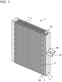
- Fig. 1 is a perspective view illustrating an example of the configuration of a heat exchanger according to Embodiment 1.
- the heat exchanger 1 includes a refrigerant distributer 2, a gas header 3, a plurality of heat transfer tubes 4, and a plurality of fins 5.
- the refrigerant distributer 2 has one or a plurality of refrigerant inlet portions 2A, which are inlet ports for refrigerant, and a plurality of refrigerant outlet portions 2B, which are outlet ports for refrigerant.
- the refrigerant outlet portions 2B are arranged in the height direction.
- the gas header 3 has a plurality of refrigerant inlet portions 3A and one refrigerant outlet portion 3B.
- Refrigerant pipes of a refrigeration cycle apparatus such as an air-conditioning apparatus are connected to the one or the plurality of refrigerant inlet portions 2A of the refrigerant distributer 2 and the refrigerant outlet portion 3B of the gas header 3.
- the heat transfer tubes 4 are connected between the refrigerant outlet portions 2B of the refrigerant distributer 2 and the refrigerant inlet portions 3A of the gas header 3.
- Each of the heat transfer tubes 4 is a flat tube or a circular tube having a plurality of passages.
- the heat transfer tube 4 is made of, for example, copper or aluminum.
- An end portion of each of the heat transfer tubes 4 closer to the refrigerant distributer 2 is connected to a corresponding one of the refrigerant outlet portions 2B of the refrigerant distributer 2.
- the fins 5 are joined to the heat transfer tubes 4.
- Each of the fins 5 is made of, for example, aluminum.
- Fig. 1 illustrates an example in which the number of the heat transfer tubes 4 is eight. However, the number of the heat transfer tubes 4 is not limited thereto and may be any number as long as the number is two or more.
- the refrigerant flow in the heat exchanger 1 according to Embodiment 1 will be described.
- refrigerant flowing in refrigerant pipes flows into the refrigerant distributer 2 via the one or the plurality of refrigerant inlet portions 2A and is distributed to and flows out into the heat transfer tubes 4 via the refrigerant outlet portions 2B.
- the distributed refrigerants in the heat transfer tubes 4 are subjected to heat exchange with, for example, air supplied by a fan (not illustrated).
- the refrigerants flowing in the heat transfer tubes 4 flow into the gas header 3 via the refrigerant inlet portions 3A and join together.
- the joined refrigerant flows out into a refrigerant pipe via the refrigerant outlet portion 3B.
- refrigerant flows in the direction opposite to this flow direction.
- Fig. 2 is an exploded perspective view illustrating an example of the configuration of a refrigerant distributer according to Embodiment 1.
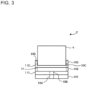
- Fig. 3 is a schematic diagram for describing the relationship between passages when the refrigerant distributer in Fig. 2 is viewed from above. To make the relationship between the passages formed in plates easy to understand, Fig. 3 illustrates the passages with dashed lines.
- Fig. 4 is a schematic diagram illustrating an example of the positional relationship between the passages when the refrigerant distributer in Fig. 2 is viewed from the front.
- the refrigerant distributer 2 is formed by stacking a plurality of plates 10, which have, for example, a rectangular shape.
- the plates 10 are formed by alternately stacking first plates 101, 102, and 103 and second plates 111 and 112.
- the first plates 101, 102, and 103 and the second plates 111 and 112 have the same outside shape in plan view.
- the second plates 111 and 112 are partition plates for partitioning off the first plates 101, 102, and 103.
- a soldering material is applied to both surfaces of each of the second plates 111 and 112.
- the first plates 101, 102, and 103 are stacked via the second plates 111 and 112 and are joined together by soldering.
- the plates are each made by, for example, press work or cutting work.
- the first plate 101 has one or a plurality of first passages 10A, which are through holes and which are located at substantially the center of the first plate 101 in the short-side direction.
- a capillary tube or a refrigerant pipe of a refrigeration cycle apparatus is connected to the first passage 10A.
- the first passage 10A corresponds to the refrigerant inlet portion 2A in Fig. 1 .
- the first plate 101 is an inflow plate having the one or the plurality of first passages 10A, which are the refrigerant inlet portions 2A serving as inlet ports.
- Fig. 2 illustrates an example in which capillary tubes are connected to the first plate 101.
- the first plate 101 has the plurality of first passages 10A.
- the first plate 101 can have the one first passage 10A.
- the second plate 111 has one or a plurality of second passages 10B, which are through holes and which are located at substantially the center of the second plate 111 in the short-side direction.
- the second passage 10B is formed at a position depending on the position of the corresponding first passage 10A of the first plate 101 and allows the first passage 10A and the corresponding communication chamber 11 of the first plate 102, which will be described later, to communicate with one another.
- the first plate 102 has a plurality of communication chambers 11.
- the communication chamber 11 is formed to depend on the position of the corresponding second passage 10B of the second plate 111 and allows the second passage 10B and the corresponding third passage 10C of the second plate 112, which will be described later, to communicate with one another.
- the communication chambers 11 are formed to communicate with a plurality of third passages 10C. In this example, each of the communication chambers 11 is formed to communicate with corresponding two of the third passages 10C.
- the first plate 102 is a communication plate having the communication chambers 11, which serve as communication passages communicating with the refrigerant inlet portions 2A serving as inlet ports.
- the second plate 112 has the third passages 10C, each of which has the same shape as the outside shape of the heat transfer tube 4.
- the third passage 10C holds the end portion of the heat transfer tube 4 inserted thereinto via the corresponding fourth passage 10D of the first plate 103, which will be described later.
- the first plate 103 has a plurality of fourth passages 10D, each of which is heat transfer tube insertion space having the same shape as the outside shape of the heat transfer tube 4.
- the fourth passage 10D is formed to depend on the position of the corresponding third passage 10C of the second plate 112.
- the heat transfer tube 4 is inserted into the fourth passage 10D.
- the heat transfer tubes 4 are soldered to the first plate 103, and the first plate 103 and the second plate 112 are stacked. Thus, the heat transfer tubes 4 are connected to the respective third passages 10C of the second plate 112.
- the first plate 103 is a heat transfer tube insertion plate having the fourth passages 10D, each of which is the heat transfer tube insertion space into which the heat transfer tube 4 is inserted.
- the refrigerant distributer 2 has distribution passages 2a, which are formed by the passages of each of the first plates 101, 102, and 103 and the second plates 111 and 112. That is, the distribution passages 2a are formed by the first passages 10A, the second passages 10B, the third passages 10C, the fourth passages 10D, and the communication chambers 11.
- the refrigerant flow and the distribution passages 2a in the refrigerant distributer 2 will be described with reference to Figs. 2 to 4 .
- the heat exchanger 1 functions as an evaporator
- two-phase gas-liquid refrigerant flows into the refrigerant distributer 2 from the first passages 10A of the first plate 101.
- the refrigerant that has flowed into the refrigerant distributer 2 flows into each of the communication chambers 11 of the first plate 102 via the corresponding second passage 10B of the second plate 111.
- the refrigerant that has flowed into the communication chamber 11 flows into the third passages 10C of the second plate 112 that communicate with the communication chamber 11 and is diverted.
- the diverted refrigerant flows enter the respective fourth passages 10D of the second plate 112, each of which is the heat transfer tube insertion space, and are equally distributed to the heat transfer tubes 4 connected to the respective fourth passages 10D.
- the heat exchanger 1 is used in an air-conditioning apparatus 80
- the configuration is not limited thereto.
- the heat exchanger 1 may be used in a different refrigeration cycle apparatus including a refrigerant cycle circuit.
- the air-conditioning apparatus 80 is configured to switch between a cooling operation and a heating operation
- the air-conditioning apparatus 80 may be configured to perform only one of the cooling operation and the heating operation.
- Fig. 5 is a schematic diagram illustrating an example of the configuration of the air-conditioning apparatus 80 to which the heat exchanger 1 according to Embodiment 1 is applied.
- a refrigerant flow in the cooling operation is represented by dashed arrows
- a refrigerant flow in the heating operation is represented by solid arrows.
- the air-conditioning apparatus 80 includes a compressor 81, a four-way valve 82, an outdoor heat exchanger 83, an expansion valve 84, an indoor heat exchanger 85, an outdoor fan 86, and an indoor fan 87.
- a refrigerant cycle circuit is formed by connecting, by refrigerant pipes, the compressor 81, the four-way valve 82, the outdoor heat exchanger 83, the expansion valve 84, and the indoor heat exchanger 85.
- High-pressure, high-temperature gas refrigerant discharged from the compressor 81 flows into the outdoor heat exchanger 83 via the four-way valve 82 and is condensed into high-pressure liquid refrigerant by being subjected to heat exchange with air supplied by the outdoor fan 86.
- the high-pressure liquid refrigerant flows out from the outdoor heat exchanger 83 and becomes low-pressure two-phase gas-liquid refrigerant by passing through the expansion valve 84.
- the low-pressure two-phase gas-liquid refrigerant flows into the indoor heat exchanger 85 and is evaporated, to cool an indoor space, into low-pressure gas refrigerant by being subjected to heat exchange with air supplied by the indoor fan 87.
- the low-pressure gas refrigerant flows out from the indoor heat exchanger 85 and is suctioned into the compressor 81 via the four-way valve 82.
- High-pressure, high-temperature gas refrigerant discharged from the compressor 81 flows into the indoor heat exchanger 85 via the four-way valve 82 and is condensed, to heat an indoor space, into high-pressure liquid refrigerant by being subjected to heat exchange with air supplied by the indoor fan 87.
- the high-pressure liquid refrigerant flows out from the indoor heat exchanger 85 and becomes low-pressure two-phase gas-liquid refrigerant by passing through the expansion valve 84.
- the low-pressure two-phase gas-liquid refrigerant flows into the outdoor heat exchanger 83 and is evaporated into low-pressure gas refrigerant by being subjected to heat exchange with air supplied by the outdoor fan 86.
- the low-pressure gas refrigerant flows out from the outdoor heat exchanger 83 and is suctioned into the compressor 81 via the four-way valve 82.
- the heat exchanger 1 is used as at least one of the outdoor heat exchanger 83 and the indoor heat exchanger 85.
- the heat exchanger 1 functions as an evaporator
- the heat exchanger 1 is connected such that refrigerant flows in from the refrigerant distributer 2. That is, when the heat exchanger 1 functions as an evaporator, two-phase gas-liquid refrigerant flows into the refrigerant distributer 2 from a refrigerant pipe and is diverted to flow into each of the heat transfer tubes 4 of the heat exchanger 1.
- the heat exchanger 1 functions as a condenser
- liquid refrigerants flow into the refrigerant distributer 2 from the respective heat transfer tubes 4 and join together to flow out into a refrigerant pipe.
- the refrigerant distributer 2 includes the first plate 101, which has the first passages 10A, the first plate 102, which has the communication chambers 11 communicating with the respective first passages 10A, and the first plate 103, which has the third passages 10C, through which a plurality of the heat transfer tubes 4 communicate with each of the communication chambers 11.
- formation of the communication chamber 11 communicating with the heat transfer tubes 4 enables a reduction in the thickness of the refrigerant distributer 2 compared with a case in which the refrigerant distributer has a cylindrical shape. Accordingly, it is possible to reduce the size of the refrigerant distributer 2.
- a reduction in the size of the refrigerant distributer 2 in an air-conditioning apparatus including a casing having a consistent size results in an increase in the mounting area of the heat exchanger 1. Thus, it is possible to improve the heat exchanger performance.
- Embodiment 2 will be described.
- the refrigerant distributer 2 according to Embodiment 2 differs from that in Embodiment 1 in the positions where the first passages 10A of the first plate 101 are disposed and the positions where the second passages 10B of the second plate 111 are disposed.
- parts common to Embodiment 1 and Embodiment 2 have the same reference signs, and detailed descriptions thereof are omitted.
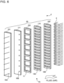
- Fig. 6 is an exploded perspective view illustrating an example of the configuration of a refrigerant distributer according to Embodiment 2.
- Fig. 7 is a schematic diagram for describing the relationship between passages when the refrigerant distributer in Fig. 6 is viewed from above. To make the relationship between the passages formed in the plates easy to understand, Fig. 7 illustrates the passages with dashed lines.
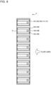
- Fig. 8 is a schematic diagram illustrating an example of the positional relationship between the passages when the refrigerant distributer in Fig. 6 is viewed from the front.
- the refrigerant distributer 2 is formed by stacking a plurality of plates 20, which have, for example, a rectangular shape.
- the plates 20 are formed by alternately stacking the first plates 101, 102, and 103 and the second plates 111 and 112.
- the first plates 102 and 103 and the second plate 112 are similar to those in Embodiment 1.
- the refrigerant distributer 2 has the distribution passages 2a, which are formed by the passages of each of the first plates 101, 102, and 103 and the second plates 111 and 112. That is, similarly to Embodiment 1, the distribution passages 2a are formed by the first passages 10A, the second passages 10B, the third passages 10C, the fourth passages 10D, and the communication chambers 11.
- the first plate 101 has the one or the plurality of first passages 10A, to which capillary tubes or a refrigerant pipe of a refrigeration cycle apparatus is connected.
- Fig. 6 illustrates an example in which capillary tubes are connected to the first plate 101.
- the second plate 111 has the one or the plurality of second passages 10B, each of which is located at a position depending on the position of the corresponding first passage 10A of the first plate 101.
- the first passages 10A of the first plate 101 and the second passages 10B of the second plate 111 are disposed such that a larger amount of refrigerant flows in the part located upstream of the fluid flow having a high heat transfer performance.
- the first passages 10A and the second passages 10B are unevenly provided to be upstream of the fluid flow relative to the central position of the plates 10 in the short-side direction.
- the heat exchanger 1 including this refrigerant distributer 2 functions as an evaporator into which two-phase gas-liquid refrigerant flows, a large amount of two-phase gas-liquid refrigerant flows in the part located upstream of the fluid flow in which the amount of heat exchange is larger than that in the part located downstream of the fluid flow, thus improving the heat transfer performance of the part of the heat exchanger 1 located upstream of the fluid flow. Accordingly, it is possible to improve the heat exchanger performance.
- the first passages 10A are formed in the first plate 101 such that the first passages 10A are located upstream of the fluid flow outside the heat transfer tubes 4.
- a larger amount of refrigerant flows in the part located upstream of the fluid, thus improving the heat transfer performance of the part located upstream thereof in which the amount of heat exchange is large. Accordingly, it is possible to improve the heat exchanger performance.
- Embodiment 3 will be described.
- the refrigerant distributer 2 according to Embodiment 3 differs from that in each of Embodiments 1 and 2 in the shape of the communication chamber 11 of the first plate 102.
- parts common to Embodiment 3 and Embodiment 1 or 2 have the same reference signs, and detailed descriptions thereof are omitted.
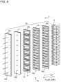
- Fig. 9 is an exploded perspective view illustrating an example of the configuration of a refrigerant distributer according to Embodiment 3.
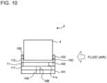
- Fig. 10 is a schematic diagram for describing the relationship between passages when the refrigerant distributer in Fig. 9 is viewed from above. To make the relationship between the passages formed in the plates easy to understand, Fig. 10 illustrates the passages with dashed lines.
- Fig. 11 is a schematic diagram illustrating an example of the positional relationship between the passages when the refrigerant distributer in Fig. 9 is viewed from the front.
- the refrigerant distributer 2 is formed by stacking a plurality of plates 30, which have, for example, a rectangular shape.
- the plates 30 are formed by alternately stacking the first plates 101, 102, and 103 and the second plates 111 and 112.
- the first plates 101 and 103 and the second plates 111 and 112 are similar to those in Embodiment 1.
- the refrigerant distributer 2 has the distribution passages 2a, which are formed by the passages of each of the first plates 101, 102, and 103 and the second plates 111 and 112. That is, similarly to Embodiments 1 and 2, the distribution passages 2a are formed by the first passages 10A, the second passages 10B, the third passages 10C, the fourth passages 10D, and the communication chambers 11.
- the first plate 102 has the plurality of communication chambers 11, each of which is formed to depend on the position of the corresponding second passage 10B of the second plate 111.
- the communication chamber 11 has a descent inhibiting portion 11a.
- the descent inhibiting portion 11a is provided such that the descent inhibiting portion 11a is unevenly located to be downstream of a fluid flow. As illustrated in Fig. 11 , the descent inhibiting portion 11a is provided to be located lower than the position of the corresponding second passage 10B.
- a passage flow resistance applied downward in the direction of gravity against refrigerant flowing in is usually large. Provision of the descent inhibiting portion 11a lower than the position where refrigerant flows in causes the flow resistance in a lower part of the communication chamber 11 to be larger than that in an upper part of the communication chamber 11. Accordingly, liquid refrigerant forming two-phase gas-liquid refrigerant is inhibited from being unevenly distributed to flow in the lower part due to gravity. As a result, the liquid refrigerant flows evenly in the communication chamber 11. Thus, it is possible to evenly distribute the liquid refrigerant to the heat transfer tubes 4 communicating with the communication chamber 11 when the liquid refrigerant flows out from the communication chamber 11 and to improve the performance of the heat exchanger 1.
- the descent inhibiting portion 11a is provided such that the descent inhibiting portion 11a is unevenly located to be downstream of the fluid flow. This causes two-phase gas-liquid refrigerant flowing in from the corresponding second passage 10B of the second plate 111 to flow in the part located upstream of the fluid flow more than in the part located downstream of the fluid flow, thus improving the heat transfer performance of the part of the heat exchanger 1 located upstream of the fluid flow. Accordingly, it is possible to improve the heat exchanger performance.
- the communication chamber 11 has the descent inhibiting portion 11a, which is located lower than the top of the corresponding first passage 10A. This inhibits liquid refrigerant forming two-phase gas-liquid refrigerant flowing into the communication chamber 11 from being unevenly distributed to flow in the lower part due to gravity. Thus, the liquid refrigerant is distributed evenly to the heat transfer tubes 4. Accordingly, it is possible to improve the heat exchanger performance.
- the descent inhibiting portion 11a is formed to be located downstream of the fluid flow.
- a larger amount of refrigerant flows in the part located upstream of the fluid, thus improving the heat transfer performance of the part located upstream thereof in which the amount of heat exchange is large. Accordingly, it is possible to improve the heat exchanger performance.
- Embodiment 4 differs from Embodiments 1 to 3 in provision of a plate having branch passages in which refrigerant is diverted into a plurality of refrigerant flows, the plate being located between the first plate 101 and the first plate 102.
- parts common to Embodiment 4 and Embodiment 1, 2, or 3 have the same reference signs, and detailed descriptions thereof are omitted.
- Fig. 12 is an exploded perspective view illustrating an example of the configuration of a refrigerant distributer according to Embodiment 4.
- the refrigerant distributer 2 is formed by stacking a plurality of plates 40, which have, for example, a rectangular shape.
- the plates 40 are formed by stacking the first plates 101, 102, and 103, second plates 112, 113, and 114, and third plates 121 and 122.
- the first plates 101, 102, and 103, the second plates 112, 113, and 114, and the third plates 121 and 122 have the same outside shape in plan view.
- the refrigerant distributer 2 has the distribution passages 2a, which are formed by the passages of the first plates 101, 102, and 103, the second plates 112, 113, and 114, and the third plates 121 and 122.
- the distribution passages 2a are formed by the first passage 10A, a fifth passage 10E, a sixth passage 10F, seventh passages 10G, eighth passages 10H, ninth passages 101, tenth passages 10J, and eleventh passages 10K, the communication chambers 11, a first branch passage 12A, second branch passages 12B, and third branch passages 12C, and first interlevel cross passages 13A and second interlevel cross passages 13B.
- the first plate 101 has the one or the plurality of first passages 10A, which are through holes and which are located at substantially the center of the first plate 101 in the short-side direction.
- Fig. 12 illustrates an example in which a refrigerant pipe is connected to the first plate 101.
- the one first passage 10A is provided at substantially the center of the first plate 101.
- the third plate 121 has the fifth passage 10E, which is a through hole and which is located at substantially the center of the third plate 121.
- the fifth passage 10E is formed at a position depending on the position of the corresponding first passage 10A of the first plate 101 and allows the first passage 10A and the sixth passage 10F, which will be described later, to communicate with one another.
- a pair of the ninth passages 101, which are circular through holes and which are located at respective positions horizontal to each of the eighth passages 10H, and a pair of the tenth passages 10J, which are circular through holes and which are located at respective positions point-symmetrical relative to the eighth passage 10H, are open in the second plate 113.
- the second plate 113 is a through passage plate having the sixth passage 10F to the tenth passages 10J, which serve as through passages.
- the third plate 122 has the first branch passage 12A, which is a straight through groove extending in a horizontal direction, such that the first branch passage 12A communicates with the sixth passage 10F and the seventh passages 10G of the second plate 113 in a state in which the third plate 122 and the second plate 113 are stacked.
- the third plate 122 has the second branch passages 12B, which are straight through grooves extending in the horizontal direction, such that the second branch passages 12B are located at respective positions symmetrical relative to the first branch passage 12A in the height direction and each communicate with the corresponding eighth passage 10H and the corresponding ninth passages 101.
- the third plate 122 has the third branch passages 12C, which are through grooves.
- the third branch passages 12C are formed such that part of each of the third branch passages 12C extends straight in the horizontal direction and such that respective end portions of the straight part extend toward the opposite sides in the height direction. Both end portions of each of the third branch passages 12C are formed to be connected to the corresponding eleventh passages 10K of the second plate 114, which will be described later.
- the third plate 122 is a branch passage plate having the first branch passage 12A to the third branch passages 12C, which serve as branch passages.
- the third plate 121 has the first interlevel cross passages 13A, which are a pair of through grooves extending in a height direction, such that the first interlevel cross passages 13A each communicate with the corresponding seventh passage 10G and the corresponding eighth passage 10H of the second plate 113 in a state in which the third plate 121 and the second plate 113 are stacked.
- the third plate 121 has the second interlevel cross passages 13B, which are a pair of through grooves extending in the height direction, such that the second interlevel cross passages 13B each communicate with the corresponding ninth passage 101 and the corresponding tenth passage 10J of the second plate 113 in a state in which the third plate 121 and the second plate 113 are stacked.
- the first interlevel cross passages 13A and the second interlevel cross passages 13B are each formed to cross the heat transfer tubes 4 connected to the corresponding refrigerant outlet portions 2B, which are outlet ports, and to allow two passages to communicate with one another.
- the third plate 121 is an interlevel cross passage plate having the first interlevel cross passages 13A and the second interlevel cross passages 13B, which serve as interlevel cross passages.
- the second plate 114 has the eleventh passages 10K, which are through holes.
- the eleventh passage 10K is formed at a position depending on the position of an end portion of the corresponding third branch passage 12C of the third plate 122 and allows the third branch passage 12C and the corresponding communication chamber 11 of the first plate 102 to communicate with one another.
- the sixth passage 10F and the seventh passages 10G are connected to the first branch passage 12A.
- the seventh passage 10G and the eighth passage 10H are connected to respective end portions of the corresponding first interlevel cross passage 13A.
- the eighth passage 10H and the ninth passages 101 are connected to the corresponding second branch passage 12B.
- the ninth passage 101 and the tenth passage 10J are connected to respective end portions of the corresponding second interlevel cross passage 13B.
- the eleventh passages 10K are connected to respective end portions of the corresponding third branch passage 12C.
- the refrigerant that has flowed into the refrigerant distributer 2 moves straight in the fifth passage 10E of the third plate 121 and the sixth passage 10F of the second plate 113, comes into contact with a surface of the second plate 114 in the first branch passage 12A of the third plate 122, and is diverted in the horizontal direction.
- the diverted refrigerant flows move to respective end portions of the first branch passage 12A and enter the pair of the respective seventh passages 10G.
- Each of the refrigerant flows comes into contact with the surface of the second plate 114 in the corresponding second branch passage 12B of the third plate 122 and is diverted in the horizontal direction.
- the diverted refrigerant flows move to respective end portions of the corresponding second branch passage 12B and enter the pair of the respective ninth passages 101.
- Each of the refrigerant flows comes into contact with the surface of the second plate 114 in the corresponding third branch passage 12C of the third plate 122 and is diverted in the horizontal direction.
- the diverted refrigerant flows move to respective end portions of the corresponding third branch passage 12C and enter the respective eleventh passages 10K of the second plate 114. Then, the refrigerant flows move out from the respective eleventh passages 10K and enter the respective communication chambers 11 of the first plate 102.
- Each of the refrigerant flows that has entered the corresponding communication chamber 11 enters the third passages 10C of the second plate 112 that communicate with the communication chamber 11 and is diverted.
- the diverted refrigerant flows enter the respective fourth passages 10D of the second plate 112 and are equally distributed to the heat transfer tubes 4 connected to the respective fourth passages 10D.
- the refrigerant distributer 2 in which refrigerant passes through three kinds of branch passages, that is, along eight branch paths has been described, but the configuration is not limited thereto.
- the number of branch paths can be set to any number other than eight by changing the number of branch passages.
- the third plate 122 is disposed between the first plate 101 and the first plate 102, the third plate 122 having the branch passages through which refrigerant flowing in from the first passage 10A is diverted into a plurality of refrigerant flows. This realizes the multi-branch refrigerant distributer 2 without increasing in size. Accordingly, it is possible to increase the total length of the heat transfer tubes 4 of the heat exchanger 1 and to thus improve the heat exchanger performance.
- Embodiment 5 will be described.
- the refrigerant distributer 2 according to Embodiment 5 differs from that in Embodiment 4 in the shape of the communication chamber 11 of the first plate 102.
- parts common to Embodiment 5 and Embodiment 1, 2, 3, or 4 have the same reference signs, and detailed descriptions thereof are omitted.
- Fig. 13 is an exploded perspective view illustrating an example of the configuration of a refrigerant distributer according to Embodiment 5.
- the refrigerant distributer 2 is formed by stacking a plurality of plates 50, which have, for example, a rectangular shape.
- the plates 40 are formed by stacking the first plates 101, 102, and 103, the second plates 112, 113, and 114, and the third plates 121 and 122.
- the first plates 101 and 103, the second plates 112, 113, and 114, and the third plate 121 are similar to those in Embodiment 4.
- the refrigerant distributer 2 has the distribution passages 2a, which are formed by the passages of the first plates 101, 102, and 103, the second plates 112, 113, and 114, and the third plates 121 and 122.
- the distribution passages 2a are formed by the first passage 10A, the fifth passage 10E, the sixth passage 10F, the seventh passages 10G, the eighth passages 10H, the ninth passages 101, the tenth passages 10J, and the eleventh passages 10K, the communication chambers 11, the first branch passage 12A, the second branch passages 12B, and the third branch passages 12C, and the first interlevel cross passages 13A and the second interlevel cross passages 13B.
- the first plate 102 has the plurality of communication chambers 11, each of which is formed to depend on the position of the corresponding second passage 10B of the second plate 111.
- the communication chamber 11 has the descent inhibiting portion 11a.
- provision of the descent inhibiting portion 11a in the communication chamber 11 causes the flow resistance in a lower part of the communication chamber 11 to be larger than that in an upper part of the communication chamber 11. Accordingly, liquid refrigerant forming two-phase gas-liquid refrigerant is inhibited from being unevenly distributed to flow in the lower part due to gravity. As a result, the liquid refrigerant flows evenly in the communication chamber 11. Thus, it is possible to evenly distribute the liquid refrigerant to the heat transfer tubes 4 communicating with the communication chamber 11 when the liquid refrigerant flows out from the communication chamber 11 and to improve the performance of the heat exchanger 1.
- the descent inhibiting portion 11a is provided such that the descent inhibiting portion 11a is unevenly located to be downstream of the fluid flow. This causes two-phase gas-liquid refrigerant flowing in from the corresponding second passage 10B of the second plate 111 to flow in the part located upstream of the fluid flow more than in the part located downstream of the fluid flow, thus improving the heat transfer performance of the part of the heat exchanger 1 located upstream of the fluid flow. Accordingly, it is possible to improve the heat exchanger performance.
- the communication chamber 11 has the descent inhibiting portion 11a, which is located lower than the top of the corresponding first passage 10A. This inhibits liquid refrigerant forming two-phase gas-liquid refrigerant flowing into the communication chamber 11 from being unevenly distributed to flow in the lower part due to gravity. Thus, the liquid refrigerant is distributed evenly to the heat transfer tubes 4. Accordingly, it is possible to improve the heat exchanger performance.
- the descent inhibiting portion 11a is formed to be located downstream of the fluid flow.
- a larger amount of refrigerant flows in the part located upstream of the fluid, thus improving the heat transfer performance of the part located upstream thereof in which the amount of heat exchange is large. Accordingly, it is possible to improve the heat exchanger performance.
- Embodiment 6 will be described.
- the refrigerant distributer 2 according to Embodiment 6 differs from that in Embodiment 5 in the shape of branch passages of a third plate.
- parts common to Embodiment 6 and Embodiment 1, 2, 3, 4, or 5 have the same reference signs, and detailed descriptions thereof are omitted.
- Fig. 14 is an exploded perspective view illustrating an example of the configuration of a refrigerant distributer according to Embodiment 6.
- the refrigerant distributer 2 is formed by stacking a plurality of plates 60, which have, for example, a rectangular shape.
- the plates 60 are formed by stacking the first plates 101, 102, and 103, the second plates 112 and 113, and third plates 121 and 123.
- the first plates 101, 102, and 103, the second plates 112, 113, and 114, and the third plates 121 and 122 have the same outside shape in plan view.
- the refrigerant distributer 2 has the distribution passages 2a, which are formed by the passages of the first plates 101, 102, and 103, the second plates 112 and 113, and the third plates 121 and 123.
- the distribution passages 2a are formed by the first passage 10A, the fifth passage 10E, the sixth passage 10F, the seventh passages 10G, the eighth passages 10H, the ninth passages 101, and the tenth passages 10J, the communication chambers 11, the first branch passage 12A, the second branch passages 12B, and fourth branch passages 12D, and the first interlevel cross passages 13A and the second interlevel cross passages 13B.
- the first plate 101 has the one or the plurality of first passages 10A, which are through holes and which are located at substantially the center of the first plate 101 in the short-side direction.
- Fig. 14 illustrates an example in which a refrigerant pipe is connected to the first plate 101.
- the one first passage 10A is provided at substantially the center of the first plate 101.
- the third plate 121 has the fifth passage 10E, which is a through hole and which is located at substantially the center of the third plate 121.
- the fifth passage 10E is formed at a position depending on the position of the corresponding first passage 10A of the first plate 101 and allows the first passage 10A and the sixth passage 10F, which will be described later, to communicate with one another.
- the pair of the seventh passages 10G, which are circular through holes and which are located at respective positions horizontal to the sixth passage 10F, and the pair of the eighth passages 10H, which are circular through holes and which are located at respective positions symmetrical relative to the sixth passage 10F in the height direction, are open in the second plate 113.
- the pair of the ninth passages 101, which are circular through holes and which are located at respective positions horizontal to each of the eighth passages 10H, and the pair of the tenth passages 10J, which are circular through holes and which are located at respective positions point-symmetrical relative to the eighth passage 10H, are open in the second plate 113.
- the second plate 113 is a through passage plate having the sixth passage 10F to the tenth passages 10J, which serve as through passages.
- the third plate 123 has the first branch passage 12A, which is a straight through groove extending in a horizontal direction, such that the first branch passage 12A communicates with the sixth passage 10F and the seventh passages 10G of the second plate 113 in a state in which the third plate 123 and the second plate 113 are stacked.
- the third plate 122 has the second branch passages 12B, which are straight through grooves extending in the horizontal direction, such that the second branch passages 12B are located at respective positions symmetrical relative to the first branch passage 12A in the height direction and each communicate with the corresponding eighth passage 10H and the corresponding ninth passages 101.
- the third plate 123 has the fourth branch passages 12D, which are through grooves.
- the fourth branch passages 12D are formed such that part of each of the fourth branch passages 12D extends straight in the horizontal direction and such that an upstream end portion of the straight part, the upstream end portion being one of end portions of the straight part located upstream of the fluid flow, extends upward and downward on a straight line. That is, the fourth branch passage 12D is formed such that the upstream end portion extends in two different directions parallel to the height direction. In other words, the fourth branch passage 12D has a shape in which a T shape is turned over sideways. The upstream end portion of the fourth branch passage 12D is formed to be connected to the corresponding communication chambers 11 of the first plate 102.
- the third plate 123 is a branch passage plate having the first branch passage 12A, the second branch passages 12B, and the fourth branch passages 12D, which serve as branch passages.
- the third plate 121 has the first interlevel cross passages 13A, which are a pair of through grooves extending in a height direction, such that the first interlevel cross passages 13A each communicate with the corresponding seventh passage 10G and the corresponding eighth passage 10H of the second plate 113 in a state in which the third plate 121 and the second plate 113 are stacked.
- the third plate 121 has the second interlevel cross passages 13B, which are a pair of through grooves extending in the height direction, such that the second interlevel cross passages 13B each communicate with the corresponding ninth passage 101 and the corresponding tenth passage 10J of the second plate 113 in a state in which the third plate 121 and the second plate 113 are stacked.
- the first interlevel cross passages 13A and the second interlevel cross passages 13B are each formed to cross the heat transfer tubes 4 connected to the corresponding refrigerant outlet portions 2B, which are outlet ports, and to allow two passages to communicate with one another.
- the third plate 121 is an interlevel cross passage plate having the first interlevel cross passages 13A and the second interlevel cross passages 13B, which serve as interlevel cross passages.
- the sixth passage 10F and the seventh passages 10G are connected to the first branch passage 12A.
- the seventh passage 10G and the eighth passage 10H are connected to respective end portions of the corresponding first interlevel cross passage 13A.
- the eighth passage 10H and the ninth passages 101 are connected to the corresponding second branch passage 12B.
- the ninth passage 101 and the tenth passage 10J are connected to respective end portions of the corresponding second interlevel cross passage 13B.
- Different ones of the communication chambers 11 are connected to respective end portions of the corresponding fourth branch passage 12D that extend upward and downward on a straight line.
- the refrigerant that has flowed into the refrigerant distributer 2 moves straight in the fifth passage 10E of the third plate 121 and the sixth passage 10F of the second plate 113, comes into contact with a surface of the first plate 102 in the first branch passage 12A of the third plate 123, and is diverted in the horizontal direction.
- the diverted refrigerant flows move to respective end portions of the first branch passage 12A and enter the pair of the respective seventh passages 10G.
- Each of the refrigerant flows comes into contact with the surface of the first plate 102 in the corresponding second branch passage 12B of the third plate 123 and is diverted in the horizontal direction.
- the diverted refrigerant flows move to respective end portions of the corresponding second branch passage 12B and enter the pair of the respective ninth passages 101.
- Each of the refrigerant flows comes into contact with the surface of the first plate 102 in the corresponding fourth branch passage 12D of the third plate 123 and moves to the corresponding end portion thereof located upstream of the fluid flow.
- Each of the refrigerant flows that has moved to the corresponding upstream end portion moves to respective end portions of the upstream end portion in an up-down direction and enters the corresponding communication chambers 11 of the first plate 102.
- Each of the refrigerant flows that has entered the corresponding communication chamber 11 enters the third passages 10C of the second plate 112 that communicate with the communication chamber 11 and is diverted.
- the diverted refrigerant flows enter the respective fourth passages 10D of the second plate 112 and are equally distributed to the heat transfer tubes 4 connected to the respective fourth passages 10D.
- the fourth branch passage 12D is formed such that the upstream end portion of the end portions of the straight part of the fourth branch passage 12D, the straight part extending in the horizontal direction, the upstream end portion being located upstream of the fluid flow, extends in the two different directions parallel to the height direction.
- a larger amount of refrigerant flows in the part located upstream of the fluid, thus improving the heat transfer performance of the part located upstream thereof in which the amount of heat exchange is large. Accordingly, it is possible to improve the heat exchanger performance.
- Embodiments 1 to 6 have been described above, the present disclosure is not limited to Embodiments 1 to 6 described above. Various modifications and applications can be made without departing from the gist of the present disclosure.
- the branch passages and the interlevel cross passages have each been described as the entire passage being formed by a through groove passing through both sides of a plate, but the configuration is not limited to this example. It is sufficient that the branch passages and the interlevel cross passages partially communicate with the respective passages 10A to 10K.
- the branch passages and the interlevel cross passages may be shaped like a groove having a depth less than the thickness of a plate such that part of each of the passages does not pass through a plate in the thickness direction.
Landscapes
- Engineering & Computer Science (AREA)
- Physics & Mathematics (AREA)
- Thermal Sciences (AREA)
- Mechanical Engineering (AREA)
- General Engineering & Computer Science (AREA)
- Details Of Heat-Exchange And Heat-Transfer (AREA)
- Heat-Exchange Devices With Radiators And Conduit Assemblies (AREA)
- Air Filters, Heat-Exchange Apparatuses, And Housings Of Air-Conditioning Units (AREA)
- Other Air-Conditioning Systems (AREA)
Abstract
Description
- The present disclosure relates to a refrigerant distributer, a heat exchanger, and an air-conditioning apparatus. The refrigerant distributer is configured to divert, into a plurality of refrigerant flows, refrigerant flowing in and allow the refrigerant flows to be let out.
- In recent years, to reduce the amount of refrigerant and improve heat exchanger performance, there has been a tendency for heat exchangers usable in an air-conditioning apparatus to include heat transfer tubes having a smaller diameter. When the diameter of heat transfer tubes is reduced, it is necessary to inhibit an increase in pressure loss of refrigerant that passes through the heat transfer tubes. Thus, the number of paths in a heat exchanger, the number of paths being the number of branch paths along which refrigerant flows in the heat exchanger, is increased.
- To increase the number of paths, heat exchangers usually include a multi-branch refrigerant distributer configured to distribute and supply, to a plurality of paths, refrigerant flowing in from one inlet passage. For example, Patent Literature 1 discloses a refrigerant distributer that is disposed to extend in a vertical direction and that is formed in a header connected to a plurality of heat transfer tubes disposed side by side in the vertical direction, the heat transfer tubes extending in a horizontal direction. When a heat exchanger functions as an evaporator, this refrigerant distributer includes an inlet pipe into which two-phase gas-liquid refrigerant flows, a mixing chamber in which gas refrigerant and liquid refrigerant forming two-phase gas-liquid refrigerant flowing in are mixed to form homogenized refrigerant, communication chambers connected to the heat transfer tubes, and distribution passages through which two-phase gas-liquid refrigerant is distributed to the communication chambers.
- Patent Literature 1:
Japanese Patent No. 5376010 - However, the refrigerant distributer described in Patent Literature 1 has a large size, thus resulting in a reduction in the mounting area of the heat exchanger. Accordingly, this refrigerant distributer has a problem of impairing heat exchanger performance.
- The present disclosure is made in view of the problem in the related art, and an object of the present disclosure is to provide a refrigerant distributer, a heat exchanger, and an air-conditioning apparatus, the refrigerant distributer inhibiting an increase in the size and thus inhibiting a reduction in the mounting area of a heat exchanger to enable an improvement in heat exchanger performance.
- A refrigerant distributer in an embodiment of the present disclosure includes a plurality of plates. The refrigerant distributer is configured to divert, into a plurality of refrigerant flows, refrigerant flowing in from one or a plurality of inlet ports thereof and allow the refrigerant flows to be let out from a plurality of outlet ports thereof spaced from one another in a first direction. The plurality of plates include: an inflow plate having one of the plurality of inlet ports; a communication plate having a communication chamber communicating with the one of the plurality of inlet ports of the inflow plate; and a heat transfer tube insertion plate into which a heat transfer tube communicating with one of the plurality of outlet ports is inserted, the heat transfer tube insertion plate having heat transfer tube insertion space through which a plurality of the heat transfer tubes communicate with the communication chamber.
- A heat exchanger in another embodiment of the present disclosure includes: the refrigerant distributer according to the embodiment of the present disclosure; and a plurality of heat transfer tubes connected to the plurality of respective outlet ports.
- An air-conditioning apparatus in still another embodiment of the present disclosure includes the heat exchanger according to the other embodiment of the present disclosure.
- According to the embodiments of the present disclosure, formation of the communication chamber communicating with the heat transfer tubes enables a reduction in the thickness of the refrigerant distributer, thus inhibiting an increase in the size of the refrigerant distributer and thus inhibiting a reduction in the mounting area of the heat exchanger to enable an improvement in heat exchanger performance.
-
- [
Fig. 1] Fig. 1 is a perspective view illustrating an example of the configuration of a heat exchanger according to Embodiment 1. - [
Fig. 2] Fig. 2 is an exploded perspective view illustrating an example of the configuration of a refrigerant distributer according to Embodiment 1. - [
Fig. 3] Fig. 3 is a schematic diagram for describing the relationship between passages when the refrigerant distributer inFig. 2 is viewed from above. - [
Fig. 4] Fig. 4 is a schematic diagram illustrating an example of the positional relationship between the passages when the refrigerant distributer inFig. 2 is viewed from the front. - [
Fig. 5] Fig. 5 is a schematic diagram illustrating an example of the configuration of an air-conditioning apparatus to which the heat exchanger according to Embodiment 1 is applied. - [
Fig. 6] Fig. 6 is an exploded perspective view illustrating an example of the configuration of a refrigerant distributer according toEmbodiment 2. - [
Fig. 7] Fig. 7 is a schematic diagram for describing the relationship between passages when the refrigerant distributer inFig. 6 is viewed from above. - [
Fig. 8] Fig. 8 is a schematic diagram illustrating an example of the positional relationship between the passages when the refrigerant distributer inFig. 6 is viewed from the front. - [
Fig. 9] Fig. 9 is an exploded perspective view illustrating an example of the configuration of a refrigerant distributer according toEmbodiment 3. - [
Fig. 10] Fig. 10 is a schematic diagram for describing the relationship between passages when the refrigerant distributer inFig. 9 is viewed from above. - [
Fig. 11] Fig. 11 is a schematic diagram illustrating an example of the positional relationship between the passages when the refrigerant distributer inFig. 9 is viewed from the front. - [
Fig. 12] Fig. 12 is an exploded perspective view illustrating an example of the configuration of a refrigerant distributer according toEmbodiment 4. - [
Fig. 13] Fig. 13 is an exploded perspective view illustrating an example of the configuration of a refrigerant distributer according toEmbodiment 5. - [
Fig. 14] Fig. 14 is an exploded perspective view illustrating an example of the configuration of a refrigerant distributer according to Embodiment 6. - A refrigerant distributer according to Embodiment 1 will be described below with reference to the drawings, for example. The refrigerant distributer according to Embodiment 1 configured to distribute refrigerant to flow into a heat exchanger will be described below, but the configuration is not limited thereto. The refrigerant distributer may be configured to distribute refrigerant to flow into a different device. In addition, in the following description, components having the same reference signs are the same or corresponding components, and this applies to the entire embodiments described below. Furthermore, the size relationships of the components in the drawings may differ from those of actual ones. Furthermore, illustration of detailed structures is simplified or omitted as appropriate. The forms of the components in the entire description are merely examples, and the forms of the components are not limited to those in the description.
- The configuration of a heat exchanger 1 according to Embodiment 1 will be described.
Fig. 1 is a perspective view illustrating an example of the configuration of a heat exchanger according to Embodiment 1. As illustrated inFig. 1 , the heat exchanger 1 includes arefrigerant distributer 2, agas header 3, a plurality ofheat transfer tubes 4, and a plurality offins 5. Therefrigerant distributer 2 has one or a plurality ofrefrigerant inlet portions 2A, which are inlet ports for refrigerant, and a plurality ofrefrigerant outlet portions 2B, which are outlet ports for refrigerant. Therefrigerant outlet portions 2B are arranged in the height direction. Thegas header 3 has a plurality of refrigerant inletportions 3A and onerefrigerant outlet portion 3B. Refrigerant pipes of a refrigeration cycle apparatus such as an air-conditioning apparatus are connected to the one or the plurality ofrefrigerant inlet portions 2A of therefrigerant distributer 2 and therefrigerant outlet portion 3B of thegas header 3. Theheat transfer tubes 4 are connected between therefrigerant outlet portions 2B of therefrigerant distributer 2 and therefrigerant inlet portions 3A of thegas header 3. - Each of the
heat transfer tubes 4 is a flat tube or a circular tube having a plurality of passages. Theheat transfer tube 4 is made of, for example, copper or aluminum. An end portion of each of theheat transfer tubes 4 closer to therefrigerant distributer 2 is connected to a corresponding one of therefrigerant outlet portions 2B of therefrigerant distributer 2. Thefins 5 are joined to theheat transfer tubes 4. Each of thefins 5 is made of, for example, aluminum.Fig. 1 illustrates an example in which the number of theheat transfer tubes 4 is eight. However, the number of theheat transfer tubes 4 is not limited thereto and may be any number as long as the number is two or more. - The refrigerant flow in the heat exchanger 1 according to Embodiment 1 will be described. For example, when the heat exchanger 1 functions as an evaporator, refrigerant flowing in refrigerant pipes flows into the
refrigerant distributer 2 via the one or the plurality ofrefrigerant inlet portions 2A and is distributed to and flows out into theheat transfer tubes 4 via therefrigerant outlet portions 2B. The distributed refrigerants in theheat transfer tubes 4 are subjected to heat exchange with, for example, air supplied by a fan (not illustrated). The refrigerants flowing in theheat transfer tubes 4 flow into thegas header 3 via therefrigerant inlet portions 3A and join together. The joined refrigerant flows out into a refrigerant pipe via therefrigerant outlet portion 3B. When the heat exchanger 1 functions as a condenser, refrigerant flows in the direction opposite to this flow direction. - The configuration of the
refrigerant distributer 2 according to Embodiment 1 will be described.Fig. 2 is an exploded perspective view illustrating an example of the configuration of a refrigerant distributer according to Embodiment 1.Fig. 3 is a schematic diagram for describing the relationship between passages when the refrigerant distributer inFig. 2 is viewed from above. To make the relationship between the passages formed in plates easy to understand,Fig. 3 illustrates the passages with dashed lines.Fig. 4 is a schematic diagram illustrating an example of the positional relationship between the passages when the refrigerant distributer inFig. 2 is viewed from the front. - As illustrated in
Figs. 2 to 4 , therefrigerant distributer 2 is formed by stacking a plurality ofplates 10, which have, for example, a rectangular shape. Theplates 10 are formed by alternately stackingfirst plates second plates first plates second plates second plates first plates second plates first plates second plates - The
first plate 101 has one or a plurality offirst passages 10A, which are through holes and which are located at substantially the center of thefirst plate 101 in the short-side direction. A capillary tube or a refrigerant pipe of a refrigeration cycle apparatus is connected to thefirst passage 10A. Thefirst passage 10A corresponds to therefrigerant inlet portion 2A inFig. 1 . Thefirst plate 101 is an inflow plate having the one or the plurality offirst passages 10A, which are therefrigerant inlet portions 2A serving as inlet ports. -
Fig. 2 illustrates an example in which capillary tubes are connected to thefirst plate 101. In this case, thefirst plate 101 has the plurality offirst passages 10A. When a refrigerant pipe is connected to thefirst plate 101, thefirst plate 101 can have the onefirst passage 10A. - The
second plate 111 has one or a plurality ofsecond passages 10B, which are through holes and which are located at substantially the center of thesecond plate 111 in the short-side direction. Thesecond passage 10B is formed at a position depending on the position of the correspondingfirst passage 10A of thefirst plate 101 and allows thefirst passage 10A and thecorresponding communication chamber 11 of thefirst plate 102, which will be described later, to communicate with one another. - The
first plate 102 has a plurality ofcommunication chambers 11. Thecommunication chamber 11 is formed to depend on the position of the correspondingsecond passage 10B of thesecond plate 111 and allows thesecond passage 10B and the correspondingthird passage 10C of thesecond plate 112, which will be described later, to communicate with one another. Thecommunication chambers 11 are formed to communicate with a plurality ofthird passages 10C. In this example, each of thecommunication chambers 11 is formed to communicate with corresponding two of thethird passages 10C. Thefirst plate 102 is a communication plate having thecommunication chambers 11, which serve as communication passages communicating with therefrigerant inlet portions 2A serving as inlet ports. - The
second plate 112 has thethird passages 10C, each of which has the same shape as the outside shape of theheat transfer tube 4. Thethird passage 10C holds the end portion of theheat transfer tube 4 inserted thereinto via the correspondingfourth passage 10D of thefirst plate 103, which will be described later. - The
first plate 103 has a plurality offourth passages 10D, each of which is heat transfer tube insertion space having the same shape as the outside shape of theheat transfer tube 4. Thefourth passage 10D is formed to depend on the position of the correspondingthird passage 10C of thesecond plate 112. Theheat transfer tube 4 is inserted into thefourth passage 10D. Theheat transfer tubes 4 are soldered to thefirst plate 103, and thefirst plate 103 and thesecond plate 112 are stacked. Thus, theheat transfer tubes 4 are connected to the respectivethird passages 10C of thesecond plate 112. Thefirst plate 103 is a heat transfer tube insertion plate having thefourth passages 10D, each of which is the heat transfer tube insertion space into which theheat transfer tube 4 is inserted. - In this manner, the
refrigerant distributer 2 hasdistribution passages 2a, which are formed by the passages of each of thefirst plates second plates distribution passages 2a are formed by thefirst passages 10A, thesecond passages 10B, thethird passages 10C, thefourth passages 10D, and thecommunication chambers 11. - Next, the refrigerant flow and the
distribution passages 2a in therefrigerant distributer 2 will be described with reference toFigs. 2 to 4 . When the heat exchanger 1 functions as an evaporator, two-phase gas-liquid refrigerant flows into therefrigerant distributer 2 from thefirst passages 10A of thefirst plate 101. The refrigerant that has flowed into therefrigerant distributer 2 flows into each of thecommunication chambers 11 of thefirst plate 102 via the correspondingsecond passage 10B of thesecond plate 111. The refrigerant that has flowed into thecommunication chamber 11 flows into thethird passages 10C of thesecond plate 112 that communicate with thecommunication chamber 11 and is diverted. The diverted refrigerant flows enter the respectivefourth passages 10D of thesecond plate 112, each of which is the heat transfer tube insertion space, and are equally distributed to theheat transfer tubes 4 connected to the respectivefourth passages 10D. - The example in which two
third passages 10C communicate with onecommunication chamber 11 has been described, but the configuration is not limited thereto. Three or morethird passages 10C may communicate with onecommunication chamber 11. In this manner, the number of distribution paths can be changed by changing the number of thethird passages 10C communicating with thecommunication chamber 11. - Next, an example of a manner in which the heat exchanger 1 according to Embodiment 1 is used will be described. An example in which the heat exchanger 1 is used in an air-
conditioning apparatus 80 will be described below, but the configuration is not limited thereto. For example, the heat exchanger 1 may be used in a different refrigeration cycle apparatus including a refrigerant cycle circuit. In addition, an example in which the air-conditioning apparatus 80 is configured to switch between a cooling operation and a heating operation will be described, but the configuration is not limited thereto. The air-conditioning apparatus 80 may be configured to perform only one of the cooling operation and the heating operation. -
Fig. 5 is a schematic diagram illustrating an example of the configuration of the air-conditioning apparatus 80 to which the heat exchanger 1 according to Embodiment 1 is applied. InFig. 5 , a refrigerant flow in the cooling operation is represented by dashed arrows, and a refrigerant flow in the heating operation is represented by solid arrows. As illustrated inFig. 5 , the air-conditioning apparatus 80 includes acompressor 81, a four-way valve 82, anoutdoor heat exchanger 83, anexpansion valve 84, anindoor heat exchanger 85, anoutdoor fan 86, and anindoor fan 87. A refrigerant cycle circuit is formed by connecting, by refrigerant pipes, thecompressor 81, the four-way valve 82, theoutdoor heat exchanger 83, theexpansion valve 84, and theindoor heat exchanger 85. - The refrigerant flow in the cooling operation will be described. High-pressure, high-temperature gas refrigerant discharged from the
compressor 81 flows into theoutdoor heat exchanger 83 via the four-way valve 82 and is condensed into high-pressure liquid refrigerant by being subjected to heat exchange with air supplied by theoutdoor fan 86. The high-pressure liquid refrigerant flows out from theoutdoor heat exchanger 83 and becomes low-pressure two-phase gas-liquid refrigerant by passing through theexpansion valve 84. The low-pressure two-phase gas-liquid refrigerant flows into theindoor heat exchanger 85 and is evaporated, to cool an indoor space, into low-pressure gas refrigerant by being subjected to heat exchange with air supplied by theindoor fan 87. The low-pressure gas refrigerant flows out from theindoor heat exchanger 85 and is suctioned into thecompressor 81 via the four-way valve 82. - The refrigerant flow in the heating operation will be described. High-pressure, high-temperature gas refrigerant discharged from the
compressor 81 flows into theindoor heat exchanger 85 via the four-way valve 82 and is condensed, to heat an indoor space, into high-pressure liquid refrigerant by being subjected to heat exchange with air supplied by theindoor fan 87. The high-pressure liquid refrigerant flows out from theindoor heat exchanger 85 and becomes low-pressure two-phase gas-liquid refrigerant by passing through theexpansion valve 84. The low-pressure two-phase gas-liquid refrigerant flows into theoutdoor heat exchanger 83 and is evaporated into low-pressure gas refrigerant by being subjected to heat exchange with air supplied by theoutdoor fan 86. The low-pressure gas refrigerant flows out from theoutdoor heat exchanger 83 and is suctioned into thecompressor 81 via the four-way valve 82. - In Embodiment 1, the heat exchanger 1 is used as at least one of the
outdoor heat exchanger 83 and theindoor heat exchanger 85. When the heat exchanger 1 functions as an evaporator, the heat exchanger 1 is connected such that refrigerant flows in from therefrigerant distributer 2. That is, when the heat exchanger 1 functions as an evaporator, two-phase gas-liquid refrigerant flows into therefrigerant distributer 2 from a refrigerant pipe and is diverted to flow into each of theheat transfer tubes 4 of the heat exchanger 1. In addition, when the heat exchanger 1 functions as a condenser, liquid refrigerants flow into therefrigerant distributer 2 from the respectiveheat transfer tubes 4 and join together to flow out into a refrigerant pipe. - As described above, the
refrigerant distributer 2 according to Embodiment 1 includes thefirst plate 101, which has thefirst passages 10A, thefirst plate 102, which has thecommunication chambers 11 communicating with the respectivefirst passages 10A, and thefirst plate 103, which has thethird passages 10C, through which a plurality of theheat transfer tubes 4 communicate with each of thecommunication chambers 11. In this manner, formation of thecommunication chamber 11 communicating with theheat transfer tubes 4 enables a reduction in the thickness of therefrigerant distributer 2 compared with a case in which the refrigerant distributer has a cylindrical shape. Accordingly, it is possible to reduce the size of therefrigerant distributer 2. In addition, a reduction in the size of therefrigerant distributer 2 in an air-conditioning apparatus including a casing having a consistent size results in an increase in the mounting area of the heat exchanger 1. Thus, it is possible to improve the heat exchanger performance. - Next,
Embodiment 2 will be described. Therefrigerant distributer 2 according toEmbodiment 2 differs from that in Embodiment 1 in the positions where thefirst passages 10A of thefirst plate 101 are disposed and the positions where thesecond passages 10B of thesecond plate 111 are disposed. In the following description, parts common to Embodiment 1 andEmbodiment 2 have the same reference signs, and detailed descriptions thereof are omitted. - The configuration of the
refrigerant distributer 2 according toEmbodiment 2 will be described.Fig. 6 is an exploded perspective view illustrating an example of the configuration of a refrigerant distributer according toEmbodiment 2.Fig. 7 is a schematic diagram for describing the relationship between passages when the refrigerant distributer inFig. 6 is viewed from above. To make the relationship between the passages formed in the plates easy to understand,Fig. 7 illustrates the passages with dashed lines.Fig. 8 is a schematic diagram illustrating an example of the positional relationship between the passages when the refrigerant distributer inFig. 6 is viewed from the front. - As illustrated in
Figs. 6 to 8 , therefrigerant distributer 2 is formed by stacking a plurality ofplates 20, which have, for example, a rectangular shape. Theplates 20 are formed by alternately stacking thefirst plates second plates first plates second plate 112 are similar to those in Embodiment 1. - The
refrigerant distributer 2 has thedistribution passages 2a, which are formed by the passages of each of thefirst plates second plates distribution passages 2a are formed by thefirst passages 10A, thesecond passages 10B, thethird passages 10C, thefourth passages 10D, and thecommunication chambers 11. - The
first plate 101 has the one or the plurality offirst passages 10A, to which capillary tubes or a refrigerant pipe of a refrigeration cycle apparatus is connected.Fig. 6 illustrates an example in which capillary tubes are connected to thefirst plate 101. Thesecond plate 111 has the one or the plurality ofsecond passages 10B, each of which is located at a position depending on the position of the correspondingfirst passage 10A of thefirst plate 101. - Here, when a fluid such as air mainly flows in one direction toward the heat exchanger 1, a part of the heat exchanger 1 located upstream of the fluid flow has a heat transfer performance higher than that of a part of the heat exchanger 1 located downstream of the fluid flow. For this reason, in
Embodiment 2, thefirst passages 10A of thefirst plate 101 and thesecond passages 10B of thesecond plate 111 are disposed such that a larger amount of refrigerant flows in the part located upstream of the fluid flow having a high heat transfer performance. - The
first passages 10A and thesecond passages 10B are unevenly provided to be upstream of the fluid flow relative to the central position of theplates 10 in the short-side direction. As a result, when the heat exchanger 1 including thisrefrigerant distributer 2 functions as an evaporator into which two-phase gas-liquid refrigerant flows, a large amount of two-phase gas-liquid refrigerant flows in the part located upstream of the fluid flow in which the amount of heat exchange is larger than that in the part located downstream of the fluid flow, thus improving the heat transfer performance of the part of the heat exchanger 1 located upstream of the fluid flow. Accordingly, it is possible to improve the heat exchanger performance. - As described above, in the
refrigerant distributer 2 according toEmbodiment 2, thefirst passages 10A are formed in thefirst plate 101 such that thefirst passages 10A are located upstream of the fluid flow outside theheat transfer tubes 4. As a result, a larger amount of refrigerant flows in the part located upstream of the fluid, thus improving the heat transfer performance of the part located upstream thereof in which the amount of heat exchange is large. Accordingly, it is possible to improve the heat exchanger performance. - Next,
Embodiment 3 will be described. Therefrigerant distributer 2 according toEmbodiment 3 differs from that in each ofEmbodiments 1 and 2 in the shape of thecommunication chamber 11 of thefirst plate 102. In the following description, parts common toEmbodiment 3 andEmbodiment 1 or 2 have the same reference signs, and detailed descriptions thereof are omitted. - The configuration of the
refrigerant distributer 2 according toEmbodiment 3 will be described.Fig. 9 is an exploded perspective view illustrating an example of the configuration of a refrigerant distributer according toEmbodiment 3.Fig. 10 is a schematic diagram for describing the relationship between passages when the refrigerant distributer inFig. 9 is viewed from above. To make the relationship between the passages formed in the plates easy to understand,Fig. 10 illustrates the passages with dashed lines.Fig. 11 is a schematic diagram illustrating an example of the positional relationship between the passages when the refrigerant distributer inFig. 9 is viewed from the front. - As illustrated in
Figs. 9 to 11 , therefrigerant distributer 2 is formed by stacking a plurality ofplates 30, which have, for example, a rectangular shape. Theplates 30 are formed by alternately stacking thefirst plates second plates first plates second plates - The
refrigerant distributer 2 has thedistribution passages 2a, which are formed by the passages of each of thefirst plates second plates Embodiments 1 and 2, thedistribution passages 2a are formed by thefirst passages 10A, thesecond passages 10B, thethird passages 10C, thefourth passages 10D, and thecommunication chambers 11. - The
first plate 102 has the plurality ofcommunication chambers 11, each of which is formed to depend on the position of the correspondingsecond passage 10B of thesecond plate 111. InEmbodiment 3, thecommunication chamber 11 has adescent inhibiting portion 11a. - As illustrated in
Fig. 10 , thedescent inhibiting portion 11a is provided such that thedescent inhibiting portion 11a is unevenly located to be downstream of a fluid flow. As illustrated inFig. 11 , thedescent inhibiting portion 11a is provided to be located lower than the position of the correspondingsecond passage 10B. - In the
communication chamber 11, a passage flow resistance applied downward in the direction of gravity against refrigerant flowing in is usually large. Provision of thedescent inhibiting portion 11a lower than the position where refrigerant flows in causes the flow resistance in a lower part of thecommunication chamber 11 to be larger than that in an upper part of thecommunication chamber 11. Accordingly, liquid refrigerant forming two-phase gas-liquid refrigerant is inhibited from being unevenly distributed to flow in the lower part due to gravity. As a result, the liquid refrigerant flows evenly in thecommunication chamber 11. Thus, it is possible to evenly distribute the liquid refrigerant to theheat transfer tubes 4 communicating with thecommunication chamber 11 when the liquid refrigerant flows out from thecommunication chamber 11 and to improve the performance of the heat exchanger 1. - In addition, the
descent inhibiting portion 11a is provided such that thedescent inhibiting portion 11a is unevenly located to be downstream of the fluid flow. This causes two-phase gas-liquid refrigerant flowing in from the correspondingsecond passage 10B of thesecond plate 111 to flow in the part located upstream of the fluid flow more than in the part located downstream of the fluid flow, thus improving the heat transfer performance of the part of the heat exchanger 1 located upstream of the fluid flow. Accordingly, it is possible to improve the heat exchanger performance. - As described above, in the
refrigerant distributer 2 according toEmbodiment 3, thecommunication chamber 11 has thedescent inhibiting portion 11a, which is located lower than the top of the correspondingfirst passage 10A. This inhibits liquid refrigerant forming two-phase gas-liquid refrigerant flowing into thecommunication chamber 11 from being unevenly distributed to flow in the lower part due to gravity. Thus, the liquid refrigerant is distributed evenly to theheat transfer tubes 4. Accordingly, it is possible to improve the heat exchanger performance. - In the
refrigerant distributer 2, thedescent inhibiting portion 11a is formed to be located downstream of the fluid flow. As a result, a larger amount of refrigerant flows in the part located upstream of the fluid, thus improving the heat transfer performance of the part located upstream thereof in which the amount of heat exchange is large. Accordingly, it is possible to improve the heat exchanger performance. - Next,
Embodiment 4 will be described.Embodiment 4 differs from Embodiments 1 to 3 in provision of a plate having branch passages in which refrigerant is diverted into a plurality of refrigerant flows, the plate being located between thefirst plate 101 and thefirst plate 102. In the following description, parts common toEmbodiment 4 andEmbodiment - The configuration of the
refrigerant distributer 2 according toEmbodiment 4 will be described.Fig. 12 is an exploded perspective view illustrating an example of the configuration of a refrigerant distributer according toEmbodiment 4. - As illustrated in
Fig. 12 , therefrigerant distributer 2 is formed by stacking a plurality ofplates 40, which have, for example, a rectangular shape. Theplates 40 are formed by stacking thefirst plates second plates third plates first plates second plates third plates - The
refrigerant distributer 2 has thedistribution passages 2a, which are formed by the passages of thefirst plates second plates third plates distribution passages 2a are formed by thefirst passage 10A, afifth passage 10E, asixth passage 10F,seventh passages 10G,eighth passages 10H,ninth passages 101,tenth passages 10J, andeleventh passages 10K, thecommunication chambers 11, afirst branch passage 12A,second branch passages 12B, andthird branch passages 12C, and firstinterlevel cross passages 13A and secondinterlevel cross passages 13B. - The
first plate 101 has the one or the plurality offirst passages 10A, which are through holes and which are located at substantially the center of thefirst plate 101 in the short-side direction.Fig. 12 illustrates an example in which a refrigerant pipe is connected to thefirst plate 101. In this case, the onefirst passage 10A is provided at substantially the center of thefirst plate 101. - The
third plate 121 has thefifth passage 10E, which is a through hole and which is located at substantially the center of thethird plate 121. Thefifth passage 10E is formed at a position depending on the position of the correspondingfirst passage 10A of thefirst plate 101 and allows thefirst passage 10A and thesixth passage 10F, which will be described later, to communicate with one another. - A pair of the
seventh passages 10G, which are circular through holes and which are located at respective positions horizontal to thesixth passage 10F, and a pair of theeighth passages 10H, which are circular through holes and which are located at respective positions symmetrical relative to thesixth passage 10F in the height direction, are open in thesecond plate 113. In addition, a pair of theninth passages 101, which are circular through holes and which are located at respective positions horizontal to each of theeighth passages 10H, and a pair of thetenth passages 10J, which are circular through holes and which are located at respective positions point-symmetrical relative to theeighth passage 10H, are open in thesecond plate 113. Thesecond plate 113 is a through passage plate having thesixth passage 10F to thetenth passages 10J, which serve as through passages. - The
third plate 122 has thefirst branch passage 12A, which is a straight through groove extending in a horizontal direction, such that thefirst branch passage 12A communicates with thesixth passage 10F and theseventh passages 10G of thesecond plate 113 in a state in which thethird plate 122 and thesecond plate 113 are stacked. In addition, thethird plate 122 has thesecond branch passages 12B, which are straight through grooves extending in the horizontal direction, such that thesecond branch passages 12B are located at respective positions symmetrical relative to thefirst branch passage 12A in the height direction and each communicate with the correspondingeighth passage 10H and the correspondingninth passages 101. - Furthermore, the
third plate 122 has thethird branch passages 12C, which are through grooves. Thethird branch passages 12C are formed such that part of each of thethird branch passages 12C extends straight in the horizontal direction and such that respective end portions of the straight part extend toward the opposite sides in the height direction. Both end portions of each of thethird branch passages 12C are formed to be connected to the correspondingeleventh passages 10K of thesecond plate 114, which will be described later. Thethird plate 122 is a branch passage plate having thefirst branch passage 12A to thethird branch passages 12C, which serve as branch passages. - The
third plate 121 has the firstinterlevel cross passages 13A, which are a pair of through grooves extending in a height direction, such that the firstinterlevel cross passages 13A each communicate with the correspondingseventh passage 10G and the correspondingeighth passage 10H of thesecond plate 113 in a state in which thethird plate 121 and thesecond plate 113 are stacked. In addition, thethird plate 121 has the secondinterlevel cross passages 13B, which are a pair of through grooves extending in the height direction, such that the secondinterlevel cross passages 13B each communicate with the correspondingninth passage 101 and the correspondingtenth passage 10J of thesecond plate 113 in a state in which thethird plate 121 and thesecond plate 113 are stacked. The firstinterlevel cross passages 13A and the secondinterlevel cross passages 13B are each formed to cross theheat transfer tubes 4 connected to the correspondingrefrigerant outlet portions 2B, which are outlet ports, and to allow two passages to communicate with one another. Thethird plate 121 is an interlevel cross passage plate having the firstinterlevel cross passages 13A and the secondinterlevel cross passages 13B, which serve as interlevel cross passages. - The
second plate 114 has theeleventh passages 10K, which are through holes. Theeleventh passage 10K is formed at a position depending on the position of an end portion of the correspondingthird branch passage 12C of thethird plate 122 and allows thethird branch passage 12C and thecorresponding communication chamber 11 of thefirst plate 102 to communicate with one another. - When the plates are stacked, the
sixth passage 10F and theseventh passages 10G are connected to thefirst branch passage 12A. In addition, theseventh passage 10G and theeighth passage 10H are connected to respective end portions of the corresponding firstinterlevel cross passage 13A. Theeighth passage 10H and theninth passages 101 are connected to the correspondingsecond branch passage 12B. Theninth passage 101 and thetenth passage 10J are connected to respective end portions of the corresponding secondinterlevel cross passage 13B. Theeleventh passages 10K are connected to respective end portions of the correspondingthird branch passage 12C. - Next, the refrigerant flow and the
distribution passages 2a in therefrigerant distributer 2 will be described with reference toFig. 12 . When the heat exchanger 1 functions as an evaporator, two-phase gas-liquid refrigerant flows into therefrigerant distributer 2 from thefirst passage 10A of thefirst plate 101. - The refrigerant that has flowed into the
refrigerant distributer 2 moves straight in thefifth passage 10E of thethird plate 121 and thesixth passage 10F of thesecond plate 113, comes into contact with a surface of thesecond plate 114 in thefirst branch passage 12A of thethird plate 122, and is diverted in the horizontal direction. The diverted refrigerant flows move to respective end portions of thefirst branch passage 12A and enter the pair of the respectiveseventh passages 10G. - The refrigerant flows that have entered the respective
seventh passages 10G move straight in the respectiveseventh passages 10G in the direction opposite to the direction in which refrigerant moves in thefifth passage 10E and thesixth passage 10F. Each of the refrigerant flows enters one end of the corresponding firstinterlevel cross passage 13A of thethird plate 121, comes into contact with a surface of thefirst plate 101 in the firstinterlevel cross passage 13A, and moves toward the other end of the firstinterlevel cross passage 13A. Each of the refrigerant flows that has reached the other end of the corresponding firstinterlevel cross passage 13A enters the correspondingeighth passage 10H of thesecond plate 113. - The refrigerant flows that have entered the respective
eighth passages 10H move straight in the respectiveeighth passages 10H in the direction opposite to the direction in which refrigerant moves in theseventh passage 10G. Each of the refrigerant flows comes into contact with the surface of thesecond plate 114 in the correspondingsecond branch passage 12B of thethird plate 122 and is diverted in the horizontal direction. The diverted refrigerant flows move to respective end portions of the correspondingsecond branch passage 12B and enter the pair of the respectiveninth passages 101. - The refrigerant flows that have entered the respective
ninth passages 101 move straight in the respectiveninth passages 101 in the direction opposite to the direction in which refrigerant moves in theeighth passage 10H. Each of the refrigerant flows enters one end of the corresponding secondinterlevel cross passage 13B of thethird plate 121, comes into contact with the surface of thefirst plate 101 in the secondinterlevel cross passage 13B, and moves toward the other end of the secondinterlevel cross passage 13B. Each of the refrigerant flows that has reached the other end of the corresponding secondinterlevel cross passage 13B enters the correspondingtenth passage 10J. - The refrigerant flows that have entered the respective
tenth passages 10J move straight in the respectivetenth passages 10J in the direction opposite to the direction in which refrigerant moves in theninth passage 101. Each of the refrigerant flows comes into contact with the surface of thesecond plate 114 in the correspondingthird branch passage 12C of thethird plate 122 and is diverted in the horizontal direction. The diverted refrigerant flows move to respective end portions of the correspondingthird branch passage 12C and enter the respectiveeleventh passages 10K of thesecond plate 114. Then, the refrigerant flows move out from the respectiveeleventh passages 10K and enter therespective communication chambers 11 of thefirst plate 102. - Each of the refrigerant flows that has entered the
corresponding communication chamber 11 enters thethird passages 10C of thesecond plate 112 that communicate with thecommunication chamber 11 and is diverted. The diverted refrigerant flows enter the respectivefourth passages 10D of thesecond plate 112 and are equally distributed to theheat transfer tubes 4 connected to the respectivefourth passages 10D. - In this example, the
refrigerant distributer 2 in which refrigerant passes through three kinds of branch passages, that is, along eight branch paths has been described, but the configuration is not limited thereto. The number of branch paths can be set to any number other than eight by changing the number of branch passages. - As described above, in the
refrigerant distributer 2 according toEmbodiment 4, thethird plate 122 is disposed between thefirst plate 101 and thefirst plate 102, thethird plate 122 having the branch passages through which refrigerant flowing in from thefirst passage 10A is diverted into a plurality of refrigerant flows. This realizes the multi-branchrefrigerant distributer 2 without increasing in size. Accordingly, it is possible to increase the total length of theheat transfer tubes 4 of the heat exchanger 1 and to thus improve the heat exchanger performance. - Next,
Embodiment 5 will be described. Therefrigerant distributer 2 according toEmbodiment 5 differs from that inEmbodiment 4 in the shape of thecommunication chamber 11 of thefirst plate 102. In the following description, parts common toEmbodiment 5 andEmbodiment - The configuration of the
refrigerant distributer 2 according toEmbodiment 5 will be described.Fig. 13 is an exploded perspective view illustrating an example of the configuration of a refrigerant distributer according toEmbodiment 5. - As illustrated in
Fig. 13 , therefrigerant distributer 2 is formed by stacking a plurality ofplates 50, which have, for example, a rectangular shape. Theplates 40 are formed by stacking thefirst plates second plates third plates first plates second plates third plate 121 are similar to those inEmbodiment 4. - The
refrigerant distributer 2 has thedistribution passages 2a, which are formed by the passages of thefirst plates second plates third plates distribution passages 2a are formed by thefirst passage 10A, thefifth passage 10E, thesixth passage 10F, theseventh passages 10G, theeighth passages 10H, theninth passages 101, thetenth passages 10J, and theeleventh passages 10K, thecommunication chambers 11, thefirst branch passage 12A, thesecond branch passages 12B, and thethird branch passages 12C, and the firstinterlevel cross passages 13A and the secondinterlevel cross passages 13B. - The
first plate 102 has the plurality ofcommunication chambers 11, each of which is formed to depend on the position of the correspondingsecond passage 10B of thesecond plate 111. InEmbodiment 5, similarly toEmbodiment 3, thecommunication chamber 11 has thedescent inhibiting portion 11a. - In this manner, similarly to
Embodiment 3, provision of thedescent inhibiting portion 11a in thecommunication chamber 11 causes the flow resistance in a lower part of thecommunication chamber 11 to be larger than that in an upper part of thecommunication chamber 11. Accordingly, liquid refrigerant forming two-phase gas-liquid refrigerant is inhibited from being unevenly distributed to flow in the lower part due to gravity. As a result, the liquid refrigerant flows evenly in thecommunication chamber 11. Thus, it is possible to evenly distribute the liquid refrigerant to theheat transfer tubes 4 communicating with thecommunication chamber 11 when the liquid refrigerant flows out from thecommunication chamber 11 and to improve the performance of the heat exchanger 1. - In addition, the
descent inhibiting portion 11a is provided such that thedescent inhibiting portion 11a is unevenly located to be downstream of the fluid flow. This causes two-phase gas-liquid refrigerant flowing in from the correspondingsecond passage 10B of thesecond plate 111 to flow in the part located upstream of the fluid flow more than in the part located downstream of the fluid flow, thus improving the heat transfer performance of the part of the heat exchanger 1 located upstream of the fluid flow. Accordingly, it is possible to improve the heat exchanger performance. - As described above, in the
refrigerant distributer 2 according toEmbodiment 5, thecommunication chamber 11 has thedescent inhibiting portion 11a, which is located lower than the top of the correspondingfirst passage 10A. This inhibits liquid refrigerant forming two-phase gas-liquid refrigerant flowing into thecommunication chamber 11 from being unevenly distributed to flow in the lower part due to gravity. Thus, the liquid refrigerant is distributed evenly to theheat transfer tubes 4. Accordingly, it is possible to improve the heat exchanger performance. - In the
refrigerant distributer 2, thedescent inhibiting portion 11a is formed to be located downstream of the fluid flow. As a result, a larger amount of refrigerant flows in the part located upstream of the fluid, thus improving the heat transfer performance of the part located upstream thereof in which the amount of heat exchange is large. Accordingly, it is possible to improve the heat exchanger performance. - Next, Embodiment 6 will be described. The
refrigerant distributer 2 according to Embodiment 6 differs from that inEmbodiment 5 in the shape of branch passages of a third plate. In the following description, parts common to Embodiment 6 andEmbodiment - The configuration of the
refrigerant distributer 2 according to Embodiment 6 will be described.Fig. 14 is an exploded perspective view illustrating an example of the configuration of a refrigerant distributer according to Embodiment 6. - As illustrated in
Fig. 14 , therefrigerant distributer 2 is formed by stacking a plurality ofplates 60, which have, for example, a rectangular shape. Theplates 60 are formed by stacking thefirst plates second plates third plates first plates second plates third plates - The
refrigerant distributer 2 has thedistribution passages 2a, which are formed by the passages of thefirst plates second plates third plates distribution passages 2a are formed by thefirst passage 10A, thefifth passage 10E, thesixth passage 10F, theseventh passages 10G, theeighth passages 10H, theninth passages 101, and thetenth passages 10J, thecommunication chambers 11, thefirst branch passage 12A, thesecond branch passages 12B, andfourth branch passages 12D, and the firstinterlevel cross passages 13A and the secondinterlevel cross passages 13B. - The
first plate 101 has the one or the plurality offirst passages 10A, which are through holes and which are located at substantially the center of thefirst plate 101 in the short-side direction.Fig. 14 illustrates an example in which a refrigerant pipe is connected to thefirst plate 101. In this case, the onefirst passage 10A is provided at substantially the center of thefirst plate 101. - The
third plate 121 has thefifth passage 10E, which is a through hole and which is located at substantially the center of thethird plate 121. Thefifth passage 10E is formed at a position depending on the position of the correspondingfirst passage 10A of thefirst plate 101 and allows thefirst passage 10A and thesixth passage 10F, which will be described later, to communicate with one another. - The pair of the
seventh passages 10G, which are circular through holes and which are located at respective positions horizontal to thesixth passage 10F, and the pair of theeighth passages 10H, which are circular through holes and which are located at respective positions symmetrical relative to thesixth passage 10F in the height direction, are open in thesecond plate 113. In addition, the pair of theninth passages 101, which are circular through holes and which are located at respective positions horizontal to each of theeighth passages 10H, and the pair of thetenth passages 10J, which are circular through holes and which are located at respective positions point-symmetrical relative to theeighth passage 10H, are open in thesecond plate 113. Thesecond plate 113 is a through passage plate having thesixth passage 10F to thetenth passages 10J, which serve as through passages. - The
third plate 123 has thefirst branch passage 12A, which is a straight through groove extending in a horizontal direction, such that thefirst branch passage 12A communicates with thesixth passage 10F and theseventh passages 10G of thesecond plate 113 in a state in which thethird plate 123 and thesecond plate 113 are stacked. In addition, thethird plate 122 has thesecond branch passages 12B, which are straight through grooves extending in the horizontal direction, such that thesecond branch passages 12B are located at respective positions symmetrical relative to thefirst branch passage 12A in the height direction and each communicate with the correspondingeighth passage 10H and the correspondingninth passages 101. - Furthermore, the
third plate 123 has thefourth branch passages 12D, which are through grooves. Thefourth branch passages 12D are formed such that part of each of thefourth branch passages 12D extends straight in the horizontal direction and such that an upstream end portion of the straight part, the upstream end portion being one of end portions of the straight part located upstream of the fluid flow, extends upward and downward on a straight line. That is, thefourth branch passage 12D is formed such that the upstream end portion extends in two different directions parallel to the height direction. In other words, thefourth branch passage 12D has a shape in which a T shape is turned over sideways. The upstream end portion of thefourth branch passage 12D is formed to be connected to thecorresponding communication chambers 11 of thefirst plate 102. Thethird plate 123 is a branch passage plate having thefirst branch passage 12A, thesecond branch passages 12B, and thefourth branch passages 12D, which serve as branch passages. - The
third plate 121 has the firstinterlevel cross passages 13A, which are a pair of through grooves extending in a height direction, such that the firstinterlevel cross passages 13A each communicate with the correspondingseventh passage 10G and the correspondingeighth passage 10H of thesecond plate 113 in a state in which thethird plate 121 and thesecond plate 113 are stacked. In addition, thethird plate 121 has the secondinterlevel cross passages 13B, which are a pair of through grooves extending in the height direction, such that the secondinterlevel cross passages 13B each communicate with the correspondingninth passage 101 and the correspondingtenth passage 10J of thesecond plate 113 in a state in which thethird plate 121 and thesecond plate 113 are stacked. The firstinterlevel cross passages 13A and the secondinterlevel cross passages 13B are each formed to cross theheat transfer tubes 4 connected to the correspondingrefrigerant outlet portions 2B, which are outlet ports, and to allow two passages to communicate with one another. Thethird plate 121 is an interlevel cross passage plate having the firstinterlevel cross passages 13A and the secondinterlevel cross passages 13B, which serve as interlevel cross passages. - When the plates are stacked, the
sixth passage 10F and theseventh passages 10G are connected to thefirst branch passage 12A. In addition, theseventh passage 10G and theeighth passage 10H are connected to respective end portions of the corresponding firstinterlevel cross passage 13A. Theeighth passage 10H and theninth passages 101 are connected to the correspondingsecond branch passage 12B. Theninth passage 101 and thetenth passage 10J are connected to respective end portions of the corresponding secondinterlevel cross passage 13B. Different ones of thecommunication chambers 11 are connected to respective end portions of the correspondingfourth branch passage 12D that extend upward and downward on a straight line. - Next, the refrigerant flow and the
distribution passages 2a in therefrigerant distributer 2 will be described with reference toFig. 14 . When the heat exchanger 1 functions as an evaporator, two-phase gas-liquid refrigerant flows into therefrigerant distributer 2 from thefirst passage 10A of thefirst plate 101. - The refrigerant that has flowed into the
refrigerant distributer 2 moves straight in thefifth passage 10E of thethird plate 121 and thesixth passage 10F of thesecond plate 113, comes into contact with a surface of thefirst plate 102 in thefirst branch passage 12A of thethird plate 123, and is diverted in the horizontal direction. The diverted refrigerant flows move to respective end portions of thefirst branch passage 12A and enter the pair of the respectiveseventh passages 10G. - The refrigerant flows that have entered the respective
seventh passages 10G move straight in the respectiveseventh passages 10G in the direction opposite to the direction in which refrigerant moves in thefifth passage 10E and thesixth passage 10F. Each of the refrigerant flows enters one end of the corresponding firstinterlevel cross passage 13A of thethird plate 121, comes into contact with a surface of thefirst plate 101 in the firstinterlevel cross passage 13A, and moves toward the other end of the firstinterlevel cross passage 13A. Each of the refrigerant flows that has reached the other end of the corresponding firstinterlevel cross passage 13A enters the correspondingeighth passage 10H of thesecond plate 113. - The refrigerant flows that have entered the respective
eighth passages 10H move straight in the respectiveeighth passages 10H in the direction opposite to the direction in which refrigerant moves in theseventh passage 10G. Each of the refrigerant flows comes into contact with the surface of thefirst plate 102 in the correspondingsecond branch passage 12B of thethird plate 123 and is diverted in the horizontal direction. The diverted refrigerant flows move to respective end portions of the correspondingsecond branch passage 12B and enter the pair of the respectiveninth passages 101. - The refrigerant flows that have entered the respective
ninth passages 101 move straight in the respectiveninth passages 101 in the direction opposite to the direction in which refrigerant moves in theeighth passage 10H. Each of the refrigerant flows enters one end of the corresponding secondinterlevel cross passage 13B of thethird plate 121, comes into contact with the surface of thefirst plate 101 in the secondinterlevel cross passage 13B, and moves toward the other end of the secondinterlevel cross passage 13B. Each of the refrigerant flows that has reached the other end of the corresponding secondinterlevel cross passage 13B enters the correspondingtenth passage 10J. - The refrigerant flows that have entered the respective
tenth passages 10J move straight in the respectivetenth passages 10J in the direction opposite to the direction in which refrigerant moves in theninth passage 101. Each of the refrigerant flows comes into contact with the surface of thefirst plate 102 in the correspondingfourth branch passage 12D of thethird plate 123 and moves to the corresponding end portion thereof located upstream of the fluid flow. Each of the refrigerant flows that has moved to the corresponding upstream end portion moves to respective end portions of the upstream end portion in an up-down direction and enters thecorresponding communication chambers 11 of thefirst plate 102. - Each of the refrigerant flows that has entered the
corresponding communication chamber 11 enters thethird passages 10C of thesecond plate 112 that communicate with thecommunication chamber 11 and is diverted. The diverted refrigerant flows enter the respectivefourth passages 10D of thesecond plate 112 and are equally distributed to theheat transfer tubes 4 connected to the respectivefourth passages 10D. - As described above, in the
refrigerant distributer 2 according to Embodiment 6, thefourth branch passage 12D is formed such that the upstream end portion of the end portions of the straight part of thefourth branch passage 12D, the straight part extending in the horizontal direction, the upstream end portion being located upstream of the fluid flow, extends in the two different directions parallel to the height direction. As a result, a larger amount of refrigerant flows in the part located upstream of the fluid, thus improving the heat transfer performance of the part located upstream thereof in which the amount of heat exchange is large. Accordingly, it is possible to improve the heat exchanger performance. - Although Embodiments 1 to 6 have been described above, the present disclosure is not limited to Embodiments 1 to 6 described above. Various modifications and applications can be made without departing from the gist of the present disclosure. For example, in Embodiments 1 to 6, the branch passages and the interlevel cross passages have each been described as the entire passage being formed by a through groove passing through both sides of a plate, but the configuration is not limited to this example. It is sufficient that the branch passages and the interlevel cross passages partially communicate with the
respective passages 10A to 10K. Thus, for example, the branch passages and the interlevel cross passages may be shaped like a groove having a depth less than the thickness of a plate such that part of each of the passages does not pass through a plate in the thickness direction. - 1: heat exchanger, 2: refrigerant distributer, 2A: refrigerant inlet portion, 2B: refrigerant outlet portion, 3: gas header, 3A: refrigerant inlet portion, 3B: refrigerant outlet portion, 4: heat transfer tube, 5: fin, 10, 20, 30, 40, 50, 60: plate, 10A: first passage, 10B: second passage, 10C: third passage, 10D: fourth passage, 10E: fifth passage, 10F: sixth passage, 10G: seventh passage, 10H: eighth passage, 10I: ninth passage, 10J: tenth passage, 10K: eleventh passage, 11: communication chamber, 11a: descent inhibiting portion, 12A: first branch passage, 12B: second branch passage, 12C: third branch passage, 12D: fourth branch passage, 13A: first interlevel cross passage, 13B: second interlevel cross passage, 80: air-conditioning apparatus, 81: compressor, 82: four-way valve, 83: outdoor heat exchanger, 84: expansion valve, 85: indoor heat exchanger, 86: outdoor fan, 87: indoor fan, 101, 102, 103: first plate, 111, 112, 113, 114: second plate, 121, 122, 123: third plate
Claims (9)
- A refrigerant distributer including a plurality of plates, the refrigerant distributer being configured to divert, into a plurality of refrigerant flows, refrigerant flowing in from one or a plurality of inlet ports thereof and allow the refrigerant flows to be let out from a plurality of outlet ports thereof spaced from one another in a first direction,
the plurality of plates comprising:an inflow plate having one of the plurality of inlet ports;a communication plate having a communication chamber communicating with the one of the plurality of inlet ports of the inflow plate; anda heat transfer tube insertion plate into which a heat transfer tube communicating with one of the plurality of outlet ports is inserted, the heat transfer tube insertion plate having heat transfer tube insertion space through which a plurality of the heat transfer tubes communicate with the communication chamber. - The refrigerant distributer of claim 1, wherein one or the plurality of inlet ports are formed in the inflow plate such that the one or the plurality of inlet ports are located upstream of a flow of the fluid, when a fluid flows in one direction outside the heat transfer tube.
- The refrigerant distributer of claim 1 or 2, wherein the plurality of plates further comprises a branch passage plate disposed between the inflow plate and the communication plate, the branch passage plate having a branch passage through which the refrigerant flowing in from the one or the plurality of inlet ports is diverted into a plurality of refrigerant flows in a second direction different from the first direction.
- The refrigerant distributer of claim 3, wherein the branch passage is formed such that respective end portions of a straight part of the branch passage, the straight part extending straight in the second direction, extend toward opposite sides in the first direction.
- The refrigerant distributer of claim 3, wherein the branch passage is formed such that an upstream end portion of end portions of a straight part of the branch passage, the straight part extending straight in the second direction, the upstream end portion being located upstream of a flow of the fluid, extends in two different directions parallel to the first direction, when a fluid flows in one direction outside the heat transfer tube.
- The refrigerant distributer of any one of claims 1 to 5, wherein the communication chamber has a descent inhibiting portion located lower than a top of the one or the plurality of inlet ports, the descent inhibiting portion being configured to inhibit liquid refrigerant from descending, when the refrigerant in a two-phase gas-liquid state flows in from the one or the plurality of inlet ports.
- The refrigerant distributer of claim 6, wherein, the descent inhibiting portion is unevenly located to be downstream of a flow of the fluid when a fluid flows in one direction outside the heat transfer tube.
- A heat exchanger comprising:the refrigerant distributer of any one of claims 1 to 7; anda plurality of heat transfer tubes connected to the plurality of respective outlet ports.
- An air-conditioning apparatus comprising the heat exchanger of claim 8.
Applications Claiming Priority (1)
| Application Number | Priority Date | Filing Date | Title |
|---|---|---|---|
| PCT/JP2020/022246 WO2021245901A1 (en) | 2020-06-05 | 2020-06-05 | Refrigerant distributor, heat exchanger, and air-conditioning device |
Publications (2)
| Publication Number | Publication Date |
|---|---|
| EP4163572A1 true EP4163572A1 (en) | 2023-04-12 |
| EP4163572A4 EP4163572A4 (en) | 2023-07-05 |
Family
ID=78830733
Family Applications (1)
| Application Number | Title | Priority Date | Filing Date |
|---|---|---|---|
| EP20938873.5A Withdrawn EP4163572A4 (en) | 2020-06-05 | 2020-06-05 | Refrigerant distributor, heat exchanger, and air-conditioning device |
Country Status (5)
| Country | Link |
|---|---|
| US (1) | US20230194191A1 (en) |
| EP (1) | EP4163572A4 (en) |
| JP (1) | JP7313557B2 (en) |
| CN (1) | CN115698608A (en) |
| WO (1) | WO2021245901A1 (en) |
Cited By (1)
| Publication number | Priority date | Publication date | Assignee | Title |
|---|---|---|---|---|
| US20240328729A1 (en) * | 2021-06-28 | 2024-10-03 | Mitsubishi Electric Corporation | Refrigerant distributor, heat exchanger, and refrigeration cycle apparatus |
Families Citing this family (1)
| Publication number | Priority date | Publication date | Assignee | Title |
|---|---|---|---|---|
| CN112824769B (en) * | 2019-11-20 | 2025-01-03 | 青岛海信日立空调系统有限公司 | An air conditioner |
Family Cites Families (8)
| Publication number | Priority date | Publication date | Assignee | Title |
|---|---|---|---|---|
| JPH09189463A (en) * | 1996-02-29 | 1997-07-22 | Mitsubishi Electric Corp | Distribution device of heat exchanger and manufacturing method thereof |
| JP5376010B2 (en) | 2011-11-22 | 2013-12-25 | ダイキン工業株式会社 | Heat exchanger |
| JP2014066502A (en) * | 2012-09-27 | 2014-04-17 | Daikin Ind Ltd | Heat exchanger and freezer |
| WO2014184918A1 (en) * | 2013-05-15 | 2014-11-20 | 三菱電機株式会社 | Laminated header, heat exchanger, and air conditioner |
| CN105229405B (en) * | 2013-05-15 | 2017-05-17 | 三菱电机株式会社 | Stacked Headers, Heat Exchangers and Air Conditioners |
| US20160245560A1 (en) * | 2013-10-29 | 2016-08-25 | Mitsubishi Electric Corporation | Tube fitting, heat exchanger, and air-conditioning apparatus |
| ES2879300T3 (en) * | 2017-04-14 | 2021-11-22 | Mitsubishi Electric Corp | Distributor, heat exchanger and refrigeration cycle device |
| JP6963098B2 (en) * | 2018-03-27 | 2021-11-05 | 東芝キヤリア株式会社 | Heat exchangers, heat exchange modules, and refrigeration cycle equipment |
-
2020
- 2020-06-05 CN CN202080101373.1A patent/CN115698608A/en not_active Withdrawn
- 2020-06-05 JP JP2022528365A patent/JP7313557B2/en active Active
- 2020-06-05 US US17/916,403 patent/US20230194191A1/en not_active Abandoned
- 2020-06-05 WO PCT/JP2020/022246 patent/WO2021245901A1/en not_active Ceased
- 2020-06-05 EP EP20938873.5A patent/EP4163572A4/en not_active Withdrawn
Cited By (1)
| Publication number | Priority date | Publication date | Assignee | Title |
|---|---|---|---|---|
| US20240328729A1 (en) * | 2021-06-28 | 2024-10-03 | Mitsubishi Electric Corporation | Refrigerant distributor, heat exchanger, and refrigeration cycle apparatus |
Also Published As
| Publication number | Publication date |
|---|---|
| JP7313557B2 (en) | 2023-07-24 |
| WO2021245901A1 (en) | 2021-12-09 |
| US20230194191A1 (en) | 2023-06-22 |
| JPWO2021245901A1 (en) | 2021-12-09 |
| CN115698608A (en) | 2023-02-03 |
| EP4163572A4 (en) | 2023-07-05 |
Similar Documents
| Publication | Publication Date | Title |
|---|---|---|
| JP6352401B2 (en) | Air conditioner | |
| EP3922941A1 (en) | Heat exchanger and air-conditioner provided with same | |
| EP3779346B1 (en) | Distributor and heat exchanger | |
| JP6639648B2 (en) | Distributor, heat exchanger, air conditioner | |
| CN108027223B (en) | Laminated header, heat exchanger, and air conditioner | |
| US11629897B2 (en) | Distributor, heat exchanger, and refrigeration cycle apparatus | |
| EP3059542B1 (en) | Laminated header, heat exchanger, and air-conditioner | |
| CN115298507B (en) | Heat Exchanger | |
| EP4163572A1 (en) | Refrigerant distributor, heat exchanger, and air-conditioning device | |
| CN110285603B (en) | Heat exchanger and refrigeration system using same | |
| CN111902683B (en) | Heat Exchangers and Refrigeration Cycle Devices | |
| US20200200449A1 (en) | Heat exchanger and refrigeration cycle apparatus | |
| JP7112164B2 (en) | Refrigerant distributors, heat exchangers and air conditioners | |
| CN115698617B (en) | Heat exchanger and air conditioning device using the same | |
| US12281856B2 (en) | Heat exchanger and air-conditioning apparatus | |
| WO2022264348A1 (en) | Heat exchanger and refrigeration cycle device | |
| CN113544458B (en) | Gas header, heat exchanger, and refrigeration cycle device | |
| CN114729795A (en) | Heat exchanger | |
| CN218269314U (en) | air conditioner | |
| US12546517B2 (en) | Refrigeration cycle apparatus | |
| WO2023030508A1 (en) | Heat exchanger and multi-system air conditioning unit | |
| JP2020115070A (en) | Heat exchanger | |
| WO2022215164A1 (en) | Heat exchanger and air conditioner | |
| JP6977184B1 (en) | Air conditioners, refrigerators and distributors | |
| CN223077060U (en) | Air conditioner |
Legal Events
| Date | Code | Title | Description |
|---|---|---|---|
| STAA | Information on the status of an ep patent application or granted ep patent |
Free format text: STATUS: THE INTERNATIONAL PUBLICATION HAS BEEN MADE |
|
| PUAI | Public reference made under article 153(3) epc to a published international application that has entered the european phase |
Free format text: ORIGINAL CODE: 0009012 |
|
| STAA | Information on the status of an ep patent application or granted ep patent |
Free format text: STATUS: REQUEST FOR EXAMINATION WAS MADE |
|
| 17P | Request for examination filed |
Effective date: 20221128 |
|
| AK | Designated contracting states |
Kind code of ref document: A1 Designated state(s): AL AT BE BG CH CY CZ DE DK EE ES FI FR GB GR HR HU IE IS IT LI LT LU LV MC MK MT NL NO PL PT RO RS SE SI SK SM TR |
|
| REG | Reference to a national code |
Ref country code: DE Ref legal event code: R079 Free format text: PREVIOUS MAIN CLASS: F25B0039020000 Ipc: F25B0041000000 |
|
| A4 | Supplementary search report drawn up and despatched |
Effective date: 20230605 |
|
| RIC1 | Information provided on ipc code assigned before grant |
Ipc: F25B 39/02 20060101ALI20230530BHEP Ipc: F25B 39/04 20060101ALI20230530BHEP Ipc: F25B 13/00 20060101ALI20230530BHEP Ipc: F28F 9/22 20060101ALI20230530BHEP Ipc: F25B 41/00 20210101AFI20230530BHEP |
|
| DAV | Request for validation of the european patent (deleted) | ||
| DAX | Request for extension of the european patent (deleted) | ||
| STAA | Information on the status of an ep patent application or granted ep patent |
Free format text: STATUS: THE APPLICATION HAS BEEN WITHDRAWN |
|
| 18W | Application withdrawn |
Effective date: 20250722 |