EP4163569A1 - Housing assembly for air conditioner, indoor unit of air conditioner, and air conditioner - Google Patents
Housing assembly for air conditioner, indoor unit of air conditioner, and air conditioner Download PDFInfo
- Publication number
- EP4163569A1 EP4163569A1 EP20947445.1A EP20947445A EP4163569A1 EP 4163569 A1 EP4163569 A1 EP 4163569A1 EP 20947445 A EP20947445 A EP 20947445A EP 4163569 A1 EP4163569 A1 EP 4163569A1
- Authority
- EP
- European Patent Office
- Prior art keywords
- air
- frame
- air conditioner
- vent
- mounting cavity
- Prior art date
- Legal status (The legal status is an assumption and is not a legal conclusion. Google has not performed a legal analysis and makes no representation as to the accuracy of the status listed.)
- Granted
Links
Images



Classifications
-
- F—MECHANICAL ENGINEERING; LIGHTING; HEATING; WEAPONS; BLASTING
- F24—HEATING; RANGES; VENTILATING
- F24F—AIR-CONDITIONING; AIR-HUMIDIFICATION; VENTILATION; USE OF AIR CURRENTS FOR SCREENING
- F24F1/00—Room units for air-conditioning, e.g. separate or self-contained units or units receiving primary air from a central station
- F24F1/0007—Indoor units, e.g. fan coil units
- F24F1/0011—Indoor units, e.g. fan coil units characterised by air outlets
-
- F—MECHANICAL ENGINEERING; LIGHTING; HEATING; WEAPONS; BLASTING
- F24—HEATING; RANGES; VENTILATING
- F24F—AIR-CONDITIONING; AIR-HUMIDIFICATION; VENTILATION; USE OF AIR CURRENTS FOR SCREENING
- F24F1/00—Room units for air-conditioning, e.g. separate or self-contained units or units receiving primary air from a central station
- F24F1/0007—Indoor units, e.g. fan coil units
- F24F1/0043—Indoor units, e.g. fan coil units characterised by mounting arrangements
- F24F1/0057—Indoor units, e.g. fan coil units characterised by mounting arrangements mounted in or on a wall
-
- F—MECHANICAL ENGINEERING; LIGHTING; HEATING; WEAPONS; BLASTING
- F24—HEATING; RANGES; VENTILATING
- F24F—AIR-CONDITIONING; AIR-HUMIDIFICATION; VENTILATION; USE OF AIR CURRENTS FOR SCREENING
- F24F13/00—Details common to, or for air-conditioning, air-humidification, ventilation or use of air currents for screening
- F24F13/08—Air-flow control members, e.g. louvres, grilles, flaps or guide plates
- F24F13/10—Air-flow control members, e.g. louvres, grilles, flaps or guide plates movable, e.g. dampers
- F24F13/14—Air-flow control members, e.g. louvres, grilles, flaps or guide plates movable, e.g. dampers built up of tilting members, e.g. louvre
-
- F—MECHANICAL ENGINEERING; LIGHTING; HEATING; WEAPONS; BLASTING
- F24—HEATING; RANGES; VENTILATING
- F24F—AIR-CONDITIONING; AIR-HUMIDIFICATION; VENTILATION; USE OF AIR CURRENTS FOR SCREENING
- F24F13/00—Details common to, or for air-conditioning, air-humidification, ventilation or use of air currents for screening
- F24F13/08—Air-flow control members, e.g. louvres, grilles, flaps or guide plates
- F24F13/10—Air-flow control members, e.g. louvres, grilles, flaps or guide plates movable, e.g. dampers
- F24F13/14—Air-flow control members, e.g. louvres, grilles, flaps or guide plates movable, e.g. dampers built up of tilting members, e.g. louvre
- F24F13/1426—Air-flow control members, e.g. louvres, grilles, flaps or guide plates movable, e.g. dampers built up of tilting members, e.g. louvre characterised by actuating means
-
- F—MECHANICAL ENGINEERING; LIGHTING; HEATING; WEAPONS; BLASTING
- F24—HEATING; RANGES; VENTILATING
- F24F—AIR-CONDITIONING; AIR-HUMIDIFICATION; VENTILATION; USE OF AIR CURRENTS FOR SCREENING
- F24F13/00—Details common to, or for air-conditioning, air-humidification, ventilation or use of air currents for screening
- F24F13/22—Means for preventing condensation or evacuating condensate
-
- F—MECHANICAL ENGINEERING; LIGHTING; HEATING; WEAPONS; BLASTING
- F24—HEATING; RANGES; VENTILATING
- F24F—AIR-CONDITIONING; AIR-HUMIDIFICATION; VENTILATION; USE OF AIR CURRENTS FOR SCREENING
- F24F13/00—Details common to, or for air-conditioning, air-humidification, ventilation or use of air currents for screening
- F24F13/22—Means for preventing condensation or evacuating condensate
- F24F2013/221—Means for preventing condensation or evacuating condensate to avoid the formation of condensate, e.g. dew
Definitions
- the frame is provided with an accommodating cavity utilized for accommodating an evaporator, one end of the air duct is communicated with the mounting cavity, and the other end of the air duct is communicated with the accommodating cavity.
- the housing includes an end cover
- the frame includes a surface frame
- the end cover is connected to the surface frame
- the air guide member is located between the end cover and the surface frame, and is arranged separately from the end cover.
- 100 refers to housing, and 110 refers to end cover;
- 200 refers to frame, 210 refers to mounting cavity, 220 refers to third vent, 230 refers to surface frame, 231 refers to first vent, 232 refers to first flange, 233 refers to second vent, 234 refers to second flange, 240 refers to air outlet frame, and 241 refers to mounting box;
- 300 refers to air guide member, 310 refers to body portion, 320 refers to first connecting portion, and 330 refers to second connecting portion;
- the housing assembly includes a housing 100, an air deflector, a frame 200 and an air guide member 300.
- the housing 100 is located outside the housing assembly.
- the frame 200 is connected to the housing 100 and provided with a mounting cavity 210 and an air outlet 500 communicated with the mounting cavity 210.
- the air deflector is rotatably arranged at the air outlet 500, and the mounting cavity 210 is utilized for mounting a motor which drives the air deflector to swing.
- the air guide member 300 is connected to the frame 200 and formed with an air duct communicated with the mounting cavity 210.
- the air guide member 300 is arranged separately from the housing 100.
- housing assembly in this embodiment can be applied to both an indoor unit of a split air conditioner and an integrated air conditioner.
- the frame 200 is provided with a third vent 220.
- the third vent 220 serves as an air inlet of the mounting cavity 210, and the mounting cavity 210 is communicated with the air outlet 500 of the housing assembly through the third vent 220.
- the air guide member 300 is utilized to guide the airflow flowing out of the mounting cavity 210.
- One end of the air guide member 300 is communicated with the air outlet of the mounting cavity 210, and the other end of the air guide member 300 is communicated with the accommodating cavity 400 of the housing assembly for accommodating the evaporator of the air conditioner.
- the frame 200 includes a surface frame 230 and an air outlet frame 240.
- the surface frame 230 and the air outlet frame 240 define the mounting cavity 210.
- a third vent 220 is formed between the surface frame 230 and the air outlet frame 240, and the mounting cavity 210 is communicated with the air outlet 500 through the third vent 220.
- the air guide member 300 is detachably connected to the frame 200, so that the air guide member 300 can be replaced after ageing.
- the air guide member 300 can be connected to the frame 200 by a fastener or a buckle structure, and can also be connected to the frame 200 by an adhesive tape.
- the frame 200 is provided with a first vent 231, a first flange 232, a second vent 233 and a second flange 234.
- the first flange 232 surrounds the first vent 231, and the second flange 234 surrounds the second vent 233.
- the air guide member 300 includes a first connecting portion 320, a body portion 310 and a second connecting portion 330 which are connected in sequence.
- the first connecting portion 320 When in use, the first connecting portion 320 is stretched and sleeved outside the first flange 232, and the first connecting portion 320 can be tightly connected to the first flange 232 after contracting. When dismounting, the first connecting portion 320 can be separated only by pulling, which is simple to operate.
- the other end of the air guide member 300 can also be connected to the surface frame 230 in a similar way.
- the surface frame 230 is formed with a second vent 233 and a second flange 234.
- the second vent 233 leads to the accommodating cavity 400 where the evaporator is placed, and the second flange 234 surrounds an outside of the second vent 233 along a circular track or a square track.
- the air guide member 300 includes a second connecting portion 330.
- the second connecting portion 330, the main body portion 310 and the first connecting portion 320 are connected in sequence, and a shape of the second connecting portion 330 is adapted to a shape of the second flange 234, such as a square structure in FIG. 9 .
- the second connecting portion 330 can also be an elastic structure made of rubber, silica gel and other materials, and the second connecting portion 330 can be connected by being sleeved outside the second flange 234.
- the surface frame 230 is provided with a plurality of the first vents 231 and a plurality of the second vents 233.
- the first flange 232 surrounds the plurality of the first vents 231
- the second flange 234 surrounds the plurality of the second vents 233, so that the strength of the surface frame 230 can be increased through the arrangement of this embodiment under the same vent hole area compared with that of a single vent hole.
- numbers of the first vent 231 and the second vent 233 are not limited in this embodiment, and can be two, three, four or other numbers.
- the body portion 310 of the air guide member 300 can be a hose tube made of rubber, silica gel, and the like, so that the air guide member 300 can be bent and mounted conveniently.
- other parts of the air guide member 300 such as the first connecting portion 320 and the second connecting portion 330, can be made of the same material as the body portion 310, that is, the air guide member 300 has an integrated structure.
- the materials of the first connecting portion 320 and the second connecting portion 330 can also be different from the material of the body portion 310, for example, the body portion 310 has a flexible structure, and the first connecting portion 320 and the second connecting portion 330 have a rigid structure.
- This embodiment is applied to various air conditioners with indoor units, such as wall-mounted air conditioners, cabinet air conditioners, ceiling air conditioners, and the like.
Landscapes
- Engineering & Computer Science (AREA)
- Chemical & Material Sciences (AREA)
- Combustion & Propulsion (AREA)
- Mechanical Engineering (AREA)
- General Engineering & Computer Science (AREA)
- Air-Flow Control Members (AREA)
Abstract
Description
- This application claims priority to and benefit of
Chinese Patent Application No. 202021507270.9, filed on July 27, 2020 - The present disclosure relates to the technical field of air conditioners, in particular to a housing assembly for an air conditioner, an indoor unit of an air conditioner, and an air conditioner.
- A motor for driving an air deflector to swing on an air conditioner is usually located inside a closed mounting cavity, which is not beneficial for heat dissipation. In the related art, cold air at an air outlet of the air conditioner is led into the mounting cavity to dissipate heat of the motor. However, the cold air flowing out of the mounting cavity may contact the housing of the air conditioner, so that a temperature of the housing is reduced, and condensation is generated.
- The present disclosure aims at solving at least one of the technical problems in the related art. Therefore, the present disclosure proposes a housing assembly for an air conditioner, which guides cold air flowing through a mounting cavity for accommodating a motor of an air deflector, and prevents the cold air from contacting a housing of the air conditioner to cause condensation of the housing.
- The present disclosure also provides an indoor unit of an air conditioner, and an air conditioner.
- A housing assembly for an air conditioner according to an embodiment of one aspect of the present disclosure includes a housing; an air deflector; a frame connected to the housing and provided with a mounting cavity and an air outlet communicated with the mounting cavity, where the air deflector is rotatably arranged at the air outlet, and the mounting cavity is utilized for mounting a motor which drives the air deflector to swing; an air guide member connected to the frame and formed with an air duct communicated with the mounting cavity, where the air guide member is arranged separately from the housing.
- The housing assembly for the air conditioner according to the embodiments of the present disclosure at least has the following beneficial effects.
- The housing assembly is provided with a mounting cavity for mounting the motor and an air outlet communicated with the mounting cavity, so that an airflow at the air outlet can enter the mounting cavity to realize rapid heat dissipation of the motor. The housing assembly is also provided with an air guide member to guide the airflow flowing through the mounting cavity. Combined with the separate arrangement of the air guide member and the housing, a condensation phenomenon caused by cooling of the housing can be avoided.
- In some embodiments, the frame is provided with an accommodating cavity utilized for accommodating an evaporator, one end of the air duct is communicated with the mounting cavity, and the other end of the air duct is communicated with the accommodating cavity.
- In some embodiments, the air guide member is detachably connected to the frame.
- In some embodiments, the frame is provided with a first vent, a first flange, a second vent and a second flange, the first flange surrounds the first vent and the second flange surrounds the second vent; the air guide member includes a first connecting portion, a body portion and a second connecting portion which are connected in sequence; the first connecting portion is sleeved on the first flange, so that the air duct is communicated with the mounting cavity through the first vent; and the second connecting portion is sleeved on the second flange, so that the air duct is communicated with the accommodating cavity through the second vent.
- In some embodiments, the frame is provided with a plurality of the first vents and a plurality of the second vents, the first flange surrounds the plurality of the first vents, and the second flange surrounds the plurality of the second vents.
- In some embodiments, the body portion is a hose tube.
- In some embodiments, the frame includes a surface frame and an air outlet frame, and the surface frame and the air outlet frame define the mounting cavity, where:
- a third vent is formed between the surface frame and the air outlet frame, and the mounting cavity is communicated with the air outlet through the third vent;
- or, the air outlet frame is provided with a third vent, and the mounting cavity is communicated with the air outlet through the third vent.
- In some embodiments, the housing includes an end cover, the frame includes a surface frame, the end cover is connected to the surface frame, the air guide member is located between the end cover and the surface frame, and is arranged separately from the end cover.
- An indoor unit of an air conditioner according to embodiments of another aspect of the present disclosure includes the housing assembly for the air conditioner.
- An air conditioner according to embodiments of yet another aspect of the present disclosure includes the indoor unit of the air conditioner.
- Additional features and advantages of the present disclosure will be set forth in the description which follows, and in part will be obvious from the description, or may be learned by the practice of the present disclosure.
- The present disclosure will be explained with reference to the accompanying drawings and embodiments hereinafter, wherein:
-
FIG. 1 is a front view of a housing assembly connected to a motor according to an embodiment of the present disclosure; -
FIG. 2 is a schematic cross-sectional view ofFIG. 1 along an A-A direction; -
FIG. 3 is an enlarged schematic diagram of an area D inFIG. 2 ; -
FIG. 4 is a schematic cross-sectional view ofFIG. 1 along a B-B direction; -
FIG. 5 is a schematic cross-sectional view ofFIG. 1 along a C-C direction; -
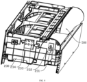
FIG. 6 is a three-dimensional schematic diagram showing a direction in which the housing assembly is connected to the motor inFIG. 1 ; -
FIG. 7 is an enlarged schematic diagram of area E inFIG. 6 -
FIG. 8 is a three-dimensional schematic diagram showing another direction in which the housing assembly is connected to the motor inFIG. 1 ; and -
FIG. 9 is a three-dimensional schematic diagram of an air guide member inFIG. 4 . - 100 refers to housing, and 110 refers to end cover; 200 refers to frame, 210 refers to mounting cavity, 220 refers to third vent, 230 refers to surface frame, 231 refers to first vent, 232 refers to first flange, 233 refers to second vent, 234 refers to second flange, 240 refers to air outlet frame, and 241 refers to mounting box; 300 refers to air guide member, 310 refers to body portion, 320 refers to first connecting portion, and 330 refers to second connecting portion; 400 refers to accommodating cavity; 500 refers to air outlet; 600 refers to empty cavity; and 700 refers to motor.
- The embodiments of the present disclosure will be described in detail hereinafter. Examples of the embodiments are shown in the accompanying drawings. The same or similar reference numerals throughout the drawings denote the same or similar elements or elements having the same or similar functions. The embodiments described below with reference to the accompanying drawings are exemplary and are only intended to explain the present disclosure, but should not be understood as limiting the present disclosure.
- In the description of the present disclosure, it should be understood that the orientation or positional relationship indicated by the terms relating orientation description such as up, down, left, right, front, back and the like is based on the orientation or positional relationship shown in the drawings, only for the convenience of describing and simplifying the present disclosure, and does not indicate or imply that the indicated device or element must have a specific orientation, or be constructed and operated in a specific orientation. Therefore, the terms should not be construed as limiting the present disclosure.
- In the description of the present disclosure, the meaning of multiple refers to be more than two, and the above is understood to include this number. In the description of the present disclosure, if first, second and third are described, the descriptions are utilized for the purpose of distinguishing the technical features only, and cannot be understood as indicating or implying relative importance, or implicitly indicating the number of technical features indicated thereby, or implicitly indicating the order of technical features indicated thereby.
- In the description of the present disclosure, unless otherwise explicitly defined, words such as formed with, setting, connecting and installing should be understood in a broad sense, and those having ordinary skill in the art can reasonably determine the specific meanings of the above words in the present disclosure in combination with the specific contents of the technical solutions.
- In the related art, an air conditioner is provided with a driving device for driving parts. For example, an air outlet of the air conditioner is usually provided with an air deflector, and the air deflector is driven by a motor to swing, thereby changing a direction of an airflow. The motor driving the air deflector is usually located inside a closed space, so the airflow is difficult to enter. Heat generated by the motor needs to be transferred by other parts, and the heat dissipation efficiency is low, which affects a service life of the motor. To solve the above problems, the cold air at the air outlet of the air conditioner can be led into the mounting cavity to realize heat dissipation of the motor. However, the cold air flowing out of the mounting cavity may contact a housing of the air conditioner, resulting in the temperature drop of the housing to cause condensation.
- Based on this, the present disclosure provides a housing assembly for an air conditioner, which is provided with an air guide member separated from a housing. The air guide member can guide an airflow, and when a temperature of the airflow is low, a condensation phenomenon caused by low-temperature air contacting the housing of the air conditioner can be avoided. Different embodiments of the present disclosure will be described below with reference to the drawings.
- In some embodiments of the present disclosure, the housing assembly includes a
housing 100, an air deflector, aframe 200 and anair guide member 300. Thehousing 100 is located outside the housing assembly. Theframe 200 is connected to thehousing 100 and provided with amounting cavity 210 and anair outlet 500 communicated with themounting cavity 210. The air deflector is rotatably arranged at theair outlet 500, and themounting cavity 210 is utilized for mounting a motor which drives the air deflector to swing. Theair guide member 300 is connected to theframe 200 and formed with an air duct communicated with the mountingcavity 210. Theair guide member 300 is arranged separately from thehousing 100. - Referring to
FIG. 1 to FIG. 3 , theframe 200 in this embodiment is provided with the mountingcavity 210 and theair outlet 500. In an implementation, theframe 200 is a single part or a collection of multiple parts. And in an implementation, the mountingcavity 210 is formed inside the single part or among the multiple parts. A position of the mountingcavity 210 is determined by a position of themotor 700. Since the air deflector is mounted at theair outlet 500 of the housing assembly, themotor 700 driving the air deflector to swing and the corresponding mountingcavity 210 are also close to theair outlet 500 of the housing assembly, that is, located at a lower part ofFIG. 1 . The air deflector and themotor 700 and a corresponding fixing structure can all be selected according to the existing technology. - Referring to
FIG. 3 , athird vent 220 is arranged on or among the parts utilized to form the mountingcavity 210, and thethird vent 220 is utilized to allow air at theair outlet 500 to enter the mountingcavity 210, thus realizing air flow in the mountingcavity 210 and accelerating heat dissipation of themotor 700. - Referring to
FIG. 3 andFIG. 4 , theair guide member 300 is located inside the housing assembly and is provided with an air duct communicated with the mountingcavity 210. Theair guide member 300 is utilized for guiding the airflow flowing through the mountingcavity 210, so that the airflow can follow a required path and is avoided from contacting thehousing 100. - The
air guide member 300 is separated from thehousing 100. The "housing 100" in this embodiment refers to the part located outside the housing assembly, including but not limited to an end cover, a panel, and the like. In an implementation, thehousing 100 is a single part or a collection of multiple parts. Thehousing 100 is in contact with ambient normal temperature air during daily work, and if the temperature of thehousing 100 is lower than that of the ambient air, condensation is easily formed. In this embodiment, theair guide member 300 is separated from thehousing 100. Even if low-temperature air flows in theair guide member 300, the temperature of thehousing 100 can not be lowered due to contact with the cold air, so that condensation can be avoided. - It can be understood that the housing assembly in this embodiment can be applied to both an indoor unit of a split air conditioner and an integrated air conditioner.
- In this embodiment, the housing assembly is provided with the mounting
cavity 210 for mounting themotor 700 and the mountingcavity 210 is communicated with theair outlet 500 of the housing assembly, so that the cold air at theair outlet 500 can enter the mountingcavity 210 to realize rapid heat dissipation. In another embodiment, the housing assembly is provided with theair guide member 300 to guide the airflow flowing through the mountingcavity 210. Combined with the separate arrangement of theair guide member 300 and thehousing 100, a condensation phenomenon caused by the cooling of thehousing 100 can be avoided. - Referring to
FIG. 4 to FIG. 7 , in some embodiments of the present disclosure, the housing assembly is provided with anaccommodating cavity 400 for accommodating an evaporator. One end of the air duct in theair guide member 300 is communicated with the mountingcavity 210, and the other end of the air duct is communicated with theaccommodating cavity 400. - In an embodiment, the
frame 200 is provided with athird vent 220. In this embodiment, thethird vent 220 serves as an air inlet of the mountingcavity 210, and the mountingcavity 210 is communicated with theair outlet 500 of the housing assembly through thethird vent 220. Theair guide member 300 is utilized to guide the airflow flowing out of the mountingcavity 210. One end of theair guide member 300 is communicated with the air outlet of the mountingcavity 210, and the other end of theair guide member 300 is communicated with theaccommodating cavity 400 of the housing assembly for accommodating the evaporator of the air conditioner. When the housing assembly of this embodiment is applied to the air conditioner, the low-temperature air at the air outlet of the air conditioner enters the mountingcavity 210 through thethird vent 220, cools themotor 700, and then enters theaccommodating cavity 400 through theair guide member 300. That is, the low-temperature air at the air outlet can be utilized to dissipate heat in this embodiment, which is helpful to improve a heat dissipation effect, and the low-temperature air flowing out of the mountingcavity 210 can flow back to theaccommodating cavity 400, thus preventing the low-temperature air from contacting thehousing 100. - Referring to
FIG. 3 ,FIG. 6 and FIG. 7 , in some embodiments of the present disclosure, theframe 200 includes asurface frame 230 and anair outlet frame 240. Thesurface frame 230 and theair outlet frame 240 define the mountingcavity 210. Athird vent 220 is formed between thesurface frame 230 and theair outlet frame 240, and the mountingcavity 210 is communicated with theair outlet 500 through thethird vent 220. - In this embodiment, the
frame 200 includes thesurface frame 230 and theair outlet frame 240, which define the mountingcavity 210. Thethird vent 220 is formed between thesurface frame 230 and theair outlet frame 240. In an implementation, one side of the air outlet frame 240 (for example, the lower left side inFIG. 7 ) is provided with a mountingbox 241, and one side of the mounting box 241 (for example, the left side inFIG. 7 ) is provided with an opening. When connecting, the mountingcavity 210 can be defined by making the opening side of the mountingbox 241 face thesurface frame 230 and making the mountingbox 241 close to but not contacting thesurface frame 230, and a gap between the mountingbox 241 and thesurface frame 230 is thethird vent 220. In this embodiment, the slender gap between thesurface frame 230 and theair outlet frame 240 is utilized as thethird vent 220, which can prevent a user from touching an internal motor on the premise of meeting ventilation requirements. At the same time, it is not necessary to separately process thethird vent 220 on thesurface frame 230 and theair outlet frame 240, which helps to reduce the processing cost. - In some embodiments of the present disclosure, the housing assembly includes a
surface frame 230 and anair outlet frame 240. Thesurface frame 230 and theair outlet frame 240 define a mountingcavity 210. Theair outlet frame 240 is provided with athird vent 220, and the mountingcavity 210 is communicated with theair outlet 500 through thethird vent 220. - In this embodiment, the
frame 200 includes thesurface frame 230 and theair outlet frame 240, which define the mountingcavity 210, and thethird vent 220 is formed on theair outlet frame 240 alone. For example, in an implementation, one side of the air outlet frame 240 (for example, the lower left side inFIG. 7 ) is provided with a mountingbox 241, and one side of the mounting box 241 (for example, the left side inFIG. 7 ) is provided with an opening. When connecting, the mountingcavity 210 can be defined by fitting the opening side of the mountingbox 241 with thesurface frame 230, and thethird vent 220 can be formed on a box wall of the mountingbox 241, so that thesurface frame 230 and theair outlet frame 240 can form an integrated structure, or thesurface frame 230 and theair outlet frame 240 can be connected by a fastener after fitting, and meanwhile, thethird vent 220 is arranged on theair outlet frame 240 closer to the air outlet of the air conditioner, which facilitates air intake. - Referring to
FIG. 3 , in some embodiments of the present disclosure, the housing assembly includes asurface frame 230 and anend cover 110. Theend cover 110 is connected to thesurface frame 230, and anair guide member 300 is located between theend cover 110 and thesurface frame 230, and is separately arranged from theend cover 110. - In this embodiment, the
frame 200 includes asurface frame 230, and thehousing 100 includes theend cover 110. Theend cover 110 is connected to the outside of thesurface frame 230. And usually, theend cover 110 and thesurface frame 230 define anempty cavity 600. Theair guide member 300 is mounted inside theempty cavity 600, which can make full use of the existing space of the housing assembly. Theair guide member 300 is not in contact with theend cover 110, which can avoid theend cover 110 from condensation. - In some embodiments of the present disclosure, the
air guide member 300 is detachably connected to theframe 200, so that theair guide member 300 can be replaced after ageing. In an implementation, theair guide member 300 can be connected to theframe 200 by a fastener or a buckle structure, and can also be connected to theframe 200 by an adhesive tape. - Referring to
FIG. 8 andFIG. 9 , in some embodiments of the present disclosure, theframe 200 is provided with afirst vent 231, afirst flange 232, asecond vent 233 and asecond flange 234. Thefirst flange 232 surrounds thefirst vent 231, and thesecond flange 234 surrounds thesecond vent 233. Theair guide member 300 includes a first connectingportion 320, abody portion 310 and a second connectingportion 330 which are connected in sequence. The first connectingportion 320 is sleeved on thefirst flange 232, so that the air duct of theair guide member 300 is communicated with the mountingcavity 210 through thefirst vent 231, and the second connectingportion 330 is sleeved on thesecond flange 234, so that the air duct of theair guide member 300 is communicated with theaccommodating cavity 400 through thesecond vent 233, thus realizing quick disassembly between theair guide member 300 and theframe 200. - Similarly, taking the
surface frame 230 as theframe 200 as an example, thesurface frame 230 is formed with thefirst vent 231 and thefirst flange 232. Thefirst vent 231 leads to the mountingcavity 210, and thefirst flange 232 surrounds an outside of thefirst vent 231 along a circular track or a square track. A shape of the first connectingportion 320 is adapted to a shape of thefirst flange 232, such as a square structure inFIG. 9 . In an implementation, the first connectingportion 320 can be an elastic structure made of rubber, silica gel and other materials. When in use, the first connectingportion 320 is stretched and sleeved outside thefirst flange 232, and the first connectingportion 320 can be tightly connected to thefirst flange 232 after contracting. When dismounting, the first connectingportion 320 can be separated only by pulling, which is simple to operate. - In another embodiment, the other end of the
air guide member 300 can also be connected to thesurface frame 230 in a similar way. In an implementation, thesurface frame 230 is formed with asecond vent 233 and asecond flange 234. Thesecond vent 233 leads to theaccommodating cavity 400 where the evaporator is placed, and thesecond flange 234 surrounds an outside of thesecond vent 233 along a circular track or a square track. Theair guide member 300 includes a second connectingportion 330. The second connectingportion 330, themain body portion 310 and the first connectingportion 320 are connected in sequence, and a shape of the second connectingportion 330 is adapted to a shape of thesecond flange 234, such as a square structure inFIG. 9 . In an implementation, the second connectingportion 330 can also be an elastic structure made of rubber, silica gel and other materials, and the second connectingportion 330 can be connected by being sleeved outside thesecond flange 234. - It can be understood that the shapes of the first connecting
portion 320 and the second connectingportion 330 are not limited to the shapes described in above embodiments. In some embodiments, the shapes of the first connectingportion 320, the second connectingportion 330 and thebody portion 310 can also be the same. For example, theair guide member 300 is an air guide pipe with a constant cross section, and both ends of the air guide pipe are utilized as the first connectingportion 320 and the second connectingportion 330 respectively. - Referring to
FIG. 8 , the frame is provided with a plurality of thefirst vents 231 and a plurality of the second vents 233. Thefirst flange 232 surrounds outside of the plurality of thefirst vents 231 and thesecond flange 234 surrounds outside the plurality of the second vents 233. - Taking the
surface frame 230 as theframe 200 as an example, thesurface frame 230 is provided with a plurality of thefirst vents 231 and a plurality of the second vents 233. Correspondingly, thefirst flange 232 surrounds the plurality of thefirst vents 231 and thesecond flange 234 surrounds the plurality of thesecond vents 233, so that the strength of thesurface frame 230 can be increased through the arrangement of this embodiment under the same vent hole area compared with that of a single vent hole. It can be understood that numbers of thefirst vent 231 and thesecond vent 233 are not limited in this embodiment, and can be two, three, four or other numbers. - In some embodiments of the present disclosure, the
body portion 310 of theair guide member 300 can be a hose tube made of rubber, silica gel, and the like, so that theair guide member 300 can be bent and mounted conveniently. In an embodiment, other parts of theair guide member 300, such as the first connectingportion 320 and the second connectingportion 330, can be made of the same material as thebody portion 310, that is, theair guide member 300 has an integrated structure. In another embodiment, the materials of the first connectingportion 320 and the second connectingportion 330 can also be different from the material of thebody portion 310, for example, thebody portion 310 has a flexible structure, and the first connectingportion 320 and the second connectingportion 330 have a rigid structure. - In some embodiments of the present disclosure, an indoor unit of an air conditioner is proposed. The indoor unit of the air conditioner includes the housing assembly of the above embodiments, and the
motor 700 for driving the air deflector to rotate on the indoor unit of the air conditioner is located in the mountingcavity 210. When a fan of the indoor unit of the air conditioner drives cold air to be discharged from theair outlet 500, the fan can also drive the cold air to enter the mountingcavity 210, thus realizing rapid heat dissipation of themotor 700. - This embodiment is applied to various air conditioners with indoor units, such as wall-mounted air conditioners, cabinet air conditioners, ceiling air conditioners, and the like.
- In the embodiment, as shown in
FIG. 3 , the body portion of themotor 700 is fixed inside the mountingcavity 210, and a driving shaft of themotor 700 is directly or indirectly connected to the air deflector (not shown in the figure) outside the mountingcavity 210 through a shaft sleeve and other structures, which can not only avoid touching the motor by the user, but also can drive the air deflector. - The fan is located inside the
housing 100 for forcing airflow into the mountingcavity 210. This embodiment can adopt the existing fan of the indoor unit of the air conditioner to form an airflow for heat dissipation, which is favorable for reducing the cost. The fan and a corresponding fixing structure can both be selected according to the existing technology. - In some embodiments of the present disclosure, an air conditioner is proposed, including the indoor unit of the air conditioner according to various embodiments described above.
- The embodiments of the present disclosure have been described in detail above with reference to the drawings, but the present disclosure is not limited to the above embodiments, and various changes can be made without departing from the purpose of the present disclosure within the scope of knowledge possessed by those having ordinary skill in the art.
Claims (10)
- A housing assembly for an air conditioner, comprising:a housing;an air deflector;a frame connected to the housing, and provided with a mounting cavity and an air outlet communicated with the mounting cavity, wherein the air deflector is rotatably arranged at the air outlet, and the mounting cavity is utilized for mounting a motor which drives the air deflector to swing; andan air guide member connected to the frame and formed with an air duct communicated with the mounting cavity, wherein the air guide member is arranged separately from the housing.
- The housing assembly for the air conditioner according to claim 1, wherein the frame is provided with an accommodating cavity utilized for accommodating an evaporator, one end of the air duct is communicated with the mounting cavity, and the other end of the air duct is communicated with the accommodating cavity.
- The housing assembly for the air conditioner according to claim 2, wherein the air guide member is detachably connected to the frame.
- The housing assembly for the air conditioner according to claim 3, wherein:the frame is provided with a first vent, a first flange, a second vent and a second flange, the first flange surrounds the first vent and the second flange surrounds the second vent;the air guide member comprises a first connecting portion, a body portion and a second connecting portion which are connected in sequence;the first connecting portion is sleeved on the first flange, so that the air duct is communicated with the mounting cavity through the first vent; andthe second connecting portion is sleeved on the second flange, so that the air duct is communicated with the accommodating cavity through the second vent.
- The housing assembly for the air conditioner according to claim 4, wherein the frame is provided with a plurality of the first vents and a plurality of the second vents, the first flange surrounds the plurality of the first vents, and the second flange surrounds the plurality of the second vents.
- The housing assembly for the air conditioner according to claim 4, wherein the body portion is a hose tube.
- The housing assembly for the air conditioner according to claim 2, wherein:
the frame comprises a surface frame and an air outlet frame, and the surface frame and the air outlet frame define the mounting cavity, wherein:a third vent is formed between the surface frame and the air outlet frame, and the mounting cavity is communicated with the air outlet through the third vent;or, the air outlet frame is provided with a third vent, and the mounting cavity is communicated with the air outlet through the third vent. - The housing assembly for the air conditioner according to claim 1, wherein the housing comprises an end cover, the frame comprises a surface frame, the end cover is connected to the surface frame, the air guide member is located between the end cover and the surface frame, and is arranged separately from the end cover.
- An indoor unit of an air conditioner, comprising the housing assembly for the air conditioner according to any one of claims 1 to 8.
- An air conditioner, comprising the indoor unit of the air conditioner according to claim 9.
Applications Claiming Priority (2)
| Application Number | Priority Date | Filing Date | Title |
|---|---|---|---|
| CN202021507270.9U CN212619205U (en) | 2020-07-27 | 2020-07-27 | Shell assembly for air conditioner, air conditioner indoor unit and air conditioner |
| PCT/CN2020/126772 WO2022021654A1 (en) | 2020-07-27 | 2020-11-05 | Housing assembly for air conditioner, indoor unit of air conditioner, and air conditioner |
Publications (4)
| Publication Number | Publication Date |
|---|---|
| EP4163569A1 true EP4163569A1 (en) | 2023-04-12 |
| EP4163569A4 EP4163569A4 (en) | 2023-11-15 |
| EP4163569C0 EP4163569C0 (en) | 2024-10-23 |
| EP4163569B1 EP4163569B1 (en) | 2024-10-23 |
Family
ID=74729123
Family Applications (1)
| Application Number | Title | Priority Date | Filing Date |
|---|---|---|---|
| EP20947445.1A Active EP4163569B1 (en) | 2020-07-27 | 2020-11-05 | Housing assembly for air conditioner, indoor unit of air conditioner, and air conditioner |
Country Status (3)
| Country | Link |
|---|---|
| EP (1) | EP4163569B1 (en) |
| CN (1) | CN212619205U (en) |
| WO (1) | WO2022021654A1 (en) |
Family Cites Families (6)
| Publication number | Priority date | Publication date | Assignee | Title |
|---|---|---|---|---|
| JP5817391B2 (en) * | 2011-09-28 | 2015-11-18 | 株式会社富士通ゼネラル | Air conditioner |
| CN104697052B (en) * | 2015-02-13 | 2018-03-09 | 广东美的制冷设备有限公司 | Air conditioner room unit and its control method |
| CN208046356U (en) * | 2018-05-04 | 2018-11-02 | Tcl空调器(中山)有限公司 | Motor gland and air conditioner |
| CN209181107U (en) * | 2018-11-08 | 2019-07-30 | 广州华凌制冷设备有限公司 | Air conditioner indoor unit and air conditioner with it |
| CN110030623A (en) * | 2019-04-30 | 2019-07-19 | 广东美的制冷设备有限公司 | Air conditioner indoor unit and its control method |
| CN210861619U (en) * | 2019-10-29 | 2020-06-26 | 广东美的制冷设备有限公司 | Air deflector assembly of air conditioner and air conditioner with same |
-
2020
- 2020-07-27 CN CN202021507270.9U patent/CN212619205U/en active Active
- 2020-11-05 WO PCT/CN2020/126772 patent/WO2022021654A1/en not_active Ceased
- 2020-11-05 EP EP20947445.1A patent/EP4163569B1/en active Active
Also Published As
| Publication number | Publication date |
|---|---|
| WO2022021654A1 (en) | 2022-02-03 |
| CN212619205U (en) | 2021-02-26 |
| EP4163569A4 (en) | 2023-11-15 |
| EP4163569C0 (en) | 2024-10-23 |
| EP4163569B1 (en) | 2024-10-23 |
Similar Documents
| Publication | Publication Date | Title |
|---|---|---|
| EP1607690A1 (en) | Air conditioner | |
| WO2022052714A1 (en) | Air conditioner indoor unit and air conditioner | |
| CN205980017U (en) | Indoor unit and air conditioner with same | |
| CN210273758U (en) | Heat dissipation mechanism of frequency conversion all-in-one machine | |
| CN208046356U (en) | Motor gland and air conditioner | |
| CN211011643U (en) | Integral air conditioner | |
| CN106765848B (en) | Integrated fresh air exchanging air conditioner | |
| EP4163569A1 (en) | Housing assembly for air conditioner, indoor unit of air conditioner, and air conditioner | |
| CN217209590U (en) | Outdoor unit of air conditioner | |
| CN210832222U (en) | Air conditioner indoor unit and air conditioner | |
| CN209639137U (en) | Duct machine | |
| CN206234913U (en) | Through-flow air-conditioner | |
| CN218915116U (en) | Indoor unit of air conditioner and air conditioner | |
| CN218846303U (en) | air conditioner | |
| CN217540890U (en) | Indoor machine of air conditioner | |
| EP4350228B1 (en) | Air conditioner indoor unit | |
| CN115751482A (en) | Air conditioner | |
| CN211261057U (en) | window air conditioner | |
| CN209672686U (en) | Air quantity controller and refrigeration equipment | |
| CN210164670U (en) | Centrifugal scavenger fan | |
| CN222322012U (en) | Backboard assembly and display device | |
| CN209558553U (en) | The heat exchanger components and air conditioner indoor unit of air conditioner indoor unit | |
| CN220911605U (en) | Adjustable refrigerating machine room ventilation system | |
| CN208332618U (en) | A kind of central air-conditioning air deflection assemblies | |
| CN209541114U (en) | A wiring structure of an indoor unit and an air conditioner |
Legal Events
| Date | Code | Title | Description |
|---|---|---|---|
| STAA | Information on the status of an ep patent application or granted ep patent |
Free format text: STATUS: THE INTERNATIONAL PUBLICATION HAS BEEN MADE |
|
| PUAI | Public reference made under article 153(3) epc to a published international application that has entered the european phase |
Free format text: ORIGINAL CODE: 0009012 |
|
| STAA | Information on the status of an ep patent application or granted ep patent |
Free format text: STATUS: REQUEST FOR EXAMINATION WAS MADE |
|
| 17P | Request for examination filed |
Effective date: 20230109 |
|
| AK | Designated contracting states |
Kind code of ref document: A1 Designated state(s): AL AT BE BG CH CY CZ DE DK EE ES FI FR GB GR HR HU IE IS IT LI LT LU LV MC MK MT NL NO PL PT RO RS SE SI SK SM TR |
|
| DAV | Request for validation of the european patent (deleted) | ||
| DAX | Request for extension of the european patent (deleted) | ||
| A4 | Supplementary search report drawn up and despatched |
Effective date: 20231017 |
|
| RIC1 | Information provided on ipc code assigned before grant |
Ipc: F24F 1/0057 20190101ALI20231011BHEP Ipc: F24F 1/0011 20190101ALI20231011BHEP Ipc: F24F 13/14 20060101ALI20231011BHEP Ipc: F24F 13/22 20060101ALI20231011BHEP Ipc: F24F 13/20 20060101AFI20231011BHEP |
|
| GRAP | Despatch of communication of intention to grant a patent |
Free format text: ORIGINAL CODE: EPIDOSNIGR1 |
|
| STAA | Information on the status of an ep patent application or granted ep patent |
Free format text: STATUS: GRANT OF PATENT IS INTENDED |
|
| INTG | Intention to grant announced |
Effective date: 20240607 |
|
| GRAS | Grant fee paid |
Free format text: ORIGINAL CODE: EPIDOSNIGR3 |
|
| GRAA | (expected) grant |
Free format text: ORIGINAL CODE: 0009210 |
|
| STAA | Information on the status of an ep patent application or granted ep patent |
Free format text: STATUS: THE PATENT HAS BEEN GRANTED |
|
| AK | Designated contracting states |
Kind code of ref document: B1 Designated state(s): AL AT BE BG CH CY CZ DE DK EE ES FI FR GB GR HR HU IE IS IT LI LT LU LV MC MK MT NL NO PL PT RO RS SE SI SK SM TR |
|
| REG | Reference to a national code |
Ref country code: GB Ref legal event code: FG4D |
|
| REG | Reference to a national code |
Ref country code: CH Ref legal event code: EP |
|
| REG | Reference to a national code |
Ref country code: DE Ref legal event code: R096 Ref document number: 602020040111 Country of ref document: DE |
|
| REG | Reference to a national code |
Ref country code: IE Ref legal event code: FG4D |
|
| U01 | Request for unitary effect filed |
Effective date: 20241106 |
|
| U07 | Unitary effect registered |
Designated state(s): AT BE BG DE DK EE FI FR IT LT LU LV MT NL PT RO SE SI Effective date: 20241114 |
|
| U20 | Renewal fee for the european patent with unitary effect paid |
Year of fee payment: 5 Effective date: 20241122 |
|
| PG25 | Lapsed in a contracting state [announced via postgrant information from national office to epo] |
Ref country code: HR Free format text: LAPSE BECAUSE OF FAILURE TO SUBMIT A TRANSLATION OF THE DESCRIPTION OR TO PAY THE FEE WITHIN THE PRESCRIBED TIME-LIMIT Effective date: 20241023 Ref country code: IS Free format text: LAPSE BECAUSE OF FAILURE TO SUBMIT A TRANSLATION OF THE DESCRIPTION OR TO PAY THE FEE WITHIN THE PRESCRIBED TIME-LIMIT Effective date: 20250223 |
|
| PG25 | Lapsed in a contracting state [announced via postgrant information from national office to epo] |
Ref country code: ES Free format text: LAPSE BECAUSE OF FAILURE TO SUBMIT A TRANSLATION OF THE DESCRIPTION OR TO PAY THE FEE WITHIN THE PRESCRIBED TIME-LIMIT Effective date: 20241023 |
|
| PG25 | Lapsed in a contracting state [announced via postgrant information from national office to epo] |
Ref country code: NO Free format text: LAPSE BECAUSE OF FAILURE TO SUBMIT A TRANSLATION OF THE DESCRIPTION OR TO PAY THE FEE WITHIN THE PRESCRIBED TIME-LIMIT Effective date: 20250123 |
|
| PG25 | Lapsed in a contracting state [announced via postgrant information from national office to epo] |
Ref country code: GR Free format text: LAPSE BECAUSE OF FAILURE TO SUBMIT A TRANSLATION OF THE DESCRIPTION OR TO PAY THE FEE WITHIN THE PRESCRIBED TIME-LIMIT Effective date: 20250124 |
|
| PG25 | Lapsed in a contracting state [announced via postgrant information from national office to epo] |
Ref country code: PL Free format text: LAPSE BECAUSE OF FAILURE TO SUBMIT A TRANSLATION OF THE DESCRIPTION OR TO PAY THE FEE WITHIN THE PRESCRIBED TIME-LIMIT Effective date: 20241023 |
|
| PG25 | Lapsed in a contracting state [announced via postgrant information from national office to epo] |
Ref country code: RS Free format text: LAPSE BECAUSE OF FAILURE TO SUBMIT A TRANSLATION OF THE DESCRIPTION OR TO PAY THE FEE WITHIN THE PRESCRIBED TIME-LIMIT Effective date: 20250123 |
|
| REG | Reference to a national code |
Ref country code: CH Ref legal event code: PL |
|
| PG25 | Lapsed in a contracting state [announced via postgrant information from national office to epo] |
Ref country code: SM Free format text: LAPSE BECAUSE OF FAILURE TO SUBMIT A TRANSLATION OF THE DESCRIPTION OR TO PAY THE FEE WITHIN THE PRESCRIBED TIME-LIMIT Effective date: 20241023 |
|
| PG25 | Lapsed in a contracting state [announced via postgrant information from national office to epo] |
Ref country code: MC Free format text: LAPSE BECAUSE OF FAILURE TO SUBMIT A TRANSLATION OF THE DESCRIPTION OR TO PAY THE FEE WITHIN THE PRESCRIBED TIME-LIMIT Effective date: 20241023 |
|
| REG | Reference to a national code |
Ref country code: CH Ref legal event code: PL |
|
| PG25 | Lapsed in a contracting state [announced via postgrant information from national office to epo] |
Ref country code: CH Free format text: LAPSE BECAUSE OF NON-PAYMENT OF DUE FEES Effective date: 20241130 |
|
| PG25 | Lapsed in a contracting state [announced via postgrant information from national office to epo] |
Ref country code: SK Free format text: LAPSE BECAUSE OF FAILURE TO SUBMIT A TRANSLATION OF THE DESCRIPTION OR TO PAY THE FEE WITHIN THE PRESCRIBED TIME-LIMIT Effective date: 20241023 |
|
| PG25 | Lapsed in a contracting state [announced via postgrant information from national office to epo] |
Ref country code: CZ Free format text: LAPSE BECAUSE OF FAILURE TO SUBMIT A TRANSLATION OF THE DESCRIPTION OR TO PAY THE FEE WITHIN THE PRESCRIBED TIME-LIMIT Effective date: 20241023 |
|
| PLBE | No opposition filed within time limit |
Free format text: ORIGINAL CODE: 0009261 |
|
| STAA | Information on the status of an ep patent application or granted ep patent |
Free format text: STATUS: NO OPPOSITION FILED WITHIN TIME LIMIT |
|
| GBPC | Gb: european patent ceased through non-payment of renewal fee |
Effective date: 20250123 |
|
| 26N | No opposition filed |
Effective date: 20250724 |
|
| PG25 | Lapsed in a contracting state [announced via postgrant information from national office to epo] |
Ref country code: GB Free format text: LAPSE BECAUSE OF NON-PAYMENT OF DUE FEES Effective date: 20250123 |
|
| PG25 | Lapsed in a contracting state [announced via postgrant information from national office to epo] |
Ref country code: IE Free format text: LAPSE BECAUSE OF NON-PAYMENT OF DUE FEES Effective date: 20241105 |
|
| U20 | Renewal fee for the european patent with unitary effect paid |
Year of fee payment: 6 Effective date: 20251127 |
|
| PG25 | Lapsed in a contracting state [announced via postgrant information from national office to epo] |
Ref country code: HU Free format text: LAPSE BECAUSE OF FAILURE TO SUBMIT A TRANSLATION OF THE DESCRIPTION OR TO PAY THE FEE WITHIN THE PRESCRIBED TIME-LIMIT; INVALID AB INITIO Effective date: 20201105 |
|
| PG25 | Lapsed in a contracting state [announced via postgrant information from national office to epo] |
Ref country code: CY Free format text: LAPSE BECAUSE OF FAILURE TO SUBMIT A TRANSLATION OF THE DESCRIPTION OR TO PAY THE FEE WITHIN THE PRESCRIBED TIME-LIMIT; INVALID AB INITIO Effective date: 20201105 |
|
| U1N | Appointed representative for the unitary patent procedure changed after the registration of the unitary effect |
Representative=s name: TREEBY, PHILIP DAVID WILLIAM; GB |