EP4163565A1 - A near field communication device and system for attachment to an outdoor unit housing - Google Patents
A near field communication device and system for attachment to an outdoor unit housing Download PDFInfo
- Publication number
- EP4163565A1 EP4163565A1 EP22199195.3A EP22199195A EP4163565A1 EP 4163565 A1 EP4163565 A1 EP 4163565A1 EP 22199195 A EP22199195 A EP 22199195A EP 4163565 A1 EP4163565 A1 EP 4163565A1
- Authority
- EP
- European Patent Office
- Prior art keywords
- near field
- mobile device
- housing
- radio antenna
- outdoor unit
- Prior art date
- Legal status (The legal status is an assumption and is not a legal conclusion. Google has not performed a legal analysis and makes no representation as to the accuracy of the status listed.)
- Granted
Links
Images


Classifications
-
- F—MECHANICAL ENGINEERING; LIGHTING; HEATING; WEAPONS; BLASTING
- F24—HEATING; RANGES; VENTILATING
- F24F—AIR-CONDITIONING; AIR-HUMIDIFICATION; VENTILATION; USE OF AIR CURRENTS FOR SCREENING
- F24F11/00—Control or safety arrangements
- F24F11/50—Control or safety arrangements characterised by user interfaces or communication
- F24F11/56—Remote control
-
- H—ELECTRICITY
- H04—ELECTRIC COMMUNICATION TECHNIQUE
- H04B—TRANSMISSION
- H04B5/00—Near-field transmission systems, e.g. inductive or capacitive transmission systems
- H04B5/70—Near-field transmission systems, e.g. inductive or capacitive transmission systems specially adapted for specific purposes
- H04B5/72—Near-field transmission systems, e.g. inductive or capacitive transmission systems specially adapted for specific purposes for local intradevice communication
-
- F—MECHANICAL ENGINEERING; LIGHTING; HEATING; WEAPONS; BLASTING
- F24—HEATING; RANGES; VENTILATING
- F24F—AIR-CONDITIONING; AIR-HUMIDIFICATION; VENTILATION; USE OF AIR CURRENTS FOR SCREENING
- F24F1/00—Room units for air-conditioning, e.g. separate or self-contained units or units receiving primary air from a central station
- F24F1/06—Separate outdoor units, e.g. outdoor unit to be linked to a separate room comprising a compressor and a heat exchanger
- F24F1/20—Electric components for separate outdoor units
- F24F1/22—Arrangement or mounting thereof
-
- H—ELECTRICITY
- H04—ELECTRIC COMMUNICATION TECHNIQUE
- H04B—TRANSMISSION
- H04B5/00—Near-field transmission systems, e.g. inductive or capacitive transmission systems
- H04B5/20—Near-field transmission systems, e.g. inductive or capacitive transmission systems characterised by the transmission technique; characterised by the transmission medium
-
- H—ELECTRICITY
- H04—ELECTRIC COMMUNICATION TECHNIQUE
- H04B—TRANSMISSION
- H04B5/00—Near-field transmission systems, e.g. inductive or capacitive transmission systems
- H04B5/70—Near-field transmission systems, e.g. inductive or capacitive transmission systems specially adapted for specific purposes
- H04B5/75—Near-field transmission systems, e.g. inductive or capacitive transmission systems specially adapted for specific purposes for isolation purposes
-
- H—ELECTRICITY
- H04—ELECTRIC COMMUNICATION TECHNIQUE
- H04B—TRANSMISSION
- H04B5/00—Near-field transmission systems, e.g. inductive or capacitive transmission systems
- H04B5/40—Near-field transmission systems, e.g. inductive or capacitive transmission systems characterised by components specially adapted for near-field transmission
- H04B5/45—Transponders
-
- Y—GENERAL TAGGING OF NEW TECHNOLOGICAL DEVELOPMENTS; GENERAL TAGGING OF CROSS-SECTIONAL TECHNOLOGIES SPANNING OVER SEVERAL SECTIONS OF THE IPC; TECHNICAL SUBJECTS COVERED BY FORMER USPC CROSS-REFERENCE ART COLLECTIONS [XRACs] AND DIGESTS
- Y02—TECHNOLOGIES OR APPLICATIONS FOR MITIGATION OR ADAPTATION AGAINST CLIMATE CHANGE
- Y02B—CLIMATE CHANGE MITIGATION TECHNOLOGIES RELATED TO BUILDINGS, e.g. HOUSING, HOUSE APPLIANCES OR RELATED END-USER APPLICATIONS
- Y02B30/00—Energy efficient heating, ventilation or air conditioning [HVAC]
- Y02B30/70—Efficient control or regulation technologies, e.g. for control of refrigerant flow, motor or heating
Definitions
- the invention relates to a near field communication device for a heating, ventilation, and air conditioning (HVAC) system.
- HVAC heating, ventilation, and air conditioning
- HVAC is the technology of indoor and vehicular environmental comfort and is an important part of residential, industrial and commercial structures.
- the heating process in HVAC systems provides for increases in indoor temperatures while the air conditioning process provides for decreases in indoor temperatures.
- the ventilation processes involves exchanges or replacements of air in a space to thus provide for high indoor air quality with temperature control, oxygen replenishment and removal of moisture, odors, smoke, heat, dust, airborne bacteria, carbon dioxide and other gases. Ventilation includes both the exchange of indoor and outdoor air as well as the circulation of air within a building.
- Home-based HVAC systems typically include an outdoor unit, an indoor unit, a thermostat and one or more sensors in some cases.
- the thermostat is usually accessible to the homeowner who uses the thermostat to set a desired temperature for an indoor space in a home.
- the thermostat then operates the outdoor and indoor units so as to achieve that desired temperature in a manner that also reduces costs and energy usage as much as possible.
- the thermostat will command the outdoor and indoor units to pump heated air into the indoor space so as to raise the temperature of the indoor space beyond the desired temperature by a predetermined degree.
- the thermostat will command the outdoor and indoor units to pump cool air into the indoor space so as to lower the temperature of the indoor space beyond the desired temperature by a predetermined degree.
- a near field communication device for a heat, ventilation, and air conditioning (HVAC) system.
- the near field communication device including: a near field radio antenna configured to detect and transmit near field communication wireless signals, wherein the near field radio antenna is configured to be attached to a housing of an outdoor unit of the HVAC system; a near field transceiver configured to communicate with a mobile device through the near field radio antenna; and a controller configured to be in electronic communication with an outdoor controller of the outdoor unit.
- the system may include a communication cable configured to connect the near field communication device to the outdoor controller, wherein the controller is in electronic communication with the outdoor controller through the communication cable.
- the near field radio antenna is configured to be attached to or located proximate to an inner surface of the housing of the outdoor unit or an outer surface of the housing of the outdoor unit.
- the system may include a mobile device cradle configured to be attached to the housing of the outdoor unit, the mobile device cradle being configured to support the mobile device, wherein the near field radio antenna is embedded in or attached to the mobile device cradle.
- the mobile device cradle is configured to be attached to an outer surface of the housing.
- the mobile device cradle further includes a support surface where the mobile device may be placed on to wirelessly connect to the near field radio antenna.
- the near field radio antenna is embedded in the support surface.
- the mobile device cradle may further include at least one of: a first side guard extending away from the support surface, the first side guard being configured to prevent the mobile device from sliding laterally off the support surface; a second side guard extending away from the support surface and located opposite the first side guard, the second side guard being configured to prevent the mobile device from sliding laterally off the support surface; and a bottom guard extending away from the support surface, the bottom guard being configured to prevent the mobile device from sliding vertically off the support surface.
- a system for wireless connection between a mobile device and a heat, ventilation, and air conditioning (HVAC) system includes: an HVAC system including an outdoor unit including: an outdoor controller: and a housing having an inner surface and an outer surface; and a near field communication device including: a near field radio antenna configured to detect and transmit near field communication wireless signals, wherein the near field radio antenna is attached to the housing of the outdoor unit of the HVAC system; a near field transceiver configured to communicate with the mobile device through the near field radio antenna; and a controller configured to be in electronic communication with the outdoor controller of the outdoor unit.
- HVAC heat, ventilation, and air conditioning
- the near field communication device may be as described above.
- the system may include a communication cable configured to connect the near field communication device to the outdoor controller, wherein the controller is in electronic communication with the outdoor controller through the communication cable.
- the near field radio antenna is attached to the inner surface of the housing of the outdoor unit.
- the near field radio antenna is located proximate to the inner surface of the housing of the outdoor unit.
- the near field radio antenna is attached to the outer surface of the housing of the outdoor unit.
- the near field radio antenna is located proximate to the outer surface of the housing of the outdoor unit.
- the near field communication device further includes: a mobile device cradle configured to be attached to the housing of the outdoor unit, the mobile device cradle being configured to support the mobile device, wherein the near field radio antenna is embedded in or attached to the mobile device cradle.
- the mobile device cradle is attached to the outer surface of the housing.
- the mobile device cradle further includes a support surface where the mobile device may be placed on to wirelessly connect to the near field radio antenna.
- the near field radio antenna is embedded in the support surface.
- the mobile device cradle further includes at least one of: a first side guard extending away from the support surface, the first side guard being configured to prevent the mobile device from sliding laterally off the support surface; a second side guard extending away from the support surface and located opposite the first side guard, the second side guard being configured to prevent the mobile device from sliding laterally off the support surface; and a bottom guard extending away from the support surface, the bottom guard being configured to prevent the mobile device from sliding vertically off the support surface.
- the housing includes a marking to indicate where a user should place or locate their mobile device on the outer surface of the housing.
- inventions of the present disclosure include placing a near field radio antenna in an area of the easily accessible to a mechanic such that a mechanic may easily connect to the HVAC system through near field communication.
- HVAC heating, ventilation and air-conditioning
- the HVAC system may include an outdoor unit disposed at an exterior of the structure and an indoor unit disposed at an interior of the structure.
- Various operations of the outdoor and indoor units are controllable to maintain desired environmental conditions in the interior of the structure using a thermostat in wireless communication with one or more sensors spread throughout the structure.
- Embodiments disclosed herein seek to provide a short range wireless communication method and system for a mobile device to communicate with the outdoor unit.
- FIG. 1 is schematic view of a structure 10 and an HVAC system 20 for the structure 10.
- the structure 10 may be configured as a residence, an industrial building, or a commercial building. For purposes of clarity and brevity, however, the following description will relate to the case where the structure 10 is configured as a single-family residence.
- the structure 10 thus includes a structural body 11 which defines an interior 12 and separates the interior 12 from an exterior 13.
- the interior 12 may be further divided into multiple rooms 14 and areas for various purposes.
- the structure 10 includes an HVAC system 20 disposed and configured to control environmental conditions within the interior 12.
- the HVAC system 20 includes one or more of an outdoor unit 21 and an indoor unit 22.
- the outdoor unit 21 is disposed at the exterior 13 of the structural body 11 and the indoor unit 22 is disposed in the interior 12.
- the outdoor unit 21 includes a condenser coil 210, a compressor 211, a fan 212 and, in some cases, an outdoor controller 213, and a first wireless transceiver 214.
- the first wireless transceiver 214 may be in wireless communication with a thermostat 300.
- the outdoor unit 21 may be in wired communication with the thermostat 300.
- the outdoor controller 213 may be an electronic controller including a processor 216 and an associated memory 218 comprising computer-executable instructions (i.e., computer program product) that, when executed by the processor 216, cause the processor 216 to perform various operations.
- the processor 216 may be, but is not limited to, a single-processor or multi-processor system of any of a wide array of possible architectures, including field programmable gate array (FPGA), central processing unit (CPU), application specific integrated circuits (ASIC), digital signal processor (DSP) or graphics processing unit (GPU) hardware arranged homogenously or heterogeneously.
- the memory 218 may be but is not limited to a random access memory (RAM), read only memory (ROM), or other electronic, optical, magnetic or any other computer readable medium.
- the indoor unit 22 includes an indoor coil 220, a furnace 221 and, in some cases, an indoor controller 222 and a second wireless transceiver 223.
- the second wireless transceiver 223 may be in wireless communication with a thermostat 300.
- the indoor unit 22 may be in wired communication with the thermostat 300.
- the second wireless transceiver 223 may also be in wireless communication with the first wireless transceiver 214.
- the indoor controller 222 may be an electronic controller including a processor 226 and an associated memory 228 comprising computer-executable instructions (i.e., computer program product) that, when executed by the processor 226, cause the processor 226 to perform various operations.
- the processor 226 may be, but is not limited to, a single-processor or multi-processor system of any of a wide array of possible architectures, including field programmable gate array (FPGA), central processing unit (CPU), application specific integrated circuits (ASIC), digital signal processor (DSP) or graphics processing unit (GPU) hardware arranged homogenously or heterogeneously.
- the memory 228 may be but is not limited to a random access memory (RAM), read only memory (ROM), or other electronic, optical, magnetic or any other computer readable medium.
- Refrigeration lines 23 are provided to connect the outdoor unit 21 with the indoor unit 22 and ducts 24 are provided throughout the interior 12 such that heated or cooled air can be transported from the indoor unit 22 to the various areas in the interior 12. It is understood that while FIG. 1 illustrated a particular arrangement of ducts 24, the embodiments disclosed herein may apply to any arrangement of ducts 24.
- the components of the outdoor unit 21 and the indoor unit 22 may be included in a single unit that can be disposed at the exterior 13 of the structural body 11 or in the interior 12.
- the components of the indoor unit 22 may be included in the outdoor unit 21 and disposed at the exterior 13.
- the components of the outdoor unit 21 may be included in the indoor unit 22 and disposed in the interior 12.
- the HVAC system 20 may further include one or more sensors 700, such as temperature sensors, that are distributed throughout the interior 12 and possibly at the exterior 13.
- the sensors 700 are in wireless or wired communication with the thermostat 300, a further discussed herein.
- the thermostat 300 is generally accessible to an individual and is configured to control various operations of the outdoor unit 21 and indoor unit 22 to maintain desired environmental conditions in the interior 12 in accordance with at least readings of the one or more sensors 700 and with commands input by a user.
- the thermostat 300 may have the capability to establish and maintain wireless connectivity over one or more networks (e.g., Wi-Fi, Bluetooth, Z-Wave, Zigbee, etc.).
- the thermostat 300 can therefore be connected to a homeowner's Wi-Fi network and the Internet. This allows the thermostat 300 to have additional features and capabilities including, but not limited to, being remotely controllable by a user using a portable computing device (e.g., a mobile phone, a tablet, a laptop, etc.).
- the HVAC system 20 may further include a near field communication device 500 in wired or wireless communication with the outdoor controller 213.
- the near field communication device 500 includes a near field radio antenna configured to communicate with a mobile device 400 using near field communication.
- the outdoor unit 21 includes a housing 26 that houses or contains the outdoor unit 21.
- the housing 26 protects the outdoor unit 21 from the outside environment.
- the housing 26 may include an outer surface 28 and an inner surface 30.
- the communicating device in order to communicate with a near field device such as near field device 500, the communicating device must be in close proximity to the near field device.
- a user such as a mechanic typically may remove a housing 26 and in some circumstances remove other components in order to place a communications device in close proximity to the near field device 500.
- the near field radio antenna 520 (shown in FIG. 2 ) may be located within a housing 26 of the outdoor unit 21 attached to or proximate to an inner surface 30 of the housing 26, such that near field communications may be transmitted between the near field radio antenna 520 and the mobile device 400 through the housing 26.
- the near field radio antenna 520 may be located outside of the housing 26 attached to or proximate to an outer surface 28 of the housing 26.
- FIG. 2 a block diagram of a near field communication system 100 for wireless connection between the mobile device 400 and the HVAC system 20 is illustrated. It should be appreciated that, although particular systems are separately defined in the schematic block diagrams, each or any of the systems may be otherwise combined or separated via hardware and/or software.
- the near field communication device 500 includes a controller 510, a near field radio antenna 520, a near field transceiver 530, a processor 512, a memory 514, a communication cable 550 and a power supply 540.
- the near field radio antenna 520 is configured to detect and transmit near field communication wireless signals.
- a near field transceiver 530 is configured to communicate with a mobile device 400 through the near field radio antenna 520.
- the near field transceiver 530 is configured to transmit and receive data through the near field radio antenna 520 to and from a communication device 440 of the mobile device 400.
- the near field transceiver 530 may be capable of wireless communication including but not limitation to a near field communication (i.e., NFC), or another short-range wireless transmission method.
- the near field radio antenna 520 is any antenna appropriate to the near field transceiver 530.
- the power supply 540 is a power source such as a power cable, a power scavenging system, power generation system, or a battery that powers the near field communication device 500.
- the controller 510 may be an electronic controller including a processor 512 and an associated memory 514 comprising computer-executable instructions (i.e., computer program product) that, when executed by the processor 512, cause the processor 512 to perform various operations.
- the processor 512 may be, but is not limited to, a single-processor or multi-processor system of any of a wide array of possible architectures, including field programmable gate array (FPGA), central processing unit (CPU), application specific integrated circuits (ASIC), digital signal processor (DSP) or graphics processing unit (GPU) hardware arranged homogenously or heterogeneously.
- the memory 514 may be but is not limited to a random access memory (RAM), read only memory (ROM), or other electronic, optical, magnetic or any other computer readable medium.
- the controller 510 is configured to be in electronic communication with the outdoor controller 213.
- the controller 510 may in wired or wireless communications with the outdoor controller 213.
- the communication cable 550 may be a hardline cable that is configured to connect the near field communication device 500 to the outdoor controller 213 so that the near field communication device 500 may communicate with the outdoor controller 213.
- the outdoor controller 213 is configured to communicate with the mobile device 400 through the near field communication device 500 and the mobile device 400 is configured to communicate with the outdoor controller 213 through the near field communication device 500.
- the near field communication device 500 may include serial communications 560, which may be the communication standards for communications with the mobile device 400 and the outdoor controller 231.
- the mobile device 400 may be a mobile computing device that is typically carried by a person, such as, for example a phone, a smart phone, a PDA, a smart watch, a tablet, a laptop, or any other mobile computing device known to one of skill in the art.
- the mobile device 400 includes a controller 410 configured to control operations of the mobile device 400.
- the controller 410 may be an electronic controller including a processor 430 and an associated memory 420 comprising computer-executable instructions (i.e., computer program product) that, when executed by the processor 430, cause the processor 430 to perform various operations.
- the processor 430 may be, but is not limited to, a single-processor or multi-processor system of any of a wide array of possible architectures, including field programmable gate array (FPGA), central processing unit (CPU), application specific integrated circuits (ASIC), digital signal processor (DSP) or graphics processing unit (GPU) hardware arranged homogenously or heterogeneously.
- the memory 420 may be but is not limited to a random access memory (RAM), read only memory (ROM), or other electronic, optical, magnetic or any other computer readable medium.
- the mobile device 400 includes a communication device 440 configured to communicate with the near field radio antenna 520 through one or more wireless signals.
- the one or more wireless signals may be near field communications or any other short range wireless communication known to one of skill in the art.
- the mobile device 400 is configured to communicate with the outdoor controller 213 through the near field communication device 500.
- the mobile device 400 may include a display device 480, such as for example a computer display, an LCD display, an LED display, an OLED display, a touchscreen of a smart phone, or any other similar display device known to one of the skill in the art.
- a user operating the mobile device 400 is able to view an application 450 through the display device 480.
- the application 450 may allow the user to program the HVAC system 20, communicate with the HVAC system 20, update firmware of the HVAC system 20, view operational data of the HVAC system 20, and/or send commands to the HVAC system 20.
- the mobile device 400 includes an input device 470 configured to receive a manual input from a user (e.g., human being) of mobile device 400.
- the input device 470 may be a keyboard, a touch screen, a joystick, a knob, a touchpad, one or more physical buttons, a microphone configured to receive a voice command, a camera or sensor configured to receive a gesture command, an inertial measurement unit configured to detect a shake of the mobile device 400, or any similar input device known to one of skill in the art.
- the user operating the mobile device 400 is able to enter feedback into the application 450 through the input device 470.
- the input device 470 allows the user operating the mobile device 400 to enter feedback into the application 450 via a manual input to input device 470.
- the user may respond to a prompt on the display device 480 by entering a manual input via the input device 470.
- the manual input may be a touch on the touchscreen.
- the display device 480 and the input device 470 may be combined into a single device, such as, for example, a touchscreen.
- the user may be able to view operational data of the HVAC system 20 through the display device 480 of the mobile device 400 when the mobile device 400 is in communication with the outdoor controller 213 through the near field communication device 500.
- the user may be able to troubleshoot the HVAC system 20 and send commands to the HVAC system 20 through the input device 470 of the mobile device 400 when the mobile device 400 is in communication with the outdoor controller 213 through the near field communication device 500.
- the mobile device 400 device may also include a feedback device 460.
- the feedback device 460 may activate in response to a manual input via the input device 470.
- the feedback device 460 may be a haptic feedback vibration device and/or a speaker emitting a sound.
- the feedback device 460 device may activate to confirm that the manual input entered via the input device 470 was received via the application 450.
- the feedback device 460 device may activate by emitting an audible sound or vibrate the mobile device 400 to confirm that the manual input entered via the input device 470 was received via the application 450.
- the near field radio antenna 520 may be located within a housing 26 of the outdoor unit 21 attached to or proximate to an inner surface 30 of the housing 26, such that near field communications may be transmitted between the near field radio antenna 520 and the mobile device 400 through the housing 26.
- the housing 26 includes a top wall 26a and one or more side wall 26b.
- the near field radio antenna 520 may be located within a housing 26 of the outdoor unit 21 attached to or proximate to the top wall 26a or the side wall 26b.
- the mobile device 400 may need to be laid flat on the outer surface 28 of the housing 26 in order for the communication device 440 of the mobile device 400 to connect through near field communication with the near field radio antenna 520.
- the outer surface 28 of the housing 26 may include a marking 700 to indicate where a user should place or locate their mobile device 400 on the outer surface 28.
- the marking 700 may be an emblem, logo, symbol, text, pictograph, pictograph, ideogram, or any similar marking.
- the marking 700 may be attached the housing 26 (e.g., sticker or decal on the outer surface 28), etched into the housing 26, printed onto the outer surface 28 of the housing 26, embedded into the housing 26, embossed into the housing 26, stamped into the housing 26, or applied to the housing 26 using any other method known to one of skill in the art.
- FIG. 3 a block diagram of a near field communication system 100 for wireless connection between the mobile device 400 and the near field communication device 500 is illustrated. It should be appreciated that, although particular systems are separately defined in the schematic block diagrams, each or any of the systems may be otherwise combined or separated via hardware and/or software.
- FIG. 3 illustrates an alternative embodiment, where the near field radio antenna 520 may be located outside of the housing 26 attached to or proximate to an outer surface 28 of the housing 26.
- the near field radio antenna 520 is embedded in or attached to a mobile device cradle 600 that is configured to support the mobile device 400.
- the mobile device cradle 600 is configured to support or hold a mobile device 400.
- the mobile device cradle 600 includes a support surface 610 where the mobile device 400 may be placed on to wirelessly connect to the near field radio antenna 520.
- the near field radio antenna 520 may be embedded in the support surface 610.
- the support surface 610 may include a marking 710 to indicate where a user should place or locate their mobile device 400 on the support surface 610.
- the marking 710 may be an emblem, logo, symbol, text, pictograph, pictograph, ideogram, or any similar marking.
- the marking 710 may be attached the housing 26 (e.g., sticker or decal on the support surface 610), etched into the support surface 610, printed onto the support surface 610, embedded into the support surface 610, embossed into the support surface 610, stamped into the support surface 610, or applied to the support surface 610 using any other method known to one of skill in the art.
- the mobile device cradle 600 may include a first side guard 620 and a second side guard 630 located opposite the first side guard 620.
- the first side guard 620 and second side guard 630 are configured to prevent the mobile device 400 from sliding laterally off the support surface 610.
- the first side guard 620 and the second side guard 630 extend away from the support surface 610.
- the mobile device cradle 600 may also include one or more bottom guards 640 configured to prevent the mobile device 400 from sliding vertically off the support surface 610.
- the one or more bottom guards 640 extend away from the support surface 610.
- the mobile device cradle 600 is configured to attach to the housing 26.
- the mobile device cradle 600 may be configured to attach to the outer surface 28 of the housing 26 or the inner surface 30 of the housing 26.
- the mobile device cradle 600 may be configured to attach to the top wall 26a or the side wall 26b.
- the mobile device cradle 600 may be attached directly to the housing 26 or through a support structure 660.
- the near field radio antenna 520 is connected to the near field transceiver 530 through a wired connection 670.
- the mobile device cradle 600 may be composed of a weatherproof polyimide or a similar material known to one of skill in the art.
- the mobile device cradle 600 provides an easily accessible and clearly visible spot for a mechanic/user to place their phone and connect to the HVAC system 20 in order to run diagnostics, troubleshoot, program, update firmware, and/or communicate with the HVAC system 20.
- embodiments can be in the form of processor-implemented processes and devices for practicing those processes, such as processor.
- Embodiments can also be in the form of computer program code (e.g., computer program product) containing instructions embodied in tangible media (e.g., non-transitory computer readable medium), such as floppy diskettes, CD ROMs, hard drives, or any other non-transitory computer readable medium, wherein, when the computer program code is loaded into and executed by a computer, the computer becomes a device for practicing the embodiments.
- Embodiments can also be in the form of computer program code, for example, whether stored in a storage medium, loaded into and/or executed by a computer, or transmitted over some transmission medium, such as over electrical wiring or cabling, through fiber optics, or via electromagnetic radiation, wherein, when the computer program code is loaded into and executed by a computer, the computer becomes a device for practicing the exemplary embodiments.
- the computer program code segments configure the microprocessor to create specific logic circuits.
Landscapes
- Engineering & Computer Science (AREA)
- Computer Networks & Wireless Communication (AREA)
- Signal Processing (AREA)
- Chemical & Material Sciences (AREA)
- Combustion & Propulsion (AREA)
- Mechanical Engineering (AREA)
- General Engineering & Computer Science (AREA)
- Human Computer Interaction (AREA)
- Air Conditioning Control Device (AREA)
Abstract
Description
- The invention relates to a near field communication device for a heating, ventilation, and air conditioning (HVAC) system.
- HVAC is the technology of indoor and vehicular environmental comfort and is an important part of residential, industrial and commercial structures. The heating process in HVAC systems provides for increases in indoor temperatures while the air conditioning process provides for decreases in indoor temperatures. The ventilation processes involves exchanges or replacements of air in a space to thus provide for high indoor air quality with temperature control, oxygen replenishment and removal of moisture, odors, smoke, heat, dust, airborne bacteria, carbon dioxide and other gases. Ventilation includes both the exchange of indoor and outdoor air as well as the circulation of air within a building.
- Home-based HVAC systems typically include an outdoor unit, an indoor unit, a thermostat and one or more sensors in some cases. The thermostat is usually accessible to the homeowner who uses the thermostat to set a desired temperature for an indoor space in a home. The thermostat then operates the outdoor and indoor units so as to achieve that desired temperature in a manner that also reduces costs and energy usage as much as possible. To this end, if the temperature in the indoor space is lower than the desired temperature by a predetermined degree, the thermostat will command the outdoor and indoor units to pump heated air into the indoor space so as to raise the temperature of the indoor space beyond the desired temperature by a predetermined degree. On the other hand, if the temperature in the indoor space is higher than the desired temperature by a predetermined degree, the thermostat will command the outdoor and indoor units to pump cool air into the indoor space so as to lower the temperature of the indoor space beyond the desired temperature by a predetermined degree.
- According to one embodiment, a near field communication device for a heat, ventilation, and air conditioning (HVAC) system is provided. The near field communication device including: a near field radio antenna configured to detect and transmit near field communication wireless signals, wherein the near field radio antenna is configured to be attached to a housing of an outdoor unit of the HVAC system; a near field transceiver configured to communicate with a mobile device through the near field radio antenna; and a controller configured to be in electronic communication with an outdoor controller of the outdoor unit.
- The system may include a communication cable configured to connect the near field communication device to the outdoor controller, wherein the controller is in electronic communication with the outdoor controller through the communication cable.
- Optionally the near field radio antenna is configured to be attached to or located proximate to an inner surface of the housing of the outdoor unit or an outer surface of the housing of the outdoor unit.
- The system may include a mobile device cradle configured to be attached to the housing of the outdoor unit, the mobile device cradle being configured to support the mobile device, wherein the near field radio antenna is embedded in or attached to the mobile device cradle.
- Optionally, the mobile device cradle is configured to be attached to an outer surface of the housing.
- Optionally, the mobile device cradle further includes a support surface where the mobile device may be placed on to wirelessly connect to the near field radio antenna.
- Optionally, the near field radio antenna is embedded in the support surface.
- The mobile device cradle may further include at least one of: a first side guard extending away from the support surface, the first side guard being configured to prevent the mobile device from sliding laterally off the support surface; a second side guard extending away from the support surface and located opposite the first side guard, the second side guard being configured to prevent the mobile device from sliding laterally off the support surface; and a bottom guard extending away from the support surface, the bottom guard being configured to prevent the mobile device from sliding vertically off the support surface.
- According to another embodiment, a system for wireless connection between a mobile device and a heat, ventilation, and air conditioning (HVAC) system is provided. The system includes: an HVAC system including an outdoor unit including: an outdoor controller: and a housing having an inner surface and an outer surface; and a near field communication device including: a near field radio antenna configured to detect and transmit near field communication wireless signals, wherein the near field radio antenna is attached to the housing of the outdoor unit of the HVAC system; a near field transceiver configured to communicate with the mobile device through the near field radio antenna; and a controller configured to be in electronic communication with the outdoor controller of the outdoor unit.
- The near field communication device may be as described above.
- The system may include a communication cable configured to connect the near field communication device to the outdoor controller, wherein the controller is in electronic communication with the outdoor controller through the communication cable.
- Optionally, the near field radio antenna is attached to the inner surface of the housing of the outdoor unit.
- Optionally, the near field radio antenna is located proximate to the inner surface of the housing of the outdoor unit.
- Optionally, the near field radio antenna is attached to the outer surface of the housing of the outdoor unit.
- Optionally, the near field radio antenna is located proximate to the outer surface of the housing of the outdoor unit.
- Optionally, the near field communication device further includes: a mobile device cradle configured to be attached to the housing of the outdoor unit, the mobile device cradle being configured to support the mobile device, wherein the near field radio antenna is embedded in or attached to the mobile device cradle.
- Optionally, the mobile device cradle is attached to the outer surface of the housing.
- Optionally, the mobile device cradle further includes a support surface where the mobile device may be placed on to wirelessly connect to the near field radio antenna.
- Optionally, the near field radio antenna is embedded in the support surface.
- Optionally, the mobile device cradle further includes at least one of: a first side guard extending away from the support surface, the first side guard being configured to prevent the mobile device from sliding laterally off the support surface; a second side guard extending away from the support surface and located opposite the first side guard, the second side guard being configured to prevent the mobile device from sliding laterally off the support surface; and a bottom guard extending away from the support surface, the bottom guard being configured to prevent the mobile device from sliding vertically off the support surface.
- Optionally the housing includes a marking to indicate where a user should place or locate their mobile device on the outer surface of the housing.
- Technical effects of embodiments of the present disclosure include placing a near field radio antenna in an area of the easily accessible to a mechanic such that a mechanic may easily connect to the HVAC system through near field communication.
- The foregoing features and elements may be combined in various combinations without exclusivity, unless expressly indicated otherwise. These features and elements as well as the operation thereof will become more apparent in light of the following description and the accompanying drawings. It should be understood, however, that the following description and drawings are intended to be illustrative and explanatory in nature and non-limiting.
- The following descriptions should not be considered limiting in any way. With reference to the accompanying drawings, like elements are numbered alike:
-
FIG. 1 is a perspective view of a structure in which a heating, ventilation and air-conditioning (HVAC) system is deployed; -
FIG. 2 is a block diagram of a near field communication system for wireless connection between a mobile device and the HVAC system; and -
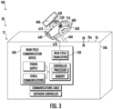
FIG. 3 is a block diagram of a near field communication system for wireless connection between a mobile device and the HVAC system. - A detailed description of one or more embodiments of the disclosed apparatus and method are presented herein by way of exemplification and not limitation with reference to the Figures.
- As will be described below, a heating, ventilation and air-conditioning (HVAC) system for a structure is provided. The HVAC system may include an outdoor unit disposed at an exterior of the structure and an indoor unit disposed at an interior of the structure. Various operations of the outdoor and indoor units are controllable to maintain desired environmental conditions in the interior of the structure using a thermostat in wireless communication with one or more sensors spread throughout the structure. Embodiments disclosed herein seek to provide a short range wireless communication method and system for a mobile device to communicate with the outdoor unit.
-
FIG. 1 is schematic view of astructure 10 and anHVAC system 20 for thestructure 10. Thestructure 10 may be configured as a residence, an industrial building, or a commercial building. For purposes of clarity and brevity, however, the following description will relate to the case where thestructure 10 is configured as a single-family residence. Thestructure 10 thus includes astructural body 11 which defines aninterior 12 and separates theinterior 12 from anexterior 13. Theinterior 12 may be further divided intomultiple rooms 14 and areas for various purposes. - The
structure 10 includes anHVAC system 20 disposed and configured to control environmental conditions within theinterior 12. TheHVAC system 20 includes one or more of anoutdoor unit 21 and anindoor unit 22. Theoutdoor unit 21 is disposed at theexterior 13 of thestructural body 11 and theindoor unit 22 is disposed in theinterior 12. - As shown in
FIG. 1 , theoutdoor unit 21 includes acondenser coil 210, acompressor 211, afan 212 and, in some cases, anoutdoor controller 213, and a firstwireless transceiver 214. The firstwireless transceiver 214 may be in wireless communication with athermostat 300. Alternatively, theoutdoor unit 21 may be in wired communication with thethermostat 300. Theoutdoor controller 213 may be an electronic controller including aprocessor 216 and an associatedmemory 218 comprising computer-executable instructions (i.e., computer program product) that, when executed by theprocessor 216, cause theprocessor 216 to perform various operations. Theprocessor 216 may be, but is not limited to, a single-processor or multi-processor system of any of a wide array of possible architectures, including field programmable gate array (FPGA), central processing unit (CPU), application specific integrated circuits (ASIC), digital signal processor (DSP) or graphics processing unit (GPU) hardware arranged homogenously or heterogeneously. Thememory 218 may be but is not limited to a random access memory (RAM), read only memory (ROM), or other electronic, optical, magnetic or any other computer readable medium. - As shown in
FIG. 1 , theindoor unit 22 includes anindoor coil 220, afurnace 221 and, in some cases, anindoor controller 222 and a secondwireless transceiver 223. The secondwireless transceiver 223 may be in wireless communication with athermostat 300. Alternatively, theindoor unit 22 may be in wired communication with thethermostat 300. The secondwireless transceiver 223 may also be in wireless communication with the firstwireless transceiver 214. Theindoor controller 222 may be an electronic controller including aprocessor 226 and an associatedmemory 228 comprising computer-executable instructions (i.e., computer program product) that, when executed by theprocessor 226, cause theprocessor 226 to perform various operations. Theprocessor 226 may be, but is not limited to, a single-processor or multi-processor system of any of a wide array of possible architectures, including field programmable gate array (FPGA), central processing unit (CPU), application specific integrated circuits (ASIC), digital signal processor (DSP) or graphics processing unit (GPU) hardware arranged homogenously or heterogeneously. Thememory 228 may be but is not limited to a random access memory (RAM), read only memory (ROM), or other electronic, optical, magnetic or any other computer readable medium. -
Refrigeration lines 23 are provided to connect theoutdoor unit 21 with theindoor unit 22 andducts 24 are provided throughout the interior 12 such that heated or cooled air can be transported from theindoor unit 22 to the various areas in the interior 12. It is understood that whileFIG. 1 illustrated a particular arrangement ofducts 24, the embodiments disclosed herein may apply to any arrangement ofducts 24. - In some cases, the components of the
outdoor unit 21 and theindoor unit 22 may be included in a single unit that can be disposed at theexterior 13 of thestructural body 11 or in the interior 12. For example, the components of theindoor unit 22 may be included in theoutdoor unit 21 and disposed at theexterior 13. Conversely, the components of theoutdoor unit 21 may be included in theindoor unit 22 and disposed in the interior 12. Still other embodiments exist in which the components of theoutdoor unit 21 andindoor unit 22 are included in a single device which is partially disposed at the exterior 13 and partially disposed in the interior 12 (e.g., a window air-conditioning unit or wall air conditioning unit). - The
HVAC system 20 may further include one ormore sensors 700, such as temperature sensors, that are distributed throughout the interior 12 and possibly at theexterior 13. Thesensors 700 are in wireless or wired communication with thethermostat 300, a further discussed herein. Thethermostat 300 is generally accessible to an individual and is configured to control various operations of theoutdoor unit 21 andindoor unit 22 to maintain desired environmental conditions in the interior 12 in accordance with at least readings of the one ormore sensors 700 and with commands input by a user. - The
thermostat 300 may have the capability to establish and maintain wireless connectivity over one or more networks (e.g., Wi-Fi, Bluetooth, Z-Wave, Zigbee, etc.). Thethermostat 300 can therefore be connected to a homeowner's Wi-Fi network and the Internet. This allows thethermostat 300 to have additional features and capabilities including, but not limited to, being remotely controllable by a user using a portable computing device (e.g., a mobile phone, a tablet, a laptop, etc.). - The
HVAC system 20 may further include a nearfield communication device 500 in wired or wireless communication with theoutdoor controller 213. The nearfield communication device 500 includes a near field radio antenna configured to communicate with amobile device 400 using near field communication. Theoutdoor unit 21 includes ahousing 26 that houses or contains theoutdoor unit 21. Thehousing 26 protects theoutdoor unit 21 from the outside environment. Thehousing 26 may include anouter surface 28 and aninner surface 30. - Typically, in order to communicate with a near field device such as
near field device 500, the communicating device must be in close proximity to the near field device. In an HVAC system a user such as a mechanic typically may remove ahousing 26 and in some circumstances remove other components in order to place a communications device in close proximity to thenear field device 500. In order to allow a user to communicate with thenear field device 500 without removing thehousing 26 and/or other components, the near field radio antenna 520 (shown inFIG. 2 ) may be located within ahousing 26 of theoutdoor unit 21 attached to or proximate to aninner surface 30 of thehousing 26, such that near field communications may be transmitted between the nearfield radio antenna 520 and themobile device 400 through thehousing 26. Alternatively, the nearfield radio antenna 520 may be located outside of thehousing 26 attached to or proximate to anouter surface 28 of thehousing 26. - Referring now to
FIG. 2 , with continued reference toFIG. 1 , a block diagram of a nearfield communication system 100 for wireless connection between themobile device 400 and theHVAC system 20 is illustrated. It should be appreciated that, although particular systems are separately defined in the schematic block diagrams, each or any of the systems may be otherwise combined or separated via hardware and/or software. - The near
field communication device 500 includes acontroller 510, a nearfield radio antenna 520, anear field transceiver 530, aprocessor 512, amemory 514, acommunication cable 550 and apower supply 540. - The near
field radio antenna 520 is configured to detect and transmit near field communication wireless signals. Anear field transceiver 530 is configured to communicate with amobile device 400 through the nearfield radio antenna 520. Thenear field transceiver 530 is configured to transmit and receive data through the nearfield radio antenna 520 to and from acommunication device 440 of themobile device 400. Thenear field transceiver 530 may be capable of wireless communication including but not limitation to a near field communication (i.e., NFC), or another short-range wireless transmission method. The nearfield radio antenna 520 is any antenna appropriate to thenear field transceiver 530. Thepower supply 540 is a power source such as a power cable, a power scavenging system, power generation system, or a battery that powers the nearfield communication device 500. - The
controller 510 may be an electronic controller including aprocessor 512 and an associatedmemory 514 comprising computer-executable instructions (i.e., computer program product) that, when executed by theprocessor 512, cause theprocessor 512 to perform various operations. Theprocessor 512 may be, but is not limited to, a single-processor or multi-processor system of any of a wide array of possible architectures, including field programmable gate array (FPGA), central processing unit (CPU), application specific integrated circuits (ASIC), digital signal processor (DSP) or graphics processing unit (GPU) hardware arranged homogenously or heterogeneously. Thememory 514 may be but is not limited to a random access memory (RAM), read only memory (ROM), or other electronic, optical, magnetic or any other computer readable medium. - The
controller 510 is configured to be in electronic communication with theoutdoor controller 213. Thecontroller 510 may in wired or wireless communications with theoutdoor controller 213. - The
communication cable 550 may be a hardline cable that is configured to connect the nearfield communication device 500 to theoutdoor controller 213 so that the nearfield communication device 500 may communicate with theoutdoor controller 213. Theoutdoor controller 213 is configured to communicate with themobile device 400 through the nearfield communication device 500 and themobile device 400 is configured to communicate with theoutdoor controller 213 through the nearfield communication device 500. The nearfield communication device 500 may includeserial communications 560, which may be the communication standards for communications with themobile device 400 and the outdoor controller 231. - The
mobile device 400 may be a mobile computing device that is typically carried by a person, such as, for example a phone, a smart phone, a PDA, a smart watch, a tablet, a laptop, or any other mobile computing device known to one of skill in the art. Themobile device 400 includes acontroller 410 configured to control operations of themobile device 400. Thecontroller 410 may be an electronic controller including aprocessor 430 and an associatedmemory 420 comprising computer-executable instructions (i.e., computer program product) that, when executed by theprocessor 430, cause theprocessor 430 to perform various operations. Theprocessor 430 may be, but is not limited to, a single-processor or multi-processor system of any of a wide array of possible architectures, including field programmable gate array (FPGA), central processing unit (CPU), application specific integrated circuits (ASIC), digital signal processor (DSP) or graphics processing unit (GPU) hardware arranged homogenously or heterogeneously. Thememory 420 may be but is not limited to a random access memory (RAM), read only memory (ROM), or other electronic, optical, magnetic or any other computer readable medium. - The
mobile device 400 includes acommunication device 440 configured to communicate with the nearfield radio antenna 520 through one or more wireless signals. The one or more wireless signals may be near field communications or any other short range wireless communication known to one of skill in the art. Themobile device 400 is configured to communicate with theoutdoor controller 213 through the nearfield communication device 500. - The
mobile device 400 may include adisplay device 480, such as for example a computer display, an LCD display, an LED display, an OLED display, a touchscreen of a smart phone, or any other similar display device known to one of the skill in the art. A user operating themobile device 400 is able to view anapplication 450 through thedisplay device 480. - The
application 450 may allow the user to program theHVAC system 20, communicate with theHVAC system 20, update firmware of theHVAC system 20, view operational data of theHVAC system 20, and/or send commands to theHVAC system 20. - The
mobile device 400 includes aninput device 470 configured to receive a manual input from a user (e.g., human being) ofmobile device 400. Theinput device 470 may be a keyboard, a touch screen, a joystick, a knob, a touchpad, one or more physical buttons, a microphone configured to receive a voice command, a camera or sensor configured to receive a gesture command, an inertial measurement unit configured to detect a shake of themobile device 400, or any similar input device known to one of skill in the art. The user operating themobile device 400 is able to enter feedback into theapplication 450 through theinput device 470. Theinput device 470 allows the user operating themobile device 400 to enter feedback into theapplication 450 via a manual input toinput device 470. For example, the user may respond to a prompt on thedisplay device 480 by entering a manual input via theinput device 470. In one example, the manual input may be a touch on the touchscreen. In an embodiment, thedisplay device 480 and theinput device 470 may be combined into a single device, such as, for example, a touchscreen. - The user may be able to view operational data of the
HVAC system 20 through thedisplay device 480 of themobile device 400 when themobile device 400 is in communication with theoutdoor controller 213 through the nearfield communication device 500. The user may be able to troubleshoot theHVAC system 20 and send commands to theHVAC system 20 through theinput device 470 of themobile device 400 when themobile device 400 is in communication with theoutdoor controller 213 through the nearfield communication device 500. - The
mobile device 400 device may also include afeedback device 460. Thefeedback device 460 may activate in response to a manual input via theinput device 470. Thefeedback device 460 may be a haptic feedback vibration device and/or a speaker emitting a sound. Thefeedback device 460 device may activate to confirm that the manual input entered via theinput device 470 was received via theapplication 450. For example, thefeedback device 460 device may activate by emitting an audible sound or vibrate themobile device 400 to confirm that the manual input entered via theinput device 470 was received via theapplication 450. - As aforementioned and illustrated in
FIG. 2 , the nearfield radio antenna 520 may be located within ahousing 26 of theoutdoor unit 21 attached to or proximate to aninner surface 30 of thehousing 26, such that near field communications may be transmitted between the nearfield radio antenna 520 and themobile device 400 through thehousing 26. Thehousing 26 includes atop wall 26a and one ormore side wall 26b. The nearfield radio antenna 520 may be located within ahousing 26 of theoutdoor unit 21 attached to or proximate to thetop wall 26a or theside wall 26b. - The
mobile device 400 may need to be laid flat on theouter surface 28 of thehousing 26 in order for thecommunication device 440 of themobile device 400 to connect through near field communication with the nearfield radio antenna 520. Theouter surface 28 of thehousing 26 may include a marking 700 to indicate where a user should place or locate theirmobile device 400 on theouter surface 28. The marking 700 may be an emblem, logo, symbol, text, pictograph, pictograph, ideogram, or any similar marking. The marking 700 may be attached the housing 26 (e.g., sticker or decal on the outer surface 28), etched into thehousing 26, printed onto theouter surface 28 of thehousing 26, embedded into thehousing 26, embossed into thehousing 26, stamped into thehousing 26, or applied to thehousing 26 using any other method known to one of skill in the art. - Referring now to
FIG. 3 , with continued reference toFIGS. 1-2 , a block diagram of a nearfield communication system 100 for wireless connection between themobile device 400 and the nearfield communication device 500 is illustrated. It should be appreciated that, although particular systems are separately defined in the schematic block diagrams, each or any of the systems may be otherwise combined or separated via hardware and/or software. -
FIG. 3 illustrates an alternative embodiment, where the nearfield radio antenna 520 may be located outside of thehousing 26 attached to or proximate to anouter surface 28 of thehousing 26. The nearfield radio antenna 520 is embedded in or attached to amobile device cradle 600 that is configured to support themobile device 400. - The
mobile device cradle 600 is configured to support or hold amobile device 400. Themobile device cradle 600 includes asupport surface 610 where themobile device 400 may be placed on to wirelessly connect to the nearfield radio antenna 520. The nearfield radio antenna 520 may be embedded in thesupport surface 610. - The
support surface 610 may include a marking 710 to indicate where a user should place or locate theirmobile device 400 on thesupport surface 610. The marking 710 may be an emblem, logo, symbol, text, pictograph, pictograph, ideogram, or any similar marking. The marking 710 may be attached the housing 26 (e.g., sticker or decal on the support surface 610), etched into thesupport surface 610, printed onto thesupport surface 610, embedded into thesupport surface 610, embossed into thesupport surface 610, stamped into thesupport surface 610, or applied to thesupport surface 610 using any other method known to one of skill in the art. - The
mobile device cradle 600 may include afirst side guard 620 and asecond side guard 630 located opposite thefirst side guard 620. Thefirst side guard 620 andsecond side guard 630 are configured to prevent themobile device 400 from sliding laterally off thesupport surface 610. Thefirst side guard 620 and thesecond side guard 630 extend away from thesupport surface 610. Themobile device cradle 600 may also include one or morebottom guards 640 configured to prevent themobile device 400 from sliding vertically off thesupport surface 610. The one or morebottom guards 640 extend away from thesupport surface 610. - The
mobile device cradle 600 is configured to attach to thehousing 26. Themobile device cradle 600 may be configured to attach to theouter surface 28 of thehousing 26 or theinner surface 30 of thehousing 26. Themobile device cradle 600 may be configured to attach to thetop wall 26a or theside wall 26b. - The
mobile device cradle 600 may be attached directly to thehousing 26 or through asupport structure 660. The nearfield radio antenna 520 is connected to thenear field transceiver 530 through awired connection 670. - The
mobile device cradle 600 may be composed of a weatherproof polyimide or a similar material known to one of skill in the art. Advantageously, themobile device cradle 600 provides an easily accessible and clearly visible spot for a mechanic/user to place their phone and connect to theHVAC system 20 in order to run diagnostics, troubleshoot, program, update firmware, and/or communicate with theHVAC system 20. - The terminology used herein is for the purpose of describing particular embodiments only and is not intended to be limiting of the present disclosure. As used herein, the singular forms "a", "an" and "the" are intended to include the plural forms as well, unless the context clearly indicates otherwise. It will be further understood that the terms "comprises" and/or "comprising," when used in this specification, specify the presence of stated features, integers, steps, operations, elements, and/or components, but do not preclude the presence or addition of one or more other features, integers, steps, operations, element components, and/or groups thereof.
- As described above, embodiments can be in the form of processor-implemented processes and devices for practicing those processes, such as processor. Embodiments can also be in the form of computer program code (e.g., computer program product) containing instructions embodied in tangible media (e.g., non-transitory computer readable medium), such as floppy diskettes, CD ROMs, hard drives, or any other non-transitory computer readable medium, wherein, when the computer program code is loaded into and executed by a computer, the computer becomes a device for practicing the embodiments. Embodiments can also be in the form of computer program code, for example, whether stored in a storage medium, loaded into and/or executed by a computer, or transmitted over some transmission medium, such as over electrical wiring or cabling, through fiber optics, or via electromagnetic radiation, wherein, when the computer program code is loaded into and executed by a computer, the computer becomes a device for practicing the exemplary embodiments. When implemented on a general-purpose microprocessor, the computer program code segments configure the microprocessor to create specific logic circuits.
- While the present disclosure has been described with reference to an exemplary embodiment or embodiments, it will be understood by those skilled in the art that various changes may be made and equivalents may be substituted for elements thereof without departing from the scope of the present invention, which is defined by the claims. In addition, many modifications may be made to adapt a particular situation or material to the teachings of the present disclosure. Therefore, it is intended that the present invention not be limited to the particular embodiment disclosed as the best mode contemplated for carrying out this present disclosure, but that the present invention will include all embodiments falling within the scope of the claims.
Claims (14)
- A near field communication device for a heat, ventilation, and air conditioning (HVAC) system, the near field communication device comprising:a near field radio antenna configured to detect and transmit near field communication wireless signals, wherein the near field radio antenna is configured to be attached to a housing of an outdoor unit of the HVAC system;a near field transceiver configured to communicate with a mobile device through the near field radio antenna; anda controller configured to be in electronic communication with an outdoor controller of the outdoor unit.
- The near field communication device of claim 1, further comprising:
a communication cable configured to connect the near field communication device to the outdoor controller, wherein the controller is in electronic communication with the outdoor controller through the communication cable. - The near field communication device of claim 1 or 2, wherein the near field radio antenna is configured to be attached to or located proximate to an inner surface of the housing of the outdoor unit or an outer surface of the housing of the outdoor unit.
- The near field communication device of claim 1, 2 or 3, further comprising:a mobile device cradle configured to be attached to the housing of the outdoor unit, the mobile device cradle being configured to support the mobile device,wherein the near field radio antenna is embedded in or attached to the mobile device cradle.
- The near field communication device of claim 4, wherein the mobile device cradle configured to be attached to an outer surface of the housing.
- The near field communication device of claim 4 or 5, wherein the mobile device cradle further comprises a support surface where the mobile device may be placed on to wirelessly connect to the near field radio antenna.
- The near field communication device of claim 6, wherein the near field radio antenna is embedded in the support surface.
- The near field communication device of claim 6 or 7, wherein the mobile device cradle further comprises at least one of:a first side guard extending away from the support surface, the first side guard being configured to prevent the mobile device from sliding laterally off the support surface;a second side guard extending away from the support surface and located opposite the first side guard, the second side guard being configured to prevent the mobile device from sliding laterally off the support surface; anda bottom guard extending away from the support surface, the bottom guard being configured to prevent the mobile device from sliding vertically off the support surface.
- A system for wireless connection between a mobile device and a heat, ventilation, and air conditioning (HVAC) system, the system comprising:an HVAC system comprising an outdoor unit comprising:an outdoor controller: anda housing having an inner surface and an outer surface; anda near field communication device as claimed in any preceding claim, wherein the near field radio antenna is attached to the housing of the outdoor unit of the HVAC system; the near field transceiver is configured to communicate with the mobile device through the near field radio antenna; and the controller is configured to be in electronic communication with the outdoor controller of the outdoor unit.
- The near field communication system of claim 9, wherein the near field radio antenna is attached to the inner surface of the housing of the outdoor unit.
- The near field communication system of claim 9 or 10, wherein the near field radio antenna is located proximate to the inner surface of the housing of the outdoor unit.
- The near field communication system of claim 9 or 10 wherein the near field radio antenna is attached to the outer surface of the housing of the outdoor unit.
- The near field communication system of claim 9 or 10, wherein the near field radio antenna is located proximate to the outer surface of the housing of the outdoor unit.
- The near field communication system of any of claims 9 to 13, wherein the housing includes a marking to indicate where a user should place or locate their mobile device on the outer surface of the housing.
Applications Claiming Priority (1)
| Application Number | Priority Date | Filing Date | Title |
|---|---|---|---|
| US202163252439P | 2021-10-05 | 2021-10-05 |
Publications (2)
| Publication Number | Publication Date |
|---|---|
| EP4163565A1 true EP4163565A1 (en) | 2023-04-12 |
| EP4163565B1 EP4163565B1 (en) | 2024-07-31 |
Family
ID=83902813
Family Applications (1)
| Application Number | Title | Priority Date | Filing Date |
|---|---|---|---|
| EP22199195.3A Active EP4163565B1 (en) | 2021-10-05 | 2022-09-30 | A near field communication device and system for attachment to an outdoor unit housing |
Country Status (3)
| Country | Link |
|---|---|
| US (1) | US12381597B2 (en) |
| EP (1) | EP4163565B1 (en) |
| CN (1) | CN115940998A (en) |
Families Citing this family (1)
| Publication number | Priority date | Publication date | Assignee | Title |
|---|---|---|---|---|
| US12405020B2 (en) * | 2022-06-07 | 2025-09-02 | Tyco Fire & Security Gmbh | HVAC connectivity control systems and methods |
Citations (3)
| Publication number | Priority date | Publication date | Assignee | Title |
|---|---|---|---|---|
| EP3222925A1 (en) * | 2014-11-18 | 2017-09-27 | Toshiba Carrier Corporation | Outdoor unit |
| EP3222927A1 (en) * | 2014-11-19 | 2017-09-27 | Toshiba Carrier Corporation | Outdoor unit |
| JP2020134019A (en) * | 2019-02-20 | 2020-08-31 | 株式会社富士通ゼネラル | Outdoor unit |
Family Cites Families (18)
| Publication number | Priority date | Publication date | Assignee | Title |
|---|---|---|---|---|
| CN103370885A (en) | 2010-11-03 | 2013-10-23 | Xped控股股份有限公司 | Wireless device detection and communication apparatus and system |
| CH707624A1 (en) | 2013-02-28 | 2014-08-29 | Belimo Holding Ag | Control apparatus, components and mobile service device for an HVAC system. |
| CN104283991A (en) | 2013-07-05 | 2015-01-14 | 许振宇 | Mobile phone holder with NFC label |
| US9872126B2 (en) | 2013-10-28 | 2018-01-16 | Carrier Corporation | System and method of configuring HVAC components in an HVAC system |
| CN203671833U (en) | 2013-12-05 | 2014-06-25 | 珠海格力电器股份有限公司 | Air conditioner control system |
| CN104006496B (en) | 2014-05-26 | 2017-03-29 | 邯郸美的制冷设备有限公司 | The control method of air conditioning system and its control method and air-conditioner |
| US10291292B2 (en) | 2014-09-02 | 2019-05-14 | Johnson Controls Technology Company | Wireless sensor with near field communication circuit |
| US10006654B2 (en) * | 2014-11-14 | 2018-06-26 | Kmc Controls, Inc. | NFC configuration of HVAC equipment |
| WO2016086986A1 (en) | 2014-12-03 | 2016-06-09 | Grundfos Holding A/S | An electronic converter unit for retrofitting to an external part of a housing of a pump unit |
| JP6459728B2 (en) | 2015-04-01 | 2019-01-30 | ダイキン工業株式会社 | Remote control device for air conditioner and air conditioner equipped with the same |
| JP6473651B2 (en) | 2015-04-09 | 2019-02-20 | 東芝キヤリア株式会社 | Air conditioning system, smart device used therefor, and data communication method |
| KR20170021040A (en) | 2015-08-17 | 2017-02-27 | 신승진 | Cradle for portable terminal |
| JP6476100B2 (en) | 2015-09-24 | 2019-02-27 | 東芝キヤリア株式会社 | Air conditioning system and air conditioner operating state notification method |
| CN109074056B (en) | 2016-04-15 | 2022-03-18 | 贝利莫控股公司 | Control adapter for securing on a device of an HVAC system |
| WO2017218300A1 (en) | 2016-06-15 | 2017-12-21 | Johnson Controls Technology Company | Wireless sensor with near field communication circuit |
| KR101716757B1 (en) * | 2016-07-05 | 2017-03-15 | 차동수 | Mount device having wireless charging |
| US20200064002A1 (en) | 2018-08-21 | 2020-02-27 | Carrier Corporation | Direct wireless connection between mobile service tool and a rooftop heating ventilation and cooling system |
| CN111503834A (en) | 2020-04-30 | 2020-08-07 | 广东美的制冷设备有限公司 | Control method and terminal of air conditioner, air conditioner and control system |
-
2022
- 2022-09-30 EP EP22199195.3A patent/EP4163565B1/en active Active
- 2022-09-30 CN CN202211205805.0A patent/CN115940998A/en active Pending
- 2022-10-04 US US17/959,604 patent/US12381597B2/en active Active
Patent Citations (3)
| Publication number | Priority date | Publication date | Assignee | Title |
|---|---|---|---|---|
| EP3222925A1 (en) * | 2014-11-18 | 2017-09-27 | Toshiba Carrier Corporation | Outdoor unit |
| EP3222927A1 (en) * | 2014-11-19 | 2017-09-27 | Toshiba Carrier Corporation | Outdoor unit |
| JP2020134019A (en) * | 2019-02-20 | 2020-08-31 | 株式会社富士通ゼネラル | Outdoor unit |
Also Published As
| Publication number | Publication date |
|---|---|
| CN115940998A (en) | 2023-04-07 |
| EP4163565B1 (en) | 2024-07-31 |
| US20230108616A1 (en) | 2023-04-06 |
| US12381597B2 (en) | 2025-08-05 |
Similar Documents
| Publication | Publication Date | Title |
|---|---|---|
| US20220018562A1 (en) | Hvac control with a remote user interface and a remote temperature sensor | |
| JP6743383B2 (en) | Air conditioner | |
| US10951750B2 (en) | Networked thermostat control for ductless HVAC | |
| US20150332150A1 (en) | Method to determine relay wiring required | |
| EP3726492B1 (en) | Controlled appliance and method for interacting with a remote control device via the ble standard | |
| US11005676B2 (en) | Detachable faceplate with wireless environmental sensing devices | |
| JPWO2015029758A1 (en) | Electric equipment, air conditioner, external controller, portable terminal and air conditioning system | |
| US11300310B2 (en) | HVAC system and method using smart air flow control | |
| JP6636176B2 (en) | Remote controller and air conditioning system | |
| WO2018154652A1 (en) | Remote control device, air conditioner, and air conditioning system | |
| US12381597B2 (en) | Alternative near field communication system for HVAC equipment | |
| JP2021185333A (en) | Air conditioning system and information providing method using air conditioning system | |
| WO2018127954A1 (en) | Radio communication system | |
| US11985574B2 (en) | Environment control system for controlling environmental conditions in a building | |
| EP1610069B1 (en) | Air conditioning system and method for controlling the same | |
| JP2023027755A (en) | Method and system for commissioning environmental sensors | |
| KR20180067777A (en) | Apparatus for remote controlling electric device, system and method of remote controlling contorl target air conditioner using the same | |
| KR20150122969A (en) | A remote controller for controlling an air conditioner | |
| JP2018044735A (en) | Air conditioner or refrigeration device | |
| KR20170047055A (en) | Power control system | |
| JP2012057826A (en) | Controller and air conditioner | |
| US20230171123A1 (en) | Electronic device for controlling external device based on occupant monitoring system, and method thereof | |
| US20200355389A1 (en) | Utilizing home thermostat as a wireless gateway for communicating with hvac equipment | |
| EP3362860B1 (en) | Gesture control of building automation system components during installation and/or maintenance | |
| EP3726493B1 (en) | Remote control device and method for interacting with a controlled appliance via the ble standard |
Legal Events
| Date | Code | Title | Description |
|---|---|---|---|
| PUAI | Public reference made under article 153(3) epc to a published international application that has entered the european phase |
Free format text: ORIGINAL CODE: 0009012 |
|
| STAA | Information on the status of an ep patent application or granted ep patent |
Free format text: STATUS: THE APPLICATION HAS BEEN PUBLISHED |
|
| AK | Designated contracting states |
Kind code of ref document: A1 Designated state(s): AL AT BE BG CH CY CZ DE DK EE ES FI FR GB GR HR HU IE IS IT LI LT LU LV MC MK MT NL NO PL PT RO RS SE SI SK SM TR |
|
| P01 | Opt-out of the competence of the unified patent court (upc) registered |
Effective date: 20230527 |
|
| STAA | Information on the status of an ep patent application or granted ep patent |
Free format text: STATUS: REQUEST FOR EXAMINATION WAS MADE |
|
| 17P | Request for examination filed |
Effective date: 20231012 |
|
| RBV | Designated contracting states (corrected) |
Designated state(s): AL AT BE BG CH CY CZ DE DK EE ES FI FR GB GR HR HU IE IS IT LI LT LU LV MC MK MT NL NO PL PT RO RS SE SI SK SM TR |
|
| GRAP | Despatch of communication of intention to grant a patent |
Free format text: ORIGINAL CODE: EPIDOSNIGR1 |
|
| STAA | Information on the status of an ep patent application or granted ep patent |
Free format text: STATUS: GRANT OF PATENT IS INTENDED |
|
| RIC1 | Information provided on ipc code assigned before grant |
Ipc: F24F 1/22 20110101ALI20240206BHEP Ipc: F24F 11/56 20180101AFI20240206BHEP |
|
| INTG | Intention to grant announced |
Effective date: 20240228 |
|
| RIN1 | Information on inventor provided before grant (corrected) |
Inventor name: KIELKOWSKI, RON |
|
| GRAS | Grant fee paid |
Free format text: ORIGINAL CODE: EPIDOSNIGR3 |
|
| GRAA | (expected) grant |
Free format text: ORIGINAL CODE: 0009210 |
|
| STAA | Information on the status of an ep patent application or granted ep patent |
Free format text: STATUS: THE PATENT HAS BEEN GRANTED |
|
| AK | Designated contracting states |
Kind code of ref document: B1 Designated state(s): AL AT BE BG CH CY CZ DE DK EE ES FI FR GB GR HR HU IE IS IT LI LT LU LV MC MK MT NL NO PL PT RO RS SE SI SK SM TR |
|
| REG | Reference to a national code |
Ref country code: CH Ref legal event code: EP Ref country code: GB Ref legal event code: FG4D |
|
| REG | Reference to a national code |
Ref country code: DE Ref legal event code: R096 Ref document number: 602022004954 Country of ref document: DE |
|
| REG | Reference to a national code |
Ref country code: IE Ref legal event code: FG4D |
|
| REG | Reference to a national code |
Ref country code: LT Ref legal event code: MG9D |
|
| REG | Reference to a national code |
Ref country code: NL Ref legal event code: MP Effective date: 20240731 |
|
| PG25 | Lapsed in a contracting state [announced via postgrant information from national office to epo] |
Ref country code: PT Free format text: LAPSE BECAUSE OF FAILURE TO SUBMIT A TRANSLATION OF THE DESCRIPTION OR TO PAY THE FEE WITHIN THE PRESCRIBED TIME-LIMIT Effective date: 20241202 |
|
| REG | Reference to a national code |
Ref country code: AT Ref legal event code: MK05 Ref document number: 1708784 Country of ref document: AT Kind code of ref document: T Effective date: 20240731 |
|
| PG25 | Lapsed in a contracting state [announced via postgrant information from national office to epo] |
Ref country code: PT Free format text: LAPSE BECAUSE OF FAILURE TO SUBMIT A TRANSLATION OF THE DESCRIPTION OR TO PAY THE FEE WITHIN THE PRESCRIBED TIME-LIMIT Effective date: 20241202 |
|
| PG25 | Lapsed in a contracting state [announced via postgrant information from national office to epo] |
Ref country code: NO Free format text: LAPSE BECAUSE OF FAILURE TO SUBMIT A TRANSLATION OF THE DESCRIPTION OR TO PAY THE FEE WITHIN THE PRESCRIBED TIME-LIMIT Effective date: 20241031 |
|
| PG25 | Lapsed in a contracting state [announced via postgrant information from national office to epo] |
Ref country code: FI Free format text: LAPSE BECAUSE OF FAILURE TO SUBMIT A TRANSLATION OF THE DESCRIPTION OR TO PAY THE FEE WITHIN THE PRESCRIBED TIME-LIMIT Effective date: 20240731 Ref country code: NL Free format text: LAPSE BECAUSE OF FAILURE TO SUBMIT A TRANSLATION OF THE DESCRIPTION OR TO PAY THE FEE WITHIN THE PRESCRIBED TIME-LIMIT Effective date: 20240731 Ref country code: PL Free format text: LAPSE BECAUSE OF FAILURE TO SUBMIT A TRANSLATION OF THE DESCRIPTION OR TO PAY THE FEE WITHIN THE PRESCRIBED TIME-LIMIT Effective date: 20240731 Ref country code: GR Free format text: LAPSE BECAUSE OF FAILURE TO SUBMIT A TRANSLATION OF THE DESCRIPTION OR TO PAY THE FEE WITHIN THE PRESCRIBED TIME-LIMIT Effective date: 20241101 |
|
| PG25 | Lapsed in a contracting state [announced via postgrant information from national office to epo] |
Ref country code: BG Free format text: LAPSE BECAUSE OF FAILURE TO SUBMIT A TRANSLATION OF THE DESCRIPTION OR TO PAY THE FEE WITHIN THE PRESCRIBED TIME-LIMIT Effective date: 20240731 |
|
| PG25 | Lapsed in a contracting state [announced via postgrant information from national office to epo] |
Ref country code: LV Free format text: LAPSE BECAUSE OF FAILURE TO SUBMIT A TRANSLATION OF THE DESCRIPTION OR TO PAY THE FEE WITHIN THE PRESCRIBED TIME-LIMIT Effective date: 20240731 |
|
| PG25 | Lapsed in a contracting state [announced via postgrant information from national office to epo] |
Ref country code: AT Free format text: LAPSE BECAUSE OF FAILURE TO SUBMIT A TRANSLATION OF THE DESCRIPTION OR TO PAY THE FEE WITHIN THE PRESCRIBED TIME-LIMIT Effective date: 20240731 Ref country code: IS Free format text: LAPSE BECAUSE OF FAILURE TO SUBMIT A TRANSLATION OF THE DESCRIPTION OR TO PAY THE FEE WITHIN THE PRESCRIBED TIME-LIMIT Effective date: 20241130 |
|
| PG25 | Lapsed in a contracting state [announced via postgrant information from national office to epo] |
Ref country code: HR Free format text: LAPSE BECAUSE OF FAILURE TO SUBMIT A TRANSLATION OF THE DESCRIPTION OR TO PAY THE FEE WITHIN THE PRESCRIBED TIME-LIMIT Effective date: 20240731 |
|
| PG25 | Lapsed in a contracting state [announced via postgrant information from national office to epo] |
Ref country code: ES Free format text: LAPSE BECAUSE OF FAILURE TO SUBMIT A TRANSLATION OF THE DESCRIPTION OR TO PAY THE FEE WITHIN THE PRESCRIBED TIME-LIMIT Effective date: 20240731 Ref country code: RS Free format text: LAPSE BECAUSE OF FAILURE TO SUBMIT A TRANSLATION OF THE DESCRIPTION OR TO PAY THE FEE WITHIN THE PRESCRIBED TIME-LIMIT Effective date: 20241031 |
|
| PG25 | Lapsed in a contracting state [announced via postgrant information from national office to epo] |
Ref country code: RS Free format text: LAPSE BECAUSE OF FAILURE TO SUBMIT A TRANSLATION OF THE DESCRIPTION OR TO PAY THE FEE WITHIN THE PRESCRIBED TIME-LIMIT Effective date: 20241031 Ref country code: PL Free format text: LAPSE BECAUSE OF FAILURE TO SUBMIT A TRANSLATION OF THE DESCRIPTION OR TO PAY THE FEE WITHIN THE PRESCRIBED TIME-LIMIT Effective date: 20240731 Ref country code: NO Free format text: LAPSE BECAUSE OF FAILURE TO SUBMIT A TRANSLATION OF THE DESCRIPTION OR TO PAY THE FEE WITHIN THE PRESCRIBED TIME-LIMIT Effective date: 20241031 Ref country code: NL Free format text: LAPSE BECAUSE OF FAILURE TO SUBMIT A TRANSLATION OF THE DESCRIPTION OR TO PAY THE FEE WITHIN THE PRESCRIBED TIME-LIMIT Effective date: 20240731 Ref country code: LV Free format text: LAPSE BECAUSE OF FAILURE TO SUBMIT A TRANSLATION OF THE DESCRIPTION OR TO PAY THE FEE WITHIN THE PRESCRIBED TIME-LIMIT Effective date: 20240731 Ref country code: IS Free format text: LAPSE BECAUSE OF FAILURE TO SUBMIT A TRANSLATION OF THE DESCRIPTION OR TO PAY THE FEE WITHIN THE PRESCRIBED TIME-LIMIT Effective date: 20241130 Ref country code: HR Free format text: LAPSE BECAUSE OF FAILURE TO SUBMIT A TRANSLATION OF THE DESCRIPTION OR TO PAY THE FEE WITHIN THE PRESCRIBED TIME-LIMIT Effective date: 20240731 Ref country code: GR Free format text: LAPSE BECAUSE OF FAILURE TO SUBMIT A TRANSLATION OF THE DESCRIPTION OR TO PAY THE FEE WITHIN THE PRESCRIBED TIME-LIMIT Effective date: 20241101 Ref country code: FI Free format text: LAPSE BECAUSE OF FAILURE TO SUBMIT A TRANSLATION OF THE DESCRIPTION OR TO PAY THE FEE WITHIN THE PRESCRIBED TIME-LIMIT Effective date: 20240731 Ref country code: ES Free format text: LAPSE BECAUSE OF FAILURE TO SUBMIT A TRANSLATION OF THE DESCRIPTION OR TO PAY THE FEE WITHIN THE PRESCRIBED TIME-LIMIT Effective date: 20240731 Ref country code: BG Free format text: LAPSE BECAUSE OF FAILURE TO SUBMIT A TRANSLATION OF THE DESCRIPTION OR TO PAY THE FEE WITHIN THE PRESCRIBED TIME-LIMIT Effective date: 20240731 Ref country code: AT Free format text: LAPSE BECAUSE OF FAILURE TO SUBMIT A TRANSLATION OF THE DESCRIPTION OR TO PAY THE FEE WITHIN THE PRESCRIBED TIME-LIMIT Effective date: 20240731 |
|
| PG25 | Lapsed in a contracting state [announced via postgrant information from national office to epo] |
Ref country code: SM Free format text: LAPSE BECAUSE OF FAILURE TO SUBMIT A TRANSLATION OF THE DESCRIPTION OR TO PAY THE FEE WITHIN THE PRESCRIBED TIME-LIMIT Effective date: 20240731 Ref country code: DK Free format text: LAPSE BECAUSE OF FAILURE TO SUBMIT A TRANSLATION OF THE DESCRIPTION OR TO PAY THE FEE WITHIN THE PRESCRIBED TIME-LIMIT Effective date: 20240731 Ref country code: RO Free format text: LAPSE BECAUSE OF FAILURE TO SUBMIT A TRANSLATION OF THE DESCRIPTION OR TO PAY THE FEE WITHIN THE PRESCRIBED TIME-LIMIT Effective date: 20240731 |
|
| PG25 | Lapsed in a contracting state [announced via postgrant information from national office to epo] |
Ref country code: MC Free format text: LAPSE BECAUSE OF FAILURE TO SUBMIT A TRANSLATION OF THE DESCRIPTION OR TO PAY THE FEE WITHIN THE PRESCRIBED TIME-LIMIT Effective date: 20240731 Ref country code: EE Free format text: LAPSE BECAUSE OF FAILURE TO SUBMIT A TRANSLATION OF THE DESCRIPTION OR TO PAY THE FEE WITHIN THE PRESCRIBED TIME-LIMIT Effective date: 20240731 |
|
| PG25 | Lapsed in a contracting state [announced via postgrant information from national office to epo] |
Ref country code: CZ Free format text: LAPSE BECAUSE OF FAILURE TO SUBMIT A TRANSLATION OF THE DESCRIPTION OR TO PAY THE FEE WITHIN THE PRESCRIBED TIME-LIMIT Effective date: 20240731 |
|
| PG25 | Lapsed in a contracting state [announced via postgrant information from national office to epo] |
Ref country code: SK Free format text: LAPSE BECAUSE OF FAILURE TO SUBMIT A TRANSLATION OF THE DESCRIPTION OR TO PAY THE FEE WITHIN THE PRESCRIBED TIME-LIMIT Effective date: 20240731 Ref country code: IT Free format text: LAPSE BECAUSE OF FAILURE TO SUBMIT A TRANSLATION OF THE DESCRIPTION OR TO PAY THE FEE WITHIN THE PRESCRIBED TIME-LIMIT Effective date: 20240731 |
|
| REG | Reference to a national code |
Ref country code: DE Ref legal event code: R097 Ref document number: 602022004954 Country of ref document: DE |
|
| PG25 | Lapsed in a contracting state [announced via postgrant information from national office to epo] |
Ref country code: LU Free format text: LAPSE BECAUSE OF NON-PAYMENT OF DUE FEES Effective date: 20240930 |
|
| PLBE | No opposition filed within time limit |
Free format text: ORIGINAL CODE: 0009261 |
|
| STAA | Information on the status of an ep patent application or granted ep patent |
Free format text: STATUS: NO OPPOSITION FILED WITHIN TIME LIMIT |
|
| 26N | No opposition filed |
Effective date: 20250501 |
|
| REG | Reference to a national code |
Ref country code: BE Ref legal event code: MM Effective date: 20240930 |
|
| PG25 | Lapsed in a contracting state [announced via postgrant information from national office to epo] |
Ref country code: BE Free format text: LAPSE BECAUSE OF NON-PAYMENT OF DUE FEES Effective date: 20240930 |
|
| PG25 | Lapsed in a contracting state [announced via postgrant information from national office to epo] |
Ref country code: IE Free format text: LAPSE BECAUSE OF NON-PAYMENT OF DUE FEES Effective date: 20240930 |
|
| PG25 | Lapsed in a contracting state [announced via postgrant information from national office to epo] |
Ref country code: SE Free format text: LAPSE BECAUSE OF FAILURE TO SUBMIT A TRANSLATION OF THE DESCRIPTION OR TO PAY THE FEE WITHIN THE PRESCRIBED TIME-LIMIT Effective date: 20240731 |
|
| PGFP | Annual fee paid to national office [announced via postgrant information from national office to epo] |
Ref country code: DE Payment date: 20250820 Year of fee payment: 4 |
|
| PGFP | Annual fee paid to national office [announced via postgrant information from national office to epo] |
Ref country code: FR Payment date: 20250820 Year of fee payment: 4 |
|
| PG25 | Lapsed in a contracting state [announced via postgrant information from national office to epo] |
Ref country code: CY Free format text: LAPSE BECAUSE OF FAILURE TO SUBMIT A TRANSLATION OF THE DESCRIPTION OR TO PAY THE FEE WITHIN THE PRESCRIBED TIME-LIMIT; INVALID AB INITIO Effective date: 20220930 |
|
| PG25 | Lapsed in a contracting state [announced via postgrant information from national office to epo] |
Ref country code: HU Free format text: LAPSE BECAUSE OF FAILURE TO SUBMIT A TRANSLATION OF THE DESCRIPTION OR TO PAY THE FEE WITHIN THE PRESCRIBED TIME-LIMIT; INVALID AB INITIO Effective date: 20220930 |
|
| REG | Reference to a national code |
Ref country code: CH Ref legal event code: H13 Free format text: ST27 STATUS EVENT CODE: U-0-0-H10-H13 (AS PROVIDED BY THE NATIONAL OFFICE) Effective date: 20260504 |