EP4163510A1 - A drum brake - Google Patents
A drum brake Download PDFInfo
- Publication number
- EP4163510A1 EP4163510A1 EP21201299.1A EP21201299A EP4163510A1 EP 4163510 A1 EP4163510 A1 EP 4163510A1 EP 21201299 A EP21201299 A EP 21201299A EP 4163510 A1 EP4163510 A1 EP 4163510A1
- Authority
- EP
- European Patent Office
- Prior art keywords
- brake
- drum
- sensor
- wear
- cam shaft
- Prior art date
- Legal status (The legal status is an assumption and is not a legal conclusion. Google has not performed a legal analysis and makes no representation as to the accuracy of the status listed.)
- Granted
Links
Images



Classifications
-
- F—MECHANICAL ENGINEERING; LIGHTING; HEATING; WEAPONS; BLASTING
- F16—ENGINEERING ELEMENTS AND UNITS; GENERAL MEASURES FOR PRODUCING AND MAINTAINING EFFECTIVE FUNCTIONING OF MACHINES OR INSTALLATIONS; THERMAL INSULATION IN GENERAL
- F16D—COUPLINGS FOR TRANSMITTING ROTATION; CLUTCHES; BRAKES
- F16D51/00—Brakes with outwardly-movable braking members co-operating with the inner surface of a drum or the like
- F16D51/16—Brakes with outwardly-movable braking members co-operating with the inner surface of a drum or the like shaped as brake-shoes pivoted on a fixed or nearly-fixed axis
- F16D51/18—Brakes with outwardly-movable braking members co-operating with the inner surface of a drum or the like shaped as brake-shoes pivoted on a fixed or nearly-fixed axis with two brake-shoes
- F16D51/20—Brakes with outwardly-movable braking members co-operating with the inner surface of a drum or the like shaped as brake-shoes pivoted on a fixed or nearly-fixed axis with two brake-shoes extending in opposite directions from their pivots
- F16D51/24—Brakes with outwardly-movable braking members co-operating with the inner surface of a drum or the like shaped as brake-shoes pivoted on a fixed or nearly-fixed axis with two brake-shoes extending in opposite directions from their pivots fluid actuated
-
- F—MECHANICAL ENGINEERING; LIGHTING; HEATING; WEAPONS; BLASTING
- F16—ENGINEERING ELEMENTS AND UNITS; GENERAL MEASURES FOR PRODUCING AND MAINTAINING EFFECTIVE FUNCTIONING OF MACHINES OR INSTALLATIONS; THERMAL INSULATION IN GENERAL
- F16D—COUPLINGS FOR TRANSMITTING ROTATION; CLUTCHES; BRAKES
- F16D66/00—Arrangements for monitoring working conditions, e.g. wear, temperature
- F16D66/02—Apparatus for indicating wear
- F16D66/021—Apparatus for indicating wear using electrical detection or indication means
-
- F—MECHANICAL ENGINEERING; LIGHTING; HEATING; WEAPONS; BLASTING
- F16—ENGINEERING ELEMENTS AND UNITS; GENERAL MEASURES FOR PRODUCING AND MAINTAINING EFFECTIVE FUNCTIONING OF MACHINES OR INSTALLATIONS; THERMAL INSULATION IN GENERAL
- F16D—COUPLINGS FOR TRANSMITTING ROTATION; CLUTCHES; BRAKES
- F16D65/00—Parts or details
- F16D65/02—Braking members; Mounting thereof
- F16D65/04—Bands, shoes or pads; Pivots or supporting members therefor
- F16D65/08—Bands, shoes or pads; Pivots or supporting members therefor for internally-engaging brakes
-
- F—MECHANICAL ENGINEERING; LIGHTING; HEATING; WEAPONS; BLASTING
- F16—ENGINEERING ELEMENTS AND UNITS; GENERAL MEASURES FOR PRODUCING AND MAINTAINING EFFECTIVE FUNCTIONING OF MACHINES OR INSTALLATIONS; THERMAL INSULATION IN GENERAL
- F16D—COUPLINGS FOR TRANSMITTING ROTATION; CLUTCHES; BRAKES
- F16D65/00—Parts or details
- F16D65/02—Braking members; Mounting thereof
- F16D65/10—Drums for externally- or internally-engaging brakes
-
- F—MECHANICAL ENGINEERING; LIGHTING; HEATING; WEAPONS; BLASTING
- F16—ENGINEERING ELEMENTS AND UNITS; GENERAL MEASURES FOR PRODUCING AND MAINTAINING EFFECTIVE FUNCTIONING OF MACHINES OR INSTALLATIONS; THERMAL INSULATION IN GENERAL
- F16D—COUPLINGS FOR TRANSMITTING ROTATION; CLUTCHES; BRAKES
- F16D65/00—Parts or details
- F16D65/14—Actuating mechanisms for brakes; Means for initiating operation at a predetermined position
- F16D65/16—Actuating mechanisms for brakes; Means for initiating operation at a predetermined position arranged in or on the brake
- F16D65/22—Actuating mechanisms for brakes; Means for initiating operation at a predetermined position arranged in or on the brake adapted for pressing members apart, e.g. for drum brakes
-
- F—MECHANICAL ENGINEERING; LIGHTING; HEATING; WEAPONS; BLASTING
- F16—ENGINEERING ELEMENTS AND UNITS; GENERAL MEASURES FOR PRODUCING AND MAINTAINING EFFECTIVE FUNCTIONING OF MACHINES OR INSTALLATIONS; THERMAL INSULATION IN GENERAL
- F16D—COUPLINGS FOR TRANSMITTING ROTATION; CLUTCHES; BRAKES
- F16D65/00—Parts or details
- F16D65/38—Slack adjusters
- F16D65/40—Slack adjusters mechanical
- F16D65/52—Slack adjusters mechanical self-acting in one direction for adjusting excessive play
- F16D65/56—Slack adjusters mechanical self-acting in one direction for adjusting excessive play with screw-thread and nut
- F16D65/561—Slack adjusters mechanical self-acting in one direction for adjusting excessive play with screw-thread and nut for mounting within the confines of a drum brake
- F16D65/563—Slack adjusters mechanical self-acting in one direction for adjusting excessive play with screw-thread and nut for mounting within the confines of a drum brake arranged adjacent to service brake actuator, e.g. on parking brake lever, and not subjected to service brake force
-
- F—MECHANICAL ENGINEERING; LIGHTING; HEATING; WEAPONS; BLASTING
- F16—ENGINEERING ELEMENTS AND UNITS; GENERAL MEASURES FOR PRODUCING AND MAINTAINING EFFECTIVE FUNCTIONING OF MACHINES OR INSTALLATIONS; THERMAL INSULATION IN GENERAL
- F16D—COUPLINGS FOR TRANSMITTING ROTATION; CLUTCHES; BRAKES
- F16D66/00—Arrangements for monitoring working conditions, e.g. wear, temperature
- F16D66/02—Apparatus for indicating wear
- F16D66/021—Apparatus for indicating wear using electrical detection or indication means
- F16D66/026—Apparatus for indicating wear using electrical detection or indication means indicating different degrees of lining wear
- F16D66/027—Sensors therefor
-
- F—MECHANICAL ENGINEERING; LIGHTING; HEATING; WEAPONS; BLASTING
- F16—ENGINEERING ELEMENTS AND UNITS; GENERAL MEASURES FOR PRODUCING AND MAINTAINING EFFECTIVE FUNCTIONING OF MACHINES OR INSTALLATIONS; THERMAL INSULATION IN GENERAL
- F16D—COUPLINGS FOR TRANSMITTING ROTATION; CLUTCHES; BRAKES
- F16D66/00—Arrangements for monitoring working conditions, e.g. wear, temperature
- F16D2066/003—Position, angle or speed
-
- F—MECHANICAL ENGINEERING; LIGHTING; HEATING; WEAPONS; BLASTING
- F16—ENGINEERING ELEMENTS AND UNITS; GENERAL MEASURES FOR PRODUCING AND MAINTAINING EFFECTIVE FUNCTIONING OF MACHINES OR INSTALLATIONS; THERMAL INSULATION IN GENERAL
- F16D—COUPLINGS FOR TRANSMITTING ROTATION; CLUTCHES; BRAKES
- F16D2125/00—Components of actuators
- F16D2125/18—Mechanical mechanisms
- F16D2125/20—Mechanical mechanisms converting rotation to linear movement or vice versa
- F16D2125/22—Mechanical mechanisms converting rotation to linear movement or vice versa acting transversely to the axis of rotation
- F16D2125/28—Cams; Levers with cams
Definitions
- the present invention relates to a drum brake assembly for a heavy commercial vehicle, and to a method of monitoring wear for a drum brake assembly for a heavy commercial vehicle.
- a vehicle drum brake assembly includes a brake drum that rotates about an axis with a wheel of the vehicle. Located within an inner cavity of the brake drum is a non-rotating brake structure that includes brake shoes with brake linings of friction material. During a vehicle braking event, the brake shoes bring the brake linings into frictional contact with a braking surface formed as part of an inner surface of the brake drum. Repeated contact between the friction material and the brake drum causes wear to the friction material, as well as to the braking surface of the brake drum.
- drum brake assembly is a "Z cam” assembly, where a cam shaft, operated by an actuator such as an air actuator, is rotated to cause rods supported within an end of the cam shaft to move the brake shoes towards the respective braking surfaces, i.e. to apply the drum brake.
- a drum brake assembly can include an internal wear adjuster mechanism in order to account for wear of the friction material and/or brake drum. That is, a wear adjuster mechanism is provided in the transmission path after the cam shaft, rather than as an slack adjuster external to the brake drum and positioned in a transmission path before the cam shaft, as seen in "S cam” drum brakes.
- the rods cause first and second tappets to move outwardly from the cam shaft in a broadly circumferential direction in order to actuate the respective first and second brake shoes.
- the wear adjuster mechanism acts to extend the length of the tappets in order to account for wear.
- a wear adjuster mechanism it is known for a wear adjuster mechanism to be self-adjusting, so that the wear adjuster mechanism is activated to account for wear with each brake application.
- Periodic inspection is required in order to determine whether the brake shoes and/or brake drum need replacement, i.e. if the brake shoes or brake drum have been worn past a certain point where effective braking can no longer be carried out.
- relying on visual inspection of the components of the drum brake assembly is inefficient. Consumable parts of the brake assembly such as brake shoes are replaced based on scheduled maintenance, so that replacement may take place before such a part has reached its full usable life. There is also a risk that such parts may be used beyond their life, in which case damage may be caused to the drum brake by failure to replace them in time. This can lead to an increase in downtime for the vehicle in order for repair to be carried out.
- a first aspect of present teachings provides a drum brake assembly for a heavy commercial vehicle, the drum brake assembly comprising a brake drum; first and second brake shoes to be moved towards a braking surface of the brake drum during a braking operation; a cam shaft for transmitting braking force from an actuator to apply the brake; a first tappet and a second tappet for transmitting braking force from the cam shaft to the first and second brake shoes; a wear adjuster mechanism for adjusting the first and second tappets to address wear of the brake shoes and the braking surface of the brake drum, the wear adjuster mechanism comprising a cross shaft for transmitting rotational force from the first tappet to the second tappet; and a sensor for detecting rotation of the cross shaft about a longitudinal axis of the cross shaft in order to monitor wear of the brake shoes and the braking surface of the brake drum.
- Detecting rotation of the cross shaft of the adjuster mechanism allows net adjustment made to account for wear to be calculated, so that the cumulative level of wear of friction material of the brake shoes and of the brake drum can be calculated.
- Maintenance of the drum brake assembly can be planned without the need for inspection, i.e. replacement of brake shoes can be planned and unnecessary servicing can be avoided. Damage caused by the use of parts beyond their life can also be avoided, leading to reduced downtime for repair of such damage.
- Use of consumable parts such as brake shoes can be optimised, as premature replacement can be avoided, ensuring that the full usable life of consumable parts is utilised.
- the senor is configured to continuously detect rotation of the cross shaft, such that wear of the brake shoes and the braking surface is continuously monitored.
- the senor is mounted on the cam shaft.
- the cam shaft is a suitable mounting point for the sensor, allowing a compact arrangement where wear of the brake shoes and the braking surface of the brake drum can be monitored.
- the senor is configured to detect angular displacement of the cam shaft about the longitudinal axis of the cam shaft.
- Mounting the sensor on the cam shaft, and providing a sensor configured to detect angular displacement of the cam shaft, allows the same sensor to detect the stroke of the cam shaft on each application of the drum brake.
- Running clearance between the brake shoes and a braking surface of the brake drum can thus be monitored, advantageously using the same sensor provided for wear detection. Monitoring running clearance allows determination of whether the brake adjuster is working optimally, and/or whether the brake adjuster is working correctly.
- the drum brake assembly further comprises a rotation indicator for indicating rotation of the cross shaft to the sensor, wherein the rotation indicator includes a first portion configured for movement with the cross shaft, and a second portion engaged with the first portion such that movement of the first portion causes proportional movement of the second portion, wherein the sensor is configured to detect movement of the second portion.
- Measuring rotation of the cross shaft allows a simple and effective form of wear detection, where an indicator comprising a portion on the cross shaft can be used to provide accurate detection of rotation of the cross shaft.
- a sensor of the type that can also be used to detect rotation of the cam shaft can be used, so allowing running clearance detection without the need for an additional sensor.
- the first portion comprises a threaded portion of the cross shaft.
- the threaded portion is integral to the cross shaft, or the threaded portion comprises an externally threaded sleeve mounted to the cross shaft for rotation with the cross shaft.
- the second portion comprises a gear with teeth corresponding to the thread of the first portion, such that rotation of the threaded portion with the cross shaft causes rotation of the gear.
- Such an arrangement is a simple and accurate means of monitoring rotation of the cross shaft. Rotation of the gear is easily detected by the sensor, so that rotation of the cross shaft can be detected and wear of the brake shoes and braking surface can be calculated.
- the gear is mounted on the cam shaft.
- the gear being mounted on the cam shaft provides an advantageously compact arrangement, and facilitates use of the same sensor for detecting rotation of the cross shaft and angular displacement of the cam shaft, due to the proximity of the gear and the cam shaft.
- the gear is mounted on the cam shaft via the sensor.
- the second portion comprises a collar mounted on the cross shaft, and an arm, wherein the collar comprises an internal thread for engaging the threaded portion and a radial projection configured to engage the arm such that rotation of the cross shaft causes axial movement of the collar with respect to the cross shaft, and pivoting of the arm about a first end of the arm, and wherein the sensor is configured to detect pivoting of the arm.
- Such an arrangement is a simple and accurate means of monitoring rotation of the cross shaft. Pivoting of the arm is easily detected by the sensor, so that rotation of the cross shaft can be detected and wear of the brake shoes and braking surface can be calculated.
- the first end of the arm is mounted on the cam shaft.
- the arm being mounted on the cam shaft provides an advantageously compact arrangement, and facilitates use of the same sensor for detecting rotation of the cross shaft and angular displacement of the cam shaft, due to the proximity of the gear and the cam shaft.
- the first end of the arm is mounted on the cam shaft via the sensor.
- the drum brake assembly further comprises a housing, wherein the sensor is mounted to the housing.
- the senor is an encoder, or the sensor is a potentiometer.
- the drum brake assembly further comprises a control system for monitoring wear of the brake shoes and the braking surface, wherein the control system is configured to calculate wear from cumulative motion of the cross shaft during multiple braking operations.
- control system comprises an indicator for indicating the state of wear of the brake shoes and/or the braking surface.
- the method further comprises the step of providing an indication to an operator of the state of wear of the brake shoes and/or the braking surface.
- a drum brake assembly for a heavy commercial vehicle, the drum brake assembly comprising: a brake drum; first and second brake shoes to be moved towards a braking surface of the brake drum during a braking operation; a cam shaft for transmitting braking force from an actuator to apply the brake; a first tappet and a second tappet for transmitting braking force from the cam shaft to the first and second brake shoes; a wear adjuster mechanism for adjusting the first and second tappets to address wear of the brake shoes and the braking surface of the brake drum; and a sensor configured to detect angular displacement of the cam shaft about the longitudinal axis of the cam shaft.
- Providing a sensor configured to detect angular displacement of the cam shaft allows detection of the stroke of the cam shaft on each application of the drum brake. Running clearance between the brake shoes and a braking surface of the brake drum can thus be monitored to detect whether the drum brake is at its optimum setting, without the use of an additional sensor.
- the senor is mounted on the cam shaft.
- FIGS 1 and 2 show a drum brake assembly 10 for a heavy commercial vehicle according to a first embodiment.
- the drum brake 10 includes a cylindrical brake drum 12 and first 14 and second 16 brake shoe assemblies that are moveable into engagement with the brake drum 12 by a cam shaft 18.
- the cam shaft 18 can be actuated pneumatically or hydraulically.
- the brake drum 12 is rotatable about an axis X.
- the brake drum 12 has an inner peripheral surface.
- the brake shoe assemblies 14, 16 are located within an internal cavity 22 of the brake drum 12, adjacent to the inner peripheral surface (not shown).
- the brake shoe assemblies 14, 16 include brake linings 24 of friction material.
- the brake linings 24 are attached to a backing plate 26 of each assembly 14, 16.
- each brake shoe assembly 14, 16 has two portions of friction material 24.
- each brake shoe assembly has a single portion of friction material, or three or more portions of friction material.
- the inner peripheral surface of the brake drum 12 forms a braking surface.
- the brake linings 24 are moved into contact with the braking surface following actuation of the brake shoe assemblies 14, 16 by the cam shaft 18.
- the drum brake assembly 10 is a Z cam drum brake assembly.
- a pair of rods 28a, 28b are supported within a first end 18a of the cam shaft 18 such that angular displacement or rotation of the cam shaft 18 results in axial movement of each rod 28a, 28b as described above.
- Axial movement of the rods 28a, 28b circumferentially outward from the cam shaft 18 results in substantially corresponding movement of respective first and second tappet assemblies 30a, 30b.
- the first and second tappet assemblies 30a, 30b transmit braking force from the cam shaft 18 to the first and second brake shoe assemblies 14, 16 respectively.
- Each tappet assembly 30a, 30b is of a type known from the prior art, and includes a tappet 32a, 32b having a sleeve portion 34a, 34b and a body 36a, 36b.
- Each of the tappet sleeves 34a, 34b defines an array of spiral or oblique grooves or slots 35 around a periphery of the sleeve 34a, 34b. That is, the slots 35 are arranged helically, at an angle to a longitudinal axis Y of the tappet body 36a. In this embodiment, the slots 35 extend fully though the depth of the sleeve 34a, 34b.
- the body 36a, 36b is at least partially threaded.
- a force transfer component 38a, 38b defining an internal thread corresponding to the external thread of the tappet body 36a, 36b is rotatably connected to the tappet body 36a, 36b.
- each force transfer component 38a, 38b transmits braking force to the respective brake shoe assembly 14, 16 via flat surfaces 47a, 47b, extending substantially perpendicular to a longitudinal axis q of the respective force transfer component 38a, 38b.
- the force transfer components 38a, 38b are positioned between plates 45 on each brake shoe assembly 14, 16, such that flat surfaces 43a, 43b, extending in planes substantially parallel to the longitudinal axis q, engage the plates 45.
- a cover 39a, 39b protects the outer end of each force transfer component 38a, 38b.
- the drum brake assembly 10 has a wear adjuster mechanism 40 for adjusting the first and second tappet assemblies 30a, 30b in response to wear of the brake shoes 14, 16 and the braking surface of the brake drum 12.
- the wear adjuster mechanism 40 acts to adjust the length of each of the first and second tappet assemblies 30a, 30b in response to wear, i.e. to increase the length of each tappet assembly 30a, 30b as wear of the friction material 24 and the braking surface occurs.
- the wear adjuster mechanism 40 has a helical gear 42 that engages the oblique slots 35 of the first tappet sleeve 34a of the first tappet assembly 30a in order to rotate the tappet 32a with respect to the cover 38a and so extend the overall length of the tappet assembly 30a. Rotation of the force transfer components 38a, 38b is restricted by the plates 45.
- Axial movement of the first tappet assembly 30a upon application of the drum brake 10 causes rotation of a shaft 41 of the wear adjuster mechanism 40 due to the engagement of the helical gear 42 with the slots 35 of the first tappet sleeve 34a.
- rotation of the shaft 41 reaches a certain point, resulting axial movement of the helical gear 42 in relation to the shaft 41, and the engagement of the helical gear 42 with the slots 35 of the first tappet sleeve 34a, cause rotation of the tappet 32a with respect to the cover 38a.
- the helical gear 42 rotates upon application of the drum brake 10.
- the first tappet sleeve 34a does not rotate with the helical gear 42.
- the tappet sleeve 34a is thus forced to rotate with respect to the helical gear 42 upon activation of a shoe-return spring. That is, the tappet 32a rotates within the force transfer component 38a - rotation of which is prevented by the plates 45.
- the wear adjuster mechanism 40 has a cross shaft 44 for transmitting rotational force from the tappet sleeve 34a of the first tappet assembly 30a to the tappet sleeve 34b of the second tappet assembly 30b.
- the cross shaft 44 of this embodiment extends between the first and second tappet sleeves 34a, 34b, transverse to the first end 18a of the cam shaft 18.
- the cross shaft 44 has at each end a helical gear 46 for engagement with slots 35 of the respective tappet sleeves 34a, 34b.
- a single wear adjuster mechanism 40 is thus used to adjust both tappet assemblies 30a, 30b simultaneously in response to wear.
- a sensor 48 is provided for detecting motion of the cross shaft 44.
- the amount of wear of the friction material 24 and the braking surface can be calculated from the amount of rotation from the cross shaft 44 that has taken place. Detection of the rotation of the cross shaft 44 by the measurement of e.g. rotation of the cross shaft can thus be used to provide an indication of the amount of wear that has taken place.
- detection of the amount of wear using the sensor 48 allows monitoring to take place, so that maintenance of the drum brake assembly can be planned and the brake shoes can be replaced appropriately on a pre-determined schedule.
- the full usable life of the brake shoes 14, 16 can be utilised, reducing waste.
- the sensor 48 is for detecting rotation of the cross shaft 44 about a longitudinal axis Z.
- the cross shaft 44 rotates in direct proportion to the amount by which the length of the first tappet 34a (and thus the second tappet 34b) is adjusted, by detecting the distance by which the cross shaft 44 has been rotated, the amount of wear can be calculated.
- Using rotation of the cross shaft 44 allows accurate calculation of wear, so that a replacement of the brake shoes 14, 16 can be accurately predicted.
- rotation of the cross shaft 44 is continuously detected.
- An up-to-date indication of the state of wear can therefore be provided.
- rotation of the cross shaft is detected at intervals.
- the sensor 48 is mounted on the cam shaft 18. In this embodiment, the sensor 48 is mounted at the first end 18a of the cam shaft 18. In this embodiment, the sensor 48 is mounted to an end face 18b of the cam shaft 18.
- the senor 48 is mounted elsewhere on the cam shaft 18, for example, on a circumferential surface of the cam shaft 18. In alternative embodiments, the sensor 48 is mounted to a housing 50 of the drum brake assembly 10. In alternative embodiments, the sensor 48 is mounted to a cover plate 52 of the housing 50. Such an arrangement provides a compact assembly without the need for additional components, and allows the sensor to be suitably located for the detection of rotation of the cross shaft 44.
- the sensor 48 is configured to detect angular displacement of the cam shaft 18 about a longitudinal axis T of the cam shaft 18. Detection of angular displacement of the cam shaft during a braking operation provides an indication of the stroke of the cam shaft 18 for each application of the drum brake 10.
- running clearance can be determined, as the running clearance is known to be the distance travelled by the friction material 24 before the friction material 24 comes into contact with the braking surface. Monitoring of the running clearance over time will show if the brake wear adjuster mechanism is working correctly/optimally or if it is beginning to degrade. Service or maintenance can be planned if the running clearance is over a predetermined maximum distance, such that the brake is inefficient or under-performing, or if running clearance is below a predetermined minimum distance, and the brake is dragging.
- Mounting the sensor 48 on the cam shaft 18 allows the same sensor to be used to detect rotation of the cross shaft 44 and angular displacement of the cam shaft 18, allowing a minimal number of components and advantageously providing a compact arrangement.
- separate sensors i.e. two or more sensors, are used to detect rotation of the cross shaft 44 and angular displacement of the cam shaft 18.
- the drum brake assembly 10 has a rotation indicator 54 for indicating rotation of the cross shaft 44 of the sensor 48 i.e. to allow the sensor 48 to detect rotation of the cross shaft 44.
- the rotation indicator 54 has a first portion 56 and a second portion 58. The first portion 56 is moved by, or with, the cross shaft 44, i.e. in this embodiment, the first portion 56 rotates with the cross shaft 44 about the axis Z.
- the second portion 58 is engaged with the first portion 56 in such a way that movement of the first portion 56 - in this embodiment, rotation of the first portion 56 with the cross shaft 44 - causes proportional movement of the second portion 58.
- the sensor 48 is arranged to detect the movement of the second portion 58, and so detect rotation of the first portion 56, so as to calculate rotation of the cross shaft 44.
- the first portion is a threaded portion 56 of the cross shaft 44.
- the threaded portion 56 provides a simple and effective means of moving the second portion proportionally to rotation of the cross shaft 44.
- the first portion is an externally threaded sleeve 56.
- the sleeve 56 is splined to the cross shaft 44, so that the sleeve 56 rotates with the cross shaft 44.
- the threaded portion is integral to the cross shaft, e.g. the threaded portion is machined with the cross shaft.
- the second portion is in this embodiment in the form of a gear 58 that engages the threaded sleeve 56 in a worm drive arrangement, i.e. the gear 58 has a longitudinal axis R transverse to the longitudinal axis Z of the cross shaft 44.
- the threaded sleeve 56 causes the gear 58 to rotate about its axis R.
- the sensor 48 detects rotation of the gear 58 and so can measure rotation of the cross shaft 44, so that the amount of adjustment for wear carried out by the adjuster mechanism 40 is known, and the amount of wear can be calculated.
- the gear 58 is mounted on the cam shaft 18.
- the gear 58 is mounted on the first end 18a of the cam shaft 18, at the end surface 18b.
- the gear 58 is rotatably mounted to a projection of the sensor 48. Mounting of the gear 58 at the sensor 48, and at the first end 18a of the cam shaft 18, allows a compact arrangement without the need for multiple further components.
- the gear 58 is mounted in some other suitable location. In one embodiment, the gear 58 is mounted to the housing 50. In one embodiment, the gear 58 is mounted to the cover plate 52.
- the rotation indicator 154 differs from that of the previous embodiment.
- the first portion comprises a threaded portion 156.
- the threaded portion 156 is integral to the cross shaft 144, i.e. a portion of the cross shaft 144 defines an external thread 156.
- the threaded portion is provided on a sleeve as described in relation to the previous embodiment.
- the second portion 158 includes two components: a collar 160 and an arm 162.
- the collar is mounted on the cross shaft 144.
- the collar 160 defines an internal thread 164 which engages the threaded portion 156.
- the collar 160 is thus rotatable in relation to the cross shaft 144.
- the collar has an outward radial projection 166.
- the arm 162 engages the radial projection 166.
- the arm 162 defines a slot 168 through which the projection 166 extends, providing engagement of the arm with the radial projection 166 and so with the collar 160.
- the slot 168 is a closed slot.
- the arm has some other formation for engagement with the projection, or with the collar.
- the arm defines an open ended slot so that the arm forms a fork.
- the engagement of the projection 166 with the arm 162 causes axial movement of the collar 160 along the cross shaft 144 when the cross shaft 144 is rotated.
- the arm 162 is pivotably secured at a first end 170. Axial movement of the collar 160 upon rotation of the cross shaft 144 results in pivoting of the arm 162 about the first end 170.
- the sensor 148 detects pivoting of the arm 162 and so detects rotation of the cross shaft 144.
- the arm 162 is mounted to the first end 118a of the cam shaft 118. In this embodiment, the arm 162 is mounted to the end face 118b. In this embodiment, where the sensor is mounted on a cam shaft, the arm 162 is mounted at its first end 170 to the sensor 148.
- the arm 162 is mounted elsewhere, for example to the housing, or to the cover plate.
- the sensor 148 of the above embodiments is an encoder 48, 148.
- Such a sensor is simple and effective, providing accurate readings of the cross shaft 144.
- Such a sensor 48, 148 can detect angular displacement of the cam shaft 18, 118 as well as rotation of the gear 58 or arm 162, so that a single sensor can be used for multiple functions.
- the senor is of some other type. In an alternative embodiment, the sensor is a potentiometer. In alternative embodiments, this sensor is some other type of suitable sensor.
- the control system 72, 172 calculates wear from information provided by the sensor 48, 148, based on net motion of the cross shaft 44, 144 during multiple braking operations.
- the control system 72, 172 includes an indicator 74, 174.
- the indicator provides an indication of the state of wear of the brake shoes 14, 16, 114, 116 and the braking surface.
- the indicator 74, 174 provides an indication of the number of miles of use left in the brake shoes 14, 16, 114, 116, or the percentage thickness of friction material 24, 124 remaining.
- the above arrangements advantageously allow the direction of rotation of the cross-shaft to be monitored.
Landscapes
- Engineering & Computer Science (AREA)
- General Engineering & Computer Science (AREA)
- Mechanical Engineering (AREA)
- Braking Arrangements (AREA)
Abstract
Description
- The present invention relates to a drum brake assembly for a heavy commercial vehicle, and to a method of monitoring wear for a drum brake assembly for a heavy commercial vehicle.
- A vehicle drum brake assembly includes a brake drum that rotates about an axis with a wheel of the vehicle. Located within an inner cavity of the brake drum is a non-rotating brake structure that includes brake shoes with brake linings of friction material. During a vehicle braking event, the brake shoes bring the brake linings into frictional contact with a braking surface formed as part of an inner surface of the brake drum. Repeated contact between the friction material and the brake drum causes wear to the friction material, as well as to the braking surface of the brake drum.
- One form of drum brake assembly is a "Z cam" assembly, where a cam shaft, operated by an actuator such as an air actuator, is rotated to cause rods supported within an end of the cam shaft to move the brake shoes towards the respective braking surfaces, i.e. to apply the drum brake. Such a drum brake assembly can include an internal wear adjuster mechanism in order to account for wear of the friction material and/or brake drum. That is, a wear adjuster mechanism is provided in the transmission path after the cam shaft, rather than as an slack adjuster external to the brake drum and positioned in a transmission path before the cam shaft, as seen in "S cam" drum brakes.
- In such a "Z cam" drum brake assembly, the rods cause first and second tappets to move outwardly from the cam shaft in a broadly circumferential direction in order to actuate the respective first and second brake shoes. The wear adjuster mechanism acts to extend the length of the tappets in order to account for wear. As described in further detail below, it is known for a wear adjuster mechanism to be self-adjusting, so that the wear adjuster mechanism is activated to account for wear with each brake application.
- Periodic inspection is required in order to determine whether the brake shoes and/or brake drum need replacement, i.e. if the brake shoes or brake drum have been worn past a certain point where effective braking can no longer be carried out. However, relying on visual inspection of the components of the drum brake assembly is inefficient. Consumable parts of the brake assembly such as brake shoes are replaced based on scheduled maintenance, so that replacement may take place before such a part has reached its full usable life. There is also a risk that such parts may be used beyond their life, in which case damage may be caused to the drum brake by failure to replace them in time. This can lead to an increase in downtime for the vehicle in order for repair to be carried out.
- In such a drum brake assembly it can be difficult to establish running clearance of the brake, i.e. the gap between the brake shoes and the braking surface of the brake drum when the drum brake is not actuated that allows the brake drum to move freely. In order for the drum brake assembly to be used most efficiently, running clearance should be minimised, so that application of the drum brake occurs as soon as possible after a command is given by an operator. Without any indication of the state of wear, the running clearance cannot be known, so that running clearance cannot be optimised. Unwanted contact of the brake shoes with the drum brake between brake applications may take place, which can cause unnecessary brake shoe wear (leading to a reduction of life of the brake shoes), brake drum wear, drag, lower vehicle efficiency and higher fuel consumption. Springs are used to retract brake shoes from the brake drum following a braking operation, but without wear indication it can be difficult to ensure unwanted contact between the brake shoe and a brake drum is not taking place. The present teachings seek to overcome or at least mitigate the problems of the prior art.
- A first aspect of present teachings provides a drum brake assembly for a heavy commercial vehicle, the drum brake assembly comprising a brake drum; first and second brake shoes to be moved towards a braking surface of the brake drum during a braking operation; a cam shaft for transmitting braking force from an actuator to apply the brake; a first tappet and a second tappet for transmitting braking force from the cam shaft to the first and second brake shoes; a wear adjuster mechanism for adjusting the first and second tappets to address wear of the brake shoes and the braking surface of the brake drum, the wear adjuster mechanism comprising a cross shaft for transmitting rotational force from the first tappet to the second tappet; and a sensor for detecting rotation of the cross shaft about a longitudinal axis of the cross shaft in order to monitor wear of the brake shoes and the braking surface of the brake drum.
- Detecting rotation of the cross shaft of the adjuster mechanism allows net adjustment made to account for wear to be calculated, so that the cumulative level of wear of friction material of the brake shoes and of the brake drum can be calculated. Maintenance of the drum brake assembly can be planned without the need for inspection, i.e. replacement of brake shoes can be planned and unnecessary servicing can be avoided. Damage caused by the use of parts beyond their life can also be avoided, leading to reduced downtime for repair of such damage. Use of consumable parts such as brake shoes can be optimised, as premature replacement can be avoided, ensuring that the full usable life of consumable parts is utilised.
- Calculating brake shoe and brake drum wear via measurement of cross shaft rotation enables accurate measurement. Measurement of cross shaft rotation can be relatively simply carried out.
- In exemplary embodiments, the sensor is configured to continuously detect rotation of the cross shaft, such that wear of the brake shoes and the braking surface is continuously monitored.
- Continuous detection of wear allows the current state of wear to be known, rather than wear being detected incrementally, and the state of wear being updated at different stages.
- In exemplary embodiments, the sensor is mounted on the cam shaft.
- The cam shaft is a suitable mounting point for the sensor, allowing a compact arrangement where wear of the brake shoes and the braking surface of the brake drum can be monitored.
- In exemplary embodiments, the sensor is configured to detect angular displacement of the cam shaft about the longitudinal axis of the cam shaft.
- Mounting the sensor on the cam shaft, and providing a sensor configured to detect angular displacement of the cam shaft, allows the same sensor to detect the stroke of the cam shaft on each application of the drum brake. Running clearance between the brake shoes and a braking surface of the brake drum can thus be monitored, advantageously using the same sensor provided for wear detection. Monitoring running clearance allows determination of whether the brake adjuster is working optimally, and/or whether the brake adjuster is working correctly.
- In exemplary embodiments, the drum brake assembly further comprises a rotation indicator for indicating rotation of the cross shaft to the sensor, wherein the rotation indicator includes a first portion configured for movement with the cross shaft, and a second portion engaged with the first portion such that movement of the first portion causes proportional movement of the second portion, wherein the sensor is configured to detect movement of the second portion.
- Measuring rotation of the cross shaft allows a simple and effective form of wear detection, where an indicator comprising a portion on the cross shaft can be used to provide accurate detection of rotation of the cross shaft. With such an arrangement, a sensor of the type that can also be used to detect rotation of the cam shaft can be used, so allowing running clearance detection without the need for an additional sensor.
- In exemplary embodiments, the first portion comprises a threaded portion of the cross shaft.
- In exemplary embodiments, the threaded portion is integral to the cross shaft, or the threaded portion comprises an externally threaded sleeve mounted to the cross shaft for rotation with the cross shaft.
- In exemplary embodiments, the second portion comprises a gear with teeth corresponding to the thread of the first portion, such that rotation of the threaded portion with the cross shaft causes rotation of the gear.
- Such an arrangement is a simple and accurate means of monitoring rotation of the cross shaft. Rotation of the gear is easily detected by the sensor, so that rotation of the cross shaft can be detected and wear of the brake shoes and braking surface can be calculated.
- In exemplary embodiments, the gear is mounted on the cam shaft.
- The gear being mounted on the cam shaft provides an advantageously compact arrangement, and facilitates use of the same sensor for detecting rotation of the cross shaft and angular displacement of the cam shaft, due to the proximity of the gear and the cam shaft.
- In exemplary embodiments, when the sensor is mounted on the cam shaft, the gear is mounted on the cam shaft via the sensor.
- When the sensor is mounted on the cam shaft, mounting the gear on the cam shaft via the sensor allows an advantageously compact arrangement and improves ease of detection.
- In exemplary embodiments, the second portion comprises a collar mounted on the cross shaft, and an arm, wherein the collar comprises an internal thread for engaging the threaded portion and a radial projection configured to engage the arm such that rotation of the cross shaft causes axial movement of the collar with respect to the cross shaft, and pivoting of the arm about a first end of the arm, and wherein the sensor is configured to detect pivoting of the arm.
- Such an arrangement is a simple and accurate means of monitoring rotation of the cross shaft. Pivoting of the arm is easily detected by the sensor, so that rotation of the cross shaft can be detected and wear of the brake shoes and braking surface can be calculated.
- In exemplary embodiments, the first end of the arm is mounted on the cam shaft.
- The arm being mounted on the cam shaft provides an advantageously compact arrangement, and facilitates use of the same sensor for detecting rotation of the cross shaft and angular displacement of the cam shaft, due to the proximity of the gear and the cam shaft.
- In exemplary embodiments, when the sensor is mounted on the cam shaft, the first end of the arm is mounted on the cam shaft via the sensor.
- When the sensor is mounted on the cam shaft, mounting the arm on the cam shaft via the sensor allows an advantageously compact arrangement and improves ease of detection of movement.
- In exemplary embodiments, the drum brake assembly further comprises a housing, wherein the sensor is mounted to the housing.
- In exemplary embodiments, the sensor is an encoder, or the sensor is a potentiometer.
- In exemplary embodiments, the drum brake assembly further comprises a control system for monitoring wear of the brake shoes and the braking surface, wherein the control system is configured to calculate wear from cumulative motion of the cross shaft during multiple braking operations.
- In exemplary embodiments, the control system comprises an indicator for indicating the state of wear of the brake shoes and/or the braking surface.
- There is also provided a method of monitoring wear of the brake shoes and the braking surface of the drum brake assembly described above, the method comprising the steps of:
- detecting motion of the cross shaft via the sensor; and
- using the control system to calculate wear from cumulative motion of the cross shaft.
- In exemplary embodiments, the method further comprises the step of providing an indication to an operator of the state of wear of the brake shoes and/or the braking surface.
- There is further provided a drum brake assembly for a heavy commercial vehicle, the drum brake assembly comprising: a brake drum; first and second brake shoes to be moved towards a braking surface of the brake drum during a braking operation; a cam shaft for transmitting braking force from an actuator to apply the brake; a first tappet and a second tappet for transmitting braking force from the cam shaft to the first and second brake shoes; a wear adjuster mechanism for adjusting the first and second tappets to address wear of the brake shoes and the braking surface of the brake drum; and a sensor configured to detect angular displacement of the cam shaft about the longitudinal axis of the cam shaft.
- Providing a sensor configured to detect angular displacement of the cam shaft allows detection of the stroke of the cam shaft on each application of the drum brake. Running clearance between the brake shoes and a braking surface of the brake drum can thus be monitored to detect whether the drum brake is at its optimum setting, without the use of an additional sensor.
- In exemplary embodiments, the sensor is mounted on the cam shaft.
- Mounting the sensor on the cam shaft allows accurate monitoring of angular displacement of the cam shaft in a compact arrangement.
- Embodiments will now be described, by way of example only, with reference to the accompanying figures, in which:
-
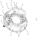
Figure 1 is a perspective view of a drum brake assembly according to a first embodiment; -
Figure 2 is a perspective view of the drum brake assembly ofFigure 1 with the brake drum removed to improve clarity; -
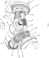
Figure 3 is a detailed view of the drum brake assembly ofFigures 1 and2 with further components removed to improve clarity; -
Figure 4 is an exploded view of the manual adjuster assembly, cam shaft and tappets of the drum brake assembly ofFigures 1-3 ; -
Figure 5 is a perspective view of a drum brake assembly according to a second embodiment; -
Figure 6 is a detailed view of the drum brake assembly ofFigure 5 with further components removed to improve clarity; and -
Figure 7 is a an exploded view of the manual adjuster assembly, cam shaft and tappets of the drum brake assembly ofFigures 5 and6 . -
Figures 1 and2 show adrum brake assembly 10 for a heavy commercial vehicle according to a first embodiment. Thedrum brake 10 includes acylindrical brake drum 12 and first 14 and second 16 brake shoe assemblies that are moveable into engagement with thebrake drum 12 by acam shaft 18. Thecam shaft 18 can be actuated pneumatically or hydraulically. - The
brake drum 12 is rotatable about an axis X. Thebrake drum 12 has an inner peripheral surface. Thebrake shoe assemblies internal cavity 22 of thebrake drum 12, adjacent to the inner peripheral surface (not shown). Thebrake shoe assemblies brake linings 24 of friction material. Thebrake linings 24 are attached to abacking plate 26 of eachassembly brake shoe assembly friction material 24. In alternative embodiments, each brake shoe assembly has a single portion of friction material, or three or more portions of friction material. - The inner peripheral surface of the
brake drum 12 forms a braking surface. When thedrum brake 10 is applied during a braking event, thebrake linings 24 are moved into contact with the braking surface following actuation of thebrake shoe assemblies cam shaft 18. - As shown more clearly in
Figures 3 and4 , thedrum brake assembly 10 is a Z cam drum brake assembly. A pair ofrods first end 18a of thecam shaft 18 such that angular displacement or rotation of thecam shaft 18 results in axial movement of eachrod - Axial movement of the
rods cam shaft 18 results in substantially corresponding movement of respective first andsecond tappet assemblies second tappet assemblies cam shaft 18 to the first and secondbrake shoe assemblies - Each
tappet assembly tappet sleeve portion body tappet sleeves slots 35 around a periphery of thesleeve slots 35 are arranged helically, at an angle to a longitudinal axis Y of thetappet body 36a. In this embodiment, theslots 35 extend fully though the depth of thesleeve body - A
force transfer component tappet body tappet body drum brake 10 eachforce transfer component brake shoe assembly flat surfaces force transfer component force transfer components plates 45 on eachbrake shoe assembly flat surfaces plates 45. Acover force transfer component - The
drum brake assembly 10 has awear adjuster mechanism 40 for adjusting the first andsecond tappet assemblies brake shoes brake drum 12. Thewear adjuster mechanism 40 acts to adjust the length of each of the first andsecond tappet assemblies tappet assembly friction material 24 and the braking surface occurs. - The
wear adjuster mechanism 40 has ahelical gear 42 that engages theoblique slots 35 of thefirst tappet sleeve 34a of thefirst tappet assembly 30a in order to rotate thetappet 32a with respect to thecover 38a and so extend the overall length of thetappet assembly 30a. Rotation of theforce transfer components plates 45. - Axial movement of the
first tappet assembly 30a upon application of thedrum brake 10 causes rotation of ashaft 41 of thewear adjuster mechanism 40 due to the engagement of thehelical gear 42 with theslots 35 of thefirst tappet sleeve 34a. Once rotation of theshaft 41 reaches a certain point, resulting axial movement of thehelical gear 42 in relation to theshaft 41, and the engagement of thehelical gear 42 with theslots 35 of thefirst tappet sleeve 34a, cause rotation of thetappet 32a with respect to thecover 38a. Thehelical gear 42 rotates upon application of thedrum brake 10. Thefirst tappet sleeve 34a does not rotate with thehelical gear 42. When thebrake 10 is released, a form on theshaft 41 prevents rotation. Thetappet sleeve 34a is thus forced to rotate with respect to thehelical gear 42 upon activation of a shoe-return spring. That is, thetappet 32a rotates within theforce transfer component 38a - rotation of which is prevented by theplates 45. - As in known adjuster mechanisms for Z cam brakes, the
wear adjuster mechanism 40 has across shaft 44 for transmitting rotational force from thetappet sleeve 34a of thefirst tappet assembly 30a to thetappet sleeve 34b of thesecond tappet assembly 30b. Thecross shaft 44 of this embodiment extends between the first andsecond tappet sleeves first end 18a of thecam shaft 18. Thecross shaft 44 has at each end ahelical gear 46 for engagement withslots 35 of therespective tappet sleeves wear adjuster mechanism 40 is thus used to adjust bothtappet assemblies - A
sensor 48 is provided for detecting motion of thecross shaft 44. As thecross shaft 44 is rotated as thewear adjuster mechanism 40 is activated to address wear, the amount of wear of thefriction material 24 and the braking surface can be calculated from the amount of rotation from thecross shaft 44 that has taken place. Detection of the rotation of thecross shaft 44 by the measurement of e.g. rotation of the cross shaft can thus be used to provide an indication of the amount of wear that has taken place. - Advantageously, detection of the amount of wear using the
sensor 48 allows monitoring to take place, so that maintenance of the drum brake assembly can be planned and the brake shoes can be replaced appropriately on a pre-determined schedule. The full usable life of thebrake shoes - In this embodiment, the
sensor 48 is for detecting rotation of thecross shaft 44 about a longitudinal axis Z. As thecross shaft 44 rotates in direct proportion to the amount by which the length of thefirst tappet 34a (and thus thesecond tappet 34b) is adjusted, by detecting the distance by which thecross shaft 44 has been rotated, the amount of wear can be calculated. Using rotation of thecross shaft 44 allows accurate calculation of wear, so that a replacement of thebrake shoes - In this embodiment, rotation of the
cross shaft 44 is continuously detected. An up-to-date indication of the state of wear can therefore be provided. - In alternative embodiments, rotation of the cross shaft is detected at intervals.
- In this embodiment, the
sensor 48 is mounted on thecam shaft 18. In this embodiment, thesensor 48 is mounted at thefirst end 18a of thecam shaft 18. In this embodiment, thesensor 48 is mounted to anend face 18b of thecam shaft 18. - Location of the
sensor 48 at thefirst end 18a of thecam shaft 18 allows thesensor 48 to be in a suitable and convenient location for the detection of rotation of thecross shaft 44, as thecross shaft 44 of this embodiment extends transverse to thefirst end 18a of thecam shaft 18. Advantageously, a compact arrangement is provided. - In alternative embodiments, the
sensor 48 is mounted elsewhere on thecam shaft 18, for example, on a circumferential surface of thecam shaft 18. In alternative embodiments, thesensor 48 is mounted to ahousing 50 of thedrum brake assembly 10. In alternative embodiments, thesensor 48 is mounted to acover plate 52 of thehousing 50. Such an arrangement provides a compact assembly without the need for additional components, and allows the sensor to be suitably located for the detection of rotation of thecross shaft 44. - In the embodiment shown in
Figures 2-4 , where thesensor 48 is mounted to thecam shaft 18, thesensor 48 is configured to detect angular displacement of thecam shaft 18 about a longitudinal axis T of thecam shaft 18. Detection of angular displacement of the cam shaft during a braking operation provides an indication of the stroke of thecam shaft 18 for each application of thedrum brake 10. When the stroke is known, running clearance can be determined, as the running clearance is known to be the distance travelled by thefriction material 24 before thefriction material 24 comes into contact with the braking surface. Monitoring of the running clearance over time will show if the brake wear adjuster mechanism is working correctly/optimally or if it is beginning to degrade. Service or maintenance can be planned if the running clearance is over a predetermined maximum distance, such that the brake is inefficient or under-performing, or if running clearance is below a predetermined minimum distance, and the brake is dragging. - As the stroke of the
cam shaft 18 will be affected by theadjuster mechanism 40 adjusting the length of each of the first andsecond tappets - Mounting the
sensor 48 on thecam shaft 18 allows the same sensor to be used to detect rotation of thecross shaft 44 and angular displacement of thecam shaft 18, allowing a minimal number of components and advantageously providing a compact arrangement. - In alternative embodiments, separate sensors, i.e. two or more sensors, are used to detect rotation of the
cross shaft 44 and angular displacement of thecam shaft 18. - The
drum brake assembly 10 has arotation indicator 54 for indicating rotation of thecross shaft 44 of thesensor 48 i.e. to allow thesensor 48 to detect rotation of thecross shaft 44. Therotation indicator 54 has afirst portion 56 and asecond portion 58. Thefirst portion 56 is moved by, or with, thecross shaft 44, i.e. in this embodiment, thefirst portion 56 rotates with thecross shaft 44 about the axis Z. - The
second portion 58 is engaged with thefirst portion 56 in such a way that movement of the first portion 56 - in this embodiment, rotation of thefirst portion 56 with the cross shaft 44 - causes proportional movement of thesecond portion 58. Thesensor 48 is arranged to detect the movement of thesecond portion 58, and so detect rotation of thefirst portion 56, so as to calculate rotation of thecross shaft 44. - In this embodiment, the first portion is a threaded
portion 56 of thecross shaft 44. The threadedportion 56 provides a simple and effective means of moving the second portion proportionally to rotation of thecross shaft 44. In this embodiment, the first portion is an externally threadedsleeve 56. Thesleeve 56 is splined to thecross shaft 44, so that thesleeve 56 rotates with thecross shaft 44. - In an alternative embodiment, the threaded portion is integral to the cross shaft, e.g. the threaded portion is machined with the cross shaft.
- The second portion is in this embodiment in the form of a
gear 58 that engages the threadedsleeve 56 in a worm drive arrangement, i.e. thegear 58 has a longitudinal axis R transverse to the longitudinal axis Z of thecross shaft 44. As thecross shaft 44 is rotated with the remainder of theadjuster mechanism 40, the threadedsleeve 56 causes thegear 58 to rotate about its axis R. Thesensor 48 detects rotation of thegear 58 and so can measure rotation of thecross shaft 44, so that the amount of adjustment for wear carried out by theadjuster mechanism 40 is known, and the amount of wear can be calculated. - In this embodiment, the
gear 58 is mounted on thecam shaft 18. In this embodiment, thegear 58 is mounted on thefirst end 18a of thecam shaft 18, at theend surface 18b. In this embodiment, thegear 58 is rotatably mounted to a projection of thesensor 48. Mounting of thegear 58 at thesensor 48, and at thefirst end 18a of thecam shaft 18, allows a compact arrangement without the need for multiple further components. - In alternative embodiments, the
gear 58 is mounted in some other suitable location. In one embodiment, thegear 58 is mounted to thehousing 50. In one embodiment, thegear 58 is mounted to thecover plate 52. - With reference now to
Figures 5 ,6 and7 , a further embodiment is described. Only components that differ from the embodiment ofFigures 2 to 4 will be described in detail. Like components are given the same reference number, with an additional prefix "1". - As shown in
Figures 5 ,6 and7 , in this embodiment, therotation indicator 154 differs from that of the previous embodiment. In this embodiment, the first portion comprises a threadedportion 156. In this embodiment, the threadedportion 156 is integral to thecross shaft 144, i.e. a portion of thecross shaft 144 defines anexternal thread 156. In alternative embodiments, the threaded portion is provided on a sleeve as described in relation to the previous embodiment. - In this embodiment, the
second portion 158 includes two components: acollar 160 and anarm 162. The collar is mounted on thecross shaft 144. Thecollar 160 defines aninternal thread 164 which engages the threadedportion 156. Thecollar 160 is thus rotatable in relation to thecross shaft 144. The collar has an outwardradial projection 166. Thearm 162 engages theradial projection 166. In this embodiment, thearm 162 defines aslot 168 through which theprojection 166 extends, providing engagement of the arm with theradial projection 166 and so with thecollar 160. In this embodiment, theslot 168 is a closed slot. - In alternative embodiments, the arm has some other formation for engagement with the projection, or with the collar. For example, in one embodiment, the arm defines an open ended slot so that the arm forms a fork.
- The engagement of the
projection 166 with thearm 162 causes axial movement of thecollar 160 along thecross shaft 144 when thecross shaft 144 is rotated. Thearm 162 is pivotably secured at afirst end 170. Axial movement of thecollar 160 upon rotation of thecross shaft 144 results in pivoting of thearm 162 about thefirst end 170. Thesensor 148 detects pivoting of thearm 162 and so detects rotation of thecross shaft 144. - In this embodiment, the
arm 162 is mounted to thefirst end 118a of thecam shaft 118. In this embodiment, thearm 162 is mounted to theend face 118b. In this embodiment, where the sensor is mounted on a cam shaft, thearm 162 is mounted at itsfirst end 170 to thesensor 148. - In alternative embodiments, the
arm 162 is mounted elsewhere, for example to the housing, or to the cover plate. - The
sensor 148 of the above embodiments is anencoder cross shaft 144. Such asensor cam shaft gear 58 orarm 162, so that a single sensor can be used for multiple functions. - In an alternative embodiment, the sensor is of some other type. In an alternative embodiment, the sensor is a potentiometer. In alternative embodiments, this sensor is some other type of suitable sensor.
- Monitoring of wear of the
brake shoes control system control system sensor cross shaft - The
control system indicator brake shoes indicator brake shoes friction material - As well as continuous monitoring of wear, the above arrangements advantageously allow the direction of rotation of the cross-shaft to be monitored.
Claims (15)
- A drum brake assembly for a heavy commercial vehicle, the drum brake assembly comprising:a brake drum;first and second brake shoes to be moved towards a braking surface of the brake drum during a braking operation;a cam shaft for transmitting braking force from an actuator to apply the brake;a first tappet and a second tappet for transmitting braking force from the cam shaft to the first and second brake shoes;a wear adjuster mechanism for adjusting the first and second tappets to address wear of the brake shoes and the braking surface of the brake drum, the wear adjuster mechanism comprising a cross shaft for transmitting rotational force from the first tappet to the second tappet; anda sensor for detecting rotation of the cross shaft about a longitudinal axis of the cross shaft in order to monitor wear of the brake shoes and the braking surface of the brake drum.
- A drum brake assembly according to claim 1, wherein the sensor is configured to continuously detect rotation of the cross shaft, such that wear of the brake shoes and the braking surface is continuously monitored.
- The drum brake assembly according to claim 2, wherein the sensor is mounted on the cam shaft, preferably wherein the sensor is configured to detect angular displacement of the cam shaft about the longitudinal axis of the cam shaft.
- The drum brake assembly according to claim 2 or claim 3, further comprising a rotation indicator for indicating rotation of the cross shaft to the sensor, wherein the rotation indicator includes a first portion configured for movement with the cross shaft, and a second portion engaged with the first portion such that movement of the first portion causes proportional movement of the second portion, wherein the sensor is configured to detect movement of the second portion.
- The drum brake assembly according to claim 4, wherein the first portion comprises a threaded portion of the cross shaft, preferably wherein the threaded portion is integral to the cross shaft, or wherein the threaded portion comprises an externally threaded sleeve mounted to the cross shaft for rotation with the cross shaft.
- The drum brake assembly according to claim 5, wherein the second portion comprises a gear with teeth corresponding to the thread of the first portion, such that rotation of the threaded portion with the cross shaft causes rotation of the gear.
- The drum brake assembly according to claim 6, wherein the gear is mounted on the cam shaft; preferably wherein, when the sensor is mounted on the cam shaft, the gear is mounted on the cam shaft via the sensor.
- The drum brake assembly according to claim 5, wherein the second portion comprises a collar mounted on the cross shaft, and an arm, wherein the collar comprises an internal thread for engaging the threaded portion and a radial projection configured to engage the arm such that rotation of the cross shaft causes axial movement of the collar with respect to the cross shaft, and pivoting of the arm about a first end of the arm, and wherein the sensor is configured to detect pivoting of the arm.
- The drum brake assembly according to claim 8, wherein the first end of the arm is mounted on the cam shaft; preferably wherein, when the sensor is mounted on the cam shaft, the first end of the arm is mounted on the cam shaft via the sensor.
- The drum brake assembly according to claim 1 or claim 2, further comprising a housing, wherein the sensor is mounted to the housing.
- The drum brake assembly according to any preceding claim, wherein the sensor is an encoder, or wherein the sensor is a potentiometer.
- The drum brake assembly according to any preceding claim, further comprising a control system for monitoring wear of the brake shoes and the braking surface, wherein the control system is configured to calculate wear from cumulative motion of the cross shaft during multiple braking operations, preferably wherein the control system comprises an indicator for indicating the state of wear of the brake shoes and/or the braking surface.
- A method of monitoring wear of the brake shoes and the braking surface of the drum brake assembly of claim 12, the method comprising the steps of:detecting motion of the cross shaft via the sensor; andusing the control system to calculate wear from cumulative motion of the cross shaft;preferably further comprising the step of providing an indication to an operator of the state of wear of the brake shoes and/or the braking surface.
- A drum brake assembly for a heavy commercial vehicle, the drum brake assembly comprising:a brake drum;first and second brake shoes to be moved towards a braking surface of the brake drum during a braking operation;a cam shaft for transmitting braking force from an actuator to apply the brake;a first tappet and a second tappet for transmitting braking force from the cam shaft to the first and second brake shoes;a wear adjuster mechanism for adjusting the first and second tappets to address wear of the brake shoes and the braking surface of the brake drum; anda sensor configured to detect angular displacement of the cam shaft about the longitudinal axis of the cam shaft.
- The drum brake assembly according to claim 14, wherein the sensor is mounted on the cam shaft.
Priority Applications (3)
| Application Number | Priority Date | Filing Date | Title |
|---|---|---|---|
| EP21201299.1A EP4163510B1 (en) | 2021-10-06 | 2021-10-06 | A drum brake |
| US17/892,470 US12631234B2 (en) | 2021-10-06 | 2022-08-22 | Drum brake |
| BR102022020180-3A BR102022020180A2 (en) | 2021-10-06 | 2022-10-05 | DRUM BRAKE |
Applications Claiming Priority (1)
| Application Number | Priority Date | Filing Date | Title |
|---|---|---|---|
| EP21201299.1A EP4163510B1 (en) | 2021-10-06 | 2021-10-06 | A drum brake |
Publications (2)
| Publication Number | Publication Date |
|---|---|
| EP4163510A1 true EP4163510A1 (en) | 2023-04-12 |
| EP4163510B1 EP4163510B1 (en) | 2026-03-04 |
Family
ID=78085566
Family Applications (1)
| Application Number | Title | Priority Date | Filing Date |
|---|---|---|---|
| EP21201299.1A Active EP4163510B1 (en) | 2021-10-06 | 2021-10-06 | A drum brake |
Country Status (3)
| Country | Link |
|---|---|
| US (1) | US12631234B2 (en) |
| EP (1) | EP4163510B1 (en) |
| BR (1) | BR102022020180A2 (en) |
Cited By (1)
| Publication number | Priority date | Publication date | Assignee | Title |
|---|---|---|---|---|
| WO2026057445A1 (en) * | 2024-09-12 | 2026-03-19 | Kb Intellectual Property Gmbh & Co. Kg | Drum brake and method for adjusting multiple brake shoes of a drum brake mounted in a receiving space of a brake drum |
Citations (2)
| Publication number | Priority date | Publication date | Assignee | Title |
|---|---|---|---|---|
| KR20050098321A (en) * | 2004-04-06 | 2005-10-12 | 현대자동차주식회사 | Brake apparatus with sensor for detecting loosing of lining |
| US20200011390A1 (en) * | 2017-01-25 | 2020-01-09 | Volvo Truck Corporation | Brake lining wear sensor |
Family Cites Families (6)
| Publication number | Priority date | Publication date | Assignee | Title |
|---|---|---|---|---|
| US2674351A (en) * | 1949-07-29 | 1954-04-06 | Kalb Ray E De | Brake shoe adjusting means |
| DE4230911A1 (en) * | 1992-09-16 | 1994-03-17 | Bosch Gmbh Robert | Method for determining the application pressure of a braking device for vehicles |
| DE19613199C1 (en) * | 1996-04-02 | 1997-10-23 | Bpw Bergische Achsen Kg | Device for adjusting and adjusting the brake shoes of a drum brake |
| FR2783582B1 (en) * | 1998-09-23 | 2000-11-17 | Bosch Syst Freinage | DRUM BRAKE USING SELECTIVE INHIBITION AUTOMATIC GAME RETRACTION |
| US6680672B2 (en) * | 2001-02-08 | 2004-01-20 | Volvo Trucks North America, Inc. | Vehicle diagnostic system |
| CN212155571U (en) * | 2020-03-28 | 2020-12-15 | 浙江德财制动系统有限公司 | Clearance self-adjusting automobile brake |
-
2021
- 2021-10-06 EP EP21201299.1A patent/EP4163510B1/en active Active
-
2022
- 2022-08-22 US US17/892,470 patent/US12631234B2/en active Active
- 2022-10-05 BR BR102022020180-3A patent/BR102022020180A2/en unknown
Patent Citations (2)
| Publication number | Priority date | Publication date | Assignee | Title |
|---|---|---|---|---|
| KR20050098321A (en) * | 2004-04-06 | 2005-10-12 | 현대자동차주식회사 | Brake apparatus with sensor for detecting loosing of lining |
| US20200011390A1 (en) * | 2017-01-25 | 2020-01-09 | Volvo Truck Corporation | Brake lining wear sensor |
Cited By (1)
| Publication number | Priority date | Publication date | Assignee | Title |
|---|---|---|---|---|
| WO2026057445A1 (en) * | 2024-09-12 | 2026-03-19 | Kb Intellectual Property Gmbh & Co. Kg | Drum brake and method for adjusting multiple brake shoes of a drum brake mounted in a receiving space of a brake drum |
Also Published As
| Publication number | Publication date |
|---|---|
| US12631234B2 (en) | 2026-05-19 |
| US20230105818A1 (en) | 2023-04-06 |
| BR102022020180A2 (en) | 2023-04-11 |
| EP4163510B1 (en) | 2026-03-04 |
Similar Documents
| Publication | Publication Date | Title |
|---|---|---|
| EP0764244B1 (en) | Brake lining wear sensing system | |
| EP1852628B1 (en) | Disc brake wear adjuster | |
| US7114596B2 (en) | Brake shoe proximity sensor | |
| EP3032131B1 (en) | Brake assembly and method of control | |
| EP1762746B1 (en) | Brake monitoring and control system | |
| US5339069A (en) | Brake monitoring system | |
| EP3032130B1 (en) | Brake assembly | |
| EP1633992B1 (en) | A sensor system for monitoring at least the wear of lining material of disc brakes | |
| US20060266598A1 (en) | Control method for adjusting a disc brake | |
| US12188535B2 (en) | Systems and methods for monitoring a wear state of a disc brake | |
| JP2005133941A (en) | Disc brake control system and method | |
| JP2013174357A (en) | Braking unit | |
| JP7262992B2 (en) | Wear amount calculation device, abnormal wear determination device, and brake device | |
| EP4163510B1 (en) | A drum brake | |
| EP3574227B1 (en) | Brake lining wear sensor | |
| EP0789156B1 (en) | Brake condition monitoring means | |
| WO2025073973A1 (en) | Vehicle monitoring system and method | |
| GB2310015A (en) | Vehicle brake assemblies |
Legal Events
| Date | Code | Title | Description |
|---|---|---|---|
| PUAI | Public reference made under article 153(3) epc to a published international application that has entered the european phase |
Free format text: ORIGINAL CODE: 0009012 |
|
| STAA | Information on the status of an ep patent application or granted ep patent |
Free format text: STATUS: THE APPLICATION HAS BEEN PUBLISHED |
|
| AK | Designated contracting states |
Kind code of ref document: A1 Designated state(s): AL AT BE BG CH CY CZ DE DK EE ES FI FR GB GR HR HU IE IS IT LI LT LU LV MC MK MT NL NO PL PT RO RS SE SI SK SM TR |
|
| P01 | Opt-out of the competence of the unified patent court (upc) registered |
Effective date: 20230531 |
|
| STAA | Information on the status of an ep patent application or granted ep patent |
Free format text: STATUS: REQUEST FOR EXAMINATION WAS MADE |
|
| 17P | Request for examination filed |
Effective date: 20230929 |
|
| RBV | Designated contracting states (corrected) |
Designated state(s): AL AT BE BG CH CY CZ DE DK EE ES FI FR GB GR HR HU IE IS IT LI LT LU LV MC MK MT NL NO PL PT RO RS SE SI SK SM TR |
|
| GRAP | Despatch of communication of intention to grant a patent |
Free format text: ORIGINAL CODE: EPIDOSNIGR1 |
|
| STAA | Information on the status of an ep patent application or granted ep patent |
Free format text: STATUS: GRANT OF PATENT IS INTENDED |
|
| RIC1 | Information provided on ipc code assigned before grant |
Ipc: F16D 125/28 20120101ALN20250513BHEP Ipc: F16D 66/02 20060101ALI20250513BHEP Ipc: F16D 65/56 20060101ALI20250513BHEP Ipc: F16D 65/22 20060101ALI20250513BHEP Ipc: F16D 51/24 20060101AFI20250513BHEP |
|
| INTG | Intention to grant announced |
Effective date: 20250530 |
|
| GRAJ | Information related to disapproval of communication of intention to grant by the applicant or resumption of examination proceedings by the epo deleted |
Free format text: ORIGINAL CODE: EPIDOSDIGR1 |
|
| STAA | Information on the status of an ep patent application or granted ep patent |
Free format text: STATUS: REQUEST FOR EXAMINATION WAS MADE |
|
| GRAP | Despatch of communication of intention to grant a patent |
Free format text: ORIGINAL CODE: EPIDOSNIGR1 |
|
| STAA | Information on the status of an ep patent application or granted ep patent |
Free format text: STATUS: GRANT OF PATENT IS INTENDED |
|
| INTC | Intention to grant announced (deleted) | ||
| INTG | Intention to grant announced |
Effective date: 20251014 |
|
| RIC1 | Information provided on ipc code assigned before grant |
Ipc: F16D 51/24 20060101AFI20251006BHEP Ipc: F16D 65/22 20060101ALI20251006BHEP Ipc: F16D 65/56 20060101ALI20251006BHEP Ipc: F16D 66/02 20060101ALI20251006BHEP Ipc: F16D 125/28 20120101ALN20251006BHEP |
|
| GRAS | Grant fee paid |
Free format text: ORIGINAL CODE: EPIDOSNIGR3 |
|
| GRAA | (expected) grant |
Free format text: ORIGINAL CODE: 0009210 |
|
| STAA | Information on the status of an ep patent application or granted ep patent |
Free format text: STATUS: THE PATENT HAS BEEN GRANTED |
|
| AK | Designated contracting states |
Kind code of ref document: B1 Designated state(s): AL AT BE BG CH CY CZ DE DK EE ES FI FR GB GR HR HU IE IS IT LI LT LU LV MC MK MT NL NO PL PT RO RS SE SI SK SM TR |
|
| REG | Reference to a national code |
Ref country code: CH Ref legal event code: F10 Free format text: ST27 STATUS EVENT CODE: U-0-0-F10-F00 (AS PROVIDED BY THE NATIONAL OFFICE) Effective date: 20260304 Ref country code: GB Ref legal event code: FG4D |
|
| REG | Reference to a national code |
Ref country code: DE Ref legal event code: R096 Ref document number: 602021049110 Country of ref document: DE |
|
| REG | Reference to a national code |
Ref country code: IE Ref legal event code: FG4D |
|
| PG25 | Lapsed in a contracting state [announced via postgrant information from national office to epo] |
Ref country code: RS Free format text: LAPSE BECAUSE OF FAILURE TO SUBMIT A TRANSLATION OF THE DESCRIPTION OR TO PAY THE FEE WITHIN THE PRESCRIBED TIME-LIMIT Effective date: 20260604 |
|
| PG25 | Lapsed in a contracting state [announced via postgrant information from national office to epo] |
Ref country code: ES Free format text: LAPSE BECAUSE OF FAILURE TO SUBMIT A TRANSLATION OF THE DESCRIPTION OR TO PAY THE FEE WITHIN THE PRESCRIBED TIME-LIMIT Effective date: 20260304 |
|
| REG | Reference to a national code |
Ref country code: NL Ref legal event code: MP Effective date: 20260304 |
|
| PG25 | Lapsed in a contracting state [announced via postgrant information from national office to epo] |
Ref country code: PL Free format text: LAPSE BECAUSE OF FAILURE TO SUBMIT A TRANSLATION OF THE DESCRIPTION OR TO PAY THE FEE WITHIN THE PRESCRIBED TIME-LIMIT Effective date: 20260304 |
|
| PG25 | Lapsed in a contracting state [announced via postgrant information from national office to epo] |
Ref country code: GR Free format text: LAPSE BECAUSE OF FAILURE TO SUBMIT A TRANSLATION OF THE DESCRIPTION OR TO PAY THE FEE WITHIN THE PRESCRIBED TIME-LIMIT Effective date: 20260605 |
|
| REG | Reference to a national code |
Ref country code: LT Ref legal event code: MG9D |
|
| PG25 | Lapsed in a contracting state [announced via postgrant information from national office to epo] |
Ref country code: LT Free format text: LAPSE BECAUSE OF FAILURE TO SUBMIT A TRANSLATION OF THE DESCRIPTION OR TO PAY THE FEE WITHIN THE PRESCRIBED TIME-LIMIT Effective date: 20260304 |
|
| PG25 | Lapsed in a contracting state [announced via postgrant information from national office to epo] |
Ref country code: NO Free format text: LAPSE BECAUSE OF FAILURE TO SUBMIT A TRANSLATION OF THE DESCRIPTION OR TO PAY THE FEE WITHIN THE PRESCRIBED TIME-LIMIT Effective date: 20260604 |
|
| PG25 | Lapsed in a contracting state [announced via postgrant information from national office to epo] |
Ref country code: FI Free format text: LAPSE BECAUSE OF FAILURE TO SUBMIT A TRANSLATION OF THE DESCRIPTION OR TO PAY THE FEE WITHIN THE PRESCRIBED TIME-LIMIT Effective date: 20260304 |
|
| PG25 | Lapsed in a contracting state [announced via postgrant information from national office to epo] |
Ref country code: HR Free format text: LAPSE BECAUSE OF FAILURE TO SUBMIT A TRANSLATION OF THE DESCRIPTION OR TO PAY THE FEE WITHIN THE PRESCRIBED TIME-LIMIT Effective date: 20260304 |
|
| PG25 | Lapsed in a contracting state [announced via postgrant information from national office to epo] |
Ref country code: LV Free format text: LAPSE BECAUSE OF FAILURE TO SUBMIT A TRANSLATION OF THE DESCRIPTION OR TO PAY THE FEE WITHIN THE PRESCRIBED TIME-LIMIT Effective date: 20260304 |
|
| PG25 | Lapsed in a contracting state [announced via postgrant information from national office to epo] |
Ref country code: BG Free format text: LAPSE BECAUSE OF FAILURE TO SUBMIT A TRANSLATION OF THE DESCRIPTION OR TO PAY THE FEE WITHIN THE PRESCRIBED TIME-LIMIT Effective date: 20260304 |