EP4163482A1 - Gas turbine engine with acoustic liner - Google Patents
Gas turbine engine with acoustic liner Download PDFInfo
- Publication number
- EP4163482A1 EP4163482A1 EP22200083.8A EP22200083A EP4163482A1 EP 4163482 A1 EP4163482 A1 EP 4163482A1 EP 22200083 A EP22200083 A EP 22200083A EP 4163482 A1 EP4163482 A1 EP 4163482A1
- Authority
- EP
- European Patent Office
- Prior art keywords
- fan case
- aft
- acoustic liner
- case
- retaining ring
- Prior art date
- Legal status (The legal status is an assumption and is not a legal conclusion. Google has not performed a legal analysis and makes no representation as to the accuracy of the status listed.)
- Granted
Links
Images


Classifications
-
- F—MECHANICAL ENGINEERING; LIGHTING; HEATING; WEAPONS; BLASTING
- F02—COMBUSTION ENGINES; HOT-GAS OR COMBUSTION-PRODUCT ENGINE PLANTS
- F02C—GAS-TURBINE PLANTS; AIR INTAKES FOR JET-PROPULSION PLANTS; CONTROLLING FUEL SUPPLY IN AIR-BREATHING JET-PROPULSION PLANTS
- F02C7/00—Features, components parts, details or accessories, not provided for in, or of interest apart form groups F02C1/00 - F02C6/00; Air intakes for jet-propulsion plants
- F02C7/04—Air intakes for gas-turbine plants or jet-propulsion plants
- F02C7/045—Air intakes for gas-turbine plants or jet-propulsion plants having provisions for noise suppression
-
- F—MECHANICAL ENGINEERING; LIGHTING; HEATING; WEAPONS; BLASTING
- F01—MACHINES OR ENGINES IN GENERAL; ENGINE PLANTS IN GENERAL; STEAM ENGINES
- F01D—NON-POSITIVE DISPLACEMENT MACHINES OR ENGINES, e.g. STEAM TURBINES
- F01D25/00—Component parts, details, or accessories, not provided for in, or of interest apart from, other groups
- F01D25/24—Casings; Casing parts, e.g. diaphragms, casing fastenings
- F01D25/243—Flange connections; Bolting arrangements
-
- F—MECHANICAL ENGINEERING; LIGHTING; HEATING; WEAPONS; BLASTING
- F02—COMBUSTION ENGINES; HOT-GAS OR COMBUSTION-PRODUCT ENGINE PLANTS
- F02K—JET-PROPULSION PLANTS
- F02K3/00—Plants including a gas turbine driving a compressor or a ducted fan
- F02K3/02—Plants including a gas turbine driving a compressor or a ducted fan in which part of the working fluid by-passes the turbine and combustion chamber
- F02K3/04—Plants including a gas turbine driving a compressor or a ducted fan in which part of the working fluid by-passes the turbine and combustion chamber the plant including ducted fans, i.e. fans with high volume, low pressure outputs, for augmenting the jet thrust, e.g. of double-flow type
- F02K3/06—Plants including a gas turbine driving a compressor or a ducted fan in which part of the working fluid by-passes the turbine and combustion chamber the plant including ducted fans, i.e. fans with high volume, low pressure outputs, for augmenting the jet thrust, e.g. of double-flow type with front fan
-
- B—PERFORMING OPERATIONS; TRANSPORTING
- B64—AIRCRAFT; AVIATION; COSMONAUTICS
- B64D—EQUIPMENT FOR FITTING IN OR TO AIRCRAFT; FLIGHT SUITS; PARACHUTES; ARRANGEMENT OR MOUNTING OF POWER PLANTS OR PROPULSION TRANSMISSIONS IN AIRCRAFT
- B64D33/00—Arrangement in aircraft of power plant parts or auxiliaries not otherwise provided for
- B64D33/02—Arrangement in aircraft of power plant parts or auxiliaries not otherwise provided for of combustion air intakes
- B64D2033/0206—Arrangement in aircraft of power plant parts or auxiliaries not otherwise provided for of combustion air intakes comprising noise reduction means, e.g. acoustic liners
-
- B—PERFORMING OPERATIONS; TRANSPORTING
- B64—AIRCRAFT; AVIATION; COSMONAUTICS
- B64D—EQUIPMENT FOR FITTING IN OR TO AIRCRAFT; FLIGHT SUITS; PARACHUTES; ARRANGEMENT OR MOUNTING OF POWER PLANTS OR PROPULSION TRANSMISSIONS IN AIRCRAFT
- B64D33/00—Arrangement in aircraft of power plant parts or auxiliaries not otherwise provided for
- B64D33/02—Arrangement in aircraft of power plant parts or auxiliaries not otherwise provided for of combustion air intakes
-
- F—MECHANICAL ENGINEERING; LIGHTING; HEATING; WEAPONS; BLASTING
- F05—INDEXING SCHEMES RELATING TO ENGINES OR PUMPS IN VARIOUS SUBCLASSES OF CLASSES F01-F04
- F05D—INDEXING SCHEME FOR ASPECTS RELATING TO NON-POSITIVE-DISPLACEMENT MACHINES OR ENGINES, GAS-TURBINES OR JET-PROPULSION PLANTS
- F05D2260/00—Function
- F05D2260/02—Transport and handling during maintenance and repair
-
- F—MECHANICAL ENGINEERING; LIGHTING; HEATING; WEAPONS; BLASTING
- F05—INDEXING SCHEMES RELATING TO ENGINES OR PUMPS IN VARIOUS SUBCLASSES OF CLASSES F01-F04
- F05D—INDEXING SCHEME FOR ASPECTS RELATING TO NON-POSITIVE-DISPLACEMENT MACHINES OR ENGINES, GAS-TURBINES OR JET-PROPULSION PLANTS
- F05D2260/00—Function
- F05D2260/30—Retaining components in desired mutual position
-
- F—MECHANICAL ENGINEERING; LIGHTING; HEATING; WEAPONS; BLASTING
- F05—INDEXING SCHEMES RELATING TO ENGINES OR PUMPS IN VARIOUS SUBCLASSES OF CLASSES F01-F04
- F05D—INDEXING SCHEME FOR ASPECTS RELATING TO NON-POSITIVE-DISPLACEMENT MACHINES OR ENGINES, GAS-TURBINES OR JET-PROPULSION PLANTS
- F05D2260/00—Function
- F05D2260/96—Preventing, counteracting or reducing vibration or noise
-
- F—MECHANICAL ENGINEERING; LIGHTING; HEATING; WEAPONS; BLASTING
- F05—INDEXING SCHEMES RELATING TO ENGINES OR PUMPS IN VARIOUS SUBCLASSES OF CLASSES F01-F04
- F05D—INDEXING SCHEME FOR ASPECTS RELATING TO NON-POSITIVE-DISPLACEMENT MACHINES OR ENGINES, GAS-TURBINES OR JET-PROPULSION PLANTS
- F05D2300/00—Materials; Properties thereof
- F05D2300/60—Properties or characteristics given to material by treatment or manufacturing
- F05D2300/603—Composites; e.g. fibre-reinforced
-
- Y—GENERAL TAGGING OF NEW TECHNOLOGICAL DEVELOPMENTS; GENERAL TAGGING OF CROSS-SECTIONAL TECHNOLOGIES SPANNING OVER SEVERAL SECTIONS OF THE IPC; TECHNICAL SUBJECTS COVERED BY FORMER USPC CROSS-REFERENCE ART COLLECTIONS [XRACs] AND DIGESTS
- Y02—TECHNOLOGIES OR APPLICATIONS FOR MITIGATION OR ADAPTATION AGAINST CLIMATE CHANGE
- Y02T—CLIMATE CHANGE MITIGATION TECHNOLOGIES RELATED TO TRANSPORTATION
- Y02T50/00—Aeronautics or air transport
- Y02T50/60—Efficient propulsion technologies, e.g. for aircraft
Definitions
- the present disclosure pertains to gas turbine engines and more specifically to a gas turbine engine with an acoustic liner that extends between the inlet case and fan cases.
- the engine inlet case (or inlet cowl) and fan case may be a challenge to acoustically treat due to a structural segmentation of acoustic liners between inlet case and the fan case. Such structural segmentation of the acoustic liners may also result in flow path interface, introducing flow disturbances upstream of the fan.
- an assembly for a gas turbine engine including: a fan case, the fan case having a forward end, an aft end, and an inner surface extending from the forward end of the fan case to the aft end of the fan case; an acoustic liner having a forward end, an aft end, and an acoustic liner body that extends continuously from the forward end of the acoustic liner to the aft end of the acoustic liner; an inlet case located forward of the forward end of the fan case, the forward end of the acoustic liner being secured to the inlet case, and wherein the acoustic liner body is positioned against an inner surface of the inlet case and an inner surface of the fan case, and the aft end of the acoustic liner is secured to the fan case between the forward end and the aft end of the fan case.
- the inner surface of the fan case defines a forward portion and an aft portion, wherein the forward portion of the fan case extends toward the forward end of the fan case and is axially forward of a fan that is surrounded by the fan case, and the aft portion of the fan case extends toward the aft end of the fan case and is axially aligned with the fan; and a retaining ring is connected to the inner surface of the fan case in the forward portion of the fan case, wherein the aft end of the acoustic liner and the retaining ring engage each other to restrict motion of the aft end of the acoustic liner.
- the aft end of the acoustic liner has an end surface that defines a lead-in chamfer via a frustoconical shape having an aft taper; and the retaining ring has a forward end, and a retaining ring body that extends from the forward end of the retaining ring to an aft end of the retaining ring, wherein the forward end of the retaining ring has a retaining ring groove with a frustoconical shape that is configured to receive the aft end of the acoustic liner.
- a damper is bonded to the retaining ring groove and disposed between the retaining ring groove and the aft end of the acoustic liner.
- a forward gap is defined between the aft end of the acoustic liner and the damper; and a potting compound is disposed in the forward gap, to thereby fill the forward gap.
- the assembly includes: a rub strip is connected to the inner surface of the fan case, the rub strip including a forward end, and a rub strip body that extends to the aft end of the fan case; the retaining ring is axially adjacent to the forward end of the rub strip, wherein an aft gap is defined between the retaining ring and the forward end of the rub strip; and the potting compound is disposed in the aft gap, to thereby fill the aft gap.
- the retaining ring is bonded to the fan case; or the fan case and retaining ring are a unitary structure formed of a composite.
- spacer shims are disposed between the acoustic liner and the fan case to define a radial gap between the acoustic liner body and the fan case; and the spacer shims are axially discrete and axially spaced apart from each other along the acoustic liner.
- a gas turbine engine including: a fan; a fan case that surrounds the fan, the fan case having a forward end, an aft end, and an inner surface extending from the forward end of the fan case to the aft end of the fan case; an acoustic liner having a forward end, an aft end, and an acoustic liner body that extends continuously from the forward end of the acoustic liner to the aft end of the acoustic liner; an inlet case located forward of the forward end of the fan case, the forward end of the acoustic liner being secured to the inlet case, and wherein the acoustic liner body is positioned against an inner surface of the inlet case and an inner surface of the fan case, and the aft end of the acoustic liner is secured to the fan case between the forward end and the aft end of the fan case.
- the inner surface of the fan case defines a forward portion and an aft portion, wherein the forward portion of the fan case extends toward the forward end of the fan case and is axially forward of a fan that is surrounded by the fan case, and the aft portion of the fan case extends toward the aft end of the fan case and is axially aligned with the fan; and a retaining ring is connected to the inner surface of the fan case in the forward portion of the fan case, wherein the aft end of the acoustic liner and the retaining ring engage each other to restrict motion of the aft end of the acoustic liner.
- the aft end of the acoustic liner has an end surface that defines a lead-in chamfer via a frustoconical shape having an aft taper; and the retaining ring has a forward end, and a retaining ring body that extends from the forward end of the retaining ring to an aft end of the retaining ring, wherein the forward end of the retaining ring has a retaining ring groove with a frustoconical shape that is configured to receive the aft end of the acoustic liner.
- a damper is bonded to the retaining ring groove and disposed between the retaining ring groove and the aft end of the acoustic liner.
- a forward gap is defined between the aft end of the acoustic liner and the damper; and a potting compound is disposed in the forward gap, to thereby fill the forward gap.
- the engine includes a rub strip is connected to the inner surface of the fan case, the rub strip including a forward end, and a rub strip body that extends to the aft end of the fan case; the retaining ring is axially adjacent to the forward end of the rub strip, wherein an aft gap is defined between the retaining ring and the forward end of the rub strip; and the potting compound is disposed in the aft gap, to thereby fill the aft gap.
- the engine includes the retaining ring is bonded to the fan case; or the fan case and retaining ring are a unitary structure formed of a composite.
- spacer shims are disposed between the acoustic liner and the fan case to define a radial gap between the acoustic liner body and the fan case; and the spacer shims are axially discrete and axially spaced apart from each other along the acoustic liner.
- the aft end of the inlet case defines an aft flange, the aft flange has an aft guide aperture;
- the forward end of the fan case defines a forward flange, the forward flange has a forward guide aperture; and a guide pin extends through the aft guide aperture and the forward guide aperture and is configured to align the acoustic liner and the retaining ring, and restrict rotational and translational motion between the inlet case and the fan case, during assembly.
- a method is disclosed of assembling an inlet case and a fan case of a gas turbine engine, including: guiding the inlet case toward the fan case; and guiding an aft end of an acoustic liner that is connected to the inlet case until the aft end of the acoustic liner engages a retaining ring that is bonded to or formed as part of an inner surface of the fan case and is spaced apart from the forward end of the fan case.
- the method includes filling a gap formed between the aft end of the acoustic liner and the retaining ring with bonding compound.
- guiding the inlet case toward the fan case includes inserting a guide pin through an aft flange of the inlet case and a forward flange of the fan case and thereafter moving the inlet case toward the fan case.
- FIG. 1 schematically illustrates a gas turbine engine 20.
- the gas turbine engine 20 is disclosed herein as a two-spool turbofan that generally incorporates a fan section 22, a compressor section 24, a combustor section 26 and a turbine section 28.
- Alternative engines might include other systems or features.
- the fan section 22 drives air along a bypass flow path B in a bypass duct, while the compressor section 24 drives air along a core flow path C for compression and communication into the combustor section 26 then expansion through the turbine section 28.
- a nacelle 28 surrounds the fan section 22.
- a forward end of the nacelle 28 defines a nose 29 of the nacelle 28.
- the exemplary engine 20 generally includes a low speed spool 30 and a high speed spool 32 mounted for rotation about an engine central longitudinal axis A (engine radial axis R is also illustrated in FIG. 1 ) relative to an engine static structure 36 via several bearing systems 38. It should be understood that various bearing systems 38 at various locations may alternatively or additionally be provided, and the location of bearing systems 38 may be varied as appropriate to the application.
- the low speed spool 30 generally includes an inner shaft 40 that interconnects a fan 42, a low pressure compressor 44 and a low pressure turbine 46.
- the inner shaft 40 is connected to the fan 42 through a speed change mechanism, which in exemplary gas turbine engine 20 is illustrated as a geared architecture 48 to drive the fan 42 at a lower speed than the low speed spool 30.
- the high speed spool 32 includes an outer shaft 50 that interconnects a high pressure compressor 52 and high pressure turbine 54.
- a combustor 56 is arranged in exemplary gas turbine 20 between the high pressure compressor 52 and the high pressure turbine 54.
- An engine static structure 36 is arranged generally between the high pressure turbine 54 and the low pressure turbine 46.
- the engine static structure 36 further supports bearing systems 38 in the turbine section 28.
- the inner shaft 40 and the outer shaft 50 are concentric and rotate via bearing systems 38 about the engine central longitudinal axis A which is collinear with their longitudinal axes.
- each of the positions of the fan section 22, compressor section 24, combustor section 26, turbine section 28, and fan drive gear system 48 may be varied.
- gear system 48 may be located aft of combustor section 26 or even aft of turbine section 28, and fan section 22 may be positioned forward or aft of the location of gear system 48.
- the engine 20 in one example is a high bypass geared aircraft engine.
- the engine 20 bypass ratio is greater than about six, with an example embodiment being greater than about ten
- the geared architecture 48 is an epicyclic gear train, such as a planetary gear system or other gear system, with a gear reduction ratio of greater than about 2.3 and the low pressure turbine 46 has a pressure ratio that is greater than about five.
- the engine 20 bypass ratio is greater than about ten
- the fan diameter is significantly larger than that of the low pressure compressor 44
- the low pressure turbine 46 has a pressure ratio that is greater than about five.
- Low pressure turbine 46 pressure ratio is pressure measured prior to inlet of low pressure turbine 46 as related to the pressure at the outlet of the low pressure turbine 46 prior to an exhaust nozzle.
- the geared architecture 48 may be an epicycle gear train, such as a planetary gear system or other gear system, with a gear reduction ratio of greater than about 2.3:1. It should be understood, however, that the above parameters are only exemplary of one embodiment of a geared architecture engine and that the present disclosure is applicable to other gas turbine engines including direct drive turbofans.
- the fan section 22 of the engine 20 is designed for a particular flight condition--typically cruise at about 0.8Mach and about 35,000 feet (10,688 meters).
- 'TSFC' Thrust Specific Fuel Consumption
- Low fan pressure ratio is the pressure ratio across the fan blade alone, without a Fan Exit Guide Vane (“FEGV”) system.
- the low fan pressure ratio as disclosed herein according to one non-limiting embodiment is less than about 1.45.
- the "Low corrected fan tip speed” as disclosed herein according to one non-limiting embodiment is less than about 1150 ft/second (350.5 m/sec).
- an assembly 100 is provided for the gas turbine engine 20.
- the assembly 100 includes the fan case 110.
- the fan case 110 has a forward end 110A, an aft end 110B, and an inner surface 115 extending from the forward end 110A of the fan case 110 to the aft end 110B of the fan case 110.
- An acoustic liner 120 is shown.
- the acoustic liner 120 has a forward end 120A, an aft end 120B, and an acoustic liner body 125 that is elongated and extends continuously from the forward end 120A of the acoustic liner 120 to the aft end 120B of the acoustic liner 120.
- An inlet case 130 is also shown.
- the inlet case 130 is located forward of the forward end 110A of the fan case 110.
- the forward end 120A of the acoustic liner 120 is secured to the inlet case 130.
- the securing implements may be welds, fasteners, adhesives or other such securing implements.
- the acoustic liner body 125 is positioned against an inner surface 135 of the inlet case 130 and an inner surface 115 of the fan case 110.
- the aft end 120B of the acoustic liner 120 is secured to the fan case 110 between the forward end 110A of the fan case 110 and the aft end 110B of the fan case 110. As shown in the figure, the aft end 120B of the acoustic liner 120 is located so that it is spaced apart from the forward end of the fan case 110.
- the acoustic liner 120 continuously extends between the fan case 110 and the inlet case 130. With this configuration, disruptions in acoustic damping between the cases 110, 120 is reduced compared with segmented liners that terminate at a boundary 140 between the cases 110, 120.
- the continuous configuration of the acoustic liner 120 also reduces airflow disturbances that are created by edges of the segmented liners.
- the acoustic liner 120 is a cartridge liner having a face sheet 121 and a backing sheet 122 that are spaced apart from each other.
- An acoustic substrate 123 may be disposed between the face and backing sheets 121, 122.
- the inner surface 115 of the fan case 110 defines a forward portion 145A of the fan case 110 and an aft portion 145B of the fan case 110.
- the forward portion 145A of the fan case 110 is axially forward of the fan 42 that is surrounded by the fan case 110.
- the forward portion 145A of the fan case 110 extends toward the forward end 110A of the fan case 110.
- the aft portion 145B of the fan case 110 is axially aligned with the fan 42 and extends toward the aft end 110B of the fan case 110.
- the acoustic liner 120 is located in the forward portion 145A.
- a retaining ring 150 is connected to the inner surface 115 of the fan case 110.
- the retaining ring 150 is bonded to the inner surface 115 of the fan case 110.
- the fan case 110 and retaining ring 150 are a unitary structure formed of a composite.
- the retaining ring 150 is located in the forward portion 145A of the fan case 110, adjacent to the aft portion 145B of the fan case and spaced apart from the forward end 110A of the fan case 110.
- the aft end 120B of the acoustic liner 120 and the retaining ring 150 engage each other to restrict motion of the aft end 120B of the acoustic liner 120.
- the aft end of the acoustic liner 120 does not need to be secured via welds, fasteners, adhesives or the like.
- the retaining ring 150 could be located in the inlet case 130 rather than the fan case 110.
- the aft end 120B of the acoustic liner 120 could be fixed to the fan case 110 while the forward end 120A of the acoustic liner is secured via the retaining ring 150. That is, the opposite configuration of the illustrated embodiment is within the scope of the disclosure.
- the aft end 120B of the acoustic liner 120 has an end surface 160 that defines a lead-in chamfer via a frustoconical shape with an aft taper.
- the retaining ring 150 has a forward end 150A, and a retaining ring body 155 that extends from the forward end 150A of the retaining ring 150 to an aft end 150B of the retaining ring 150.
- the forward end 150A of the retaining ring 150 has a retaining ring groove 170 with a frustoconical shape that is configured to receive the aft end 120B of the acoustic liner 120.
- the retaining ring groove 170 has a shape that is complementary to the shape of the aft end 120B of the acoustic liner 120.
- the conical shape enables the retaining ring 150 to function as a guide to the acoustic liner 120, e.g., in situations where the alignment between the retaining ring 150 and the acoustic liner 120 may be slightly skewed during assembly.
- a damper 180 is bonded to the retaining ring groove 170.
- the damper 180 is disposed between the retaining ring groove 170 and the aft end 120B of the acoustic liner 120.
- the damper 180 may prevent damage or separation of the retaining ring 150 and the acoustic liner 120 that could result from vibrations during operation of the engine 20 ( FIG. 1 ).
- a forward gap 190A may be defined between the aft end 120B of the acoustic liner 120 and the damper 180.
- the forward gap 190A may be formed due to a length of the acoustic liner 120 being slightly undersized, end to end, though within design tolerances.
- a potting compound 200 may be utilized to fill the forward gap 190A, to provide for a smooth airflow over the forward gap 190A.
- a rub strip 210 is connected to the inner surface 115 of the fan case 110.
- the rub strip 210 has a forward end 210A and a rub strip body 215 that extends to the aft end of the fan case 110.
- the retaining ring 150 is axially adjacent to the forward end 210A of the rub strip 210. Due to positioning tolerances, this configuration may result in forming an aft gap 190B between the rub strip 210 and the retaining ring 150.
- the potting compound 200 may be utilized to fill the aft gap 190B, to provide for a smooth airflow over the forward gap 190A.
- spacer shims 220 may be disposed between the acoustic liner 120 and the inner surface 115 of the fan case 110. This configuration may define a radial gap 190C between the acoustic liner 120 and the inner surface 115 of the fan case 110.
- the spacer shims 220 are axially discrete and axially spaced apart from each other along the acoustic liner 120. The spacer shims 220 reduce a contact surface area between the acoustic liner 120 and the fan case 110.
- the spacer shims 220 may also provide for damping vibrations that could otherwise occur due to an out-of-roundness shape of the acoustic liner 120.
- the aft end 235 of the inlet case 130 defines an aft flange 230A.
- the aft flange 230A may have an aft guide aperture 240A.
- the forward end 110A of the fan case 110 defines a forward flange 230B.
- the forward flange 230B may have a forward guide aperture 240B.
- a guide pin 250 may extend through the aft guide aperture 240A and the forward guide aperture 240B. In the figure, the head of the guide pin 250 is against the inlet case 130 via the aft flange 230A and the body of the guide pin 250 extends along the fan case 110.
- the guide pin 250 could be directionally reversed so that the head of it is against the forward end 110A of the fan case 110 and the body of the guide pin 250 extends along the inlet case 130.
- a length of the guide pin 250 and the configuration of the outer nacelle flowpath of the inlet and fan case may direct the directional orientation of the guide pin 250.
- the guide pin 250 may be utilized to align the acoustic liner 120 and the retaining ring 150. This configuration may restrict rotational and translational motion between the inlet case 130 and the fan case 110 during assembly.
- a flowchart shows a method of assembling the inlet case 130 with the fan case 110.
- the method includes guiding the inlet case 130 toward the fan case 110.
- the method includes guiding the at aft end 120B of the acoustic liner 120 that is connected to the inlet case 130 until the acoustic liner aft end engages a retaining ring 150 that is bonded to or formed as part of the inner surface 115 of the fan case 110 and is spaced apart from the forward end 110A of the fan case 110.
- the method includes filling a gap 190A (referred to above as the forward gap 190A) formed between the aft end 120B of the acoustic liner 120 and the retaining ring 150 with bonding compound 200.
- guiding inlet case 130 toward the fan case includes inserting a guide pin 250 through an aft flange 240A of the inlet case 130 and a forward flange 240B of the fan case 110 and thereafter moving the inlet case 130 toward the fan case 110.
- This configuration may restrict rotational and translational motion between the inlet case 130 and the fan case 110 during assembly so that the acoustic liner 120 more readily engages the retaining ring 150.
- the embodiments provide an acoustic liner that extends between the inlet case and the fan case and thus provides an acoustic treatment continuously between the cases. Such treatment has the beneficial result of reducing fan noise and reducing flow path disruptions between the inlet case and the fan case that can cause aerodynamic loses.
- the embodiments also include a securing feature in the form of a retaining ring that enables locating and securing the aft end of the acoustic liner.
Landscapes
- Engineering & Computer Science (AREA)
- Chemical & Material Sciences (AREA)
- Combustion & Propulsion (AREA)
- Mechanical Engineering (AREA)
- General Engineering & Computer Science (AREA)
- Structures Of Non-Positive Displacement Pumps (AREA)
Abstract
Description
- The present disclosure pertains to gas turbine engines and more specifically to a gas turbine engine with an acoustic liner that extends between the inlet case and fan cases.
- The engine inlet case (or inlet cowl) and fan case may be a challenge to acoustically treat due to a structural segmentation of acoustic liners between inlet case and the fan case. Such structural segmentation of the acoustic liners may also result in flow path interface, introducing flow disturbances upstream of the fan.
- Disclosed is an assembly for a gas turbine engine, including: a fan case, the fan case having a forward end, an aft end, and an inner surface extending from the forward end of the fan case to the aft end of the fan case; an acoustic liner having a forward end, an aft end, and an acoustic liner body that extends continuously from the forward end of the acoustic liner to the aft end of the acoustic liner; an inlet case located forward of the forward end of the fan case, the forward end of the acoustic liner being secured to the inlet case, and wherein the acoustic liner body is positioned against an inner surface of the inlet case and an inner surface of the fan case, and the aft end of the acoustic liner is secured to the fan case between the forward end and the aft end of the fan case.
- In addition to the above disclosed features for the assembly, the inner surface of the fan case defines a forward portion and an aft portion, wherein the forward portion of the fan case extends toward the forward end of the fan case and is axially forward of a fan that is surrounded by the fan case, and the aft portion of the fan case extends toward the aft end of the fan case and is axially aligned with the fan; and a retaining ring is connected to the inner surface of the fan case in the forward portion of the fan case, wherein the aft end of the acoustic liner and the retaining ring engage each other to restrict motion of the aft end of the acoustic liner.
- In addition to one or more of the above disclosed features for the assembly, the aft end of the acoustic liner has an end surface that defines a lead-in chamfer via a frustoconical shape having an aft taper; and the retaining ring has a forward end, and a retaining ring body that extends from the forward end of the retaining ring to an aft end of the retaining ring, wherein the forward end of the retaining ring has a retaining ring groove with a frustoconical shape that is configured to receive the aft end of the acoustic liner.
- In addition to one or more of the above disclosed features for the assembly, a damper is bonded to the retaining ring groove and disposed between the retaining ring groove and the aft end of the acoustic liner.
- In addition to one or more of the above disclosed features for the assembly, a forward gap is defined between the aft end of the acoustic liner and the damper; and a potting compound is disposed in the forward gap, to thereby fill the forward gap.
- In addition to one or more of the above disclosed features for the assembly, the assembly includes: a rub strip is connected to the inner surface of the fan case, the rub strip including a forward end, and a rub strip body that extends to the aft end of the fan case; the retaining ring is axially adjacent to the forward end of the rub strip, wherein an aft gap is defined between the retaining ring and the forward end of the rub strip; and the potting compound is disposed in the aft gap, to thereby fill the aft gap.
- In addition to one or more of the above disclosed features for the assembly, the retaining ring is bonded to the fan case; or the fan case and retaining ring are a unitary structure formed of a composite.
- In addition to one or more of the above disclosed features for the assembly, spacer shims are disposed between the acoustic liner and the fan case to define a radial gap between the acoustic liner body and the fan case; and the spacer shims are axially discrete and axially spaced apart from each other along the acoustic liner.
- A gas turbine engine is disclosed, including: a fan; a fan case that surrounds the fan, the fan case having a forward end, an aft end, and an inner surface extending from the forward end of the fan case to the aft end of the fan case; an acoustic liner having a forward end, an aft end, and an acoustic liner body that extends continuously from the forward end of the acoustic liner to the aft end of the acoustic liner; an inlet case located forward of the forward end of the fan case, the forward end of the acoustic liner being secured to the inlet case, and wherein the acoustic liner body is positioned against an inner surface of the inlet case and an inner surface of the fan case, and the aft end of the acoustic liner is secured to the fan case between the forward end and the aft end of the fan case.
- In addition to the above disclosed features for the engine, the inner surface of the fan case defines a forward portion and an aft portion, wherein the forward portion of the fan case extends toward the forward end of the fan case and is axially forward of a fan that is surrounded by the fan case, and the aft portion of the fan case extends toward the aft end of the fan case and is axially aligned with the fan; and a retaining ring is connected to the inner surface of the fan case in the forward portion of the fan case, wherein the aft end of the acoustic liner and the retaining ring engage each other to restrict motion of the aft end of the acoustic liner.
- In addition to one or more of the above disclosed features for the engine, the aft end of the acoustic liner has an end surface that defines a lead-in chamfer via a frustoconical shape having an aft taper; and
the retaining ring has a forward end, and a retaining ring body that extends from the forward end of the retaining ring to an aft end of the retaining ring, wherein the forward end of the retaining ring has a retaining ring groove with a frustoconical shape that is configured to receive the aft end of the acoustic liner. - In addition to one or more of the above disclosed features for the engine, a damper is bonded to the retaining ring groove and disposed between the retaining ring groove and the aft end of the acoustic liner.
- In addition to one or more of the above disclosed features for the engine, a forward gap is defined between the aft end of the acoustic liner and the damper; and a potting compound is disposed in the forward gap, to thereby fill the forward gap.
- In addition to one or more of the above disclosed features for the engine, the engine includes a rub strip is connected to the inner surface of the fan case, the rub strip including a forward end, and a rub strip body that extends to the aft end of the fan case; the retaining ring is axially adjacent to the forward end of the rub strip, wherein an aft gap is defined between the retaining ring and the forward end of the rub strip; and the potting compound is disposed in the aft gap, to thereby fill the aft gap.
- In addition to one or more of the above disclosed features for the engine, the engine includes the retaining ring is bonded to the fan case; or the fan case and retaining ring are a unitary structure formed of a composite.
- In addition to one or more of the above disclosed features for the engine, spacer shims are disposed between the acoustic liner and the fan case to define a radial gap between the acoustic liner body and the fan case; and the spacer shims are axially discrete and axially spaced apart from each other along the acoustic liner.
- In addition to one or more of the above disclosed features for the engine, the aft end of the inlet case defines an aft flange, the aft flange has an aft guide aperture; the forward end of the fan case defines a forward flange, the forward flange has a forward guide aperture; and a guide pin extends through the aft guide aperture and the forward guide aperture and is configured to align the acoustic liner and the retaining ring, and restrict rotational and translational motion between the inlet case and the fan case, during assembly.
- A method is disclosed of assembling an inlet case and a fan case of a gas turbine engine, including: guiding the inlet case toward the fan case; and guiding an aft end of an acoustic liner that is connected to the inlet case until the aft end of the acoustic liner engages a retaining ring that is bonded to or formed as part of an inner surface of the fan case and is spaced apart from the forward end of the fan case.
- In addition to the above disclosed features for the method, the method includes filling a gap formed between the aft end of the acoustic liner and the retaining ring with bonding compound.
- In addition to one or more of the above disclosed features for the method, guiding the inlet case toward the fan case includes inserting a guide pin through an aft flange of the inlet case and a forward flange of the fan case and thereafter moving the inlet case toward the fan case.
- The following descriptions should not be considered limiting in any way. With reference to the accompanying drawings, like elements are numbered alike:
-
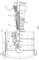
FIG. 1 is a partial cross-sectional view of a gas turbine engine, according to an embodiment; -
FIG. 2 is a detail of a portion ofFIG. 1 , and shows an acoustic liner extending between the inlet case and fan case; -
FIG. 3 shows additional aspects of the acoustic liner and the fan case; -
FIG. 4 is a detail of a portion ofFIG. 3 , and shows additional aspects of the acoustic liner, the fan case, and a retaining ring that is attached or bonded to the fan case and engages an aft end of the acoustic liner; -
FIG. 5 shows a guide pin that is configured to guide the inlet case toward the fan case while the aft end of the acoustic liner is guided toward the retaining ring, according to an embodiment; and -
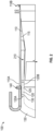
FIG. 6 shows a method of assembling an inlet case with a fan case, according to an embodiment. - A detailed description of one or more embodiments of the disclosed apparatus and method are presented herein by way of exemplification and not limitation with reference to the FIGS.
-
FIG. 1 schematically illustrates agas turbine engine 20. Thegas turbine engine 20 is disclosed herein as a two-spool turbofan that generally incorporates afan section 22, acompressor section 24, acombustor section 26 and aturbine section 28. Alternative engines might include other systems or features. Thefan section 22 drives air along a bypass flow path B in a bypass duct, while thecompressor section 24 drives air along a core flow path C for compression and communication into thecombustor section 26 then expansion through theturbine section 28. Anacelle 28 surrounds thefan section 22. A forward end of thenacelle 28 defines anose 29 of thenacelle 28. Although depicted as a two-spool turbofan gas turbine engine in the disclosed non-limiting embodiment, it should be understood that the concepts described herein are not limited to use with two-spool turbofans as the teachings may be applied to other types of turbine engines including three-spool architectures. - The
exemplary engine 20 generally includes alow speed spool 30 and ahigh speed spool 32 mounted for rotation about an engine central longitudinal axis A (engine radial axis R is also illustrated inFIG. 1 ) relative to an enginestatic structure 36 viaseveral bearing systems 38. It should be understood thatvarious bearing systems 38 at various locations may alternatively or additionally be provided, and the location ofbearing systems 38 may be varied as appropriate to the application. - The
low speed spool 30 generally includes aninner shaft 40 that interconnects afan 42, alow pressure compressor 44 and alow pressure turbine 46. Theinner shaft 40 is connected to thefan 42 through a speed change mechanism, which in exemplarygas turbine engine 20 is illustrated as a gearedarchitecture 48 to drive thefan 42 at a lower speed than thelow speed spool 30. Thehigh speed spool 32 includes anouter shaft 50 that interconnects ahigh pressure compressor 52 andhigh pressure turbine 54. Acombustor 56 is arranged inexemplary gas turbine 20 between thehigh pressure compressor 52 and thehigh pressure turbine 54. An enginestatic structure 36 is arranged generally between thehigh pressure turbine 54 and thelow pressure turbine 46. The enginestatic structure 36 further supports bearingsystems 38 in theturbine section 28. Theinner shaft 40 and theouter shaft 50 are concentric and rotate viabearing systems 38 about the engine central longitudinal axis A which is collinear with their longitudinal axes. - The core airflow is compressed by the
low pressure compressor 44 then thehigh pressure compressor 52, mixed and burned with fuel in thecombustor 56, then expanded over thehigh pressure turbine 54 andlow pressure turbine 46. Theturbines low speed spool 30 andhigh speed spool 32 in response to the expansion. It will be appreciated that each of the positions of thefan section 22,compressor section 24,combustor section 26,turbine section 28, and fandrive gear system 48 may be varied. For example,gear system 48 may be located aft ofcombustor section 26 or even aft ofturbine section 28, andfan section 22 may be positioned forward or aft of the location ofgear system 48. - The
engine 20 in one example is a high bypass geared aircraft engine. In a further example, theengine 20 bypass ratio is greater than about six, with an example embodiment being greater than about ten, the gearedarchitecture 48 is an epicyclic gear train, such as a planetary gear system or other gear system, with a gear reduction ratio of greater than about 2.3 and thelow pressure turbine 46 has a pressure ratio that is greater than about five. In one disclosed embodiment, theengine 20 bypass ratio is greater than about ten, the fan diameter is significantly larger than that of thelow pressure compressor 44, and thelow pressure turbine 46 has a pressure ratio that is greater than about five.Low pressure turbine 46 pressure ratio is pressure measured prior to inlet oflow pressure turbine 46 as related to the pressure at the outlet of thelow pressure turbine 46 prior to an exhaust nozzle. The gearedarchitecture 48 may be an epicycle gear train, such as a planetary gear system or other gear system, with a gear reduction ratio of greater than about 2.3:1. It should be understood, however, that the above parameters are only exemplary of one embodiment of a geared architecture engine and that the present disclosure is applicable to other gas turbine engines including direct drive turbofans. - A significant amount of thrust is provided by the bypass flow B due to the high bypass ratio. The
fan section 22 of theengine 20 is designed for a particular flight condition--typically cruise at about 0.8Mach and about 35,000 feet (10,688 meters). The flight condition of 0.8 Mach and 35,000 ft. (10,688 meters), with the engine at its best fuel consumption--also known as "bucket cruise Thrust Specific Fuel Consumption ('TSFC')"--is the industry standard parameter of lbm of fuel being burned divided by lbf of thrust the engine produces at that minimum point. "Low fan pressure ratio" is the pressure ratio across the fan blade alone, without a Fan Exit Guide Vane ("FEGV") system. The low fan pressure ratio as disclosed herein according to one non-limiting embodiment is less than about 1.45. "Low corrected fan tip speed" is the actual fan tip speed in ft/sec divided by an industry standard temperature correction of [(Tram °R)/(518.7 °R)]0,5 (where °R = K × 9/5). The "Low corrected fan tip speed" as disclosed herein according to one non-limiting embodiment is less than about 1150 ft/second (350.5 m/sec). - As shown in
FIG. 2 , anassembly 100 is provided for thegas turbine engine 20. Theassembly 100 includes thefan case 110. Thefan case 110 has aforward end 110A, anaft end 110B, and aninner surface 115 extending from theforward end 110A of thefan case 110 to theaft end 110B of thefan case 110. Anacoustic liner 120 is shown. Theacoustic liner 120 has aforward end 120A, anaft end 120B, and anacoustic liner body 125 that is elongated and extends continuously from theforward end 120A of theacoustic liner 120 to theaft end 120B of theacoustic liner 120. Aninlet case 130 is also shown. Theinlet case 130 is located forward of theforward end 110A of thefan case 110. Theforward end 120A of theacoustic liner 120 is secured to theinlet case 130. The securing implements may be welds, fasteners, adhesives or other such securing implements. Theacoustic liner body 125 is positioned against aninner surface 135 of theinlet case 130 and aninner surface 115 of thefan case 110. Theaft end 120B of theacoustic liner 120 is secured to thefan case 110 between theforward end 110A of thefan case 110 and theaft end 110B of thefan case 110. As shown in the figure, theaft end 120B of theacoustic liner 120 is located so that it is spaced apart from the forward end of thefan case 110. - As indicated, the
acoustic liner 120 continuously extends between thefan case 110 and theinlet case 130. With this configuration, disruptions in acoustic damping between thecases boundary 140 between thecases acoustic liner 120 also reduces airflow disturbances that are created by edges of the segmented liners. - Turning to
FIG. 3 , in one embodiment theacoustic liner 120 is a cartridge liner having aface sheet 121 and abacking sheet 122 that are spaced apart from each other. Anacoustic substrate 123 may be disposed between the face andbacking sheets - The
inner surface 115 of thefan case 110 defines aforward portion 145A of thefan case 110 and anaft portion 145B of thefan case 110. Theforward portion 145A of thefan case 110 is axially forward of thefan 42 that is surrounded by thefan case 110. Theforward portion 145A of thefan case 110 extends toward theforward end 110A of thefan case 110. Theaft portion 145B of thefan case 110 is axially aligned with thefan 42 and extends toward theaft end 110B of thefan case 110. Within thefan case 110, theacoustic liner 120 is located in theforward portion 145A. - A retaining
ring 150 is connected to theinner surface 115 of thefan case 110. In one embodiment, the retainingring 150 is bonded to theinner surface 115 of thefan case 110. In another embodiment, thefan case 110 and retainingring 150 are a unitary structure formed of a composite. The retainingring 150 is located in theforward portion 145A of thefan case 110, adjacent to theaft portion 145B of the fan case and spaced apart from theforward end 110A of thefan case 110. Theaft end 120B of theacoustic liner 120 and the retainingring 150 engage each other to restrict motion of theaft end 120B of theacoustic liner 120. With the use of the retainingring 150, the aft end of theacoustic liner 120 does not need to be secured via welds, fasteners, adhesives or the like. - It is to be appreciated that the retaining
ring 150 could be located in theinlet case 130 rather than thefan case 110. In such embodiment, theaft end 120B of theacoustic liner 120 could be fixed to thefan case 110 while theforward end 120A of the acoustic liner is secured via the retainingring 150. That is, the opposite configuration of the illustrated embodiment is within the scope of the disclosure. - Turning to
FIG. 4 , theaft end 120B of theacoustic liner 120 has anend surface 160 that defines a lead-in chamfer via a frustoconical shape with an aft taper. The retainingring 150 has aforward end 150A, and a retainingring body 155 that extends from theforward end 150A of the retainingring 150 to anaft end 150B of the retainingring 150. Theforward end 150A of the retainingring 150 has a retainingring groove 170 with a frustoconical shape that is configured to receive theaft end 120B of theacoustic liner 120. That is, the retainingring groove 170 has a shape that is complementary to the shape of theaft end 120B of theacoustic liner 120. The conical shape enables the retainingring 150 to function as a guide to theacoustic liner 120, e.g., in situations where the alignment between the retainingring 150 and theacoustic liner 120 may be slightly skewed during assembly. - A
damper 180 is bonded to the retainingring groove 170. Thedamper 180 is disposed between the retainingring groove 170 and theaft end 120B of theacoustic liner 120. Thedamper 180 may prevent damage or separation of the retainingring 150 and theacoustic liner 120 that could result from vibrations during operation of the engine 20 (FIG. 1 ). - A
forward gap 190A may be defined between theaft end 120B of theacoustic liner 120 and thedamper 180. Theforward gap 190A may be formed due to a length of theacoustic liner 120 being slightly undersized, end to end, though within design tolerances. Apotting compound 200 may be utilized to fill theforward gap 190A, to provide for a smooth airflow over theforward gap 190A. - A
rub strip 210 is connected to theinner surface 115 of thefan case 110. Therub strip 210 has aforward end 210A and arub strip body 215 that extends to the aft end of thefan case 110. The retainingring 150 is axially adjacent to theforward end 210A of therub strip 210. Due to positioning tolerances, this configuration may result in forming anaft gap 190B between therub strip 210 and the retainingring 150. Thepotting compound 200 may be utilized to fill theaft gap 190B, to provide for a smooth airflow over theforward gap 190A. - As shown in
FIGS. 3 and4 , spacer shims 220 may be disposed between theacoustic liner 120 and theinner surface 115 of thefan case 110. This configuration may define aradial gap 190C between theacoustic liner 120 and theinner surface 115 of thefan case 110. In one embodiment, the spacer shims 220 are axially discrete and axially spaced apart from each other along theacoustic liner 120. The spacer shims 220 reduce a contact surface area between theacoustic liner 120 and thefan case 110. This configuration reduces contact friction between theacoustic liner 120 and thefan case 110 while theinlet case 130 is being moved into place against thefan case 110 and theacoustic liner 120 slides against theinner surface 115 of the fan case. The spacer shims 220 may also provide for damping vibrations that could otherwise occur due to an out-of-roundness shape of theacoustic liner 120. - Turning to
FIG. 5 , theaft end 235 of theinlet case 130 defines anaft flange 230A. Theaft flange 230A may have anaft guide aperture 240A. Theforward end 110A of thefan case 110 defines aforward flange 230B. Theforward flange 230B may have aforward guide aperture 240B. Aguide pin 250 may extend through theaft guide aperture 240A and theforward guide aperture 240B. In the figure, the head of theguide pin 250 is against theinlet case 130 via theaft flange 230A and the body of theguide pin 250 extends along thefan case 110. However, theguide pin 250 could be directionally reversed so that the head of it is against theforward end 110A of thefan case 110 and the body of theguide pin 250 extends along theinlet case 130. In practice a length of theguide pin 250 and the configuration of the outer nacelle flowpath of the inlet and fan case may direct the directional orientation of theguide pin 250. During assembly of theinlet case 130 andfan case 110, theguide pin 250 may be utilized to align theacoustic liner 120 and the retainingring 150. This configuration may restrict rotational and translational motion between theinlet case 130 and thefan case 110 during assembly. - Turning to
FIG. 6 , a flowchart shows a method of assembling theinlet case 130 with thefan case 110. As shown inblock 610, the method includes guiding theinlet case 130 toward thefan case 110. As shown inblock 620 the method includes guiding the ataft end 120B of theacoustic liner 120 that is connected to theinlet case 130 until the acoustic liner aft end engages a retainingring 150 that is bonded to or formed as part of theinner surface 115 of thefan case 110 and is spaced apart from theforward end 110A of thefan case 110. As shown inblock 630, the method includes filling agap 190A (referred to above as theforward gap 190A) formed between theaft end 120B of theacoustic liner 120 and the retainingring 150 withbonding compound 200. According to an embodiment, guidinginlet case 130 toward the fan case (block 610) includes inserting aguide pin 250 through anaft flange 240A of theinlet case 130 and aforward flange 240B of thefan case 110 and thereafter moving theinlet case 130 toward thefan case 110. This configuration may restrict rotational and translational motion between theinlet case 130 and thefan case 110 during assembly so that theacoustic liner 120 more readily engages the retainingring 150. - The embodiments provide an acoustic liner that extends between the inlet case and the fan case and thus provides an acoustic treatment continuously between the cases. Such treatment has the beneficial result of reducing fan noise and reducing flow path disruptions between the inlet case and the fan case that can cause aerodynamic loses. The embodiments also include a securing feature in the form of a retaining ring that enables locating and securing the aft end of the acoustic liner.
- The terminology used herein is for the purpose of describing particular embodiments only and is not intended to be limiting of the present disclosure. As used herein, the singular forms "a", "an" and "the" are intended to include the plural forms as well, unless the context clearly indicates otherwise. It will be further understood that the terms "comprises" and/or "comprising," when used in this specification, specify the presence of stated features, integers, steps, operations, elements, and/or components, but do not preclude the presence or addition of one or more other features, integers, steps, operations, element components, and/or groups thereof.
- While the present disclosure has been described with reference to an exemplary embodiment or embodiments, it will be understood by those skilled in the art that various changes may be made and equivalents may be substituted for elements thereof without departing from the scope of the present disclosure. In addition, many modifications may be made to adapt a particular situation or material to the teachings of the present disclosure without departing from the essential scope thereof. Therefore, it is intended that the present disclosure not be limited to the particular embodiment disclosed as the best mode contemplated for carrying out this present disclosure, but that the present disclosure will include all embodiments falling within the scope of the claims.
Claims (13)
- An assembly (100) for a gas turbine engine (20), comprising:a fan case (110), the fan case (110) having a forward end (110A), an aft end (110B), and an inner surface (115) extending from the forward end (110A) of the fan case (110) to the aft end (110B) of the fan case (110);an acoustic liner (120) having a forward end (120A), an aft end (120B), and an acoustic liner body (125) that extends continuously from the forward end (120A)of the acoustic liner (120) to the aft end (120B) of the acoustic liner (120); andan inlet case (130) located forward of the forward end (110A) of the fan case (110), the forward end (120A) of the acoustic liner (120) being secured to the inlet case (130),wherein the acoustic liner body (125) is positioned against an inner surface (135) of the inlet case (130) and the inner surface (115) of the fan case (110), and the aft end (120B) of the acoustic liner (120) is secured to the fan case (110) between the forward end (110A) and the aft end (110B) of the fan case (110).
- The assembly (100) of claim 1, wherein:the inner surface (115) of the fan case (110) defines a forward portion (145A) and an aft portion (145B) of the fan case (110),wherein the forward portion (145A) of the fan case (110) extends toward the forward end (110A) of the fan case (110) and is configured to be axially forward of a fan (42) that is surrounded by the fan case (110), and the aft portion (145B) of the fan case (110) extends toward the aft end (110B) of the fan case (110) and is configured to be axially aligned with the fan (42); anda retaining ring (150) is connected to the inner surface (115) of the fan case (110) in the forward portion (145A) of the fan case (110),wherein the aft end (120B) of the acoustic liner (120) and the retaining ring (150) engage each other to restrict motion of the aft end (120B) of the acoustic liner (120).
- The assembly (100) of claim 2, wherein:the aft end (120B) of the acoustic liner (120) has an end surface (160) that defines a lead-in chamfer via a frustoconical shape having an aft taper; andthe retaining ring (150) has a forward end (150A), and a retaining ring body (155) that extends from the forward end (150A) of the retaining ring (150) to an aft end (150B) of the retaining ring (150), wherein the forward end (150A) of the retaining ring (150) has a retaining ring groove (170) with a frustoconical shape that is configured to receive the aft end (120B) of the acoustic liner (120).
- The assembly (100) of claim 3, wherein:
a damper (180) is bonded to the retaining ring groove (170) and disposed between the retaining ring groove (170) and the aft end (120B) of the acoustic liner (120). - The assembly (100) of claim 4, wherein:a forward gap (190A) is defined between the aft end (120B) of the acoustic liner (120) and the damper (180); anda potting compound (200) is disposed in the forward gap (190A), to thereby fill the forward gap (190A).
- The assembly (100) of claim 5, comprising:a rub strip (210) is connected to the inner surface (115) of the fan case (110), the rub strip (210) including a forward end (210A), and a rub strip body (215) that extends to the aft end (110B) of the fan case (110);the retaining ring (150) is axially adjacent to the forward end (210A) of the rub strip (210),wherein an aft gap (190B) is defined between the retaining ring (150) and the forward end (210A) of the rub strip; (210) andthe potting compound (200) is disposed in the aft gap (190B), to thereby fill the aft gap (190B).
- The assembly (100) of any of claims 2 to 6, wherein:the retaining ring (150) is bonded to the fan case (110); orthe fan case (110) and retaining ring (150) are a unitary structure formed of a composite.
- The assembly (100) of any preceding claim, wherein:spacer shims (220) are disposed between the acoustic liner (120) and the fan case (110) to define a radial gap (190C) between the acoustic liner body (125) and the fan case (110); andthe spacer shims (220) are axially discrete and axially spaced apart from each other along the acoustic liner (120).
- A gas turbine engine (20), comprising a fan (42) and the assembly (100) of any preceding claim, wherein the fan case (110) surrounds the fan (42).
- The engine (20) of claim 9, wherein:an aft end (235) of the inlet case (130) defines an aft flange (230A), the aft flange (230A) has an aft guide aperture (240A);the forward end (110A) of the fan case (110) defines a forward flange (230B), the forward flange (230B) has a forward guide aperture (240B); anda guide pin (250) extends through the aft guide aperture (240A) and the forward guide aperture and (240B) is configured to align the acoustic liner (120) and a or the retaining ring (150) connected to the inner surface (115) of the fan case (110) in the forward portion (145A) of the fan case (110), and restrict rotational and translational motion between the inlet case (130) and the fan case (110), during assembly.
- A method of assembling an inlet case (130) and a fan case (110) of a gas turbine engine (20), comprising:guiding the inlet case (130) toward the fan case (110); andguiding an aft end (120B) of an acoustic liner (120) that is connected to the inlet case (130) until the aft end (120B) of the acoustic liner (120) engages a retaining ring (150) that is bonded to or formed as part of an inner surface (115) of the fan case (110) and is spaced apart from a forward end (110A) of the fan case (110).
- The method of claim 11, comprising:
filling a gap (190A) formed between the aft end (120B) of the acoustic liner (120) and the retaining ring (150) with a bonding compound (200). - The method of claim 11 or 12, wherein:
guiding the inlet case (130) toward the fan case (110) includes inserting a guide pin (250) through an aft flange (240A) of the inlet case (130) and a forward flange (240B) of the fan case (110) and thereafter moving the inlet case (130) toward the fan case (110).
Applications Claiming Priority (1)
| Application Number | Priority Date | Filing Date | Title |
|---|---|---|---|
| US17/495,461 US12188409B2 (en) | 2021-10-06 | 2021-10-06 | Gas turbine engine with acoustic liner |
Publications (2)
| Publication Number | Publication Date |
|---|---|
| EP4163482A1 true EP4163482A1 (en) | 2023-04-12 |
| EP4163482B1 EP4163482B1 (en) | 2025-11-26 |
Family
ID=83688721
Family Applications (1)
| Application Number | Title | Priority Date | Filing Date |
|---|---|---|---|
| EP22200083.8A Active EP4163482B1 (en) | 2021-10-06 | 2022-10-06 | Gas turbine engine with acoustic liner |
Country Status (2)
| Country | Link |
|---|---|
| US (1) | US12188409B2 (en) |
| EP (1) | EP4163482B1 (en) |
Cited By (1)
| Publication number | Priority date | Publication date | Assignee | Title |
|---|---|---|---|---|
| EP4707544A1 (en) * | 2024-09-06 | 2026-03-11 | RTX Corporation | Compliant dampening wedge mount for a fan liner |
Families Citing this family (2)
| Publication number | Priority date | Publication date | Assignee | Title |
|---|---|---|---|---|
| FR3117170B1 (en) * | 2020-12-07 | 2022-11-04 | Safran Nacelles | PROPULSION ASSEMBLY FOR AN AIRCRAFT AND ITS ASSEMBLY METHOD |
| WO2025188391A2 (en) * | 2023-12-20 | 2025-09-12 | Whisper Aero Inc. | Cartridge for inlet seal and liner |
Citations (5)
| Publication number | Priority date | Publication date | Assignee | Title |
|---|---|---|---|---|
| US20100084507A1 (en) * | 2006-10-02 | 2010-04-08 | Aircelle | Removable air intake structure for turbojet engine nacelle |
| US20100232932A1 (en) * | 2006-03-24 | 2010-09-16 | Guy Bernard Vauchel | Air inlet shroud structure |
| US20130048414A1 (en) * | 2011-08-22 | 2013-02-28 | Snecma | Soundproofing panel for turbomachine and turbomachine comprising such a panel |
| WO2014197053A2 (en) * | 2013-03-13 | 2014-12-11 | United Technologies Corporation | Thermally conforming acoustic liner cartridge for a gas turbine engine |
| US20150023780A1 (en) * | 2013-07-16 | 2015-01-22 | United Technologies Corporation | Liner attaching scheme |
Family Cites Families (9)
| Publication number | Priority date | Publication date | Assignee | Title |
|---|---|---|---|---|
| US4293053A (en) | 1979-12-18 | 1981-10-06 | United Technologies Corporation | Sound absorbing structure |
| FR2840647B1 (en) * | 2002-06-05 | 2004-10-29 | Airbus France | DEVICE FOR CONNECTING TWO TUBULAR PIECES OF AIRCRAFT TURBOREACTOR |
| US8028802B2 (en) | 2008-06-30 | 2011-10-04 | General Electric Company | Method and system for damped acoustic panels |
| US9617009B2 (en) * | 2013-02-22 | 2017-04-11 | United Technologies Corporation | ATR full ring sliding nacelle |
| GB201405496D0 (en) * | 2014-03-27 | 2014-05-14 | Rolls Royce Plc | Linear assembly |
| GB201406277D0 (en) * | 2014-04-08 | 2014-05-21 | Rolls Royce Deutschland | A gas turbine inlet |
| FR3086785B1 (en) | 2018-09-28 | 2022-01-21 | Airbus Operations Sas | ASSEMBLY COMPRISING TWO JUXTAPOSED ACOUSTIC PANELS IN WHICH THE PANELS HAVE A RESISTIVE FACE WHICH EXTENDS TO AN END WALL |
| GB201903716D0 (en) * | 2019-03-19 | 2019-05-01 | Rolls Royce Plc | Acoustic liner panel and containment for a gas turbine engine |
| BR102022003769A2 (en) * | 2021-05-04 | 2022-11-16 | The Boeing Company | NACELE ENTRY STRUCTURE OF AN ENGINE ASSEMBLY |
-
2021
- 2021-10-06 US US17/495,461 patent/US12188409B2/en active Active
-
2022
- 2022-10-06 EP EP22200083.8A patent/EP4163482B1/en active Active
Patent Citations (5)
| Publication number | Priority date | Publication date | Assignee | Title |
|---|---|---|---|---|
| US20100232932A1 (en) * | 2006-03-24 | 2010-09-16 | Guy Bernard Vauchel | Air inlet shroud structure |
| US20100084507A1 (en) * | 2006-10-02 | 2010-04-08 | Aircelle | Removable air intake structure for turbojet engine nacelle |
| US20130048414A1 (en) * | 2011-08-22 | 2013-02-28 | Snecma | Soundproofing panel for turbomachine and turbomachine comprising such a panel |
| WO2014197053A2 (en) * | 2013-03-13 | 2014-12-11 | United Technologies Corporation | Thermally conforming acoustic liner cartridge for a gas turbine engine |
| US20150023780A1 (en) * | 2013-07-16 | 2015-01-22 | United Technologies Corporation | Liner attaching scheme |
Cited By (1)
| Publication number | Priority date | Publication date | Assignee | Title |
|---|---|---|---|---|
| EP4707544A1 (en) * | 2024-09-06 | 2026-03-11 | RTX Corporation | Compliant dampening wedge mount for a fan liner |
Also Published As
| Publication number | Publication date |
|---|---|
| EP4163482B1 (en) | 2025-11-26 |
| US12188409B2 (en) | 2025-01-07 |
| US20230103861A1 (en) | 2023-04-06 |
Similar Documents
| Publication | Publication Date | Title |
|---|---|---|
| EP4163482B1 (en) | Gas turbine engine with acoustic liner | |
| US11078805B2 (en) | Inclination of forward and aft groove walls of casing treatment for gas turbine engine | |
| EP3734018B1 (en) | Seal for a gas turbine engine component and corresponding method | |
| EP2880295B1 (en) | Retrofitable auxiliary inlet scoop | |
| US20130283821A1 (en) | Gas turbine engine and nacelle noise attenuation structure | |
| US20140227078A1 (en) | Mid-turbine frame vane assembly support with retention unit | |
| EP3693555A1 (en) | Face seal with damper | |
| EP3190266B1 (en) | Gas turbine engine comprising a rotor hub seal | |
| EP2971691B1 (en) | A gas turbine liner for a fan case comprising a torque stop | |
| EP3019726B1 (en) | Gear assembly support for a gas turbine engine, corresponding turbofan engine and method of supporting a gear assembly within a gas turbine engine | |
| EP3708773B1 (en) | Gas turbine engine comprising a seal for a rotor stack and corresponding method of sealing a shaft relatively to a rotor disk | |
| EP3428408A1 (en) | Gas turbine engine variable vane end wall insert | |
| US9181877B2 (en) | Seal hook mount structure with overlapped coating | |
| EP4484712A1 (en) | Annular seal with interlocked rings | |
| US10087848B2 (en) | Spline ring for a fan drive gear flexible support | |
| EP4148233A1 (en) | Outer air seal with kerf slots | |
| EP3933170B1 (en) | Mid mount sleeve arrangement | |
| US10975730B2 (en) | Duct assembly for a gas turbine engine | |
| US20250163818A1 (en) | Piston ring seal | |
| US10145264B2 (en) | Variable vane actuation system | |
| EP3550113A2 (en) | Gas turbine engine having cantilevered stators with sealing members |
Legal Events
| Date | Code | Title | Description |
|---|---|---|---|
| PUAI | Public reference made under article 153(3) epc to a published international application that has entered the european phase |
Free format text: ORIGINAL CODE: 0009012 |
|
| STAA | Information on the status of an ep patent application or granted ep patent |
Free format text: STATUS: THE APPLICATION HAS BEEN PUBLISHED |
|
| AK | Designated contracting states |
Kind code of ref document: A1 Designated state(s): AL AT BE BG CH CY CZ DE DK EE ES FI FR GB GR HR HU IE IS IT LI LT LU LV MC ME MK MT NL NO PL PT RO RS SE SI SK SM TR |
|
| STAA | Information on the status of an ep patent application or granted ep patent |
Free format text: STATUS: REQUEST FOR EXAMINATION WAS MADE |
|
| RAP3 | Party data changed (applicant data changed or rights of an application transferred) |
Owner name: RTX CORPORATION |
|
| 17P | Request for examination filed |
Effective date: 20231012 |
|
| RBV | Designated contracting states (corrected) |
Designated state(s): AL AT BE BG CH CY CZ DE DK EE ES FI FR GB GR HR HU IE IS IT LI LT LU LV MC ME MK MT NL NO PL PT RO RS SE SI SK SM TR |
|
| GRAP | Despatch of communication of intention to grant a patent |
Free format text: ORIGINAL CODE: EPIDOSNIGR1 |
|
| STAA | Information on the status of an ep patent application or granted ep patent |
Free format text: STATUS: GRANT OF PATENT IS INTENDED |
|
| INTG | Intention to grant announced |
Effective date: 20250102 |
|
| GRAJ | Information related to disapproval of communication of intention to grant by the applicant or resumption of examination proceedings by the epo deleted |
Free format text: ORIGINAL CODE: EPIDOSDIGR1 |
|
| STAA | Information on the status of an ep patent application or granted ep patent |
Free format text: STATUS: REQUEST FOR EXAMINATION WAS MADE |
|
| GRAP | Despatch of communication of intention to grant a patent |
Free format text: ORIGINAL CODE: EPIDOSNIGR1 |
|
| STAA | Information on the status of an ep patent application or granted ep patent |
Free format text: STATUS: GRANT OF PATENT IS INTENDED |
|
| INTC | Intention to grant announced (deleted) | ||
| INTG | Intention to grant announced |
Effective date: 20250523 |
|
| GRAS | Grant fee paid |
Free format text: ORIGINAL CODE: EPIDOSNIGR3 |
|
| GRAA | (expected) grant |
Free format text: ORIGINAL CODE: 0009210 |
|
| STAA | Information on the status of an ep patent application or granted ep patent |
Free format text: STATUS: THE PATENT HAS BEEN GRANTED |
|
| AK | Designated contracting states |
Kind code of ref document: B1 Designated state(s): AL AT BE BG CH CY CZ DE DK EE ES FI FR GB GR HR HU IE IS IT LI LT LU LV MC ME MK MT NL NO PL PT RO RS SE SI SK SM TR |
|
| REG | Reference to a national code |
Ref country code: CH Ref legal event code: F10 Free format text: ST27 STATUS EVENT CODE: U-0-0-F10-F00 (AS PROVIDED BY THE NATIONAL OFFICE) Effective date: 20251126 Ref country code: GB Ref legal event code: FG4D |
|
| REG | Reference to a national code |
Ref country code: IE Ref legal event code: FG4D |
|
| REG | Reference to a national code |
Ref country code: DE Ref legal event code: R096 Ref document number: 602022025545 Country of ref document: DE |
|
| REG | Reference to a national code |
Ref country code: NL Ref legal event code: MP Effective date: 20251126 |
|
| PG25 | Lapsed in a contracting state [announced via postgrant information from national office to epo] |
Ref country code: ES Free format text: LAPSE BECAUSE OF FAILURE TO SUBMIT A TRANSLATION OF THE DESCRIPTION OR TO PAY THE FEE WITHIN THE PRESCRIBED TIME-LIMIT Effective date: 20251126 |
|
| REG | Reference to a national code |
Ref country code: LT Ref legal event code: MG9D |
|
| PG25 | Lapsed in a contracting state [announced via postgrant information from national office to epo] |
Ref country code: NO Free format text: LAPSE BECAUSE OF FAILURE TO SUBMIT A TRANSLATION OF THE DESCRIPTION OR TO PAY THE FEE WITHIN THE PRESCRIBED TIME-LIMIT Effective date: 20260226 |
|
| PG25 | Lapsed in a contracting state [announced via postgrant information from national office to epo] |
Ref country code: FI Free format text: LAPSE BECAUSE OF FAILURE TO SUBMIT A TRANSLATION OF THE DESCRIPTION OR TO PAY THE FEE WITHIN THE PRESCRIBED TIME-LIMIT Effective date: 20251126 Ref country code: HR Free format text: LAPSE BECAUSE OF FAILURE TO SUBMIT A TRANSLATION OF THE DESCRIPTION OR TO PAY THE FEE WITHIN THE PRESCRIBED TIME-LIMIT Effective date: 20251126 Ref country code: AT Free format text: LAPSE BECAUSE OF FAILURE TO SUBMIT A TRANSLATION OF THE DESCRIPTION OR TO PAY THE FEE WITHIN THE PRESCRIBED TIME-LIMIT Effective date: 20251126 |
|
| REG | Reference to a national code |
Ref country code: AT Ref legal event code: MK05 Ref document number: 1861254 Country of ref document: AT Kind code of ref document: T Effective date: 20251126 |
|
| PG25 | Lapsed in a contracting state [announced via postgrant information from national office to epo] |
Ref country code: NL Free format text: LAPSE BECAUSE OF FAILURE TO SUBMIT A TRANSLATION OF THE DESCRIPTION OR TO PAY THE FEE WITHIN THE PRESCRIBED TIME-LIMIT Effective date: 20251126 |
|
| PG25 | Lapsed in a contracting state [announced via postgrant information from national office to epo] |
Ref country code: RS Free format text: LAPSE BECAUSE OF FAILURE TO SUBMIT A TRANSLATION OF THE DESCRIPTION OR TO PAY THE FEE WITHIN THE PRESCRIBED TIME-LIMIT Effective date: 20260226 |
|
| PG25 | Lapsed in a contracting state [announced via postgrant information from national office to epo] |
Ref country code: IS Free format text: LAPSE BECAUSE OF FAILURE TO SUBMIT A TRANSLATION OF THE DESCRIPTION OR TO PAY THE FEE WITHIN THE PRESCRIBED TIME-LIMIT Effective date: 20260326 |
|
| PG25 | Lapsed in a contracting state [announced via postgrant information from national office to epo] |
Ref country code: PT Free format text: LAPSE BECAUSE OF FAILURE TO SUBMIT A TRANSLATION OF THE DESCRIPTION OR TO PAY THE FEE WITHIN THE PRESCRIBED TIME-LIMIT Effective date: 20260326 |
|
| PG25 | Lapsed in a contracting state [announced via postgrant information from national office to epo] |
Ref country code: PL Free format text: LAPSE BECAUSE OF FAILURE TO SUBMIT A TRANSLATION OF THE DESCRIPTION OR TO PAY THE FEE WITHIN THE PRESCRIBED TIME-LIMIT Effective date: 20251126 |
|
| PG25 | Lapsed in a contracting state [announced via postgrant information from national office to epo] |
Ref country code: LV Free format text: LAPSE BECAUSE OF FAILURE TO SUBMIT A TRANSLATION OF THE DESCRIPTION OR TO PAY THE FEE WITHIN THE PRESCRIBED TIME-LIMIT Effective date: 20251126 |
|
| PG25 | Lapsed in a contracting state [announced via postgrant information from national office to epo] |
Ref country code: BG Free format text: LAPSE BECAUSE OF FAILURE TO SUBMIT A TRANSLATION OF THE DESCRIPTION OR TO PAY THE FEE WITHIN THE PRESCRIBED TIME-LIMIT Effective date: 20251126 |