EP4163205A1 - Movable cargo transport platform for being received in an aircraft cargo hold or cabin having separately steerable wheel assemblies and cargo transport system - Google Patents
Movable cargo transport platform for being received in an aircraft cargo hold or cabin having separately steerable wheel assemblies and cargo transport system Download PDFInfo
- Publication number
- EP4163205A1 EP4163205A1 EP21200997.1A EP21200997A EP4163205A1 EP 4163205 A1 EP4163205 A1 EP 4163205A1 EP 21200997 A EP21200997 A EP 21200997A EP 4163205 A1 EP4163205 A1 EP 4163205A1
- Authority
- EP
- European Patent Office
- Prior art keywords
- wheel
- steerable wheel
- cargo
- cargo transport
- steerable
- Prior art date
- Legal status (The legal status is an assumption and is not a legal conclusion. Google has not performed a legal analysis and makes no representation as to the accuracy of the status listed.)
- Pending
Links
Images


Classifications
-
- B—PERFORMING OPERATIONS; TRANSPORTING
- B64—AIRCRAFT; AVIATION; COSMONAUTICS
- B64F—GROUND OR AIRCRAFT-CARRIER-DECK INSTALLATIONS SPECIALLY ADAPTED FOR USE IN CONNECTION WITH AIRCRAFT; DESIGNING, MANUFACTURING, ASSEMBLING, CLEANING, MAINTAINING OR REPAIRING AIRCRAFT, NOT OTHERWISE PROVIDED FOR; HANDLING, TRANSPORTING, TESTING OR INSPECTING AIRCRAFT COMPONENTS, NOT OTHERWISE PROVIDED FOR
- B64F1/00—Ground or aircraft-carrier-deck installations
- B64F1/32—Ground or aircraft-carrier-deck installations for handling freight
- B64F1/322—Cargo loaders specially adapted for loading air freight containers or palletized cargo into or out of the aircraft
-
- B—PERFORMING OPERATIONS; TRANSPORTING
- B65—CONVEYING; PACKING; STORING; HANDLING THIN OR FILAMENTARY MATERIAL
- B65D—CONTAINERS FOR STORAGE OR TRANSPORT OF ARTICLES OR MATERIALS, e.g. BAGS, BARRELS, BOTTLES, BOXES, CANS, CARTONS, CRATES, DRUMS, JARS, TANKS, HOPPERS, FORWARDING CONTAINERS; ACCESSORIES, CLOSURES, OR FITTINGS THEREFOR; PACKAGING ELEMENTS; PACKAGES
- B65D88/00—Large containers
- B65D88/02—Large containers rigid
- B65D88/12—Large containers rigid specially adapted for transport
- B65D88/14—Large containers rigid specially adapted for transport by air
-
- B—PERFORMING OPERATIONS; TRANSPORTING
- B65—CONVEYING; PACKING; STORING; HANDLING THIN OR FILAMENTARY MATERIAL
- B65D—CONTAINERS FOR STORAGE OR TRANSPORT OF ARTICLES OR MATERIALS, e.g. BAGS, BARRELS, BOTTLES, BOXES, CANS, CARTONS, CRATES, DRUMS, JARS, TANKS, HOPPERS, FORWARDING CONTAINERS; ACCESSORIES, CLOSURES, OR FITTINGS THEREFOR; PACKAGING ELEMENTS; PACKAGES
- B65D90/00—Component parts, details or accessories for large containers
- B65D90/12—Supports
- B65D90/18—Castors, rolls, or the like; e.g. detachable
-
- B—PERFORMING OPERATIONS; TRANSPORTING
- B64—AIRCRAFT; AVIATION; COSMONAUTICS
- B64D—EQUIPMENT FOR FITTING IN OR TO AIRCRAFT; FLIGHT SUITS; PARACHUTES; ARRANGEMENT OR MOUNTING OF POWER PLANTS OR PROPULSION TRANSMISSIONS IN AIRCRAFT
- B64D9/00—Equipment for handling freight; Equipment for facilitating passenger embarkation or the like
-
- B—PERFORMING OPERATIONS; TRANSPORTING
- B65—CONVEYING; PACKING; STORING; HANDLING THIN OR FILAMENTARY MATERIAL
- B65D—CONTAINERS FOR STORAGE OR TRANSPORT OF ARTICLES OR MATERIALS, e.g. BAGS, BARRELS, BOTTLES, BOXES, CANS, CARTONS, CRATES, DRUMS, JARS, TANKS, HOPPERS, FORWARDING CONTAINERS; ACCESSORIES, CLOSURES, OR FITTINGS THEREFOR; PACKAGING ELEMENTS; PACKAGES
- B65D2590/00—Component parts, details or accessories for large containers
- B65D2590/0083—Computer or electronic system, e.g. GPS systems
Definitions
- the present invention relates to a cargo transport platform and a cargo transport system for being received in an aircraft cargo hold or cabin and a method for operating such platform.
- Such platforms and systems are generally known from the prior art such as the from DE 10 2020 110 598 A1 .
- These containers comprise a preferably stiff base member having an upper surface which is adapted to receive cargo.
- cargo in the sense of the present invention is to be understood broadly and includes both luggage and heavy cargo elements which are usually received within the cargo hold of an aircraft.
- the containers in accordance with the present invention are dimensioned such that they are capable to be passed through both the doors to the passenger cabin and the cargo hold.
- the term container in the sense of the present invention must not be construed in such a narrow sense so as to cover only those containers which are normally received in the cargo hold of an aircraft.
- the containers of the present invention shall also be capable of being received in the cabin of an aircraft is driven by the fact that it has recently turned out that a more flexible use of an aircraft is desirable where at least parts of the cabin can be converted into cargo space by removing the respective seats, when the complete capacity for passengers is not required. In those cases, the space in the cabin no longer required for passengers can be used for cargo so that the overall cost efficiency may still be kept at a higher level, even though a lower number of passengers are carried by the aircraft.
- the containers of the present invention are adapted such that they may be received both in the cargo hold and in the cabin, specific measures need to be taken to allow for the containers to be slid along the floor surface of both the cargo hold and the cabin.
- the maximum pointloads which can be applied to the cabin floor are limited and much smaller than in case of the floor of the cargo hold.
- normally special means are provided or are installed within the cargo hold that allow for a driven and controlled movement of the containers within the hold, this is not the case in the cabin.
- the containers may either manually be shifted within the cabin or comprise means that allow for a driven movement.
- the containers may have a considerable weight and have to be placed at precisely defined positions, it is also desirable that the assemblies for allowing the containers to be slidable are configured such that they also allow for the precise steering of the containers.
- the object of the present invention to provide a cargo container adapted to be capable of being received on floors having reduced maximum pointloads which can be applied to them without being damaged, wherein the cargo container is also capable of being maneuvered over such floor surfaces in a steerable manner, as well as a method to operate such cargo container tubing maneuvered over floor surfaces.
- a cargo transport platform for being received in an aircraft cargo hold or cabin comprising:
- the cargo transport platform comprises a base member which is provided with an upper surface configured to support cargo elements and a lower surface which is adapted to face a floor surface of the cargo hold or cabin in which the cargo transport platform is received.
- the upper surface is configured to support cargo elements and the term "cargo elements" in the sense of the present invention is to be construed broadly, i.e., it covers both cargo such as luggage or smaller members usually received in a container and large components. Therefore even a support member being provided with a housing so that a receiving space is defined which is capable of receiving smaller cargo members, may be supported on the base member in the sense of the present invention.
- the base element of a cargo container may be supported onthe base member of the platform.
- the base member and in particular its lower surface is provided with a plurality of steerable wheel devices which comprise a carrier and a wheel assembly.
- the wheel assembly comprises at least one wheel which is rotatably supported by the carrier so that it may rotate about a wheel axis that extends parallel to the plane in which the floor extends on which the platform may rest. Further, the wheels of the steerable wheel devices project beyond the lower surface of the base member so that they may get in contact with the floor with a gap between the base member and the floor.
- the steerable wheel devices are configured such that for each wheel device a steering axis is defined about which the carrier may rotate relative to the base member, the steering axes extending vertically with respect to the floor and the plane in which the contact points of the wheels with the floor are located.
- each of the wheel assemblies is adjustable so that the wheel axis may be positioned in any desired direction.
- Each of the steerable wheel devices is provided with a drive assembly that is adapted such that it may rotate the carrier relative to the base member about its steering axis.
- the drive assembly is also adapted to rotatingly drive the wheels of the wheel assembly. Therefore, each of the steerable wheel devices is driven in two ways. Firstly, the wheels are rotatably driven and secondly the rotational position of the wheel axis and hence the direction in which the respective steerable wheel device propels the transport platform is also adjusted with the drive assembly. That means that each of the steerable wheel devices can independently be controlled so as to the direction and the velocity with which the respective device is propelled.
- the platform can flexibly be positioned within the cabin or cargo hold of an aircraft. Furthermore, since the platform is provided with a plurality of such devices the entire load due to the weight of the platform is distributed over several points so that the maximum pointload is kept at a low level.
- the cargo transport platform is provided with a control unit which is connected to each of the drive assemblies so that control signals to these assemblies are provided to effect a movement of the entire platform along a predetermined path such as a path defined by the input of a user.
- each steerable wheel device comprises a first and a second wheel being rotatably supported in the carrier of said steerable wheel device about its wheel axis
- the drive assembly of each of the steerable wheel devices comprises a first rotary drive coupled to the first wheel and a second rotary drive coupled to the second wheel
- the control unit is connected to the drive assembly such that the first and second rotary drives are operable in such a way that the rotational direction and rotational speed of each of the first and second wheels of each steerable wheel device can be controlled independently.
- Such configuration of the wheel assembly allows to adjust the angular position of the wheel axis simply by controlling the rotary drives such that the wheels are driven with different rotational speeds or in different directions which results in a change of the angular position of the wheel axis.
- Such arrangement results in a mechanically simple configuration of the steerable wheel devices.
- the first and the second rotary drives of each of the steerable wheel devices are formed as a hub drive.
- each of the steerable wheel devices comprises a steering drive coupled to the base member and the carrier of said steerable wheel device and adapted to rotate said carrier about its steering axis.
- the drive assembly of each of the steerable wheel devices comprises a steering drive coupled to the base member and the carrier of said steerable wheel device and adapted to rotate said carrier about its vertical axis.
- the steerable wheel devices and the wheel axis of the associated wheel assembly can be adjusted by rotating the carrier relative to the base member by means of a drive device coupled between them.
- the steering drive maybe formed as step motor.
- a sensor assembly is provided which is adapted to detect the position of the carrier of said steerable wheel device relative to the base member and/or the rotational position of the at least one wheel of the wheel assembly of said steerable wheel device and/or the rotational speed of the at least one wheel of the wheel assembly of said steerable wheel device , and wherein the sensor assembly of each of the steerable wheel devices is connected to the control unit and capable of transmitting a signal to the control unit representing the position of the carrier of said steerable wheel device relative to the base member and/or the rotational position of the at least one wheel of the wheel assembly of said steerable wheel device and/or the rotational speed of the at least one wheel of the wheel assembly of said steerable wheel device.
- Such a sensor assembly allows to provide a feedback signal to the control unit which further facilitates that the control unit effects a precise movement of the cargo transport platform within the cabin or the cargo hold of an aircraft.
- a battery pack is provided, which is preferably releasably mounted on the base member, wherein the drive assembly of each of the steerable wheel devices is coupled to the battery pack and adapted to be supplied by the battery pack.
- Such battery pack allows to supply power to the components of the drive assembly.
- each of the steerable wheel devices is moveable relative to the base member parallel to the steering axis of said steerable wheel device between an extended position in which the at least one wheel of said steerable wheel device extends beyond the lower surface and a retracted position in which the at least one wheel of said steerable wheel device is retracted behind the lower surface.
- the entire cargo transport platform may be lowered in such a manner to the floor surface that the lower surface get into contact with the floor surface so as to prevent a sliding movement of the platform relative to the floor.
- each of the steerable wheel devices comprises a dampening element which is arranged between the base member and the carrier of said steerable wheel device, wherein the dampening element of said steerable wheel device is arranged such between the base member and the carrier, that it allows for a limited movement of the carrier relative to the base member parallel to the vertical axis of said steerable wheel device.
- a dampening element reduces the vibrations which are generated when the cargo transport platform according to the present invention is moved across a floor of a cabin or cargo hold.
- the dampening element reduces the vibrations which are generated when the cargo transport platform according to the present invention is moved across a floor of a cabin or cargo hold.
- the cargo transport platform comprises a position sensor such as a GPS sensor which is connected to the control unit and adapted to provide a signal representing the actual position of the platform to the control unit. Providing such a sensor facilitates that the platform of the present invention may autonomously determine and control the path along which it is moved to a predetermined position in the cabin or cargo hold.
- a position sensor such as a GPS sensor which is connected to the control unit and adapted to provide a signal representing the actual position of the platform to the control unit.
- a user interface is provided adapted to receive an input from a user specifying a target position and/or the predetermined path and/or a direction along which the platform is to be moved by the steerable wheel devices.
- Such user interface may be in the form of an actuator or a touchscreen etc.
- a cargo transport system for being received in an aircraft cargo hold or cabin comprising
- the platform may preferably releasably be connected to the support member so that it is facilitated that the platform is employed to transfer the support member to a predetermined position, is then disconnected from the support member and again coupled to another support member so as to move the latter to another position.
- each container or cargo support member is provided with its own drive means.
- the system of the present invention allows to employ a small number of transport platforms releasably coupled to support members to maneuver the latter in a cargo hold or cabin of an aircraft.
- this aspect provides for a modular configuration which saves further weight since the platforms employed for moving the support members with the cargo, do not have to be carried with the aircraft during flight. It is only required that also at the destination cargo transport platforms are available so as to again unload the support members from the cabin or cargo hold at the destination.
- the base member of the at least one cargo transport platform is connected to the support member such, that the base member and the support member are integrally formed.
- the base member and the support member are formed in one piece.
- a cargo transport platform and a cargo container comprising such platform are operated such that a control command is provided to the control unit, the control command comprising information as to the path or the final end position the cargo transport platform shall obtain.
- a predetermined path along which the platform shall move is determined by the control unit.
- the control unit independently determines the path along which the cargo transport platform moves to an end position input in the control unit by the command. Further, the input may be performed directly by a user via a user interface or is sent to the control unit via a wireless or wired connection.
- the method is not limited to control commands being directly input by a user.
- the control unit determines for each of the steerable wheel devices of the cargo transport platform at which angular position the respective carrier has to be adjusted and at which velocity the wheels have to be driven to follow the predetermined path determined before. Further, the control unit provides corresponding control signals to the drive assemblies of each of the steerable wheel devices so that respective rotational positions and velocities are achieved by the respective steerable wheel devices.
- the control unit is capable of controlling the plurality of steerable wheel devices so as to achieve that the cargo transport platform is moved along the desired direction or to the final end position as input in the control unit.
- each steerable wheel device comprises a first and a second wheel being rotatably supported in the carrier of said steerable wheel device about its wheel axis
- the drive assembly of each of the steerable wheel devices comprises a first rotary drive coupled to the first wheel and a second rotary drive coupled to the second wheel
- the control unit is connected to the drive device such that the first and second rotary drives are operable in such a way that the rotational direction and rotational speed of each of the first and second wheels of each steerable wheel device can be controlled independently.
- step d) the control signals are provided by the control unit to the first and the second rotary drive of each of the steerable wheel devices; and in the above step e) the first and the second rotary drives of each of the steerable wheel devices are operated based on the control signals provided in step d). Therefore, this preferred embodiment of a method of the present invention allows to operate steerable wheel devices having first and second wheels being independently driven by first and second rotary drives.
- an aircraft 1 usually comprises a fuselage 3 having a passenger cabin 5 as well as a cargo hold 7 below the cabin 5. It is desirable that cargo containers are not only stored within the cargo hold 7 but that also the passenger cabin 5 of the aircraft 1 may be used for such purpose after having removed at least part of the seat rows in the cabin. Therefore, the embodiments of cargo containers 9 as described below will have to be dimensioned such that they are able pass both the passenger door and a cargo door (not shown).
- the passenger cabin 5 is normally not provided with any means on its the floor surface to enable transport of cargo containers, it is required that these cargo containers 9 are provided with specific means so as to facilitate movement or shifting of the containers 9 along the floor surface of the passenger cabin 5, either autonomously or by personnel.
- the cargo containers 9 need to be adapted such that they may precisely be positioned adjacent to each other on the floor surface both of the passenger cabin 5 and of the cargo hold 7 which in turn requires that the containers are provided with means to allow for precise steering of the movement.
- a first embodiment of a cargo container 9 comprises cargo transport platform 11 having a base member 13 with an upper surface 15 which is adapted to be releasably coupled with the bottom surface 17 of a support member 19.
- the support member 19 additionally comprises a support surface 21 which points away from the bottom surface 17 and is arranged such that when the support member 19 is coupled to the cargo transport platform 11 and the latter is positioned on a horizontally extending floor 23, it points upwards so that it is capable of supporting cargo elements.
- the support member 19 is additionally provided with a casing 23 which encompasses a receiving space 25 in which cargo elements may be received.
- the support member 19 does not comprise such casing.
- cargo elements in the sense of the present invention is to be construed broadly so that it covers any kind of cargo that may be transported by an aircraft independent of its size of the weight, i.e., it covers luggage as well as heavy cargo elements normally received in a cargo hold.
- the base member 13 comprises a lower surface 29 which during normal use points towards the floor surface 23 of the passenger cabin 5 or the cargo hold 7.
- the lower surface 29 of the base member 13 is provided with a plurality of steerable wheel devices 31 examples of which will be described in detail below and which comprise a carrier 33 and a wheel assembly 35.
- the wheel assemblies 35 comprise first and second wheels 37, 39 which are separated from each other but arranged in parallel so as to be independently rotatable with respect to a wheel axis 41.
- the wheel assembly 35 is mounted on the carrier 33 with the wheel axis 41 being fixed relative to the carrier 33.
- the carrier 33 of each of the steerable wheel devices 31 is rotatably supported in the base member 13 of the cargo transport platform 11 about a steering axis 43 which extends perpendicularly to the lower surface 29 and vertically to the floor surface 23.
- the carriers 33 of each of the steerable wheel devices 31 are provided with a wedge member 45 which engages with a further wedge member 47 fixedly mounted on one of a plurality of parallel rods 49 that extend through the base member 13 and are coupled to a lever 51 pivotably mounted on the base member 13.
- the lever 51 By pivoting the lever 51 the rods 49 arranged in parallel are shifted so that the wedge members 47 mounted on the rods 49 slide along the wedge members 45 fixed to the carriers 33 and the carriers 33 are retracted into or pushed out of the base member 13 depending on the pivot position of the lever 51.
- the carriers 33 are movable between a retracted position in which the wheels 37, 39 of the wheel assemblies 35 do not project beyond the lower surface 29 of the base member 13, and an extended position (see figure 2 ) where the wheels 37, 39 of the wheel assemblies 35 project beyond the lower surface 29 and may get in contact with the respective floor surface 23.
- the carrier 33 of each of the steerable wheel devices 31 is movable relative to the base member 13 parallel to the respective steering axis 43 between an extended position and a retracted position.
- each of the rod 49 extends beyond the front end 55 of the base member 13 of the cargo transport platform 11, when the lever 51 is pivoted towards the base member 13 into that position in which the carriers 33 are in the retracted position (see figure 4 ).
- the distal ends 53 extending beyond the front end 55 of the base member 13, may engage with recesses in an adjacent cargo transport platform 11 such that the cargo transport platforms 11 are locked with each other.
- the carrier 33 supports a shaft 57 which defines the wheel axis 41 and on which the first and the second wheels 37, 39 are rotatably supported, so that they may independently rotate.
- the first and the second wheels 37, 39 are mounted on the shaft 57 by a hub drive so that the first wheel 37 is mounted on the shaft 57 by a first hub drive 59 and the second wheel 39 by a second hub drive 61.
- the first and the second wheels 37, 39 may independently be rotationally driven.
- the first and the second wheels 37, 39 may be driven in opposite rotational directions. When this is the case the wheel axis 41 is rotated about the steering axis 43.
- first and the second hub drives 59, 61 form first and second rotary drives which in combination form a drive assembly that is capable to rotate the carrier 33 relative to the base member 13 about the associated steering axis 43.
- first and the second hub drives 59, 61 drive the first and the second wheels 37, 39, respectively, about the wheel axis 41.
- first and the second hub drives 59, 61 are connected to a control unit 63 mounted on the base member 13 of the cargo transport platform 11, so that the drive assembly formed by the first and the second hub drives 59, 61 of each of the steerable wheel devices 31 may centrally be controlled.
- the control unit 63 is coupled to each of the hub drives 59, 61 of each of the steerable wheel devices 31.
- the drive assembly is formed by the two hub drives 59, 61 which also effect the rotation of the carrier 33 about the steering axis 43, i.e., the carrier 33 is not directly driven about the steering axis 43.
- a steering drive is provided which is coupled to the base member 13 and the carrier 33, so as to effect rotation of the carrier 33 about the steering axis 43.
- Such steering drive may be formed as a step motor.
- each of the steerable wheel devices 31 of this embodiment comprises a first sensor element 65 that is adapted to detect the rotational position of the carrier 33 relative to the base element 13.
- second sensor elements 67 are provided that are configured such that they are capable of detecting the rotational position and the rotational speed of the first and the second wheels 37, 39.
- each of the steerable wheel devices 31 is provided with a sensor assembly comprising the first and the second sensor elements 65, 67 so that the position of the carrier 33 relative to the base member 13 as well as the rotational position of the wheels 37, 39 and in the rotational speed and thereof can be detected.
- This the sensor assembly is connected to the control unit 63 via connection lines so that the control unit 63 is supplied with signals relating to both the position of the carrier 33 and the wheels 37, 39.
- the carrier 33 is coupled to the wedge member 45 which in turn engages with a wedge member 47 on one of the rods 49 via connectors 69 that extend through the base member 13.
- dampening elements 71 are provided so that they is arranged between the carrier 33 and the base member 13 and allow for a limited movement of the carrier 33 relative to the base member 13 parallel to the vertical or steering axis 43.
- the dampening elements 71 dampen vibrations generated when the cargo transport platform 11 slides e.g. across the floor 23 of the cargo hold or cabin of an aircraft 1.
- the transfer platform 11 is provided with a releasably mounted battery pack 73 which is connected with the first and second hub drives 59, 61 and the control unit 63 so as to supply them with power.
- the battery pack 73 is preferably releasably mounted so that it can easily be exchanged.
- the control unit 63 In order to determine the actual position the cargo transport platform 11 has the control unit 63 is provided with a position sensor in the form of GPS sensors 75 that provides a signal representing the actual position of the platform to the control unit 63.
- a user interface 77 is provided which in this preferred embodiment is mounted on the casing 25 of the support member 19.
- the user interface 77 is connected with the control unit 63. Since in this case the user interface 77 is connected to the support member 19 which is releasably mounted on the cargo transport platform 11, the user interface 77 is connected to the control unit 63 by means of a wireless connection. In case the user interface 77 is directly connected to the platform a wired connection can be employed.
- FIG. 1 The embodiment of a cargo container 9 shown in figures 2 to 6 can be operated as follows wherein it is also referred to the figure 11 depicting the steps of a corresponding method of operating the cargo transport platform 11 of the container.
- the cargo transport platform 11 and that the support member 19 are coupled with each other and cargo elements are positioned on the support surface 21 within the receiving space 25 defined by the casing 25.
- the container 9 may be transferred into the cabin 5 or the cargo hold 7 of the aircraft 1.
- a user may input either direct control commands into the user interface 77, such as steering commands or a desired position to which the cargo container 9 shall be moved within the cabin 5 or the cargo hold 7 (step A).
- direct control commands such as steering commands or a desired position to which the cargo container 9 shall be moved within the cabin 5 or the cargo hold 7 (step A).
- the respective commands are input into the control unit 63 on a different way such as a wireless connection.
- the present invention is not limited to inputting the commands via a user interface.
- control unit 63 Based on the commands input to the control unit 63 it determines the predetermined path, i.e., the direction in which the cargo transport platform 11 is to be moved or the path how to reach the final position determined by the input (step B).
- control unit 63 determines for each of the steerable wheel devices 31 the rotational positions of the carriers 33 and the required velocities, with which the wheels 37, 39 are to be driven, in order to obtain that the cargo transport platform 11 is moved along the desired predetermined path resulting from the input of the user into the user interface 77 (step C).
- control unit 63 determines for each of the steerable wheel devices 31 the required rotational position of the carrier 33 and the velocity with which it shall move. Based on this it provides control signals to the first and second hub drives 59, 61 so that the respective carrier 33 is rotated into the desired position and then moved along the desired direction.
- a path is determined by the control unit 63 along which the cargo transport platform 11 shall be moved. Based on this path the control unit 63 conducts the aforementioned step for each of the steerable wheel devices 31, i.e., it determines the rotational position of the carrier 33 as well as the required velocity along the resulting direction.
- control unit 63 provides corresponding control signals to the first and second hub drives 59, 61 of each of the steerable wheel devices 31 (step D). Based on these control signals the hub drives 59, 61 are operated such that the rotational position of the carriers 33 as well as the required velocities are indeed obtained (step E) wherein the sensor elements 65, 67 are used to provide feedback signals to the control unit 63 so as to enable a complete control process for each of the steerable wheel devices 31.
- control unit 63 effects that the cargo transport platform is actually moved along the predetermined path initially determined by the user input or other input.
- Such predetermined path may also encompass that the user simply wishes that the cargo transport platform 11 is turned around at the position where it is actually located.
- the control unit 63 effects that by correspondingly controlling the hub drives 59, 61 of the individual wheels 37, 39 of each of the steerable wheel devices 31 that the carriers 33 are aligned and the wheels 37, 39 are driven such that the required turn is conducted.
- the final position the cargo transport platform shall reach is input either directly by a user or by means of a wireless connection into in the control unit and the control unit autonomously determines the predetermined path along which the platform 11 is moved. This also includes that at an intermediate position before reaching the final position the control unit changes the predetermined path so as to consider obstacles or the like.
- the GPS sensor 75 may be used for control purposes.
- FIG. 7 and 8 another embodiment of a cargo transfer platform 11' is schematically shown which at its lower surface 29 also comprises a plurality of steerable wheel devices 31 being configured in the same manner as depicted in figure 6 .
- the steerable wheel devices 31 and the first and second hub drives 59, 61, respectively, are connected to a control unit 63 mounted on the base member and 13 of the cargo transport platform 11'.
- a plurality of the cargo transport platforms 11' can be mounted on the lower surface 17 of the support member 19 of a cargo container (not shown in figures 7 and 8 ) with the control unit 63 of each of the cargo transport platforms 11' being connected to a central unit 79 mounted on the support member 19.
- the central unit 79 is adapted to receive an input as to the direction or final position the container with the support member 19 shall obtain. Based on this input the central unit 79 determines for each of the cargo transport platforms 11' the direction along which it shall remove and based on this individual direction, an input signal to the respective control unit 63 of each of the cargo transport platforms 11', this input signal being the input for the individual control unit 63 of the platforms 11'. Based on this input signal the control unit 63 of the individual cargo transport platforms 11' operate as explained in relation to the first embodiment, i.e., the control unit processes as described with respect to figure 9 and provide control signals to the individual steerable wheel devices 31.
- this modular configuration also allows for the container being provided with a plurality of cargo transport platforms to be moved in a controlled and driven manner along a predetermined path and to a desired position, respectively, on the floor 23 of the cabin or a cargo hold of an aircraft.
Landscapes
- Engineering & Computer Science (AREA)
- Mechanical Engineering (AREA)
- Aviation & Aerospace Engineering (AREA)
- Handcart (AREA)
Abstract
Description
- The present invention relates to a cargo transport platform and a cargo transport system for being received in an aircraft cargo hold or cabin and a method for operating such platform.
- Such platforms and systems are generally known from the prior art such as the from
DE 10 2020 110 598 A1 . These containers comprise a preferably stiff base member having an upper surface which is adapted to receive cargo. - In this context cargo in the sense of the present invention is to be understood broadly and includes both luggage and heavy cargo elements which are usually received within the cargo hold of an aircraft. Moreover, in the present case the containers in accordance with the present invention are dimensioned such that they are capable to be passed through both the doors to the passenger cabin and the cargo hold. In particular, the term container in the sense of the present invention must not be construed in such a narrow sense so as to cover only those containers which are normally received in the cargo hold of an aircraft.
- That the containers of the present invention shall also be capable of being received in the cabin of an aircraft is driven by the fact that it has recently turned out that a more flexible use of an aircraft is desirable where at least parts of the cabin can be converted into cargo space by removing the respective seats, when the complete capacity for passengers is not required. In those cases, the space in the cabin no longer required for passengers can be used for cargo so that the overall cost efficiency may still be kept at a higher level, even though a lower number of passengers are carried by the aircraft.
- Since it is intended that the containers of the present invention are adapted such that they may be received both in the cargo hold and in the cabin, specific measures need to be taken to allow for the containers to be slid along the floor surface of both the cargo hold and the cabin. In particular, in case of the latter it is to be considered that the maximum pointloads which can be applied to the cabin floor are limited and much smaller than in case of the floor of the cargo hold. Furthermore, whereas normally special means are provided or are installed within the cargo hold that allow for a driven and controlled movement of the containers within the hold, this is not the case in the cabin. Hence, it is required to provide means on the base member of the containers that allow for an easy shifting of the containers on the floor surface of the cabin. In particular, it is desirable that the containers may either manually be shifted within the cabin or comprise means that allow for a driven movement. Furthermore, since the containers may have a considerable weight and have to be placed at precisely defined positions, it is also desirable that the assemblies for allowing the containers to be slidable are configured such that they also allow for the precise steering of the containers.
- Therefore, it is the object of the present invention to provide a cargo container adapted to be capable of being received on floors having reduced maximum pointloads which can be applied to them without being damaged, wherein the cargo container is also capable of being maneuvered over such floor surfaces in a steerable manner, as well as a method to operate such cargo container tubing maneuvered over floor surfaces.
- This object is achieved by a cargo transport platform for being received in an aircraft cargo hold or cabin comprising:
- a base member having an upper surface configured to support cargo elements and a lower surface adapted to face a floor surface of the cargo hold or cabin,
- a plurality of steerable wheel devices supported in the base member and adapted to allow the platform to slide on the floor surface,
- wherein each of the plurality of steerable wheel devices comprises a carrier and a wheel assembly, each wheel assembly comprising at least one wheel which is rotatably supported in the carrier about a wheel axis and arranged such that it projects beyond the lower surface,
- wherein for each of the steerable wheel devices a steering axis is defined about which the carrier of said steerable wheel device my rotate relative to the base member, each steering axis extending vertically relative to the floor surface,
- wherein each steerable wheel device comprises a drive assembly wherein the drive assembly is adapted
- to rotate the carrier of said steerable wheel device about its steering axis and
- to rotatingly drive the at least one wheel of the wheel assembly of said steerable wheel device about its wheel axis, and
- a control unit connected to each of the drive assemblies and adapted to provide control signals to the drive assembly so as to effect movement of the platform along a predetermined path.
- The cargo transport platform according to the present invention comprises a base member which is provided with an upper surface configured to support cargo elements and a lower surface which is adapted to face a floor surface of the cargo hold or cabin in which the cargo transport platform is received. The upper surface is configured to support cargo elements and the term "cargo elements" in the sense of the present invention is to be construed broadly, i.e., it covers both cargo such as luggage or smaller members usually received in a container and large components. Therefore even a support member being provided with a housing so that a receiving space is defined which is capable of receiving smaller cargo members, may be supported on the base member in the sense of the present invention. In particular the base element of a cargo container may be supported onthe base member of the platform.
- Further, according to the present invention the base member and in particular its lower surface is provided with a plurality of steerable wheel devices which comprise a carrier and a wheel assembly. The wheel assembly comprises at least one wheel which is rotatably supported by the carrier so that it may rotate about a wheel axis that extends parallel to the plane in which the floor extends on which the platform may rest. Further, the wheels of the steerable wheel devices project beyond the lower surface of the base member so that they may get in contact with the floor with a gap between the base member and the floor. Moreover, the steerable wheel devices are configured such that for each wheel device a steering axis is defined about which the carrier may rotate relative to the base member, the steering axes extending vertically with respect to the floor and the plane in which the contact points of the wheels with the floor are located. Hence each of the wheel assemblies is adjustable so that the wheel axis may be positioned in any desired direction.
- Each of the steerable wheel devices is provided with a drive assembly that is adapted such that it may rotate the carrier relative to the base member about its steering axis. In addition, the drive assembly is also adapted to rotatingly drive the wheels of the wheel assembly. Therefore, each of the steerable wheel devices is driven in two ways. Firstly, the wheels are rotatably driven and secondly the rotational position of the wheel axis and hence the direction in which the respective steerable wheel device propels the transport platform is also adjusted with the drive assembly. That means that each of the steerable wheel devices can independently be controlled so as to the direction and the velocity with which the respective device is propelled. This allows the entire platform to be freely maneuvered, i.e., it may be driven along linear and accurate paths and may even be a rotated on a spot. Thus, by providing the platform with a plurality of these steerable wheel devices, the platform can flexibly be positioned within the cabin or cargo hold of an aircraft. Furthermore, since the platform is provided with a plurality of such devices the entire load due to the weight of the platform is distributed over several points so that the maximum pointload is kept at a low level.
- To enable such controlled precise movement the cargo transport platform according to the present invention is provided with a control unit which is connected to each of the drive assemblies so that control signals to these assemblies are provided to effect a movement of the entire platform along a predetermined path such as a path defined by the input of a user.
- In a preferred embodiment the wheel assembly of each steerable wheel device comprises a first and a second wheel being rotatably supported in the carrier of said steerable wheel device about its wheel axis, wherein the drive assembly of each of the steerable wheel devices comprises a first rotary drive coupled to the first wheel and a second rotary drive coupled to the second wheel, and wherein the control unit is connected to the drive assembly such that the first and second rotary drives are operable in such a way that the rotational direction and rotational speed of each of the first and second wheels of each steerable wheel device can be controlled independently. Such configuration of the wheel assembly allows to adjust the angular position of the wheel axis simply by controlling the rotary drives such that the wheels are driven with different rotational speeds or in different directions which results in a change of the angular position of the wheel axis. Hence, such arrangement results in a mechanically simple configuration of the steerable wheel devices. This is particularly the case, when in a further preferred embodiment the first and the second rotary drives of each of the steerable wheel devices are formed as a hub drive.
- In another preferred embodiment the drive assembly of each of the steerable wheel devices comprises a steering drive coupled to the base member and the carrier of said steerable wheel device and adapted to rotate said carrier about its steering axis.
- In another the preferred embodiment, in addition or as an alternative to the wheel assembly with at least two driven wheels, the drive assembly of each of the steerable wheel devices comprises a steering drive coupled to the base member and the carrier of said steerable wheel device and adapted to rotate said carrier about its vertical axis. In such arrangement the steerable wheel devices and the wheel axis of the associated wheel assembly can be adjusted by rotating the carrier relative to the base member by means of a drive device coupled between them. In particular, the steering drive maybe formed as step motor.
- In a further preferred embodiment in of each of the steerable wheel devices a sensor assembly is provided which is adapted to detect the position of the carrier of said steerable wheel device relative to the base member and/or the rotational position of the at least one wheel of the wheel assembly of said steerable wheel device and/or the rotational speed of the at least one wheel of the wheel assembly of said steerable wheel device , and wherein the sensor assembly of each of the steerable wheel devices is connected to the control unit and capable of transmitting a signal to the control unit representing the position of the carrier of said steerable wheel device relative to the base member and/or the rotational position of the at least one wheel of the wheel assembly of said steerable wheel device and/or the rotational speed of the at least one wheel of the wheel assembly of said steerable wheel device. Such a sensor assembly allows to provide a feedback signal to the control unit which further facilitates that the control unit effects a precise movement of the cargo transport platform within the cabin or the cargo hold of an aircraft.
- In another preferred embodiment, a battery pack is provided, which is preferably releasably mounted on the base member, wherein the drive assembly of each of the steerable wheel devices is coupled to the battery pack and adapted to be supplied by the battery pack. Such battery pack allows to supply power to the components of the drive assembly.
- Furthermore, it is preferred when the carrier of each of the steerable wheel devices is moveable relative to the base member parallel to the steering axis of said steerable wheel device between an extended position in which the at least one wheel of said steerable wheel device extends beyond the lower surface and a retracted position in which the at least one wheel of said steerable wheel device is retracted behind the lower surface. When the steerable wheel devices are height-adjustable in such a manner that the wheel can be retracted behind the lower surface, the entire cargo transport platform may be lowered in such a manner to the floor surface that the lower surface get into contact with the floor surface so as to prevent a sliding movement of the platform relative to the floor.
- In another preferred embodiment each of the steerable wheel devices comprises a dampening element which is arranged between the base member and the carrier of said steerable wheel device, wherein the dampening element of said steerable wheel device is arranged such between the base member and the carrier, that it allows for a limited movement of the carrier relative to the base member parallel to the vertical axis of said steerable wheel device. Such a dampening element reduces the vibrations which are generated when the cargo transport platform according to the present invention is moved across a floor of a cabin or cargo hold. In addition, when each of the carriers of the steerable wheel devices are supported by a dampening element the rotational movement of the carriers relative to the base element is further facilitated, as the entire configuration with the plurality of wheel assemblies is more flexible.
- In a further preferred embodiment the cargo transport platform comprises a position sensor such as a GPS sensor which is connected to the control unit and adapted to provide a signal representing the actual position of the platform to the control unit. Providing such a sensor facilitates that the platform of the present invention may autonomously determine and control the path along which it is moved to a predetermined position in the cabin or cargo hold.
- It is also preferred when a user interface is provided adapted to receive an input from a user specifying a target position and/or the predetermined path and/or a direction along which the platform is to be moved by the steerable wheel devices. Such user interface may be in the form of an actuator or a touchscreen etc.
- In another aspect of the present invention a cargo transport system is provided for being received in an aircraft cargo hold or cabin comprising
- at least one cargo transport platform according to one or more of the aforementioned embodiments and
- a support member having a support surface wherein the at least one cargo transport platform is connected to the support member, wherein the support member being configured such that when the at least one wheel of the steerable wheel devices of the at least one cargo transport platform are positioned on a floor surface of an aircraft cargo hold or cabin, the support surface may support cargo.
- In such cargo transport system the platform may preferably releasably be connected to the support member so that it is facilitated that the platform is employed to transfer the support member to a predetermined position, is then disconnected from the support member and again coupled to another support member so as to move the latter to another position. Hence, it is no longer required that each container or cargo support member is provided with its own drive means. Instead, the system of the present invention allows to employ a small number of transport platforms releasably coupled to support members to maneuver the latter in a cargo hold or cabin of an aircraft. In particular, this aspect provides for a modular configuration which saves further weight since the platforms employed for moving the support members with the cargo, do not have to be carried with the aircraft during flight. It is only required that also at the destination cargo transport platforms are available so as to again unload the support members from the cabin or cargo hold at the destination.
- In a preferred embodiment the base member of the at least one cargo transport platform is connected to the support member such, that the base member and the support member are integrally formed. Hence, it is also within the scope of the present invention that the base member and the support member are formed in one piece.
- Finally, the above object is achieved by a method of operating a cargo transport platform of one or more of the above embodiments, comprising the following steps:
- a) providing a control command to the control unit;
- b) determining a predetermined path to be followed by the cargo transport platform based on the control command by the control unit;
- c) determining a rotational position of the carrier and the velocity of the at least one wheel of each of the steerable wheel devices by the control unit to obtain movement of the cargo transport platform along the predetermined path;
- d) providing control signals to the drive assemblies of each of the steerable wheel devices corresponding to the rotational position and the velocity determined in step d) by the control unit; and
- e) operating the drive assemblies of each of the steerable wheel devices based on the control signals provided in step d).
- According to the method of the present invention, a cargo transport platform and a cargo container comprising such platform, respectively, are operated such that a control command is provided to the control unit, the control command comprising information as to the path or the final end position the cargo transport platform shall obtain. Based on this, a predetermined path along which the platform shall move, is determined by the control unit. This also covers that the control unit independently determines the path along which the cargo transport platform moves to an end position input in the control unit by the command. Further, the input may be performed directly by a user via a user interface or is sent to the control unit via a wireless or wired connection.
- Hence, the method is not limited to control commands being directly input by a user. The control unit then determines for each of the steerable wheel devices of the cargo transport platform at which angular position the respective carrier has to be adjusted and at which velocity the wheels have to be driven to follow the predetermined path determined before. Further, the control unit provides corresponding control signals to the drive assemblies of each of the steerable wheel devices so that respective rotational positions and velocities are achieved by the respective steerable wheel devices. Hence according to this aspect of the present invention the control unit is capable of controlling the plurality of steerable wheel devices so as to achieve that the cargo transport platform is moved along the desired direction or to the final end position as input in the control unit.
- In a preferred embodiment of this method the wheel assembly of each steerable wheel device comprises a first and a second wheel being rotatably supported in the carrier of said steerable wheel device about its wheel axis, wherein the drive assembly of each of the steerable wheel devices comprises a first rotary drive coupled to the first wheel and a second rotary drive coupled to the second wheel, and wherein the control unit is connected to the drive device such that the first and second rotary drives are operable in such a way that the rotational direction and rotational speed of each of the first and second wheels of each steerable wheel device can be controlled independently. In this case in above step d) the control signals are provided by the control unit to the first and the second rotary drive of each of the steerable wheel devices; and in the above step e) the first and the second rotary drives of each of the steerable wheel devices are operated based on the control signals provided in step d). Therefore, this preferred embodiment of a method of the present invention allows to operate steerable wheel devices having first and second wheels being independently driven by first and second rotary drives.
- In the following preferred embodiment of the present invention are discussed with respect to a drawing.
- Figure 1
- shows an aircraft in the cabin and the cargo hold of which embodiments of a cargo transport platform or system of the present invention may be received;
- Figure 2
- shows a cross-sectional view of an embodiment of a cargo transport system according to the present invention;
- Figure 3
- shows a top view of the embodiment of
figure 2 with a lever in a first position; - Figure 4
- shows another top view of the embodiment of
figure 2 with the lever in the second position; - Figure 5
- shows an exploded cross-sectional view of the embodiment of
figure 2 ; - Figure 6
- shows an enlarged view of the steerable wheel device of the embodiment of
figure 2 ; - Figure 7
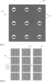
- shows a bottom view of a second embodiment of a cargo transport platform according to the present invention;
- Figure 8
- shows an arrangement of embodiments of
figure 7 on the bottom surface of a cargo container; and - Figure 9
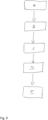
- shows the steps of a method of operating the embodiment of the cargo container shown in
figures 1 to 6 . - As can be seen in
figure 1 an aircraft 1 usually comprises afuselage 3 having a passenger cabin 5 as well as a cargo hold 7 below the cabin 5. It is desirable that cargo containers are not only stored within the cargo hold 7 but that also the passenger cabin 5 of the aircraft 1 may be used for such purpose after having removed at least part of the seat rows in the cabin. Therefore, the embodiments of cargo containers 9 as described below will have to be dimensioned such that they are able pass both the passenger door and a cargo door (not shown). - Furthermore, since at least the passenger cabin 5 is normally not provided with any means on its the floor surface to enable transport of cargo containers, it is required that these cargo containers 9 are provided with specific means so as to facilitate movement or shifting of the containers 9 along the floor surface of the passenger cabin 5, either autonomously or by personnel. In particular, the cargo containers 9 need to be adapted such that they may precisely be positioned adjacent to each other on the floor surface both of the passenger cabin 5 and of the cargo hold 7 which in turn requires that the containers are provided with means to allow for precise steering of the movement.
- As can be seen in
figures 2 to 6 a first embodiment of a cargo container 9 according to the present invention comprisescargo transport platform 11 having abase member 13 with anupper surface 15 which is adapted to be releasably coupled with the bottom surface 17 of asupport member 19. Thesupport member 19 additionally comprises asupport surface 21 which points away from the bottom surface 17 and is arranged such that when thesupport member 19 is coupled to thecargo transport platform 11 and the latter is positioned on a horizontally extendingfloor 23, it points upwards so that it is capable of supporting cargo elements. In this preferred embodiment thesupport member 19 is additionally provided with acasing 23 which encompasses a receivingspace 25 in which cargo elements may be received. However, it is also conceivable and within the scope of the present invention that thesupport member 19 does not comprise such casing. - In this regard it is to be noted that the term "cargo elements" in the sense of the present invention is to be construed broadly so that it covers any kind of cargo that may be transported by an aircraft independent of its size of the weight, i.e., it covers luggage as well as heavy cargo elements normally received in a cargo hold.
- In addition, the
base member 13 comprises alower surface 29 which during normal use points towards thefloor surface 23 of the passenger cabin 5 or the cargo hold 7. As can further be seen infigures 2 and5 , thelower surface 29 of thebase member 13 is provided with a plurality ofsteerable wheel devices 31 examples of which will be described in detail below and which comprise acarrier 33 and awheel assembly 35. In the first and second preferred embodiments described in the following thewheel assemblies 35 comprise first andsecond wheels wheel axis 41. In eachsteerable wheel device 31 thewheel assembly 35 is mounted on thecarrier 33 with thewheel axis 41 being fixed relative to thecarrier 33. Thecarrier 33 of each of thesteerable wheel devices 31 is rotatably supported in thebase member 13 of thecargo transport platform 11 about a steeringaxis 43 which extends perpendicularly to thelower surface 29 and vertically to thefloor surface 23. - As can further be seen in
figures 2 and5 , in this first embodiment of acargo transport platform 11 thecarriers 33 of each of thesteerable wheel devices 31 are provided with awedge member 45 which engages with afurther wedge member 47 fixedly mounted on one of a plurality ofparallel rods 49 that extend through thebase member 13 and are coupled to alever 51 pivotably mounted on thebase member 13. By pivoting thelever 51 therods 49 arranged in parallel are shifted so that thewedge members 47 mounted on therods 49 slide along thewedge members 45 fixed to thecarriers 33 and thecarriers 33 are retracted into or pushed out of thebase member 13 depending on the pivot position of thelever 51. Thus, thecarriers 33 are movable between a retracted position in which thewheels wheel assemblies 35 do not project beyond thelower surface 29 of thebase member 13, and an extended position (seefigure 2 ) where thewheels wheel assemblies 35 project beyond thelower surface 29 and may get in contact with therespective floor surface 23. - Thus, the
carrier 33 of each of thesteerable wheel devices 31 is movable relative to thebase member 13 parallel to therespective steering axis 43 between an extended position and a retracted position. - Moreover, as can be seen in
figures 3 and 4 , thedistal end 53 of each of therod 49 extends beyond the front end 55 of thebase member 13 of thecargo transport platform 11, when thelever 51 is pivoted towards thebase member 13 into that position in which thecarriers 33 are in the retracted position (seefigure 4 ). The distal ends 53 extending beyond the front end 55 of thebase member 13, may engage with recesses in an adjacentcargo transport platform 11 such that thecargo transport platforms 11 are locked with each other. - In the following the configuration of the plurality of
steerable wheel devices 31 on thelower surface 29 of thebase member 13 will be discussed in detail with respect tofigures 6 . - The
carrier 33 supports a shaft 57 which defines thewheel axis 41 and on which the first and thesecond wheels second wheels first wheel 37 is mounted on the shaft 57 by afirst hub drive 59 and thesecond wheel 39 by asecond hub drive 61. With this arrangement that the first and thesecond wheels second wheels wheel axis 41 is rotated about the steeringaxis 43. Hence, the first and the second hub drives 59, 61 form first and second rotary drives which in combination form a drive assembly that is capable to rotate thecarrier 33 relative to thebase member 13 about the associatedsteering axis 43. In addition, the first and the second hub drives 59, 61 drive the first and thesecond wheels wheel axis 41. - To this end the first and the second hub drives 59, 61 are connected to a
control unit 63 mounted on thebase member 13 of thecargo transport platform 11, so that the drive assembly formed by the first and the second hub drives 59, 61 of each of thesteerable wheel devices 31 may centrally be controlled. In particular, thecontrol unit 63 is coupled to each of the hub drives 59, 61 of each of thesteerable wheel devices 31. - In this embodiment the drive assembly is formed by the two hub drives 59, 61 which also effect the rotation of the
carrier 33 about the steeringaxis 43, i.e., thecarrier 33 is not directly driven about the steeringaxis 43. It is conceivable though that a steering drive is provided which is coupled to thebase member 13 and thecarrier 33, so as to effect rotation of thecarrier 33 about the steeringaxis 43. Such steering drive may be formed as a step motor. - Moreover, as shown in the
figure 6 , each of thesteerable wheel devices 31 of this embodiment comprises afirst sensor element 65 that is adapted to detect the rotational position of thecarrier 33 relative to thebase element 13. Moreover,second sensor elements 67 are provided that are configured such that they are capable of detecting the rotational position and the rotational speed of the first and thesecond wheels steerable wheel devices 31 is provided with a sensor assembly comprising the first and thesecond sensor elements carrier 33 relative to thebase member 13 as well as the rotational position of thewheels control unit 63 via connection lines so that thecontrol unit 63 is supplied with signals relating to both the position of thecarrier 33 and thewheels - As can be seen in
figure 6 that in this embodiment thecarrier 33 is coupled to thewedge member 45 which in turn engages with awedge member 47 on one of therods 49 via connectors 69 that extend through thebase member 13. With this arrangement it is achieved that the movement of therods 49 within thebase member 13 indeed effect the movement of thecarrier 33 relative to thebase member 13. Between the connectors 69 and thecarrier 33 dampeningelements 71 are provided so that they is arranged between thecarrier 33 and thebase member 13 and allow for a limited movement of thecarrier 33 relative to thebase member 13 parallel to the vertical or steeringaxis 43. Hence, the dampeningelements 71 dampen vibrations generated when thecargo transport platform 11 slides e.g. across thefloor 23 of the cargo hold or cabin of an aircraft 1. - Moreover, the
transfer platform 11 is provided with a releasably mountedbattery pack 73 which is connected with the first and second hub drives 59, 61 and thecontrol unit 63 so as to supply them with power. Thebattery pack 73 is preferably releasably mounted so that it can easily be exchanged. - In order to determine the actual position the
cargo transport platform 11 has thecontrol unit 63 is provided with a position sensor in the form ofGPS sensors 75 that provides a signal representing the actual position of the platform to thecontrol unit 63. - Finally, in order to allow for a user to input e.g., the desired target position the
cargo transport platform 11 shall move to or steering commands, a user interface 77 is provided which in this preferred embodiment is mounted on thecasing 25 of thesupport member 19. The user interface 77 is connected with thecontrol unit 63. Since in this case the user interface 77 is connected to thesupport member 19 which is releasably mounted on thecargo transport platform 11, the user interface 77 is connected to thecontrol unit 63 by means of a wireless connection. In case the user interface 77 is directly connected to the platform a wired connection can be employed. - The embodiment of a cargo container 9 shown in
figures 2 to 6 can be operated as follows wherein it is also referred to the figure 11 depicting the steps of a corresponding method of operating thecargo transport platform 11 of the container. - Initially, the
cargo transport platform 11 and that thesupport member 19 are coupled with each other and cargo elements (not shown in the drawings) are positioned on thesupport surface 21 within the receivingspace 25 defined by thecasing 25. The container 9 may be transferred into the cabin 5 or the cargo hold 7 of the aircraft 1. - Then a user may input either direct control commands into the user interface 77, such as steering commands or a desired position to which the cargo container 9 shall be moved within the cabin 5 or the cargo hold 7 (step A). In this regard is to be noted that it is also within the scope of the present invention that the respective commands are input into the
control unit 63 on a different way such as a wireless connection. Hence, the present invention is not limited to inputting the commands via a user interface. - Based on the commands input to the
control unit 63 it determines the predetermined path, i.e., the direction in which thecargo transport platform 11 is to be moved or the path how to reach the final position determined by the input (step B). - Based on the evaluation in step B, the
control unit 63 determines for each of thesteerable wheel devices 31 the rotational positions of thecarriers 33 and the required velocities, with which thewheels cargo transport platform 11 is moved along the desired predetermined path resulting from the input of the user into the user interface 77 (step C). - In particular, the
control unit 63 determines for each of thesteerable wheel devices 31 the required rotational position of thecarrier 33 and the velocity with which it shall move. Based on this it provides control signals to the first and second hub drives 59, 61 so that therespective carrier 33 is rotated into the desired position and then moved along the desired direction. - Hence, based on the steering commands or the desired position, e.g. input by a user into the user interface 77, a path is determined by the
control unit 63 along which thecargo transport platform 11 shall be moved. Based on this path thecontrol unit 63 conducts the aforementioned step for each of thesteerable wheel devices 31, i.e., it determines the rotational position of thecarrier 33 as well as the required velocity along the resulting direction. - In the following the
control unit 63 provides corresponding control signals to the first and second hub drives 59, 61 of each of the steerable wheel devices 31 (step D). Based on these control signals the hub drives 59, 61 are operated such that the rotational position of thecarriers 33 as well as the required velocities are indeed obtained (step E) wherein thesensor elements control unit 63 so as to enable a complete control process for each of thesteerable wheel devices 31. - Therefore, with this embodiment of a control method the
control unit 63 effects that the cargo transport platform is actually moved along the predetermined path initially determined by the user input or other input. - Such predetermined path may also encompass that the user simply wishes that the
cargo transport platform 11 is turned around at the position where it is actually located. In such case thecontrol unit 63 effects that by correspondingly controlling the hub drives 59, 61 of theindividual wheels steerable wheel devices 31 that thecarriers 33 are aligned and thewheels platform 11 is moved. This also includes that at an intermediate position before reaching the final position the control unit changes the predetermined path so as to consider obstacles or the like. In order to determine whether the final position as input has indeed been reached, theGPS sensor 75 may be used for control purposes. - In the
figures 7 and 8 another embodiment of a cargo transfer platform 11' is schematically shown which at itslower surface 29 also comprises a plurality ofsteerable wheel devices 31 being configured in the same manner as depicted infigure 6 . Similar to the aforementioned embodiment, thesteerable wheel devices 31 and the first and second hub drives 59, 61, respectively, are connected to acontrol unit 63 mounted on the base member and 13 of the cargo transport platform 11'. As shown infigure 8 , a plurality of the cargo transport platforms 11' can be mounted on the lower surface 17 of thesupport member 19 of a cargo container (not shown infigures 7 and 8 ) with thecontrol unit 63 of each of the cargo transport platforms 11' being connected to acentral unit 79 mounted on thesupport member 19. Thecentral unit 79 is adapted to receive an input as to the direction or final position the container with thesupport member 19 shall obtain. Based on this input thecentral unit 79 determines for each of the cargo transport platforms 11' the direction along which it shall remove and based on this individual direction, an input signal to therespective control unit 63 of each of the cargo transport platforms 11', this input signal being the input for theindividual control unit 63 of the platforms 11'. Based on this input signal thecontrol unit 63 of the individual cargo transport platforms 11' operate as explained in relation to the first embodiment, i.e., the control unit processes as described with respect tofigure 9 and provide control signals to the individualsteerable wheel devices 31. - Therefore, this modular configuration also allows for the container being provided with a plurality of cargo transport platforms to be moved in a controlled and driven manner along a predetermined path and to a desired position, respectively, on the
floor 23 of the cabin or a cargo hold of an aircraft. -
- 1
- aircraft
- 3
- fuselage
- 5
- passenger cabin
- 7
- cargo hold
- 9
- cargo container
- 11, 11'
- cargo transport platform
- 13
- base member
- 15
- upper surface
- 17
- bottom surface
- 19
- support member
- 21
- support surface
- 23
- floor
- 25
- casing
- 27
- receiving space
- 29
- lower surface
- 31
- steerable wheel device
- 33
- carrier
- 35
- wheel assembly
- 37
- first wheel
- 39
- second wheel
- 41
- wheel axis
- 43
- steering axis
- 45
- wedge member
- 47
- wedge member
- 49
- rod
- 51
- lever
- 53
- distal end
- 55
- front end
- 57
- shaft
- 59
- first hub drive
- 61
- second hub drive
- 63
- control unit
- 65
- first sensor element
- 67
- second sensor element
- 69
- connectors
- 71
- dampening element
- 73
- battery pack
- 75
- GPS sensor
- 77
- user interface
- 79
- central unit
Claims (15)
- A cargo transport platform for being received in an aircraft cargo hold (7) or cabin (5) comprising:a base member (13) having an upper surface (15) configured to support cargo elements and a lower surface (29) adapted to face a floor surface of the cargo hold (7) or cabin (5),a plurality of steerable wheel devices (31) supported in the base member (13) and adapted to allow the platform (11) to slide on the floor surface (23),wherein each of the plurality of steerable wheel devices (31) comprises a carrier (33) and a wheel assembly (35), each wheel assembly (35) comprising at least one wheel (37, 39) which is rotatably supported in the carrier (33) about a wheel axis (41) and arranged such that it projects beyond the lower surface (29),wherein for each of the steerable wheel devices (31) a steering axis(43) is defined about which the carrier (33) of said steerable wheel device (31) my rotate relative to the base member (13), each steering axis (43) extending vertically relative to the floor surface (23),wherein each steerable wheel device (31) comprises a drive assembly (59, 61) wherein the drive assembly (59, 61) is adaptedto rotate the carrier (33) of said steerable wheel device (31) about its steering axis (43) andto rotatingly drive the at least one wheel (37, 39) of the wheel assembly (35) of said steerable wheel device (31) about its wheel axis, anda control unit connected to each of the drive assemblies and adapted to provide control signals to the drive assembly so as to effect movement of the platform along a predetermined path.
- The cargo transport platform according to claim 1, wherein the wheel assembly (35) of each steerable wheel device (31) comprises a first and a second wheel (37, 39) being rotatably supported in the carrier (33) of said steerable wheel device (31) about its wheel axis (41),wherein the drive assembly of each of the steerable wheel devices (31) comprises a first rotary drive (59) coupled to the first wheel (37) and a second rotary drive (61) coupled to the second wheel (39), andwherein the control unit (63) is connected to the drive assembly such that the first and second rotary drives (59, 61) are operable in such a way that the rotational direction and rotational speed of each of the first and second wheels (37, 39) of each steerable wheel device (31) can be controlled independently.
- The cargo transport platform according to claim 2, wherein the first and the second rotary drives (59, 61) of each of the steerable wheel devices (31) are formed as a hub drive.
- The cargo transport platform according to one or more of claims 1 to 3, wherein the drive assembly of each of the steerable wheel devices (31) comprises a steering drive coupled to the base member (13) and the carrier (33) of said steerable wheel device (33) and adapted to rotate said carrier (33) about its steering axis (43).
- The cargo transport platform according to claim 4, wherein the steering drive is formed as step motor.
- The cargo transport platform according to one or more of the preceding claims, wherein in of each of the steerable wheel devices (31) a sensor assembly (65, 67) is provided which is adapted to detectthe position of the carrier (33) of said steerable wheel device (31) relative to the base member (13) and/orthe rotational position of the at least one wheel (37, 39) of the wheel assembly (35) of said steerable wheel device (31) and/orthe rotational speed of the at least one wheel (37, 39) of the wheel assembly (35) of said steerable wheel device (31), andwherein the sensor assembly (65, 67) of each of the steerable wheel devices (31) is connected to the control unit (63) and capable of transmitting a signal to the control unit (63) representingthe position of the carrier (33) of said steerable wheel device (31) relative to the base member (13) and/orthe rotational position of the at least one wheel (37, 39) of the wheel assembly (35) of said steerable wheel device (31) and/orthe rotational speed of the at least one wheel (37, 39) of the wheel assembly (35) of said steerable wheel device (31).
- The cargo transport platform according to one or more of the preceding claims, wherein a battery pack (73) is provided, which is preferably releasably mounted on the base member (13),
wherein the drive assembly of each of the steerable wheel devices (31) is adapted to be supplied by the battery pack (73). - The cargo transport platform according to one or more of the preceding claims, wherein the carrier (33) of each of the steerable wheel devices (31) is moveable relative to the base member (13) parallel to the steering axis (43) of said steerable wheel device (31) betweenan extended position in which the at least one wheel (37, 39) of said steerable wheel device (31) extends beyond the lower surface (29) anda retracted position in which the at least one wheel (37, 39) of said steerable wheel device (31) is retracted behind the lower surface (29).
- The cargo transport platform according to one or more of the preceding claims, comprising a position sensor (79) connected to the control unit (63) and adapted to provide a signal representing the actual position of the platform (11) to the control unit (63).
- The cargo transport platform according to one or more of the preceding claims, comprising a user interface (77) adapted to receive an input from a user specifying a target position and/or the predetermined path and/or a direction along which the platform (11) is to be moved by the steerable wheel devices (31).
- A cargo transport system for being received in an aircraft cargo hold (7) or cabin (5) comprisingat least one cargo transport platform (11) according to one or more of the preceding claims anda support member (19) having a support surface (21),wherein the at least one cargo transport platform (11) is connected to the support member (19),wherein the support member (19) being configured such that when the at least one wheel (37, 39) of the steerable wheel devices (31) of the at least one cargo transport platform (11) are positioned on a floor surface (23) of an aircraft cargo hold (7) or cabin (5), the support surface (23) may support cargo.
- The cargo transport system according to claim 11, wherein the base member (13) of the at least one cargo transport platform (11) is releasably connected to the support member (19).
- The cargo transport system according to claim 11, wherein the base member (13) of the at least one cargo transport platform (11) is connected to the support member (19) such, that the base member (13) and the support member (21) are integrally formed.
- Method of operating a cargo transport platform of one or more of claims 1 to 10, comprising the following steps:a) providing a control command to the control unit (63);b) determining a predetermined path to be followed by the cargo transport platform (11) based on the control command by the control unit (63);c) determining a rotational position of the carrier (33) and the velocity of the at least one wheel (37, 39) of each the steerable wheel devices (31) by the control unit (63) to obtain movement of the cargo transport platform (11) along the predetermined path;d) providing control signals to the drive assemblies of each of the steerable wheel devices (31) corresponding to the rotational position and the velocity determined in step d) by the control unit (63); ande) operating the drive assemblies of each of the steerable wheel devices (31) based on the control signals provided in step d).
- Method according to claim 14, wherein the wheel assembly (35) of each steerable wheel device (31) comprises a first and a second wheel (37, 39) being rotatably supported in the carrier (33) of said steerable wheel device (31) about its wheel axis (41), wherein the drive assembly of each of the steerable wheel devices (31) comprises a first rotary drive (59) coupled to the first wheel (37) and a second rotary drive (61) coupled to the second wheel (39), and wherein the control unit (63) is connected to the drive assembly such that the first and second rotary drives (59, 61) are operable in such a way that the rotational direction and rotational speed of each of the first and second wheels (37, 39) of each steerable wheel device (31) can be controlled independently;wherein in step d) the control signals are provided by the control unit (63) to the first and the second rotary drive (59, 61) of each of the steerable wheel devices (31); andwherein in step e) the first and the second rotary drives (59, 61) of each of the steerable wheel devices (31) are operated based on the control signals provided in step d).
Priority Applications (1)
| Application Number | Priority Date | Filing Date | Title |
|---|---|---|---|
| EP21200997.1A EP4163205A1 (en) | 2021-10-05 | 2021-10-05 | Movable cargo transport platform for being received in an aircraft cargo hold or cabin having separately steerable wheel assemblies and cargo transport system |
Applications Claiming Priority (1)
| Application Number | Priority Date | Filing Date | Title |
|---|---|---|---|
| EP21200997.1A EP4163205A1 (en) | 2021-10-05 | 2021-10-05 | Movable cargo transport platform for being received in an aircraft cargo hold or cabin having separately steerable wheel assemblies and cargo transport system |
Publications (1)
| Publication Number | Publication Date |
|---|---|
| EP4163205A1 true EP4163205A1 (en) | 2023-04-12 |
Family
ID=78078140
Family Applications (1)
| Application Number | Title | Priority Date | Filing Date |
|---|---|---|---|
| EP21200997.1A Pending EP4163205A1 (en) | 2021-10-05 | 2021-10-05 | Movable cargo transport platform for being received in an aircraft cargo hold or cabin having separately steerable wheel assemblies and cargo transport system |
Country Status (1)
| Country | Link |
|---|---|
| EP (1) | EP4163205A1 (en) |
Citations (5)
| Publication number | Priority date | Publication date | Assignee | Title |
|---|---|---|---|---|
| US5020657A (en) * | 1990-02-21 | 1991-06-04 | Bavaria Cargo Technologie Gmbh | Drive roller unit |
| EP0464981A1 (en) * | 1990-06-25 | 1992-01-08 | Teleflex Incorporated | Low profile steerable power drive unit |
| US20080310944A1 (en) * | 2007-06-14 | 2008-12-18 | Goodrich Corporation | Power drive unit with eccentric roller lift system |
| WO2014049590A1 (en) * | 2012-09-27 | 2014-04-03 | Israel Aerospace Industries Ltd. | Cargo handling system, method and apparatus |
| US10947036B2 (en) * | 2017-01-11 | 2021-03-16 | Biosphere Aerospace, Llc | Modular container transport systems |
-
2021
- 2021-10-05 EP EP21200997.1A patent/EP4163205A1/en active Pending
Patent Citations (5)
| Publication number | Priority date | Publication date | Assignee | Title |
|---|---|---|---|---|
| US5020657A (en) * | 1990-02-21 | 1991-06-04 | Bavaria Cargo Technologie Gmbh | Drive roller unit |
| EP0464981A1 (en) * | 1990-06-25 | 1992-01-08 | Teleflex Incorporated | Low profile steerable power drive unit |
| US20080310944A1 (en) * | 2007-06-14 | 2008-12-18 | Goodrich Corporation | Power drive unit with eccentric roller lift system |
| WO2014049590A1 (en) * | 2012-09-27 | 2014-04-03 | Israel Aerospace Industries Ltd. | Cargo handling system, method and apparatus |
| US10947036B2 (en) * | 2017-01-11 | 2021-03-16 | Biosphere Aerospace, Llc | Modular container transport systems |
Similar Documents
| Publication | Publication Date | Title |
|---|---|---|
| EP4115491B1 (en) | Lift device with split battery pack | |
| US6420846B1 (en) | Power drive unit with stall sensor | |
| US10427790B2 (en) | Adaptive aerial vehicle | |
| EP2590879B1 (en) | Automated guided vehicle (agv) system | |
| US10160488B2 (en) | Steering system for a vehicle and steering method for a vehicle | |
| EP3400171B1 (en) | Multirotor aircraft | |
| CN112262076A (en) | Loading structure with tether guide for unmanned aerial vehicle | |
| EP3594129B1 (en) | Work platform mover system | |
| WO2017091596A1 (en) | Mechanical tipping assembly for mobile drive unit of inventory system | |
| KR20130130116A (en) | Multi-rotor aircraft | |
| EP3611042B1 (en) | Systems, methods, and apparatuses for engaging and transporting objects | |
| EP3290330A1 (en) | System for moving loads comprising a locking arrangement that is operable by means of a transport vehicle | |
| US20090205908A1 (en) | Omni-directional aircraft and ordinance handling vehicle | |
| US10752445B2 (en) | Modular conveying unit | |
| KR20250111356A (en) | vehicle | |
| CN110667713B (en) | Self-driven logistics mobile platform | |
| US11993352B1 (en) | Seating system and seat assembly for marine vessel | |
| JP5073424B2 (en) | Aircraft ground steering apparatus and ground steering method | |
| EP1795433A1 (en) | A steering system for a vehicle | |
| KR102948979B1 (en) | Agv for transporting aircraft | |
| US20190168865A1 (en) | Nose gear steering apparatus for shipboard operations | |
| KR102454669B1 (en) | Carrying apparatus | |
| EP4163206A1 (en) | Movable cargo platform for being received in a cargo hold or cabin of an aircraft having extendable and steerable wheel assemblies | |
| CN211196413U (en) | Self-driven logistics mobile platform and universal wheel device thereof | |
| WO2025151633A1 (en) | Power-assisted unit load device transfer systems |
Legal Events
| Date | Code | Title | Description |
|---|---|---|---|
| PUAI | Public reference made under article 153(3) epc to a published international application that has entered the european phase |
Free format text: ORIGINAL CODE: 0009012 |
|
| STAA | Information on the status of an ep patent application or granted ep patent |
Free format text: STATUS: THE APPLICATION HAS BEEN PUBLISHED |
|
| AK | Designated contracting states |
Kind code of ref document: A1 Designated state(s): AL AT BE BG CH CY CZ DE DK EE ES FI FR GB GR HR HU IE IS IT LI LT LU LV MC MK MT NL NO PL PT RO RS SE SI SK SM TR |
|
| STAA | Information on the status of an ep patent application or granted ep patent |
Free format text: STATUS: REQUEST FOR EXAMINATION WAS MADE |
|
| 17P | Request for examination filed |
Effective date: 20231010 |
|
| RBV | Designated contracting states (corrected) |
Designated state(s): AL AT BE BG CH CY CZ DE DK EE ES FI FR GB GR HR HU IE IS IT LI LT LU LV MC MK MT NL NO PL PT RO RS SE SI SK SM TR |
|
| STAA | Information on the status of an ep patent application or granted ep patent |
Free format text: STATUS: EXAMINATION IS IN PROGRESS |
|
| 17Q | First examination report despatched |
Effective date: 20241002 |