EP4163160A1 - Wiper composite beam blade assembly with wash tube integration - Google Patents
Wiper composite beam blade assembly with wash tube integration Download PDFInfo
- Publication number
- EP4163160A1 EP4163160A1 EP22200277.6A EP22200277A EP4163160A1 EP 4163160 A1 EP4163160 A1 EP 4163160A1 EP 22200277 A EP22200277 A EP 22200277A EP 4163160 A1 EP4163160 A1 EP 4163160A1
- Authority
- EP
- European Patent Office
- Prior art keywords
- support member
- wash tube
- wiper blade
- clip
- blade
- Prior art date
- Legal status (The legal status is an assumption and is not a legal conclusion. Google has not performed a legal analysis and makes no representation as to the accuracy of the status listed.)
- Granted
Links
Images


Classifications
-
- B—PERFORMING OPERATIONS; TRANSPORTING
- B60—VEHICLES IN GENERAL
- B60S—SERVICING, CLEANING, REPAIRING, SUPPORTING, LIFTING, OR MANOEUVRING OF VEHICLES, NOT OTHERWISE PROVIDED FOR
- B60S1/00—Cleaning of vehicles
- B60S1/02—Cleaning windscreens, windows or optical devices
- B60S1/46—Cleaning windscreens, windows or optical devices using liquid; Windscreen washers
- B60S1/48—Liquid supply therefor
- B60S1/52—Arrangement of nozzles; Liquid spreading means
- B60S1/522—Arrangement of nozzles; Liquid spreading means moving liquid spreading means, e.g. arranged in wiper arms
- B60S1/524—Arrangement of nozzles; Liquid spreading means moving liquid spreading means, e.g. arranged in wiper arms arranged in wiper blades
-
- B—PERFORMING OPERATIONS; TRANSPORTING
- B60—VEHICLES IN GENERAL
- B60S—SERVICING, CLEANING, REPAIRING, SUPPORTING, LIFTING, OR MANOEUVRING OF VEHICLES, NOT OTHERWISE PROVIDED FOR
- B60S1/00—Cleaning of vehicles
- B60S1/02—Cleaning windscreens, windows or optical devices
- B60S1/04—Wipers or the like, e.g. scrapers
- B60S1/32—Wipers or the like, e.g. scrapers characterised by constructional features of wiper blade arms or blades
- B60S1/34—Wiper arms; Mountings therefor
- B60S1/3415—Wiper arms; Mountings therefor with means for supplying cleaning fluid to windscreen cleaners, e.g. washers
-
- B—PERFORMING OPERATIONS; TRANSPORTING
- B60—VEHICLES IN GENERAL
- B60S—SERVICING, CLEANING, REPAIRING, SUPPORTING, LIFTING, OR MANOEUVRING OF VEHICLES, NOT OTHERWISE PROVIDED FOR
- B60S1/00—Cleaning of vehicles
- B60S1/02—Cleaning windscreens, windows or optical devices
- B60S1/04—Wipers or the like, e.g. scrapers
- B60S1/32—Wipers or the like, e.g. scrapers characterised by constructional features of wiper blade arms or blades
- B60S1/38—Wiper blades
- B60S1/3806—Means, or measures taken, for influencing the aerodynamic quality of the wiper blades
- B60S1/381—Spoilers mounted on the squeegee or on the vertebra
-
- B—PERFORMING OPERATIONS; TRANSPORTING
- B60—VEHICLES IN GENERAL
- B60S—SERVICING, CLEANING, REPAIRING, SUPPORTING, LIFTING, OR MANOEUVRING OF VEHICLES, NOT OTHERWISE PROVIDED FOR
- B60S1/00—Cleaning of vehicles
- B60S1/02—Cleaning windscreens, windows or optical devices
- B60S1/04—Wipers or the like, e.g. scrapers
- B60S1/32—Wipers or the like, e.g. scrapers characterised by constructional features of wiper blade arms or blades
- B60S1/38—Wiper blades
- B60S1/3848—Flat-type wiper blade, i.e. without harness
-
- B—PERFORMING OPERATIONS; TRANSPORTING
- B60—VEHICLES IN GENERAL
- B60S—SERVICING, CLEANING, REPAIRING, SUPPORTING, LIFTING, OR MANOEUVRING OF VEHICLES, NOT OTHERWISE PROVIDED FOR
- B60S1/00—Cleaning of vehicles
- B60S1/02—Cleaning windscreens, windows or optical devices
- B60S1/04—Wipers or the like, e.g. scrapers
- B60S1/32—Wipers or the like, e.g. scrapers characterised by constructional features of wiper blade arms or blades
- B60S1/38—Wiper blades
- B60S1/3848—Flat-type wiper blade, i.e. without harness
- B60S1/3849—Connectors therefor; Connection to wiper arm; Attached to blade
- B60S1/3862—Transport of liquid there through
-
- B—PERFORMING OPERATIONS; TRANSPORTING
- B60—VEHICLES IN GENERAL
- B60S—SERVICING, CLEANING, REPAIRING, SUPPORTING, LIFTING, OR MANOEUVRING OF VEHICLES, NOT OTHERWISE PROVIDED FOR
- B60S1/00—Cleaning of vehicles
- B60S1/02—Cleaning windscreens, windows or optical devices
- B60S1/04—Wipers or the like, e.g. scrapers
- B60S1/32—Wipers or the like, e.g. scrapers characterised by constructional features of wiper blade arms or blades
- B60S1/38—Wiper blades
- B60S2001/3812—Means of supporting or holding the squeegee or blade rubber
Definitions
- the present disclosure relates to windshield wiper systems, and in particular to a windshield wiper system used on an aircraft.
- Aircraft windshield wiper systems are used to wipe and clean water or other debris from an aircraft windshield, allowing better visibility out the windshield for both the pilot and copilot.
- Windshield wiper systems include a wiper arm and a wiper blade that sweep back and forth across a windshield within specific sweep angle requirements, cleaning the windshield for the pilot and co-pilot.
- Many windshield wiper systems include a wash system that dispenses a fluid onto the windshield of the aircraft to aid in cleaning the windshield of the aircraft.
- Windshield wiper systems utilizing metallic supports have a fluid tube welded or brazed to the metallic components for providing fluid adjacent the wiper blade sweeping across the windshield.
- Windshield wiper systems utilizing composite supports cannot include welded or brazed fluid tubes and therefore there is a need for a solution to incorporate fluid tubes into composite support type wiper blade assemblies.
- a wiper blade for use on a windshield of an aircraft.
- the wiper blade includes a support member, a blade element, a clip, and a wash tube.
- the support member is coupled to the blade element, and the support member is constructed from a composite material.
- the clip is coupled to and surrounds at least a portion of the support member and at least a portion of the blade element.
- the wash tube is integral with the support member, and the wash tube is fluidly coupled to a plurality of nozzles spaced along a length of the wiper blade.
- FIG. 1A is a side view of windshield wiper system 10 on aircraft windshield 12.
- FIG. 1B is a perspective view of wiper blade 14 of windshield wiper system 10.
- FIGS. 1A-1B will be discussed together.
- windshield wiper system 10 will be referred to as WWS 10.
- WWS 10 includes wiper blade 14, wiper arm 16, output shaft 18, actuator 20, fluid source 22, and fluid line 24.
- WWS 10 is installed on an aircraft and WWS 10 is configured to clear windshield 12 of rain or other debris.
- Wiper arm 16 includes first end 16A positioned at a distal end of wiper arm 16 and second end 16B positioned at an opposite distal end of wiper arm 16 as first end 16A.
- Wiper blade 14 is coupled to first end 16A of wiper arm 16 through a coupler, discussed further below.
- Wiper arm 16 can be constructed from a polymer, a composite, a metal, or at least partially from one or more of the listed materials.
- Wiper arm 16 is coupled to output shaft 18 at second end 16B of wiper arm 16 through a mechanical connection, such as a threaded or clamping connection.
- Output shaft 18 extends through a body portion of the aircraft adjacent windshield 12 but not through windshield 12.
- Output shaft 18 is configured to rotate about its central axis, providing rotational energy to second end 16B of wiper arm 16, which in turn forces wiper arm 16 and wiper blade 14 to traverse across windshield 12 in a sweeping motion.
- Actuator 20 is coupled to output shaft 18 within the body portion of the aircraft. Actuator 20 is configured to provide rotational energy to output shaft 18, rotating output shaft 18 about its central axis.
- actuator 20 provides the energy necessary to drive motion of WWS 10.
- actuator 20 is a brushless direct current motor.
- actuator 20 can be a brushed direct current motor or any other motor configured to provide rotational energy to output shaft 18.
- actuator 20 is a bi-directional motor that can operate in both directions, allowing output shaft 18, wiper arm 16, and wiper blade 14 to travel across windshield 12 in both directions.
- fluid source 22 can be an impermeable vessel of any shape, size, and material that is configured to store the fluid that will be dispensed onto windshield 12.
- fluid source 22 can be a leak proof container that includes a hollow interior configured to store fluids before the fluids are used by WWS 10.
- fluid source 22 can be a flow path from a portion of an engine, compressor, auxiliary power unit, or any other hot air source within the aircraft, such as for example to provide engine bleed air to WWS 10.
- Fluid source 22 is positioned within the aircraft body and fluidly coupled to wiper blade 14 through fluid line 24, discussed further below. Fluid line 24 extends from fluid source 22 to wiper blade 14.
- Fluid line 24 can be a tube, channel, hose, or any other component capable of transferring a fluid from fluid source 22 to wiper blade 14.
- the fluid transferring through fluid line 24 can be one or more of water, windshield cleaning fluid, chemical rain repellant, and hot engine bleed air, among other options.
- Fluid line 24 is configured to provide a flow path for fluid to flow from fluid source 22 to wiper blade 14, allowing the fluid to dispense onto windshield 12 adjacent wiper blade 14.
- fluid line 24 is coupled to wiper blade 14 at approximately the center of wiper blade 14, with respect to the length of wiper blade 14.
- fluid line 24 can be coupled to wiper blade 14 at any location along the length of wiper blade 14.
- wiper blade 14 includes support member 26, blade element 28, clips 30, wash tube 32, coupler 34, center support 36, and fastener 38.
- Support member 26 is coupled to blade element 28 and clip 30 is coupled to and surrounds at least a portion of support member 26 and at least a portion of blade element 28.
- coupler 34 is coupled to and surrounds at least a portion of support member 26 and at least a portion of blade element 28.
- Fastener 38 extends through blade element 28 and clip 30, securing clip 30 to blade element 28.
- Support member 26 is a structural component that provides rigidity to wiper blade 14 during operation of WWS 10.
- support member 26 includes a rectangular cross-section extending the length of wiper blade 14, providing stiffness and rigidity to wiper blade 14 to prevent undesirable deflection of wiper blade 14 in the sweeping directions.
- support member 26 can include a cross-section of any shape that extends a full or partial length of wiper blade 14.
- Support member 26 can be constructed from a composite material, metallic material, or polymer material.
- support member 26 can be constructed from a carbon fiber reinforced polymer.
- Support member 26 is coupled to blade element 28 through an adhesive positioned between support member 26 and blade element 28 and extending a substantial length of support member 26.
- the adhesive used to couple support member 26 to blade element 28 is a polyurethane adhesive.
- Blade element 28 is the component of wiper blade 26 that is configured to interface with windshield 12 to clear windshield 12 of water or other debris.
- Blade element 28 has a complex cross-sectional shape including a rectangular top portion and a generally triangular bottom portion configured to contact and clean windshield 12 on the aircraft.
- Blade element 28 can be constructed from a rubber material, such as in one example blade element 28 is constructed from a nitrile rubber.
- blade element 28 can have a length that is less than a length of support member 26. During the adhesion of support member 26 to blade element 28, blade element 28 is stretched which causes support member 26 to flex into a curved configuration, conforming to the shape of windshield 12. In other examples, blade element 28 can have the same length as support member 26.
- Clip 30 is a component of wiper blade 14 that is configured to provide additional attachment support between support member 26 and blade element 28. More specifically, clip 30 is coupled to both support member 26 and blade element 28, and clip 30 surrounds at least a portion of each of support member 26 and blade element 28. Clip 30 is configured to exert a clamping force on support member 26 and blade element 28, compressing support member 26 and blade element 28 together.
- Clip 30 can be constructed from a metal, a polymer, or a composite material. In one example, clip 30 can be constructed from a spring steel or sheet metal to facilitate the clamping force exerted on support member 26 and blade element 28.
- wiper blade 14 includes four clips 30 coupled to support member 26 and blade element 28.
- wiper blade 14 can include more or less than four clips 30 coupled to support member 26 and blade element 28.
- the number of clips 30 coupled to wiper blade 14 depends on various factors, such as the length of wiper blade 14 and the forces exerted on wiper blade 14, among other factors.
- wiper blade 14 includes two inner clips 30 spaced equidistance from coupler 34 and two outer clips 30 adjacent the ends of wiper blade 26 that are also spaced equidistance from coupler 34. Further, in the example shown, there are an equal number of clips 30 positioned on each side of center support 36. In another example, there can be an unequal number of clips 30 positioned on each side of center support 36.
- Coupler 34 is positioned at a center position with respect to a length of support member 26 and coupler 34 extends outward from support member 26 in a direction opposite of blade element 28. Similar to clip 30, coupler 34 is coupled to and surrounds at least a portion of support member 26 and at least a portion of blade element 28. Coupler 34 is configured to couple to support member 26 and blade element 28 at one end and couple to first end 16A of wiper arm 16 at the other end. As such, coupler 34 is configured to secure wiper blade 14 to wiper arm 16 of WWS 10. Coupler 34 can be coupled to wiper arm 16 through one or more of a rivet, bolt and nut, pin and clevis, and pin and clamp, among other options. In the embodiment shown, coupler 34 is constructed from a metallic material. In other embodiments, coupler 34 can be constructed from a polymer or a composite material, among other options.
- Center support 36 is positioned adjacent and coupled to coupler 34. More specifically, center support 36 is positioned at a center position with respect to a length of support member 26 and center support 36 is coupled to coupler 34 through a weld or brazed joint. As such, in the embodiment shown, center support 36 is constructed from a metallic material, such as for example a stainless steel. In other embodiments, center support 36 can be constructed from a polymer or a composite material, among other options. Center support 36 is also coupled to wash tube 32 and center support 36 is configured to secure wash tube 32 to wiper blade 14 as well as provide additional support to wash tube 32. In the embodiment shown, center support 36 is coupled to wash tube 32 through a weld or brazed joint. In another embodiment, center support 36 can be coupled to wash tube 32 through a fastener, clamp, or adhesive, among other options.
- wash tube 32 is coupled to center support 36, securing wash tube 32 to wiper blade 14. Further, wash tube 32 is positioned adjacent support member 26 and coupled to support member 26 of wiper blade 14 through clips 30, such that wash tube 32 is integral with support member 26. In the context of the present application, "integral" means forming a part of the same assembly. Using this definition, wash tube 32 is integral with support member 26 because wash tube 32 is coupled to support member 26 using clips 30. As such, wash tube 32 is part of the assembly shown as wiper blade 14. Wash tube 32 is secured to wiper blade 14 adjacent the initial sweep side of wiper blade 14. In other words, if wiper blade 14 initially sweeps in a left direction when activated, wash tube 32 is also positioned on the left side of wiper blade 14.
- wash tube 32 is also positioned on the right side of wiper blade 14.
- Wash tube 32 is a tubular component that includes a hollow center portion, allowing fluids to flow through the center of wash tube 32.
- wash tube 32 has a circular cross-sectional shape when viewing in the axial direction of wash tube 32.
- wash tube 32 can have any desired cross-sectional shape when viewing in the axial direction of wash tube 32.
- wash tube 32 is constructed from a metallic material, such as for example stainless steel, allowing wash tube 32 to be coupled to center support 36 through a weld or brazed joint.
- wash tube 32 can be constructed from a polymer or a composite material, among other options.
- Wash tube 32 includes end caps 40 positioned at each distal end of wash tube 32, preventing fluid from flowing out through each distal end of wash tube 32.
- End caps 40 can be coupled to wash tube 32 through one or more of a friction fit, an adhesive, and a weld or brazed joint, among other fluid tight options.
- end caps 40 have an outer diameter that is larger than the outer diameter of wash tube 32, which aids in preventing wash tube 32 from translating and sliding out from the outermost clips 30 secured to wiper blade 14.
- the outer diameter of end caps 40 may not be larger than the outer diameter of wash tube 32.
- end caps 40 have a circular cross-sectional shape when viewing in the axial direction of end caps 40.
- end caps 40 can have any desired cross-sectional shape that conforms to the outer shape of wash tube 32. Further, in the embodiment shown, end caps 40 are constructed from a metallic material, such as for example stainless steel, allowing end caps 40 to be coupled to wash tube 32 through a weld or brazed joint. In other embodiments, end caps 40 can be constructed from a polymer or a composite material, among other options.
- Wash tube 32 also includes a plurality of nozzles 42 extending through wash tube 32, providing a location in which the fluid flowing through the hollow center portion of wash tube 32 can dispense or exit wash tube 32 onto windshield 12 of the aircraft.
- each nozzle 42 can be an aperture extending through an outer wall of wash tube 32.
- Nozzles 42 are configured to increase the pressure and velocity of the fluid as the fluid dispenses through nozzles 42 of wash tube 32.
- wash tube 32 includes twelve nozzles 42 spaced along a length of wash tube 32.
- wash tube 32 can include more or fewer than twelve nozzles 42 spaced along the length of wash tube 32. The number of nozzles 42 will vary depending on the length of wiper blade 14 and the fluid requirements for each specific application. As such, wash tube 32 receives a fluid from fluid line 24 fluidly coupled to wash tube 32, the fluid flows into the center hollow portion of wash tube 32, and then the fluid dispenses through the plurality of nozzles 42 onto windshield 12 of the aircraft.
- FIG. 2A is a close-up perspective view of an end portion of wiper blade 14.
- FIG. 2B is a perspective view of clip 30 of wiper blade 14.
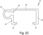
- FIG. 2C is a front view of clip 30 of wiper blade 14.
- Clip 30 includes first side 44, second side 46, top 48, first extension 50, second extension 52, first aperture 54, second aperture 56, and clamp 58.
- Clip 30 is a component of wiper blade 14 configured to secure other components of wiper blade 14 together. More specifically, clip 30 secures support member 26 and blade element 28 together through a compressive force exerted by clip 30. In addition, clip 30 secures and couples wash tube 32 to wiper blade 14 adjacent support member 26 during operation of WWS 10, discussed below.
- Clip 30 can be constructed from a composite material, metallic material, or polymer-based material.
- clip 30 is constructed from a metallic material, such as for example sheet metal, and formed using various bending operations.
- clip 30 can be manufactured using other methods, such as for example additive manufacturing and machining operations, among other options.
- First side 44 is a side portion/wall of clip 30, and second side 46 is a side portion/wall of clip 30 that is oriented offset from and parallel to first side 44.
- Top 48 extends perpendicular to first side 44 and second side 46. Further, top 48 extends between and connects first side 44 and second side 46.
- First extension 50 extends inward from first side 44 toward a center portion of clip 30. First extension 50 extends inward only a partial distance and does not connect to second side 46, leaving a gap or opening for a portion of blade element 28 to extend through. First extension 50 is oriented parallel to top 48 and perpendicular to first side 44. Second extension 52 extends inward from second side 46 toward a center portion of clip 30.
- Second extension 52 extends inward only a partial distance and does not connect to first side 44, leaving a gap or opening for a portion of blade element 28 to extend through. Second extension 52 is oriented parallel to top 48 and perpendicular to second side 46. When clip 30 is installed on and secured to support member 26 and blade element 28 of wiper blade 14, first extension 50 and second extension 52 engage a portion of blade element 28 to produce the compressive force on support member 26 and blade element 28.
- First aperture 54 extends through first side 44 of clip 30 and second aperture 56 extends through second side 46 of clip 30.
- First aperture 54 and second aperture 56 can be a hole that extends fully through first side 44 and second side 46, respectively, such that a central axis of first aperture 54 is axially aligned with a central axis of second aperture 56.
- First aperture 54 and second aperture 56 are configured to provide a location to couple clips 30 to blade element 28. Clips 30 are installed on wiper blade 14 by inserting clips 30 over the distal ends of wiper blade 14 and then positioning clips 30 at the desired location on wiper blade 14.
- clips 30 are slid down support member 26 and blade element 28 until first aperture 54 and second aperture 56 of clip 30 are aligned with a desired one of the plurality of blade element apertures spaced along the length and extending through blade element 28.
- fastener 38 is inserted through each of the apertures and secures clip 30 to blade element 28.
- Fastener 38 can extend through each clip 30 coupled to support member 26 and blade element 28.
- the number of fasteners 38 will depend on the number of clips 30 on wiper blade 14.
- Fastener 38 can be a rivet, bolt and nut, pin and clevis, pin and clamp, among other options.
- Fastener 38 is configured to extend through only clip 30 and the rectangular top portion of blade element 28 to secure clip 30 to blade element 28, which further secures support member 26 and blade element 28 together in compression. Fastener 38 does not extend through support member 26 in an effort to eliminate apertures within support member 26. Any apertures extending through support member 26 could reduce the rigidity and stiffness of support member 26, limiting the usefulness of support member 26 during operation of WWS 10. A support member 26 including apertures could result in increased deflection of wiper blade 14 during operation of WWS 10, as compared to a wiper blade 14 without apertures extending through support member 26. Increased deflection of wiper blade 14 could result in damage to wiper blade 14 and/or a nonconforming WWS 10 based on unsatisfactory sweep angle limits. As such, it is advantageous for WWS 10 to avoid or eliminate apertures extending through support member 26 to reduce deflection of wiper blade 14 during operation of WWS 10.
- Clip 30 includes clamp 58 extending outward from first side 44 of clip 30.
- Clamp 58 is the feature of clip 30 that is configured to couple wash tube 32 to clip 30 and the overall wiper blade 14.
- clamp 58 has a generally circular cross-section to conform to the circular cross-section of wash tube 32.
- clamp 58 can have any cross-sectional shape that conforms with the cross-sectional shape of wash tube 32.
- clamp 58 has an inner diameter that is approximately equal to an outer diameter of wash tube 32, allowing clamp 58 to secure and hold wash tube 32 in place during operation of WWS 10.
- Clamp 58 further includes entry 60, which extends through first side 44 of clip 30.
- Entry 60 of clamp 58 is configured to provide a location in which wash tube 32 is inserted into clamp 58. As shown in FIG. 2C , entry 60 is an opening that allows wash tube 32 to snap fit into clamp 58. The height of the opening of entry 60, parallel to first side 44, is less than the outer diameter of wash tube 32, requiring wash tube 32 to be forced through entry 60 to be seated within clamp 58. Entry 60 being less than the outer diameter of wash tube 32 secures wash tube 32 within clamp 58 and prevents wash tube 32 from falling out of clamp 58 during operation of WWS 10.
- the aircraft windshield washing system benefits from the decreased over-sweep and under-sweep by utilizing the composite support member 26 and also benefits from the capability to dispense a fluid onto windshield 12 of the aircraft to aid in cleaning windshield 12 to improve visibility for both the pilot and copilot operating the aircraft.
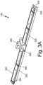
- FIG. 3A is a perspective view of an example wiper blade 140 of windshield wiper system 10.
- FIG. 3B is a perspective view of the composite support member 260 of wiper blade 140.
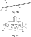
- FIG. 3C is a close-up perspective view of wiper blade 140 with blade element 280 removed for clarity.
- FIGS. 3A-3C will be discussed together.
- wiper blade 140 includes support member 260, blade element 280, clips 300, wash tube 320, coupler 340, and fastener 380.
- Support member 260 is coupled to blade element 280 and clip 300 is coupled to and surrounds at least a portion of support member 260 and at least a portion of blade element 280.
- coupler 340 is coupled to and surrounds at least a portion of support member 260 and at least a portion of blade element 280.
- Fastener 380 extends through blade element 280 and clip 300, securing clip 300 to blade element 280.
- Support member 260 is a structural component that provides rigidity to wiper blade 140 during operation of WWS 10.
- support member 260 includes a generally triangular cross-section extending the length of wiper blade 140, providing stiffness and rigidity to wiper blade 140 to prevent undesirable deflection of wiper blade 140 in the sweeping directions.
- support member 260 can include a cross-section of any shape that extends a full or partial length of wiper blade 140.
- Support member 260 can be constructed from a composite material, metallic material, or polymer material.
- support member 260 can be constructed from a carbon fiber reinforced polymer.
- Support member 260 is coupled to blade element 280 through an adhesive positioned between support member 260 and blade element 280 and extending a substantial length of support member 260.
- the adhesive used to couple support member 260 to blade element 280 is a polyurethane adhesive.
- Blade element 280 is the component of wiper blade 260 that is configured to interface with windshield 12 to clear windshield 12 of water or other debris.
- Blade element 280 has a complex cross-sectional shape including a rectangular top portion and a generally triangular bottom portion configured to contact and clean windshield 12 on the aircraft.
- Blade element 280 can be constructed from a rubber material, such as in one example blade element 280 is constructed from a nitrile rubber.
- blade element 280 can have a length that is less than a length of support member 260. During the adhesion of support member 260 to blade element 280, blade element 280 is stretched which causes support member 260 to flex into a curved configuration, conforming to the shape of windshield 12. In other examples, blade element 280 can have the same length as support member 260.
- Clip 300 is a component of wiper blade 140 that is configured to provide additional attachment support between support member 260 and blade element 280. More specifically, clip 300 is coupled to both support member 260 and blade element 280, and clip 300 surrounds at least a portion of each of support member 260 and blade element 280. Clip 300 is configured to exert a clamping force on support member 260 and blade element 280, compressing support member 260 and blade element 280 together. Fastener 380 is configured to extend through only clip 300 and the rectangular top portion of blade element 280 to secure clip 300 to blade element 280, which further secures support member 260 and blade element 280 together in compression. Fastener 380 does not extend through support member 260 in an effort to eliminate unnecessary apertures within support member 260.
- Fastener 380 can extend through each clip 300 coupled to support member 260 and blade element 280. As such, in an embodiment including four clips 300, there will be four fasteners 380 securing the four clips 300 to support member 260 and blade element 280. The number of fasteners 380 will depend on the number of clips 300 on wiper blade 140. Fastener 380 can be a rivet, bolt and nut, pin and clevis, pin and clamp, among other options.
- Clip 300 can be constructed from a metal, a polymer, or a composite material. In one example, clip 300 can be constructed from a spring steel or sheet metal to facilitate the clamping force exerted on support member 260 and blade element 280. In the embodiment shown in FIG. 3A , wiper blade 140 includes four clips 300 coupled to support member 260 and blade element 280. In another example, wiper blade 140 can include more or less than four clips 300 coupled to support member 260 and blade element 280. The number of clips 300 coupled to wiper blade 140 depends on various factors, such as the length of wiper blade 140 and the forces exerted on wiper blade 140, among other factors.
- wiper blade 140 includes two inner clips 300 spaced equidistance from coupler 340 and two outer clips 300 adjacent the ends of wiper blade 260 that are also spaced equidistance from coupler 340. Further, in the example shown, there are an equal number of clips 300 positioned on each side of center support 360. In another example, there can be an unequal number of clips 300 positioned on each side of center support 360.
- Coupler 340 is positioned at a center position with respect to a length of support member 260 and coupler 340 extends outward from support member 260 in a direction opposite of blade element 280. Similar to clip 300, coupler 340 is coupled to and surrounds at least a portion of support member 260 and at least a portion of blade element 280. Coupler 340 is configured to couple to support member 260 and blade element 280 at one end and couple to first end 16A of wiper arm 16 at the other end. As such, coupler 340 is configured to secure wiper blade 140 to wiper arm 16 of WWS 10 ( FIG. 1A ).
- Coupler 340 can be coupled to wiper arm 16 through one or more of a rivet, bolt and nut, pin and clevis, and pin and clamp, among other options.
- coupler 340 is constructed from a metallic material.
- coupler 340 can be constructed from a polymer or a composite material, among other options.
- wash tube 320 is an aperture that extends fully through support member 260, from one end of support member 260 to the other end of support member 260.
- wash tube 320 is integral with and positioned within support member 260.
- wash tube 320 is integral with support member 260 because wash tube 320 is positioned within support member 260.
- wash tube 320 is part of the assembly shown as wiper blade 140.
- Wash tube 320 is a tubular feature through a center portion of support member 260 that allows fluids to flow through wash tube 320 within support member 260.
- wash tube 320 has a circular cross-sectional shape when viewing in the axial direction of wash tube 320.
- wash tube 320 can have any desired cross-sectional shape when viewing in the axial direction of wash tube 320.
- wiper blade 140 also includes plugs 400 positioned at each distal end of wash tube 320. More specifically, plugs 400 are inserted within the ends of wash tube 320 and plugs 400 prevent fluid from flowing out through each distal end of wash tube 320. Plugs 400 can be coupled to wash tube 320 through one or more of a friction fit, an adhesive, and a composite fusion process, among other fluid tight options. In the embodiment shown, end caps 400 have an outer diameter that is smaller than the outer diameter of wash tube 320, which allows plugs 400 to be inserted within wash tube 320.
- end caps 400 have a circular cross-sectional shape when viewing in the axial direction of end caps 400.
- end caps 400 can have any desired cross-sectional shape that conforms to the outer shape of wash tube 320.
- end caps 400 can be constructed from the same or similar composite material as support member 260.
- Wiper blade 140 also includes a plurality of nozzles 420 and fluid input 440 ( FIG. 3B ).
- Nozzles 420 extend through support member 260, providing a location in which the fluid flowing through wash tube 320 can dispense or exit wash tube 320 onto windshield 12 of the aircraft.
- each nozzle 420 can be an aperture extending through support member 260.
- Nozzles 420 are configured to increase the pressure and velocity of the fluid as the fluid dispenses through nozzles 420.
- support member 260 includes eight nozzles 420 spaced along a length of support member 260. In another embodiment, support member 260 can include more or fewer than eight nozzles 420 spaced along the length of support member 260.
- nozzles 420 will vary depending on the length of wiper blade 140 and the fluid requirements for each specific application. Further, nozzles 420 are positioned adjacent the initial sweep side of wiper blade 140. In other words, if wiper blade 140 initially sweeps in a left direction when activated, nozzles 420 are also positioned on the left side of wiper blade 140. Likewise, if wiper blade 140 initially sweeps in a right direction when activated, nozzles 420 are also positioned on the right side of wiper blade 140. Positioning nozzles 420 on the initial sweep side of wiper blade 140 allows fluid to dispense onto windshield 12 in front of wiper blade 140 before wiper blade 140 sweeps across an area of windshield 12.
- fluid input 440 is an aperture that extends through support member 260 and connects to wash tube 320.
- Fluid input 440 is positioned at approximately the center of support member 260 in the lengthwise direction of support member 260. Fluid input 440 fluidly connects fluid line 24 ( FIG. 1A ) and wash tube 320, providing a flow path for fluid to flow from fluid line 24 into wash tube 320. More specifically, referring to FIG. 3C , fluid flows from fluid line 24 into input port 460, and then the fluid flows from input port 460 into fluid input 440 of support member 260.
- Input port 460 is a tube, channel, or the like, that extends through and is coupled to coupler 340.
- input port 460 extends through an aperture within coupler 340 and input port 460 is coupled to coupler 340 through a braze or weld connection.
- input port 460 and coupler 340 can be constructed from a metallic material, facilitating the brazing or welded connection between the components.
- the end of input port 460 extending within fluid input 440 of support member 260 is coupled to support member 260 through an adhesive connection. Brazing or welding input port 460 to coupler 340 and coupling input port 460 to support member 260 through an adhesive provides additional support and connection between support member 260 and coupler 340.
- Input port 460 provides a connection and flow path between fluid line 24 and fluid input 440, allowing fluid to flow from fluid input 24 through input port 460 and into fluid input 440.
- fluid is transferred from fluid source 22 through fluid line 24, the fluid travels through fluid line 24 to input port 460, the fluid flows through input port 460 and into fluid input 440, the fluid flows through fluid input 440 and into wash tube 320, and then the fluid flows through wash tube 320 and dispenses through the plurality of nozzles 420 onto windshield 12 of the aircraft.
- the aircraft windshield washing system benefits from the decreased over-sweep and under-sweep by utilizing the composite support member 260 and also benefits from the capability to dispense a fluid onto windshield 12 of the aircraft to aid in cleaning windshield 12 to improve visibility for both the pilot and copilot operating the aircraft.
- a wiper blade for use on a windshield of an aircraft comprising: a support member coupled to a blade element, wherein the support member is constructed from a composite material; a clip coupled to and surrounding at least a portion of the support member and at least a portion of the blade element; and a wash tube integral with the support member, wherein the wash tube is fluidly coupled to a plurality of nozzles spaced along a length of the wiper blade.
- the wiper blade of the preceding paragraph can optionally include, additionally and/or alternatively, any one or more of the following features, configurations and/or additional components:
- the wash tube receives a fluid from a fluid line fluidly coupled to the wash tube, and wherein the wash tube dispenses the fluid through the plurality of nozzles onto the windshield of the aircraft.
- a coupler coupled to and surrounding at least a portion of the support member and at least a portion of the blade element.
- the wiper blade comprises a plurality of clips, and wherein an equal number of clips are positioned on each side of the coupler.
- At least two clips are coupled to and surrounding at least a portion of the support member and at least a portion of the blade element, and wherein the at least two clips are spaced equidistant from the coupler.
- a center support is positioned at a center location of the support member with respect to a length of the support member, and wherein the center support is coupled to the coupler, and wherein the center support is coupled to the wash tube through a weld or brazed joint.
- the wash tube is positioned adjacent the support member and coupled to the clip.
- the clip comprises a clamp extending outwards from a first side of the clip, and wherein the clamp couples the wash tube to the clip.
- An inner diameter of the clamp is equal to an outer diameter of the wash tube; the clamp comprises an entry extending through the first side of the clip; and a height of the entry in a direction parallel to the first side is less than the outer diameter of the wash tube.
- the wash tube includes end caps positioned at each distal end of the wash tube; the end caps are coupled to the wash tube through a weld or brazed joint; and a diameter of the end caps is larger than a diameter of the wash tube.
- the clip comprises a first extension extending inward from a first side of the clip and a second extension extending inward from a second side of the clip; and the first extension is perpendicular to the first side and the second extension is perpendicular to the second side.
- the first extension and the second extension engage the blade element when the clip is coupled to the blade element.
- the clip comprises a first aperture extending through a first side of the clip and a second aperture extending through a second side of the clip; and wherein a central axis of the first aperture is axially aligned with a central axis of the second aperture.
- a fastener extends through the first aperture, the second aperture, and a blade aperture extending through the blade element to secure the clip to the blade element.
- the wash tube is an aperture that extends fully through the support member, from a first end of the support member to the second end of the support member.
- a plug positioned at each distal end of the wash tube, wherein an outer diameter of the plugs are smaller than an outer diameter of the wash tube, and wherein the plugs are inserted into the distal ends of the wash tube.
- the plurality of nozzles are apertures that extend through the support member, and wherein the plurality of nozzles are spaced along a length of the support member.
- a fluid input extending into the support member and fluidly connecting to the wash tube within the support member.
- the fluid input is an aperture that is positioned at approximately a center of the support member with respect to a length of the support member
- An input port axially aligned with and coupled to the fluid input of the support member, wherein the input port fluidly couples the fluid input of the support member to a fluid source.
Landscapes
- Engineering & Computer Science (AREA)
- Mechanical Engineering (AREA)
- Water Supply & Treatment (AREA)
- Physics & Mathematics (AREA)
- Fluid Mechanics (AREA)
- Quality & Reliability (AREA)
- Mutual Connection Of Rods And Tubes (AREA)
- Body Structure For Vehicles (AREA)
Abstract
Description
- The present disclosure relates to windshield wiper systems, and in particular to a windshield wiper system used on an aircraft.
- Aircraft windshield wiper systems are used to wipe and clean water or other debris from an aircraft windshield, allowing better visibility out the windshield for both the pilot and copilot. Windshield wiper systems include a wiper arm and a wiper blade that sweep back and forth across a windshield within specific sweep angle requirements, cleaning the windshield for the pilot and co-pilot. Many windshield wiper systems include a wash system that dispenses a fluid onto the windshield of the aircraft to aid in cleaning the windshield of the aircraft. Windshield wiper systems utilizing metallic supports have a fluid tube welded or brazed to the metallic components for providing fluid adjacent the wiper blade sweeping across the windshield. Windshield wiper systems utilizing composite supports cannot include welded or brazed fluid tubes and therefore there is a need for a solution to incorporate fluid tubes into composite support type wiper blade assemblies.
- According to one aspect of the disclosure, a wiper blade for use on a windshield of an aircraft is disclosed. The wiper blade includes a support member, a blade element, a clip, and a wash tube. The support member is coupled to the blade element, and the support member is constructed from a composite material. The clip is coupled to and surrounds at least a portion of the support member and at least a portion of the blade element. The wash tube is integral with the support member, and the wash tube is fluidly coupled to a plurality of nozzles spaced along a length of the wiper blade.
-
-
FIG. 1A is a side view of a windshield wiper system on an aircraft windshield. -
FIG. 1B is a perspective view of a wiper blade of the windshield wiper system. -
FIG. 2A is a close-up perspective view of an end portion of the wiper blade ofFIG. 1B . -
FIG. 2B is a perspective view of a clip of the wiper blade ofFIG. 1B . -
FIG. 2C is a front view of the clip of the wiper blade ofFIG. 1B . -
FIG. 3A is a perspective view of another example wiper blade of the windshield wiper system. -
FIG. 3B is a perspective view of the composite support of the example wiper blade ofFIG. 3A . -
FIG. 3C is a close-up perspective view of the example wiper blade ofFIG. 3A . -
FIG. 1A is a side view ofwindshield wiper system 10 onaircraft windshield 12.FIG. 1B is a perspective view ofwiper blade 14 ofwindshield wiper system 10.FIGS. 1A-1B will be discussed together. Further, hereinafterwindshield wiper system 10 will be referred to as WWS 10. WWS 10 includeswiper blade 14,wiper arm 16,output shaft 18,actuator 20,fluid source 22, andfluid line 24. WWS 10 is installed on an aircraft and WWS 10 is configured to clearwindshield 12 of rain or other debris.Wiper arm 16 includesfirst end 16A positioned at a distal end ofwiper arm 16 andsecond end 16B positioned at an opposite distal end ofwiper arm 16 asfirst end 16A.Wiper blade 14 is coupled tofirst end 16A ofwiper arm 16 through a coupler, discussed further below.Wiper arm 16 can be constructed from a polymer, a composite, a metal, or at least partially from one or more of the listed materials. -
Wiper arm 16 is coupled tooutput shaft 18 atsecond end 16B ofwiper arm 16 through a mechanical connection, such as a threaded or clamping connection.Output shaft 18 extends through a body portion of the aircraftadjacent windshield 12 but not throughwindshield 12.Output shaft 18 is configured to rotate about its central axis, providing rotational energy tosecond end 16B ofwiper arm 16, which in turn forceswiper arm 16 andwiper blade 14 to traverse acrosswindshield 12 in a sweeping motion.Actuator 20 is coupled tooutput shaft 18 within the body portion of the aircraft.Actuator 20 is configured to provide rotational energy tooutput shaft 18, rotatingoutput shaft 18 about its central axis. The rotation ofoutput shaft 18forces wiper arm 16 andwiper blade 14 to traverse acrosswindshield 12 in a sweeping motion, thereforeactuator 20 provides the energy necessary to drive motion of WWS 10. In the embodiment shown,actuator 20 is a brushless direct current motor. In another embodiment,actuator 20 can be a brushed direct current motor or any other motor configured to provide rotational energy to outputshaft 18. Further,actuator 20 is a bi-directional motor that can operate in both directions, allowingoutput shaft 18,wiper arm 16, andwiper blade 14 to travel acrosswindshield 12 in both directions. - In one example,
fluid source 22 can be an impermeable vessel of any shape, size, and material that is configured to store the fluid that will be dispensed ontowindshield 12. In other words,fluid source 22 can be a leak proof container that includes a hollow interior configured to store fluids before the fluids are used by WWS 10. In other examples,fluid source 22 can be a flow path from a portion of an engine, compressor, auxiliary power unit, or any other hot air source within the aircraft, such as for example to provide engine bleed air to WWS 10.Fluid source 22 is positioned within the aircraft body and fluidly coupled towiper blade 14 throughfluid line 24, discussed further below.Fluid line 24 extends fromfluid source 22 towiper blade 14.Fluid line 24 can be a tube, channel, hose, or any other component capable of transferring a fluid fromfluid source 22 towiper blade 14. The fluid transferring throughfluid line 24 can be one or more of water, windshield cleaning fluid, chemical rain repellant, and hot engine bleed air, among other options.Fluid line 24 is configured to provide a flow path for fluid to flow fromfluid source 22 towiper blade 14, allowing the fluid to dispense ontowindshield 12adjacent wiper blade 14. In the embodiment shown,fluid line 24 is coupled towiper blade 14 at approximately the center ofwiper blade 14, with respect to the length ofwiper blade 14. In another embodiment,fluid line 24 can be coupled towiper blade 14 at any location along the length ofwiper blade 14. - Referring to
FIG. 1B ,wiper blade 14 includessupport member 26,blade element 28, clips 30, washtube 32,coupler 34,center support 36, andfastener 38.Support member 26 is coupled toblade element 28 andclip 30 is coupled to and surrounds at least a portion ofsupport member 26 and at least a portion ofblade element 28. Likewise,coupler 34 is coupled to and surrounds at least a portion ofsupport member 26 and at least a portion ofblade element 28.Fastener 38 extends throughblade element 28 andclip 30, securingclip 30 toblade element 28. Each respective component will be discussed further below. -
Support member 26 is a structural component that provides rigidity towiper blade 14 during operation ofWWS 10. In the embodiment shown,support member 26 includes a rectangular cross-section extending the length ofwiper blade 14, providing stiffness and rigidity towiper blade 14 to prevent undesirable deflection ofwiper blade 14 in the sweeping directions. In another embodiment,support member 26 can include a cross-section of any shape that extends a full or partial length ofwiper blade 14.Support member 26 can be constructed from a composite material, metallic material, or polymer material. In one example,support member 26 can be constructed from a carbon fiber reinforced polymer.Support member 26 is coupled toblade element 28 through an adhesive positioned betweensupport member 26 andblade element 28 and extending a substantial length ofsupport member 26. In one example, the adhesive used to couplesupport member 26 toblade element 28 is a polyurethane adhesive. -
Blade element 28 is the component ofwiper blade 26 that is configured to interface withwindshield 12 to clearwindshield 12 of water or other debris.Blade element 28 has a complex cross-sectional shape including a rectangular top portion and a generally triangular bottom portion configured to contact andclean windshield 12 on the aircraft.Blade element 28 can be constructed from a rubber material, such as in oneexample blade element 28 is constructed from a nitrile rubber. In some examples,blade element 28 can have a length that is less than a length ofsupport member 26. During the adhesion ofsupport member 26 toblade element 28,blade element 28 is stretched which causessupport member 26 to flex into a curved configuration, conforming to the shape ofwindshield 12. In other examples,blade element 28 can have the same length assupport member 26. -
Clip 30 is a component ofwiper blade 14 that is configured to provide additional attachment support betweensupport member 26 andblade element 28. More specifically,clip 30 is coupled to bothsupport member 26 andblade element 28, andclip 30 surrounds at least a portion of each ofsupport member 26 andblade element 28.Clip 30 is configured to exert a clamping force onsupport member 26 andblade element 28, compressingsupport member 26 andblade element 28 together.Clip 30 can be constructed from a metal, a polymer, or a composite material. In one example,clip 30 can be constructed from a spring steel or sheet metal to facilitate the clamping force exerted onsupport member 26 andblade element 28. In the embodiment shown inFIG. 1B ,wiper blade 14 includes fourclips 30 coupled to supportmember 26 andblade element 28. In another example,wiper blade 14 can include more or less than fourclips 30 coupled to supportmember 26 andblade element 28. The number ofclips 30 coupled towiper blade 14 depends on various factors, such as the length ofwiper blade 14 and the forces exerted onwiper blade 14, among other factors. In one example,wiper blade 14 includes twoinner clips 30 spaced equidistance fromcoupler 34 and twoouter clips 30 adjacent the ends ofwiper blade 26 that are also spaced equidistance fromcoupler 34. Further, in the example shown, there are an equal number ofclips 30 positioned on each side ofcenter support 36. In another example, there can be an unequal number ofclips 30 positioned on each side ofcenter support 36. -
Coupler 34 is positioned at a center position with respect to a length ofsupport member 26 andcoupler 34 extends outward fromsupport member 26 in a direction opposite ofblade element 28. Similar to clip 30,coupler 34 is coupled to and surrounds at least a portion ofsupport member 26 and at least a portion ofblade element 28.Coupler 34 is configured to couple to supportmember 26 andblade element 28 at one end and couple tofirst end 16A ofwiper arm 16 at the other end. As such,coupler 34 is configured to securewiper blade 14 towiper arm 16 ofWWS 10.Coupler 34 can be coupled towiper arm 16 through one or more of a rivet, bolt and nut, pin and clevis, and pin and clamp, among other options. In the embodiment shown,coupler 34 is constructed from a metallic material. In other embodiments,coupler 34 can be constructed from a polymer or a composite material, among other options. -
Center support 36 is positioned adjacent and coupled tocoupler 34. More specifically,center support 36 is positioned at a center position with respect to a length ofsupport member 26 andcenter support 36 is coupled tocoupler 34 through a weld or brazed joint. As such, in the embodiment shown,center support 36 is constructed from a metallic material, such as for example a stainless steel. In other embodiments,center support 36 can be constructed from a polymer or a composite material, among other options.Center support 36 is also coupled to washtube 32 andcenter support 36 is configured to securewash tube 32 towiper blade 14 as well as provide additional support to washtube 32. In the embodiment shown,center support 36 is coupled to washtube 32 through a weld or brazed joint. In another embodiment,center support 36 can be coupled to washtube 32 through a fastener, clamp, or adhesive, among other options. - As discussed, wash
tube 32 is coupled tocenter support 36, securingwash tube 32 towiper blade 14. Further, washtube 32 is positionedadjacent support member 26 and coupled to supportmember 26 ofwiper blade 14 throughclips 30, such thatwash tube 32 is integral withsupport member 26. In the context of the present application, "integral" means forming a part of the same assembly. Using this definition, washtube 32 is integral withsupport member 26 becausewash tube 32 is coupled to supportmember 26 using clips 30. As such, washtube 32 is part of the assembly shown aswiper blade 14. Washtube 32 is secured towiper blade 14 adjacent the initial sweep side ofwiper blade 14. In other words, ifwiper blade 14 initially sweeps in a left direction when activated, washtube 32 is also positioned on the left side ofwiper blade 14. Likewise, ifwiper blade 14 initially sweeps in a right direction when activated, washtube 32 is also positioned on the right side ofwiper blade 14. Washtube 32 is a tubular component that includes a hollow center portion, allowing fluids to flow through the center ofwash tube 32. In the embodiment shown, washtube 32 has a circular cross-sectional shape when viewing in the axial direction ofwash tube 32. In other embodiments, washtube 32 can have any desired cross-sectional shape when viewing in the axial direction ofwash tube 32. Further, in the embodiment shown, washtube 32 is constructed from a metallic material, such as for example stainless steel, allowingwash tube 32 to be coupled tocenter support 36 through a weld or brazed joint. In other embodiments, washtube 32 can be constructed from a polymer or a composite material, among other options. - Wash
tube 32 includes end caps 40 positioned at each distal end ofwash tube 32, preventing fluid from flowing out through each distal end ofwash tube 32. End caps 40 can be coupled to washtube 32 through one or more of a friction fit, an adhesive, and a weld or brazed joint, among other fluid tight options. In the embodiment shown, end caps 40 have an outer diameter that is larger than the outer diameter ofwash tube 32, which aids in preventingwash tube 32 from translating and sliding out from theoutermost clips 30 secured towiper blade 14. In other embodiments, the outer diameter ofend caps 40 may not be larger than the outer diameter ofwash tube 32. In the embodiment shown, end caps 40 have a circular cross-sectional shape when viewing in the axial direction ofend caps 40. In other embodiments, end caps 40 can have any desired cross-sectional shape that conforms to the outer shape ofwash tube 32. Further, in the embodiment shown, end caps 40 are constructed from a metallic material, such as for example stainless steel, allowingend caps 40 to be coupled to washtube 32 through a weld or brazed joint. In other embodiments, end caps 40 can be constructed from a polymer or a composite material, among other options. - Wash
tube 32 also includes a plurality ofnozzles 42 extending throughwash tube 32, providing a location in which the fluid flowing through the hollow center portion ofwash tube 32 can dispense or exitwash tube 32 ontowindshield 12 of the aircraft. In some examples, eachnozzle 42 can be an aperture extending through an outer wall ofwash tube 32.Nozzles 42 are configured to increase the pressure and velocity of the fluid as the fluid dispenses throughnozzles 42 ofwash tube 32. In the embodiment shown, washtube 32 includes twelvenozzles 42 spaced along a length ofwash tube 32. In another embodiment, washtube 32 can include more or fewer than twelvenozzles 42 spaced along the length ofwash tube 32. The number ofnozzles 42 will vary depending on the length ofwiper blade 14 and the fluid requirements for each specific application. As such, washtube 32 receives a fluid fromfluid line 24 fluidly coupled to washtube 32, the fluid flows into the center hollow portion ofwash tube 32, and then the fluid dispenses through the plurality ofnozzles 42 ontowindshield 12 of the aircraft. -
FIG. 2A is a close-up perspective view of an end portion ofwiper blade 14.FIG. 2B is a perspective view ofclip 30 ofwiper blade 14.FIG. 2C is a front view ofclip 30 ofwiper blade 14.FIGS. 2A-2C will be discussed together.Clip 30 includesfirst side 44,second side 46, top 48,first extension 50,second extension 52,first aperture 54,second aperture 56, and clamp 58.Clip 30 is a component ofwiper blade 14 configured to secure other components ofwiper blade 14 together. More specifically,clip 30 securessupport member 26 andblade element 28 together through a compressive force exerted byclip 30. In addition,clip 30 secures and couples washtube 32 towiper blade 14adjacent support member 26 during operation ofWWS 10, discussed below.Clip 30 can be constructed from a composite material, metallic material, or polymer-based material. In the embodiment shown,clip 30 is constructed from a metallic material, such as for example sheet metal, and formed using various bending operations. In other embodiments,clip 30 can be manufactured using other methods, such as for example additive manufacturing and machining operations, among other options. -
First side 44 is a side portion/wall ofclip 30, andsecond side 46 is a side portion/wall ofclip 30 that is oriented offset from and parallel tofirst side 44.Top 48 extends perpendicular tofirst side 44 andsecond side 46. Further, top 48 extends between and connectsfirst side 44 andsecond side 46.First extension 50 extends inward fromfirst side 44 toward a center portion ofclip 30.First extension 50 extends inward only a partial distance and does not connect tosecond side 46, leaving a gap or opening for a portion ofblade element 28 to extend through.First extension 50 is oriented parallel to top 48 and perpendicular tofirst side 44.Second extension 52 extends inward fromsecond side 46 toward a center portion ofclip 30.Second extension 52 extends inward only a partial distance and does not connect tofirst side 44, leaving a gap or opening for a portion ofblade element 28 to extend through.Second extension 52 is oriented parallel to top 48 and perpendicular tosecond side 46. Whenclip 30 is installed on and secured to supportmember 26 andblade element 28 ofwiper blade 14,first extension 50 andsecond extension 52 engage a portion ofblade element 28 to produce the compressive force onsupport member 26 andblade element 28. -
First aperture 54 extends throughfirst side 44 ofclip 30 andsecond aperture 56 extends throughsecond side 46 ofclip 30.First aperture 54 andsecond aperture 56 can be a hole that extends fully throughfirst side 44 andsecond side 46, respectively, such that a central axis offirst aperture 54 is axially aligned with a central axis ofsecond aperture 56.First aperture 54 andsecond aperture 56 are configured to provide a location to coupleclips 30 toblade element 28.Clips 30 are installed onwiper blade 14 by insertingclips 30 over the distal ends ofwiper blade 14 and then positioning clips 30 at the desired location onwiper blade 14. More specifically, clips 30 are slid downsupport member 26 andblade element 28 untilfirst aperture 54 andsecond aperture 56 ofclip 30 are aligned with a desired one of the plurality of blade element apertures spaced along the length and extending throughblade element 28. Oncefirst aperture 54 andsecond aperture 56 are aligned with the desired aperture onblade element 28,fastener 38 is inserted through each of the apertures and securesclip 30 toblade element 28.Fastener 38 can extend through eachclip 30 coupled to supportmember 26 andblade element 28. As such, in an embodiment including fourclips 30, there will be fourfasteners 38 securing the fourclips 30 to supportmember 26 andblade element 28. The number offasteners 38 will depend on the number ofclips 30 onwiper blade 14.Fastener 38 can be a rivet, bolt and nut, pin and clevis, pin and clamp, among other options. -
Fastener 38 is configured to extend throughonly clip 30 and the rectangular top portion ofblade element 28 to secureclip 30 toblade element 28, which further securessupport member 26 andblade element 28 together in compression.Fastener 38 does not extend throughsupport member 26 in an effort to eliminate apertures withinsupport member 26. Any apertures extending throughsupport member 26 could reduce the rigidity and stiffness ofsupport member 26, limiting the usefulness ofsupport member 26 during operation ofWWS 10. Asupport member 26 including apertures could result in increased deflection ofwiper blade 14 during operation ofWWS 10, as compared to awiper blade 14 without apertures extending throughsupport member 26. Increased deflection ofwiper blade 14 could result in damage towiper blade 14 and/or anonconforming WWS 10 based on unsatisfactory sweep angle limits. As such, it is advantageous forWWS 10 to avoid or eliminate apertures extending throughsupport member 26 to reduce deflection ofwiper blade 14 during operation ofWWS 10. -
Clip 30 includesclamp 58 extending outward fromfirst side 44 ofclip 30.Clamp 58 is the feature ofclip 30 that is configured to couplewash tube 32 to clip 30 and theoverall wiper blade 14. In the embodiment shown, clamp 58 has a generally circular cross-section to conform to the circular cross-section ofwash tube 32. In another embodiment, clamp 58 can have any cross-sectional shape that conforms with the cross-sectional shape ofwash tube 32. Referring to the embodiment shown, clamp 58 has an inner diameter that is approximately equal to an outer diameter ofwash tube 32, allowingclamp 58 to secure and holdwash tube 32 in place during operation ofWWS 10.Clamp 58 further includesentry 60, which extends throughfirst side 44 ofclip 30.Entry 60 ofclamp 58 is configured to provide a location in which washtube 32 is inserted intoclamp 58. As shown inFIG. 2C ,entry 60 is an opening that allows washtube 32 to snap fit intoclamp 58. The height of the opening ofentry 60, parallel tofirst side 44, is less than the outer diameter ofwash tube 32, requiringwash tube 32 to be forced throughentry 60 to be seated withinclamp 58.Entry 60 being less than the outer diameter ofwash tube 32 secureswash tube 32 withinclamp 58 and prevents washtube 32 from falling out ofclamp 58 during operation ofWWS 10. - Previous windshield wiper systems utilizing metallic supports have a wash tube welded or brazed to the metallic components for providing fluid adjacent the wiper blade sweeping across the windshield. Windshield wiper systems utilizing composite supports cannot include welded or brazed fluid tubes along the entire length of the wiper blade and therefore there is a need for a solution to coupling fluid tubes to composite supports of wiper blade assemblies.
Clips 30 andcenter support 36 provide a solution forcoupling wash tube 32 tocomposite support member 26.Clips 30secure support member 26 andblade element 28 together and also hold andsecure wash tube 32 to supportmember 26 ofwiper blade 14, without welding or brazing operations. As such,WWS 10 includingclips 30 andcenter support 36 allow a windshield washing system includingwash tube 32 to be utilized on aircrafts withcomposite support members 26. Therefore, the aircraft windshield washing system benefits from the decreased over-sweep and under-sweep by utilizing thecomposite support member 26 and also benefits from the capability to dispense a fluid ontowindshield 12 of the aircraft to aid in cleaningwindshield 12 to improve visibility for both the pilot and copilot operating the aircraft. -
FIG. 3A is a perspective view of anexample wiper blade 140 ofwindshield wiper system 10.FIG. 3B is a perspective view of thecomposite support member 260 ofwiper blade 140.FIG. 3C is a close-up perspective view ofwiper blade 140 withblade element 280 removed for clarity.FIGS. 3A-3C will be discussed together. Referring toFIG. 3A ,wiper blade 140 includessupport member 260,blade element 280,clips 300, washtube 320,coupler 340, andfastener 380.Support member 260 is coupled toblade element 280 andclip 300 is coupled to and surrounds at least a portion ofsupport member 260 and at least a portion ofblade element 280. Likewise,coupler 340 is coupled to and surrounds at least a portion ofsupport member 260 and at least a portion ofblade element 280.Fastener 380 extends throughblade element 280 andclip 300, securingclip 300 toblade element 280. Each respective component will be discussed further below. -
Support member 260 is a structural component that provides rigidity towiper blade 140 during operation ofWWS 10. In the embodiment shown,support member 260 includes a generally triangular cross-section extending the length ofwiper blade 140, providing stiffness and rigidity towiper blade 140 to prevent undesirable deflection ofwiper blade 140 in the sweeping directions. In another embodiment,support member 260 can include a cross-section of any shape that extends a full or partial length ofwiper blade 140.Support member 260 can be constructed from a composite material, metallic material, or polymer material. In one example,support member 260 can be constructed from a carbon fiber reinforced polymer.Support member 260 is coupled toblade element 280 through an adhesive positioned betweensupport member 260 andblade element 280 and extending a substantial length ofsupport member 260. In one example, the adhesive used to couplesupport member 260 toblade element 280 is a polyurethane adhesive. -
Blade element 280 is the component ofwiper blade 260 that is configured to interface withwindshield 12 to clearwindshield 12 of water or other debris.Blade element 280 has a complex cross-sectional shape including a rectangular top portion and a generally triangular bottom portion configured to contact andclean windshield 12 on the aircraft.Blade element 280 can be constructed from a rubber material, such as in oneexample blade element 280 is constructed from a nitrile rubber. In some examples,blade element 280 can have a length that is less than a length ofsupport member 260. During the adhesion ofsupport member 260 toblade element 280,blade element 280 is stretched which causessupport member 260 to flex into a curved configuration, conforming to the shape ofwindshield 12. In other examples,blade element 280 can have the same length assupport member 260. -
Clip 300 is a component ofwiper blade 140 that is configured to provide additional attachment support betweensupport member 260 andblade element 280. More specifically,clip 300 is coupled to bothsupport member 260 andblade element 280, and clip 300 surrounds at least a portion of each ofsupport member 260 andblade element 280.Clip 300 is configured to exert a clamping force onsupport member 260 andblade element 280, compressingsupport member 260 andblade element 280 together.Fastener 380 is configured to extend throughonly clip 300 and the rectangular top portion ofblade element 280 to secureclip 300 toblade element 280, which further securessupport member 260 andblade element 280 together in compression.Fastener 380 does not extend throughsupport member 260 in an effort to eliminate unnecessary apertures withinsupport member 260.Fastener 380 can extend through eachclip 300 coupled to supportmember 260 andblade element 280. As such, in an embodiment including fourclips 300, there will be fourfasteners 380 securing the fourclips 300 to supportmember 260 andblade element 280. The number offasteners 380 will depend on the number ofclips 300 onwiper blade 140.Fastener 380 can be a rivet, bolt and nut, pin and clevis, pin and clamp, among other options. -
Clip 300 can be constructed from a metal, a polymer, or a composite material. In one example,clip 300 can be constructed from a spring steel or sheet metal to facilitate the clamping force exerted onsupport member 260 andblade element 280. In the embodiment shown inFIG. 3A ,wiper blade 140 includes fourclips 300 coupled to supportmember 260 andblade element 280. In another example,wiper blade 140 can include more or less than fourclips 300 coupled to supportmember 260 andblade element 280. The number ofclips 300 coupled towiper blade 140 depends on various factors, such as the length ofwiper blade 140 and the forces exerted onwiper blade 140, among other factors. In one example,wiper blade 140 includes twoinner clips 300 spaced equidistance fromcoupler 340 and twoouter clips 300 adjacent the ends ofwiper blade 260 that are also spaced equidistance fromcoupler 340. Further, in the example shown, there are an equal number ofclips 300 positioned on each side of center support 360. In another example, there can be an unequal number ofclips 300 positioned on each side of center support 360. -
Coupler 340 is positioned at a center position with respect to a length ofsupport member 260 andcoupler 340 extends outward fromsupport member 260 in a direction opposite ofblade element 280. Similar to clip 300,coupler 340 is coupled to and surrounds at least a portion ofsupport member 260 and at least a portion ofblade element 280.Coupler 340 is configured to couple to supportmember 260 andblade element 280 at one end and couple tofirst end 16A ofwiper arm 16 at the other end. As such,coupler 340 is configured to securewiper blade 140 towiper arm 16 of WWS 10 (FIG. 1A ).Coupler 340 can be coupled towiper arm 16 through one or more of a rivet, bolt and nut, pin and clevis, and pin and clamp, among other options. In the embodiment shown,coupler 340 is constructed from a metallic material. In other embodiments,coupler 340 can be constructed from a polymer or a composite material, among other options. - As shown best in
FIG. 3B , washtube 320 is an aperture that extends fully throughsupport member 260, from one end ofsupport member 260 to the other end ofsupport member 260. As such, washtube 320 is integral with and positioned withinsupport member 260. Using the definition of "integral" provided above, washtube 320 is integral withsupport member 260 becausewash tube 320 is positioned withinsupport member 260. As such, washtube 320 is part of the assembly shown aswiper blade 140. Washtube 320 is a tubular feature through a center portion ofsupport member 260 that allows fluids to flow throughwash tube 320 withinsupport member 260. In the embodiment shown, washtube 320 has a circular cross-sectional shape when viewing in the axial direction ofwash tube 320. In other embodiments, washtube 320 can have any desired cross-sectional shape when viewing in the axial direction ofwash tube 320. Referring toFIG. 3A ,wiper blade 140 also includesplugs 400 positioned at each distal end ofwash tube 320. More specifically, plugs 400 are inserted within the ends ofwash tube 320 and plugs 400 prevent fluid from flowing out through each distal end ofwash tube 320.Plugs 400 can be coupled to washtube 320 through one or more of a friction fit, an adhesive, and a composite fusion process, among other fluid tight options. In the embodiment shown,end caps 400 have an outer diameter that is smaller than the outer diameter ofwash tube 320, which allowsplugs 400 to be inserted withinwash tube 320. In the embodiment shown,end caps 400 have a circular cross-sectional shape when viewing in the axial direction ofend caps 400. In other embodiments,end caps 400 can have any desired cross-sectional shape that conforms to the outer shape ofwash tube 320. Further,end caps 400 can be constructed from the same or similar composite material assupport member 260. -
Wiper blade 140 also includes a plurality ofnozzles 420 and fluid input 440 (FIG. 3B ).Nozzles 420 extend throughsupport member 260, providing a location in which the fluid flowing throughwash tube 320 can dispense or exitwash tube 320 ontowindshield 12 of the aircraft. In some examples, eachnozzle 420 can be an aperture extending throughsupport member 260.Nozzles 420 are configured to increase the pressure and velocity of the fluid as the fluid dispenses throughnozzles 420. In the embodiment shown,support member 260 includes eightnozzles 420 spaced along a length ofsupport member 260. In another embodiment,support member 260 can include more or fewer than eightnozzles 420 spaced along the length ofsupport member 260. The number ofnozzles 420 will vary depending on the length ofwiper blade 140 and the fluid requirements for each specific application. Further,nozzles 420 are positioned adjacent the initial sweep side ofwiper blade 140. In other words, ifwiper blade 140 initially sweeps in a left direction when activated,nozzles 420 are also positioned on the left side ofwiper blade 140. Likewise, ifwiper blade 140 initially sweeps in a right direction when activated,nozzles 420 are also positioned on the right side ofwiper blade 140. Positioningnozzles 420 on the initial sweep side ofwiper blade 140 allows fluid to dispense ontowindshield 12 in front ofwiper blade 140 beforewiper blade 140 sweeps across an area ofwindshield 12. - Referring to
FIG. 3B ,fluid input 440 is an aperture that extends throughsupport member 260 and connects to washtube 320.Fluid input 440 is positioned at approximately the center ofsupport member 260 in the lengthwise direction ofsupport member 260.Fluid input 440 fluidly connects fluid line 24 (FIG. 1A ) and washtube 320, providing a flow path for fluid to flow fromfluid line 24 intowash tube 320. More specifically, referring toFIG. 3C , fluid flows fromfluid line 24 intoinput port 460, and then the fluid flows frominput port 460 intofluid input 440 ofsupport member 260.Input port 460 is a tube, channel, or the like, that extends through and is coupled tocoupler 340. More specifically,input port 460 extends through an aperture withincoupler 340 andinput port 460 is coupled tocoupler 340 through a braze or weld connection. As such,input port 460 andcoupler 340 can be constructed from a metallic material, facilitating the brazing or welded connection between the components. Further, the end ofinput port 460 extending withinfluid input 440 ofsupport member 260 is coupled to supportmember 260 through an adhesive connection. Brazing orwelding input port 460 tocoupler 340 andcoupling input port 460 to supportmember 260 through an adhesive provides additional support and connection betweensupport member 260 andcoupler 340.Input port 460 provides a connection and flow path betweenfluid line 24 andfluid input 440, allowing fluid to flow fromfluid input 24 throughinput port 460 and intofluid input 440. As such, in operation fluid is transferred fromfluid source 22 throughfluid line 24, the fluid travels throughfluid line 24 to inputport 460, the fluid flows throughinput port 460 and intofluid input 440, the fluid flows throughfluid input 440 and intowash tube 320, and then the fluid flows throughwash tube 320 and dispenses through the plurality ofnozzles 420 ontowindshield 12 of the aircraft. - Previous windshield wiper systems utilizing metallic supports have a wash tube welded or brazed to the metallic components for providing fluid adjacent the wiper blade sweeping across the windshield. Windshield wiper systems utilizing composite supports cannot include welded or brazed fluid tubes along the entire length of the wiper blade and therefore there is a need for a solution to coupling fluid tubes to composite supports of wiper blade assemblies. As such,
WWS 10 includingwiper blade 140 allow a windshield washing system includingwash tube 320 to be utilized on aircrafts withcomposite support members 260. Therefore, the aircraft windshield washing system benefits from the decreased over-sweep and under-sweep by utilizing thecomposite support member 260 and also benefits from the capability to dispense a fluid ontowindshield 12 of the aircraft to aid in cleaningwindshield 12 to improve visibility for both the pilot and copilot operating the aircraft. - The following are non-exclusive descriptions of possible embodiments of the present invention.
- A wiper blade for use on a windshield of an aircraft, the wiper blade comprising: a support member coupled to a blade element, wherein the support member is constructed from a composite material; a clip coupled to and surrounding at least a portion of the support member and at least a portion of the blade element; and a wash tube integral with the support member, wherein the wash tube is fluidly coupled to a plurality of nozzles spaced along a length of the wiper blade.
- The wiper blade of the preceding paragraph can optionally include, additionally and/or alternatively, any one or more of the following features, configurations and/or additional components:
The wash tube receives a fluid from a fluid line fluidly coupled to the wash tube, and wherein the wash tube dispenses the fluid through the plurality of nozzles onto the windshield of the aircraft. - A coupler coupled to and surrounding at least a portion of the support member and at least a portion of the blade element.
- The wiper blade comprises a plurality of clips, and wherein an equal number of clips are positioned on each side of the coupler.
- At least two clips are coupled to and surrounding at least a portion of the support member and at least a portion of the blade element, and wherein the at least two clips are spaced equidistant from the coupler.
- A center support is positioned at a center location of the support member with respect to a length of the support member, and wherein the center support is coupled to the coupler, and wherein the center support is coupled to the wash tube through a weld or brazed joint.
- The wash tube is positioned adjacent the support member and coupled to the clip.
- The clip comprises a clamp extending outwards from a first side of the clip, and wherein the clamp couples the wash tube to the clip.
- An inner diameter of the clamp is equal to an outer diameter of the wash tube; the clamp comprises an entry extending through the first side of the clip; and a height of the entry in a direction parallel to the first side is less than the outer diameter of the wash tube.
- The wash tube includes end caps positioned at each distal end of the wash tube; the end caps are coupled to the wash tube through a weld or brazed joint; and a diameter of the end caps is larger than a diameter of the wash tube.
- The clip comprises a first extension extending inward from a first side of the clip and a second extension extending inward from a second side of the clip; and the first extension is perpendicular to the first side and the second extension is perpendicular to the second side.
- The first extension and the second extension engage the blade element when the clip is coupled to the blade element.
- The clip comprises a first aperture extending through a first side of the clip and a second aperture extending through a second side of the clip; and wherein a central axis of the first aperture is axially aligned with a central axis of the second aperture.
- A fastener extends through the first aperture, the second aperture, and a blade aperture extending through the blade element to secure the clip to the blade element.
- The wash tube is an aperture that extends fully through the support member, from a first end of the support member to the second end of the support member.
- A plug positioned at each distal end of the wash tube, wherein an outer diameter of the plugs are smaller than an outer diameter of the wash tube, and wherein the plugs are inserted into the distal ends of the wash tube.
- The plurality of nozzles are apertures that extend through the support member, and wherein the plurality of nozzles are spaced along a length of the support member.
- A fluid input extending into the support member and fluidly connecting to the wash tube within the support member.
- The fluid input is an aperture that is positioned at approximately a center of the support member with respect to a length of the support member
- An input port axially aligned with and coupled to the fluid input of the support member, wherein the input port fluidly couples the fluid input of the support member to a fluid source.
- While the invention has been described with reference to an exemplary embodiment(s), it will be understood by those skilled in the art that various changes may be made and equivalents may be substituted for elements thereof without departing from the scope of the invention. In addition, many modifications may be made to adapt a particular situation or material to the teachings of the invention without departing from the essential scope thereof. Therefore, it is intended that the invention not be limited to the particular embodiment(s) disclosed, but that the invention will include all embodiments falling within the scope of the appended claims.
Claims (15)
- A wiper blade (14) for use on a windshield of an aircraft, the wiper blade comprising:a support member (26) coupled to a blade element (28), wherein the support member (26) is constructed from a composite material;a clip (30) coupled to and surrounding at least a portion of the support member (26) and at least a portion of the blade element (28); anda wash tube (32) integral with the support member (28), wherein the wash tube (32) is fluidly coupled to a plurality of nozzles (42) spaced along a length of the wiper blade (14);wherein the wash tube (32) receives a fluid from a fluid line (24) fluidly coupled to the wash tube (32), and wherein the wash tube (32) dispenses the fluid through the plurality of nozzles (42) onto the windshield of the aircraft.
- The wiper blade of claim 1 and further comprising a coupler (34) coupled to and surrounding at least a portion of the support member (26) and at least a portion of the blade element (28).
- The wiper blade of claim 2, wherein the wiper blade (14) comprises a plurality of clips (30), and wherein an equal number of clips are positioned on each side of the coupler (34).
- The wiper blade of claim 2, wherein at least two clips are coupled to and surrounding at least a portion of the support member (26) and at least a portion of the blade element (28), and wherein the at least two clips are spaced equidistant from the coupler (34).
- The wiper blade of claim 2, wherein a center support (36) is positioned at a center location of the support member (26) with respect to a length of the support member (26), and wherein the center support (36) is coupled to the coupler (34), and wherein the center support (36) is coupled to the wash tube (32) through a weld or brazed joint.
- The wiper blade of any preceding claim, wherein the wash tube (32) is positioned adjacent the support member (26) and coupled to the clip (30), wherein the clip (30) comprises a clamp (58) extending outwards from a first side (44) of the clip (30), and wherein the clamp (58) couples the wash tube (32) to the clip (30).
- The wiper blade of claim 6, wherein:an inner diameter of the clamp (58) is equal to an outer diameter of the wash tube (32);the clamp (58) comprises an entry (60) extending through the first side (44) of the clip (30); anda height of the entry (60) in a direction parallel to the first side (44) is less than the outer diameter of the wash tube (32).
- The wiper blade of any preceding claim, wherein:the wash tube (32) includes end caps (40) positioned at each distal end of the wash tube (32);the end caps (40) are coupled to the wash tube (32) through a weld or brazed joint; anda diameter of the end caps (40) is larger than a diameter of the wash tube (32).
- The wiper blade of any preceding claim, wherein:the clip (30) comprises a first extension (50) extending inward from a first side (44) of the clip (30) and a second extension (52) extending inward from a second side (46) of the clip (30); andthe first extension (50) is perpendicular to the first side (44) and the second extension (52) is perpendicular to the second side (46), wherein the first extension (50) and the second extension (52) engage the blade element (28) when the clip (30) is coupled to the blade element (28).
- The wiper blade of any preceding claim, wherein the clip (30) comprises a first aperture (54) extending through a first side (44) of the clip (30) and a second aperture (56) extending through a second side (46) of the clip (30); and wherein a central axis of the first aperture (54) is axially aligned with a central axis of the second aperture (56), wherein a fastener (38) extends through the first aperture (54), the second aperture (56), and a blade aperture extending through the blade element (28) to secure the clip (30) to the blade element (28).
- The wiper blade of any preceding claim, wherein the wash tube (32) is an aperture that extends fully through the support member (26), from a first end of the support member (26) to the second end of the support member (26).
- The wiper blade of claim 11 and further comprising a plug (400) positioned at each distal end of the wash tube (32), wherein an outer diameter of the plugs (400) are smaller than an outer diameter of the wash tube (32), and wherein the plugs (400) are inserted into the distal ends of the wash tube (32).
- The wiper blade of claim 11, wherein the plurality of nozzles (42) are apertures that extend through the support member (26), and wherein the plurality of nozzles (42) are spaced along a length of the support member (26).
- The wiper blade of claim 11 and further comprising a fluid input (440) extending into the support member (26) and fluidly connecting to the wash tube (32) within the support member (26).
- The wiper blade of claim 14, wherein the fluid input (440) is an aperture that is positioned at approximately a center of the support member (26) with respect to a length of the support member and further comprising an input port (460) axially aligned with and coupled to the fluid input (440) of the support member (26), wherein the input port (460) fluidly couples the fluid input (440) of the support member (26) to a fluid source (22).
Applications Claiming Priority (1)
| Application Number | Priority Date | Filing Date | Title |
|---|---|---|---|
| IN202141046063 | 2021-10-09 |
Publications (2)
| Publication Number | Publication Date |
|---|---|
| EP4163160A1 true EP4163160A1 (en) | 2023-04-12 |
| EP4163160B1 EP4163160B1 (en) | 2024-11-27 |
Family
ID=83689244
Family Applications (1)
| Application Number | Title | Priority Date | Filing Date |
|---|---|---|---|
| EP22200277.6A Active EP4163160B1 (en) | 2021-10-09 | 2022-10-07 | Wiper composite beam blade assembly with wash tube integration |
Country Status (4)
| Country | Link |
|---|---|
| US (2) | US12065108B2 (en) |
| EP (1) | EP4163160B1 (en) |
| BR (1) | BR102022020419A2 (en) |
| CA (1) | CA3178492A1 (en) |
Citations (4)
| Publication number | Priority date | Publication date | Assignee | Title |
|---|---|---|---|---|
| US7165287B2 (en) * | 2002-10-28 | 2007-01-23 | Valeo Electrical Systems, Inc. | Windshield wiper system having a tubular member having a foam core |
| BRPI0709139A2 (en) * | 2006-03-25 | 2011-06-28 | Valeo Systemes D'essuyage | windshield wiper blade |
| US9045114B2 (en) * | 2010-09-22 | 2015-06-02 | Trico Products Corporation | Beam blade windshield wiper assembly having a fluid manifold mounting system |
| DE102015218682A1 (en) * | 2015-09-29 | 2017-03-30 | Robert Bosch Gmbh | Wiper blade device |
Family Cites Families (20)
| Publication number | Priority date | Publication date | Assignee | Title |
|---|---|---|---|---|
| US2910715A (en) | 1954-09-09 | 1959-11-03 | Gerald H Ohrt | Windshield washer |
| US3418676A (en) | 1967-02-17 | 1968-12-31 | Young Spring & Wire Corp | Windshield wiper and washer system |
| US3757379A (en) * | 1972-03-13 | 1973-09-11 | R Benson | Windshield cleaning apparatus |
| US3854161A (en) | 1973-09-06 | 1974-12-17 | R Benson | Windshield washer |
| US4123817A (en) | 1977-08-08 | 1978-11-07 | Hartery William J | Wiper blade and system |
| US4517704A (en) * | 1983-06-17 | 1985-05-21 | Benson Robert D | Windshield washer apparatus |
| FR2648771B1 (en) | 1989-06-22 | 1994-11-10 | Peugeot | WIPER BLADE CLEANING LIQUID DISPENSER |
| DE4111937A1 (en) | 1991-04-12 | 1992-10-15 | Citadel Investments | CLEANING SYSTEM FOR WINDSHIELDS ON MOTOR VEHICLES, AIRPLANES, LOCOMOTIVES OR THE LIKE |
| FR2756526B1 (en) | 1996-11-29 | 1999-01-22 | Valeo Systemes Dessuyage | AUTOMOTIVE VEHICLE WIPER INCLUDING AN ADVANCED WASHING FLUID SPRAYING DEVICE |
| DE19813230A1 (en) * | 1998-03-26 | 1999-09-30 | Bosch Gmbh Robert | Support element for a wiper strip belonging to a wiper blade for windshields of motor vehicles and method for its production |
| US6026537A (en) * | 1998-04-30 | 2000-02-22 | Trico Products Corporation | Windshield wiper blade assembly |
| US6766553B2 (en) | 2002-03-21 | 2004-07-27 | Federal-Mogul World Wide, Inc. | Heavy-duty flat wiper blade assembly |
| DE10323998A1 (en) | 2003-05-27 | 2004-12-23 | Valeo Systèmes d`Essuyage | Wiper blade for cleaning vehicle windscreen has wiper body and rubber wiper element as separate parts and at least one spray channel integrated into wiper body for transporting liquid |
| US20060265830A1 (en) * | 2005-02-14 | 2006-11-30 | Tenneco Automotive Operating Company Inc. | Encapsulated beam with anti-rotation system |
| US8225455B1 (en) | 2010-02-03 | 2012-07-24 | Jan Blus | Windshield wiper washer apparatus |
| CN103707850B (en) | 2014-01-09 | 2015-08-26 | 任强 | Single scraping blade electromagnetic switch synchronously scrubs wiper |
| FR3027577B1 (en) | 2014-10-24 | 2016-12-16 | Valeo Systemes Dessuyage | WINDING SYSTEM FOR GLASS VEHICLE SURFACE AND METHOD OF MANUFACTURE |
| FR3028230B1 (en) | 2014-11-07 | 2018-03-02 | Valeo Systemes D'essuyage | MOTOR VEHICLE WIPER WIPER BROOM |
| DE102015224620A1 (en) | 2015-12-08 | 2017-06-08 | Robert Bosch Gmbh | Hose holder for a wiper arm, a wiper arm with a hose holder, as well as a method for producing such a hose holder |
| US11685341B2 (en) * | 2021-03-15 | 2023-06-27 | Rosemount Aerospace Inc. | Composite wiper blade assembly |
-
2022
- 2022-10-04 US US17/937,941 patent/US12065108B2/en active Active
- 2022-10-05 CA CA3178492A patent/CA3178492A1/en active Pending
- 2022-10-07 EP EP22200277.6A patent/EP4163160B1/en active Active
- 2022-10-07 BR BR102022020419-5A patent/BR102022020419A2/en unknown
-
2024
- 2024-07-12 US US18/771,383 patent/US20240367617A1/en active Pending
Patent Citations (4)
| Publication number | Priority date | Publication date | Assignee | Title |
|---|---|---|---|---|
| US7165287B2 (en) * | 2002-10-28 | 2007-01-23 | Valeo Electrical Systems, Inc. | Windshield wiper system having a tubular member having a foam core |
| BRPI0709139A2 (en) * | 2006-03-25 | 2011-06-28 | Valeo Systemes D'essuyage | windshield wiper blade |
| US9045114B2 (en) * | 2010-09-22 | 2015-06-02 | Trico Products Corporation | Beam blade windshield wiper assembly having a fluid manifold mounting system |
| DE102015218682A1 (en) * | 2015-09-29 | 2017-03-30 | Robert Bosch Gmbh | Wiper blade device |
Also Published As
| Publication number | Publication date |
|---|---|
| US20230114006A1 (en) | 2023-04-13 |
| EP4163160B1 (en) | 2024-11-27 |
| CA3178492A1 (en) | 2023-04-09 |
| US12065108B2 (en) | 2024-08-20 |
| BR102022020419A2 (en) | 2023-04-25 |
| US20240367617A1 (en) | 2024-11-07 |
Similar Documents
| Publication | Publication Date | Title |
|---|---|---|
| CN111542461A (en) | Wiper arm device | |
| US20090172907A1 (en) | Wiper blade | |
| US20150013095A1 (en) | Connection mount, mechanical connector and wiping device for a motor vehicle | |
| JPH08312858A (en) | Hose connector | |
| EP4163160B1 (en) | Wiper composite beam blade assembly with wash tube integration | |
| CN213167997U (en) | Attachment for a wiper arm, wiper and system | |
| JP2021507848A5 (en) | ||
| CN104802763B (en) | Windshield wiper device | |
| EP4163162B1 (en) | Wiper composite beam blade with internal wash tube | |
| JP5886256B2 (en) | Wiper system coupling device having two operating arms, and wiper system having the same | |
| US11685341B2 (en) | Composite wiper blade assembly | |
| JP2014111430A (en) | Device for actuating wiper system for window, particularly motor vehicle windscreen, and wiper system including this device | |
| CN111465539A (en) | Wiper blade device | |
| US20210046905A1 (en) | Wiper arm device | |
| US20250001976A1 (en) | Single-piece arm of a wiping system comprising a plurality of longitudinal beams | |
| CN113911071B (en) | Wiper device for a glass wiper with a spray function | |
| US2549027A (en) | Windshield wiper fluid transmission connection | |
| US11040703B1 (en) | Multifunction windshield wiper with distribution of fluid and air assembled with flexible joints | |
| US11702040B2 (en) | Wiper device for a windscreen wiper with a spray function | |
| CN106536294B (en) | Mechanical connector for a vehicle windscreen wiper blade | |
| US20250187564A1 (en) | Wiper blade device, windshield wiper, and method for operating the windshield wiper | |
| US6309303B1 (en) | Slip clutch for a tube cleaner | |
| KR102898905B1 (en) | High pressure hose connection structure of non-spinning nozzle | |
| EP3260333B1 (en) | Brushing system for windshields | |
| CN219282654U (en) | Welding-free air conditioner pipe joint |
Legal Events
| Date | Code | Title | Description |
|---|---|---|---|
| PUAI | Public reference made under article 153(3) epc to a published international application that has entered the european phase |
Free format text: ORIGINAL CODE: 0009012 |
|
| STAA | Information on the status of an ep patent application or granted ep patent |
Free format text: STATUS: THE APPLICATION HAS BEEN PUBLISHED |
|
| AK | Designated contracting states |
Kind code of ref document: A1 Designated state(s): AL AT BE BG CH CY CZ DE DK EE ES FI FR GB GR HR HU IE IS IT LI LT LU LV MC ME MK MT NL NO PL PT RO RS SE SI SK SM TR |
|
| STAA | Information on the status of an ep patent application or granted ep patent |
Free format text: STATUS: REQUEST FOR EXAMINATION WAS MADE |
|
| 17P | Request for examination filed |
Effective date: 20231006 |
|
| RBV | Designated contracting states (corrected) |
Designated state(s): AL AT BE BG CH CY CZ DE DK EE ES FI FR GB GR HR HU IE IS IT LI LT LU LV MC ME MK MT NL NO PL PT RO RS SE SI SK SM TR |
|
| GRAP | Despatch of communication of intention to grant a patent |
Free format text: ORIGINAL CODE: EPIDOSNIGR1 |
|
| STAA | Information on the status of an ep patent application or granted ep patent |
Free format text: STATUS: GRANT OF PATENT IS INTENDED |
|
| INTG | Intention to grant announced |
Effective date: 20240610 |
|
| GRAS | Grant fee paid |
Free format text: ORIGINAL CODE: EPIDOSNIGR3 |
|
| GRAA | (expected) grant |
Free format text: ORIGINAL CODE: 0009210 |
|
| STAA | Information on the status of an ep patent application or granted ep patent |
Free format text: STATUS: THE PATENT HAS BEEN GRANTED |
|
| AK | Designated contracting states |
Kind code of ref document: B1 Designated state(s): AL AT BE BG CH CY CZ DE DK EE ES FI FR GB GR HR HU IE IS IT LI LT LU LV MC ME MK MT NL NO PL PT RO RS SE SI SK SM TR |
|
| REG | Reference to a national code |
Ref country code: GB Ref legal event code: FG4D |
|
| REG | Reference to a national code |
Ref country code: CH Ref legal event code: EP |
|
| REG | Reference to a national code |
Ref country code: DE Ref legal event code: R096 Ref document number: 602022008144 Country of ref document: DE |
|
| REG | Reference to a national code |
Ref country code: IE Ref legal event code: FG4D |
|
| REG | Reference to a national code |
Ref country code: LT Ref legal event code: MG9D |
|
| REG | Reference to a national code |
Ref country code: NL Ref legal event code: MP Effective date: 20241127 |
|
| PG25 | Lapsed in a contracting state [announced via postgrant information from national office to epo] |
Ref country code: PT Free format text: LAPSE BECAUSE OF FAILURE TO SUBMIT A TRANSLATION OF THE DESCRIPTION OR TO PAY THE FEE WITHIN THE PRESCRIBED TIME-LIMIT Effective date: 20250327 Ref country code: IS Free format text: LAPSE BECAUSE OF FAILURE TO SUBMIT A TRANSLATION OF THE DESCRIPTION OR TO PAY THE FEE WITHIN THE PRESCRIBED TIME-LIMIT Effective date: 20250327 Ref country code: HR Free format text: LAPSE BECAUSE OF FAILURE TO SUBMIT A TRANSLATION OF THE DESCRIPTION OR TO PAY THE FEE WITHIN THE PRESCRIBED TIME-LIMIT Effective date: 20241127 |
|
| PG25 | Lapsed in a contracting state [announced via postgrant information from national office to epo] |
Ref country code: FI Free format text: LAPSE BECAUSE OF FAILURE TO SUBMIT A TRANSLATION OF THE DESCRIPTION OR TO PAY THE FEE WITHIN THE PRESCRIBED TIME-LIMIT Effective date: 20241127 Ref country code: NL Free format text: LAPSE BECAUSE OF FAILURE TO SUBMIT A TRANSLATION OF THE DESCRIPTION OR TO PAY THE FEE WITHIN THE PRESCRIBED TIME-LIMIT Effective date: 20241127 |
|
| REG | Reference to a national code |
Ref country code: AT Ref legal event code: MK05 Ref document number: 1745426 Country of ref document: AT Kind code of ref document: T Effective date: 20241127 |
|
| PG25 | Lapsed in a contracting state [announced via postgrant information from national office to epo] |
Ref country code: BG Free format text: LAPSE BECAUSE OF FAILURE TO SUBMIT A TRANSLATION OF THE DESCRIPTION OR TO PAY THE FEE WITHIN THE PRESCRIBED TIME-LIMIT Effective date: 20241127 |
|
| PG25 | Lapsed in a contracting state [announced via postgrant information from national office to epo] |
Ref country code: ES Free format text: LAPSE BECAUSE OF FAILURE TO SUBMIT A TRANSLATION OF THE DESCRIPTION OR TO PAY THE FEE WITHIN THE PRESCRIBED TIME-LIMIT Effective date: 20241127 |
|
| PG25 | Lapsed in a contracting state [announced via postgrant information from national office to epo] |
Ref country code: NO Free format text: LAPSE BECAUSE OF FAILURE TO SUBMIT A TRANSLATION OF THE DESCRIPTION OR TO PAY THE FEE WITHIN THE PRESCRIBED TIME-LIMIT Effective date: 20250227 |
|
| PG25 | Lapsed in a contracting state [announced via postgrant information from national office to epo] |
Ref country code: GR Free format text: LAPSE BECAUSE OF FAILURE TO SUBMIT A TRANSLATION OF THE DESCRIPTION OR TO PAY THE FEE WITHIN THE PRESCRIBED TIME-LIMIT Effective date: 20250228 Ref country code: LV Free format text: LAPSE BECAUSE OF FAILURE TO SUBMIT A TRANSLATION OF THE DESCRIPTION OR TO PAY THE FEE WITHIN THE PRESCRIBED TIME-LIMIT Effective date: 20241127 Ref country code: AT Free format text: LAPSE BECAUSE OF FAILURE TO SUBMIT A TRANSLATION OF THE DESCRIPTION OR TO PAY THE FEE WITHIN THE PRESCRIBED TIME-LIMIT Effective date: 20241127 |
|
| PG25 | Lapsed in a contracting state [announced via postgrant information from national office to epo] |
Ref country code: PL Free format text: LAPSE BECAUSE OF FAILURE TO SUBMIT A TRANSLATION OF THE DESCRIPTION OR TO PAY THE FEE WITHIN THE PRESCRIBED TIME-LIMIT Effective date: 20241127 |
|
| PG25 | Lapsed in a contracting state [announced via postgrant information from national office to epo] |
Ref country code: RS Free format text: LAPSE BECAUSE OF FAILURE TO SUBMIT A TRANSLATION OF THE DESCRIPTION OR TO PAY THE FEE WITHIN THE PRESCRIBED TIME-LIMIT Effective date: 20250227 |
|
| PG25 | Lapsed in a contracting state [announced via postgrant information from national office to epo] |
Ref country code: SM Free format text: LAPSE BECAUSE OF FAILURE TO SUBMIT A TRANSLATION OF THE DESCRIPTION OR TO PAY THE FEE WITHIN THE PRESCRIBED TIME-LIMIT Effective date: 20241127 |
|
| PG25 | Lapsed in a contracting state [announced via postgrant information from national office to epo] |
Ref country code: DK Free format text: LAPSE BECAUSE OF FAILURE TO SUBMIT A TRANSLATION OF THE DESCRIPTION OR TO PAY THE FEE WITHIN THE PRESCRIBED TIME-LIMIT Effective date: 20241127 |
|
| PG25 | Lapsed in a contracting state [announced via postgrant information from national office to epo] |
Ref country code: EE Free format text: LAPSE BECAUSE OF FAILURE TO SUBMIT A TRANSLATION OF THE DESCRIPTION OR TO PAY THE FEE WITHIN THE PRESCRIBED TIME-LIMIT Effective date: 20241127 |
|
| PG25 | Lapsed in a contracting state [announced via postgrant information from national office to epo] |
Ref country code: RO Free format text: LAPSE BECAUSE OF FAILURE TO SUBMIT A TRANSLATION OF THE DESCRIPTION OR TO PAY THE FEE WITHIN THE PRESCRIBED TIME-LIMIT Effective date: 20241127 |
|
| PG25 | Lapsed in a contracting state [announced via postgrant information from national office to epo] |
Ref country code: SK Free format text: LAPSE BECAUSE OF FAILURE TO SUBMIT A TRANSLATION OF THE DESCRIPTION OR TO PAY THE FEE WITHIN THE PRESCRIBED TIME-LIMIT Effective date: 20241127 |
|
| PG25 | Lapsed in a contracting state [announced via postgrant information from national office to epo] |
Ref country code: CZ Free format text: LAPSE BECAUSE OF FAILURE TO SUBMIT A TRANSLATION OF THE DESCRIPTION OR TO PAY THE FEE WITHIN THE PRESCRIBED TIME-LIMIT Effective date: 20241127 |
|
| PG25 | Lapsed in a contracting state [announced via postgrant information from national office to epo] |
Ref country code: IT Free format text: LAPSE BECAUSE OF FAILURE TO SUBMIT A TRANSLATION OF THE DESCRIPTION OR TO PAY THE FEE WITHIN THE PRESCRIBED TIME-LIMIT Effective date: 20241127 |
|
| REG | Reference to a national code |
Ref country code: DE Ref legal event code: R097 Ref document number: 602022008144 Country of ref document: DE |
|
| PG25 | Lapsed in a contracting state [announced via postgrant information from national office to epo] |
Ref country code: SE Free format text: LAPSE BECAUSE OF FAILURE TO SUBMIT A TRANSLATION OF THE DESCRIPTION OR TO PAY THE FEE WITHIN THE PRESCRIBED TIME-LIMIT Effective date: 20241127 |
|
| PLBE | No opposition filed within time limit |
Free format text: ORIGINAL CODE: 0009261 |
|
| STAA | Information on the status of an ep patent application or granted ep patent |
Free format text: STATUS: NO OPPOSITION FILED WITHIN TIME LIMIT |
|
| PGFP | Annual fee paid to national office [announced via postgrant information from national office to epo] |
Ref country code: FR Payment date: 20250923 Year of fee payment: 4 |
|
| 26N | No opposition filed |
Effective date: 20250828 |
|
| PGFP | Annual fee paid to national office [announced via postgrant information from national office to epo] |
Ref country code: DE Payment date: 20250923 Year of fee payment: 4 |