EP4163149A1 - Battery energy processing device and method, and vehicle - Google Patents
Battery energy processing device and method, and vehicle Download PDFInfo
- Publication number
- EP4163149A1 EP4163149A1 EP21816937.3A EP21816937A EP4163149A1 EP 4163149 A1 EP4163149 A1 EP 4163149A1 EP 21816937 A EP21816937 A EP 21816937A EP 4163149 A1 EP4163149 A1 EP 4163149A1
- Authority
- EP
- European Patent Office
- Prior art keywords
- battery
- bridge arm
- storage element
- energy storage
- energy
- Prior art date
- Legal status (The legal status is an assumption and is not a legal conclusion. Google has not performed a legal analysis and makes no representation as to the accuracy of the status listed.)
- Pending
Links
Images


Classifications
-
- B—PERFORMING OPERATIONS; TRANSPORTING
- B60—VEHICLES IN GENERAL
- B60L—PROPULSION OF ELECTRICALLY-PROPELLED VEHICLES; SUPPLYING ELECTRIC POWER FOR AUXILIARY EQUIPMENT OF ELECTRICALLY-PROPELLED VEHICLES; ELECTRODYNAMIC BRAKE SYSTEMS FOR VEHICLES IN GENERAL; MAGNETIC SUSPENSION OR LEVITATION FOR VEHICLES; MONITORING OPERATING VARIABLES OF ELECTRICALLY-PROPELLED VEHICLES; ELECTRIC SAFETY DEVICES FOR ELECTRICALLY-PROPELLED VEHICLES
- B60L53/00—Methods of charging batteries, specially adapted for electric vehicles; Charging stations or on-board charging equipment therefor; Exchange of energy storage elements in electric vehicles
- B60L53/20—Methods of charging batteries, specially adapted for electric vehicles; Charging stations or on-board charging equipment therefor; Exchange of energy storage elements in electric vehicles characterised by converters located in the vehicle
- B60L53/24—Using the vehicle's propulsion converter for charging
-
- H—ELECTRICITY
- H01—ELECTRIC ELEMENTS
- H01M—PROCESSES OR MEANS, e.g. BATTERIES, FOR THE DIRECT CONVERSION OF CHEMICAL ENERGY INTO ELECTRICAL ENERGY
- H01M10/00—Secondary cells; Manufacture thereof
- H01M10/60—Heating or cooling; Temperature control
- H01M10/63—Control systems
- H01M10/637—Control systems characterised by the use of reversible temperature-sensitive devices, e.g. NTC, PTC or bimetal devices; characterised by control of the internal current flowing through the cells, e.g. by switching
-
- B—PERFORMING OPERATIONS; TRANSPORTING
- B60—VEHICLES IN GENERAL
- B60L—PROPULSION OF ELECTRICALLY-PROPELLED VEHICLES; SUPPLYING ELECTRIC POWER FOR AUXILIARY EQUIPMENT OF ELECTRICALLY-PROPELLED VEHICLES; ELECTRODYNAMIC BRAKE SYSTEMS FOR VEHICLES IN GENERAL; MAGNETIC SUSPENSION OR LEVITATION FOR VEHICLES; MONITORING OPERATING VARIABLES OF ELECTRICALLY-PROPELLED VEHICLES; ELECTRIC SAFETY DEVICES FOR ELECTRICALLY-PROPELLED VEHICLES
- B60L53/00—Methods of charging batteries, specially adapted for electric vehicles; Charging stations or on-board charging equipment therefor; Exchange of energy storage elements in electric vehicles
- B60L53/20—Methods of charging batteries, specially adapted for electric vehicles; Charging stations or on-board charging equipment therefor; Exchange of energy storage elements in electric vehicles characterised by converters located in the vehicle
- B60L53/22—Constructional details or arrangements of charging converters specially adapted for charging electric vehicles
-
- B—PERFORMING OPERATIONS; TRANSPORTING
- B60—VEHICLES IN GENERAL
- B60L—PROPULSION OF ELECTRICALLY-PROPELLED VEHICLES; SUPPLYING ELECTRIC POWER FOR AUXILIARY EQUIPMENT OF ELECTRICALLY-PROPELLED VEHICLES; ELECTRODYNAMIC BRAKE SYSTEMS FOR VEHICLES IN GENERAL; MAGNETIC SUSPENSION OR LEVITATION FOR VEHICLES; MONITORING OPERATING VARIABLES OF ELECTRICALLY-PROPELLED VEHICLES; ELECTRIC SAFETY DEVICES FOR ELECTRICALLY-PROPELLED VEHICLES
- B60L58/00—Methods or circuit arrangements for monitoring or controlling batteries or fuel cells, specially adapted for electric vehicles
- B60L58/10—Methods or circuit arrangements for monitoring or controlling batteries or fuel cells, specially adapted for electric vehicles for monitoring or controlling batteries
- B60L58/24—Methods or circuit arrangements for monitoring or controlling batteries or fuel cells, specially adapted for electric vehicles for monitoring or controlling batteries for controlling the temperature of batteries
- B60L58/27—Methods or circuit arrangements for monitoring or controlling batteries or fuel cells, specially adapted for electric vehicles for monitoring or controlling batteries for controlling the temperature of batteries by heating
-
- H—ELECTRICITY
- H01—ELECTRIC ELEMENTS
- H01M—PROCESSES OR MEANS, e.g. BATTERIES, FOR THE DIRECT CONVERSION OF CHEMICAL ENERGY INTO ELECTRICAL ENERGY
- H01M10/00—Secondary cells; Manufacture thereof
- H01M10/42—Methods or arrangements for servicing or maintenance of secondary cells or secondary half-cells
- H01M10/44—Methods for charging or discharging
-
- H—ELECTRICITY
- H01—ELECTRIC ELEMENTS
- H01M—PROCESSES OR MEANS, e.g. BATTERIES, FOR THE DIRECT CONVERSION OF CHEMICAL ENERGY INTO ELECTRICAL ENERGY
- H01M10/00—Secondary cells; Manufacture thereof
- H01M10/60—Heating or cooling; Temperature control
- H01M10/61—Types of temperature control
- H01M10/615—Heating or keeping warm
-
- H—ELECTRICITY
- H01—ELECTRIC ELEMENTS
- H01M—PROCESSES OR MEANS, e.g. BATTERIES, FOR THE DIRECT CONVERSION OF CHEMICAL ENERGY INTO ELECTRICAL ENERGY
- H01M10/00—Secondary cells; Manufacture thereof
- H01M10/60—Heating or cooling; Temperature control
- H01M10/62—Heating or cooling; Temperature control specially adapted for specific applications
- H01M10/625—Vehicles
-
- H—ELECTRICITY
- H01—ELECTRIC ELEMENTS
- H01M—PROCESSES OR MEANS, e.g. BATTERIES, FOR THE DIRECT CONVERSION OF CHEMICAL ENERGY INTO ELECTRICAL ENERGY
- H01M10/00—Secondary cells; Manufacture thereof
- H01M10/60—Heating or cooling; Temperature control
- H01M10/63—Control systems
-
- H—ELECTRICITY
- H01—ELECTRIC ELEMENTS
- H01M—PROCESSES OR MEANS, e.g. BATTERIES, FOR THE DIRECT CONVERSION OF CHEMICAL ENERGY INTO ELECTRICAL ENERGY
- H01M10/00—Secondary cells; Manufacture thereof
- H01M10/60—Heating or cooling; Temperature control
- H01M10/66—Heat-exchange relationships between the cells and other systems, e.g. central heating systems or fuel cells
- H01M10/667—Heat-exchange relationships between the cells and other systems, e.g. central heating systems or fuel cells the system being an electronic component, e.g. a CPU, an inverter or a capacitor
-
- H—ELECTRICITY
- H02—GENERATION; CONVERSION OR DISTRIBUTION OF ELECTRIC POWER
- H02P—CONTROL OR REGULATION OF ELECTRIC MOTORS, ELECTRIC GENERATORS OR DYNAMO-ELECTRIC CONVERTERS; CONTROLLING TRANSFORMERS, REACTORS OR CHOKE COILS
- H02P21/00—Arrangements or methods for the control of electric machines by vector control, e.g. by control of field orientation
-
- H—ELECTRICITY
- H02—GENERATION; CONVERSION OR DISTRIBUTION OF ELECTRIC POWER
- H02P—CONTROL OR REGULATION OF ELECTRIC MOTORS, ELECTRIC GENERATORS OR DYNAMO-ELECTRIC CONVERTERS; CONTROLLING TRANSFORMERS, REACTORS OR CHOKE COILS
- H02P27/00—Arrangements or methods for the control of AC motors characterised by the kind of supply voltage
- H02P27/04—Arrangements or methods for the control of AC motors characterised by the kind of supply voltage using variable-frequency supply voltage, e.g. inverter or converter supply voltage
- H02P27/06—Arrangements or methods for the control of AC motors characterised by the kind of supply voltage using variable-frequency supply voltage, e.g. inverter or converter supply voltage using DC to AC converters or inverters
-
- B—PERFORMING OPERATIONS; TRANSPORTING
- B60—VEHICLES IN GENERAL
- B60L—PROPULSION OF ELECTRICALLY-PROPELLED VEHICLES; SUPPLYING ELECTRIC POWER FOR AUXILIARY EQUIPMENT OF ELECTRICALLY-PROPELLED VEHICLES; ELECTRODYNAMIC BRAKE SYSTEMS FOR VEHICLES IN GENERAL; MAGNETIC SUSPENSION OR LEVITATION FOR VEHICLES; MONITORING OPERATING VARIABLES OF ELECTRICALLY-PROPELLED VEHICLES; ELECTRIC SAFETY DEVICES FOR ELECTRICALLY-PROPELLED VEHICLES
- B60L2210/00—Converter types
- B60L2210/10—DC to DC converters
- B60L2210/14—Boost converters
-
- B—PERFORMING OPERATIONS; TRANSPORTING
- B60—VEHICLES IN GENERAL
- B60L—PROPULSION OF ELECTRICALLY-PROPELLED VEHICLES; SUPPLYING ELECTRIC POWER FOR AUXILIARY EQUIPMENT OF ELECTRICALLY-PROPELLED VEHICLES; ELECTRODYNAMIC BRAKE SYSTEMS FOR VEHICLES IN GENERAL; MAGNETIC SUSPENSION OR LEVITATION FOR VEHICLES; MONITORING OPERATING VARIABLES OF ELECTRICALLY-PROPELLED VEHICLES; ELECTRIC SAFETY DEVICES FOR ELECTRICALLY-PROPELLED VEHICLES
- B60L2210/00—Converter types
- B60L2210/30—AC to DC converters
-
- B—PERFORMING OPERATIONS; TRANSPORTING
- B60—VEHICLES IN GENERAL
- B60L—PROPULSION OF ELECTRICALLY-PROPELLED VEHICLES; SUPPLYING ELECTRIC POWER FOR AUXILIARY EQUIPMENT OF ELECTRICALLY-PROPELLED VEHICLES; ELECTRODYNAMIC BRAKE SYSTEMS FOR VEHICLES IN GENERAL; MAGNETIC SUSPENSION OR LEVITATION FOR VEHICLES; MONITORING OPERATING VARIABLES OF ELECTRICALLY-PROPELLED VEHICLES; ELECTRIC SAFETY DEVICES FOR ELECTRICALLY-PROPELLED VEHICLES
- B60L2210/00—Converter types
- B60L2210/40—DC to AC converters
- B60L2210/42—Voltage source inverters
-
- B—PERFORMING OPERATIONS; TRANSPORTING
- B60—VEHICLES IN GENERAL
- B60L—PROPULSION OF ELECTRICALLY-PROPELLED VEHICLES; SUPPLYING ELECTRIC POWER FOR AUXILIARY EQUIPMENT OF ELECTRICALLY-PROPELLED VEHICLES; ELECTRODYNAMIC BRAKE SYSTEMS FOR VEHICLES IN GENERAL; MAGNETIC SUSPENSION OR LEVITATION FOR VEHICLES; MONITORING OPERATING VARIABLES OF ELECTRICALLY-PROPELLED VEHICLES; ELECTRIC SAFETY DEVICES FOR ELECTRICALLY-PROPELLED VEHICLES
- B60L2240/00—Control parameters of input or output; Target parameters
- B60L2240/40—Drive Train control parameters
- B60L2240/52—Drive Train control parameters related to converters
- B60L2240/527—Voltage
-
- B—PERFORMING OPERATIONS; TRANSPORTING
- B60—VEHICLES IN GENERAL
- B60L—PROPULSION OF ELECTRICALLY-PROPELLED VEHICLES; SUPPLYING ELECTRIC POWER FOR AUXILIARY EQUIPMENT OF ELECTRICALLY-PROPELLED VEHICLES; ELECTRODYNAMIC BRAKE SYSTEMS FOR VEHICLES IN GENERAL; MAGNETIC SUSPENSION OR LEVITATION FOR VEHICLES; MONITORING OPERATING VARIABLES OF ELECTRICALLY-PROPELLED VEHICLES; ELECTRIC SAFETY DEVICES FOR ELECTRICALLY-PROPELLED VEHICLES
- B60L2240/00—Control parameters of input or output; Target parameters
- B60L2240/40—Drive Train control parameters
- B60L2240/52—Drive Train control parameters related to converters
- B60L2240/529—Current
-
- H—ELECTRICITY
- H02—GENERATION; CONVERSION OR DISTRIBUTION OF ELECTRIC POWER
- H02P—CONTROL OR REGULATION OF ELECTRIC MOTORS, ELECTRIC GENERATORS OR DYNAMO-ELECTRIC CONVERTERS; CONTROLLING TRANSFORMERS, REACTORS OR CHOKE COILS
- H02P2209/00—Indexing scheme relating to controlling arrangements characterised by the waveform of the supplied voltage or current
- H02P2209/01—Motors with neutral point connected to the power supply
-
- H—ELECTRICITY
- H02—GENERATION; CONVERSION OR DISTRIBUTION OF ELECTRIC POWER
- H02P—CONTROL OR REGULATION OF ELECTRIC MOTORS, ELECTRIC GENERATORS OR DYNAMO-ELECTRIC CONVERTERS; CONTROLLING TRANSFORMERS, REACTORS OR CHOKE COILS
- H02P29/00—Arrangements for regulating or controlling electric motors, appropriate for both AC and DC motors
- H02P29/60—Controlling or determining the temperature of the motor or of the drive
- H02P29/62—Controlling or determining the temperature of the motor or of the drive for raising the temperature of the motor
-
- Y—GENERAL TAGGING OF NEW TECHNOLOGICAL DEVELOPMENTS; GENERAL TAGGING OF CROSS-SECTIONAL TECHNOLOGIES SPANNING OVER SEVERAL SECTIONS OF THE IPC; TECHNICAL SUBJECTS COVERED BY FORMER USPC CROSS-REFERENCE ART COLLECTIONS [XRACs] AND DIGESTS
- Y02—TECHNOLOGIES OR APPLICATIONS FOR MITIGATION OR ADAPTATION AGAINST CLIMATE CHANGE
- Y02E—REDUCTION OF GREENHOUSE GAS [GHG] EMISSIONS, RELATED TO ENERGY GENERATION, TRANSMISSION OR DISTRIBUTION
- Y02E60/00—Enabling technologies; Technologies with a potential or indirect contribution to GHG emissions mitigation
- Y02E60/10—Energy storage using batteries
-
- Y—GENERAL TAGGING OF NEW TECHNOLOGICAL DEVELOPMENTS; GENERAL TAGGING OF CROSS-SECTIONAL TECHNOLOGIES SPANNING OVER SEVERAL SECTIONS OF THE IPC; TECHNICAL SUBJECTS COVERED BY FORMER USPC CROSS-REFERENCE ART COLLECTIONS [XRACs] AND DIGESTS
- Y02—TECHNOLOGIES OR APPLICATIONS FOR MITIGATION OR ADAPTATION AGAINST CLIMATE CHANGE
- Y02T—CLIMATE CHANGE MITIGATION TECHNOLOGIES RELATED TO TRANSPORTATION
- Y02T10/00—Road transport of goods or passengers
- Y02T10/60—Other road transportation technologies with climate change mitigation effect
- Y02T10/64—Electric machine technologies in electromobility
-
- Y—GENERAL TAGGING OF NEW TECHNOLOGICAL DEVELOPMENTS; GENERAL TAGGING OF CROSS-SECTIONAL TECHNOLOGIES SPANNING OVER SEVERAL SECTIONS OF THE IPC; TECHNICAL SUBJECTS COVERED BY FORMER USPC CROSS-REFERENCE ART COLLECTIONS [XRACs] AND DIGESTS
- Y02—TECHNOLOGIES OR APPLICATIONS FOR MITIGATION OR ADAPTATION AGAINST CLIMATE CHANGE
- Y02T—CLIMATE CHANGE MITIGATION TECHNOLOGIES RELATED TO TRANSPORTATION
- Y02T10/00—Road transport of goods or passengers
- Y02T10/60—Other road transportation technologies with climate change mitigation effect
- Y02T10/70—Energy storage systems for electromobility, e.g. batteries
-
- Y—GENERAL TAGGING OF NEW TECHNOLOGICAL DEVELOPMENTS; GENERAL TAGGING OF CROSS-SECTIONAL TECHNOLOGIES SPANNING OVER SEVERAL SECTIONS OF THE IPC; TECHNICAL SUBJECTS COVERED BY FORMER USPC CROSS-REFERENCE ART COLLECTIONS [XRACs] AND DIGESTS
- Y02—TECHNOLOGIES OR APPLICATIONS FOR MITIGATION OR ADAPTATION AGAINST CLIMATE CHANGE
- Y02T—CLIMATE CHANGE MITIGATION TECHNOLOGIES RELATED TO TRANSPORTATION
- Y02T10/00—Road transport of goods or passengers
- Y02T10/60—Other road transportation technologies with climate change mitigation effect
- Y02T10/7072—Electromobility specific charging systems or methods for batteries, ultracapacitors, supercapacitors or double-layer capacitors
-
- Y—GENERAL TAGGING OF NEW TECHNOLOGICAL DEVELOPMENTS; GENERAL TAGGING OF CROSS-SECTIONAL TECHNOLOGIES SPANNING OVER SEVERAL SECTIONS OF THE IPC; TECHNICAL SUBJECTS COVERED BY FORMER USPC CROSS-REFERENCE ART COLLECTIONS [XRACs] AND DIGESTS
- Y02—TECHNOLOGIES OR APPLICATIONS FOR MITIGATION OR ADAPTATION AGAINST CLIMATE CHANGE
- Y02T—CLIMATE CHANGE MITIGATION TECHNOLOGIES RELATED TO TRANSPORTATION
- Y02T90/00—Enabling technologies or technologies with a potential or indirect contribution to GHG emissions mitigation
- Y02T90/10—Technologies relating to charging of electric vehicles
- Y02T90/14—Plug-in electric vehicles
Definitions
- the present disclosure relates to the technical field of batteries, and more specifically, to a battery energy processing device and method and a vehicle.
- batteries can be used as power sources in various fields. Performance of the battery varies with the different environment where the battery pack is used as a power source. For example, the performance of the battery in a low temperature environment is much lower than that in a normal temperature environment. For example, at a zero temperature, the discharge capacity of the battery decreases with the decrease of the temperature. At -30°C, the discharge capacity of the battery is substantially 0, resulting in a failure of the battery. In order to use the battery in the low temperature environment, the battery is required to be heated.
- the present disclosure aims to resolve at least one of the technical problems in the related art.
- a first objective of the present disclosure is to provide a battery energy processing device.
- a second objective of the present disclosure is to provide a battery energy processing method.
- a third objective of the present disclosure is to provide a vehicle.
- a first aspect of embodiments of the present disclosure provide a battery energy processing device.
- the battery energy processing device includes: a bridge arm converter, having a first bus terminal connected with a positive electrode of a battery and a second bus terminal connected with a negative electrode of the battery; a motor winding, having a first end connected with a midpoint of the bridge arm converter; an energy storage element, respectively connected with a second end of the motor winding and the second bus terminal; and a controller, configured to control the bridge arm converter to charge and discharge the battery, so as to realize heating of the battery in a first preset state.
- a second aspect of embodiments of the present disclosure provide a battery energy processing method.
- the battery energy processing method includes: controlling a bridge arm converter to charge and discharge a battery to realize heating of the battery in a first preset state, where a first bus terminal of the bridge arm converter is connected with a positive electrode of the battery; a second bus terminal of the bridge arm converter is connected with a negative electrode of the battery; a first end of a motor winding is connected with a midpoint of the bridge arm converter; and an energy storage element is respectively connected with a second end of the motor winding and the second bus terminal.
- a third aspect of the present disclosure provides a vehicle, which includes a battery and the battery energy processing device provided in the above first aspect.
- a new circuit topology which are connected with the battery including the bridge arm converter, the motor winding, and the energy storage element is designed.
- the energy storage element is respectively connected with the second end of the motor winding and the second bus terminal of the bridge arm converter
- the bridge arm converter is respectively connected with the battery and the motor winding.
- the bridge arm converter is controlled in the first preset state to charge and discharge the battery, and internal resistance of the battery causes the battery to generate a large amount of heat, which causes a temperature rise of the battery, thereby realizing the heating of the battery.
- a battery energy processing device includes: a bridge arm converter 20, having a first bus terminal connected with a positive electrode of a battery 10 and a second bus terminal connected with a negative electrode of the battery 10; a motor winding 30, having a first end connected with a midpoint of the bridge arm converter 20; an energy storage element 40, respectively connected with a second end of the motor winding 30 and the second bus terminal; and a controller 50, configured to control the bridge arm converter 20 to charge and discharge the battery 10, so as to realize heating of the battery 10 in a first preset state.
- a new circuit topology which are connected with the battery 10 including the bridge arm converter 20, the motor winding 30, and the energy storage element 40 is designed.
- the energy storage element 40 is respectively connected with the second end of the motor winding 30 and the second bus terminal of the bridge arm converter 20, and the bridge arm converter 20 is respectively connected with the battery 10 and the motor winding 30.
- the bridge arm converter 20 is controlled in the first preset state to charge and discharge the battery 10, and internal resistance of the battery 10 causes the battery 10 to generate a large amount of heat, which causes a temperature rise of the battery 10, thereby realizing the heating of the battery 10.
- the controller 50 in the first preset state, causes the energy storage element 40 and the battery 10 to charge and discharge.
- the battery energy processing device may be configured in a vehicle.
- the battery 10 may be a battery configured in a vehicle.
- the battery energy processing device may alternatively be configured in other devices having batteries. This is not limited in the present disclosure.
- the motor winding 30 may include multi-phase windings, for example, two-phase windings or three-phase windings shown in FIG. 2 .
- the bridge arm converter 20 may include multi-phase bridge arms, which are in a one-to-one correspondence with the multi-phase windings.
- the motor winding 30 may include a phase A winding, a phase B winding, and a phase C winding.
- Each phase winding has a respective first end and a second end (in a plane direction shown in FIG. 2 , the first end is a left end, and the second end is a right end).
- the first end of the phase A winding, the first end of the phase B winding, and the first end of the phase C winding form the first end of the motor winding 30 for connecting the midpoint of the bridge arm converter 20.
- the second end of the phase A winding, the second end of the phase B winding, and the second end of the phase C winding are connected together to form the second end of the motor winding 30 for connecting the energy storage element 40.
- the energy storage element 40 may be a capacitor.
- the first preset state may be a battery heating state.
- the user may trigger a vehicle to enter the battery heating state by triggering a battery heating switch according to actual needs.
- the controller 50 may acquire a signal representing a battery temperature, and determine that the vehicle enters the battery heating state when the battery temperature is less than or equal to a battery temperature threshold. In the first preset state, the controller 50 may control the bridge arm converter 20 to charge and discharge the energy storage element 40 and the battery 10, so as to realize the heating of the battery 10.
- the energy storage element 40 can store and release energy.
- the bridge arm converter 20 may be controlled to control a direction of a current flowing through the motor winding 30 and a voltage across the energy storage element 40.
- the charging and discharging between the energy storage element 40 and the battery 10 can be controlled. Due to the internal resistance of the battery, the charging and discharging between the energy storage element 40 and the battery 10 causes the battery to generate a large amount of heat, which causes a temperature rise of the battery, thereby realizing the heating of the battery.
- the battery energy processing device provided in the present disclosure can provide a variety of control policies for selection, that is, provide both a possibility of causing one phase winding to be involved in the energy exchange between the energy storage element 40 and the battery 10 and a possibility of causing the multi-phase windings to be involved in the energy exchange between the energy storage element 40 and the battery 10.
- the controller 50 may be configured with corresponding policies according to an actual heating demand, to realize different heating efficiency, which further enhances the flexibility and the practicability.
- the controller 50 control at least one phase bridge arm of the bridge arm converter 20 in the first preset state, so that the energy storage element 40 and the battery 10 charge and discharge. That is to say, in an embodiment, the controller 50 may control one phase bridge arm of the bridge arm converter 20, such as a phase A bridge arm in FIG. 2 , so that a winding corresponding to the phase bridge arm (for example, the phase A winding in FIG. 2 ) is involved in the energy exchange between the energy storage element 40 and the battery 10, thereby realizing the charging and discharging of the battery 10 and the energy storage element 40. In another embodiment, the controller 50 may control multi-phase bridge arms in the bridge arm converter 20, such as a phase A bridge arm and a phase B bridge arm in FIG.
- the multi-phase windings of the motor winding 30 can be involved in the energy exchange between the energy storage element 40 and the battery 10, and the capability to allow a current to pass through can be increased, so that the battery heating rate can be increased, and the battery heating efficiency can be improved.
- the controller 50 may control three-phase bridge arms in the bridge arm converter 20, so that upper bridge arms of the three-phase bridge arms are simultaneously turned on or lower bridge arms of the three-phase bridge arms are simultaneously turned on.
- the three-phase bridge arms are controlled in a same way, which allows for a current vector of 0 inside the motor, eliminates torque pulsation, and thereby guarantees driving safety and increases the service life of the motor.
- the three-phase windings are jointly involved in the energy exchange between the energy storage element 40 and the battery 10, which further increases the capability to allow a current to pass through, and further improves the heating efficiency of the battery.
- a process and a principle of controlling the bridge arm converter 20 by the controller so that charges and discharges the energy storage element 40 and the battery 10 to realize the heating the battery 10 are described in detail below with reference to FIG. 3 to FIG. 6 .
- the controller 50 may control the upper bridge arm of the bridge arm converter 20 to be turned on and the lower bridge arm to be turned off.
- a current flowing direction in the battery energy processing device at this time is shown in FIG. 3
- the battery 10 is discharged to the outside.
- the upper bridge arm turn-on time increases, the voltage across the energy storage element 40 increases continuously to realize energy storage.
- the controller 50 may control the lower bridge arm of the bridge arm converter 20 to be turned on and the upper bridge arm to be turned off.
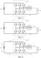
- a current flowing direction in the battery energy processing device at this time is shown in FIG. 4 In the process, the voltage across the energy storage element 40 continues to increase. However, the current flowing from the second end of the motor winding gradually decreases.
- the voltage across the energy storage element 40 reaches a maximum value.
- the energy storage element 40 automatically transforms from receiving energy from the motor winding 30 to releasing energy to the motor winding 30.
- the current flowing through the energy storage element 40 begins to reverse compared to the current flow direction as shown in FIG. 4 .
- a current flowing direction in the battery energy processing device at this time is switched to a direction shown in FIG. 5 . In the process, the voltage across the energy storage element 40 continuously decreases.
- the controller may control the upper bridge arm of the bridge arm converter 20 to be turned on and the lower bridge arm to be turned off.
- a current flow direction in the battery energy processing device at this time is shown in FIG. 6 .
- the battery 10 is in a charging state.
- the energy storage element 40 releases energy, and the voltage across the energy storage element continuously decreases.
- the current flowing through the energy storage element 40 also gradually decreases.
- the energy storage element 40 and the motor winding 30 automatically switch from releasing energy to the battery to receiving energy from the battery.
- the current flowing through the energy storage element 40 begins to reverse compared to the current flow direction as shown in FIG. 6 .
- a current flow direction in the battery energy processing device at this time changes back to the direction shown in FIG. 3 , and the battery 10 is discharged to the outside.
- the above four processes may be continuously cycled so that cyclic charging and discharging can be quickly performed between the energy storage element 40 and the battery 10.
- Internal resistance of the battery generates a large amount of heat, which causes a quick temperature rise of the battery, which improves the heating efficiency of the battery.
- the three-phase bridge arms are controlled in a same way, which allows for a current vector of 0 inside the motor, eliminates torque pulsation, and thereby guarantees driving safety and increases the service life of the motor.
- the controller 50 may keep the upper bridge arm off and the lower bridge arm on for a relatively long time in the process shown in FIG. 4 , so that the energy storage element 40 can automatically transform from receiving energy from the motor winding 30 to releasing energy to the motor winding 30, thereby completing switching from the process shown in FIG. 4 to a process shown in FIG. 5 .
- the controller 50 may keep the upper bridge arm on and the lower bridge arm off for a relatively long time in the process shown in FIG. 6 , so that the energy storage element 40 and the motor winding 30 can automatically are switched from releasing energy to the battery to receiving energy from the battery, thereby completing the switching from the process shown in FIG. 6 to the process shown in FIG. 3 .
- the controller 50 may be configured to: in the first preset state, acquire a current flowing through the energy storage element 40 and/or a voltage across the energy storage element 40, and control switching of the on/off of the upper bridge arm and the lower bridge arm of the bridge arm converter 20 according to the current and/or the voltage. In this way, the controller 50 may accurately determine a timing of switching the on/off of the upper bridge arm and the lower bridge arm according to the current flowing through the energy storage element 40 and/or the voltage across the energy storage element 40, so as to realize the switching from the process shown in FIG. 5 to the process shown in FIG. 6 and the switching from the process shown in FIG. 3 to the process shown in FIG. 4 , thereby realizing precise control.
- the controller 50 may be configured to control, in the first preset state,
- a current direction corresponding to the first current threshold is opposite to a current direction corresponding to the second current threshold.
- the first current threshold, the second current threshold, the first voltage threshold, and the second voltage threshold may be determined according to empirical data, or may be pre-calibrated according to experimental data, or may be determined according to a formula.
- the formula may represent a correspondence between each threshold and environmental information. When the environmental information changes, each threshold may be changed accordingly.
- the environmental information may include, for example, a battery service time, state of charge (SOH) information, a battery temperature, and an ambient temperature.
- SOH state of charge
- the above formula may be obtained by function fitting by using data in different experimental conditions.
- the energy storage element 40 and the motor winding 30 are switched from releasing energy to the battery to receiving energy from the battery according to a turn-on time of the upper bridge.
- the process shown in FIG. 6 switches to the process shown in FIG. 3 is realized.
- the energy storage element 40 is switched from receiving energy from the motor winding 30 to releasing energy to the motor winding 30 according to a turn-on time of the lower bridge arm.
- the process shown in FIG. 4 switches to the process shown in FIG. 5 is realized.
- the battery energy processing device may further include a switch K1 connected in series with the energy storage element 40.
- the switch K1 is connected between the second end of the motor winding 30 and the second bus terminal of the bridge arm converter 20.
- the controller 50 may be configured to control, in the first preset state, the first switch K1 to be turned on.
- the battery energy processing device may further include a switch K2 and a switch K3.
- the switch K2 is connected between the positive electrode of the battery 10 and the first bus terminal of the bridge arm converter 20.
- the switch K3 is connected between the negative electrode of the battery 10 and the second bus terminal of the bridge arm converter 20.
- the controller 50 may be configured to control, in the first preset state, the second switch K2 and the third switch K3 to be turned on.
- the controller 50 may control the bridge arm converter 20 to reduce charging and discharging currents of the battery 10 until the current value becomes zero, control the switches K2 and K3 to be off, and control the bridge arm converter 20 so that the energy storage element 40 is released. After the completion of the release of the energy storage element 40, the controller 50 controls the switch K1 to be off, so that the vehicle is restored to the parking state.
- the controller 50 may be further configured to: in a second preset state, control the first switch K1 to be turned off, and control the bridge arm converter 20 so that a motor corresponding to the motor winding 30 outputs power.
- the second preset state is a driving state of the vehicle. In the current driving condition, the switch K1 needs to be kept off, and the controller 50 controls the bridge arm converter 20 so that the motor corresponding to the motor winding 30 outputs power to realize a vehicle driving function.
- the switch K2 and the switch K3 are also kept on.
- the switch K1 can be used as a switch for switching between a battery heating state and the vehicle driving state.
- the arrangement of the switch K1 realizes the two functions, that is, the battery heating function and the vehicle driving function of the battery energy processing device provided in the present disclosure.
- By switching the on/off state of the switch K1 control the function of the battery energy processing device, so that the practicability of the battery energy processing device is further improved.
- the switch K1 in the second preset state, the switch K1 is in the off state, and the bridge arm controller 20 controls the motor through space vector pulse width modulation to drive the motor.
- the switch K1 When switching from the second preset state to the first preset state, the switch K1 is turned on to enter a battery heating process.
- the controller 50 controls the bridge arm controller 20 in the manner described above with reference to with FIG. 3 to FIG. 6 , so that cyclic charging and discharging can be quickly performed between the energy storage element 40 and the battery 10, thereby completing the battery heating process.
- the controller 50 may control the bridge arm converter 20 to reduce the charging and discharging currents of the battery 10, until the current value becomes zero, and then control the bridge arm converter 20 to complete the release of the energy storage element 40.
- the controller 50 controls the switch K1 to be turned off, so that the hardware circuit of the battery energy processing device is restored to the structure in the vehicle driving state. Then the controller 50 may control the motor through space vector pulse width modulation to drive the motor, so that the vehicle enters a travelling state.
- the above motor winding 30 may be a motor winding of the driving motor of the vehicle.
- the above bridge arm controller 20 may be a bridge arm controller of the driving motor. That is to say, in the battery energy processing device provided in the present disclosure, the driving motor of the vehicle is reused for battery heating. Since a power of the driving motor is relatively large, a corresponding heating power is relatively large during the heating, so that the heating rate can be increased and the heating efficiency can be improved.
- the energy storage element 40 may be a capacitor of a charging circuit of the vehicle.
- the capacitor is required to satisfy both the charging requirements and the heating requirements. Therefore, the energy storage element 40 also reuses the existing capacitor in the vehicle, so that an additional element is not required to be provided as the energy storage element 40, which can further improve the utilization of the devices in the vehicle, reduce the occupation of the vehicle space, and reduce the costs of the whole vehicle, thereby facilitating the promotion of new energy vehicles.
- the bridge arm controller of the driving motor, and the capacitor of the charging circuit can build the battery energy processing device to realize the heating of the battery.
- the switch K1 is required to be added to enable both the battery heating function and the vehicle driving function of the battery energy processing device, and the switching between the two states can be flexibly realized through control of the switch K1, which does not require arrangement of different hardware structures. Therefore, the utilization of the devices in the vehicle is improved, the occupation of the vehicle space is reduced, and the costs of the whole vehicle are reduced, thereby facilitating the promotion of new energy vehicles.
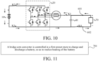
- the battery energy processing device two ends of the energy storage element 40 are connected with a first terminal 601 and a second terminal 602 for connecting to an external power supply device 70.
- the controller 50 may be further configured to control the bridge arm converter 20 in the third preset state, so that the power supply device 70 charges the battery through the battery energy processing device.
- the power supply device 70 may perform boost charge or direct charge the battery through the battery energy processing device or the battery.
- the battery energy processing device further includes a switch K1 and a switch K4.
- the switch K1 is respectively connected with the second end of the motor winding 30 and a first end of the energy storage element 40
- the first terminal 601 is respectively connected with the first end of the energy storage element 40 and the switch K1
- the switch K4 is respectively connected with a second end of the energy storage element 40 and the second bus terminal of the bridge arm controller 20
- the second terminal 602 is connected with the switch K4.
- the controller 50 may be configured to: in the third preset state, control the switch K1 and switch K4 to be turned on, and control the bridge arm converter 20,to charge the battery 10 by the power supply device 70.
- the battery energy processing device may further include a switch K2 and a switch K3. Therefore, in the third preset state, the controller 50 needs to control the switch K2 and the switch K3 to be turned on.
- the above third preset state is a battery charging state.
- the controller 50 may determine that currently the battery 10 needs to be charged through the power supply device 70.
- the controller 50 may control the switches K1, K2, K3, and K4 to be on, and control the on/off of the lower bridge arm of the bridge arm converter 20, so that the power supply device 70 performs the boost charging on the battery 10.
- the upper bridge arm and the lower bridge arm of the bridge arm converter 20 cannot be turned on simultaneously. 2. If one of the upper bridge arm and the lower bridge arm is turned on, the other is turned off. For example, if the upper bridge arm is turned on, the lower bridge arm is turned off, or if the upper bridge arm is turned off, the lower bridge arm is turned on. 3. If one of the upper bridge arm and the lower bridge arm is turned off, the other may be turned off or turned on. For example, if the upper bridge arm is turned off, the lower bridge arm may be turned off or turned on, or if the upper bridge arm is turned off, the upper bridge arm may be turned off or turned on.
- the controller 50 may control the lower bridge arm of the bridge arm converter 20 to be turned on and the upper bridge arm of the bridge arm converter to be turned off. At this time, a current flows from a positive electrode of the power supply device 70, passes through the motor winding and the lower bridge arm, and then flows to a negative electrode of the power supply device 70. The current increases continuously. As shown in FIG. 9 , the controller 50 may then control the lower bridge arm of the bridge arm converter 20 to be turned off and the upper bridge arm of the bridge arm converter to be turned on or off.
- a current flows from the positive electrode of the power supply device 70, passes through the motor winding and the upper bridge arm, and then flows to the positive electrode of the battery to charge the battery.
- a current from the negative electrode of the battery flows back to the negative electrode of the power supply device 70. It should be noted that, when the upper bridge arm is in the turn-off state, the current flows through a diode of the upper bridge arm.
- the energy storage function of the motor winding can realize the boost charging of the battery 10 by the power supply device 70.
- the third preset state above is the battery charging state.
- the controller 50 may determine that currently the battery 10 needs to be charged through the power supply device 70.
- the controller 50 may control the switches K1, K2, K3, and K4 to be turned on, and control the lower bridge arm of the bridge arm converter 20 to be turned off and the upper bridge arm of the bridge arm converter to be turned on or off.
- a current flows from the positive electrode of the power supply device 70, passes through the motor winding and the upper bridge arm, and then flows to the positive electrode of the battery to charge the battery. That is to say, the power supply device 70 directly charges the battery 10.
- the upper bridge arm is in the off state, the current flows through a diode of the upper bridge arm.
- the arrangement of the switch K1 and the switch K4 causes the battery energy processing device provided in the present disclosure to provide three different functions, that is, the battery heating function, the vehicle driving function, and the boost charging function based on the same hardware structure. Switching among the three states can be flexibly realized through the control of on/off state of the switches, which does not require arrangement of different hardware structures. Therefore, the utilization of the devices in the vehicle is improved, the occupation of the vehicle space is reduced, and the costs of the whole vehicle are reduced, thereby facilitating the promotion of new energy vehicles.
- the switching from the third preset state to the first preset state may alternatively be realized by turning off the switch K4. Then the controller 50 controls the bridge arm converter 20 to quickly perform cyclic charging and discharging between the energy storage element 40 and the battery 10, thereby completing the battery heating process.
- the voltage of the energy storage element 40 is required to be regulated to a preset value by controlling the bridge arm controller 20, and then the power supply device 70 is connected to the first terminal 601 and the second terminal 602 of the battery energy processing device to perform boost charging on the battery.
- the present disclosure further provides a vehicle, which includes a battery and the battery energy processing device in any of the above embodiments.
- the vehicle provided in the present disclosure includes the battery energy processing device in any of the above embodiments, and a new circuit topology connected with the battery 10 including the bridge arm converter 20, the motor winding 30, and the energy storage element 40 is designed.
- the energy storage element 40 is respectively connected with the second end of the motor winding 30 and the second bus terminal of the bridge arm converter 20, and the bridge arm converter 20 is respectively connected with the battery 10 and the motor winding 30.
- the bridge arm converter 20 is controlled in the first preset state to charge and discharge the battery 10, and internal resistance of the battery 10 causes the battery 10 to generate a large amount of heat, which causes a temperature rise of the battery 10, thereby realizing the heating of the battery 10.
- FIG. 11 is a flowchart of a battery energy processing method according to an exemplary embodiment of the present disclosure. As shown in FIG. 11 , the method may include the following steps:
- Abridge arm converter is controlled in a first preset state to charge and discharge a battery, so as to realize heating of the battery.
- a first bus terminal of the bridge arm converter 20 is connected with a positive electrode of the battery 10
- a second bus terminal of the bridge arm converter 20 is connected with a negative electrode of the battery 10
- a first end of a motor winding 30 is connected with a midpoint of the bridge arm converter 20
- an energy storage element 40 is respectively connected with a second end of the motor winding 30 and the second bus terminal of the bridge arm converter 20.
- a new circuit topology connected with the battery 10 including the bridge arm converter 20, the motor winding 30, and the energy storage element 40 is designed.
- the energy storage element 40 is respectively connected with the second end of the motor winding 30 and the second bus terminal of the bridge arm converter 20, and the bridge arm converter 20 is respectively connected with the battery 10 and the motor winding 30.
- the bridge arm converter 20 is controlled in the first preset state to charge and discharge the battery 10, and internal resistance of the battery 10 causes the battery 10 to generate a large amount of heat, which causes a temperature rise of the battery 10, thereby realizing the heating of the battery 10.
- bridge arm converter is controlled in the first preset state to charge and discharge the energy storage element and the battery.
- the energy storage element can store and release energy.
- the bridge arm converter may be controlled to control a direction of a current flowing through the motor winding and a voltage across the energy storage element.
- the charging and discharging between the energy storage element and the battery can be controlled. Due to the internal resistance of the battery, the charging and discharging between the energy storage element and the battery causes the battery to generate a large amount of heat, which causes a temperature rise of the battery, thereby realizing the heating of the battery.
- S701 may further include: controlling the bridge arm converter so that the energy storage element and the battery cyclically charges and discharges to realize the heating of the battery.
- the internal resistance of the battery causes the battery to generate a large amount, which causes a quick temperature rise of the battery, which improves the heating efficiency of the battery.
- S701 may further include: controlling at least one phase bridge arm of the bridge arm converter in the first preset state to charge and discharge the energy storage element and the battery.
- the battery energy processing method provided in the present disclosure can provide a variety of control policies for selection, that is, provide both a possibility of causing one phase winding to be involved in the energy exchange between the energy storage element and the battery and a possibility of causing the multi-phase windings to be involved in the energy exchange between the energy storage element and the battery.
- corresponding policies may be configured according to an actual heating demand, to realize different heating efficiency, which further enhances the flexibility and the practicability.
- upper bridge arms of the multi-phase bridge arms are simultaneously turned on, or lower bridge arms of the multi-phase bridge arms are simultaneously turned on.
- the multi-phase windings in the motor winding can be involved in the energy exchange between the energy storage element and the battery, and the capability to allow a current to pass through can be increased, so that the battery heating rate can be increased, and the heating efficiency of the battery can be improved.
- three-phase bridge arms in the bridge arm converter may be controlled in the above method, so that upper bridge arms of the three-phase bridge arms are simultaneously turned on or lower bridge arms of the three-phase bridge arms are simultaneously turned on.
- the three-phase bridge arms are controlled in a same way, which allows for a current vector of 0 inside the motor, eliminates torque pulsation, and thereby guarantees driving safety and increases the service life of the motor.
- the three-phase windings are jointly involved in the energy exchange between the energy storage element and the battery, so that the capability to allow a current to pass through is further increased, and the heating efficiency of the battery is further improved.
- the controlling at least one phase bridge arm of the bridge arm converter to charge and discharge the energy storage element and the battery includes: acquiring a current flowing the through the energy storage element and/or a voltage across the energy storage element, and controlling switching of on/off state of an upper bridge arm and a lower bridge arm of the bridge arm converter according to the current and/or the voltage.
- controlling switching of on/off state of an upper bridge arm and a lower bridge arm of the bridge arm converter according to the current and/or the voltage includes: controlling the upper bridge arm to be turned off and the lower bridge arm to be turned on when the upper bridge arm is in the turn-on state and the current increases to a first current threshold and/or the voltage increases to a first voltage threshold; and controlling the upper bridge arm to be turned on and the lower bridge arm to be turned off when the lower bridge arm is in the turn- on state and the current reaches a second current threshold and/or the voltage decreases to a second voltage threshold.
- a current direction corresponding to the first current threshold is opposite to a current direction corresponding to the second current threshold.
- a timing of switching of on/off state of the upper bridge arm and the lower bridge arm may be accurately determined according to the current flowing through the energy storage element and/or the voltage across the energy storage element, thereby realizing precise control.
- the energy storage element and the motor winding are switched from releasing energy to the battery to receiving energy from the battery according to a turn-on time of the upper bridge arm; and when the lower bridge arm is in the turn-on state, the energy storage element is switched from receiving energy from the motor winding to releasing energy to the motor winding according to a turn-on time of the lower bridge arm.
- the energy storage element is connected in series with a first switch K1, and the first switch K1 is connected between the second end of the motor winding and the second bus terminal of the bridge arm converter.
- the method may further include: controlling, in the first preset state, the first switch K1 to be turned on.
- the method may further include: in a second preset state, controlling the first switch K1 to be turned off, and controlling the bridge arm converter so that a motor corresponding to the motor winding outputs power.
- the first switch K1 can be used as a switch for switching between a battery heating state and a vehicle driving state.
- the arrangement of the switch K1 realizes the two functions, that is, the battery heating function and the vehicle driving function of the battery energy processing method provided in the present disclosure.
- By switching the on/off state of the switch K1 different function provided in the battery energy processing method is realized, so that the practicability is further improved.
- two ends of the energy storage element are connected with a first terminal and a second terminal for connecting to an external power supply device.
- the method may further include: controlling the bridge arm converter in a third preset state, so that the power supply device charges the battery through the motor winding.
- the power supply device performs boost charging on the battery through the motor winding. At this time, by periodically switching the on/off state of a lower bridge arm of the bridge arm converter in the third preset state, the power supply device performs the boost charging on the battery; or
- the power supply device directly charges the battery through the motor winding.
- the lower bridge arm of the bridge arm converter is controlled to be turned off in the third preset state, so that the power supply device directly charges the battery.
- the battery energy processing method provided in the present disclosure can provide three different functions, that is, the battery heating function, the vehicle driving function, and the boost charging function based on the same hardware structure.
- the switching among the three states can be flexibly realized through control of the on/off state of the switch, which does not require arrangement of different hardware structures. Therefore, the utilization of the devices in the vehicle is improved, the occupation of the vehicle space is reduced, and the costs of the whole vehicle are reduced, thereby facilitating the promotion of new energy vehicles.
Landscapes
- Engineering & Computer Science (AREA)
- Manufacturing & Machinery (AREA)
- General Chemical & Material Sciences (AREA)
- Electrochemistry (AREA)
- Chemical Kinetics & Catalysis (AREA)
- Chemical & Material Sciences (AREA)
- Power Engineering (AREA)
- Mechanical Engineering (AREA)
- Transportation (AREA)
- Automation & Control Theory (AREA)
- Life Sciences & Earth Sciences (AREA)
- Sustainable Energy (AREA)
- Sustainable Development (AREA)
- Charge And Discharge Circuits For Batteries Or The Like (AREA)
- Secondary Cells (AREA)
- Electric Propulsion And Braking For Vehicles (AREA)
- Inverter Devices (AREA)
Abstract
Description
- The present disclosure claims priority to
Chinese Patent Application 202010502048.8, filed on June 4, 2020 - The present disclosure relates to the technical field of batteries, and more specifically, to a battery energy processing device and method and a vehicle.
- With the wide use of new energy, batteries can be used as power sources in various fields. Performance of the battery varies with the different environment where the battery pack is used as a power source. For example, the performance of the battery in a low temperature environment is much lower than that in a normal temperature environment. For example, at a zero temperature, the discharge capacity of the battery decreases with the decrease of the temperature. At -30°C, the discharge capacity of the battery is substantially 0, resulting in a failure of the battery. In order to use the battery in the low temperature environment, the battery is required to be heated.
- The present disclosure aims to resolve at least one of the technical problems in the related art.
- A first objective of the present disclosure is to provide a battery energy processing device.
- A second objective of the present disclosure is to provide a battery energy processing method.
- A third objective of the present disclosure is to provide a vehicle.
- In order to achieve the above objectives, a first aspect of embodiments of the present disclosure provide a battery energy processing device. The battery energy processing device includes: a bridge arm converter, having a first bus terminal connected with a positive electrode of a battery and a second bus terminal connected with a negative electrode of the battery; a motor winding, having a first end connected with a midpoint of the bridge arm converter; an energy storage element, respectively connected with a second end of the motor winding and the second bus terminal; and a controller, configured to control the bridge arm converter to charge and discharge the battery, so as to realize heating of the battery in a first preset state.
- A second aspect of embodiments of the present disclosure provide a battery energy processing method. The battery energy processing method includes: controlling a bridge arm converter to charge and discharge a battery to realize heating of the battery in a first preset state, where a first bus terminal of the bridge arm converter is connected with a positive electrode of the battery; a second bus terminal of the bridge arm converter is connected with a negative electrode of the battery; a first end of a motor winding is connected with a midpoint of the bridge arm converter; and an energy storage element is respectively connected with a second end of the motor winding and the second bus terminal.
- A third aspect of the present disclosure provides a vehicle, which includes a battery and the battery energy processing device provided in the above first aspect.
- In the above technical solution, a new circuit topology which are connected with the battery including the bridge arm converter, the motor winding, and the energy storage element is designed. Specifically, the energy storage element is respectively connected with the second end of the motor winding and the second bus terminal of the bridge arm converter, and the bridge arm converter is respectively connected with the battery and the motor winding. Based on the circuit topology, the bridge arm converter is controlled in the first preset state to charge and discharge the battery, and internal resistance of the battery causes the battery to generate a large amount of heat, which causes a temperature rise of the battery, thereby realizing the heating of the battery.
- Other features and advantages of the present disclosure will be described in detail in the following detailed description part.
- The accompanying drawings are intended to provide further understanding of the present disclosure and constitute a part of this specification. The accompanying drawings and the specific implementations below are used together for explaining the present disclosure rather than constituting a limitation to the present disclosure. In the accompanying drawings,
-
FIG. 1 is a structural block diagram of a battery energy processing device according to an exemplary embodiment of the present disclosure. -
FIG. 2 is a circuit topology diagram of an exemplary embodiment of the battery energy processing device shown inFIG. 1 according to the present disclosure. -
FIG. 3 to FIG. 6 are schematic diagrams of cyclic charging and discharging processes of the battery energy processing device provided inFIG. 2 according to the present disclosure in a first preset state. -
FIG. 7 is a circuit topology diagram of another exemplary embodiment of the battery energy processing device shown inFIG. 2 according to the present disclosure. -
FIG. 8 and FIG. 9 are circuit topology diagrams of a battery energy processing device according to another exemplary embodiment of the present disclosure in a third preset state. -
FIG. 10 is a circuit topology diagram of a battery energy processing device according to still another exemplary embodiment of the present disclosure in a third preset state. -
FIG. 11 is a flowchart of a battery energy processing method according to an exemplary embodiment of the present disclosure. - Specific implementations of the present disclosure are described in detail below with reference to the accompanying drawings. It should be understood that the specific implementations described herein are merely used to describe and explain the present disclosure, but are not intended to limit the present disclosure.
- As shown in
FIG. 1 , a battery energy processing device includes: abridge arm converter 20, having a first bus terminal connected with a positive electrode of abattery 10 and a second bus terminal connected with a negative electrode of thebattery 10; a motor winding 30, having a first end connected with a midpoint of thebridge arm converter 20; anenergy storage element 40, respectively connected with a second end of the motor winding 30 and the second bus terminal; and acontroller 50, configured to control thebridge arm converter 20 to charge and discharge thebattery 10, so as to realize heating of thebattery 10 in a first preset state. - A new circuit topology which are connected with the
battery 10 including thebridge arm converter 20, the motor winding 30, and theenergy storage element 40 is designed. Specifically, theenergy storage element 40 is respectively connected with the second end of the motor winding 30 and the second bus terminal of thebridge arm converter 20, and thebridge arm converter 20 is respectively connected with thebattery 10 and the motor winding 30. Based on the circuit topology, thebridge arm converter 20 is controlled in the first preset state to charge and discharge thebattery 10, and internal resistance of thebattery 10 causes thebattery 10 to generate a large amount of heat, which causes a temperature rise of thebattery 10, thereby realizing the heating of thebattery 10. - In a specific embodiment, in the first preset state, the
controller 50 causes theenergy storage element 40 and thebattery 10 to charge and discharge. - The battery energy processing device may be configured in a vehicle. In this case, the
battery 10 may be a battery configured in a vehicle. Certainly, the battery energy processing device may alternatively be configured in other devices having batteries. This is not limited in the present disclosure. - In the battery energy processing device provided in the present disclosure, the motor winding 30 may include multi-phase windings, for example, two-phase windings or three-phase windings shown in
FIG. 2 . Correspondingly, thebridge arm converter 20 may include multi-phase bridge arms, which are in a one-to-one correspondence with the multi-phase windings. As shown inFIG. 2 , the motor winding 30 may include a phase A winding, a phase B winding, and a phase C winding. Each phase winding has a respective first end and a second end (in a plane direction shown inFIG. 2 , the first end is a left end, and the second end is a right end). The first end of the phase A winding, the first end of the phase B winding, and the first end of the phase C winding form the first end of the motor winding 30 for connecting the midpoint of thebridge arm converter 20. In addition, the second end of the phase A winding, the second end of the phase B winding, and the second end of the phase C winding are connected together to form the second end of the motor winding 30 for connecting theenergy storage element 40. - For example, the
energy storage element 40 may be a capacitor. The first preset state may be a battery heating state. For example, the user may trigger a vehicle to enter the battery heating state by triggering a battery heating switch according to actual needs. Alternatively, thecontroller 50 may acquire a signal representing a battery temperature, and determine that the vehicle enters the battery heating state when the battery temperature is less than or equal to a battery temperature threshold. In the first preset state, thecontroller 50 may control thebridge arm converter 20 to charge and discharge theenergy storage element 40 and thebattery 10, so as to realize the heating of thebattery 10. - In the above technical solution, the
energy storage element 40 can store and release energy. In the first preset state, thebridge arm converter 20 may be controlled to control a direction of a current flowing through the motor winding 30 and a voltage across theenergy storage element 40. In this way, the charging and discharging between theenergy storage element 40 and thebattery 10 can be controlled. Due to the internal resistance of the battery, the charging and discharging between theenergy storage element 40 and thebattery 10 causes the battery to generate a large amount of heat, which causes a temperature rise of the battery, thereby realizing the heating of the battery. In addition, since the motor winding 30 includes multi-phase bridge arms, and thebridge arm converter 20 includes multi-phase bridge arms, in the first preset state, the battery energy processing device provided in the present disclosure can provide a variety of control policies for selection, that is, provide both a possibility of causing one phase winding to be involved in the energy exchange between theenergy storage element 40 and thebattery 10 and a possibility of causing the multi-phase windings to be involved in the energy exchange between theenergy storage element 40 and thebattery 10. In this way, thecontroller 50 may be configured with corresponding policies according to an actual heating demand, to realize different heating efficiency, which further enhances the flexibility and the practicability. - In the present disclosure, the
controller 50 control at least one phase bridge arm of thebridge arm converter 20 in the first preset state, so that theenergy storage element 40 and thebattery 10 charge and discharge. That is to say, in an embodiment, thecontroller 50 may control one phase bridge arm of thebridge arm converter 20, such as a phase A bridge arm inFIG. 2 , so that a winding corresponding to the phase bridge arm (for example, the phase A winding inFIG. 2 ) is involved in the energy exchange between theenergy storage element 40 and thebattery 10, thereby realizing the charging and discharging of thebattery 10 and theenergy storage element 40. In another embodiment, thecontroller 50 may control multi-phase bridge arms in thebridge arm converter 20, such as a phase A bridge arm and a phase B bridge arm inFIG. 2 , so that windings corresponding to the two-phase bridge arms (for example, the phase A winding and the phase B winding inFIG. 2 ) are involved in the energy exchange between theenergy storage element 40 and thebattery 10, thereby realizing the charging and discharging of thebattery 10 and theenergy storage element 40. During the control of the multi-phase bridge arms of thebridge arm converter 20, upper bridge arms of the controlled multi-phase bridge arms are simultaneously turned on (in this state, lower bridge arms of the multi-phase bridge arms are simultaneously turned off), or the lower bridge arms of the controlled multi-phase bridge arms are simultaneously turned on (in this state, the upper bridge arms of the multi-phase bridge arms are simultaneously turned off). In this way, the multi-phase windings of the motor winding 30 can be involved in the energy exchange between theenergy storage element 40 and thebattery 10, and the capability to allow a current to pass through can be increased, so that the battery heating rate can be increased, and the battery heating efficiency can be improved. - When a current exists in three-phase windings of the motor, a current vector is formed, and a magnetic field is generated, which causes the motor rotor to output a pulsating torque, thus generating great impact on a life of the motor and the driving safety. In order to prevent the above problem, in the implementations of the present disclosure, the
controller 50 may control three-phase bridge arms in thebridge arm converter 20, so that upper bridge arms of the three-phase bridge arms are simultaneously turned on or lower bridge arms of the three-phase bridge arms are simultaneously turned on. The three-phase bridge arms are controlled in a same way, which allows for a current vector of 0 inside the motor, eliminates torque pulsation, and thereby guarantees driving safety and increases the service life of the motor. In addition, the three-phase windings are jointly involved in the energy exchange between theenergy storage element 40 and thebattery 10, which further increases the capability to allow a current to pass through, and further improves the heating efficiency of the battery. - A process and a principle of controlling the
bridge arm converter 20 by the controller so that charges and discharges theenergy storage element 40 and thebattery 10 to realize the heating thebattery 10 are described in detail below with reference toFIG. 3 to FIG. 6 . - Firstly, the
controller 50 may control the upper bridge arm of thebridge arm converter 20 to be turned on and the lower bridge arm to be turned off. A current flowing direction in the battery energy processing device at this time is shown inFIG. 3 In the process, thebattery 10 is discharged to the outside. As the upper bridge arm turn-on time increases, the voltage across theenergy storage element 40 increases continuously to realize energy storage. - Next, the
controller 50 may control the lower bridge arm of thebridge arm converter 20 to be turned on and the upper bridge arm to be turned off. A current flowing direction in the battery energy processing device at this time is shown inFIG. 4 In the process, the voltage across theenergy storage element 40 continues to increase. However, the current flowing from the second end of the motor winding gradually decreases. - When the current flowing from the second end of the motor winding drops to zero, the voltage across the
energy storage element 40 reaches a maximum value. At this time, theenergy storage element 40 automatically transforms from receiving energy from the motor winding 30 to releasing energy to the motor winding 30. The current flowing through theenergy storage element 40 begins to reverse compared to the current flow direction as shown inFIG. 4 . A current flowing direction in the battery energy processing device at this time is switched to a direction shown inFIG. 5 . In the process, the voltage across theenergy storage element 40 continuously decreases. - Then, the controller may control the upper bridge arm of the
bridge arm converter 20 to be turned on and the lower bridge arm to be turned off. A current flow direction in the battery energy processing device at this time is shown inFIG. 6 . In the process, thebattery 10 is in a charging state. Theenergy storage element 40 releases energy, and the voltage across the energy storage element continuously decreases. The current flowing through theenergy storage element 40 also gradually decreases. - As the voltage across the
energy storage element 40 continuously decreases and the current flowing through theenergy storage element 40 continuously decreases, theenergy storage element 40 and the motor winding 30 automatically switch from releasing energy to the battery to receiving energy from the battery. The current flowing through theenergy storage element 40 begins to reverse compared to the current flow direction as shown inFIG. 6 . A current flow direction in the battery energy processing device at this time changes back to the direction shown inFIG. 3 , and thebattery 10 is discharged to the outside. - The above four processes may be continuously cycled so that cyclic charging and discharging can be quickly performed between the
energy storage element 40 and thebattery 10. Internal resistance of the battery generates a large amount of heat, which causes a quick temperature rise of the battery, which improves the heating efficiency of the battery. In addition, the three-phase bridge arms are controlled in a same way, which allows for a current vector of 0 inside the motor, eliminates torque pulsation, and thereby guarantees driving safety and increases the service life of the motor. - As shown in the above, in the process shown in
FIG. 3 , if the controlbridge arm converter 20 is controlled to be switched from the state in which the upper bridge arm is on and the lower bridge arm is off to the state in which the upper bridge arm is off and the lower bridge arm is on, a working state of the battery energy processing device is switched to a process shown inFIG. 4 . Then, before theenergy storage element 40 automatically transforms from receiving energy from the motor winding 30 to releasing energy to the motor winding 30, by turning on the upper bridge arm and turning off the lower bridge arm again, the working state of the battery energy processing device can be switched from the process shown inFIG. 4 to the process shown inFIG. 3 again, thereby realizing cyclic switching between the process shown inFIG. 3 and the process shown inFIG. 4 . After the two processes are cycled several times (a number of cycles may be preset), thecontroller 50 may keep the upper bridge arm off and the lower bridge arm on for a relatively long time in the process shown inFIG. 4 , so that theenergy storage element 40 can automatically transform from receiving energy from the motor winding 30 to releasing energy to the motor winding 30, thereby completing switching from the process shown inFIG. 4 to a process shown inFIG. 5 . - In addition, as shown in the above, in the process shown in
FIG. 5 , if the controlbridge arm converter 20 is controlled to be switched from the state in which the upper bridge arm is off and the lower bridge arm is on to the state in which the upper bridge arm is on and the lower bridge arm is off, the working state of the battery energy processing device is switched to a process shown inFIG. 6 . Then, before theenergy storage element 40 and the motor winding 30 switches from releasing energy to the battery to receiving energy from the battery, by turning off the upper bridge arm and turning on the lower bridge arm again, the working state of the battery energy processing device is switched from the process shown inFIG. 6 to the process shown inFIG. 5 again, thereby realizing cyclic switching between the process shown inFIG. 5 and the process shown inFIG. 6 . After the two processes are cycled several times (a number of cycles may be preset), thecontroller 50 may keep the upper bridge arm on and the lower bridge arm off for a relatively long time in the process shown inFIG. 6 , so that theenergy storage element 40 and the motor winding 30 can automatically are switched from releasing energy to the battery to receiving energy from the battery, thereby completing the switching from the process shown inFIG. 6 to the process shown inFIG. 3 . - In the present disclosure, the
controller 50 may be configured to: in the first preset state, acquire a current flowing through theenergy storage element 40 and/or a voltage across theenergy storage element 40, and control switching of the on/off of the upper bridge arm and the lower bridge arm of thebridge arm converter 20 according to the current and/or the voltage. In this way, thecontroller 50 may accurately determine a timing of switching the on/off of the upper bridge arm and the lower bridge arm according to the current flowing through theenergy storage element 40 and/or the voltage across theenergy storage element 40, so as to realize the switching from the process shown inFIG. 5 to the process shown inFIG. 6 and the switching from the process shown inFIG. 3 to the process shown inFIG. 4 , thereby realizing precise control. - Exemplarily, the
controller 50 may be configured to control, in the first preset state, - the upper bridge arm to be turned off and the lower bridge arm to be turned on when the upper bridge arm is in the turn-on state and the current flowing through the
energy storage element 40 reaches to a first current threshold and/or the voltage across theenergy storage element 40 increases to a first voltage threshold, for example, the switching from the process shown inFIG. 3 to the process shown inFIG. 4 ; and - the upper bridge arm to be turned on and the lower bridge arm is controlled to be turned off when the lower bridge arm is in the turn-on state and the current flowing through the
energy storage element 40 reaches to a second current threshold and/or the voltage across theenergy storage element 40 decreases to a second voltage threshold, for example, the switching from the process shown inFIG. 5 to the process shown inFIG. 6 . - A current direction corresponding to the first current threshold is opposite to a current direction corresponding to the second current threshold. It is worth noting that the first current threshold, the second current threshold, the first voltage threshold, and the second voltage threshold may be determined according to empirical data, or may be pre-calibrated according to experimental data, or may be determined according to a formula. The formula may represent a correspondence between each threshold and environmental information. When the environmental information changes, each threshold may be changed accordingly. The environmental information may include, for example, a battery service time, state of charge (SOH) information, a battery temperature, and an ambient temperature. The above formula may be obtained by function fitting by using data in different experimental conditions.
- Moreover, when the upper bridge arm is in the turn-on state, the
energy storage element 40 and the motor winding 30 are switched from releasing energy to the battery to receiving energy from the battery according to a turn-on time of the upper bridge. For example, the process shown inFIG. 6 switches to the process shown inFIG. 3 is realized. - When the lower bridge arm is in the turn-on state, the
energy storage element 40 is switched from receiving energy from the motor winding 30 to releasing energy to the motor winding 30 according to a turn-on time of the lower bridge arm. For example, the process shown inFIG. 4 switches to the process shown inFIG. 5 is realized. - As shown in
FIG. 7 , the battery energy processing device may further include a switch K1 connected in series with theenergy storage element 40. The switch K1 is connected between the second end of the motor winding 30 and the second bus terminal of thebridge arm converter 20. Thecontroller 50 may be configured to control, in the first preset state, the first switch K1 to be turned on. - In addition, the battery energy processing device may further include a switch K2 and a switch K3. The switch K2 is connected between the positive electrode of the
battery 10 and the first bus terminal of thebridge arm converter 20. The switch K3 is connected between the negative electrode of thebattery 10 and the second bus terminal of thebridge arm converter 20. Thecontroller 50 may be configured to control, in the first preset state, the second switch K2 and the third switch K3 to be turned on. - When the heating of the battery is completed, for example, users turn off the battery heating switch or the battery temperature satisfies a temperature threshold condition indicating that the heating of the battery may be stopped, to restore the vehicle to a parking state, the
controller 50 may control thebridge arm converter 20 to reduce charging and discharging currents of thebattery 10 until the current value becomes zero, control the switches K2 and K3 to be off, and control thebridge arm converter 20 so that theenergy storage element 40 is released. After the completion of the release of theenergy storage element 40, thecontroller 50 controls the switch K1 to be off, so that the vehicle is restored to the parking state. - Optionally, the
controller 50 may be further configured to: in a second preset state, control the first switch K1 to be turned off, and control thebridge arm converter 20 so that a motor corresponding to the motor winding 30 outputs power. The second preset state is a driving state of the vehicle. In the current driving condition, the switch K1 needs to be kept off, and thecontroller 50 controls thebridge arm converter 20 so that the motor corresponding to the motor winding 30 outputs power to realize a vehicle driving function. In addition, in the second preset state, the switch K2 and the switch K3 are also kept on. - In this way, the switch K1 can be used as a switch for switching between a battery heating state and the vehicle driving state. The arrangement of the switch K1 realizes the two functions, that is, the battery heating function and the vehicle driving function of the battery energy processing device provided in the present disclosure. By switching the on/off state of the switch K1, control the function of the battery energy processing device, so that the practicability of the battery energy processing device is further improved.
- Specifically, in the second preset state, the switch K1 is in the off state, and the
bridge arm controller 20 controls the motor through space vector pulse width modulation to drive the motor. When switching from the second preset state to the first preset state, the switch K1 is turned on to enter a battery heating process. Thecontroller 50 controls thebridge arm controller 20 in the manner described above with reference to withFIG. 3 to FIG. 6 , so that cyclic charging and discharging can be quickly performed between theenergy storage element 40 and thebattery 10, thereby completing the battery heating process. - When switching from the first preset state to the second preset state, the
controller 50 may control thebridge arm converter 20 to reduce the charging and discharging currents of thebattery 10, until the current value becomes zero, and then control thebridge arm converter 20 to complete the release of theenergy storage element 40. After the completion of the release of theenergy storage element 40, thecontroller 50 controls the switch K1 to be turned off, so that the hardware circuit of the battery energy processing device is restored to the structure in the vehicle driving state. Then thecontroller 50 may control the motor through space vector pulse width modulation to drive the motor, so that the vehicle enters a travelling state. - In addition, in an embodiment of the present disclosure, the above motor winding 30 may be a motor winding of the driving motor of the vehicle. Correspondingly, the above
bridge arm controller 20 may be a bridge arm controller of the driving motor. That is to say, in the battery energy processing device provided in the present disclosure, the driving motor of the vehicle is reused for battery heating. Since a power of the driving motor is relatively large, a corresponding heating power is relatively large during the heating, so that the heating rate can be increased and the heating efficiency can be improved. In addition, since the existing driving motor on the vehicle is reused, an additional special motor is not required, which can improve the utilization of the devices in the vehicle, reduce the occupation of a vehicle space, reduce the weight of the vehicle, and reduce the costs of the whole vehicle, thereby facilitating the promotion of new energy vehicles. - Optionally, the
energy storage element 40 may be a capacitor of a charging circuit of the vehicle. The capacitor is required to satisfy both the charging requirements and the heating requirements. Therefore, theenergy storage element 40 also reuses the existing capacitor in the vehicle, so that an additional element is not required to be provided as theenergy storage element 40, which can further improve the utilization of the devices in the vehicle, reduce the occupation of the vehicle space, and reduce the costs of the whole vehicle, thereby facilitating the promotion of new energy vehicles. - In addition, reusing the driving motor of the vehicle, the bridge arm controller of the driving motor, and the capacitor of the charging circuit can build the battery energy processing device to realize the heating of the battery. Moreover, only the switch K1 is required to be added to enable both the battery heating function and the vehicle driving function of the battery energy processing device, and the switching between the two states can be flexibly realized through control of the switch K1, which does not require arrangement of different hardware structures. Therefore, the utilization of the devices in the vehicle is improved, the occupation of the vehicle space is reduced, and the costs of the whole vehicle are reduced, thereby facilitating the promotion of new energy vehicles.
- As shown in
FIG. 8, FIG. 9 , andFIG. 10 , in the battery energy processing device, two ends of theenergy storage element 40 are connected with afirst terminal 601 and asecond terminal 602 for connecting to an externalpower supply device 70. Thecontroller 50 may be further configured to control thebridge arm converter 20 in the third preset state, so that thepower supply device 70 charges the battery through the battery energy processing device. Specifically, thepower supply device 70 may perform boost charge or direct charge the battery through the battery energy processing device or the battery. - Specifically, the battery energy processing device further includes a switch K1 and a switch K4. As shown in
FIG. 8 and FIG. 9 , the switch K1 is respectively connected with the second end of the motor winding 30 and a first end of theenergy storage element 40, thefirst terminal 601 is respectively connected with the first end of theenergy storage element 40 and the switch K1, the switch K4 is respectively connected with a second end of theenergy storage element 40 and the second bus terminal of thebridge arm controller 20, and thesecond terminal 602 is connected with the switch K4. Thecontroller 50 may be configured to: in the third preset state, control the switch K1 and switch K4 to be turned on, and control thebridge arm converter 20,to charge thebattery 10 by thepower supply device 70. - The battery energy processing device may further include a switch K2 and a switch K3. Therefore, in the third preset state, the
controller 50 needs to control the switch K2 and the switch K3 to be turned on. - As shown in
FIG. 8 and FIG. 9 , the above third preset state is a battery charging state. When thefirst terminal 601 and thesecond terminal 602 are connected with the external power supply device 70 (for example, a charging pile), thecontroller 50 may determine that currently thebattery 10 needs to be charged through thepower supply device 70. At this time, thecontroller 50 may control the switches K1, K2, K3, and K4 to be on, and control the on/off of the lower bridge arm of thebridge arm converter 20, so that thepower supply device 70 performs the boost charging on thebattery 10. - Those of ordinary skill in the art know the following: 1. The upper bridge arm and the lower bridge arm of the
bridge arm converter 20 cannot be turned on simultaneously. 2. If one of the upper bridge arm and the lower bridge arm is turned on, the other is turned off. For example, if the upper bridge arm is turned on, the lower bridge arm is turned off, or if the upper bridge arm is turned off, the lower bridge arm is turned on. 3. If one of the upper bridge arm and the lower bridge arm is turned off, the other may be turned off or turned on. For example, if the upper bridge arm is turned off, the lower bridge arm may be turned off or turned on, or if the upper bridge arm is turned off, the upper bridge arm may be turned off or turned on. - For example, as shown in
FIG. 8 , in the third preset state, thecontroller 50 may control the lower bridge arm of thebridge arm converter 20 to be turned on and the upper bridge arm of the bridge arm converter to be turned off. At this time, a current flows from a positive electrode of thepower supply device 70, passes through the motor winding and the lower bridge arm, and then flows to a negative electrode of thepower supply device 70. The current increases continuously. As shown inFIG. 9 , thecontroller 50 may then control the lower bridge arm of thebridge arm converter 20 to be turned off and the upper bridge arm of the bridge arm converter to be turned on or off. At this time, a current flows from the positive electrode of thepower supply device 70, passes through the motor winding and the upper bridge arm, and then flows to the positive electrode of the battery to charge the battery. A current from the negative electrode of the battery flows back to the negative electrode of thepower supply device 70. It should be noted that, when the upper bridge arm is in the turn-off state, the current flows through a diode of the upper bridge arm. The energy storage function of the motor winding can realize the boost charging of thebattery 10 by thepower supply device 70. - As shown in
FIG. 10 , the third preset state above is the battery charging state. When thefirst terminal 601 and thesecond terminal 602 are connected with the externalpower supply device 70, for example, a charging pile, thecontroller 50 may determine that currently thebattery 10 needs to be charged through thepower supply device 70. At this time, thecontroller 50 may control the switches K1, K2, K3, and K4 to be turned on, and control the lower bridge arm of thebridge arm converter 20 to be turned off and the upper bridge arm of the bridge arm converter to be turned on or off. At this time, a current flows from the positive electrode of thepower supply device 70, passes through the motor winding and the upper bridge arm, and then flows to the positive electrode of the battery to charge the battery. That is to say, thepower supply device 70 directly charges thebattery 10. It should be noted that, when the upper bridge arm is in the off state, the current flows through a diode of the upper bridge arm. - The arrangement of the switch K1 and the switch K4 causes the battery energy processing device provided in the present disclosure to provide three different functions, that is, the battery heating function, the vehicle driving function, and the boost charging function based on the same hardware structure. Switching among the three states can be flexibly realized through the control of on/off state of the switches, which does not require arrangement of different hardware structures. Therefore, the utilization of the devices in the vehicle is improved, the occupation of the vehicle space is reduced, and the costs of the whole vehicle are reduced, thereby facilitating the promotion of new energy vehicles.
- When switching from the third preset state to the first preset state, after the completion of the charging process, by disconnecting the
power supply device 70 from thefirst terminal 601 and thesecond terminal 602 of the battery energy processing device through hardware the switching is completed. The switching from the third preset state to the first preset state may alternatively be realized by turning off the switch K4. Then thecontroller 50 controls thebridge arm converter 20 to quickly perform cyclic charging and discharging between theenergy storage element 40 and thebattery 10, thereby completing the battery heating process. - When switching from the first preset state to the third preset state, since the voltage across the
energy storage element 40 is a variable, the voltage of theenergy storage element 40 is required to be regulated to a preset value by controlling thebridge arm controller 20, and then thepower supply device 70 is connected to thefirst terminal 601 and thesecond terminal 602 of the battery energy processing device to perform boost charging on the battery. - The present disclosure further provides a vehicle, which includes a battery and the battery energy processing device in any of the above embodiments.
- The vehicle provided in the present disclosure includes the battery energy processing device in any of the above embodiments, and a new circuit topology connected with the
battery 10 including thebridge arm converter 20, the motor winding 30, and theenergy storage element 40 is designed. Specifically, theenergy storage element 40 is respectively connected with the second end of the motor winding 30 and the second bus terminal of thebridge arm converter 20, and thebridge arm converter 20 is respectively connected with thebattery 10 and the motor winding 30. Based on the circuit topology, thebridge arm converter 20 is controlled in the first preset state to charge and discharge thebattery 10, and internal resistance of thebattery 10 causes thebattery 10 to generate a large amount of heat, which causes a temperature rise of thebattery 10, thereby realizing the heating of thebattery 10. - The present disclosure further provides a battery energy processing method.
FIG. 11 is a flowchart of a battery energy processing method according to an exemplary embodiment of the present disclosure. As shown inFIG. 11 , the method may include the following steps: - S701: Abridge arm converter is controlled in a first preset state to charge and discharge a battery, so as to realize heating of the battery. As shown in
FIG. 1 , a first bus terminal of thebridge arm converter 20 is connected with a positive electrode of thebattery 10, a second bus terminal of thebridge arm converter 20 is connected with a negative electrode of thebattery 10, a first end of a motor winding 30 is connected with a midpoint of thebridge arm converter 20, and anenergy storage element 40 is respectively connected with a second end of the motor winding 30 and the second bus terminal of thebridge arm converter 20. - A new circuit topology connected with the
battery 10 including thebridge arm converter 20, the motor winding 30, and theenergy storage element 40 is designed. Specifically, theenergy storage element 40 is respectively connected with the second end of the motor winding 30 and the second bus terminal of thebridge arm converter 20, and thebridge arm converter 20 is respectively connected with thebattery 10 and the motor winding 30. Based on the circuit topology, thebridge arm converter 20 is controlled in the first preset state to charge and discharge thebattery 10, and internal resistance of thebattery 10 causes thebattery 10 to generate a large amount of heat, which causes a temperature rise of thebattery 10, thereby realizing the heating of thebattery 10. - In a specific embodiment of the bridge arm converter is controlled in the first preset state to charge and discharge the energy storage element and the battery.
- In the above technical solution, the energy storage element can store and release energy. In the first preset state, the bridge arm converter may be controlled to control a direction of a current flowing through the motor winding and a voltage across the energy storage element. In this way, the charging and discharging between the energy storage element and the battery can be controlled. Due to the internal resistance of the battery, the charging and discharging between the energy storage element and the battery causes the battery to generate a large amount of heat, which causes a temperature rise of the battery, thereby realizing the heating of the battery.
- In an optional implementation, S701 may further include: controlling the bridge arm converter so that the energy storage element and the battery cyclically charges and discharges to realize the heating of the battery.
- During the cyclic charging and discharging between the energy storage element and the battery, the internal resistance of the battery causes the battery to generate a large amount, which causes a quick temperature rise of the battery, which improves the heating efficiency of the battery.
- In an optional implementation, S701 may further include: controlling at least one phase bridge arm of the bridge arm converter in the first preset state to charge and discharge the energy storage element and the battery.
- In this way, in the first preset state, the battery energy processing method provided in the present disclosure can provide a variety of control policies for selection, that is, provide both a possibility of causing one phase winding to be involved in the energy exchange between the energy storage element and the battery and a possibility of causing the multi-phase windings to be involved in the energy exchange between the energy storage element and the battery. In this way, corresponding policies may be configured according to an actual heating demand, to realize different heating efficiency, which further enhances the flexibility and the practicability.
- In an optional implementation, during control of multi-phase bridge arms of the bridge arm converter, upper bridge arms of the multi-phase bridge arms are simultaneously turned on, or lower bridge arms of the multi-phase bridge arms are simultaneously turned on.
- In this way, the multi-phase windings in the motor winding can be involved in the energy exchange between the energy storage element and the battery, and the capability to allow a current to pass through can be increased, so that the battery heating rate can be increased, and the heating efficiency of the battery can be improved.
- When a current exists in three-phase windings of the motor, a current vector is formed, and a magnetic field is generated, which causes the motor rotor to output a pulsating torque, thus generating great impact on the life of the motor and the driving safety. In order to prevent the above problem, in the implementations of the present disclosure, three-phase bridge arms in the bridge arm converter may be controlled in the above method, so that upper bridge arms of the three-phase bridge arms are simultaneously turned on or lower bridge arms of the three-phase bridge arms are simultaneously turned on. The three-phase bridge arms are controlled in a same way, which allows for a current vector of 0 inside the motor, eliminates torque pulsation, and thereby guarantees driving safety and increases the service life of the motor. In addition, the three-phase windings are jointly involved in the energy exchange between the energy storage element and the battery, so that the capability to allow a current to pass through is further increased, and the heating efficiency of the battery is further improved.
- In an optional implementation, the controlling at least one phase bridge arm of the bridge arm converter to charge and discharge the energy storage element and the battery includes: acquiring a current flowing the through the energy storage element and/or a voltage across the energy storage element, and controlling switching of on/off state of an upper bridge arm and a lower bridge arm of the bridge arm converter according to the current and/or the voltage.
- In an optional implementation, the controlling switching of on/off state of an upper bridge arm and a lower bridge arm of the bridge arm converter according to the current and/or the voltage includes: controlling the upper bridge arm to be turned off and the lower bridge arm to be turned on when the upper bridge arm is in the turn-on state and the current increases to a first current threshold and/or the voltage increases to a first voltage threshold; and controlling the upper bridge arm to be turned on and the lower bridge arm to be turned off when the lower bridge arm is in the turn- on state and the current reaches a second current threshold and/or the voltage decreases to a second voltage threshold. A current direction corresponding to the first current threshold is opposite to a current direction corresponding to the second current threshold.
- In this way, a timing of switching of on/off state of the upper bridge arm and the lower bridge arm may be accurately determined according to the current flowing through the energy storage element and/or the voltage across the energy storage element, thereby realizing precise control.
- In an optional implementation, when the upper bridge arm is in the turn-on state, the energy storage element and the motor winding are switched from releasing energy to the battery to receiving energy from the battery according to a turn-on time of the upper bridge arm; and when the lower bridge arm is in the turn-on state, the energy storage element is switched from receiving energy from the motor winding to releasing energy to the motor winding according to a turn-on time of the lower bridge arm.
- In an optional implementation, the energy storage element is connected in series with a first switch K1, and the first switch K1 is connected between the second end of the motor winding and the second bus terminal of the bridge arm converter. The method may further include: controlling, in the first preset state, the first switch K1 to be turned on.
- In an optional implementation, the method may further include: in a second preset state, controlling the first switch K1 to be turned off, and controlling the bridge arm converter so that a motor corresponding to the motor winding outputs power.
- In this way, the first switch K1 can be used as a switch for switching between a battery heating state and a vehicle driving state. The arrangement of the switch K1 realizes the two functions, that is, the battery heating function and the vehicle driving function of the battery energy processing method provided in the present disclosure. By switching the on/off state of the switch K1, different function provided in the battery energy processing method is realized, so that the practicability is further improved.
- In an optional implementation, two ends of the energy storage element are connected with a first terminal and a second terminal for connecting to an external power supply device. The method may further include: controlling the bridge arm converter in a third preset state, so that the power supply device charges the battery through the motor winding.
- Specifically, the power supply device performs boost charging on the battery through the motor winding. At this time, by periodically switching the on/off state of a lower bridge arm of the bridge arm converter in the third preset state, the power supply device performs the boost charging on the battery; or
- In another specific embodiment, the power supply device directly charges the battery through the motor winding. At this time, the lower bridge arm of the bridge arm converter is controlled to be turned off in the third preset state, so that the power supply device directly charges the battery.
- In this way, the battery energy processing method provided in the present disclosure can provide three different functions, that is, the battery heating function, the vehicle driving function, and the boost charging function based on the same hardware structure. The switching among the three states can be flexibly realized through control of the on/off state of the switch, which does not require arrangement of different hardware structures. Therefore, the utilization of the devices in the vehicle is improved, the occupation of the vehicle space is reduced, and the costs of the whole vehicle are reduced, thereby facilitating the promotion of new energy vehicles.
- For the method in the foregoing embodiments, a specific manner in which steps are already described in detail in the embodiments related to the method, and details are not described herein again.
- The specific implementations of the present disclosure are described above in detail with reference to the accompanying drawings, but the present disclosure is not limited to the specific details in the above implementations. Various simple variations may be made to the technical solutions of the present disclosure within the scope of the technical idea of the present disclosure, and such simple variations shall all fall within the protection scope of the present disclosure.
- It should be additionally noted that, the specific technical features described in the foregoing specific implementations may be combined in any proper manner in a case without conflict. To avoid unnecessary repetition, various possible combination manners are not described in the present disclosure.
- In addition, different implementations of the present disclosure may also be arbitrarily combined without departing from the idea of the present disclosure, and these combinations shall still be regarded as content disclosed in the present disclosure.
Claims (20)
- A battery energy processing device, comprising:a bridge arm converter, having a first bus terminal connected with a positive electrode of a battery and a second bus terminal connected with a negative electrode of the battery;a motor winding, having a first end connected with a midpoint of the bridge arm converter;an energy storage element, respectively connected with a second end of the motor winding and the second bus terminal; andcontroller, configured to control, in a first preset state, the bridge arm converter to charge and discharge the battery to realize heating of the battery.
- The battery energy processing device according to claim 1, wherein the controller controls at least one phase bridge arm of the bridge arm converter in the first preset state, so that the energy storage element charges and discharges the battery.
- The battery energy processing device according to claim 2, wherein during control of multi-phase bridge arms of the bridge arm converter, upper bridge arms of the multi-phase bridge arms are simultaneously on; or lower bridge arms of the multi-phase bridge arms are simultaneously on.
- The battery energy processing device according to claim 3, wherein the controller is configured to: in the first preset state, acquire a current flowing through the energy storage element and/or a voltage across the energy storage element, and control switching of on/off state of the upper bridge arms and the lower bridge arms of the bridge arm converter according to the current and/or the voltage.
- The battery energy processing device according to claim 4, wherein the controller is configured to: in the first preset state,control the upper bridge arms to be turned off and the lower bridge arms to be turned on when the upper bridge arms are in the on state and the current increases to a first current threshold and/or the voltage increases to a first voltage threshold; andcontrol the upper bridge arms to be turned on and the lower bridge arms to be turned off when the lower bridge arms are in the turn-on state and the current reaches a second current threshold and/or the voltage decreases to a second voltage threshold, whereina current direction corresponding to the first current threshold is opposite to a current direction corresponding to the second current threshold.
- The battery energy processing device according to claim 5, wherein when the upper bridge arms are in the turn-on state, the energy storage element and the motor winding are switched from releasing energy to the battery to receiving energy from the battery according to a turn-on time of the upper bridge arms; and
when the lower bridge arms are in the turn-on state, the energy storage element is switched from receiving energy from the motor winding to releasing energy to the motor winding according to a turn-on time of the lower bridge arms. - The battery energy processing device according to claim 1, further comprising a first switch connected in series with the energy storage element, wherein the first switch is connected between the second end of the motor winding and the second bus terminal; and
the controller is configured to control, in the first preset state, the first switch to be turned on. - The battery energy processing device according to claim 7,
wherein the controller is further configured to: in a second preset state, control the first switch to be turned off, and control the bridge arm converter so that a motor corresponding to the motor winding outputs power. - The battery energy processing device according to claim 1, wherein two ends of the energy storage element are connected with a first terminal and a second terminal for connecting to an external power supply device; and the controller is further configured to: in a third preset state, control the bridge arm converter, so that the power supply device charges the battery through the battery energy processing device.
- The battery energy processing device according to claim 9, further comprising a first switch and a second switch, wherein the first switch is respectively connected with the second end of the motor winding and the energy storage element; the first terminal is respectively connected with the energy storage element and the first switch; the second switch is respectively connected with the energy storage element and the second bus terminal; the second terminal is connected with the second switch; and
the controller is configured to: in the third preset state, control the first switch and the second switch to be turned-on, and control the bridge arm converter so that the power supply device charges the battery. - The battery energy processing device according to claim 10, wherein the controller is configured to: in the third preset state, control the first switch and the second switch to be turned-on, and control the lower bridge arms of the bridge arm converter to be on and off periodically, so that the power supply device performs boost charging on the battery; or
the controller is configured to: in the third preset state, control the first switch and the second switch to be turned-on, and control the lower bridge arms of the bridge arm converter to be turned-off, so that the power supply device directly charges the battery. - The battery energy processing device according to any of claims 1 to 11, wherein the controller is configured to: in the first preset state, control the bridge arm converter so that the energy storage element and the battery cyclically charges and discharges to realize heating of the battery.
- A battery energy processing method, comprising:
controlling, in a first preset state, a bridge arm converter to charge and discharge a battery to realize heating of the battery, wherein a first bus terminal of the bridge arm converter is connected with a positive electrode of the battery; a second bus terminal of the bridge arm converter is connected with a negative electrode of the battery; a first end of a motor winding is connected with a midpoint of the bridge arm converter; and an energy storage element is respectively connected with a second end of the motor winding and the second bus terminal. - The method according to claim 13, comprising: controlling the bridge arm converter in the first preset state to charge and discharge the energy storage element and the battery.
- The method according to claim 14, wherein the controlling the bridge arm converter to charge and discharge the energy storage element and the battery comprises:controlling at least one phase bridge arm of the bridge arm converter in the first preset state, to charge and discharge the energy storage element and the battery, comprising: in the first preset state, acquiring a current flowing through the energy storage element and/or a voltage across the energy storage element, and controlling switching of on/off state of an upper bridge arm and a lower bridge arm of the bridge arm converter based on the current and/or the voltage, whereinduring control of multi-phase bridge arms of the bridge arm converter, upper bridge arms of the multi-phase bridge arms are simultaneously turned on; or lower bridge arms of the multi-phase bridge arms are simultaneously turned on.
- The method according to claim 15, wherein the controlling switching of on/off state of an upper bridge arm and a lower bridge arm of the bridge arm converter based on the current and/or the voltage comprises:controlling the upper bridge arm to be turned off and the lower bridge arm to be turned on when the upper bridge arm is in the turn-on state and the current increases to a first current threshold and/or the voltage increases to a first voltage threshold; andcontrolling the upper bridge arm to be turned on and the lower bridge arm to be turned off when the lower bridge arm is in the turn-on state and the current reaches a second current threshold and/or the voltage decreases to a second voltage threshold, whereina current direction corresponding to the first current threshold is opposite to a current direction corresponding to the second current threshold;when the upper bridge arm is in the turn-on state, the energy storage element and the motor winding are switched from releasing energy to the battery to receiving energy from the battery according to a turn-on time of the upper bridge arm; andwhen the lower bridge arm is in the turn-on state, the energy storage element is switched from receiving energy from the motor winding to releasing energy to the motor winding according to a turn-on time of the lower bridge arm.
- The method according to claim 13, wherein the energy storage element is connected in series with a first switch; the first switch is connected between the second end of the motor winding and the second bus terminal; andthe method further comprises: controlling, in the first preset state, the first switch to be turned on; andin a second preset state, controlling the first switch to be turned on, and controlling the bridge arm converter so that a motor corresponding to the motor winding outputs power.
- The method according to claim 13, wherein both ends of the energy storage element are connected with a first terminal and a second terminal for connecting to an external power supply device; andthe method further comprises: controlling, in a third preset state, the bridge arm converter so that the power supply device charges the battery through the motor winding; andthe charging of the battery by the power supply device through the motor winding comprises: performing, by the power supply device, boost charging on the battery through the motor winding, wherein a lower bridge arm of the bridge arm converter is periodically controlled to be on and off in the third preset state, so that the power supply device performs the boost charging on the battery; orthe charging of the battery by the power supply device through the motor winding comprises: directly charging, by the power supply device, the battery through the motor winding, wherein the lower bridge arm of the bridge arm converter is controlled to be off in the third preset state, so that the power supply device directly charges the battery.
- The method according to any of claims 13 to 18, wherein the controlling the bridge arm converter to charge and discharge the energy storage element and the battery to realize heating of the battery comprises:
controlling the bridge arm converter to cyclically charge and discharge the energy storage element to realize the heating of the battery. - A vehicle, comprising a battery and the battery energy processing device according to any of claims 1 to 12.
Applications Claiming Priority (2)
| Application Number | Priority Date | Filing Date | Title |
|---|---|---|---|
| CN202010502048.8A CN111391718B (en) | 2020-06-04 | 2020-06-04 | Battery energy processing device and method and vehicle |
| PCT/CN2021/098397 WO2021244642A1 (en) | 2020-06-04 | 2021-06-04 | Battery energy processing device and method, and vehicle |
Publications (2)
| Publication Number | Publication Date |
|---|---|
| EP4163149A1 true EP4163149A1 (en) | 2023-04-12 |
| EP4163149A4 EP4163149A4 (en) | 2023-11-22 |
Family
ID=71425618
Family Applications (1)
| Application Number | Title | Priority Date | Filing Date |
|---|---|---|---|
| EP21816937.3A Pending EP4163149A4 (en) | 2020-06-04 | 2021-06-04 | Battery energy processing device and method, and vehicle |
Country Status (6)
| Country | Link |
|---|---|
| US (1) | US12132182B2 (en) |
| EP (1) | EP4163149A4 (en) |
| JP (1) | JP7564892B2 (en) |
| KR (1) | KR102925638B1 (en) |
| CN (1) | CN111391718B (en) |
| WO (1) | WO2021244642A1 (en) |
Families Citing this family (28)
| Publication number | Priority date | Publication date | Assignee | Title |
|---|---|---|---|---|
| CN111391718B (en) | 2020-06-04 | 2020-10-23 | 比亚迪股份有限公司 | Battery energy processing device and method and vehicle |
| CN111641004A (en) * | 2020-06-24 | 2020-09-08 | 阳光电源股份有限公司 | A kind of energy storage system temperature control method and energy management system |
| CN113972706B (en) * | 2020-07-23 | 2025-02-11 | 比亚迪股份有限公司 | Vehicle, energy conversion device and control method thereof |
| CN113972707B (en) * | 2020-07-23 | 2025-02-11 | 比亚迪股份有限公司 | Vehicle, energy conversion device and control method thereof |
| CN114584037B (en) * | 2020-11-30 | 2025-02-11 | 比亚迪股份有限公司 | Energy conversion device and vehicle |
| CN114590172B (en) * | 2020-12-04 | 2024-10-29 | 比亚迪股份有限公司 | Battery energy processing device and method and vehicle |
| CN114590173B (en) * | 2020-12-04 | 2024-09-10 | 比亚迪股份有限公司 | Battery energy processing device, control method thereof and vehicle |
| CN114696717B (en) * | 2020-12-30 | 2025-03-11 | 比亚迪股份有限公司 | Compressor device and vehicle |
| CN115139854B (en) * | 2021-03-31 | 2025-01-14 | 比亚迪股份有限公司 | Energy conversion device and control method thereof |
| CN113506934B (en) * | 2021-06-24 | 2023-09-08 | 武汉理工大学 | Lithium battery heating system and heating method |
| CN113571810B (en) * | 2021-07-23 | 2023-01-24 | 经纬恒润(天津)研究开发有限公司 | Battery heating system |
| EP4156381A4 (en) | 2021-08-05 | 2023-05-10 | Contemporary Amperex Technology Co., Limited | POWER BATTERY HEATER SYSTEM AND CONTROL METHOD AND CONTROL CIRCUIT THEREOF |
| CN115917836B (en) * | 2021-08-05 | 2024-01-30 | 宁德时代新能源科技股份有限公司 | Charge and discharge circuits, systems and control methods |
| EP4228057A4 (en) * | 2021-09-06 | 2024-02-21 | Contemporary Amperex Technology Co., Limited | BATTERY HEATER AND CONTROL METHOD, CONTROL CIRCUIT AND POWER DEVICE THEREOF |
| CN116352660A (en) * | 2021-12-27 | 2023-06-30 | 南京泉峰科技有限公司 | electrical tools |
| CN114523854A (en) * | 2022-03-17 | 2022-05-24 | 上海小至科技有限公司 | Vehicle motor system for low-temperature heating of battery, electric vehicle and storage medium |
| CN114572061B (en) * | 2022-03-17 | 2023-06-02 | 上海小至科技有限公司 | Vehicle motor system with battery preheating function and control method |
| CN117141316A (en) * | 2022-05-24 | 2023-12-01 | 一汽-大众汽车有限公司 | A self-heating battery system |
| CN117162860B (en) * | 2022-05-25 | 2025-03-07 | 比亚迪股份有限公司 | Battery energy processing device and vehicle |
| CN117637639A (en) * | 2022-08-18 | 2024-03-01 | 比亚迪股份有限公司 | Electric assemblies and vehicles having the same |
| CN117673570B (en) * | 2022-08-31 | 2025-12-16 | 比亚迪股份有限公司 | Battery heating device and vehicle |
| CN119547294A (en) * | 2022-09-22 | 2025-02-28 | 宁德时代新能源科技股份有限公司 | Regulation method, control method and monitoring method for regulation circuit of battery |
| CN117832689A (en) * | 2022-09-29 | 2024-04-05 | 比亚迪股份有限公司 | Battery self-heating device and vehicle |
| CN218456098U (en) * | 2022-09-29 | 2023-02-07 | 比亚迪股份有限公司 | Battery self-heating circuit and vehicle |
| CN116331019B (en) * | 2023-03-09 | 2025-11-18 | 无锡星驱动力科技有限公司 | A motor controller, a charging control method, a motor, and a vehicle. |
| CN117022042A (en) * | 2023-08-10 | 2023-11-10 | 小米汽车科技有限公司 | Battery charging systems and vehicles |
| CN117688786B (en) * | 2024-02-04 | 2024-07-26 | 吉林大学 | Single-motor concentrated front-drive type pure electric vehicle whole vehicle energy flow closed-loop analysis and research method |
| CN121200874A (en) * | 2024-06-26 | 2025-12-26 | 比亚迪股份有限公司 | Battery heating control system and vehicle |
Family Cites Families (23)
| Publication number | Priority date | Publication date | Assignee | Title |
|---|---|---|---|---|
| US6072301A (en) * | 1998-10-20 | 2000-06-06 | Chrysler Corporation | Efficient resonant self-heating battery electric circuit |
| JP5050324B2 (en) * | 2005-07-04 | 2012-10-17 | トヨタ自動車株式会社 | Secondary battery control device |
| JP4491434B2 (en) * | 2006-05-29 | 2010-06-30 | トヨタ自動車株式会社 | Power control device and vehicle equipped with the same |
| JP4441920B2 (en) * | 2007-11-22 | 2010-03-31 | 株式会社デンソー | Power supply |
| CN103189230B (en) | 2010-10-28 | 2015-04-22 | 丰田自动车株式会社 | Power supply device for electric vehicle, control method thereof, and electric vehicle |
| JP5865736B2 (en) * | 2012-03-05 | 2016-02-17 | 株式会社日本自動車部品総合研究所 | Power converter |
| DE102013200674A1 (en) * | 2013-01-17 | 2014-07-17 | Bayerische Motoren Werke Aktiengesellschaft | Vehicle with an electric machine and two sub-nets |
| JP6439282B2 (en) | 2014-06-09 | 2018-12-19 | 日産自動車株式会社 | Charging system, power supply vehicle, charging vehicle, and charging method |
| CN107394294B (en) * | 2017-07-20 | 2018-09-04 | 浙江谷神能源科技股份有限公司 | For the systems of lithium ion battery charge and discharge, control device and associated method |
| CN108511822B (en) * | 2018-05-08 | 2020-09-11 | 北京航空航天大学 | Low temperature heating device for lithium ion battery and electric vehicle |
| CN108847513B (en) * | 2018-05-08 | 2020-07-24 | 北京航空航天大学 | A kind of low temperature heating control method of lithium ion battery |
| CN111098760B (en) | 2018-10-26 | 2021-12-10 | 法法汽车(中国)有限公司 | Device and method for heating battery pack of electric vehicle and electric vehicle |
| CN110962631B (en) | 2018-12-29 | 2020-11-17 | 宁德时代新能源科技股份有限公司 | Battery heating system and control method thereof |
| CN112706657B (en) * | 2018-12-29 | 2022-12-23 | 宁德时代新能源科技股份有限公司 | Control method, battery management module, motor controller and medium |
| CN110116653B (en) | 2019-04-19 | 2024-02-09 | 清华大学 | Driving system and driving circuit of electric automobile and heating method of battery of electric automobile |
| CN110962692B (en) * | 2019-06-24 | 2020-12-11 | 宁德时代新能源科技股份有限公司 | Battery pack heating system and control method thereof |
| CN110970965B (en) | 2019-06-24 | 2020-11-06 | 宁德时代新能源科技股份有限公司 | Switch control device and method, motor controller and battery pack heating control system |
| KR102064876B1 (en) * | 2019-07-26 | 2020-02-12 | (주)비엠일렉텍 | Multi type charger capable of extending battery life time by temperature control |
| CN210225008U (en) * | 2019-08-15 | 2020-03-31 | 比亚迪股份有限公司 | Energy conversion device and vehicle |
| KR102699008B1 (en) * | 2019-08-30 | 2024-08-26 | 현대자동차주식회사 | System and method for increasing temperature of battery |
| CN110789400A (en) * | 2019-10-22 | 2020-02-14 | 上海交通大学 | Wireless charging-heating integrated system for battery, control method and battery system |
| CN115699501A (en) * | 2020-05-27 | 2023-02-03 | 株式会社电装 | Power supply system |
| CN111391718B (en) | 2020-06-04 | 2020-10-23 | 比亚迪股份有限公司 | Battery energy processing device and method and vehicle |
-
2020
- 2020-06-04 CN CN202010502048.8A patent/CN111391718B/en active Active
-
2021
- 2021-06-04 US US18/008,091 patent/US12132182B2/en active Active
- 2021-06-04 EP EP21816937.3A patent/EP4163149A4/en active Pending
- 2021-06-04 JP JP2022574363A patent/JP7564892B2/en active Active
- 2021-06-04 WO PCT/CN2021/098397 patent/WO2021244642A1/en not_active Ceased
- 2021-06-04 KR KR1020237000221A patent/KR102925638B1/en active Active
Also Published As
| Publication number | Publication date |
|---|---|
| US20230238603A1 (en) | 2023-07-27 |
| EP4163149A4 (en) | 2023-11-22 |
| US12132182B2 (en) | 2024-10-29 |
| CN111391718A (en) | 2020-07-10 |
| JP7564892B2 (en) | 2024-10-09 |
| KR20230020507A (en) | 2023-02-10 |
| JP2023528627A (en) | 2023-07-05 |
| CN111391718B (en) | 2020-10-23 |
| WO2021244642A1 (en) | 2021-12-09 |
| KR102925638B1 (en) | 2026-02-12 |
Similar Documents
| Publication | Publication Date | Title |
|---|---|---|
| US12132182B2 (en) | Battery energy processing device and method, and vehicle | |
| JP7576105B2 (en) | Battery energy processing device and method, and vehicle | |
| KR102826092B1 (en) | Energy conversion device and safety control method thereof | |
| EP4516579A1 (en) | Battery heating system and electric vehicle | |
| CN111404247B (en) | Battery energy processing device, method and vehicle | |
| CN113067530B (en) | Energy conversion device and vehicle | |
| CN111391710B (en) | Vehicle working mode switching control method and device and vehicle | |
| CN113752909B (en) | Energy conversion device and vehicle | |
| CN111391717B (en) | Energy conversion device, method and vehicle | |
| US20250046906A1 (en) | Battery self-heating device and method, and vehicle | |
| CN217994169U (en) | Electric vehicles and their charging systems | |
| JP7857498B2 (en) | Battery self-heating system and vehicle | |
| WO2024045085A1 (en) | Topological battery-heating circuit and electric apparatus | |
| CN116923119A (en) | Dual-motor driving system, control method and vehicle | |
| CN217720747U (en) | Equalization circuit, charging circuit and vehicle-mounted charger | |
| CN117656952A (en) | Battery self-heating system and vehicle | |
| CN117162860B (en) | Battery energy processing device and vehicle | |
| CN221476812U (en) | Power battery charging system and vehicle | |
| CN117656946A (en) | Battery self-heating system and vehicle | |
| JP2025538258A (en) | Energy processing device and vehicle | |
| HK1158374A1 (en) | Battery heating circuit |
Legal Events
| Date | Code | Title | Description |
|---|---|---|---|
| STAA | Information on the status of an ep patent application or granted ep patent |
Free format text: STATUS: THE INTERNATIONAL PUBLICATION HAS BEEN MADE |
|
| PUAI | Public reference made under article 153(3) epc to a published international application that has entered the european phase |
Free format text: ORIGINAL CODE: 0009012 |
|
| STAA | Information on the status of an ep patent application or granted ep patent |
Free format text: STATUS: REQUEST FOR EXAMINATION WAS MADE |
|
| 17P | Request for examination filed |
Effective date: 20230104 |
|
| AK | Designated contracting states |
Kind code of ref document: A1 Designated state(s): AL AT BE BG CH CY CZ DE DK EE ES FI FR GB GR HR HU IE IS IT LI LT LU LV MC MK MT NL NO PL PT RO RS SE SI SK SM TR |
|
| DAV | Request for validation of the european patent (deleted) | ||
| DAX | Request for extension of the european patent (deleted) | ||
| A4 | Supplementary search report drawn up and despatched |
Effective date: 20231023 |
|
| RIC1 | Information provided on ipc code assigned before grant |
Ipc: B60L 58/27 20190101AFI20231017BHEP |