EP4163089B1 - Preheating arrangement for a welding device, a respective welding device as well as a preheating method and a welding method - Google Patents
Preheating arrangement for a welding device, a respective welding device as well as a preheating method and a welding method Download PDFInfo
- Publication number
- EP4163089B1 EP4163089B1 EP21201749.5A EP21201749A EP4163089B1 EP 4163089 B1 EP4163089 B1 EP 4163089B1 EP 21201749 A EP21201749 A EP 21201749A EP 4163089 B1 EP4163089 B1 EP 4163089B1
- Authority
- EP
- European Patent Office
- Prior art keywords
- preheating
- welding
- component
- axis
- stack
- Prior art date
- Legal status (The legal status is an assumption and is not a legal conclusion. Google has not performed a legal analysis and makes no representation as to the accuracy of the status listed.)
- Active
Links
Images




Classifications
-
- B—PERFORMING OPERATIONS; TRANSPORTING
- B29—WORKING OF PLASTICS; WORKING OF SUBSTANCES IN A PLASTIC STATE IN GENERAL
- B29C—SHAPING OR JOINING OF PLASTICS; SHAPING OF MATERIAL IN A PLASTIC STATE, NOT OTHERWISE PROVIDED FOR; AFTER-TREATMENT OF THE SHAPED PRODUCTS, e.g. REPAIRING
- B29C65/00—Joining or sealing of preformed parts, e.g. welding of plastics materials; Apparatus therefor
- B29C65/02—Joining or sealing of preformed parts, e.g. welding of plastics materials; Apparatus therefor by heating, with or without pressure
- B29C65/06—Joining or sealing of preformed parts, e.g. welding of plastics materials; Apparatus therefor by heating, with or without pressure using friction, e.g. spin welding
-
- B—PERFORMING OPERATIONS; TRANSPORTING
- B29—WORKING OF PLASTICS; WORKING OF SUBSTANCES IN A PLASTIC STATE IN GENERAL
- B29C—SHAPING OR JOINING OF PLASTICS; SHAPING OF MATERIAL IN A PLASTIC STATE, NOT OTHERWISE PROVIDED FOR; AFTER-TREATMENT OF THE SHAPED PRODUCTS, e.g. REPAIRING
- B29C65/00—Joining or sealing of preformed parts, e.g. welding of plastics materials; Apparatus therefor
- B29C65/02—Joining or sealing of preformed parts, e.g. welding of plastics materials; Apparatus therefor by heating, with or without pressure
-
- B—PERFORMING OPERATIONS; TRANSPORTING
- B29—WORKING OF PLASTICS; WORKING OF SUBSTANCES IN A PLASTIC STATE IN GENERAL
- B29C—SHAPING OR JOINING OF PLASTICS; SHAPING OF MATERIAL IN A PLASTIC STATE, NOT OTHERWISE PROVIDED FOR; AFTER-TREATMENT OF THE SHAPED PRODUCTS, e.g. REPAIRING
- B29C35/00—Heating, cooling or curing, e.g. crosslinking or vulcanising; Apparatus therefor
- B29C35/02—Heating or curing, e.g. crosslinking or vulcanizing during moulding, e.g. in a mould
- B29C35/08—Heating or curing, e.g. crosslinking or vulcanizing during moulding, e.g. in a mould by wave energy or particle radiation
- B29C35/0805—Heating or curing, e.g. crosslinking or vulcanizing during moulding, e.g. in a mould by wave energy or particle radiation using electromagnetic radiation
-
- B—PERFORMING OPERATIONS; TRANSPORTING
- B29—WORKING OF PLASTICS; WORKING OF SUBSTANCES IN A PLASTIC STATE IN GENERAL
- B29C—SHAPING OR JOINING OF PLASTICS; SHAPING OF MATERIAL IN A PLASTIC STATE, NOT OTHERWISE PROVIDED FOR; AFTER-TREATMENT OF THE SHAPED PRODUCTS, e.g. REPAIRING
- B29C65/00—Joining or sealing of preformed parts, e.g. welding of plastics materials; Apparatus therefor
- B29C65/02—Joining or sealing of preformed parts, e.g. welding of plastics materials; Apparatus therefor by heating, with or without pressure
- B29C65/08—Joining or sealing of preformed parts, e.g. welding of plastics materials; Apparatus therefor by heating, with or without pressure using ultrasonic vibrations
-
- B—PERFORMING OPERATIONS; TRANSPORTING
- B29—WORKING OF PLASTICS; WORKING OF SUBSTANCES IN A PLASTIC STATE IN GENERAL
- B29C—SHAPING OR JOINING OF PLASTICS; SHAPING OF MATERIAL IN A PLASTIC STATE, NOT OTHERWISE PROVIDED FOR; AFTER-TREATMENT OF THE SHAPED PRODUCTS, e.g. REPAIRING
- B29C65/00—Joining or sealing of preformed parts, e.g. welding of plastics materials; Apparatus therefor
- B29C65/02—Joining or sealing of preformed parts, e.g. welding of plastics materials; Apparatus therefor by heating, with or without pressure
- B29C65/14—Joining or sealing of preformed parts, e.g. welding of plastics materials; Apparatus therefor by heating, with or without pressure using wave energy, i.e. electromagnetic radiation, or particle radiation
- B29C65/1403—Joining or sealing of preformed parts, e.g. welding of plastics materials; Apparatus therefor by heating, with or without pressure using wave energy, i.e. electromagnetic radiation, or particle radiation characterised by the type of electromagnetic or particle radiation
- B29C65/1412—Infrared [IR] radiation
-
- B—PERFORMING OPERATIONS; TRANSPORTING
- B29—WORKING OF PLASTICS; WORKING OF SUBSTANCES IN A PLASTIC STATE IN GENERAL
- B29C—SHAPING OR JOINING OF PLASTICS; SHAPING OF MATERIAL IN A PLASTIC STATE, NOT OTHERWISE PROVIDED FOR; AFTER-TREATMENT OF THE SHAPED PRODUCTS, e.g. REPAIRING
- B29C65/00—Joining or sealing of preformed parts, e.g. welding of plastics materials; Apparatus therefor
- B29C65/02—Joining or sealing of preformed parts, e.g. welding of plastics materials; Apparatus therefor by heating, with or without pressure
- B29C65/14—Joining or sealing of preformed parts, e.g. welding of plastics materials; Apparatus therefor by heating, with or without pressure using wave energy, i.e. electromagnetic radiation, or particle radiation
- B29C65/1429—Joining or sealing of preformed parts, e.g. welding of plastics materials; Apparatus therefor by heating, with or without pressure using wave energy, i.e. electromagnetic radiation, or particle radiation characterised by the way of heating the interface
- B29C65/1464—Joining or sealing of preformed parts, e.g. welding of plastics materials; Apparatus therefor by heating, with or without pressure using wave energy, i.e. electromagnetic radiation, or particle radiation characterised by the way of heating the interface making use of several radiators
-
- B—PERFORMING OPERATIONS; TRANSPORTING
- B29—WORKING OF PLASTICS; WORKING OF SUBSTANCES IN A PLASTIC STATE IN GENERAL
- B29C—SHAPING OR JOINING OF PLASTICS; SHAPING OF MATERIAL IN A PLASTIC STATE, NOT OTHERWISE PROVIDED FOR; AFTER-TREATMENT OF THE SHAPED PRODUCTS, e.g. REPAIRING
- B29C65/00—Joining or sealing of preformed parts, e.g. welding of plastics materials; Apparatus therefor
- B29C65/78—Means for handling the parts to be joined, e.g. for making containers or hollow articles, e.g. means for handling sheets, plates, web-like materials, tubular articles, hollow articles or elements to be joined therewith; Means for discharging the joined articles from the joining apparatus
- B29C65/7802—Positioning the parts to be joined, e.g. aligning, indexing or centring
-
- B—PERFORMING OPERATIONS; TRANSPORTING
- B29—WORKING OF PLASTICS; WORKING OF SUBSTANCES IN A PLASTIC STATE IN GENERAL
- B29C—SHAPING OR JOINING OF PLASTICS; SHAPING OF MATERIAL IN A PLASTIC STATE, NOT OTHERWISE PROVIDED FOR; AFTER-TREATMENT OF THE SHAPED PRODUCTS, e.g. REPAIRING
- B29C66/00—General aspects of processes or apparatus for joining preformed parts
- B29C66/01—General aspects dealing with the joint area or with the area to be joined
- B29C66/02—Preparation of the material, in the area to be joined, prior to joining or welding
- B29C66/024—Thermal pre-treatments
- B29C66/0242—Heating, or preheating, e.g. drying
-
- B—PERFORMING OPERATIONS; TRANSPORTING
- B29—WORKING OF PLASTICS; WORKING OF SUBSTANCES IN A PLASTIC STATE IN GENERAL
- B29C—SHAPING OR JOINING OF PLASTICS; SHAPING OF MATERIAL IN A PLASTIC STATE, NOT OTHERWISE PROVIDED FOR; AFTER-TREATMENT OF THE SHAPED PRODUCTS, e.g. REPAIRING
- B29C66/00—General aspects of processes or apparatus for joining preformed parts
- B29C66/01—General aspects dealing with the joint area or with the area to be joined
- B29C66/05—Particular design of joint configurations
- B29C66/20—Particular design of joint configurations particular design of the joint lines, e.g. of the weld lines
- B29C66/24—Particular design of joint configurations particular design of the joint lines, e.g. of the weld lines said joint lines being closed or non-straight
- B29C66/242—Particular design of joint configurations particular design of the joint lines, e.g. of the weld lines said joint lines being closed or non-straight said joint lines being closed, i.e. forming closed contours
-
- B—PERFORMING OPERATIONS; TRANSPORTING
- B29—WORKING OF PLASTICS; WORKING OF SUBSTANCES IN A PLASTIC STATE IN GENERAL
- B29C—SHAPING OR JOINING OF PLASTICS; SHAPING OF MATERIAL IN A PLASTIC STATE, NOT OTHERWISE PROVIDED FOR; AFTER-TREATMENT OF THE SHAPED PRODUCTS, e.g. REPAIRING
- B29C66/00—General aspects of processes or apparatus for joining preformed parts
- B29C66/50—General aspects of joining tubular articles; General aspects of joining long products, i.e. bars or profiled elements; General aspects of joining single elements to tubular articles, hollow articles or bars; General aspects of joining several hollow-preforms to form hollow or tubular articles
- B29C66/51—Joining tubular articles, profiled elements or bars; Joining single elements to tubular articles, hollow articles or bars; Joining several hollow-preforms to form hollow or tubular articles
- B29C66/54—Joining several hollow-preforms, e.g. half-shells, to form hollow articles, e.g. for making balls, containers; Joining several hollow-preforms, e.g. half-cylinders, to form tubular articles
-
- B—PERFORMING OPERATIONS; TRANSPORTING
- B29—WORKING OF PLASTICS; WORKING OF SUBSTANCES IN A PLASTIC STATE IN GENERAL
- B29C—SHAPING OR JOINING OF PLASTICS; SHAPING OF MATERIAL IN A PLASTIC STATE, NOT OTHERWISE PROVIDED FOR; AFTER-TREATMENT OF THE SHAPED PRODUCTS, e.g. REPAIRING
- B29C66/00—General aspects of processes or apparatus for joining preformed parts
- B29C66/50—General aspects of joining tubular articles; General aspects of joining long products, i.e. bars or profiled elements; General aspects of joining single elements to tubular articles, hollow articles or bars; General aspects of joining several hollow-preforms to form hollow or tubular articles
- B29C66/51—Joining tubular articles, profiled elements or bars; Joining single elements to tubular articles, hollow articles or bars; Joining several hollow-preforms to form hollow or tubular articles
- B29C66/54—Joining several hollow-preforms, e.g. half-shells, to form hollow articles, e.g. for making balls, containers; Joining several hollow-preforms, e.g. half-cylinders, to form tubular articles
- B29C66/543—Joining several hollow-preforms, e.g. half-shells, to form hollow articles, e.g. for making balls, containers; Joining several hollow-preforms, e.g. half-cylinders, to form tubular articles joining more than two hollow-preforms to form said hollow articles
-
- B—PERFORMING OPERATIONS; TRANSPORTING
- B29—WORKING OF PLASTICS; WORKING OF SUBSTANCES IN A PLASTIC STATE IN GENERAL
- B29C—SHAPING OR JOINING OF PLASTICS; SHAPING OF MATERIAL IN A PLASTIC STATE, NOT OTHERWISE PROVIDED FOR; AFTER-TREATMENT OF THE SHAPED PRODUCTS, e.g. REPAIRING
- B29C66/00—General aspects of processes or apparatus for joining preformed parts
- B29C66/70—General aspects of processes or apparatus for joining preformed parts characterised by the composition, physical properties or the structure of the material of the parts to be joined; Joining with non-plastics material
- B29C66/73—General aspects of processes or apparatus for joining preformed parts characterised by the composition, physical properties or the structure of the material of the parts to be joined; Joining with non-plastics material characterised by the intensive physical properties of the material of the parts to be joined, by the optical properties of the material of the parts to be joined, by the extensive physical properties of the parts to be joined, by the state of the material of the parts to be joined or by the material of the parts to be joined being a thermoplastic or a thermoset
- B29C66/739—General aspects of processes or apparatus for joining preformed parts characterised by the composition, physical properties or the structure of the material of the parts to be joined; Joining with non-plastics material characterised by the intensive physical properties of the material of the parts to be joined, by the optical properties of the material of the parts to be joined, by the extensive physical properties of the parts to be joined, by the state of the material of the parts to be joined or by the material of the parts to be joined being a thermoplastic or a thermoset characterised by the material of the parts to be joined being a thermoplastic or a thermoset
- B29C66/7392—General aspects of processes or apparatus for joining preformed parts characterised by the composition, physical properties or the structure of the material of the parts to be joined; Joining with non-plastics material characterised by the intensive physical properties of the material of the parts to be joined, by the optical properties of the material of the parts to be joined, by the extensive physical properties of the parts to be joined, by the state of the material of the parts to be joined or by the material of the parts to be joined being a thermoplastic or a thermoset characterised by the material of the parts to be joined being a thermoplastic or a thermoset characterised by the material of at least one of the parts being a thermoplastic
- B29C66/73921—General aspects of processes or apparatus for joining preformed parts characterised by the composition, physical properties or the structure of the material of the parts to be joined; Joining with non-plastics material characterised by the intensive physical properties of the material of the parts to be joined, by the optical properties of the material of the parts to be joined, by the extensive physical properties of the parts to be joined, by the state of the material of the parts to be joined or by the material of the parts to be joined being a thermoplastic or a thermoset characterised by the material of the parts to be joined being a thermoplastic or a thermoset characterised by the material of at least one of the parts being a thermoplastic characterised by the materials of both parts being thermoplastics
-
- B—PERFORMING OPERATIONS; TRANSPORTING
- B29—WORKING OF PLASTICS; WORKING OF SUBSTANCES IN A PLASTIC STATE IN GENERAL
- B29C—SHAPING OR JOINING OF PLASTICS; SHAPING OF MATERIAL IN A PLASTIC STATE, NOT OTHERWISE PROVIDED FOR; AFTER-TREATMENT OF THE SHAPED PRODUCTS, e.g. REPAIRING
- B29C35/00—Heating, cooling or curing, e.g. crosslinking or vulcanising; Apparatus therefor
- B29C35/02—Heating or curing, e.g. crosslinking or vulcanizing during moulding, e.g. in a mould
- B29C35/08—Heating or curing, e.g. crosslinking or vulcanizing during moulding, e.g. in a mould by wave energy or particle radiation
- B29C35/0805—Heating or curing, e.g. crosslinking or vulcanizing during moulding, e.g. in a mould by wave energy or particle radiation using electromagnetic radiation
- B29C2035/0822—Heating or curing, e.g. crosslinking or vulcanizing during moulding, e.g. in a mould by wave energy or particle radiation using electromagnetic radiation using IR radiation
-
- B—PERFORMING OPERATIONS; TRANSPORTING
- B29—WORKING OF PLASTICS; WORKING OF SUBSTANCES IN A PLASTIC STATE IN GENERAL
- B29C—SHAPING OR JOINING OF PLASTICS; SHAPING OF MATERIAL IN A PLASTIC STATE, NOT OTHERWISE PROVIDED FOR; AFTER-TREATMENT OF THE SHAPED PRODUCTS, e.g. REPAIRING
- B29C65/00—Joining or sealing of preformed parts, e.g. welding of plastics materials; Apparatus therefor
- B29C65/02—Joining or sealing of preformed parts, e.g. welding of plastics materials; Apparatus therefor by heating, with or without pressure
- B29C65/10—Joining or sealing of preformed parts, e.g. welding of plastics materials; Apparatus therefor by heating, with or without pressure using hot gases (e.g. combustion gases) or flames coming in contact with at least one of the parts to be joined
- B29C65/103—Joining or sealing of preformed parts, e.g. welding of plastics materials; Apparatus therefor by heating, with or without pressure using hot gases (e.g. combustion gases) or flames coming in contact with at least one of the parts to be joined direct heating both surfaces to be joined
-
- B—PERFORMING OPERATIONS; TRANSPORTING
- B29—WORKING OF PLASTICS; WORKING OF SUBSTANCES IN A PLASTIC STATE IN GENERAL
- B29C—SHAPING OR JOINING OF PLASTICS; SHAPING OF MATERIAL IN A PLASTIC STATE, NOT OTHERWISE PROVIDED FOR; AFTER-TREATMENT OF THE SHAPED PRODUCTS, e.g. REPAIRING
- B29C65/00—Joining or sealing of preformed parts, e.g. welding of plastics materials; Apparatus therefor
- B29C65/02—Joining or sealing of preformed parts, e.g. welding of plastics materials; Apparatus therefor by heating, with or without pressure
- B29C65/14—Joining or sealing of preformed parts, e.g. welding of plastics materials; Apparatus therefor by heating, with or without pressure using wave energy, i.e. electromagnetic radiation, or particle radiation
- B29C65/1429—Joining or sealing of preformed parts, e.g. welding of plastics materials; Apparatus therefor by heating, with or without pressure using wave energy, i.e. electromagnetic radiation, or particle radiation characterised by the way of heating the interface
- B29C65/1432—Joining or sealing of preformed parts, e.g. welding of plastics materials; Apparatus therefor by heating, with or without pressure using wave energy, i.e. electromagnetic radiation, or particle radiation characterised by the way of heating the interface direct heating of the surfaces to be joined
-
- B—PERFORMING OPERATIONS; TRANSPORTING
- B29—WORKING OF PLASTICS; WORKING OF SUBSTANCES IN A PLASTIC STATE IN GENERAL
- B29C—SHAPING OR JOINING OF PLASTICS; SHAPING OF MATERIAL IN A PLASTIC STATE, NOT OTHERWISE PROVIDED FOR; AFTER-TREATMENT OF THE SHAPED PRODUCTS, e.g. REPAIRING
- B29C65/00—Joining or sealing of preformed parts, e.g. welding of plastics materials; Apparatus therefor
- B29C65/02—Joining or sealing of preformed parts, e.g. welding of plastics materials; Apparatus therefor by heating, with or without pressure
- B29C65/18—Joining or sealing of preformed parts, e.g. welding of plastics materials; Apparatus therefor by heating, with or without pressure using heated tools
- B29C65/20—Joining or sealing of preformed parts, e.g. welding of plastics materials; Apparatus therefor by heating, with or without pressure using heated tools with direct contact, e.g. using "mirror"
- B29C65/2053—Joining or sealing of preformed parts, e.g. welding of plastics materials; Apparatus therefor by heating, with or without pressure using heated tools with direct contact, e.g. using "mirror" characterised by special ways of bringing the welding mirrors into position
- B29C65/2084—Joining or sealing of preformed parts, e.g. welding of plastics materials; Apparatus therefor by heating, with or without pressure using heated tools with direct contact, e.g. using "mirror" characterised by special ways of bringing the welding mirrors into position by pivoting
-
- B—PERFORMING OPERATIONS; TRANSPORTING
- B29—WORKING OF PLASTICS; WORKING OF SUBSTANCES IN A PLASTIC STATE IN GENERAL
- B29C—SHAPING OR JOINING OF PLASTICS; SHAPING OF MATERIAL IN A PLASTIC STATE, NOT OTHERWISE PROVIDED FOR; AFTER-TREATMENT OF THE SHAPED PRODUCTS, e.g. REPAIRING
- B29C66/00—General aspects of processes or apparatus for joining preformed parts
- B29C66/001—Joining in special atmospheres
- B29C66/0012—Joining in special atmospheres characterised by the type of environment
- B29C66/0014—Gaseous environments
- B29C66/00141—Protective gases
-
- B—PERFORMING OPERATIONS; TRANSPORTING
- B29—WORKING OF PLASTICS; WORKING OF SUBSTANCES IN A PLASTIC STATE IN GENERAL
- B29C—SHAPING OR JOINING OF PLASTICS; SHAPING OF MATERIAL IN A PLASTIC STATE, NOT OTHERWISE PROVIDED FOR; AFTER-TREATMENT OF THE SHAPED PRODUCTS, e.g. REPAIRING
- B29C66/00—General aspects of processes or apparatus for joining preformed parts
- B29C66/01—General aspects dealing with the joint area or with the area to be joined
- B29C66/05—Particular design of joint configurations
- B29C66/10—Particular design of joint configurations particular design of the joint cross-sections
- B29C66/11—Joint cross-sections comprising a single joint-segment, i.e. one of the parts to be joined comprising a single joint-segment in the joint cross-section
- B29C66/112—Single lapped joints
- B29C66/1122—Single lap to lap joints, i.e. overlap joints
-
- B—PERFORMING OPERATIONS; TRANSPORTING
- B29—WORKING OF PLASTICS; WORKING OF SUBSTANCES IN A PLASTIC STATE IN GENERAL
- B29C—SHAPING OR JOINING OF PLASTICS; SHAPING OF MATERIAL IN A PLASTIC STATE, NOT OTHERWISE PROVIDED FOR; AFTER-TREATMENT OF THE SHAPED PRODUCTS, e.g. REPAIRING
- B29C66/00—General aspects of processes or apparatus for joining preformed parts
- B29C66/01—General aspects dealing with the joint area or with the area to be joined
- B29C66/349—Cooling the welding zone on the welding spot
-
- B—PERFORMING OPERATIONS; TRANSPORTING
- B29—WORKING OF PLASTICS; WORKING OF SUBSTANCES IN A PLASTIC STATE IN GENERAL
- B29C—SHAPING OR JOINING OF PLASTICS; SHAPING OF MATERIAL IN A PLASTIC STATE, NOT OTHERWISE PROVIDED FOR; AFTER-TREATMENT OF THE SHAPED PRODUCTS, e.g. REPAIRING
- B29C66/00—General aspects of processes or apparatus for joining preformed parts
- B29C66/80—General aspects of machine operations or constructions and parts thereof
- B29C66/81—General aspects of the pressing elements, i.e. the elements applying pressure on the parts to be joined in the area to be joined, e.g. the welding jaws or clamps
- B29C66/814—General aspects of the pressing elements, i.e. the elements applying pressure on the parts to be joined in the area to be joined, e.g. the welding jaws or clamps characterised by the design of the pressing elements, e.g. of the welding jaws or clamps
- B29C66/8145—General aspects of the pressing elements, i.e. the elements applying pressure on the parts to be joined in the area to be joined, e.g. the welding jaws or clamps characterised by the design of the pressing elements, e.g. of the welding jaws or clamps characterised by the constructional aspects of the pressing elements, e.g. of the welding jaws or clamps
-
- B—PERFORMING OPERATIONS; TRANSPORTING
- B29—WORKING OF PLASTICS; WORKING OF SUBSTANCES IN A PLASTIC STATE IN GENERAL
- B29L—INDEXING SCHEME ASSOCIATED WITH SUBCLASS B29C, RELATING TO PARTICULAR ARTICLES
- B29L2031/00—Other particular articles
- B29L2031/30—Vehicles, e.g. ships or aircraft, or body parts thereof
- B29L2031/3055—Cars
-
- B—PERFORMING OPERATIONS; TRANSPORTING
- B29—WORKING OF PLASTICS; WORKING OF SUBSTANCES IN A PLASTIC STATE IN GENERAL
- B29L—INDEXING SCHEME ASSOCIATED WITH SUBCLASS B29C, RELATING TO PARTICULAR ARTICLES
- B29L2031/00—Other particular articles
- B29L2031/747—Lightning equipment
-
- B—PERFORMING OPERATIONS; TRANSPORTING
- B29—WORKING OF PLASTICS; WORKING OF SUBSTANCES IN A PLASTIC STATE IN GENERAL
- B29L—INDEXING SCHEME ASSOCIATED WITH SUBCLASS B29C, RELATING TO PARTICULAR ARTICLES
- B29L2031/00—Other particular articles
- B29L2031/753—Medical equipment; Accessories therefor
Definitions
- the basic operation of the welding device including a preheating arrangement is as follows. At first a user places a first component on the lower tool. Subsequently, he positions a second component on the first component in the lower tool. Then, the lifting table with the lower tool and the components arranged thereon moves along the vertical axis from an initial position in the direction of the upper tool until the second component is received in the upper tool.
- the lifting table now moves back into a position, in which the preheating arrangement can be arranged from an idle or parking position in an aligning or preheating position between the two components.
- the preheating arrangement After the preheating arrangement has been arranged between the two components, the two components are preheated at the points to be welded.
- the preheating arrangement has a respective preheating structure. Subsequently to the preheating, the preheating arrangement is moved back into the idle or parking position.
- the lifting table is moved into a welding position and a welding of the first component to the second component takes place, in particular by means of friction or vibration welding.
- the lifting table moves with the lower tool and the compound of first and second component arranged thereon along the vertical axis from the welding position back into the initial position.
- the user removes the compound of first and second component.
- the components to be welded have a rectangular shape and define a plane by means of a first centerline extending between and parallel to the longitudinal sides and a second centerline extending between and parallel to the transverse sides of the rectangle.
- Each component comprises on a first side a first welding structure and on an opposite second side a second welding structure. Both welding structures are congruent and asymmetric with respect to the first centerline.
- the welding structure on the second side is rotated by 180° around an axis being perpendicular to the plane.
- this axis i.e., from above onto and through the component, the first and the second welding structure have different orientations such that they do not completely overlap each other.
- the worker would place one component in the lower tool and another component in the upper tool.
- he would have to focus on the orientation of the welding structures such that the welding structure of the component in the upper tool which faces the lower tool corresponds to the welding structure of the component in the lower tool facing the upper tool.
- the welding method is performed including the preheating by means of the preheating arrangement having the respectively oriented preheating structures.
- the preheating structure of the preheating arrangement is adapted to the welding structure to be preheated.
- DE 10 2017 010 550 A1 describes a device for thermally welding workpieces including a heating element and a shielding gas supply.
- the device includes a heating plate consisting of a thermal insulating material in which a groove is formed, said groove includes a heating element, relative to which a surface of a workpiece to be welded is positioned in close proximity to the heating element.
- a feed channel for a shielding gas is formed in the heating plate and communicates with the groove via at least one through-channel, and the feed channel for supplying shielding gas can be connected to a shielding gas source via a feed line and a valve.
- the device may further include an assembly for welding a first and a second workpiece, said assembly includes a first and second movement device for moving the workpieces towards one another.
- EP 1 415 789 A1 a method and device for welding plastic parts, in particular for connecting plastic parts along a weld line, is described in EP 1 415 789 A1 .
- the parts to be connected are heated along their intended welding lines using radiation.
- hot gas is supplied from a row of nozzle bores which follow the welding line.
- Both plastic parts are pressed together. Both parts are heated on the welding line to above the required welding temperature.
- the process equipment includes a radiation plate with a row of nozzle bores along the welding line connected to a hot gas supply system.
- An inventive preheating arrangement for a welding device having an upper tool mounted to an upper support and a lower tool mounted to a lower support, wherein the upper and the lower support are movable relative to each other between an initial position and a welding position comprises a preheating device defining a first plane by means of a first centerline extending along a first axis and a second centerline extending along a second axis being perpendicular to the first axis and the preheating device has a first side with a first preheating structure and an opposite second side with a second preheating structure, wherein the first preheating structure is asymmetric with respect to the first and/or the second centerline so that the respective axis is an axis of asymmetry, and the second preheating structure corresponds to the first preheating structure and is oriented like the first preheating structure such that, when viewed along a third axis perpendicular to the first plane, the first and the second preheating structure are arranged one above the other, where
- the exemplary welding device comprises, besides the inventive preheating arrangement, a lower tool mounted to a lower support and an upper tool mounted to an upper support.
- the lower and the upper support are movable relative to each other between an initial position and a welding position.
- the preheating arrangement is movable between a parking position and a preheating position such that the preheating arrangement is arranged in the preheating position between the upper and the lower support.
- the upper and the lower support are each arranged in a plane parallel to the first plane defined by the preheating device when the preheating arrangement is in the preheating position.
- the term third axis refers, thus, to an axis being perpendicular to the respective plane.
- first and the second welding structures are oriented such that the first welding structure and the second welding structure are rotated with respect to each other around the axis of asymmetry by 180° or around the third axis by the angle ⁇ .
- the welding structures are rotation symmetric with respect to each other. Specifically, a rotation of one of the welding structures around at least one of the first and the second centerline by 180° results in the other or opposite welding structure.
- a first welding structure is arranged on the first side of the component.
- This welding structure is, for example, formed like a rectangle with rounded corners, wherein the first welding structure has a protrusion in each of two adjacent corners.
- the two protrusions of the welding structure are present in the upper left and the upper right part of the first side of the component when viewing the first side from above, i.e., along the third axis extending perpendicular to the plane.
- the second centerline extending between and parallel to the longitudinal sides is an axis of asymmetry
- the first centerline extending between and parallel to the transverse sides is an axis of symmetry.
- the remaining of the first or the second centerline is an axis of symmetry, in particular in case of a component having a rectangular shape.
- a second welding structure is arranged on the second side of the component.
- This welding structure is congruent with the first welding structure. Thus, and as explained above, it has the same size and shape. However, the second welding structure is arranged in a different orientation on the second side compared to the first welding structure on the first side.
- This different orientation is achieved in that the second welding structure is arranged on the second side in a rotated manner compared to the first welding structure.
- the first and the second welding structures are arranged such that they are not arranged completely one above the other when viewed from above the first or the second side and through the component.
- the term one above the other indicates that a shadow of one structure which is caused by an imaginary light shining from one side through the component covers the other structure completely.
- the second welding structure must have a different orientation compared to the first welding structure.
- a rotating of the second welding structure on the second side compared to the first welding structure around the axis of asymmetry by 180° would, with respect to the above example, lead to the fact that the two protrusions are arranged at the lower left and the lower right part. This applies when the component is viewed from the first side and through the component.
- the second welding structure will expose the same orientation to the observer as the first welding structure.
- the second welding structure will expose a different orientation compared to the first welding structure.
- the two protrusions would be present on the second side in the lower part of the component whereas they are present on the first side in the upper part.
- the second welding structure could be rotated compared to the first welding structure about the third axis, which is perpendicular to the plane, by a certain degree ⁇ .
- ⁇ the degree of rotation by 180°
- the welding structures are asymmetrical with respect to both centerlines, a rotation by other angle values unequal to 0° and 360° may be useful and preferred.
- the first component is arranged such that the first side having the first welding structure faces the lower tool and the second side having the second welding structure is arranged in the upper tool. Consequently, the second component, which is for example identical to the first component, is arranged in the lower tool such that the first side having the first welding structure faces the upper tool, i.e., the first side of the first component in the upper tool.
- the welding structure exposed by the second component or stack of welded components is referred to as third welding structure. This will become clear in the subsequent second cycle.
- the first component is held in the upper tool by means of an underpressure.
- the upper support of the welding device is an upper mounting plate
- the lower support is a lifting table, preferably a lifting table driven by an electric motor.
- the lower support with the lower tool is moved relative to the upper support along the third axis.
- the lifting table moves along the third axis into an intermediate position in which the preheating arrangement can be moved from the parking position into the preheating position between the components.
- the preheating arrangement is arranged in the first position, in which the preheating structures arranged on the first and second side match the welding structures.
- the welding device is viewed along the third axis, i.e., the axis perpendicular to the first plane, the welding structures and the preheating structures are arranged one above the other, specifically completely.
- the first plane may also be referred to as vibration welding plane in case of a vibration welding device.
- the preheating device has a rectangular shape, and the first axis extends parallel to the transverse sides of the rectangle whereas the second axis extends parallel the longitudinal sides of the rectangle, as discussed above for the exemplary first component.
- the preheating arrangement is moved from the preheating position back to the parking position. Thereafter, the lifting table is moved along the second axis into the welding position in which the first and the second component or the stack of welded components are in abutment and welded to each other, for example by means of vibration welding or IR welding. After the welding, the lower support is moved relative to the upper support back to its initial position.
- a stack of welded components consisting of the first and the second component is now present in the lower tool.
- the stack of components is maintained in the lower tool.
- the side of the stack of welded components facing the upper tool corresponds to the side of the former first component which was arranged in the upper tool during the first cycle.
- This side having the second welding structure represents now the third welding structure of the stack of welded components.
- the former arrangement of the preheating device is not suitable and would not guarantee a reliable preheating of the welding structures in this cycle.
- the preheating arrangement is rotated, particularly in the parking position, from the first position to the second position.
- the welding structures and, thus, the preheating structures are rectangular with rounded corners and one protrusion in each of two adjacent corners
- a rotation around the axis of asymmetry by 180° or a rotation around the third axis by 180° leads to the desired result.
- the latter is only possible for specific designs of the welding structures and, thus, of the preheating structures, as will be explained later with respect to the specific embodiments.
- the preheating structures match in the preheating position of the preheating arrangement the exposed welding structures, i.e., here the second welding structure and the corresponding third welding structure.
- the second cycle can be performed with a reliable preheating of the respective welding structures by means of the preheating arrangement.
- the cycle may be repeated.
- This third cycle would correspond in general to the first cycle.
- the preheating arrangement must be rotated back into the first position.
- the cycle and, thus, the welding of a new first component to the stack of welded components is repeated until a stack of welded components is present having the desired number of layers or thickness.
- a general positive effect of the preheating is that solid to solid friction, in case of friction or vibration welding of the components, is skipped at the beginning of the welding process. Thus, particulate formation is at least partially prevented, and a clean joint may be obtained. Furthermore, and again with respect to a vibration welding, the friction forces are reduced, and lower amplitudes may be used to create the weld between the components to be welded. These reduced forces are advantageous in case the components to be welded are structurally less stable and are prone to bending, which usually results in amplitude loss and a poor welding connection.
- the method is simple, and the construction of the device is space-saving.
- a further preheating arrangement is required for providing a preheating structure adapted to the welding structures to be preheated nor must the stack of welded components be removed and re-arranged in a different orientation in the lower tool. This reduces the complexity of the device as well as of the control method and the required installation space while maintaining at the same time a high weld quality.
- the preheating device may also define a second plane perpendicular to the first plane.
- the welding device may have the shape of a cuboid wherein on opposite surfaces congruent preheating structures are arranged.
- the application field for the respective preheating device could be further increased.
- a rotation by 180° must be performed for changing between the first and the second position, i.e. using the first and the second preheating structure, whereas a rotation by 90° must be performed to use the other preheating structures, i.e. the third and the fourth preheating structure.
- the first rotating means is used for rotating the preheating device around an axis in the first plane being parallel to the axis of asymmetry, around the axis of asymmetry or around the third axis.
- the rotation around the third axis is only useful for specific designs of preheating structures and components to be welded.
- the first rotating means is used for rotating the preheating device around the axis of asymmetry or around an axis which is arranged in the first plane and is parallel to the axis of asymmetry. This is because after the rotation by 180° around such axis, regardless of whether it is the axis of asymmetry itself or an axis parallel thereto and in the first plane, leads to the same result.
- An inventive welding device for welding a first component to a second component or to a stack of welded components comprises an upper tool mounted to an upper support for receiving the first component and a lower tool mounted to a lower support for receiving the second component or the stack of welded components as well as an inventive preheating arrangement, wherein the preheating arrangement is movable between a parking position and a preheating position such that the preheating arrangement is arranged in the preheating position between the upper and the lower support, wherein in the preheating position the upper and the lower support are each arranged in a plane parallel to the first plane, and the upper and the lower support are movable relative to each other between an initial position and a welding position.
- the inventive welding device has been discussed above during the explanation of the functioning of the inventive preheating arrangement. Accordingly, it is referred to the above discussion for avoiding unnecessary repetitions. The same applies with respect to the resulting technical effects and advantages.
- the welding device is a vibration welding device or an infrared welding device.
- the inventive preheating device may be either used with a vibration welding device or in combination with an IR welding device. Consequently, the field of applications for the inventive preheating arrangement is increased and adapted to the components to be welded.
- An inventive preheating method for preheating a first component and a second component or a stack of welded components by means of the inventive preheating arrangement wherein the first component comprises on a first side a first welding structure and on an opposite second side a second welding structure, the first and the second welding structure being formed congruent with the first and the second preheating structure of the preheating device and oriented such that the first welding structure and the second welding structure are rotated with respect to each other around the axis of asymmetry by 180° or around the third axis by the angle ⁇ , and the second component or the stack of welded components comprises at the side facing the first component a third welding structure which is oriented such that, when viewed along the third axis, the third welding structure is arranged above the welding structure of the first component facing the second component or facing the stack of welded components, wherein the preheating method comprises the steps of: moving the preheating arrangement from a parking position into a preheating position between the upper and the lower tool of a welding device, wherein the
- the preheating method comprises after the step of preheating the further step: rotating the preheating arrangement, preferably in the parking position, by means of the at least one rotating means from the first position into the second position.
- rotating the preheating arrangement preferably in the parking position, by means of the at least one rotating means from the first position into the second position.
- this can also take place during a movement from the parking position to the preheating position, during a movement from the preheating position to the parking position or at any time in the parking position, for example during a loading of a new first component to be welded into the welding device.
- the step of arranging the first component in the upper tool comprises the steps of: arranging the first component in the lower tool, preferably on the second component or on the stack of welded components, and moving the lower support with the first component relative to the upper support along the third axis from the initial position to a transfer position.
- the user places the first component on the lower tool, which is then moved for transferring the first component to the upper tool. This eliminates the manual step of arranging the first component in the upper tool.
- the welding method comprises after the step of moving the lower support back to the initial position the further steps of: arranging another first component in the upper tool such that the welding structure on the side facing the lower tool matches the third welding structure exposed by the stack of welded components in the lower tool and repeating the steps of moving the lower support to the intermediate position, performing the inventive preheating method, moving the lower support into the welding position, welding the components to each other and moving the lower support to the initial position, wherein the preheating device has been rotated and is arranged in the second position.
- the preheating arrangement is arranged such that the preheating structures match the orientation of the welding structures of the components to be welded to each other.
- the welding method comprises after the step of moving the lower support back to the initial position the further steps of: arranging a third component in the upper tool, wherein the third component comprises on the first side a fourth welding structure and on the opposite second side a fifth welding structure, wherein the fourth and the fifth welding structure correspond to the third welding structure and are oriented such that, when viewed along a third axis perpendicular to the first plane, the fourth and the fifth preheating structure are arranged one above the other, and wherein the third component is arranged in the upper tool such that the welding structure on the side facing the lower tool matches the third welding structure exposed by the stack of welded components in the lower tool, and repeating the steps of moving the lower support to the intermediate position, performing the inventive preheating method, moving the lower support into the welding position, welding the components to each other and moving the lower support to the initial position, wherein the preheating device is maintained in the first or second position.
- the third component may be welded to the stack of welded components.
- the third component corresponds to the first component in that it has the same welding structure. Nevertheless, it differs from the first component in that the respective welding structures are not rotated with respect to each other. In other words, they are arranged one above the other, like the design of the preheating structures of the preheating device. Consequently, and in combination with the former preferred method step, the preheating device is not rotated every time it is placed in the parking position but only in case it is required. This makes the welding method more flexible and allows the production of a stack consisting of at least two different types of components.
- the first type being the above described first component
- the second type being the third component.
- the arranging of the further first or of the third component may comprise the steps of arranging the first or third component in the lower tool, preferably on the second component or on the stack of welded components, and moving the lower support with the first or third component relative to the upper support along the third axis from the initial position to a transfer position.
- An inventive retrofitting method for a welding device comprises the steps of: providing an inventive preheating arrangement, incorporating the preheating arrangement into the welding device, and implementing the preheating arrangement in the control method of the welding device.
- an already existing welding device for example a vibration welding device or an IR welding device, may be equipped with the inventive preheating arrangement so that it realizes the above discussed technical effects and advantages.
- Embodiments of the inventive preheating arrangement are described in the following specifically with respect to the functioning thereof when it is used in a welding device.
- the welding device and, thus, the preheating arrangement may be used in the automotive industry or in the medical technology.
- it may be used in any application in which a plurality of components shall be welded by means of e.g., vibration or IR welding to each other in a reliable manner.
- the welding device comprises in a known manner an upper tool mounted to an upper support 1 for receiving a first component 20. Further, the welding device comprises a lower tool mounted to a lower support 3 for receiving the second component or the stack of welded components.
- the upper 1 and the lower support 3 are movable relative to each other between an initial position and a welding position. In the initial position, the components to be welded can be loaded into the welding device. In the welding position, the components in the welding device are in abutment so that they can be welded to each other.
- the first component 20 is held in the upper tool by means of an underpressure.
- the upper support 1 of the welding device is an upper mounting plate and the lower support 3 is a lifting table, preferably a lifting table driven by an electric motor.
- the first axis X and, thus, the first centerline extends parallel to and between the transverse sides of the rectangle whereas the second axis Y and, thus, the second centerline extends parallel to and between the longitudinal sides of the rectangle.
- the first and the second centerline define, as a result, the first plane and separate the preheating device 10 into four geometrically equal parts.
- the point of intersection of the centerlines indicates the geometric center of the preheating device, in which the shown coordinate system has its origin.
- he upper 1 and the lower support 3 are each arranged in a plane parallel to the first plane in the preheating position.
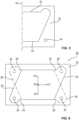
- the preheating device 10 has a first side 12 with a first preheating structure 14. This is shown in figure 1 .
- the first preheating structure 14 is asymmetric with respect to the first centerline, i.e., the first axis X, and with respect to the second centerline, i.e., the second axis Y. Consequently, the first axis X and the second axis Y are each an axis of asymmetry.
- the image on one side of one of the centerlines or axes is not mirror-symmetrical with respect to the other side of the respective centerline or axis.
- the remaining of the first or the second centerline is an axis of symmetry, in particular in case of a component having a rectangular shape.
- the preheating arrangement comprises a first rotating means for rotating the preheating device 10 between the first position and the second position.
- a plurality of components is welded to each other.
- An exemplary first component 20 is described with respect to figures 3 to 8 .
- the second welding structure 28 is congruent with the first welding structure 24 and, thus, also congruent with the first 14 and second preheating structure 18. Accordingly, these structures 14, 18, 24, 28 have the same size and shape.
- the second welding structure 28 could be rotated compared to the first welding structure 24 around the third axis ZC, which is perpendicular to the plane, by a certain degree ⁇ .
- the rotation around the third axis ZC could be 180°.
- a rotation by 180° is, regardless of other possible rotation angles, particularly preferred.
- the welding structures 24, 28 are asymmetrical with respect to both centerlines, a rotation by other angle values unequal to 0° and 360° may be useful.
- the preheating arrangement is moved from the preheating position back to the parking position.
- the lifting table i.e., the lower support 5
- the lifting table is moved along the third axis Z into the welding position in which the first and the second component 20 or the stack of welded components are in abutment and welded to each other, for example by means of vibration welding or IR welding.
- the lower support 3 is moved relative to the upper support 1 back to its initial position.
- the stack of components is maintained in the lower tool.
- the side of the stack of welded components facing the upper tool or upper support 1 corresponds to the side of the former first component 20 which was arranged in the upper tool during the first cycle.
- This side, which has the second welding structure 28, represents now the third welding structure of the stack of welded components.
- another first component 20 is arranged in the upper tool.
- the stack of welded components determines the welding structure and, in particular, the orientation thereof, the new first component 20 must be arranged in the upper tool such that second side having the second welding structure 28 faces the lower tool, i.e., the stack of welded components arranged therein.
- the preheating arrangement is rotated, particularly in the parking position, from the first position to the second position, as shown in figure 2 and explained above.
- the preheating structures 14, 18 match in the preheating position of the preheating arrangement again the exposed welding structures, i.e., here the second welding structure 28 and the corresponding third welding structure.
- the second cycle can be performed with a reliable preheating of the respective welding structures 28 by means of the preheating arrangement.
- the cycle may be repeated.
- This third cycle would correspond in general to the first cycle.
- the preheating arrangement must be rotated back into the first position.
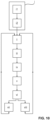
- a first step A the preheating arrangement is moved from a parking position into a preheating position between the upper and the lower tool of a welding device.
- the preheating device of the preheating arrangement is arranged in the first position having the first orientation in which the preheating structures 14, 18 overlay the welding structures 24 or 28 in the preheating position, when viewed along the third axis Z.
- the upper support 1 as well as the lower support 3 of the welding device are arranged in the preheating position each in a plane parallel to the first plane.
- step B the first component 20 and the second component or the stack of welded components are preheated in step B.
- step C the preheating arrangement is moved from the preheating position into the parking position.
- the further step D of rotating the preheating arrangement by means of the at least one first rotating means from the first position into the second position is performed.
- This rotation takes place according to one alternative during or after the preheating arrangement has been moved from the preheating position to the parking position.
- the rotating may be performed at any time in the parking position, for example during a loading of a new first component to be welded into the welding device.
- this step is performed during or before the preheating arrangement is moved from the parking position to the preheating position.
- the second component or the stack of welded components comprises at the side facing the first component 20 a third welding structure which is oriented such that, when viewed along the third axis Z, the third welding structure is arranged above the welding structure 24, 28 of the first component 20 facing the second component or facing the stack of welded components.
- a first step i the first component 20 is arranged with the first side in the upper tool.
- This step i comprises in the described embodiment the further steps i1 of arranging the first component 20 in the lower tool, preferably on the second component or on the stack of welded components, and i2 of moving the lower support 3 with the first component 20 relative to the upper support 1 along the third axis Z from the initial position to a transfer position.
- the user places the first component 20 on the lower tool, which is then moved for transferring the first component 20 to the upper tool. This eliminates the manual step of arranging the first component in the upper tool.
- step ii a moving of the lower support 3 having the lower tool with the second component or the stack of welded components arranged therein relative to the upper support 1 into an intermediate position takes place in step ii.
- the lower support 3 with the second component or with the stack of welded components is moved in step iv relative to the upper support 1 along the third axis Z to the welding position.
- a welding of the first component 20 to the second component or to the stack of welded components takes place in step v so that an increased stack of welded components results. This increase of the stack is considered in every subsequent cycle when approaching the welding position.
- the lower support 3 is moved back to the initial position in step vi.
- the welding method comprises now the step vii of arranging another first component 20 in the upper tool. This is performed such that the welding structure on the side facing the lower tool matches the third welding structure exposed by the stack of welded components in the lower tool. Subsequently, above steps ii to vi of moving the lower support 3 to the intermediate position, performing the inventive preheating method, moving the lower support 3 into the welding position, welding the components to each other and moving the lower support 3 to the initial position are repeated. However, it must be considered that the preheating device 10 has been rotated prior to the preheating in this cycle and is, thus, arranged in the second position.
- the preheating arrangement is arranged such that the preheating structures 14, 18 match the orientation of the welding structures 24, 28 of the components to be welded to each other.
- the welding method comprises after the step vi of moving the lower support 3 back to the initial position the step viii of arranging a third component (not shown) in the upper tool.
- the third component comprises on the first side a fourth welding structure and on the opposite second side a fifth welding structure.
- the fourth and the fifth welding structure correspond to the third welding structure and are oriented such that, when viewed along the third axis perpendicular to the first plane, the fourth and the fifth preheating structure are arranged one above the other.
- the third component is arranged in the upper tool such that the welding structure on the side facing the lower tool matches the third welding structure exposed by the stack of welded components in the lower tool.
- the third component may be welded to the stack of welded components.
- the third component corresponds to the first component in that it has the same welding structure. Nevertheless, it differs from the first component in that the respective welding structures are not rotated with respect to each other. In other words, they are arranged one above the other, like the orientation of the preheating structures 14, 18 of the preheating device 10.
- the preheating device 10 is not rotated every time it is placed in the parking position but only in case it is required. This makes the welding method more flexible and allows the production of a stack consisting of at least two different types of components.
- the first type being the above described first component
- the second type being the third component.
- an embodiment of an inventive retrofitting method for a welding device comprises initially the step I of providing an inventive preheating arrangement. Subsequently, the preheating arrangement is incorporated in step II into the welding device. Finally, and in step III, the preheating arrangement is implemented into the control method of the welding device.
- an already existing welding device for example a vibration welding device or an IR welding device, is equipped with the inventive preheating arrangement so that it realizes the above discussed technical effects and advantages.
Landscapes
- Engineering & Computer Science (AREA)
- Mechanical Engineering (AREA)
- Physics & Mathematics (AREA)
- Electromagnetism (AREA)
- Health & Medical Sciences (AREA)
- Toxicology (AREA)
- Thermal Sciences (AREA)
- Oral & Maxillofacial Surgery (AREA)
- Lining Or Joining Of Plastics Or The Like (AREA)
- Arc Welding In General (AREA)
Description
- The present invention is related to a preheating arrangement for a welding device, a respective welding device, a preheating method using the preheating arrangement, a welding method using the welding device as well as a retrofitting method.
- Preheating arrangements are generally known, in particular in combination with welding devices for welding two components, in particular plastic components, to each other.
- Usually, the welding devices comprise a frame or a housing with a lower tool arranged therein as well as an upper tool arranged therein. The lower tool is fastened to a lifting table, whereas the upper tool is rigidly mounted to an upper tool plate. By means of the lifting table, the lower tool can be moved in the direction of the upper tool to weld a first component in the lower tool to a second component in the upper tool by means of friction or vibration welding.
- Such welding devices are used for example in the automotive industry or in the medical technology. In the automotive industry, the welding devices are used for producing lights but may be used also in the production of other components or component groups which consist of plastic or contain plastic. In a similar way, the welding device may be used in the production of devices and/or component groups in the medical technology or in the production of consumer goods.
- The basic operation of the welding device including a preheating arrangement is as follows. At first a user places a first component on the lower tool. Subsequently, he positions a second component on the first component in the lower tool. Then, the lifting table with the lower tool and the components arranged thereon moves along the vertical axis from an initial position in the direction of the upper tool until the second component is received in the upper tool.
- The lifting table now moves back into a position, in which the preheating arrangement can be arranged from an idle or parking position in an aligning or preheating position between the two components. After the preheating arrangement has been arranged between the two components, the two components are preheated at the points to be welded. For this purpose, the preheating arrangement has a respective preheating structure. Subsequently to the preheating, the preheating arrangement is moved back into the idle or parking position.
- Then, the lifting table is moved into a welding position and a welding of the first component to the second component takes place, in particular by means of friction or vibration welding. After finishing the welding, the lifting table moves with the lower tool and the compound of first and second component arranged thereon along the vertical axis from the welding position back into the initial position. As soon as the lifting table has reached the initial position, the user removes the compound of first and second component.
- An example of a welding device including a preheating arrangement is described in
EP 3 009 254 A2 - A disadvantage of the above-described welding device and, thus, of the preheating arrangement becomes apparent if several components shall be welded to each other which have a complex congruent welding structure which is oriented differently between the two sides of the component.
- For example, it is assumed that the components to be welded have a rectangular shape and define a plane by means of a first centerline extending between and parallel to the longitudinal sides and a second centerline extending between and parallel to the transverse sides of the rectangle. Each component comprises on a first side a first welding structure and on an opposite second side a second welding structure. Both welding structures are congruent and asymmetric with respect to the first centerline. Further, it is assumed that the welding structure on the second side is rotated by 180° around an axis being perpendicular to the plane. Thus, and when viewed along this axis, i.e., from above onto and through the component, the first and the second welding structure have different orientations such that they do not completely overlap each other.
- In a first cycle, the worker would place one component in the lower tool and another component in the upper tool. Here, he would have to focus on the orientation of the welding structures such that the welding structure of the component in the upper tool which faces the lower tool corresponds to the welding structure of the component in the lower tool facing the upper tool.
- After arranging the components correctly in the welding device, the welding method is performed including the preheating by means of the preheating arrangement having the respectively oriented preheating structures. Already here, it must be considered that for a reliable preheating the preheating structure of the preheating arrangement is adapted to the welding structure to be preheated.
- Subsequently to the first cycle, the component which was at the beginning of the cycle in the upper tool defines now the new, i.e., differently oriented, welding structure with the side facing the upper tool. Thus, the welding structure of this side, which was in the first cycle received in the upper component, is oriented differently, i.e., 180° rotated around the third axis, as explained above. As a result, the preheating structure of the preheating arrangement does not match the welding structure and, therefore, cannot ensure a reliable preheating of this component. The same applies with respect to the welding structure of a respective component arranged in the upper tool such that both components have matching welding structures.
- An injection mold for manufacturing a part is described in
EP 3 012 081 A1 -
DE 10 2017 010 550 A1 describes a device for thermally welding workpieces including a heating element and a shielding gas supply. The device includes a heating plate consisting of a thermal insulating material in which a groove is formed, said groove includes a heating element, relative to which a surface of a workpiece to be welded is positioned in close proximity to the heating element. A feed channel for a shielding gas is formed in the heating plate and communicates with the groove via at least one through-channel, and the feed channel for supplying shielding gas can be connected to a shielding gas source via a feed line and a valve. The device may further include an assembly for welding a first and a second workpiece, said assembly includes a first and second movement device for moving the workpieces towards one another. - Further, a method and device for welding plastic parts, in particular for connecting plastic parts along a weld line, is described in
EP 1 415 789 A1 - Finally,
JP 2001-297608 - It is therefore a problem of the present invention to provide a preheating arrangement by means of which the above disadvantage can be overcome so that a plurality of components which shall be welded to each other for forming a stack of welded components are preheated with low effort as well as in an easy and reliable manner. Further, it is a problem to provide a respective welding device, a preheating method as well as a welding method.
- The above problem is solved by a preheating arrangement according to
independent claim 1, a welding device according to independent claim 6, a preheating method according to independent claim 8 as well as a welding method according toindependent claim 10 and a retrofitting method according toindependent claim 14. Further preferred embodiments and developments result from the following description, the drawings as well as the appending claims. - An inventive preheating arrangement for a welding device having an upper tool mounted to an upper support and a lower tool mounted to a lower support, wherein the upper and the lower support are movable relative to each other between an initial position and a welding position, comprises a preheating device defining a first plane by means of a first centerline extending along a first axis and a second centerline extending along a second axis being perpendicular to the first axis and the preheating device has a first side with a first preheating structure and an opposite second side with a second preheating structure, wherein the first preheating structure is asymmetric with respect to the first and/or the second centerline so that the respective axis is an axis of asymmetry, and the second preheating structure corresponds to the first preheating structure and is oriented like the first preheating structure such that, when viewed along a third axis perpendicular to the first plane, the first and the second preheating structure are arranged one above the other, wherein the preheating arrangement comprises further a first rotating means for rotating the preheating device between a first position and a second position such that the preheating structures in the first position have a first orientation and in the second position a second orientation in which they are rotated around the axis of asymmetry by 180° compared to the first orientation or in which they are rotated by an angle α in the range of 0° < α < 360°, preferably 90° ≤ α ≤ 270° and particularly preferred α = 180° around the third axis compared to the first orientation.
- In the following, the inventive preheating arrangement will be explained based on its use in a welding device. In this regard, particularly the process of preheating is considered. The exemplary welding device comprises, besides the inventive preheating arrangement, a lower tool mounted to a lower support and an upper tool mounted to an upper support. The lower and the upper support are movable relative to each other between an initial position and a welding position. The preheating arrangement is movable between a parking position and a preheating position such that the preheating arrangement is arranged in the preheating position between the upper and the lower support. Further, the upper and the lower support are each arranged in a plane parallel to the first plane defined by the preheating device when the preheating arrangement is in the preheating position. The term third axis refers, thus, to an axis being perpendicular to the respective plane.
- By means of this welding device, a plurality of components is welded to each other, according to the now described example. Each of these components comprises on a first side a first welding structure and on an opposite second side a second welding structure. The first and the second welding structure are formed congruent with the first and the second preheating structure of the preheating device. Congruent means in this regard that it has the same shape and size. Thus, the first and the second preheating structure as well as the first and the second welding structure are identical in terms of shape and size.
- Further, the first and the second welding structures are oriented such that the first welding structure and the second welding structure are rotated with respect to each other around the axis of asymmetry by 180° or around the third axis by the angle α. In other words, and according to a particularly preferred embodiment, the welding structures are rotation symmetric with respect to each other. Specifically, a rotation of one of the welding structures around at least one of the first and the second centerline by 180° results in the other or opposite welding structure.
- For an easier understanding of this feature, a component having a rectangular shape is assumed. A first centerline of the component extends parallel to and between the transverse sides of the component. A second centerline extends parallel to and between the longitudinal sides of the component. The first and the second centerline define, as a result, a plane and separate the component into four geometrically equal parts. The point of intersection of the centerlines indicates the geometric center of the component. In the further course of this example, it is assumed that the component is watched in horizontal or landscape format meaning that the longitudinal sides extend from left to right.
- On the first side of the component, a first welding structure is arranged. This welding structure is, for example, formed like a rectangle with rounded corners, wherein the first welding structure has a protrusion in each of two adjacent corners. Referring to the four geometrically equal parts into which the component is divided by the centerlines, it is assumed that the two protrusions of the welding structure are present in the upper left and the upper right part of the first side of the component when viewing the first side from above, i.e., along the third axis extending perpendicular to the plane. As a result, the second centerline extending between and parallel to the longitudinal sides is an axis of asymmetry whereas the first centerline extending between and parallel to the transverse sides is an axis of symmetry. Although this is an exemplary implementation, it is preferred that the remaining of the first or the second centerline is an axis of symmetry, in particular in case of a component having a rectangular shape.
- On the second side of the component, a second welding structure is arranged. This welding structure is congruent with the first welding structure. Thus, and as explained above, it has the same size and shape. However, the second welding structure is arranged in a different orientation on the second side compared to the first welding structure on the first side.
- This different orientation is achieved in that the second welding structure is arranged on the second side in a rotated manner compared to the first welding structure. As a result, the first and the second welding structures are arranged such that they are not arranged completely one above the other when viewed from above the first or the second side and through the component.
- The term one above the other indicates that a shadow of one structure which is caused by an imaginary light shining from one side through the component covers the other structure completely. Thus, and as the welding structures are not arranged one above the other, i.e., completely one above the other, the second welding structure must have a different orientation compared to the first welding structure.
- Such different orientation can be achieved either by rotating the second welding structure compared to the first welding structure around the axis of asymmetry by 180° or by rotating the second welding structure compared to the first welding structure about the third axis, which is perpendicular to the plane, by a certain degree α.
- A rotating of the second welding structure on the second side compared to the first welding structure around the axis of asymmetry by 180° would, with respect to the above example, lead to the fact that the two protrusions are arranged at the lower left and the lower right part. This applies when the component is viewed from the first side and through the component.
- Due to this, and in case the component is turned from a position in which the first side can be seen around the axis of asymmetry, i.e., around the longitudinal centerline, to a position in which the second side can be seen, the second welding structure will expose the same orientation to the observer as the first welding structure. On the other hand, and in case the component is turned from the first side to the second side around the axis of symmetry, i.e., around the transverse centerline, the second welding structure will expose a different orientation compared to the first welding structure. In particular, the two protrusions would be present on the second side in the lower part of the component whereas they are present on the first side in the upper part.
- Alternatively, the second welding structure could be rotated compared to the first welding structure about the third axis, which is perpendicular to the plane, by a certain degree α. With respect to the above first example of rotating, and in case the second welding structure is rotated by 180° around the third axis, the result would be the same compared to the rotating about the axis of asymmetry. Thus, a rotation by 180° is, regardless of other possible rotation angles, particularly preferred. Nevertheless, and in particular in case the welding structures are asymmetrical with respect to both centerlines, a rotation by other angle values unequal to 0° and 360° may be useful and preferred.
- That said with respect to the general design of the components to be welded to each other, the welding method, and thus, the preheating method will be explained with respect to several exemplary welding cycles.
- Initially, the first component is arranged in the upper tool and a second component, being identical to the first component or having a matching or identical welding structure, is arranged in the lower tool. As an alternative, a stack of welded components is already present in the lower tool. In this case, the side of the stack of welded components facing the first component has a third welding structure. In each case, the first component and the second component or the first component and the stack of welded components are arranged such that their welding structures match each other.
- For an easier understanding, and with respect to the above exemplary component and its welding structure, it is assumed that the first component is arranged such that the first side having the first welding structure faces the lower tool and the second side having the second welding structure is arranged in the upper tool. Consequently, the second component, which is for example identical to the first component, is arranged in the lower tool such that the first side having the first welding structure faces the upper tool, i.e., the first side of the first component in the upper tool. For sake of clarity, the welding structure exposed by the second component or stack of welded components is referred to as third welding structure. This will become clear in the subsequent second cycle.
- As initially discussed, the first component is held in the upper tool by means of an underpressure. Furthermore, and for the exemplary operation, the upper support of the welding device is an upper mounting plate, and the lower support is a lifting table, preferably a lifting table driven by an electric motor. In use, the lower support with the lower tool is moved relative to the upper support along the third axis.
- Consequently, and after the first component has been arranged in the upper tool, the lifting table moves along the third axis into an intermediate position in which the preheating arrangement can be moved from the parking position into the preheating position between the components.
- To this end, the preheating arrangement is arranged in the first position, in which the preheating structures arranged on the first and second side match the welding structures. In other words, in case the welding device is viewed along the third axis, i.e., the axis perpendicular to the first plane, the welding structures and the preheating structures are arranged one above the other, specifically completely. Thus, only one structure can be seen from this perspective when watching through the individual parts and components. The first plane may also be referred to as vibration welding plane in case of a vibration welding device.
- As the preheating structures of the preheating arrangement must match the welding structures, the preheating structures must also be congruent to the welding structures and to each other, as explained above. Furthermore, and contrary to the welding structures of one component, the preheating structures of the preheating device must be oriented in the same manner, i.e., they must be arranged one above the other, particularly completely, when viewed from above and along the third axis, respectively, and through the preheating device. Thus, as discussed above, the term one above the other indicates that a shadow of one structure which is caused by an imaginary light shining from one side through the component covers the other structure completely. As the preheating structures are arranged completely one above the other, the second preheating structure must have the same orientation compared to the first preheating structure.
- In this regard, it is particularly preferred that the preheating device has a rectangular shape, and the first axis extends parallel to the transverse sides of the rectangle whereas the second axis extends parallel the longitudinal sides of the rectangle, as discussed above for the exemplary first component.
- After the preheating arrangement has been arranged between the two components, the welding structures of the two components are preheated by means of the matching preheating structures. Thus, the preheating structures overlay the welding structures in the preheating position. In this regard, the first and the second preheating structure are preferably IR preheating structures.
- Subsequently to the preheating, the preheating arrangement is moved from the preheating position back to the parking position. Thereafter, the lifting table is moved along the second axis into the welding position in which the first and the second component or the stack of welded components are in abutment and welded to each other, for example by means of vibration welding or IR welding. After the welding, the lower support is moved relative to the upper support back to its initial position.
- As a result, a stack of welded components consisting of the first and the second component is now present in the lower tool. Contrary to the known methods, the stack of components is maintained in the lower tool. Thus, the side of the stack of welded components facing the upper tool corresponds to the side of the former first component which was arranged in the upper tool during the first cycle. This side having the second welding structure represents now the third welding structure of the stack of welded components.
- In the following second cycle, a new first component is arranged in the upper tool. As the stack of welded components determines the welding structure, the new first component must be arranged in the upper tool such that second side having the second welding structure faces the lower tool or the stack of welded components arranged therein.
- Now, the above-described process is repeated. As the orientation of the welding structures has changed from the first welding structure to the second welding structure, the former arrangement of the preheating device is not suitable and would not guarantee a reliable preheating of the welding structures in this cycle.
- For overcoming this, the preheating arrangement is rotated, particularly in the parking position, from the first position to the second position. In this second position, the preheating device of the preheating arrangement has a second orientation in which the preheating structures are rotated around the axis of asymmetry by 180° compared to the first orientation or in which they are rotated by an angle α in the range of 0° < α < 360°, preferably 90° ≤ α ≤ 270° and particularly preferred α = 180° around the third axis compared to the first orientation. In the present example, in which the welding structures and, thus, the preheating structures are rectangular with rounded corners and one protrusion in each of two adjacent corners, a rotation around the axis of asymmetry by 180° or a rotation around the third axis by 180° leads to the desired result. Nevertheless, the latter is only possible for specific designs of the welding structures and, thus, of the preheating structures, as will be explained later with respect to the specific embodiments.
- After such rotating, the preheating structures match in the preheating position of the preheating arrangement the exposed welding structures, i.e., here the second welding structure and the corresponding third welding structure. Thus, the second cycle can be performed with a reliable preheating of the respective welding structures by means of the preheating arrangement.
- After the preheating and the welding have been performed, as described above, the cycle may be repeated. This third cycle would correspond in general to the first cycle. Thus, the preheating arrangement must be rotated back into the first position.
- In general, the cycle and, thus, the welding of a new first component to the stack of welded components is repeated until a stack of welded components is present having the desired number of layers or thickness.
- A general positive effect of the preheating is that solid to solid friction, in case of friction or vibration welding of the components, is skipped at the beginning of the welding process. Thus, particulate formation is at least partially prevented, and a clean joint may be obtained. Furthermore, and again with respect to a vibration welding, the friction forces are reduced, and lower amplitudes may be used to create the weld between the components to be welded. These reduced forces are advantageous in case the components to be welded are structurally less stable and are prone to bending, which usually results in amplitude loss and a poor welding connection.
- Accordingly, and even in case the components are prone to bending, a reliable welding connection can be established by means of the inventive preheating arrangement.
- Additionally, and specifically due to designing the preheating arrangement such that it can be rotated, whereby the preheating structures match the welding structures to be preheated in each cycle, the method is simple, and the construction of the device is space-saving. Neither a further preheating arrangement is required for providing a preheating structure adapted to the welding structures to be preheated nor must the stack of welded components be removed and re-arranged in a different orientation in the lower tool. This reduces the complexity of the device as well as of the control method and the required installation space while maintaining at the same time a high weld quality.
- For the sake of completeness, it is pointed out that the preheating device may also define a second plane perpendicular to the first plane. For example, and with respect to the above-mentioned rectangle, the welding device may have the shape of a cuboid wherein on opposite surfaces congruent preheating structures are arranged. Thus, the application field for the respective preheating device could be further increased. Assuming that the preheating structures are present with respect to the rotation axis on the surfaces being parallel thereto, a rotation by 180° must be performed for changing between the first and the second position, i.e. using the first and the second preheating structure, whereas a rotation by 90° must be performed to use the other preheating structures, i.e. the third and the fourth preheating structure. After a change of the preheating structure, the above describe steps are performed analogously.
- In a preferred embodiment of the preheating arrangement, the first rotating means is used for rotating the preheating device around an axis in the first plane being parallel to the axis of asymmetry, around the axis of asymmetry or around the third axis. As explained above, the rotation around the third axis is only useful for specific designs of preheating structures and components to be welded. Thus, and particularly advantageous is the embodiment, in which the first rotating means is used for rotating the preheating device around the axis of asymmetry or around an axis which is arranged in the first plane and is parallel to the axis of asymmetry. This is because after the rotation by 180° around such axis, regardless of whether it is the axis of asymmetry itself or an axis parallel thereto and in the first plane, leads to the same result.
- An inventive welding device for welding a first component to a second component or to a stack of welded components, comprises an upper tool mounted to an upper support for receiving the first component and a lower tool mounted to a lower support for receiving the second component or the stack of welded components as well as an inventive preheating arrangement, wherein the preheating arrangement is movable between a parking position and a preheating position such that the preheating arrangement is arranged in the preheating position between the upper and the lower support, wherein in the preheating position the upper and the lower support are each arranged in a plane parallel to the first plane, and the upper and the lower support are movable relative to each other between an initial position and a welding position. The inventive welding device has been discussed above during the explanation of the functioning of the inventive preheating arrangement. Accordingly, it is referred to the above discussion for avoiding unnecessary repetitions. The same applies with respect to the resulting technical effects and advantages.
- In a preferred embodiment of the welding device, the welding device is a vibration welding device or an infrared welding device. By means of this embodiment, the inventive preheating device may be either used with a vibration welding device or in combination with an IR welding device. Consequently, the field of applications for the inventive preheating arrangement is increased and adapted to the components to be welded.
- An inventive preheating method for preheating a first component and a second component or a stack of welded components by means of the inventive preheating arrangement, wherein the first component comprises on a first side a first welding structure and on an opposite second side a second welding structure, the first and the second welding structure being formed congruent with the first and the second preheating structure of the preheating device and oriented such that the first welding structure and the second welding structure are rotated with respect to each other around the axis of asymmetry by 180° or around the third axis by the angle α, and the second component or the stack of welded components comprises at the side facing the first component a third welding structure which is oriented such that, when viewed along the third axis, the third welding structure is arranged above the welding structure of the first component facing the second component or facing the stack of welded components, wherein the preheating method comprises the steps of: moving the preheating arrangement from a parking position into a preheating position between the upper and the lower tool of a welding device, wherein the preheating device of the preheating arrangement is arranged in the first position having the first orientation in which the preheating structures overlay the welding structures in the preheating position, when viewed along the third axis, and an upper support as well as a lower support of the welding device are arranged in the preheating position each in a plane parallel to the first plane, preheating the first component and the second component or the stack of welded components, and moving the preheating arrangement from the preheating position into the parking position. This preheating method has been described already in combination with the inventive preheating arrangement. Thus, and for avoiding redundancies, it is referred to the respective explanations with respect to the course of procedure, the technical effects as well as the advantages.
- In a preferred embodiment of the preheating method, it comprises after the step of preheating the further step: rotating the preheating arrangement, preferably in the parking position, by means of the at least one rotating means from the first position into the second position. This makes it possible that in intermediate steps also components similar to the first component but having welding structures which are not rotated with respect to each other may be integrated into the stack of components. This further increases the application field for the preheating arrangement and, thus, the preheating method in case a stack of components shall be provided in which not every component is a first component but only, for example, every other component. Of course, any other pattern may be used, too. Regarding the rotating of the preheating arrangement, this can also take place during a movement from the parking position to the preheating position, during a movement from the preheating position to the parking position or at any time in the parking position, for example during a loading of a new first component to be welded into the welding device.
- An inventive welding method for welding a first component to a second component or to a stack of welded components by means of the inventive welding device, wherein the first component comprises on a first side a first welding structure and on an opposite second side a second welding structure, the first and the second welding structure being formed congruent with the first and the second preheating structure of the preheating device and oriented such that the first welding structure and the second welding structure are rotated with respect to each other around the axis of asymmetry by 180° or around the third axis by the angle α, and the second component or the stack of welded components comprises at the side facing the first component a third welding structure which is oriented such that, when viewed along the third axis, the third welding structure is arranged above the welding structure of the first component facing the second component or facing the stack of welded components, wherein the welding method comprises the steps of: arranging the first component with the first side in the upper tool, moving the lower support having the lower tool with the second component or the stack of welded components arranged therein relative to the upper support into an intermediate position, performing the inventive preheating method, wherein the preheating device is arranged in the first position, moving the lower support with the second component or with the stack of welded components relative to the upper support along the third axis to the welding position, welding the first component to the second component or to the stack of welded components so that an increased stack of welded components results, thereafter moving the lower support back to the initial position. Like the preheating method, the welding method has been described also above in combination with the inventive preheating arrangement. Thus, it is referred to these statements with respect to the course of procedure, the technical effects as well as the advantages.
- In a preferred embodiment of the welding method, the step of arranging the first component in the upper tool comprises the steps of: arranging the first component in the lower tool, preferably on the second component or on the stack of welded components, and moving the lower support with the first component relative to the upper support along the third axis from the initial position to a transfer position. By means of these method steps, the user places the first component on the lower tool, which is then moved for transferring the first component to the upper tool. This eliminates the manual step of arranging the first component in the upper tool.
- In a further preferred embodiment of the welding method, it comprises after the step of moving the lower support back to the initial position the further steps of: arranging another first component in the upper tool such that the welding structure on the side facing the lower tool matches the third welding structure exposed by the stack of welded components in the lower tool and repeating the steps of moving the lower support to the intermediate position, performing the inventive preheating method, moving the lower support into the welding position, welding the components to each other and moving the lower support to the initial position, wherein the preheating device has been rotated and is arranged in the second position. By means of this method step, it is ensured that in case a new first component shall be welded to the stack of welded components, the preheating arrangement is arranged such that the preheating structures match the orientation of the welding structures of the components to be welded to each other.
- Preferably, the welding method comprises after the step of moving the lower support back to the initial position the further steps of: arranging a third component in the upper tool, wherein the third component comprises on the first side a fourth welding structure and on the opposite second side a fifth welding structure, wherein the fourth and the fifth welding structure correspond to the third welding structure and are oriented such that, when viewed along a third axis perpendicular to the first plane, the fourth and the fifth preheating structure are arranged one above the other, and wherein the third component is arranged in the upper tool such that the welding structure on the side facing the lower tool matches the third welding structure exposed by the stack of welded components in the lower tool, and repeating the steps of moving the lower support to the intermediate position, performing the inventive preheating method, moving the lower support into the welding position, welding the components to each other and moving the lower support to the initial position, wherein the preheating device is maintained in the first or second position. This separate step allows that the third component may be welded to the stack of welded components. The third component corresponds to the first component in that it has the same welding structure. Nevertheless, it differs from the first component in that the respective welding structures are not rotated with respect to each other. In other words, they are arranged one above the other, like the design of the preheating structures of the preheating device. Consequently, and in combination with the former preferred method step, the preheating device is not rotated every time it is placed in the parking position but only in case it is required. This makes the welding method more flexible and allows the production of a stack consisting of at least two different types of components. The first type being the above described first component, the second type being the third component.
- In this regard, and with respect to each of the above mentioned preferred further method steps, the arranging of the further first or of the third component may comprise the steps of arranging the first or third component in the lower tool, preferably on the second component or on the stack of welded components, and moving the lower support with the first or third component relative to the upper support along the third axis from the initial position to a transfer position.
- An inventive retrofitting method for a welding device, comprises the steps of: providing an inventive preheating arrangement, incorporating the preheating arrangement into the welding device, and implementing the preheating arrangement in the control method of the welding device. By means of this method, an already existing welding device, for example a vibration welding device or an IR welding device, may be equipped with the inventive preheating arrangement so that it realizes the above discussed technical effects and advantages.
- In the following, the present invention will be described in detail based on the drawings. In the drawings, the same reference signs denote the same elements and/or components. It shows:
- Figure 1
- shows an embodiment of an inventive welding device having an embodiment of the inventive preheating arrangement arranged in a first position,
- Figure 2
- shows an embodiment of the inventive welding device having the embodiment of the inventive preheating arrangement arranged in a second position,
- Figure 3
- shows a first side of a first component for illustrating the welding structure,
- Figure 4
- shows the first side of the first component of
Figure 3 wherein the first and the second centerline is indicated, - Figure 5
- shows an enlarged view of the right side of the first component of
Figure 4 , - Figure 6
- shows the first component of
Figure 3 in which additionally a second welding structure on the opposite second side is illustrated, - Figure 7
- shows the first component of
Figure 6 wherein the first and the second centerline is indicated, - Figure 8
- shows an enlarged view of the right side of the first component of
Figure 7 , - Figure 9
- shows a flow chart of an embodiment of the inventive preheating method,
- Figure 10
- shows a flow chart of an embodiment of the inventive welding method and
- Figure 11
- shows a flow chart of an embodiment of the inventive retrofitting method.
- Embodiments of the inventive preheating arrangement are described in the following specifically with respect to the functioning thereof when it is used in a welding device. In general, the welding device and, thus, the preheating arrangement may be used in the automotive industry or in the medical technology. In particular, it may be used in any application in which a plurality of components shall be welded by means of e.g., vibration or IR welding to each other in a reliable manner.
- First of all, and with respect to
figures 1 and 2 , an embodiment of an inventive vibration welding device comprising an embodiment of the inventive preheating arrangement is explained. The welding device comprises in a known manner an upper tool mounted to anupper support 1 for receiving afirst component 20. Further, the welding device comprises a lower tool mounted to alower support 3 for receiving the second component or the stack of welded components. The upper 1 and thelower support 3 are movable relative to each other between an initial position and a welding position. In the initial position, the components to be welded can be loaded into the welding device. In the welding position, the components in the welding device are in abutment so that they can be welded to each other. According to a first alternative, the welding device is a vibration welding device so that the components are welded to each other in the welding position by means of vibration welding. In a second alternative, the welding device is an infrared welding device so that the components are welded to each other in the welding position by means of IR welding. - During operation, the
first component 20 is held in the upper tool by means of an underpressure. Furthermore, and for the exemplary operation, theupper support 1 of the welding device is an upper mounting plate and thelower support 3 is a lifting table, preferably a lifting table driven by an electric motor. - Further, the welding device comprises a preheating arrangement. The preheating arrangement is movable between a parking position and a preheating position. In the preheating position, the preheating arrangement is arranged between the upper 1 and the
lower support 3. Accordingly, and with respect tofigures 1 and 2 , the preheating arrangement is arranged in the preheating position. - Now, the specific design of the preheating arrangement is further explained. The preheating arrangement comprises a preheating
device 10 having, in the shown example, a rectangular shape. This rectangular shape defines a first plane by means of a first centerline extending along a first axis X and a second centerline extending along a second axis Y being perpendicular to the first axis X. - In the embodiment shown, the first axis X and, thus, the first centerline extends parallel to and between the transverse sides of the rectangle whereas the second axis Y and, thus, the second centerline extends parallel to and between the longitudinal sides of the rectangle. The first and the second centerline define, as a result, the first plane and separate the
preheating device 10 into four geometrically equal parts. The point of intersection of the centerlines indicates the geometric center of the preheating device, in which the shown coordinate system has its origin. - As can be directly seen, he upper 1 and the
lower support 3 are each arranged in a plane parallel to the first plane in the preheating position. - The preheating
device 10 has afirst side 12 with afirst preheating structure 14. This is shown infigure 1 . Thefirst preheating structure 14 is asymmetric with respect to the first centerline, i.e., the first axis X, and with respect to the second centerline, i.e., the second axis Y. Consequently, the first axis X and the second axis Y are each an axis of asymmetry. In other words, the image on one side of one of the centerlines or axes is not mirror-symmetrical with respect to the other side of the respective centerline or axis. Although this is an exemplary implementation, it is particularly preferred that the remaining of the first or the second centerline is an axis of symmetry, in particular in case of a component having a rectangular shape. - In
figure 2 , the opposite second side 16 of the preheatingdevice 10 is illustrated. The second side 16 has asecond preheating structure 18. Thissecond preheating structure 18 corresponds to thefirst preheating structure 14. In particular, it is formed congruent with thefirst preheating structure 14. Congruent means in this regard that it has the same shape and size. Thus, the first 14 and thesecond preheating structure 18 are identical in terms of shape and size. - Furthermore, the
second preheating structure 18 is oriented like thefirst preheating structure 14 such that, when viewed along a third axis Z perpendicular to the first plane, the first 14 and thesecond preheating structure 18 are arranged one above the other. The term one above the other indicates that a shadow of one structure which is caused by an imaginary light shining from one side through the preheatingdevice 10 covers the other structure completely. Thus, and as the preheatingstructures second preheating structure 18 must have the same orientation as thefirst preheating structure 14. This is also based on the fact that later, during use of the welding device, two components shall be welded to each other having matching welding structures, as will be explained below. - Further, and again with respect to the preheating arrangement, it must be noted when comparing
figures 1 and 2 , that the position of the preheatingdevice 10 has changed from a first position infigure 1 to a second position infigure 2 . This can be seen, for example, due to the two recesses in the longitudinal side of the preheating device 5. For performing this change in the position, the preheating arrangement comprises a first rotating means for rotating the preheatingdevice 10 between the first position and the second position. - Based on the desired later operation, the first and the second position differ from each other in that the preheating
structures figures 1 and 2 as thewelding device 10 has been rotated around the second centerline, i.e., the Y-axis as axis of asymmetry. - According to an alternative, and in particular in case the preheating structure is mirror-symmetrical with respect to one of the first and the second centerline, it is also preferred to rotate the preheating
structures device 10 is rotated by 180° around the third axis Z, the result would be identical to a rotation around the axis of asymmetry. - Based on the above, the first rotating means is used for rotating the preheating
device 10 around an axis in the first plane being parallel to the axis of asymmetry, i.e., here the second axis Y, or around the axis of asymmetry for realizing the embodiment shown. For realizing other alternatives, the first rotating means may be used for rotating the preheatingdevice 10 around the third axis Z. Nevertheless, the rotation around the third axis Z is only useful for specific designs of preheatingstructures components 20 to be welded. - In addition to the first rotating means, the preheating arrangement can be equipped with further rotating means, for example a second rotating means for rotating around the third axis Z. Alternatively, the preheating arrangement may be provided with one rotating means per axis, which would result in three rotating means. Thus, the preheating arrangement is adapted to various preheating devices and preheating structures.
- For the sake of completeness, it is pointed out that the upper 1 and the
lower support 3 are each arranged in a plane parallel to the first plane defined by the preheating device 5 when the preheating arrangement is in the preheating position. The term third axis Z refers, thus, to the axis being perpendicular to the respective plane. - By means of the welding device, a plurality of components is welded to each other. An exemplary
first component 20 is described with respect tofigures 3 to 8 . - The
first component 20 has a rectangular shape, like the preheating device 5. Accordingly, a first centerline of the component, i.e., the axis XC (seefigure 3 ), extends parallel to and between the transverse sides of the component and a second centerline, i.e., the axis YC (seefigure 3 ), extends parallel to and between the longitudinal sides of thefirst component 20. The first and the second centerline define, as a result, a plane and separate the component into four geometrically equal parts. The point of intersection of the centerlines indicates the geometric center of the component, in which the point of origin for the coordinate system is shown. The third axis ZC extends perpendicular to the plane. - On a
first side 22 of thefirst component 20, afirst welding structure 24 is arranged. Thefirst welding structure 24 is formed congruent with the first 14 and the second 18 preheating structure of the preheatingdevice 10. As explained above, congruent means in this regard that it has the same shape and size. Thus, the first 14 and thesecond preheating structure 18 as well as thefirst welding structure 24 are identical in terms of shape and size. As a result, the first centerline, i.e., the first axis XC, and the second centerline, i.e., the second axis YC, are axes of asymmetry. In other words, the image on one side of one of the centerlines or axes is not mirror-symmetrical with respect to the other side of the respective centerline or axis. - On the second side of the
first component 20, asecond welding structure 28 is arranged. Thissecond welding structure 28 can be seen infigures 6 to 8 . These figures illustrate a view through the component so that thefirst welding structure 24 as well as thesecond welding structure 28 can be seen at the same time, although they are arranged on opposite sides. - The
second welding structure 28 is congruent with thefirst welding structure 24 and, thus, also congruent with the first 14 and second preheatingstructure 18. Accordingly, thesestructures - However, and as can be seen from
figures 6 to 8 , thesecond welding structure 28 is arranged in a different orientation on the second side compared to thefirst welding structure 24 on thefirst side 22. This different orientation is achieved in that thesecond welding structure 28 is arranged on the second side in a rotated manner compared to thefirst welding structure 24. In the embodiment shown, a rotation of thesecond welding structure 28 on the second side around the second axis YC by 180° results in thefirst welding structure 24. Thus, the first 24 and he second weldingstructure 28 are rotation-symmetric with respect to each other. - Turning back to
figures 6 to 8 and the view shown there, the first 24 and thesecond welding structures 28 overlay each other not completely, i.e., they are not arranged completely one above the other, when viewed from above thefirst side 22 and through thefirst component 20. The same applies in case thefirst component 20 is viewed from the second side. - The rotation for achieving such different orientation is performed by rotating the
second welding structure 28 compared to thefirst welding structure 24 around the second axis YC as axis of asymmetry by 180°. - Due to this, and in case the
first component 10 is turned from a position in which thefirst side 22 can be seen around the second axis YC as axis of asymmetry to a position in which the second side can be seen, thesecond welding structure 28 will expose the same orientation to the observer as thefirst welding structure 24. On the other hand, and in case thefirst component 20 is turned from thefirst side 22 to the second side around the first axis XC as axis of asymmetry, thesecond welding structure 28 will expose a different orientation compared to thefirst welding structure 24. - According to an alternative, and in particular in case the welding structure is mirror-symmetrical with respect to one of the first XC and the second axis YC, the
second welding structure 28 could be rotated compared to thefirst welding structure 24 around the third axis ZC, which is perpendicular to the plane, by a certain degree α. For example, the rotation around the third axis ZC could be 180°. Thus, a rotation by 180° is, regardless of other possible rotation angles, particularly preferred. Nevertheless, and in particular in case thewelding structures - That said with respect to the general design of the
first component 20 and, thus, of the components to be welded to each other, the welding method and the preheating method will be explained with respect to several exemplary welding cycles. - Initially, the
first component 20 is arranged in the upper tool and a second component, being either identical to thefirst component 20 or having at least on one side a third welding structure congruent with and matching one of the first 24 or thesecond welding structure 28 of thefirst component 20, is arranged in the lower tool. As an alternative, a stack of welded components is already present in the lower tool. In each case, thefirst component 20 and the second component or thefirst component 20 and the stack of welded components are arranged such that their welding structures match each other. - For an easier understanding, it is assumed that the
first component 20 is arranged in the upper tool such that thefirst side 22 having thefirst welding structure 24 faces the lower tool and the second side having thesecond welding structure 28 is arranged in the upper tool. Consequently, the second component, which is in this example identical to thefirst component 20, is arranged in the lower tool such that thefirst side 22 having thefirst welding structure 24 faces the upper tool, i.e., thefirst side 22 of thefirst component 20 in the upper tool. Later, the welding structure exposed by the second component or stack of welded components being present in the lower tool is referred to as third welding structure. - After the
first component 20 has been arranged in the upper tool, the lifting table moves along the third axis Z into an intermediate position in which the preheating arrangement can be moved from the parking position into the preheating position between thecomponents 20. - To this end, the preheating arrangement is arranged in the first position as shown in
figure 1 , in which the preheating structures arranged on the first 12 and second side 16 match thewelding structures 24 of thefirst component 20 in the upper and lower tool. In other words, in case the welding device is viewed along the third axis Z, thewelding structures 24 and the preheatingstructures - As the preheating
structures welding structures 24, the preheatingstructures device 10 must be oriented in the same manner, as discussed above. Thus, they must be arranged one above the other, particularly completely, when viewed from above and along the third axis Z, respectively, and through the preheatingdevice 10. - After the preheating arrangement has been arranged between the two
components 20, thewelding structures 24 of the twocomponents 20 are preheated by means of thematching preheating structures structures welding structures 24 in the preheating position. In this regard, the first 14 and thesecond preheating structure 18 are preferably IR preheating structures. - Subsequently to the preheating, the preheating arrangement is moved from the preheating position back to the parking position. Thereafter, the lifting table, i.e., the lower support 5, is moved along the third axis Z into the welding position in which the first and the
second component 20 or the stack of welded components are in abutment and welded to each other, for example by means of vibration welding or IR welding. After the welding, thelower support 3 is moved relative to theupper support 1 back to its initial position. - As a result, a stack of welded components consisting of the first and the
second component 20 or an increased stack of weldedcomponents 20 is now present in the lower tool. - Contrary to the known methods, the stack of components is maintained in the lower tool. Thus, the side of the stack of welded components facing the upper tool or
upper support 1 corresponds to the side of the formerfirst component 20 which was arranged in the upper tool during the first cycle. This side, which has thesecond welding structure 28, represents now the third welding structure of the stack of welded components. - In the following second cycle, another
first component 20 is arranged in the upper tool. As the stack of welded components determines the welding structure and, in particular, the orientation thereof, the newfirst component 20 must be arranged in the upper tool such that second side having thesecond welding structure 28 faces the lower tool, i.e., the stack of welded components arranged therein. - Now, the above-described process is repeated. However, and as the orientation of the welding structures has changed from the
first welding structure 24 to thesecond welding structure 28, the former position of the preheatingdevice 10 is not suitable and would not guarantee a reliable preheating of thewelding structures 28 in this cycle. - For overcoming this, the preheating arrangement is rotated, particularly in the parking position, from the first position to the second position, as shown in
figure 2 and explained above. After such rotating, the preheatingstructures second welding structure 28 and the corresponding third welding structure. Thus, the second cycle can be performed with a reliable preheating of therespective welding structures 28 by means of the preheating arrangement. - After the preheating and the welding have been performed, as described above, the cycle may be repeated. This third cycle would correspond in general to the first cycle. Thus, the preheating arrangement must be rotated back into the first position.
- In general, the cycle and, thus, the welding of another
first component 20 to the stack of welded components is repeated until a stack of welded components is present having the desired number of layers or thickness. - A general positive effect of the preheating is that solid to solid friction, in case of friction or vibration welding of the components, is skipped at the beginning of the welding process. Thus, particulate formation is at least partially prevented, and a clean joint may be obtained. Furthermore, and again with respect to a vibration welding, the friction forces are reduced, and lower amplitudes may be used to create the weld between the components to be welded. These reduced forces are advantageous in case the components to be welded are structurally less stable and are prone to bending, which usually results in amplitude loss and a poor welding connection. Accordingly, and even in case the components are prone to bending, a reliable welding connection can be established by means of the inventive preheating arrangement.
- Additionally, and specifically due to designing the preheating arrangement, in particular the preheating
device 10, such that it can be rotated, whereby the preheatingstructures welding structures - An embodiment of the inventive preheating method for preheating the
first component 20 and a second component or a stack of welded components by means of the inventive preheating arrangement is explained for further clarification with respect tofigure 9 . - As discussed above, the
first component 20 comprises on a first side 22 afirst welding structure 24 and on an opposite second side asecond welding structure 28. The first 24 and thesecond welding structures 28 are formed congruent with the first 14 and thesecond preheating structure 18 of the preheatingdevice 10 and oriented such that thefirst welding structure 24 and thesecond welding structure 28 are rotated with respect to each other around the axis of asymmetry by 180° or around the third axis by the angle α. The second component or the stack of welded components comprises at the side facing the first component 20 a third welding structure which is oriented such that, when viewed along the third axis Z, the third welding structure is arranged above thewelding structure first component 20 facing the second component or facing the stack of welded components. - In a first step A, the preheating arrangement is moved from a parking position into a preheating position between the upper and the lower tool of a welding device. The preheating device of the preheating arrangement is arranged in the first position having the first orientation in which the preheating
structures welding structures upper support 1 as well as thelower support 3 of the welding device are arranged in the preheating position each in a plane parallel to the first plane. - Next, the
first component 20 and the second component or the stack of welded components are preheated in step B. - In step C, the preheating arrangement is moved from the preheating position into the parking position.
- In particular in the parking position, the further step D of rotating the preheating arrangement by means of the at least one first rotating means from the first position into the second position is performed. This rotation takes place according to one alternative during or after the preheating arrangement has been moved from the preheating position to the parking position. In this regard, the rotating may be performed at any time in the parking position, for example during a loading of a new first component to be welded into the welding device. According to another alternative, this step is performed during or before the preheating arrangement is moved from the parking position to the preheating position.
- In general, this additional step makes it possible that in intermediate steps also a third component, which is similar to the first component but has welding structures which are not rotated with respect to each other may be integrated into the stack of components. In this regard it is referred to the below description of the embodiment of the inventive welding method comprising the welding of the third component. This further increases the application field for the preheating arrangement and, thus, the preheating method in case a stack of components shall be provided in which not every component is a
first component 20 but only, for example, every other component. Of course, any other pattern may be used, too. - Now, and with respect to
figure 10 , an embodiment of an inventive welding method for welding afirst component 20 to a second component or to a stack of welded components by means of the inventive welding device is explained. - Again, the
first component 20 comprises on a first side 22 afirst welding structure 24 and on an opposite second side asecond welding structure 28. The first 24 and thesecond welding structure 28 are formed congruent with the first 14 and thesecond preheating structure 18 of the preheatingdevice 10. Further, the first 24 and thesecond welding structures 28 are oriented such that thefirst welding structure 24 and thesecond welding structure 28 are rotated with respect to each other around the axis of asymmetry by 180° or around the third axis Z by the angle α. The second component or the stack of welded components comprises at the side facing the first component 20 a third welding structure which is oriented such that, when viewed along the third axis Z, the third welding structure is arranged above thewelding structure first component 20 facing the second component or facing the stack of welded components. - In a first step i, the
first component 20 is arranged with the first side in the upper tool. This step i comprises in the described embodiment the further steps i1 of arranging thefirst component 20 in the lower tool, preferably on the second component or on the stack of welded components, and i2 of moving thelower support 3 with thefirst component 20 relative to theupper support 1 along the third axis Z from the initial position to a transfer position. By means of these method steps, the user places thefirst component 20 on the lower tool, which is then moved for transferring thefirst component 20 to the upper tool. This eliminates the manual step of arranging the first component in the upper tool. - Subsequently to the first step i, a moving of the
lower support 3 having the lower tool with the second component or the stack of welded components arranged therein relative to theupper support 1 into an intermediate position takes place in step ii. - In this intermediate position, the above-described embodiment of the inventive preheating method is performed in step iii. To this end, the preheating
device 10 is arranged in the first position. - Thereafter, the
lower support 3 with the second component or with the stack of welded components is moved in step iv relative to theupper support 1 along the third axis Z to the welding position. A welding of thefirst component 20 to the second component or to the stack of welded components takes place in step v so that an increased stack of welded components results. This increase of the stack is considered in every subsequent cycle when approaching the welding position. Thereafter, thelower support 3 is moved back to the initial position in step vi. - In a first alternative, the welding method comprises now the step vii of arranging another
first component 20 in the upper tool. This is performed such that the welding structure on the side facing the lower tool matches the third welding structure exposed by the stack of welded components in the lower tool. Subsequently, above steps ii to vi of moving thelower support 3 to the intermediate position, performing the inventive preheating method, moving thelower support 3 into the welding position, welding the components to each other and moving thelower support 3 to the initial position are repeated. However, it must be considered that the preheatingdevice 10 has been rotated prior to the preheating in this cycle and is, thus, arranged in the second position. By means of this alternative, it is ensured that in case another or newfirst component 20 is welded to the stack of welded components, the preheating arrangement is arranged such that the preheatingstructures welding structures - In a second alternative, the welding method comprises after the step vi of moving the
lower support 3 back to the initial position the step viii of arranging a third component (not shown) in the upper tool. The third component comprises on the first side a fourth welding structure and on the opposite second side a fifth welding structure. The fourth and the fifth welding structure correspond to the third welding structure and are oriented such that, when viewed along the third axis perpendicular to the first plane, the fourth and the fifth preheating structure are arranged one above the other. - Again, and like for the further first component, the third component is arranged in the upper tool such that the welding structure on the side facing the lower tool matches the third welding structure exposed by the stack of welded components in the lower tool. Thereafter, the steps ii to vi of moving the
lower support 3 to the intermediate position, performing the inventive preheating method, moving thelower support 3 into the welding position, welding the components to each other and moving thelower support 3 to the initial position are repeated. Here, it must be considered that the preheating device is maintained in the first or second position. - This separate step, thus, allows that the third component may be welded to the stack of welded components. The third component corresponds to the first component in that it has the same welding structure. Nevertheless, it differs from the first component in that the respective welding structures are not rotated with respect to each other. In other words, they are arranged one above the other, like the orientation of the preheating
structures device 10. - Consequently, and in combination with the first alternative, the preheating
device 10 is not rotated every time it is placed in the parking position but only in case it is required. This makes the welding method more flexible and allows the production of a stack consisting of at least two different types of components. The first type being the above described first component, the second type being the third component. - Finally, and with respect to
figure 11 , an embodiment of an inventive retrofitting method for a welding device is discussed. The method comprises initially the step I of providing an inventive preheating arrangement. Subsequently, the preheating arrangement is incorporated in step II into the welding device. Finally, and in step III, the preheating arrangement is implemented into the control method of the welding device. Thus, and by means of this method, an already existing welding device, for example a vibration welding device or an IR welding device, is equipped with the inventive preheating arrangement so that it realizes the above discussed technical effects and advantages. -
- 1
- upper support
- 3
- lower support
- 10
- preheating device
- 12
- first side of the preheating
device 10 - 14
- first preheating structure on the
first side 12 - 16
- second side of the preheating
device 10 - 18
- second preheating structure on the second side 16
- 20
- first component
- 22
- first side of the
first component 20 - 24
- first welding structure on the
first side 22 - 28
- second welding structure on the second side
- X
- first axis
- Y
- second axis
- Z
- third axis
Claims (14)
- A preheating arrangement for a welding device having an upper tool mounted to an upper support (1) and a lower tool mounted to a lower support (3), wherein the upper (1) and the lower support (3) are movable relative to each other between an initial position and a welding position, and the preheating arrangement comprises:a. a preheating device (10) defining a first plane by means of a first centerline extending along a first axis X and a second centerline extending along a second axis Y being perpendicular to the first axis X andb the preheating device has a first side (12) with a first preheating structure (14) and an opposite second side (16) with a second preheating structure (18), whereinc. the first preheating structure (14) is asymmetric with respect to the first and/or the second centerline so that the respective axis is an axis of asymmetry, andd. the second preheating structure (18) corresponds to the first preheating structure (14) and is oriented like the first preheating structure (14) such that, when viewed along a third axis Z perpendicular to the first plane, the first (14) and the second preheating structure (18) are arranged one above the other, characterized in thate. the preheating arrangement comprises further a first rotating means for rotating the preheating device (10) between a first position and a second position such that the preheating structures (14, 18) in the first position have a first orientation and in the second position a second orientatione1. in which they are rotated around the axis of asymmetry by 180° compared to the first orientation ore2. in which they are rotated by an angle α in the range of 0° < α < 360°, preferably 90° ≤ α ≤ 270° and particularly preferred α = 180° around the third axis Z compared to the first orientation.
- The preheating arrangement according to claim 1, wherein the remaining of the first or the second centerline is an axis of symmetry.
- The preheating arrangement according to one of the preceding claims, wherein the first rotating means is used for rotating the preheating devicea. around an axis in the first plane being parallel to the axis of asymmetry,b. around the axis of asymmetry orc. around the third axis Z.
- The preheating arrangement according to one of the preceding claims, wherein the preheating device (10) has a rectangular shape and the first axis X extends parallel the transverse sides of the rectangle whereas the second axis Y extends parallel to the longitudinal sides of the rectangle.
- The preheating arrangement according to one of the preceding claims, wherein the first (14) and the second preheating structure (18) is an IR preheating structure.
- A welding device for welding a first component (20) to a second component or to a stack of welded components, comprisinga. an upper tool mounted to an upper support (1) for receiving the first component (20) andb. a lower tool mounted to a lower support (3) for receiving the second component or the stack of welded components as well asc. a preheating arrangement according to one of the preceding claims, whereind. the preheating arrangement is movable between a parking position and a preheating position such that the preheating arrangement is arranged in the preheating position between the upper (1) and the lower support (3), wherein in the preheating position the upper (1) and the lower support (3) are each arranged in a plane parallel to the first plane, ande. the upper (1) and the lower support (3) are movable relative to each other between an initial position and a welding position.
- The welding device according to claim 6, wherein the welding device is a vibration welding device or an infrared welding device.
- A preheating method for preheating a first component (20) and a second component or a stack of welded components by means of the preheating arrangement according to one of the claims 1 to 5, whereinthe first component (20) comprises on a first side (22) a first welding structure (24) and on an opposite second side a second welding structure (28), the first (24) and the second welding structure (28) being formed congruent with the first (14) and the second preheating structure (18) of the preheating device (10) and oriented such that the first welding structure (24) and the second welding structure (28) are rotated with respect to each other around the axis of asymmetry by 180° or around the third axis by the angle α, andthe second component or the stack of welded components comprises at the side facing the first component (20) a third welding structure which is oriented such that, when viewed along the third axis Z, the third welding structure is arranged above the welding structure of the first component (20) facing the second component or facing the stack of welded components, wherein the preheating method comprises the steps of:a. moving (step A) the preheating arrangement from a parking position into a preheating position between the upper and the lower tool of a welding device, whereinthe preheating device of the preheating arrangement is arranged in the first position having the first orientation in which the preheating structures (14, 18) overlay the welding structures (24, 28) in the preheating position, when viewed along the third axis Z, andan upper support (1) as well as a lower support (3) of the welding device are arranged in the preheating position each in a plane parallel to the first plane,b. preheating (step B) the first component (20) and the second component or the stack of welded components, andc. moving (step C) the preheating arrangement from the preheating position into the parking position.
- The preheating method according to claim 8, comprising after step B of preheating the further step:
d. rotating (step D) the preheating arrangement, preferably in the parking position, by means of the at least one rotating means from the first position into the second position. - A welding method for welding a first component (20) to a second component or to a stack of welded components by means of the welding device according to one of the claims 6 or 7, whereinthe first component (20) comprises on a first side (22) a first welding structure (24) and on an opposite second side a second welding structure (28), the first (24) and the second welding structure (28) being formed congruent with the first (14) and the second preheating structure (18) of the preheating device and oriented such that the first welding structure (24) and the second welding structure (28) are rotated with respect to each other around the axis of asymmetry by 180° or around the third axis Z by the angle α, andthe second component or the stack of welded components comprises at the side facing the first component (20) a third welding structure which is oriented such that, when viewed along the third axis Z, the third welding structure is arranged above the welding structure of the first component (20) facing the second component or facing the stack of welded components, wherein the welding method comprises the steps of:a. arranging (step i) the first component (20) with the first side (22) in the upper tool,b. moving (step ii) the lower support (3) having the lower tool with the second component or the stack of welded components arranged therein relative to the upper support (1) into an intermediate position,c. performing (step iii) the preheating method according to one of the claims 8 or 9, wherein the preheating device (5) is arranged in the first position,d. moving (step iv) the lower support (3) with the second component or with the stack of welded components relative to the upper support (1) along the third axis (Z) to the welding position,e. welding (step v) the first component (20) to the second component or to the stack of welded components so that an increased stack of welded components results, thereafterf. moving (step vi) the lower support (3) back to the initial position.
- The welding method according to claim 10, wherein the step i of arranging the first component (20) in the upper tool (1) comprises the steps of:g. arranging (step i1) the first component (20) in the lower tool, preferably on the second component or on the stack of welded components, andh. moving (step i2) the lower support (3) with the first component (20) relative to the upper support (1) along the third axis Z from the initial position to a transfer position.
- The welding method according to one of the claims 10 or 11, comprising after step vi of moving the lower support (3) back to the initial position the further steps of:i. arranging (step vii) another first component (20) in the upper tool such that the welding structure on the side facing the lower tool matches the third welding structure exposed by the stack of welded components in the lower tool andj. repeating steps ii to vi, wherein the preheating device (5) has been rotated.
- The welding method according to one of the claims 10 to 12, comprising after step vi of moving the lower support (3) back to the initial position the further steps of:k. arranging (step viii) a third component in the upper tool, wherein the third component comprises on the first side a fourth welding structure and on the opposite second side a fifth welding structure, wherein the fourth and the fifth welding structure correspond to the third welding structure and are oriented such that, when viewed along a third axis perpendicular to the first plane, the fourth and the fifth preheating structure are arranged one above the other, and wherein the third component is arranged in the upper tool such that the welding structure on the side facing the lower tool matches the third welding structure exposed by the stack of welded components in the lower tool, andl. repeating steps ii to vi, wherein the preheating device is maintained in the first or second position.
- A retrofitting method for a welding device, comprising the steps of:a. providing (step I) a preheating arrangement according to one of the claims 1 to 5,b. incorporating (step II) the preheating arrangement into the welding device andc. implementing (step III) the preheating arrangement in the control method of the welding device.
Priority Applications (7)
| Application Number | Priority Date | Filing Date | Title |
|---|---|---|---|
| EP21201749.5A EP4163089B1 (en) | 2021-10-08 | 2021-10-08 | Preheating arrangement for a welding device, a respective welding device as well as a preheating method and a welding method |
| PL21201749.5T PL4163089T3 (en) | 2021-10-08 | 2021-10-08 | PREHEATING SYSTEM FOR WELDING EQUIPMENT, SUITABLE WELDING EQUIPMENT AND PREHEATING AND WELDING METHOD |
| ES21201749T ES3032888T3 (en) | 2021-10-08 | 2021-10-08 | Preheating arrangement for a welding device, a respective welding device as well as a preheating method and a welding method |
| JP2022126211A JP7357128B2 (en) | 2021-10-08 | 2022-08-08 | Preheating arrangement for welding equipment, each welding equipment, preheating method and welding method |
| CN202211074079.3A CN115958335B (en) | 2021-10-08 | 2022-09-02 | Preheating device for welding device, corresponding welding device, preheating method and welding method |
| KR1020220115404A KR102888757B1 (en) | 2021-10-08 | 2022-09-14 | Preheating arrangement for a welding device, a respective welding device as well as a preheating method and a welding method |
| US17/961,610 US12576598B2 (en) | 2021-10-08 | 2022-10-07 | Preheating arrangement for a welding device, a respective welding device as well as a preheating method and a welding method |
Applications Claiming Priority (1)
| Application Number | Priority Date | Filing Date | Title |
|---|---|---|---|
| EP21201749.5A EP4163089B1 (en) | 2021-10-08 | 2021-10-08 | Preheating arrangement for a welding device, a respective welding device as well as a preheating method and a welding method |
Publications (3)
| Publication Number | Publication Date |
|---|---|
| EP4163089A1 EP4163089A1 (en) | 2023-04-12 |
| EP4163089C0 EP4163089C0 (en) | 2025-03-05 |
| EP4163089B1 true EP4163089B1 (en) | 2025-03-05 |
Family
ID=78087088
Family Applications (1)
| Application Number | Title | Priority Date | Filing Date |
|---|---|---|---|
| EP21201749.5A Active EP4163089B1 (en) | 2021-10-08 | 2021-10-08 | Preheating arrangement for a welding device, a respective welding device as well as a preheating method and a welding method |
Country Status (7)
| Country | Link |
|---|---|
| US (1) | US12576598B2 (en) |
| EP (1) | EP4163089B1 (en) |
| JP (1) | JP7357128B2 (en) |
| KR (1) | KR102888757B1 (en) |
| CN (1) | CN115958335B (en) |
| ES (1) | ES3032888T3 (en) |
| PL (1) | PL4163089T3 (en) |
Family Cites Families (16)
| Publication number | Priority date | Publication date | Assignee | Title |
|---|---|---|---|---|
| US5151149A (en) * | 1988-07-28 | 1992-09-29 | The Entwistle Corporation | Apparatus for bonding or melt fusing plastic and plastic matrix composite materials |
| US5035045A (en) * | 1990-09-10 | 1991-07-30 | Globe-Union Inc. | Method of joining bipolar battery frames |
| JP4021120B2 (en) * | 2000-04-13 | 2007-12-12 | 株式会社小糸製作所 | Vehicle lamp manufacturing equipment |
| DE10250751A1 (en) * | 2002-10-31 | 2004-05-19 | Hans Georg Schulz | Method for welding plastic parts, in particular for connecting plastic parts along a welding line |
| DE102007026163A1 (en) * | 2007-06-04 | 2008-12-11 | Bielomatik Leuze Gmbh + Co Kg | Method and device for melting a thermoplastic material, in particular for welding plastic parts |
| US8256480B1 (en) * | 2011-06-01 | 2012-09-04 | Spm Automation (Canada) Inc. | Coupling apparatus for positioning components in workpiece interior and method of using same |
| US9033205B2 (en) | 2012-07-27 | 2015-05-19 | Alfredo CASTILLO | Friction stir welding with temperature control |
| DE102013221724B4 (en) * | 2013-10-25 | 2020-10-15 | Magna Exteriors Gmbh | Process for joining thermoplastic, painted components and plastic components |
| DE102014221139A1 (en) | 2014-10-17 | 2016-04-21 | Branson Ultraschall Niederlassung Der Emerson Technologies Gmbh & Co. Ohg | Plastic preheating arrangement for a plastic welding device, plastic welding device and preheating method for a component |
| FR3027547B1 (en) | 2014-10-22 | 2017-05-19 | Jp Grosfilley | INJECTION MOLD AND METHOD FOR MANUFACTURING WORKPIECES |
| CN206898639U (en) * | 2017-06-27 | 2018-01-19 | 秦皇岛富连京电子股份有限公司 | One kind welding pre-heating station |
| US10562234B2 (en) * | 2017-09-18 | 2020-02-18 | Dukane Ias, Llc | Gas shielded infrared welding and staking system |
| DE102017010550A1 (en) | 2017-11-14 | 2019-05-16 | Roland Barkhoff | Device for thermal welding of plastic parts and arrangement containing such a device |
| EP3611010A1 (en) | 2018-08-16 | 2020-02-19 | Airbus Operations GmbH | Heating element, device, and method for resistance welding of thermoplastic components, in particular for the production of aircraft, and aircraft |
| CN109834383B (en) * | 2019-03-22 | 2020-11-10 | 上海交通大学 | Method and device for lap friction spot welding of titanium alloy/ultrahigh molecular weight polyethylene |
| CN213916744U (en) * | 2020-09-02 | 2021-08-10 | 浙江先导热电科技股份有限公司 | Stacking and welding wire preheating device |
-
2021
- 2021-10-08 EP EP21201749.5A patent/EP4163089B1/en active Active
- 2021-10-08 PL PL21201749.5T patent/PL4163089T3/en unknown
- 2021-10-08 ES ES21201749T patent/ES3032888T3/en active Active
-
2022
- 2022-08-08 JP JP2022126211A patent/JP7357128B2/en active Active
- 2022-09-02 CN CN202211074079.3A patent/CN115958335B/en active Active
- 2022-09-14 KR KR1020220115404A patent/KR102888757B1/en active Active
- 2022-10-07 US US17/961,610 patent/US12576598B2/en active Active
Also Published As
| Publication number | Publication date |
|---|---|
| ES3032888T3 (en) | 2025-07-28 |
| JP7357128B2 (en) | 2023-10-05 |
| KR20230051066A (en) | 2023-04-17 |
| PL4163089T4 (en) | 2025-08-25 |
| EP4163089A1 (en) | 2023-04-12 |
| KR102888757B1 (en) | 2025-11-19 |
| CN115958335B (en) | 2024-12-13 |
| PL4163089T3 (en) | 2025-08-25 |
| CN115958335A (en) | 2023-04-14 |
| US12576598B2 (en) | 2026-03-17 |
| EP4163089C0 (en) | 2025-03-05 |
| JP2023057019A (en) | 2023-04-20 |
| US20230114272A1 (en) | 2023-04-13 |
Similar Documents
| Publication | Publication Date | Title |
|---|---|---|
| US7178227B2 (en) | Workpiece presenter for a flexible manufacturing system | |
| US20040167647A1 (en) | Method of designing a manufacturing assembly line | |
| US20170008791A1 (en) | Forming apparatus and forming method using the same | |
| JP6146932B2 (en) | Plastic welding apparatus and plastic welding method | |
| US6606774B2 (en) | Combination tool for robot assisted assembly | |
| US20040056405A1 (en) | Tooling plate for a flexible manufacturing system | |
| US20040056069A1 (en) | Method of engineering a process line for a flexible manufacturing system | |
| US11034094B2 (en) | Welding machine for controlling direction and magnitude of weld force vector during a plastic welding operation | |
| US20040055129A1 (en) | Method of engineering a flexible process line | |
| JP2016074211A (en) | Plastic welding device and plastic welding method | |
| CN103978679B (en) | Apparatus and method and the container that thus manufactures for laser transmission welding | |
| JP2022509456A5 (en) | ||
| EP4163089A1 (en) | Preheating arrangement for a welding device, a respective welding device as well as a preheating method and a welding method | |
| US20220371095A1 (en) | Mechanism for curing adhesive in a robotic assembly cell | |
| JP7715922B2 (en) | Apparatus and method for joining two joining partners - Patent Application 20070122997 | |
| KR20160063097A (en) | Welding appartus for interior parts of vehicle | |
| CN222873589U (en) | Laser welding device | |
| TWI725350B (en) | Jig assembly soldering apparatus | |
| JP7799949B2 (en) | Sheet holding mechanism, molding system, method for manufacturing molded product, and method for manufacturing molded sheet | |
| KR102348982B1 (en) | Laser welding method for patchwork | |
| CN118991070A (en) | Dual-mode hot plate welding equipment and welding method | |
| EP4731367A2 (en) | Build structures and related methods | |
| CN115041807A (en) | Flexible welding equipment and welding method | |
| JP2005519189A (en) | Equipment used for curing | |
| CN121246270A (en) | Multisource heating collaborative welding cold press molding system |
Legal Events
| Date | Code | Title | Description |
|---|---|---|---|
| PUAI | Public reference made under article 153(3) epc to a published international application that has entered the european phase |
Free format text: ORIGINAL CODE: 0009012 |
|
| STAA | Information on the status of an ep patent application or granted ep patent |
Free format text: STATUS: REQUEST FOR EXAMINATION WAS MADE |
|
| 17P | Request for examination filed |
Effective date: 20221122 |
|
| AK | Designated contracting states |
Kind code of ref document: A1 Designated state(s): AL AT BE BG CH CY CZ DE DK EE ES FI FR GB GR HR HU IE IS IT LI LT LU LV MC MK MT NL NO PL PT RO RS SE SI SK SM TR |
|
| P01 | Opt-out of the competence of the unified patent court (upc) registered |
Effective date: 20230601 |
|
| GRAP | Despatch of communication of intention to grant a patent |
Free format text: ORIGINAL CODE: EPIDOSNIGR1 |
|
| STAA | Information on the status of an ep patent application or granted ep patent |
Free format text: STATUS: GRANT OF PATENT IS INTENDED |
|
| RIC1 | Information provided on ipc code assigned before grant |
Ipc: B29C 65/20 20060101ALN20240913BHEP Ipc: B29C 65/06 20060101ALI20240913BHEP Ipc: B29C 65/14 20060101AFI20240913BHEP |
|
| INTG | Intention to grant announced |
Effective date: 20240930 |
|
| GRAS | Grant fee paid |
Free format text: ORIGINAL CODE: EPIDOSNIGR3 |
|
| GRAA | (expected) grant |
Free format text: ORIGINAL CODE: 0009210 |
|
| STAA | Information on the status of an ep patent application or granted ep patent |
Free format text: STATUS: THE PATENT HAS BEEN GRANTED |
|
| AK | Designated contracting states |
Kind code of ref document: B1 Designated state(s): AL AT BE BG CH CY CZ DE DK EE ES FI FR GB GR HR HU IE IS IT LI LT LU LV MC MK MT NL NO PL PT RO RS SE SI SK SM TR |
|
| REG | Reference to a national code |
Ref country code: GB Ref legal event code: FG4D |
|
| REG | Reference to a national code |
Ref country code: CH Ref legal event code: EP |
|
| REG | Reference to a national code |
Ref country code: IE Ref legal event code: FG4D |
|
| REG | Reference to a national code |
Ref country code: DE Ref legal event code: R096 Ref document number: 602021027067 Country of ref document: DE |
|
| U01 | Request for unitary effect filed |
Effective date: 20250401 |
|
| U07 | Unitary effect registered |
Designated state(s): AT BE BG DE DK EE FI FR IT LT LU LV MT NL PT RO SE SI Effective date: 20250408 |
|
| P04 | Withdrawal of opt-out of the competence of the unified patent court (upc) registered |
Free format text: CASE NUMBER: APP_16395/2025 Effective date: 20250404 |
|
| PG25 | Lapsed in a contracting state [announced via postgrant information from national office to epo] |
Ref country code: RS Free format text: LAPSE BECAUSE OF FAILURE TO SUBMIT A TRANSLATION OF THE DESCRIPTION OR TO PAY THE FEE WITHIN THE PRESCRIBED TIME-LIMIT Effective date: 20250605 |
|
| PG25 | Lapsed in a contracting state [announced via postgrant information from national office to epo] |
Ref country code: NO Free format text: LAPSE BECAUSE OF FAILURE TO SUBMIT A TRANSLATION OF THE DESCRIPTION OR TO PAY THE FEE WITHIN THE PRESCRIBED TIME-LIMIT Effective date: 20250605 |
|
| PG25 | Lapsed in a contracting state [announced via postgrant information from national office to epo] |
Ref country code: HR Free format text: LAPSE BECAUSE OF FAILURE TO SUBMIT A TRANSLATION OF THE DESCRIPTION OR TO PAY THE FEE WITHIN THE PRESCRIBED TIME-LIMIT Effective date: 20250305 |
|
| REG | Reference to a national code |
Ref country code: ES Ref legal event code: FG2A Ref document number: 3032888 Country of ref document: ES Kind code of ref document: T3 Effective date: 20250728 |
|
| REG | Reference to a national code |
Ref country code: SK Ref legal event code: T3 Ref document number: E 46616 Country of ref document: SK |
|
| REG | Reference to a national code |
Ref country code: GR Ref legal event code: EP Ref document number: 20250401141 Country of ref document: GR Effective date: 20250707 |
|
| PG25 | Lapsed in a contracting state [announced via postgrant information from national office to epo] |
Ref country code: SM Free format text: LAPSE BECAUSE OF FAILURE TO SUBMIT A TRANSLATION OF THE DESCRIPTION OR TO PAY THE FEE WITHIN THE PRESCRIBED TIME-LIMIT Effective date: 20250305 |
|
| PGFP | Annual fee paid to national office [announced via postgrant information from national office to epo] |
Ref country code: PL Payment date: 20250917 Year of fee payment: 5 |
|
| PG25 | Lapsed in a contracting state [announced via postgrant information from national office to epo] |
Ref country code: CZ Free format text: LAPSE BECAUSE OF FAILURE TO SUBMIT A TRANSLATION OF THE DESCRIPTION OR TO PAY THE FEE WITHIN THE PRESCRIBED TIME-LIMIT Effective date: 20250305 |
|
| PG25 | Lapsed in a contracting state [announced via postgrant information from national office to epo] |
Ref country code: IS Free format text: LAPSE BECAUSE OF FAILURE TO SUBMIT A TRANSLATION OF THE DESCRIPTION OR TO PAY THE FEE WITHIN THE PRESCRIBED TIME-LIMIT Effective date: 20250705 |
|
| U20 | Renewal fee for the european patent with unitary effect paid |
Year of fee payment: 5 Effective date: 20251030 |
|
| PGFP | Annual fee paid to national office [announced via postgrant information from national office to epo] |
Ref country code: GB Payment date: 20251024 Year of fee payment: 5 |
|
| PLBE | No opposition filed within time limit |
Free format text: ORIGINAL CODE: 0009261 |
|
| STAA | Information on the status of an ep patent application or granted ep patent |
Free format text: STATUS: NO OPPOSITION FILED WITHIN TIME LIMIT |
|
| REG | Reference to a national code |
Ref country code: CH Ref legal event code: L10 Free format text: ST27 STATUS EVENT CODE: U-0-0-L10-L00 (AS PROVIDED BY THE NATIONAL OFFICE) Effective date: 20260114 |
|
| PGFP | Annual fee paid to national office [announced via postgrant information from national office to epo] |
Ref country code: GR Payment date: 20251021 Year of fee payment: 5 |
|
| PGFP | Annual fee paid to national office [announced via postgrant information from national office to epo] |
Ref country code: SK Payment date: 20251003 Year of fee payment: 5 |
|
| PGFP | Annual fee paid to national office [announced via postgrant information from national office to epo] |
Ref country code: ES Payment date: 20251114 Year of fee payment: 5 |
|
| 26N | No opposition filed |
Effective date: 20251208 |