EP4163081A1 - Apparatus, mold set, and method for producing metal-resin composite - Google Patents
Apparatus, mold set, and method for producing metal-resin composite Download PDFInfo
- Publication number
- EP4163081A1 EP4163081A1 EP22199850.3A EP22199850A EP4163081A1 EP 4163081 A1 EP4163081 A1 EP 4163081A1 EP 22199850 A EP22199850 A EP 22199850A EP 4163081 A1 EP4163081 A1 EP 4163081A1
- Authority
- EP
- European Patent Office
- Prior art keywords
- molding
- mold
- upper mold
- resin material
- metal member
- Prior art date
- Legal status (The legal status is an assumption and is not a legal conclusion. Google has not performed a legal analysis and makes no representation as to the accuracy of the status listed.)
- Pending
Links
Images


Classifications
-
- B—PERFORMING OPERATIONS; TRANSPORTING
- B29—WORKING OF PLASTICS; WORKING OF SUBSTANCES IN A PLASTIC STATE IN GENERAL
- B29C—SHAPING OR JOINING OF PLASTICS; SHAPING OF MATERIAL IN A PLASTIC STATE, NOT OTHERWISE PROVIDED FOR; AFTER-TREATMENT OF THE SHAPED PRODUCTS, e.g. REPAIRING
- B29C43/00—Compression moulding, i.e. applying external pressure to flow the moulding material; Apparatus therefor
- B29C43/02—Compression moulding, i.e. applying external pressure to flow the moulding material; Apparatus therefor of articles of definite length, i.e. discrete articles
- B29C43/18—Compression moulding, i.e. applying external pressure to flow the moulding material; Apparatus therefor of articles of definite length, i.e. discrete articles incorporating preformed parts or layers, e.g. compression moulding around inserts or for coating articles
-
- B—PERFORMING OPERATIONS; TRANSPORTING
- B29—WORKING OF PLASTICS; WORKING OF SUBSTANCES IN A PLASTIC STATE IN GENERAL
- B29C—SHAPING OR JOINING OF PLASTICS; SHAPING OF MATERIAL IN A PLASTIC STATE, NOT OTHERWISE PROVIDED FOR; AFTER-TREATMENT OF THE SHAPED PRODUCTS, e.g. REPAIRING
- B29C45/00—Injection moulding, i.e. forcing the required volume of moulding material through a nozzle into a closed mould; Apparatus therefor
- B29C45/14—Injection moulding, i.e. forcing the required volume of moulding material through a nozzle into a closed mould; Apparatus therefor incorporating preformed parts or layers, e.g. injection moulding around inserts or for coating articles
- B29C45/1418—Injection moulding, i.e. forcing the required volume of moulding material through a nozzle into a closed mould; Apparatus therefor incorporating preformed parts or layers, e.g. injection moulding around inserts or for coating articles the inserts being deformed or preformed, e.g. by the injection pressure
-
- B—PERFORMING OPERATIONS; TRANSPORTING
- B21—MECHANICAL METAL-WORKING WITHOUT ESSENTIALLY REMOVING MATERIAL; PUNCHING METAL
- B21D—WORKING OR PROCESSING OF SHEET METAL OR METAL TUBES, RODS OR PROFILES WITHOUT ESSENTIALLY REMOVING MATERIAL; PUNCHING METAL
- B21D22/00—Shaping without cutting, by stamping, spinning, or deep-drawing
- B21D22/20—Deep-drawing
- B21D22/21—Deep-drawing without fixing the border of the blank
-
- B—PERFORMING OPERATIONS; TRANSPORTING
- B21—MECHANICAL METAL-WORKING WITHOUT ESSENTIALLY REMOVING MATERIAL; PUNCHING METAL
- B21D—WORKING OR PROCESSING OF SHEET METAL OR METAL TUBES, RODS OR PROFILES WITHOUT ESSENTIALLY REMOVING MATERIAL; PUNCHING METAL
- B21D35/00—Combined processes according to or processes combined with methods covered by groups B21D1/00 - B21D31/00
- B21D35/002—Processes combined with methods covered by groups B21D1/00 - B21D31/00
- B21D35/005—Processes combined with methods covered by groups B21D1/00 - B21D31/00 characterized by the material of the blank or the workpiece
- B21D35/007—Layered blanks
-
- B—PERFORMING OPERATIONS; TRANSPORTING
- B21—MECHANICAL METAL-WORKING WITHOUT ESSENTIALLY REMOVING MATERIAL; PUNCHING METAL
- B21D—WORKING OR PROCESSING OF SHEET METAL OR METAL TUBES, RODS OR PROFILES WITHOUT ESSENTIALLY REMOVING MATERIAL; PUNCHING METAL
- B21D47/00—Making rigid structural elements or units, e.g. honeycomb structures
- B21D47/04—Making rigid structural elements or units, e.g. honeycomb structures composite sheet metal profiles
-
- B—PERFORMING OPERATIONS; TRANSPORTING
- B29—WORKING OF PLASTICS; WORKING OF SUBSTANCES IN A PLASTIC STATE IN GENERAL
- B29C—SHAPING OR JOINING OF PLASTICS; SHAPING OF MATERIAL IN A PLASTIC STATE, NOT OTHERWISE PROVIDED FOR; AFTER-TREATMENT OF THE SHAPED PRODUCTS, e.g. REPAIRING
- B29C43/00—Compression moulding, i.e. applying external pressure to flow the moulding material; Apparatus therefor
- B29C43/32—Component parts, details or accessories; Auxiliary operations
- B29C43/36—Moulds for making articles of definite length, i.e. discrete articles
-
- B—PERFORMING OPERATIONS; TRANSPORTING
- B29—WORKING OF PLASTICS; WORKING OF SUBSTANCES IN A PLASTIC STATE IN GENERAL
- B29C—SHAPING OR JOINING OF PLASTICS; SHAPING OF MATERIAL IN A PLASTIC STATE, NOT OTHERWISE PROVIDED FOR; AFTER-TREATMENT OF THE SHAPED PRODUCTS, e.g. REPAIRING
- B29C43/00—Compression moulding, i.e. applying external pressure to flow the moulding material; Apparatus therefor
- B29C43/32—Component parts, details or accessories; Auxiliary operations
- B29C43/52—Heating or cooling
-
- B—PERFORMING OPERATIONS; TRANSPORTING
- B29—WORKING OF PLASTICS; WORKING OF SUBSTANCES IN A PLASTIC STATE IN GENERAL
- B29C—SHAPING OR JOINING OF PLASTICS; SHAPING OF MATERIAL IN A PLASTIC STATE, NOT OTHERWISE PROVIDED FOR; AFTER-TREATMENT OF THE SHAPED PRODUCTS, e.g. REPAIRING
- B29C45/00—Injection moulding, i.e. forcing the required volume of moulding material through a nozzle into a closed mould; Apparatus therefor
- B29C45/14—Injection moulding, i.e. forcing the required volume of moulding material through a nozzle into a closed mould; Apparatus therefor incorporating preformed parts or layers, e.g. injection moulding around inserts or for coating articles
- B29C45/1418—Injection moulding, i.e. forcing the required volume of moulding material through a nozzle into a closed mould; Apparatus therefor incorporating preformed parts or layers, e.g. injection moulding around inserts or for coating articles the inserts being deformed or preformed, e.g. by the injection pressure
- B29C45/14221—Injection moulding, i.e. forcing the required volume of moulding material through a nozzle into a closed mould; Apparatus therefor incorporating preformed parts or layers, e.g. injection moulding around inserts or for coating articles the inserts being deformed or preformed, e.g. by the injection pressure by tools, e.g. cutting means
-
- B—PERFORMING OPERATIONS; TRANSPORTING
- B29—WORKING OF PLASTICS; WORKING OF SUBSTANCES IN A PLASTIC STATE IN GENERAL
- B29C—SHAPING OR JOINING OF PLASTICS; SHAPING OF MATERIAL IN A PLASTIC STATE, NOT OTHERWISE PROVIDED FOR; AFTER-TREATMENT OF THE SHAPED PRODUCTS, e.g. REPAIRING
- B29C70/00—Shaping composites, i.e. plastics material comprising reinforcements, fillers or preformed parts, e.g. inserts
- B29C70/04—Shaping composites, i.e. plastics material comprising reinforcements, fillers or preformed parts, e.g. inserts comprising reinforcements only, e.g. self-reinforcing plastics
- B29C70/28—Shaping operations therefor
- B29C70/40—Shaping or impregnating by compression not applied
- B29C70/42—Shaping or impregnating by compression not applied for producing articles of definite length, i.e. discrete articles
- B29C70/46—Shaping or impregnating by compression not applied for producing articles of definite length, i.e. discrete articles using matched moulds, e.g. for deforming sheet moulding compounds [SMC] or prepregs
-
- B—PERFORMING OPERATIONS; TRANSPORTING
- B29—WORKING OF PLASTICS; WORKING OF SUBSTANCES IN A PLASTIC STATE IN GENERAL
- B29C—SHAPING OR JOINING OF PLASTICS; SHAPING OF MATERIAL IN A PLASTIC STATE, NOT OTHERWISE PROVIDED FOR; AFTER-TREATMENT OF THE SHAPED PRODUCTS, e.g. REPAIRING
- B29C70/00—Shaping composites, i.e. plastics material comprising reinforcements, fillers or preformed parts, e.g. inserts
- B29C70/68—Shaping composites, i.e. plastics material comprising reinforcements, fillers or preformed parts, e.g. inserts by incorporating or moulding on preformed parts, e.g. inserts or layers, e.g. foam blocks
- B29C70/78—Moulding material on one side only of the preformed part
-
- B—PERFORMING OPERATIONS; TRANSPORTING
- B29—WORKING OF PLASTICS; WORKING OF SUBSTANCES IN A PLASTIC STATE IN GENERAL
- B29C—SHAPING OR JOINING OF PLASTICS; SHAPING OF MATERIAL IN A PLASTIC STATE, NOT OTHERWISE PROVIDED FOR; AFTER-TREATMENT OF THE SHAPED PRODUCTS, e.g. REPAIRING
- B29C43/00—Compression moulding, i.e. applying external pressure to flow the moulding material; Apparatus therefor
- B29C43/02—Compression moulding, i.e. applying external pressure to flow the moulding material; Apparatus therefor of articles of definite length, i.e. discrete articles
- B29C43/18—Compression moulding, i.e. applying external pressure to flow the moulding material; Apparatus therefor of articles of definite length, i.e. discrete articles incorporating preformed parts or layers, e.g. compression moulding around inserts or for coating articles
- B29C2043/185—Compression moulding, i.e. applying external pressure to flow the moulding material; Apparatus therefor of articles of definite length, i.e. discrete articles incorporating preformed parts or layers, e.g. compression moulding around inserts or for coating articles using adhesives
-
- B—PERFORMING OPERATIONS; TRANSPORTING
- B29—WORKING OF PLASTICS; WORKING OF SUBSTANCES IN A PLASTIC STATE IN GENERAL
- B29C—SHAPING OR JOINING OF PLASTICS; SHAPING OF MATERIAL IN A PLASTIC STATE, NOT OTHERWISE PROVIDED FOR; AFTER-TREATMENT OF THE SHAPED PRODUCTS, e.g. REPAIRING
- B29C43/00—Compression moulding, i.e. applying external pressure to flow the moulding material; Apparatus therefor
- B29C43/02—Compression moulding, i.e. applying external pressure to flow the moulding material; Apparatus therefor of articles of definite length, i.e. discrete articles
- B29C43/18—Compression moulding, i.e. applying external pressure to flow the moulding material; Apparatus therefor of articles of definite length, i.e. discrete articles incorporating preformed parts or layers, e.g. compression moulding around inserts or for coating articles
- B29C2043/189—Compression moulding, i.e. applying external pressure to flow the moulding material; Apparatus therefor of articles of definite length, i.e. discrete articles incorporating preformed parts or layers, e.g. compression moulding around inserts or for coating articles the parts being joined
-
- B—PERFORMING OPERATIONS; TRANSPORTING
- B29—WORKING OF PLASTICS; WORKING OF SUBSTANCES IN A PLASTIC STATE IN GENERAL
- B29K—INDEXING SCHEME ASSOCIATED WITH SUBCLASSES B29B, B29C OR B29D, RELATING TO MOULDING MATERIALS OR TO MATERIALS FOR MOULDS, REINFORCEMENTS, FILLERS OR PREFORMED PARTS, e.g. INSERTS
- B29K2705/00—Use of metals, their alloys or their compounds, for preformed parts, e.g. for inserts
-
- B—PERFORMING OPERATIONS; TRANSPORTING
- B29—WORKING OF PLASTICS; WORKING OF SUBSTANCES IN A PLASTIC STATE IN GENERAL
- B29L—INDEXING SCHEME ASSOCIATED WITH SUBCLASS B29C, RELATING TO PARTICULAR ARTICLES
- B29L2031/00—Other particular articles
- B29L2031/30—Vehicles, e.g. ships or aircraft, or body parts thereof
- B29L2031/3002—Superstructures characterized by combining metal and plastics, i.e. hybrid parts
Definitions
- the present invention relates to an apparatus, a mold set, and a method for producing a metal-resin composite.
- Patent Document 1 An apparatus for producing a metal-resin composite by press molding a metal member and a thermosetting resin material is known (for example, Patent Document 1).
- the metal-resin composite is integrally molded by press molding a metal member previously press molded by a press apparatus separate from the above apparatus and a resin material with the above apparatus. That is, in the production of the metal-resin composite, a mold for press molding a metal member and a mold for integrally molding the metal member and a resin material are used.
- Patent Document 1 JP 2020-104411 A
- a metal member is press molded into a predetermined shape, and then the metal member and a resin material are press molded using a mold used for the press molding of the metal member.
- a cavity of the mold is designed in accordance with a shape of the metal-resin composite, that is, a final shape into which the metal member and the resin material are integrally molded, it is difficult to press mold the metal member along a lower mold, and molding accuracy of the metal member may be deteriorated.
- An object of the present invention is to improve molding accuracy of a metal member in an apparatus, a mold set, and a method for producing a metal-resin composite with a set of molds.
- a first aspect of the present invention provides an apparatus for producing a metal-resin composite by press molding a metal member and a resin material.
- the apparatus includes a mold including an upper mold and a lower mold that sandwich the metal member and the resin material, a molding auxiliary component detachably fixed to the upper mold so as to fill at least a part of a cavity for arranging the resin material formed by the upper mold and the lower mold, and a drive unit that moves at least one of the upper mold and the lower mold in a vertical direction.
- the molding auxiliary component has a first press surface for molding the metal member, and the upper mold has a second press surface for integrally molding the metal member and the resin material, and a distance between the first press surface and the lower mold in a state where the molding auxiliary component is attached is shorter than a distance between the second press surface and the lower mold in a state where the molding auxiliary component is removed.
- the cavity in which the resin material is arranged is formed in a state where the upper mold and the lower mold are closed.
- the upper mold cannot mold the metal member along the shape of a molding surface of the lower mold in a location where the cavity is formed.
- the molding auxiliary component is attached to the upper mold when the metal member is press molded, and then the molding auxiliary component can be removed from the upper mold when the metal-resin composite is press molded.
- a distance between the first press surface and the lower mold in a state where the molding auxiliary component is removed is shorter than a distance between the second press surface and the lower mold in a state where the molding auxiliary component is attached. That is, since at least a part of the cavity is filled with the molding auxiliary component during the press molding of the metal member, the cavity is reduced, and the metal member easily follows the shape of the lower mold during the press molding of the metal member. As a result, molding accuracy of the metal member can be improved. Then, when the metal-resin composite is press molded, the cavity having a desired size and shape can be formed by removing the molding auxiliary component, so that the metal-resin composite having a desired shape can be produced.
- the metal-resin composite may have, in a cross section perpendicular to a longitudinal direction, a bottom wall portion extending in a horizontal direction, side wall portions rising from both ends of the bottom wall portion, and a flange portion extending outward in the horizontal direction from the side wall portion
- the upper mold may have, in the cross section, a first molding upper surface for molding the bottom wall portion, a second molding upper surface for molding the side wall portion, and a third molding upper surface for molding the flange portion
- the molding auxiliary component may be arranged so as to cover a corner portion formed by the first molding upper surface and the second molding upper surface.
- the cavity at the corner portion is reduced.
- the metal member easily follows the shape of the lower mold during press molding of the metal member, so that molding accuracy of the metal member can be improved.
- the molding accuracy is required at the corner portion, it is effective to increase the dimensional accuracy by reducing the cavity at the corner portion.
- a step may be provided on the second molding upper surface.
- the cavity can be sealed by the step. Therefore, leakage of the resin material can be suppressed. That is, the filling pressure of the resin material in the cavity can be increased, and the quality can be improved.
- the molding auxiliary component may be detachably fixed to the upper mold so as to fill the entire cavity.
- the metal member in a case where the upper mold and the lower mold are closed in a state where the molding auxiliary component is attached to the upper mold, the metal member easily follows the shape of the lower mold during press molding of the metal member because there is no cavity. For this reason, molding accuracy of the metal member can be improved.
- the molding auxiliary component may be provided with a through hole, the upper mold may be provided with a screw hole aligned with the through hole, and the molding auxiliary component may be fixed to the upper mold as a screw is fastened to the screw hole via the through hole.
- the molding auxiliary component can be mechanically and firmly fixed to the upper mold. For this reason, detachment of the molding auxiliary component from the upper mold can be suppressed or prevented during press molding.
- a second aspect of the present invention provides a mold set for producing a metal-resin composite by press molding a metal member and a resin material.
- the mold set includes a mold including an upper mold and a lower mold that sandwich the metal member and the resin material, and a molding auxiliary component detachably fixed to the upper mold so as to fill at least a part of a cavity for arranging the resin material formed by the upper mold and the lower mold.
- the molding auxiliary component has a first press surface for molding the metal member, and the upper mold has a second press surface for integrally molding the metal member and the resin material, and a distance between the first press surface and the lower mold in a state where the molding auxiliary component is attached is shorter than a distance between the second press surface and the lower mold in a state where the molding auxiliary component is removed.
- the cavity in which the resin material is arranged is formed in a state where the upper mold and the lower mold are closed.
- the upper mold cannot mold the metal member along the shape of a molding surface of the lower mold in a location where the cavity is formed.
- the molding auxiliary component is attached to the upper mold when the metal member is press molded, and then the molding auxiliary component can be removed from the upper mold when the metal-resin composite is press molded.
- the cavity is reduced, and the metal member easily follows the shape of the lower mold during the press molding of the metal member. As a result, molding accuracy of the metal member can be improved. Then, when the metal-resin composite is press molded, the cavity having a desired size and shape can be formed by removing the molding auxiliary component, so that the metal-resin composite having a desired shape can be produced.
- a third aspect of the present invention provides a method for producing a metal-resin composite by press molding a metal member and a resin material.
- the method includes preparing a mold including an upper mold and a lower mold that sandwich the metal member and the resin material, and a molding auxiliary component detachably fixed to the upper mold so as to fill at least a part of a cavity for arranging the resin material formed by the upper mold and the lower mold, closing the upper mold to which the molding auxiliary component is attached and the lower mold to press mold the metal member, opening the upper mold to which the molding auxiliary component is attached and the lower mold to arrange the resin material on the metal member that is press molded, and closing the upper mold from which the molding auxiliary component is removed and the lower mold to integrally mold the metal member and the resin material.
- the cavity in which the resin material is arranged is formed in a state where the upper mold and the lower mold are closed. For this reason, during press molding of the metal member, the upper mold cannot mold the metal member along the shape of a molding surface of the lower mold in a location where the cavity is formed. In contrast, according to this configuration, since at least a part of the cavity is filled with the molding auxiliary component during the press molding of the metal member, the cavity is reduced, and the metal member easily follows the shape of the lower mold during the press molding of the metal member. As a result, molding accuracy of the metal member can be improved. Further, when the metal-resin composite is press molded, the cavity having a desired size and shape can be formed by removing the molding auxiliary component, so that the metal-resin composite having a desired shape can be produced.
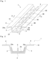
- a metal-resin composite 1 produced in the present embodiment includes a metal plate (metal member) 10 and a resin material 20.
- the metal-resin composite 1 has a hat shape in a cross section perpendicular to a longitudinal direction.
- the metal-resin composite 1 is formed by fixing the resin material 20 to an inner surface (recessed surface) of the metal plate 10 having a hat shape.
- the shape of the metal-resin composite 1 is not limited to a hat shape, and may be any shape.
- the metal-resin composite 1 includes a bottom wall portion 2 extending in the horizontal direction, side wall portions 3 rising from both ends of the bottom wall portion 2, and a flange portion 4 extending outward in the horizontal direction from the side wall portion 3.
- the bottom wall portion 2 includes the metal plate 10 and the resin material 20
- the side wall portion 3 includes the metal plate 10 and the resin material 20
- the flange portion 4 includes only the metal plate 10.
- the resin material 20 in the side wall portion 3 extends from the bottom wall portion 2 toward the flange portion 4 and terminates at an end surface 20a on the side wall portion 3.
- the resin material 20 has a first rib 5 extending in a longitudinal direction and second ribs 6A to 6E extending in a lateral direction.
- the first rib 5 is provided substantially at the center in the lateral direction of an upper surface of the resin material 20 of the bottom wall portion 2.
- the second ribs 6A to 6E are provided on the upper surface of the resin material 20 of the bottom wall portion 2 at substantially equal intervals in the longitudinal direction so as to connect the resin material 20 on the side wall portion 3 and the resin material 20 on the bottom wall portion 2.
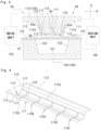
- the apparatus 50 for producing the metal-resin composite 1 in the present embodiment includes the mold set 80 including a mold 100, a drive unit 130 that drives the mold 100, and a heating unit 140 that heats the mold.
- the drive unit 130 and the heating unit 140 publicly-known units capable of executing press molding can be used, and details are not illustrated and a conceptual diagram is illustrated only in Fig. 3 , and illustration is omitted subsequent diagrams.
- the mold set 80 includes the mold 100 and a cap (molding auxiliary component) 90.
- the mold 100 is for press molding the metal plate 10 and the resin material 20 to produce the metal-resin composite 1.
- the mold 100 includes an upper mold 110 and a lower mold 120 that sandwich the metal plate 10 and the resin material 20.
- the upper mold 110 is configured as a punch
- the lower mold 120 is configured as a die.
- the upper mold 110 is movable in the vertical direction by the drive unit 130, that is, is configured to be capable of approaching and separating from the lower mold 120.
- a driving mode of the mold 100 by the drive unit 130 is not particularly limited, and the drive unit 130 may be one that moves at least one of the upper mold 110 and the lower mold 120 in the vertical direction.
- the upper mold 110 is configured as one member in the present embodiment, the upper mold 110 may be configured by two or more components such as a punch 110a and a holder 110b as in a variation illustrated in Fig. 8 .
- the upper mold 110 has a first molding upper surface 111 for molding the bottom wall portion 2 (see Fig. 2 ), a second molding upper surface 112 for molding the side wall portion 3 (see Fig. 2 ), and a third molding upper surface 113 for molding the flange portion 4 (see Fig. 2 ).
- the first molding upper surface 111 and the third molding upper surface 113 are configured as horizontal surfaces
- the second molding upper surface 112 is configured to connect the first molding upper surface 111 and the third molding upper surface 113 and to be inclined from the vertical direction.
- the upper mold 110 has a second press surface 117 for integrally molding the metal plate 10 and the resin material 20.
- the second press surface 117 includes the first molding upper surface 111, the second molding upper surface 112, and the third molding upper surface 113.
- a step 112a is provided on the second molding upper surface 112.
- the step 112a is provided so as to rise one step from the first molding upper surface 111 toward the third molding upper surface 113.
- the upper mold 110 is provided with a first groove portion 114 extending in the longitudinal direction and second groove portions 115A to 115E extending in the lateral direction.
- the first groove portion 114 is provided substantially at the center in the lateral direction of the first molding upper surface 111
- the second groove portions 115A to 115E are provided at substantially equal intervals in the longitudinal direction on the first molding upper surface 111 and the second molding upper surface 112.
- the lower mold 120 has a first molding lower surface 121 for molding the bottom wall portion 2 (see Fig. 2 ), a second molding lower surface 122 for molding the side wall portion 3 (see Fig. 2 ), and a third molding lower surface 123 for molding the flange portion 4 (see Fig. 2 ).
- the first molding lower surface 121 and the third molding lower surface 123 are configured as horizontal surfaces
- the second molding lower surface 122 is configured to connect the first molding lower surface 121 and the third molding lower surface 123 and to be inclined from the vertical direction.
- the first molding lower surface 121 is arranged to face the first molding upper surface 111
- the second molding lower surface 122 is arranged to face the second molding upper surface 112
- the third molding lower surface 123 is arranged to face the third molding upper surface 113.
- the cap 90 includes a plate-shaped cap bottom wall 91 and a cap side wall 92 rising from both ends of the cap bottom wall 91 and terminating at a cap end surface 92a.
- the cap 90 has a first press surface 97 for molding the metal plate 10.
- the first press surface 97 includes a lower surface 91b of the cap bottom wall 91 and an outer surface 92b of the cap side wall 92.
- a first protrusion 93 extending in the longitudinal direction is provided substantially at the center in the lateral direction of the upper surface 91a of the cap bottom wall 91.
- second protrusions 94A to 94E extending in the lateral direction are provided on the upper surface 91a of the cap bottom wall 91 at substantially equal intervals in the longitudinal direction.
- the material of the cap 90 is hard metal, but may be soft metal, resin, or the like. Further, in the present embodiment, the cap 90 is formed by cutting, but may be formed by another processing method such as casting or 3D printing.
- the cap 90 is attached to the upper mold 110 such that the upper surface 91a of the cap bottom wall 91 is in contact with the first molding upper surface 111, the outer surface 92b of the cap side wall 92 is in contact with the second molding upper surface 112, and the cap end surface 92a is in contact with the step 112a. Further, the cap 90 is attached to the upper mold 110 such that the first protrusion 93 is fitted into the first groove portion 114 and the second protrusions 94A to 94E are fitted into the second groove portions 115A to 115E. That is, the cap 90 is arranged so as to cover a corner portion 118 formed by the first molding upper surface 111 and the second molding upper surface 112. In the present embodiment, the cap 90 is fixed to the upper mold 110 so as to fill an entire cavity C (see Fig. 12 ) described later.
- the cap 90 is fixed to the upper mold 110 with a screw 150 that is a male screw.
- a screw 150 that is a male screw.
- through holes 95A to 95E penetrating from the lower surface 91b of the cap bottom wall 91 toward the upper mold 110 are provided at portions where the first protrusion 93 and the second protrusions 94A to 94E intersect.
- the upper mold 110 is provided with screw holes 116A to 116E which are female screws aligned with the through holes 95A to 95E.
- the cap 90 is fixed to the upper mold 110 by fastening the screw 150 to the screw holes 116A to 116E through the through holes 95A to 95E.
- a counterbore 96 having a diameter larger than that of the through holes 95A to 95E is provided on the lower surface 91b side of the through holes 95A to 95E, and when the screw 150 is fastened, a head portion of the screw 150 is housed in the counterbore 96 so as not to protrude from the lower surface 91b of the cap bottom wall 91.
- the cap 90 Since the cap 90 is fixed to the upper mold 110 with the screw 150, the cap 90 is removed from the upper mold 110 by removing the screw 150. That is, the cap 90 is detachably fixed to the upper mold 110.
- the cap 90 may be fixed to the upper mold 110 by adhesion using a double-sided tape or the like, or may be fixed by a magnetic force generated from a magnet embedded in the upper mold 110.
- a method for producing the metal-resin composite 1 in the present embodiment will be described with reference to Figs. 9 to 13 .
- the horizontal direction is indicated as an X direction
- the vertical direction is indicated as a Y direction.
- the metal-resin composite 1 (the metal plate 10 and the resin material 20) is hatched to indicate a cross section. However, hatching is omitted for other members for clarity of illustration.
- press molding is performed twice while first to fifth steps illustrated in Figs. 9 to 13 are executed sequentially.
- First pressing is executed in the first to third steps illustrated in Figs. 9 to 11
- second pressing is executed in the third to fifth steps illustrated in Figs. 11 to 13 .
- the upper mold 110 is lowered, and the metal plate 10 is sandwiched between the upper mold 110 to which the cap 90 is attached and the lower mold 120 and press molded into a hat shape.
- the metal plate 10 is mainly pressed toward the lower mold 120 by the first press surface 97.
- filling pressure of the resin material 20 in a subsequent step can be increased.
- the resin material 20 (see Figs.11 to 13 ) is not provided yet, and only metal plate 10 is sandwiched between upper mold 110 and lower mold 120 with the cap 90 interposed between them.
- the upper mold 110 is raised.
- the metal plate 10 is molded into a final shape (a hat shape in the present embodiment).
- the resin material 20 having a sheet-like shape (also referred to as prepreg) cut into a necessary size is placed on the metal plate 10.
- the resin material 20 is cured at a high temperature and a high pressure by a molding method called sheet molding compound (SMC) method (see the fourth step described later).
- SMC sheet molding compound
- the resin material 20 a fiber reinforced plastic (FRP) in which a glass fiber or a carbon fiber is impregnated into resin is used.
- the resin material 20 has a thermosetting property. In this step, the resin material 20 is not yet heated, that is, not cured. Note that the resin material 20 does not need to have a sheet-like shape, and can have any shape.
- the cap 90 is removed from the upper mold 110.
- the distances d1 and d21 (see Fig. 10 ) between the first press surface 97 and the lower mold 120 in a state where the cap 90 is attached are shorter than the distances d4 and d5 (see Fig. 12 ) between the second press surface 117 and the lower mold 120 in a state where the cap 90 is removed. More specifically, the distance d1 is shorter than the distance d4, and the distance d21 is shorter than the distance d5.
- a filling screw (not illustrated) is fastened to the screw holes 116A to 116E so that the resin material 20 does not enter the screw holes 116A to 116E of the upper mold 110, and the screw holes 116A to 116E are filled.
- a fourth step illustrated in Fig. 12 the upper mold 110 is lowered, and the metal plate 10 and the resin material 20 are sandwiched between the upper mold 110 and the lower mold 120 to be press molded so that the resin material 20 is fixed to the metal plate 10.
- the metal plate 10 and the resin material 20 are pressed against the lower mold 120 by the second press surface 117.
- the cavity C that is provided between the first and second molding upper surfaces 111 and 112 and the first and second molding lower surfaces 121 and 122 (specifically, the metal plate 10) is filled with the resin material 20. That is, the resin material 20 cut to a necessary size is put into the mold 100 and cured under high temperature and high pressure by the SMC method.
- the cavity C refers to a space below the step 112a formed by being sandwiched between the upper mold 110 and the lower mold 120 (specifically, the metal plate 10) and a space defined by the first groove portion 114 and the second groove portions 115A to 115E.
- the resin material 20 When the cavity C is filled with the resin material 20, the resin material 20 also flows into the first groove portion 114 and the second groove portions 115A to 115E of the upper mold 110, and the first rib 5 and the second ribs 6A to 6E (see Fig. 1 ) are formed.
- the cap 90 is arranged so as to fill the entire cavity C, and the entire cavity C is filled with the resin material 20. Therefore, as illustrated in Figs. 1 and 5 , the cap 90 and the resin material 20 in the metal-resin composite 1 have substantially the same shape.
- the upper mold 110 is raised.
- the resin material 20 is fixed to an upper surface (hat-shaped recessed surface) of the metal plate 10 and the metal-resin composite 1 is formed. In this way, the metal-resin composite 1 having a hat shape is produced as a product.
- the cavity C in which the resin material 20 is arranged is formed in a state where the upper mold 110 and the lower mold 120 are closed.
- the upper mold 110 cannot mold the metal plate 10 along the shape of a molding surface of the lower mold 120 in a location where the cavity C is formed.
- the cap 90 is attached to the upper mold 110 when the metal plate 10 is press molded, and then the cap 90 can be removed from the upper mold 110 when the metal-resin composite 1 is press molded.
- the distances d1 and d21 between the first press surface 97 and the lower mold 120 in a state where the cap 90 is attached are shorter than the distances d4 and d5 between the second press surface 117 and the lower mold 120 in a state where the cap 90 is removed. That is, since at least a part of the cavity C is filled with the cap 90 during the press molding of the metal plate 10, the cavity C is reduced, and the metal plate 10 easily follows the shape of the lower mold 120 during the press molding of the metal plate 10. As a result, molding accuracy of the metal plate 10 can be improved. Then, when the metal-resin composite 1 is press molded, the cavity C having a desired size and shape can be formed by removing the cap 90, so that the metal-resin composite 1 having a desired shape can be produced.
- the metal plate 10 easily follows the shape of the lower mold 120 at the time of press molding of the metal plate 10 since the cavity C does not exist. For this reason, molding accuracy of the metal plate 10 can be improved.
- the resin material 20 When the resin material 20 is provided in the fourth step, the resin material 20 needs to flow beyond the step 112a of the upper mold 110 in order to leak from the cavity C, and the cavity C can be sealed by the step 112a. Therefore, leakage of the resin material 20 can be suppressed. That is, the filling pressure of the resin material 20 in the cavity C can be increased, and the quality can be improved.
- the cap 90 Since the cap 90 is fixed to the upper mold 110 with the screw 150, the cap 90 can be mechanically firmly fixed to the upper mold 110. For this reason, detachment of the cap 90 from the upper mold 110 can be suppressed or prevented during press molding.
- the strength of the metal-resin composite 1 can be improved.
- the first groove portion 114 (see Fig. 4 ) and the second groove portions 115A to 115E (see Fig. 4 ) are not provided in the upper mold 110. Further, the cap 90 is not provided with the first protrusion 93 (see Fig. 5 ) or the second protrusions 94A to 94E (see Fig. 5 ).
- a magnet 160 is embedded in the upper mold 110.
- the present embodiment is substantially the same as the first embodiment except for these. Therefore, the description of a portion illustrated in the first embodiment may be omitted.
- the cap 90 has a substantially C-shaped plate shape, and has only the cap bottom wall 91 and the cap side wall 92.
- the cap 90 is formed by forming a metal plate. Note that the method of forming the cap 90 is not limited to bending, and can be formed by cutting, for example.
- the magnet 160 is embedded in the upper mold 110. For this reason, the cap 90 made from metal is fixed to the upper mold 110 by a magnetic force.
- the cap 90 is formed by bending a metal plate, processing is easy. That is, the number of manufacturing steps of the cap 90 can be reduced. Since the cap 90 is fixed to the upper mold 110 by the magnet 160, the cap 90 can be easily attached and detached.
- the upper mold 110 is provided with the first groove portion 114 and the second groove portions 115A to 115E (see Fig. 4 ). Further, the cap 90 is not provided with the first protrusion 93 (see Fig. 5 ) or the second protrusions 94A to 94E (see Fig. 5 ).
- the cap 90 can also be attached to the upper mold 110 to which the cap 90 illustrated in the first embodiment is attached.
- the caps 90 having different shapes can be attached to the common upper mold 110.
- the cap 90 includes corner caps 90a and 90b.
- the corner caps 90a and 90b are detachably fixed so as to fill a part of the cavity C (see Fig. 12 ).
- the corner caps 90a and 90b are arranged so as to cover only the corner portion 118 formed by the first molding upper surface 111 and the second molding upper surface 112 of the upper mold 110.
- the cap 90 is configured to fill only a part of the cavity C, the weight of the cap 90 is reduced, and the cap 90 can be easily attached and detached.
- the distance d1 (see Fig. 10 ) and the distance d21 (see Fig. 10 ) at the corner portion 118 are equal to the thickness t of the metal plate 10 when the metal plate 10 is press molded in the second step.
- the cavity C at the corner portion 118 is reduced.
- the metal plate 10 easily follows the shape of the lower mold 120 during the press molding of the metal plate 10, so that molding accuracy at the corner portion 118 of the metal plate 10 can be improved.
- the molding accuracy is required at the corner portion 118, it is effective to increase the dimensional accuracy by reducing the cavity C at the corner portion 118. Further, a straight portion where the metal plate 10 is not bent can be formed into a final shape by being press molded together with the resin material 20 in the fourth step. Therefore, the molding accuracy of the metal-resin composite 1 can be improved.
- an adhesive layer may be provided between the metal plate 10 and the resin material 20.
- the metal member 10 and the resin material 20 can be firmly integrally molded.
Landscapes
- Engineering & Computer Science (AREA)
- Mechanical Engineering (AREA)
- Chemical & Material Sciences (AREA)
- Composite Materials (AREA)
- Manufacturing & Machinery (AREA)
- Casting Or Compression Moulding Of Plastics Or The Like (AREA)
- Moulds For Moulding Plastics Or The Like (AREA)
Abstract
Molding accuracy of a metal member is improved in an apparatus, a mold set, and a method for producing a metal-resin composite with a set of molds. An apparatus 50 for manufacturing a metal-resin composite 1 by press molding a metal member 10 and a resin material 20, the apparatus 50 including a mold 100 including an upper mold 110 and a lower mold 120 sandwiching the metal member 10 and the resin material 20, a molding auxiliary component 90 detachably fixed to the upper mold 110 so as to fill at least a part of a cavity C for arranging the resin material 20 formed by the upper mold 110 and the lower mold 120, and a drive unit 130 that moves at least one of the upper mold 110 and the lower mold 120 in a vertical direction. The molding auxiliary component 90 has a first press surface 97 for molding the metal member 10. The upper mold 110 has a second press surface 117 for integrally molding the metal member 10 and the resin material 20. A distance between the first press surface 97 and the lower mold 120 in a state where the molding auxiliary component 90 is attached is shorter than a distance between the second press surface 117 and the lower mold 120 in a state where the molding auxiliary component 90 is removed.
Description
- The present invention relates to an apparatus, a mold set, and a method for producing a metal-resin composite.
- An apparatus for producing a metal-resin composite by press molding a metal member and a thermosetting resin material is known (for example, Patent Document 1). The metal-resin composite is integrally molded by press molding a metal member previously press molded by a press apparatus separate from the above apparatus and a resin material with the above apparatus. That is, in the production of the metal-resin composite, a mold for press molding a metal member and a mold for integrally molding the metal member and a resin material are used.
- Patent Document 1:
JP 2020-104411 A - In a case where the metal-resin composite is molded using a set of molds, a metal member is press molded into a predetermined shape, and then the metal member and a resin material are press molded using a mold used for the press molding of the metal member. In this case, since a cavity of the mold is designed in accordance with a shape of the metal-resin composite, that is, a final shape into which the metal member and the resin material are integrally molded, it is difficult to press mold the metal member along a lower mold, and molding accuracy of the metal member may be deteriorated.
- An object of the present invention is to improve molding accuracy of a metal member in an apparatus, a mold set, and a method for producing a metal-resin composite with a set of molds.
- A first aspect of the present invention provides an apparatus for producing a metal-resin composite by press molding a metal member and a resin material. The apparatus includes a mold including an upper mold and a lower mold that sandwich the metal member and the resin material, a molding auxiliary component detachably fixed to the upper mold so as to fill at least a part of a cavity for arranging the resin material formed by the upper mold and the lower mold, and a drive unit that moves at least one of the upper mold and the lower mold in a vertical direction. The molding auxiliary component has a first press surface for molding the metal member, and the upper mold has a second press surface for integrally molding the metal member and the resin material, and a distance between the first press surface and the lower mold in a state where the molding auxiliary component is attached is shorter than a distance between the second press surface and the lower mold in a state where the molding auxiliary component is removed.
- In a case where press molding of the metal member and integral molding of the metal member and the resin material are performed with a set of the molds, the cavity in which the resin material is arranged is formed in a state where the upper mold and the lower mold are closed. For this reason, during press molding of the metal member, the upper mold cannot mold the metal member along the shape of a molding surface of the lower mold in a location where the cavity is formed. In contrast, according to this configuration, first, the molding auxiliary component is attached to the upper mold when the metal member is press molded, and then the molding auxiliary component can be removed from the upper mold when the metal-resin composite is press molded. Further, a distance between the first press surface and the lower mold in a state where the molding auxiliary component is removed is shorter than a distance between the second press surface and the lower mold in a state where the molding auxiliary component is attached. That is, since at least a part of the cavity is filled with the molding auxiliary component during the press molding of the metal member, the cavity is reduced, and the metal member easily follows the shape of the lower mold during the press molding of the metal member. As a result, molding accuracy of the metal member can be improved. Then, when the metal-resin composite is press molded, the cavity having a desired size and shape can be formed by removing the molding auxiliary component, so that the metal-resin composite having a desired shape can be produced.
- The metal-resin composite may have, in a cross section perpendicular to a longitudinal direction, a bottom wall portion extending in a horizontal direction, side wall portions rising from both ends of the bottom wall portion, and a flange portion extending outward in the horizontal direction from the side wall portion, the upper mold may have, in the cross section, a first molding upper surface for molding the bottom wall portion, a second molding upper surface for molding the side wall portion, and a third molding upper surface for molding the flange portion, and the molding auxiliary component may be arranged so as to cover a corner portion formed by the first molding upper surface and the second molding upper surface.
- According to this configuration, the cavity at the corner portion is reduced. At a location where the cavity is reduced, the metal member easily follows the shape of the lower mold during press molding of the metal member, so that molding accuracy of the metal member can be improved. In particular, since the molding accuracy is required at the corner portion, it is effective to increase the dimensional accuracy by reducing the cavity at the corner portion.
- A step may be provided on the second molding upper surface.
- According to this configuration, since the resin material needs to flow beyond the step of the upper mold in order to leak out of the cavity, the cavity can be sealed by the step. Therefore, leakage of the resin material can be suppressed. That is, the filling pressure of the resin material in the cavity can be increased, and the quality can be improved.
- The molding auxiliary component may be detachably fixed to the upper mold so as to fill the entire cavity.
- According to this configuration, in a case where the upper mold and the lower mold are closed in a state where the molding auxiliary component is attached to the upper mold, the metal member easily follows the shape of the lower mold during press molding of the metal member because there is no cavity. For this reason, molding accuracy of the metal member can be improved.
- The molding auxiliary component may be provided with a through hole, the upper mold may be provided with a screw hole aligned with the through hole, and the molding auxiliary component may be fixed to the upper mold as a screw is fastened to the screw hole via the through hole.
- According to this configuration, the molding auxiliary component can be mechanically and firmly fixed to the upper mold. For this reason, detachment of the molding auxiliary component from the upper mold can be suppressed or prevented during press molding.
- A second aspect of the present invention provides a mold set for producing a metal-resin composite by press molding a metal member and a resin material. The mold set includes a mold including an upper mold and a lower mold that sandwich the metal member and the resin material, and a molding auxiliary component detachably fixed to the upper mold so as to fill at least a part of a cavity for arranging the resin material formed by the upper mold and the lower mold. The molding auxiliary component has a first press surface for molding the metal member, and the upper mold has a second press surface for integrally molding the metal member and the resin material, and a distance between the first press surface and the lower mold in a state where the molding auxiliary component is attached is shorter than a distance between the second press surface and the lower mold in a state where the molding auxiliary component is removed.
- In a case where press molding of the metal member and integral molding of the metal member and the resin material are performed with a set of the molds, the cavity in which the resin material is arranged is formed in a state where the upper mold and the lower mold are closed. For this reason, during press molding of the metal member, the upper mold cannot mold the metal member along the shape of a molding surface of the lower mold in a location where the cavity is formed. In contrast, according to this configuration, first, the molding auxiliary component is attached to the upper mold when the metal member is press molded, and then the molding auxiliary component can be removed from the upper mold when the metal-resin composite is press molded. In this manner, since at least a part of the cavity is filled with the molding auxiliary component during the press molding of the metal member, the cavity is reduced, and the metal member easily follows the shape of the lower mold during the press molding of the metal member. As a result, molding accuracy of the metal member can be improved. Then, when the metal-resin composite is press molded, the cavity having a desired size and shape can be formed by removing the molding auxiliary component, so that the metal-resin composite having a desired shape can be produced.
- A third aspect of the present invention provides a method for producing a metal-resin composite by press molding a metal member and a resin material. The method includes preparing a mold including an upper mold and a lower mold that sandwich the metal member and the resin material, and a molding auxiliary component detachably fixed to the upper mold so as to fill at least a part of a cavity for arranging the resin material formed by the upper mold and the lower mold, closing the upper mold to which the molding auxiliary component is attached and the lower mold to press mold the metal member, opening the upper mold to which the molding auxiliary component is attached and the lower mold to arrange the resin material on the metal member that is press molded, and closing the upper mold from which the molding auxiliary component is removed and the lower mold to integrally mold the metal member and the resin material.
- In a case where press molding of the metal member and integral molding of the metal member and the resin material are performed with a set of the molds, the cavity in which the resin material is arranged is formed in a state where the upper mold and the lower mold are closed. For this reason, during press molding of the metal member, the upper mold cannot mold the metal member along the shape of a molding surface of the lower mold in a location where the cavity is formed. In contrast, according to this configuration, since at least a part of the cavity is filled with the molding auxiliary component during the press molding of the metal member, the cavity is reduced, and the metal member easily follows the shape of the lower mold during the press molding of the metal member. As a result, molding accuracy of the metal member can be improved. Further, when the metal-resin composite is press molded, the cavity having a desired size and shape can be formed by removing the molding auxiliary component, so that the metal-resin composite having a desired shape can be produced.
- According to the present invention, in an apparatus, a mold set, and a method for producing a metal-resin composite with a set of molds, molding accuracy of a metal member can be improved.
-
Fig. 1 is a perspective view of a metal-resin composite according to a first embodiment of the present invention; -
Fig. 2 is a cross-sectional view taken along line II-II inFig. 1 ; -
Fig. 3 is a schematic diagram of an apparatus according to the first embodiment of the present invention; -
Fig. 4 is a perspective view of an upper mold according to the first embodiment of the present invention; -
Fig. 5 is a perspective view of a molding auxiliary component according to the first embodiment of the present invention; -
Fig. 6 is a perspective view of the upper mold and the molding auxiliary component according to the first embodiment of the present invention; -
Fig. 7 is a cross-sectional view taken along line VII-VII inFig. 6 ; -
Fig. 8 is a cross-sectional view similar toFig. 7 , illustrating a variation of the first embodiment of the present invention; -
Fig. 9 is a cross-sectional view illustrating a first step of a method for producing the metal-resin composite in the first embodiment; -
Fig. 10 is a cross-sectional view illustrating a second step of the method for producing the metal-resin composite in the first embodiment; -
Fig. 11 is a cross-sectional view illustrating a third step of the method for producing the metal-resin composite in the first embodiment; -
Fig. 12 is a cross-sectional view illustrating a fourth step of the method for producing the metal-resin composite in the first embodiment; -
Fig. 13 is a cross-sectional view illustrating a fifth step of the method for producing the metal-resin composite in the first embodiment; -
Fig. 14 is a cross-sectional view taken along line XIV-XIV inFig. 6 in a second embodiment of the present invention; -
Fig. 15 is a cross-sectional view similar toFig. 14 illustrating a variation of the second embodiment of the present invention; and -
Fig. 16 is a cross-sectional view similar toFig. 14 illustrating a variation of the second embodiment of the present invention. - Hereinafter, an apparatus, a mold set, and a method for producing a metal-resin composite will be described as an embodiment of the present invention with reference to the accompanying drawings.
- Referring to
Figs. 1 and 2 , a metal-resin composite 1 produced in the present embodiment includes a metal plate (metal member) 10 and aresin material 20. As illustrated inFig. 2 , the metal-resin composite 1 has a hat shape in a cross section perpendicular to a longitudinal direction. Specifically, the metal-resin composite 1 is formed by fixing theresin material 20 to an inner surface (recessed surface) of themetal plate 10 having a hat shape. However, the shape of the metal-resin composite 1 is not limited to a hat shape, and may be any shape. - The metal-
resin composite 1 includes abottom wall portion 2 extending in the horizontal direction,side wall portions 3 rising from both ends of thebottom wall portion 2, and aflange portion 4 extending outward in the horizontal direction from theside wall portion 3. Thebottom wall portion 2 includes themetal plate 10 and theresin material 20, theside wall portion 3 includes themetal plate 10 and theresin material 20, and theflange portion 4 includes only themetal plate 10. In the present embodiment, theresin material 20 in theside wall portion 3 extends from thebottom wall portion 2 toward theflange portion 4 and terminates at anend surface 20a on theside wall portion 3. - As illustrated in
Fig. 1 , in the present embodiment, theresin material 20 has afirst rib 5 extending in a longitudinal direction andsecond ribs 6A to 6E extending in a lateral direction. Specifically, thefirst rib 5 is provided substantially at the center in the lateral direction of an upper surface of theresin material 20 of thebottom wall portion 2. Thesecond ribs 6A to 6E are provided on the upper surface of theresin material 20 of thebottom wall portion 2 at substantially equal intervals in the longitudinal direction so as to connect theresin material 20 on theside wall portion 3 and theresin material 20 on thebottom wall portion 2. - An
apparatus 50 and a mold set 80 for producing the metal-resin composite 1 in the present embodiment will be described with reference toFigs. 3 to 8 . - Referring to
Fig. 3 , theapparatus 50 for producing the metal-resin composite 1 in the present embodiment includes the mold set 80 including amold 100, adrive unit 130 that drives themold 100, and aheating unit 140 that heats the mold. Note that, as thedrive unit 130 and theheating unit 140, publicly-known units capable of executing press molding can be used, and details are not illustrated and a conceptual diagram is illustrated only inFig. 3 , and illustration is omitted subsequent diagrams. - The mold set 80 includes the
mold 100 and a cap (molding auxiliary component) 90. - The
mold 100 is for press molding themetal plate 10 and theresin material 20 to produce the metal-resin composite 1. Themold 100 includes anupper mold 110 and alower mold 120 that sandwich themetal plate 10 and theresin material 20. In the present embodiment, theupper mold 110 is configured as a punch, and thelower mold 120 is configured as a die. Theupper mold 110 is movable in the vertical direction by thedrive unit 130, that is, is configured to be capable of approaching and separating from thelower mold 120. However, a driving mode of themold 100 by thedrive unit 130 is not particularly limited, and thedrive unit 130 may be one that moves at least one of theupper mold 110 and thelower mold 120 in the vertical direction. Further, although theupper mold 110 is configured as one member in the present embodiment, theupper mold 110 may be configured by two or more components such as apunch 110a and aholder 110b as in a variation illustrated inFig. 8 . - Referring to
Figs. 3 and 4 , theupper mold 110 has a first moldingupper surface 111 for molding the bottom wall portion 2 (seeFig. 2 ), a second moldingupper surface 112 for molding the side wall portion 3 (seeFig. 2 ), and a third moldingupper surface 113 for molding the flange portion 4 (seeFig. 2 ). In the present embodiment, the first moldingupper surface 111 and the third moldingupper surface 113 are configured as horizontal surfaces, and the second moldingupper surface 112 is configured to connect the first moldingupper surface 111 and the third moldingupper surface 113 and to be inclined from the vertical direction. As will be described in detail later, theupper mold 110 has asecond press surface 117 for integrally molding themetal plate 10 and theresin material 20. In the present embodiment, thesecond press surface 117 includes the first moldingupper surface 111, the second moldingupper surface 112, and the third moldingupper surface 113. - In the present embodiment, a
step 112a is provided on the second moldingupper surface 112. Thestep 112a is provided so as to rise one step from the first moldingupper surface 111 toward the third moldingupper surface 113. - In the present embodiment, the
upper mold 110 is provided with afirst groove portion 114 extending in the longitudinal direction andsecond groove portions 115A to 115E extending in the lateral direction. Specifically, thefirst groove portion 114 is provided substantially at the center in the lateral direction of the first moldingupper surface 111, and thesecond groove portions 115A to 115E are provided at substantially equal intervals in the longitudinal direction on the first moldingupper surface 111 and the second moldingupper surface 112. - Referring to
Fig. 3 , thelower mold 120 has a first moldinglower surface 121 for molding the bottom wall portion 2 (seeFig. 2 ), a second moldinglower surface 122 for molding the side wall portion 3 (seeFig. 2 ), and a third moldinglower surface 123 for molding the flange portion 4 (seeFig. 2 ). In the present embodiment, the first moldinglower surface 121 and the third moldinglower surface 123 are configured as horizontal surfaces, and the second moldinglower surface 122 is configured to connect the first moldinglower surface 121 and the third moldinglower surface 123 and to be inclined from the vertical direction. The first moldinglower surface 121 is arranged to face the first moldingupper surface 111, the second moldinglower surface 122 is arranged to face the second moldingupper surface 112, and the third moldinglower surface 123 is arranged to face the third moldingupper surface 113. - Referring also to
Fig. 5 , thecap 90 includes a plate-shaped capbottom wall 91 and acap side wall 92 rising from both ends of thecap bottom wall 91 and terminating at acap end surface 92a. As will be described in detail later, thecap 90 has afirst press surface 97 for molding themetal plate 10. In the present .embodiment, thefirst press surface 97 includes alower surface 91b of thecap bottom wall 91 and anouter surface 92b of thecap side wall 92. - Further, in the
cap 90, afirst protrusion 93 extending in the longitudinal direction is provided substantially at the center in the lateral direction of theupper surface 91a of thecap bottom wall 91. Furthermore, in thecap 90,second protrusions 94A to 94E extending in the lateral direction are provided on theupper surface 91a of thecap bottom wall 91 at substantially equal intervals in the longitudinal direction. - In the present embodiment, the material of the
cap 90 is hard metal, but may be soft metal, resin, or the like. Further, in the present embodiment, thecap 90 is formed by cutting, but may be formed by another processing method such as casting or 3D printing. - Referring to
Figs. 3 and6 , thecap 90 is attached to theupper mold 110 such that theupper surface 91a of thecap bottom wall 91 is in contact with the first moldingupper surface 111, theouter surface 92b of thecap side wall 92 is in contact with the second moldingupper surface 112, and thecap end surface 92a is in contact with thestep 112a. Further, thecap 90 is attached to theupper mold 110 such that thefirst protrusion 93 is fitted into thefirst groove portion 114 and thesecond protrusions 94A to 94E are fitted into thesecond groove portions 115A to 115E. That is, thecap 90 is arranged so as to cover acorner portion 118 formed by the first moldingupper surface 111 and the second moldingupper surface 112. In the present embodiment, thecap 90 is fixed to theupper mold 110 so as to fill an entire cavity C (seeFig. 12 ) described later. - Referring to
Figs. 6 and7 , in the present embodiment, thecap 90 is fixed to theupper mold 110 with ascrew 150 that is a male screw. Specifically, throughholes 95A to 95E penetrating from thelower surface 91b of thecap bottom wall 91 toward theupper mold 110 are provided at portions where thefirst protrusion 93 and thesecond protrusions 94A to 94E intersect. Further, theupper mold 110 is provided withscrew holes 116A to 116E which are female screws aligned with the throughholes 95A to 95E. Thecap 90 is fixed to theupper mold 110 by fastening thescrew 150 to the screw holes 116A to 116E through the throughholes 95A to 95E. - Further, a
counterbore 96 having a diameter larger than that of the throughholes 95A to 95E is provided on thelower surface 91b side of the throughholes 95A to 95E, and when thescrew 150 is fastened, a head portion of thescrew 150 is housed in thecounterbore 96 so as not to protrude from thelower surface 91b of thecap bottom wall 91. - Since the
cap 90 is fixed to theupper mold 110 with thescrew 150, thecap 90 is removed from theupper mold 110 by removing thescrew 150. That is, thecap 90 is detachably fixed to theupper mold 110. Thecap 90 may be fixed to theupper mold 110 by adhesion using a double-sided tape or the like, or may be fixed by a magnetic force generated from a magnet embedded in theupper mold 110. - A method for producing the metal-
resin composite 1 in the present embodiment will be described with reference toFigs. 9 to 13 . In the drawings, the horizontal direction is indicated as an X direction, and the vertical direction is indicated as a Y direction. Further, the metal-resin composite 1 (themetal plate 10 and the resin material 20) is hatched to indicate a cross section. However, hatching is omitted for other members for clarity of illustration. - In the present embodiment, press molding is performed twice while first to fifth steps illustrated in
Figs. 9 to 13 are executed sequentially. First pressing is executed in the first to third steps illustrated inFigs. 9 to 11 , and second pressing is executed in the third to fifth steps illustrated inFigs. 11 to 13 . - In the first step illustrated in
Fig. 9 , in a state where thecap 90 attached to theupper mold 110, themetal plate 10 having a flat plate shape before molding is placed on thelower mold 120. - In the second step illustrated in
Fig. 10 , theupper mold 110 is lowered, and themetal plate 10 is sandwiched between theupper mold 110 to which thecap 90 is attached and thelower mold 120 and press molded into a hat shape. At this time, themetal plate 10 is mainly pressed toward thelower mold 120 by thefirst press surface 97. In a state where theupper mold 110 and thelower mold 120 are closed, a distance d1 between thelower surface 91b of thecap bottom wall 91 and the first moldinglower surface 121 is substantially equal to a thickness t of the metal plate 10 (d1 = t). By setting the distance d1 equal to the thickness t of themetal plate 10, the molding accuracy of themetal plate 10 can be improved. Further, a distance d3 between the third moldingupper surface 113 and the third moldinglower surface 123 is substantially equal to the thickness t of the metal plate 10 (d3 = t). Further, a distance d21 between theouter surface 92b of thecap side wall 92 and the second moldinglower surface 122 below thestep 112a is substantially equal to or slightly larger than the thickness t of the metal plate 10 (d21 = t or d21 > t). Further, a distance d22 between the second moldingupper surface 112 and the second moldinglower surface 122 above thestep 112a is substantially equal to or slightly larger than the thickness t of the metal plate 10 (d22 = t or d22 > t). In particular, by setting the distance d22 equal to the thickness t of themetal plate 10, filling pressure of theresin material 20 in a subsequent step can be increased. Note that, in this step, the resin material 20 (seeFigs.11 to 13 ) is not provided yet, and onlymetal plate 10 is sandwiched betweenupper mold 110 andlower mold 120 with thecap 90 interposed between them. - In the third step illustrated in
Fig. 11 , theupper mold 110 is raised. At this time, themetal plate 10 is molded into a final shape (a hat shape in the present embodiment). Then, theresin material 20 having a sheet-like shape (also referred to as prepreg) cut into a necessary size is placed on themetal plate 10. In the present embodiment, theresin material 20 is cured at a high temperature and a high pressure by a molding method called sheet molding compound (SMC) method (see the fourth step described later). In the present embodiment, as theresin material 20, a fiber reinforced plastic (FRP) in which a glass fiber or a carbon fiber is impregnated into resin is used. Further, in the present embodiment, theresin material 20 has a thermosetting property. In this step, theresin material 20 is not yet heated, that is, not cured. Note that theresin material 20 does not need to have a sheet-like shape, and can have any shape. - Further, in the third step, the
cap 90 is removed from theupper mold 110. The distances d1 and d21 (seeFig. 10 ) between thefirst press surface 97 and thelower mold 120 in a state where thecap 90 is attached are shorter than the distances d4 and d5 (seeFig. 12 ) between thesecond press surface 117 and thelower mold 120 in a state where thecap 90 is removed. More specifically, the distance d1 is shorter than the distance d4, and the distance d21 is shorter than the distance d5. After thecap 90 is removed, a filling screw (not illustrated) is fastened to the screw holes 116A to 116E so that theresin material 20 does not enter the screw holes 116A to 116E of theupper mold 110, and the screw holes 116A to 116E are filled. - In a fourth step illustrated in
Fig. 12 , theupper mold 110 is lowered, and themetal plate 10 and theresin material 20 are sandwiched between theupper mold 110 and thelower mold 120 to be press molded so that theresin material 20 is fixed to themetal plate 10. At this time, themetal plate 10 and theresin material 20 are pressed against thelower mold 120 by thesecond press surface 117. The cavity C that is provided between the first and second moldingupper surfaces lower surfaces 121 and 122 (specifically, the metal plate 10) is filled with theresin material 20. That is, theresin material 20 cut to a necessary size is put into themold 100 and cured under high temperature and high pressure by the SMC method. In the present embodiment, the cavity C refers to a space below thestep 112a formed by being sandwiched between theupper mold 110 and the lower mold 120 (specifically, the metal plate 10) and a space defined by thefirst groove portion 114 and thesecond groove portions 115A to 115E. - When the cavity C is filled with the
resin material 20, theresin material 20 also flows into thefirst groove portion 114 and thesecond groove portions 115A to 115E of theupper mold 110, and thefirst rib 5 and thesecond ribs 6A to 6E (seeFig. 1 ) are formed. Note that, in the present embodiment, thecap 90 is arranged so as to fill the entire cavity C, and the entire cavity C is filled with theresin material 20. Therefore, as illustrated inFigs. 1 and5 , thecap 90 and theresin material 20 in the metal-resin composite 1 have substantially the same shape. - In the fifth step illustrated in
Fig. 13 , theupper mold 110 is raised. Theresin material 20 is fixed to an upper surface (hat-shaped recessed surface) of themetal plate 10 and the metal-resin composite 1 is formed. In this way, the metal-resin composite 1 having a hat shape is produced as a product. - In a case where press molding of the
metal plate 10 and integral molding of themetal plate 10 and theresin material 20 are performed with a set of themolds 100, the cavity C in which theresin material 20 is arranged is formed in a state where theupper mold 110 and thelower mold 120 are closed. For this reason, during press molding of themetal plate 10, theupper mold 110 cannot mold themetal plate 10 along the shape of a molding surface of thelower mold 120 in a location where the cavity C is formed. In contrast, according to the present embodiment, first, thecap 90 is attached to theupper mold 110 when themetal plate 10 is press molded, and then thecap 90 can be removed from theupper mold 110 when the metal-resin composite 1 is press molded. Further, the distances d1 and d21 between thefirst press surface 97 and thelower mold 120 in a state where thecap 90 is attached are shorter than the distances d4 and d5 between thesecond press surface 117 and thelower mold 120 in a state where thecap 90 is removed. That is, since at least a part of the cavity C is filled with thecap 90 during the press molding of themetal plate 10, the cavity C is reduced, and themetal plate 10 easily follows the shape of thelower mold 120 during the press molding of themetal plate 10. As a result, molding accuracy of themetal plate 10 can be improved. Then, when the metal-resin composite 1 is press molded, the cavity C having a desired size and shape can be formed by removing thecap 90, so that the metal-resin composite 1 having a desired shape can be produced. - Further, in a case where the
upper mold 110 and thelower mold 120 are closed in a state where thecap 90 is attached to theupper mold 110, themetal plate 10 easily follows the shape of thelower mold 120 at the time of press molding of themetal plate 10 since the cavity C does not exist. For this reason, molding accuracy of themetal plate 10 can be improved. - When the
resin material 20 is provided in the fourth step, theresin material 20 needs to flow beyond thestep 112a of theupper mold 110 in order to leak from the cavity C, and the cavity C can be sealed by thestep 112a. Therefore, leakage of theresin material 20 can be suppressed. That is, the filling pressure of theresin material 20 in the cavity C can be increased, and the quality can be improved. - Since the
cap 90 is fixed to theupper mold 110 with thescrew 150, thecap 90 can be mechanically firmly fixed to theupper mold 110. For this reason, detachment of thecap 90 from theupper mold 110 can be suppressed or prevented during press molding. - In the metal-
resin composite 1 in the present embodiment, since thefirst rib 5 and thesecond ribs 6A to 6B are molded, the strength of the metal-resin composite 1 can be improved. - In the second embodiment illustrated in
Fig. 14 , the first groove portion 114 (seeFig. 4 ) and thesecond groove portions 115A to 115E (seeFig. 4 ) are not provided in theupper mold 110. Further, thecap 90 is not provided with the first protrusion 93 (seeFig. 5 ) or thesecond protrusions 94A to 94E (seeFig. 5 ). - Furthermore, a
magnet 160 is embedded in theupper mold 110. The present embodiment is substantially the same as the first embodiment except for these. Therefore, the description of a portion illustrated in the first embodiment may be omitted. - In the second embodiment, the
cap 90 has a substantially C-shaped plate shape, and has only thecap bottom wall 91 and thecap side wall 92. Thecap 90 is formed by forming a metal plate. Note that the method of forming thecap 90 is not limited to bending, and can be formed by cutting, for example. - The
magnet 160 is embedded in theupper mold 110. For this reason, thecap 90 made from metal is fixed to theupper mold 110 by a magnetic force. - In the second embodiment, since the
cap 90 is formed by bending a metal plate, processing is easy. That is, the number of manufacturing steps of thecap 90 can be reduced. Since thecap 90 is fixed to theupper mold 110 by themagnet 160, thecap 90 can be easily attached and detached. - Referring to
Fig. 15 , in a variation of the second embodiment, as shown in the first embodiment, theupper mold 110 is provided with thefirst groove portion 114 and thesecond groove portions 115A to 115E (seeFig. 4 ). Further, thecap 90 is not provided with the first protrusion 93 (seeFig. 5 ) or thesecond protrusions 94A to 94E (seeFig. 5 ). - In the present variation, the
cap 90 can also be attached to theupper mold 110 to which thecap 90 illustrated in the first embodiment is attached. In other words, thecaps 90 having different shapes can be attached to the commonupper mold 110. - Referring to
Fig. 16 , in a variation of the second embodiment, thecap 90 includes corner caps 90a and 90b. The corner caps 90a and 90b are detachably fixed so as to fill a part of the cavity C (seeFig. 12 ). Specifically, the corner caps 90a and 90b are arranged so as to cover only thecorner portion 118 formed by the first moldingupper surface 111 and the second moldingupper surface 112 of theupper mold 110. - Since the
cap 90 is configured to fill only a part of the cavity C, the weight of thecap 90 is reduced, and thecap 90 can be easily attached and detached. - Further, since the
cap 90 is attached to thecorner portion 118 formed by the first moldingupper surface 111 and the second moldingupper surface 112, the distance d1 (seeFig. 10 ) and the distance d21 (seeFig. 10 ) at thecorner portion 118 are equal to the thickness t of themetal plate 10 when themetal plate 10 is press molded in the second step. In other words, the cavity C at thecorner portion 118 is reduced. At a location where the cavity C is reduced, themetal plate 10 easily follows the shape of thelower mold 120 during the press molding of themetal plate 10, so that molding accuracy at thecorner portion 118 of themetal plate 10 can be improved. In particular, since the molding accuracy is required at thecorner portion 118, it is effective to increase the dimensional accuracy by reducing the cavity C at thecorner portion 118. Further, a straight portion where themetal plate 10 is not bent can be formed into a final shape by being press molded together with theresin material 20 in the fourth step. Therefore, the molding accuracy of the metal-resin composite 1 can be improved. - In the metal-
resin composite 1, an adhesive layer may be provided between themetal plate 10 and theresin material 20. In this case, by providing the adhesive layer, themetal member 10 and theresin material 20 can be firmly integrally molded.
Claims (7)
- An apparatus (50) for producing a metal-resin composite (1) by press molding a metal member (10) and a resin material (20), the apparatus (50) comprising:a mold (100) including an upper mold (110) and a lower mold (120) that sandwich the metal member (10) and the resin material (20);a molding auxiliary component (90) detachably fixed to the upper mold (110) so as to fill at least a part of a cavity (C) for arranging the resin material (20) formed by the upper mold (110) and the lower mold (120); anda drive unit (130) that moves at least one of the upper mold (110) and the lower mold (120) in a vertical direction, whereinthe molding auxiliary component (90) has a first press surface (97) for molding the metal member (10),the upper mold (110) has a second press surface (117) for integrally molding the metal member (10) and the resin material (20), anda distance between the first press surface (97) and the lower mold (120) in a state where the molding auxiliary component (90) is attached is shorter than a distance between the second press surface (117) and the lower mold (130) in a state where the molding auxiliary component (90) is removed.
- The apparatus (50) according claim 1, whereinthe metal-resin composite (1) has, in a cross section perpendicular to a longitudinal direction, a bottom wall portion (2) extending in a horizontal direction, side wall portions (3) rising from both ends of the bottom wall portion (2), and a flange portion (4) extending outward in the horizontal direction from the side wall portion (3),the upper mold (110) has, in the cross section, a first molding upper surface (111) for molding the bottom wall portion (2), a second molding upper surface (112) for molding the side wall portion (3), and a third molding upper surface (113) for molding the flange portion (4), andthe molding auxiliary component (90) is arranged so as to cover a corner portion (118) formed by the first molding upper surface (111) and the second molding upper surface (112).
- The apparatus (50) according to claim 2, wherein the second molding upper surface (112) is provided with a step (112a) .
- The apparatus (50) according to any of claims 1 to 3, wherein the molding auxiliary component (90) is detachably fixed to the upper mold (110) so as to fill the entire cavity (C).
- The apparatus (50) according to any of claims 1 to 4, whereinthe molding auxiliary component (90) is provided with a through hole(95A-95E),the upper mold is provided with a screw hole(116A-116E) aligned with the through hole (95A-95E), andthe molding auxiliary component (90) is fixed to the upper mold (110) as a screw is fastened to the screw hole (116A-116E) via the through hole (95A-95E).
- A mold set for producing a metal-resin composite (1) by press molding a metal member (10) and a resin material (20), the mold set comprising:a mold (100) including an upper mold (110) and a lower mold (120) that sandwich the metal member (10) and the resin material (20); anda molding auxiliary component (90) detachably fixed to the upper mold (110) so as to fill at least a part of a cavity (C) for arranging the resin material (20) formed by the upper mold (110) and the lower mold (120), whereinthe molding auxiliary component (90) has a first press surface (97) for molding the metal member (10),the upper mold (110) has a second press surface (117) for integrally molding the metal member (10) and the resin material (20), anda distance between the first press surface (97) and the lower mold (120) in a state where the molding auxiliary component (90) is attached is shorter than a distance between the second press surface (117) and the lower mold (120) in a state where the molding auxiliary component (90) is removed.
- A method for producing a metal-resin composite (1) by press molding a metal member (10) and a resin material (20), the method comprising:preparing a mold (100) including an upper mold (110) and a lower mold (120) that sandwich the metal member (10) and the resin material (20), and a molding auxiliary component (90) detachably fixed to the upper mold (110) so as to fill at least a part of a cavity (C) for arranging the resin material (20) formed by the upper mold (110) and the lower mold (120);closing the upper mold (110) to which the molding auxiliary component (90) is attached and the lower mold (120) to press mold the metal member (10);opening the upper mold (110) to which the molding auxiliary component (90) is attached and the lower mold (120) to arrange the resin material (20) on the metal member (10) that is press molded; andclosing the upper mold (110) from which the molding auxiliary component (90) is removed and the lower mold (120) to integrally mold the metal member (10) and the resin material (20).
Applications Claiming Priority (1)
| Application Number | Priority Date | Filing Date | Title |
|---|---|---|---|
| JP2021166372A JP7560059B2 (en) | 2021-10-08 | 2021-10-08 | Apparatus, die set, and method for manufacturing metal-resin composite |
Publications (1)
| Publication Number | Publication Date |
|---|---|
| EP4163081A1 true EP4163081A1 (en) | 2023-04-12 |
Family
ID=84330657
Family Applications (1)
| Application Number | Title | Priority Date | Filing Date |
|---|---|---|---|
| EP22199850.3A Pending EP4163081A1 (en) | 2021-10-08 | 2022-10-05 | Apparatus, mold set, and method for producing metal-resin composite |
Country Status (4)
| Country | Link |
|---|---|
| US (1) | US12059827B2 (en) |
| EP (1) | EP4163081A1 (en) |
| JP (1) | JP7560059B2 (en) |
| CN (1) | CN115958734A (en) |
Families Citing this family (2)
| Publication number | Priority date | Publication date | Assignee | Title |
|---|---|---|---|---|
| JP2025017051A (en) * | 2023-07-24 | 2025-02-05 | 株式会社神戸製鋼所 | Metal-resin composite and its manufacturing method |
| JP2025019842A (en) * | 2023-07-28 | 2025-02-07 | 株式会社神戸製鋼所 | Metal-resin composite and its manufacturing method |
Citations (3)
| Publication number | Priority date | Publication date | Assignee | Title |
|---|---|---|---|---|
| DE102013109616A1 (en) * | 2013-09-03 | 2015-03-05 | Thyssenkrupp Steel Europe Ag | Semi-finished product and method for producing a three-dimensionally shaped hybrid component in the metal / plastic composite and use of such a semi-finished product |
| WO2015034119A1 (en) * | 2013-09-09 | 2015-03-12 | Lee Hwan Gil | Injection molding method, injection mold, and material injected by same |
| JP2020104411A (en) | 2018-12-27 | 2020-07-09 | 豊田鉄工株式会社 | Hot press machine and method for molding metal-resin composite |
Family Cites Families (13)
| Publication number | Priority date | Publication date | Assignee | Title |
|---|---|---|---|---|
| AT377228B (en) * | 1980-07-24 | 1985-02-25 | Lignotock Verfahrenstech | METHOD AND DEVICE FOR MANUFACTURING MOLDED PARTS FROM LEVEL FLOORED MESH FIBER MATS, PREFERABLY FROM CELLULOSE OR LIGNOCELLULOSE FIBERS PROVIDED WITH BINDERS |
| US20040096535A1 (en) * | 2002-11-15 | 2004-05-20 | Hudecek Robert W. | Compression molding apparatus having replaceable mold inserts |
| JP4540049B2 (en) * | 2004-09-28 | 2010-09-08 | 大和製罐株式会社 | Method for manufacturing metal cap with sealing liner |
| DE102011050701A1 (en) * | 2011-05-30 | 2012-12-06 | Benteler Automobiltechnik Gmbh | Method for producing a hybrid component and cover for use in the manufacture |
| JP5919066B2 (en) | 2012-03-30 | 2016-05-18 | 富士重工業株式会社 | Monolithic molded part manufacturing method and monolithic molded part |
| CN105073389B (en) * | 2013-03-13 | 2018-04-03 | 爱信高丘株式会社 | Composite structure of fiber-reinforced plastic plate and metal plate and manufacturing method thereof |
| EP2886287A1 (en) * | 2013-12-20 | 2015-06-24 | nolax AG | Method for producing hybrid components |
| CN203901602U (en) * | 2014-06-20 | 2014-10-29 | 林东生 | Integrated molding device for silica gel and sheet steel in sealing gasket of tablet computer |
| JP6303053B1 (en) * | 2017-07-26 | 2018-03-28 | 株式会社The MOT Company | Method for producing metal-fiber reinforced resin composite molded body |
| JP6876637B2 (en) * | 2018-01-22 | 2021-05-26 | Towa株式会社 | Molding mold, resin molding equipment and manufacturing method of resin molded products |
| US12134218B2 (en) * | 2018-05-24 | 2024-11-05 | Nissan Motor Co., Ltd. | Method of forming component using metal-resin composite and mold for forming said component |
| JP7249932B2 (en) * | 2019-12-10 | 2023-03-31 | 豊田鉄工株式会社 | Heat press device and molding method for metal-resin composite |
| JP2022189011A (en) * | 2021-06-10 | 2022-12-22 | 株式会社神戸製鋼所 | Mold, apparatus and method for manufacturing metal-resin composite |
-
2021
- 2021-10-08 JP JP2021166372A patent/JP7560059B2/en active Active
-
2022
- 2022-09-22 US US17/934,384 patent/US12059827B2/en active Active
- 2022-09-30 CN CN202211206512.4A patent/CN115958734A/en active Pending
- 2022-10-05 EP EP22199850.3A patent/EP4163081A1/en active Pending
Patent Citations (3)
| Publication number | Priority date | Publication date | Assignee | Title |
|---|---|---|---|---|
| DE102013109616A1 (en) * | 2013-09-03 | 2015-03-05 | Thyssenkrupp Steel Europe Ag | Semi-finished product and method for producing a three-dimensionally shaped hybrid component in the metal / plastic composite and use of such a semi-finished product |
| WO2015034119A1 (en) * | 2013-09-09 | 2015-03-12 | Lee Hwan Gil | Injection molding method, injection mold, and material injected by same |
| JP2020104411A (en) | 2018-12-27 | 2020-07-09 | 豊田鉄工株式会社 | Hot press machine and method for molding metal-resin composite |
Also Published As
| Publication number | Publication date |
|---|---|
| CN115958734A (en) | 2023-04-14 |
| US20230111000A1 (en) | 2023-04-13 |
| JP2023056889A (en) | 2023-04-20 |
| US12059827B2 (en) | 2024-08-13 |
| JP7560059B2 (en) | 2024-10-02 |
Similar Documents
| Publication | Publication Date | Title |
|---|---|---|
| JP6563284B2 (en) | Manufacturing apparatus for fiber-reinforced plastic molded product and manufacturing method thereof | |
| US12059827B2 (en) | Apparatus, mold set, and method for producing metal-resin composite | |
| CN101489769B (en) | Composite Manufacturing Method | |
| JP6401413B1 (en) | Method for producing metal-fiber reinforced resin composite molded body | |
| JP2011011473A (en) | Method for molding wing structure | |
| CN110431002B (en) | Composite material member, method for producing composite material member, and mold for forming the same | |
| JP2014237243A (en) | Apparatus and method for production of fiber-reinforced plastic structure | |
| US20220395885A1 (en) | Mold, apparatus, and method for producing metal-resin composite | |
| US20220396041A1 (en) | Mold, apparatus, and method for producing metal-resin composite | |
| WO2017068812A1 (en) | Method for manufacturing fiber-reinforced resin structure, system for manufacturing fiber-reinforced resin structure, and fiber-reinforced resin structure | |
| JP6573308B2 (en) | Manufacturing method of fiber reinforced resin structure | |
| EP4101615A1 (en) | Apparatus and method for producing metal-resin composite | |
| US9579853B2 (en) | Method for making a molded composite article | |
| US12377612B2 (en) | Apparatus and method for manufacturing metal-resin composite | |
| US12594742B2 (en) | Metal-resin composite and method and apparatus for manufacturing the same | |
| JP7755551B2 (en) | Metal-resin composite and method and apparatus for manufacturing the same | |
| US20240083120A1 (en) | Hot-Pressing Molding Method for Fiber Thermosetting Prepreg Material | |
| EP4063107A1 (en) | Fiber reinforced composite material molding method and fiber reinforced composite material molding apparatus | |
| JP2019171740A (en) | Apparatus for manufacturing fiber-reinforced molded body and method for manufacturing fiber-reinforced molded product | |
| US20210170646A1 (en) | Hybrid part made of composite material comprising at least one metal insert and method for manufacturing such a part | |
| JP4557882B2 (en) | Inductor for electromagnetic forming and manufacturing method thereof | |
| JP6213357B2 (en) | Method for producing resin frame for fuel cell | |
| JP2022189013A (en) | Apparatus and method for manufacturing metal-resin composite | |
| JP2018144307A (en) | Mold and method for producing resin molded product |
Legal Events
| Date | Code | Title | Description |
|---|---|---|---|
| PUAI | Public reference made under article 153(3) epc to a published international application that has entered the european phase |
Free format text: ORIGINAL CODE: 0009012 |
|
| STAA | Information on the status of an ep patent application or granted ep patent |
Free format text: STATUS: REQUEST FOR EXAMINATION WAS MADE |
|
| 17P | Request for examination filed |
Effective date: 20221014 |
|
| AK | Designated contracting states |
Kind code of ref document: A1 Designated state(s): AL AT BE BG CH CY CZ DE DK EE ES FI FR GB GR HR HU IE IS IT LI LT LU LV MC ME MK MT NL NO PL PT RO RS SE SI SK SM TR |
|
| STAA | Information on the status of an ep patent application or granted ep patent |
Free format text: STATUS: EXAMINATION IS IN PROGRESS |
|
| 17Q | First examination report despatched |
Effective date: 20250327 |