EP4163059A1 - A heavy-duty vehicle maintenance tool and a method for manufacturing such a tool - Google Patents
A heavy-duty vehicle maintenance tool and a method for manufacturing such a tool Download PDFInfo
- Publication number
- EP4163059A1 EP4163059A1 EP21201971.5A EP21201971A EP4163059A1 EP 4163059 A1 EP4163059 A1 EP 4163059A1 EP 21201971 A EP21201971 A EP 21201971A EP 4163059 A1 EP4163059 A1 EP 4163059A1
- Authority
- EP
- European Patent Office
- Prior art keywords
- tool
- component
- annular
- central axis
- manufacturing process
- Prior art date
- Legal status (The legal status is an assumption and is not a legal conclusion. Google has not performed a legal analysis and makes no representation as to the accuracy of the status listed.)
- Granted
Links
Images




Classifications
-
- B—PERFORMING OPERATIONS; TRANSPORTING
- B25—HAND TOOLS; PORTABLE POWER-DRIVEN TOOLS; MANIPULATORS
- B25B—TOOLS OR BENCH DEVICES NOT OTHERWISE PROVIDED FOR, FOR FASTENING, CONNECTING, DISENGAGING, OR HOLDING
- B25B27/00—Hand tools, specially adapted for fitting together or separating parts or objects whether or not involving some deformation, not otherwise provided for
- B25B27/02—Hand tools, specially adapted for fitting together or separating parts or objects whether or not involving some deformation, not otherwise provided for for connecting objects by press fit or detaching same
-
- B—PERFORMING OPERATIONS; TRANSPORTING
- B25—HAND TOOLS; PORTABLE POWER-DRIVEN TOOLS; MANIPULATORS
- B25B—TOOLS OR BENCH DEVICES NOT OTHERWISE PROVIDED FOR, FOR FASTENING, CONNECTING, DISENGAGING, OR HOLDING
- B25B27/00—Hand tools, specially adapted for fitting together or separating parts or objects whether or not involving some deformation, not otherwise provided for
- B25B27/0028—Tools for removing or installing seals
-
- B—PERFORMING OPERATIONS; TRANSPORTING
- B25—HAND TOOLS; PORTABLE POWER-DRIVEN TOOLS; MANIPULATORS
- B25B—TOOLS OR BENCH DEVICES NOT OTHERWISE PROVIDED FOR, FOR FASTENING, CONNECTING, DISENGAGING, OR HOLDING
- B25B27/00—Hand tools, specially adapted for fitting together or separating parts or objects whether or not involving some deformation, not otherwise provided for
- B25B27/0035—Hand tools, specially adapted for fitting together or separating parts or objects whether or not involving some deformation, not otherwise provided for for motor-vehicles
-
- B—PERFORMING OPERATIONS; TRANSPORTING
- B25—HAND TOOLS; PORTABLE POWER-DRIVEN TOOLS; MANIPULATORS
- B25B—TOOLS OR BENCH DEVICES NOT OTHERWISE PROVIDED FOR, FOR FASTENING, CONNECTING, DISENGAGING, OR HOLDING
- B25B27/00—Hand tools, specially adapted for fitting together or separating parts or objects whether or not involving some deformation, not otherwise provided for
- B25B27/02—Hand tools, specially adapted for fitting together or separating parts or objects whether or not involving some deformation, not otherwise provided for for connecting objects by press fit or detaching same
- B25B27/06—Hand tools, specially adapted for fitting together or separating parts or objects whether or not involving some deformation, not otherwise provided for for connecting objects by press fit or detaching same inserting or withdrawing sleeves or bearing races
-
- B—PERFORMING OPERATIONS; TRANSPORTING
- B29—WORKING OF PLASTICS; WORKING OF SUBSTANCES IN A PLASTIC STATE IN GENERAL
- B29C—SHAPING OR JOINING OF PLASTICS; SHAPING OF MATERIAL IN A PLASTIC STATE, NOT OTHERWISE PROVIDED FOR; AFTER-TREATMENT OF THE SHAPED PRODUCTS, e.g. REPAIRING
- B29C64/00—Additive manufacturing, i.e. manufacturing of three-dimensional [3D] objects by additive deposition, additive agglomeration or additive layering, e.g. by 3D printing, stereolithography or selective laser sintering
- B29C64/10—Processes of additive manufacturing
- B29C64/141—Processes of additive manufacturing using only solid materials
- B29C64/153—Processes of additive manufacturing using only solid materials using layers of powder being selectively joined, e.g. by selective laser sintering or melting
-
- B—PERFORMING OPERATIONS; TRANSPORTING
- B29—WORKING OF PLASTICS; WORKING OF SUBSTANCES IN A PLASTIC STATE IN GENERAL
- B29C—SHAPING OR JOINING OF PLASTICS; SHAPING OF MATERIAL IN A PLASTIC STATE, NOT OTHERWISE PROVIDED FOR; AFTER-TREATMENT OF THE SHAPED PRODUCTS, e.g. REPAIRING
- B29C64/00—Additive manufacturing, i.e. manufacturing of three-dimensional [3D] objects by additive deposition, additive agglomeration or additive layering, e.g. by 3D printing, stereolithography or selective laser sintering
- B29C64/10—Processes of additive manufacturing
- B29C64/165—Processes of additive manufacturing using a combination of solid and fluid materials, e.g. a powder selectively bound by a liquid binder, catalyst, inhibitor or energy absorber
-
- B—PERFORMING OPERATIONS; TRANSPORTING
- B33—ADDITIVE MANUFACTURING TECHNOLOGY
- B33Y—ADDITIVE MANUFACTURING, i.e. MANUFACTURING OF THREE-DIMENSIONAL [3D] OBJECTS BY ADDITIVE DEPOSITION, ADDITIVE AGGLOMERATION OR ADDITIVE LAYERING, e.g. BY 3D PRINTING, STEREOLITHOGRAPHY OR SELECTIVE LASER SINTERING
- B33Y10/00—Processes of additive manufacturing
-
- B—PERFORMING OPERATIONS; TRANSPORTING
- B33—ADDITIVE MANUFACTURING TECHNOLOGY
- B33Y—ADDITIVE MANUFACTURING, i.e. MANUFACTURING OF THREE-DIMENSIONAL [3D] OBJECTS BY ADDITIVE DEPOSITION, ADDITIVE AGGLOMERATION OR ADDITIVE LAYERING, e.g. BY 3D PRINTING, STEREOLITHOGRAPHY OR SELECTIVE LASER SINTERING
- B33Y80/00—Products made by additive manufacturing
-
- F—MECHANICAL ENGINEERING; LIGHTING; HEATING; WEAPONS; BLASTING
- F16—ENGINEERING ELEMENTS AND UNITS; GENERAL MEASURES FOR PRODUCING AND MAINTAINING EFFECTIVE FUNCTIONING OF MACHINES OR INSTALLATIONS; THERMAL INSULATION IN GENERAL
- F16C—SHAFTS; FLEXIBLE SHAFTS; ELEMENTS OR CRANKSHAFT MECHANISMS; ROTARY BODIES OTHER THAN GEARING ELEMENTS; BEARINGS
- F16C43/00—Assembling bearings
- F16C43/04—Assembling rolling-contact bearings
-
- B—PERFORMING OPERATIONS; TRANSPORTING
- B29—WORKING OF PLASTICS; WORKING OF SUBSTANCES IN A PLASTIC STATE IN GENERAL
- B29K—INDEXING SCHEME ASSOCIATED WITH SUBCLASSES B29B, B29C OR B29D, RELATING TO MOULDING MATERIALS OR TO MATERIALS FOR MOULDS, REINFORCEMENTS, FILLERS OR PREFORMED PARTS, e.g. INSERTS
- B29K2071/00—Use of polyethers, e.g. PEEK, i.e. polyether-etherketone or PEK, i.e. polyetherketone or derivatives thereof, as moulding material
-
- B—PERFORMING OPERATIONS; TRANSPORTING
- B29—WORKING OF PLASTICS; WORKING OF SUBSTANCES IN A PLASTIC STATE IN GENERAL
- B29K—INDEXING SCHEME ASSOCIATED WITH SUBCLASSES B29B, B29C OR B29D, RELATING TO MOULDING MATERIALS OR TO MATERIALS FOR MOULDS, REINFORCEMENTS, FILLERS OR PREFORMED PARTS, e.g. INSERTS
- B29K2077/00—Use of PA, i.e. polyamides, e.g. polyesteramides or derivatives thereof, as moulding material
-
- B—PERFORMING OPERATIONS; TRANSPORTING
- B29—WORKING OF PLASTICS; WORKING OF SUBSTANCES IN A PLASTIC STATE IN GENERAL
- B29L—INDEXING SCHEME ASSOCIATED WITH SUBCLASS B29C, RELATING TO PARTICULAR ARTICLES
- B29L2031/00—Other particular articles
- B29L2031/28—Tools, e.g. cutlery
Definitions
- the invention relates to a heavy-duty vehicle maintenance tool applicable to mount or remove a component from a gearbox and a method for manufacturing such a tool.
- Tools used for maintenance of heavy-duty vehicles, in particular for maintenance of gearboxes in such vehicles are subject to relatively high forces.
- An example of a maintenance tool used for this purpose is a drift, which is used for mounting or removing components such as bearings and/or sealings used for supporting rotary shafts and other components in a vehicle gearbox.
- a drift for a heavy-duty vehicle gearbox is made from steel and can weigh around 1,5-2 kg depending on the size and diameter of the component to be mounted or removed.
- the original tool is manufactured by assembling a machined cylindrical section and a flat end section and welding the two metal parts together. Handling a tool this size is very heavy for the person performing the maintenance/repair, in particular if the component to be maintained is located in a confined space or is otherwise difficult to access.
- a further problem is that the tool must be used with care during the maintenance process, as both mounting and removing a component involves the application of a percussive force to one end of the drift.
- the percussive force can be applied using e.g. a hammer or a similar suitable tool, in order to ease a replacement component into place or to gradually knock a damaged component out of its seat in the gearbox. If the tool is handled or positioned incorrectly, the seat or the area surrounding the component may be damaged during the application of a percussive force.
- the object of the invention is to provide an improved heavy-duty vehicle maintenance tool and a method for manufacturing a tool that solves the above problems.
- the term "heavy-duty vehicle” denotes vehicles such as trucks, wheel loaders and similar work vehicles or commercial vehicles.
- the tool described below is intended for use in gearbox maintenance for such heavy-duty vehicle.
- the tool is described as having a "front end" and a “rear end”.
- the front end is located facing the gearbox and contacting the component to be mounted or removed.
- the rear end is located facing an operator of the tool and arranged to be subjected to a percussive force by the operator to either mount or remove the component.
- a different tool is used, as the front end of each tool will extend a predetermined distance into a seat or similar opening in the gearbox.
- closed cells is used to describe a structure cells with adjoining walls and where each cell comprises multiple walls enclosing an internal space.
- the invention is not limited to cells of a certain size or wall thickness. The dimensions of the cells can be calculated to provide the rear end of the tool with sufficient strength and impact resistance to withstand repeated blows from a hammer or a percussive tool.
- a cell having a minor hole or opening in one of its walls is defined as a closed cell and the term is not limited hermetically sealed cells. This is opposed to an "open cell", wherein at least one wall making up the cell has been removed. In operation, the tool will be subjected to a percussive force in order to force a component into or out of its seat.
- Percussive force can be applied manually, using a hammer, or by means of a separate tool that can generate a percussive force.
- component is used to denote a part of the gearbox to be mounted or replaced. In the examples listed here, the component is a bearing or sealing for a rotary or axially slidable component in the gearbox. Such components are mounted in an opening commonly referred to as a seat.
- the invention relates to a heavy-duty vehicle maintenance tool applicable to mount or remove a component from a gearbox.
- the tool has a generally cylindrical shape with a predetermined extension along a central axis.
- the tool further comprises a cylindrical wall enclosing an inner cylindrical cavity, which cylindrical wall connects an open first end and a closed second end.
- the first end comprises an annular portion with an annular end surface at right angles to the central axis which annular portion is arranged to be placed in contact with a corresponding surface on a component to be mounted.
- the component is a bearing or a sealing for rotary shafts in the gearbox.
- the second end comprises a circular wall with an outer end surface at right angles to the central axis, which end surface is arranged to be subjected to an external force in order to remove or mount the component.
- the second end comprises an internal reinforcing lattice structure within the cavity.
- the tool is a one-piece thermoplastic component.
- the lattice comprises multiple closed cells joined to the circular and cylindrical walls of the cavity and extending a predetermined distance away from the circular wall.
- the lattice comprises multiple layers of closed cells joined to the circular and cylindrical walls of the cavity and extending a predetermined distance away from the circular wall.
- the lattice comprises multiple reinforcing ribs joined to the circular and cylindrical walls of the cavity and extending a predetermined distance away from the circular wall.
- the first end of the tool has a stepped cross-section where each step comprises an annular surface at right angles to the central axis and where the steps increase in diameter in the direction away from the first end.
- each step comprises an annular surface at right angles to the central axis and where the steps increase in diameter in the direction away from the first end.
- a tool having a first end with a step having an annular surface corresponding to the annular surface of the component is fitted with a cylindrical extension and positioned concentrically over the component. While maintaining the tool and the extension in contact with the component, the second end of the tool is subjected to a percussive force in order to force the component through and out of its seat.
- the extension has a cross-section with the same annular surface as the corresponding surface on the tool and on the component to be removed. The length of the extension is selected for each individual component to be removed.
- a relatively short extension can be selected if the component alone needs to be removed out of its seat. However, if the component to be removed supports a rotary shaft extending out through the component, then the combined internal length of the extension and the internal cavity of the tool must be able to accommodate the outer end of the shaft.
- the tool is an additive manufactured component.
- a tool manufactured in this way can comprise a lattice comprising one or more layers of multiple closed cells joined to the circular and cylindrical walls of the cavity.
- the tool is an injection molded component.
- a tool manufactured in this way can comprise a lattice comprising multiple reinforcing ribs joined to the circular and cylindrical walls of the cavity and extending a predetermined distance away from the circular wall in the direction of the central axis.
- the tool can be made from a suitable thermoplastic material, such as polyamide 11 (PA11).
- polyamide 12 PA12
- PEEK polyether-etherketone
- PEKK polyetherketoneketone
- the invention relates to a method for manufacturing a heavy-duty vehicle maintenance tool as described above.
- the method involves receiving a computer representation of the tool and a plan for the tool to be deposited using an additive manufacturing process.
- the tool comprises an accumulation of layers of material deposited by the additive manufacturing process.
- the plan comprises a tool-path representation of the printable product part and process parameters.
- the method further involves the steps of:
- the additive manufacturing process includes fabricating the tool by Laser Powder Bed Fusion (LPBF).
- the additive manufacturing process includes fabricating the tool by Multi Jet Fusion (MJF).
- the additive manufacturing process includes fabricating the tool from a polymer material such as polyetheretherketone (PEEK), polyether-ketoneketone (PEKK), polyamide 11 (PA11) or polyamide 12 (PA12).
- An advantage of the inventive tool is that it will give a considerable weight saving. Depending on the material selected, a weight saving of up to 85% is possible. In this way, a conventional metal tool weighing 2 kg can be replaced by a thermoplastic tool weighing 300 g. The inventive tool is therefore more ergonomic as it reduces the strain on the operator using the tool.
- a further advantage is that the tool is less likely to damage the component or the gearbox if operated incorrectly.
- the thermoplastic material of the tool has a lower hardness than the metallic material of the component or gearbox, the tool itself is unlikely to cause any damage.
- Figure 1 shows a schematic perspective view of a tool according to the invention.
- the figure shows a heavy-duty vehicle maintenance tool 100 applicable to mount or remove a component from a gearbox.
- the tool has a cylindrical shape with a predetermined extension along a central axis X and comprises a cylindrical wall 101 enclosing an inner cylindrical cavity 102.
- the cylindrical wall 101 connects an open first end 103 and a closed second end 104.
- the first end 103 comprises an annular portion 105 with an annular end surface 106 at right angles to the central axis X.
- the annular portion 105 is located at the front end of the tool and is arranged to be placed in contact with a corresponding surface on a component to be mounted.
- the first end 103 of the tool has a stepped cross-section 120 where each step comprises an annular surface 121, 122 at right angles to the central axis X and where the steps increase in diameter in the direction away from the first end 103.
- the annular surface 121 of a first step is located a predetermined distance behind the annular end surface 106, which distance is substantially equal to the thickness, or height of the component to be mounted.
- the annular surface 122 of a second step is located a predetermined distance behind the annular surface 121 of a first step, which distance is equal to the required axial displacement of the component to be mounted when it is forced into its seat.
- the second end 104 comprises a circular wall 107 with an outer end surface 108 at right angles to the central axis X, which end surface 108 is arranged to be subjected to an external force in order to mount or remove the component.
- the second end 104 comprises an internal reinforcing lattice structure within the cavity 102.
- the tool is a one-piece thermoplastic component made by additive manufacturing. The internal lattice structure will be described in further detail below. Note that the reference numbering used for Figure 1 will be retained for the same component parts in the subsequent examples described in Figures 2-8 .
- a component to be mounted is placed around the annular portion 105 at the first end 103 of the tool.
- the component is further located by pushing it into contact with a corresponding surface formed by the annular surface 121 of a first step located behind the annular end surface 106 of the tool.
- the tool can then be positioned concentrically with a corresponding seat in a vehicle gearbox (see Fig.9 ), where after a percussive force is applied to the closed end of the tool.
- the component will then be forced into position in its seat.
- the annular surface 122 of a second step located to the rear of the first step supporting the component, can form a stop. When the second step contacts a surface of the gearbox surrounding the seat, this indicates that the component is located correctly, and the tool can be withdrawn.
- the component mounted in this way can be a bearing or sealing.
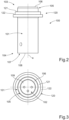
- Figure 2 shows a schematic side view of the tool in Figure 1 .
- the tool comprises a cylindrical wall 101 connecting the open first end 103 and the closed second end 104.
- the first end 103 comprises the front annular portion 105 with its annular end surface 106 at right angles to the central axis X.
- the annular portion 105 at the front end of the tool is arranged to be placed in contact with a corresponding surface on a component to be mounted.
- the first end 103 of the tool comprises the stepped cross-section 120 where each step comprises an annular surface 121, 122 at right angles to the central axis X and where the steps increase in diameter in the direction away from the first end 103.
- the annular surface 121 of a first step is located a predetermined distance behind the annular end surface 106, which distance is substantially equal to the thickness, or height of the component to be mounted.
- the annular surface 122 of a second step is located a predetermined distance behind the annular surface 121 of a first step, which distance is equal to the required axial displacement of the component to be mounted when it is forced into its seat.
- the second end 104 comprises a circular wall 107 with its outer end surface 108 at right angles to the central axis X, which end surface 108 is arranged to be subjected to an external force in order to mount or remove the component.
- Figure 3 shows a schematic plan view of the front end of the tool in Figure 2.
- Figure 3 shows the annular end surface 106 of the annular portion 105 used for centering the component on the tool and around which the component is located for mounting.
- the figure further shows the stepped cross-section 120 and its first and second steps comprising a respective annular surface 121, 122.
- Figure 3 further shows the inner cylindrical cavity 102 and its end wall 109 within the cylindrical wall 101.
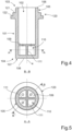
- Figure 4 shows a schematic vertical cross-section of the tool in Figure 2 .
- the tool comprises a cylindrical wall 101 connecting the open first end 103 and the closed second end 104.
- the first end 103 comprises the front annular portion 105 with its annular end surface 106 at right angles to the central axis X.
- the annular portion 105 at the front end of the tool is arranged to be placed in contact with a corresponding surface on a component to be mounted.
- the first end 103 of the tool comprises the stepped cross-section 120 where each step comprises an annular surface 121, 122 at right angles to the central axis X and where the steps increase in diameter in the direction away from the first end 103.
- the annular surface 121 of a first step is located a predetermined distance behind the annular end surface 106, which distance is substantially equal to the thickness, or height of the component to be mounted.
- the annular surface 122 of a second step is located a predetermined distance behind the annular surface 121 of a first step, which distance is equal to the required axial displacement of the component to be mounted when it is forced into its seat.
- the second end 104 comprises a circular wall 107 with its outer end surface 108 at right angles to the central axis X, which end surface 108 is arranged to be subjected to an external force in order to mount or remove the component.
- Figure 4 illustrates a cross-section of the reinforcing lattice structure at the second end 104 of the tool.
- the lattice structure comprises multiple closed cells 110 joined to the cylindrical wall 101 and the circular wall 107 at the rear end of the tool.
- the cells 110 extend between the circular wall 107 at the rear end of the tool and the circular wall 109 of the cavity 102.
- the lattice structure comprises a number of substantially vertical walls 111 extending between and joined to the cylindrical wall 101.
- the walls 111 further extend between and are joined to the circular wall 107 and the end wall 109 of the cylindrical cavity 102 to form a layer of closed cells.
- Figure 5 shows a schematic cross-section of the tool in Figure 4 .
- the cross-section is taken through the reinforced second end 104 at right angles to the central axis X.
- Figure 5 shows the lattice structure comprising multiple closed cells 110 joining the circular wall 107 and the end wall 109 of the cylindrical cavity 102 within the cylindrical wall 101.
- the figure also shows a section through the substantially vertical walls 111 making up the lattice structure.
- Figure 6 shows a schematic vertical cross-section of a first alternative embodiment of the tool in Figure 2 .
- the tool comprises a cylindrical wall 101 connecting the open first end 103 and the closed second end 104.
- the first end 103 comprises the front annular portion 105 with its annular end surface 106 at right angles to the central axis X.
- the annular portion 105 at the front end of the tool is arranged to be placed in contact with a corresponding surface on a component to be mounted.
- the first end 103 of the tool comprises the stepped cross-section 120 where each step comprises an annular surface 121, 122 at right angles to the central axis X and where the steps increase in diameter in the direction away from the first end 103.
- the annular surface 121 of a first step is located a predetermined distance behind the annular end surface 106, which distance is substantially equal to the thickness, or height of the component to be mounted.
- the annular surface 122 of a second step is located a predetermined distance behind the annular surface 121 of a first step, which distance is equal to the required axial displacement of the component to be mounted when it is forced into its seat.
- the second end 104 comprises a circular wall 107 with its outer end surface 108 at right angles to the central axis X, which end surface 108 is arranged to be subjected to an external force in order to mount or remove the component.
- Figure 6 illustrates a cross-section of an alternative reinforcing lattice structure at the second end 104 of the tool.
- the lattice structure comprises layers of multiple closed cells 110a, 110b joined to the cylindrical wall 101 and the circular wall 107 at the rear end of the tool.
- a first layer of cells 110b extends between the circular wall 107 at the rear end of the tool and an intermediate circular wall 112.
- a second layer of cells 110a extends between the intermediate circular wall 112 and the circular wall 109 of the cavity 102.
- the lattice structure comprises a number of substantially vertical walls 113, 114 extending between and joined to the cylindrical wall 101.
- the walls 111 further extend between and are joined to the circular wall 107, the intermediate wall 112 and the end wall 109 of the cylindrical cavity 102 to form two layers of closed cells.
- Figure 7 shows a schematic vertical cross-section of a second alternative embodiment of the tool in Figure 2 .
- the tool comprises a cylindrical wall 101 connecting the open first end 103 and the closed second end 104.
- the first end 103 comprises the front annular portion 105 with its annular end surface 106 at right angles to the central axis X.
- the annular portion 105 at the front end of the tool is arranged to be placed in contact with a corresponding surface on a component to be mounted.
- the first end 103 of the tool comprises the stepped cross-section 120 where each step comprises an annular surface 121, 122 at right angles to the central axis X and where the steps increase in diameter in the direction away from the first end 103.
- the annular surface 121 of a first step is located a predetermined distance behind the annular end surface 106, which distance is substantially equal to the thickness, or height of the component to be mounted.
- the annular surface 122 of a second step is located a predetermined distance behind the annular surface 121 of a first step, which distance is equal to the required axial displacement of the component to be mounted when it is forced into its seat.
- the second end 104 comprises a circular wall 107 with its outer end surface 108 at right angles to the central axis X, which end surface 108 is arranged to be subjected to an external force in order to mount or remove the component.
- Figure 7 illustrates a cross-section of an alternative reinforcing lattice structure at the second end 104 of the tool.
- the lattice structure comprises multiple open cells 115 joined to the cylindrical wall 101 and the circular wall 107 at the rear end of the tool.
- the cells 110 extend between the circular wall 107 and a predetermined distance into the cavity 102.
- the lattice structure comprises a number of substantially vertical walls 116 extending between and joined to the cylindrical wall 101.
- the walls 116 are joined to the circular wall 107 and extend forwards a predetermined distance into the cylindrical cavity 102 to form a grid of open cells 115.
- Figure 8 shows a schematic cross-section of the tool in Figure 7 .
- the cross-section is taken through the reinforced second end 104 at right angles to the central axis X.
- Figure 8 shows the lattice structure comprising multiple open cells 115 joining the circular wall 107 and the second end of the tool within the cylindrical wall 101.
- the figure also shows a section through the substantially vertical walls 116 making up the open cells 115 of the reinforcing lattice structure.
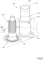
- Figure 9 shows a schematic view of a gearbox and a tool prior to removal of a component.
- the first end of the tool has an annular portion (see Fig.1 ; "105") with an annular end surface at the front of the tool.
- the first end of the tool further comprises a stepped cross-section (see Fig.1 ; "120") where each step comprises an annular surface at right angles to the central axis and where the steps increase in diameter in the direction away from the first end.
- the component When mounting an annular component, such as a bearing or sealing, the component is placed around an outer end portion of the tool and in contact with a corresponding surface formed by the annular surface (see Fig.1 ; "121") of a first step located remote from the outermost end section of the tool.
- the tool can then be positioned concentrically with a corresponding seat in a vehicle gearbox, where after a percussive force is applied to the closed end of the tool.
- the component will then be forced into position in its seat.
- a further second step is located to the rear of the first step supporting the component, which second step has an annular surface (see Fig.1 ; "122”) forming a stop.
- the tool shown in Figure 9 can be identical to any one of the tools in shown in Figures 1-8 , or a similar tool dimensioned for a smaller or larger component.
- Figure 9 shows a tool 200 as described in connection with Figure 1 combined with an extension 203 mounted onto the annular portion (see Fig.1 ; "105") of the tool and in contact with the annular surface (see Fig.1 ; "121") on a first step of a stepped section 204 of the tool.
- the extension 203 will extend forward of the tool 201 and contact the component. As a consequence, the tool will only be in indirect contact with the component to be removed.
- the cylindrical extension 203 mounted on the tool 201 is positioned concentrically onto an annular surface 232 of a component 231 to be removed.
- the component 231 to be removed supports a rotary shaft 230 extending out of the gearbox and through the component 231.
- the combined internal length of the extension 203 and the internal cavity of the tool 201 must be sufficient to accommodate at least the outer end of the shaft 230.
- a circular surface 208 at a rear second end 207 of the tool is subjected to a percussive force in order to force the component 231 through and out of its seat.
- the extension 203 has a cross-section with the same dimensions as the annular surface as the corresponding surface on the tool and on the component to be removed.
- the length of the extension is selected for each individual component to be removed. A relatively short extension can be selected if the component alone needs to be removed out of its seat. However, if the component to be removed supports a rotary shaft extending out through the component, as shown in Figure 9 , then the combined internal length of the extension and the internal cavity of the tool must be able to accommodate the outer end of the shaft.
- Figure 10 shows a schematic flow chart for a manufacturing method for a tool as described in the above examples.
- the manufacturing method involves the following steps.
- the method initially involves starting 300 the manufacturing process.
- a first step 301 the method involves receiving a computer representation of the tool and a plan for the tool to be deposited using an additive manufacturing process.
- the tool comprises an accumulation of layers of material to be deposited by the additive manufacturing process.
- the plan comprises a tool-path representation of the printable product part and process parameters.
- the method involves depositing a layer of powdered polymer material in accordance with the plan.
- the method involves heating the surface of the layer to be covered by the subsequent layer, causing melting/sintering of the layer to be covered.
- a fourth step 304 the method involves checking if the plan has been completed. If this is not the case, then the method returns to the second step 302 and repeats the deposition and heating steps. If it is determined that the plan has been completed, then the method proceeds to a final step 305 and ends the process.
- the additive manufacturing process employed by the method can include fabricating the tool by Laser Powder Bed Fusion (LPBF).
- LPBF Laser Powder Bed Fusion
- MTF Multi Jet Fusion
- the additive manufacturing process includes fabricating the tool from polyetheretherketone (PEEK), polyether-ketoneketone (PEKK), polyamide 11 (PA11) or polyamide 12 (PA12). According to the invention other suitable materials having the required impact resistant properties can be employed.
Landscapes
- Engineering & Computer Science (AREA)
- Mechanical Engineering (AREA)
- Chemical & Material Sciences (AREA)
- Materials Engineering (AREA)
- Manufacturing & Machinery (AREA)
- Physics & Mathematics (AREA)
- Optics & Photonics (AREA)
- General Engineering & Computer Science (AREA)
Abstract
Description
- The invention relates to a heavy-duty vehicle maintenance tool applicable to mount or remove a component from a gearbox and a method for manufacturing such a tool.
- Tools used for maintenance of heavy-duty vehicles, in particular for maintenance of gearboxes in such vehicles are subject to relatively high forces. An example of a maintenance tool used for this purpose is a drift, which is used for mounting or removing components such as bearings and/or sealings used for supporting rotary shafts and other components in a vehicle gearbox.
- A drift for a heavy-duty vehicle gearbox is made from steel and can weigh around 1,5-2 kg depending on the size and diameter of the component to be mounted or removed. The original tool is manufactured by assembling a machined cylindrical section and a flat end section and welding the two metal parts together. Handling a tool this size is very heavy for the person performing the maintenance/repair, in particular if the component to be maintained is located in a confined space or is otherwise difficult to access.
- A further problem is that the tool must be used with care during the maintenance process, as both mounting and removing a component involves the application of a percussive force to one end of the drift. The percussive force can be applied using e.g. a hammer or a similar suitable tool, in order to ease a replacement component into place or to gradually knock a damaged component out of its seat in the gearbox. If the tool is handled or positioned incorrectly, the seat or the area surrounding the component may be damaged during the application of a percussive force.
- The object of the invention is to provide an improved heavy-duty vehicle maintenance tool and a method for manufacturing a tool that solves the above problems.
- The above problems have been solved by a heavy-duty vehicle maintenance tool and a manufacturing method as claimed in the appended claims.
- In this context, the term "heavy-duty vehicle" denotes vehicles such as trucks, wheel loaders and similar work vehicles or commercial vehicles. The tool described below is intended for use in gearbox maintenance for such heavy-duty vehicle. In the subsequent text, the tool is described as having a "front end" and a "rear end". In operation, the front end is located facing the gearbox and contacting the component to be mounted or removed. Similarly, the rear end is located facing an operator of the tool and arranged to be subjected to a percussive force by the operator to either mount or remove the component. For each of these operations, a different tool is used, as the front end of each tool will extend a predetermined distance into a seat or similar opening in the gearbox. The term "closed cells" is used to describe a structure cells with adjoining walls and where each cell comprises multiple walls enclosing an internal space. The invention is not limited to cells of a certain size or wall thickness. The dimensions of the cells can be calculated to provide the rear end of the tool with sufficient strength and impact resistance to withstand repeated blows from a hammer or a percussive tool. A cell having a minor hole or opening in one of its walls is defined as a closed cell and the term is not limited hermetically sealed cells. This is opposed to an "open cell", wherein at least one wall making up the cell has been removed. In operation, the tool will be subjected to a percussive force in order to force a component into or out of its seat. Percussive force can be applied manually, using a hammer, or by means of a separate tool that can generate a percussive force. The term "component" is used to denote a part of the gearbox to be mounted or replaced. In the examples listed here, the component is a bearing or sealing for a rotary or axially slidable component in the gearbox. Such components are mounted in an opening commonly referred to as a seat.
- According to a first aspect, the invention relates to a heavy-duty vehicle maintenance tool applicable to mount or remove a component from a gearbox. The tool has a generally cylindrical shape with a predetermined extension along a central axis. The tool further comprises a cylindrical wall enclosing an inner cylindrical cavity, which cylindrical wall connects an open first end and a closed second end. The first end comprises an annular portion with an annular end surface at right angles to the central axis which annular portion is arranged to be placed in contact with a corresponding surface on a component to be mounted. The operation of the tool will be described in further detail below. The component is a bearing or a sealing for rotary shafts in the gearbox. The second end comprises a circular wall with an outer end surface at right angles to the central axis, which end surface is arranged to be subjected to an external force in order to remove or mount the component. The second end comprises an internal reinforcing lattice structure within the cavity. The tool is a one-piece thermoplastic component.
- According to a first example, the lattice comprises multiple closed cells joined to the circular and cylindrical walls of the cavity and extending a predetermined distance away from the circular wall.
- According to a second example, the lattice comprises multiple layers of closed cells joined to the circular and cylindrical walls of the cavity and extending a predetermined distance away from the circular wall.
- According to a third example, the lattice comprises multiple reinforcing ribs joined to the circular and cylindrical walls of the cavity and extending a predetermined distance away from the circular wall.
- The first end of the tool has a stepped cross-section where each step comprises an annular surface at right angles to the central axis and where the steps increase in diameter in the direction away from the first end. When mounting an annular component, such as a bearing or sealing, the component is placed around an outer end portion of the tool and in contact with a corresponding surface formed by the annular surface of a step located remote from the outermost end section of the tool. The tool can then be positioned concentrically with a corresponding seat in a vehicle gearbox, where after a percussive force is applied to the closed end of the tool. The component will then be forced into position in its seat. A further step located to the rear of the step supporting the component can form a stop. When the rear step contacts the gearbox, this indicates that the component is located correctly, and the tool can be withdrawn. Removal of a component is performed in reverse. In this case, a tool having a first end with a step having an annular surface corresponding to the annular surface of the component is fitted with a cylindrical extension and positioned concentrically over the component. While maintaining the tool and the extension in contact with the component, the second end of the tool is subjected to a percussive force in order to force the component through and out of its seat. The extension has a cross-section with the same annular surface as the corresponding surface on the tool and on the component to be removed. The length of the extension is selected for each individual component to be removed. A relatively short extension can be selected if the component alone needs to be removed out of its seat. However, if the component to be removed supports a rotary shaft extending out through the component, then the combined internal length of the extension and the internal cavity of the tool must be able to accommodate the outer end of the shaft.
- According to a first example, the tool is an additive manufactured component. A tool manufactured in this way can comprise a lattice comprising one or more layers of multiple closed cells joined to the circular and cylindrical walls of the cavity.
- According to a second example, the tool is an injection molded component. A tool manufactured in this way can comprise a lattice comprising multiple reinforcing ribs joined to the circular and cylindrical walls of the cavity and extending a predetermined distance away from the circular wall in the direction of the central axis.
- The tool can be made from a suitable thermoplastic material, such as polyamide 11 (PA11). polyamide 12 (PA12), polyether-etherketone (PEEK) or polyetherketoneketone (PEKK). According to the invention other suitable materials having the required impact resistant properties can be employed.
- According to a second aspect, the invention relates to a method for manufacturing a heavy-duty vehicle maintenance tool as described above. The method involves receiving a computer representation of the tool and a plan for the tool to be deposited using an additive manufacturing process. In this representation, the tool comprises an accumulation of layers of material deposited by the additive manufacturing process. The plan comprises a tool-path representation of the printable product part and process parameters.
- The method further involves the steps of:
- depositing a layer of powdered polymer material in accordance with the plan;
- heating the surface of the layer to be covered by the subsequent layer, causing melting/sintering of the layer to be covered; and
- repeating the deposition and heating steps until the plan is completed.
- According to a first example, the additive manufacturing process includes fabricating the tool by Laser Powder Bed Fusion (LPBF). According to a second example, the additive manufacturing process includes fabricating the tool by Multi Jet Fusion (MJF). The additive manufacturing process includes fabricating the tool from a polymer material such as polyetheretherketone (PEEK), polyether-ketoneketone (PEKK), polyamide 11 (PA11) or polyamide 12 (PA12).
- An advantage of the inventive tool is that it will give a considerable weight saving. Depending on the material selected, a weight saving of up to 85% is possible. In this way, a conventional metal tool weighing 2 kg can be replaced by a thermoplastic tool weighing 300 g. The inventive tool is therefore more ergonomic as it reduces the strain on the operator using the tool.
- A further advantage is that the tool is less likely to damage the component or the gearbox if operated incorrectly. As the thermoplastic material of the tool has a lower hardness than the metallic material of the component or gearbox, the tool itself is unlikely to cause any damage.
- Finally, if the tool is damaged then it will be considerably cheaper to print a new tool using additive manufacturing than to manufacture and weld together the parts required for a tool made from a metallic material.
- In the following text, the invention will be described in detail with reference to the attached drawings. These schematic drawings are used for illustration only and do not in any way limit the scope of the invention. In the drawings:
- Figure 1
- shows a schematic perspective view of a tool according to the invention;
- Figure 2
- shows a schematic side view of the tool in
Figure 1 ; - Figure 3
- shows a schematic plan view of the front end of the tool in
Figure 2 ; - Figure 4
- shows a schematic vertical cross-section of the tool in
Figure 2 ; - Figure 5
- shows a schematic cross-section of the tool in
Figure 4 ; - Figure 6
- shows a schematic vertical cross-section of a first alternative embodiment of the tool in
Figure 4 ; - Figure 7
- shows a schematic vertical cross-section of a second alternative embodiment of the tool in
Figure 4 ; - Figure 8
- shows a schematic cross-section of the tool in
Figure 7 ; - Figure 9
- shows a schematic view of a gearbox and a tool prior to removal of a component; and
- Figure 10
- shows a schematic flow chart for a manufacturing method for a tool.
-
Figure 1 shows a schematic perspective view of a tool according to the invention. The figure shows a heavy-dutyvehicle maintenance tool 100 applicable to mount or remove a component from a gearbox. The tool has a cylindrical shape with a predetermined extension along a central axis X and comprises acylindrical wall 101 enclosing an innercylindrical cavity 102. - The
cylindrical wall 101 connects an openfirst end 103 and a closedsecond end 104. Thefirst end 103 comprises anannular portion 105 with anannular end surface 106 at right angles to the central axis X. Theannular portion 105 is located at the front end of the tool and is arranged to be placed in contact with a corresponding surface on a component to be mounted. Thefirst end 103 of the tool has a steppedcross-section 120 where each step comprises anannular surface first end 103. Theannular surface 121 of a first step is located a predetermined distance behind theannular end surface 106, which distance is substantially equal to the thickness, or height of the component to be mounted. Theannular surface 122 of a second step is located a predetermined distance behind theannular surface 121 of a first step, which distance is equal to the required axial displacement of the component to be mounted when it is forced into its seat. Thesecond end 104 comprises acircular wall 107 with anouter end surface 108 at right angles to the central axis X, whichend surface 108 is arranged to be subjected to an external force in order to mount or remove the component. Thesecond end 104 comprises an internal reinforcing lattice structure within thecavity 102. The tool is a one-piece thermoplastic component made by additive manufacturing. The internal lattice structure will be described in further detail below. Note that the reference numbering used forFigure 1 will be retained for the same component parts in the subsequent examples described inFigures 2-8 . - In operation, a component to be mounted is placed around the
annular portion 105 at thefirst end 103 of the tool. The component is further located by pushing it into contact with a corresponding surface formed by theannular surface 121 of a first step located behind theannular end surface 106 of the tool. The tool can then be positioned concentrically with a corresponding seat in a vehicle gearbox (seeFig.9 ), where after a percussive force is applied to the closed end of the tool. The component will then be forced into position in its seat. Theannular surface 122 of a second step, located to the rear of the first step supporting the component, can form a stop. When the second step contacts a surface of the gearbox surrounding the seat, this indicates that the component is located correctly, and the tool can be withdrawn. The component mounted in this way can be a bearing or sealing. -
Figure 2 shows a schematic side view of the tool inFigure 1 . As shown inFigure 2 , the tool comprises acylindrical wall 101 connecting the openfirst end 103 and the closedsecond end 104. Thefirst end 103 comprises the frontannular portion 105 with itsannular end surface 106 at right angles to the central axis X. Theannular portion 105 at the front end of the tool is arranged to be placed in contact with a corresponding surface on a component to be mounted. Thefirst end 103 of the tool comprises the steppedcross-section 120 where each step comprises anannular surface first end 103. Theannular surface 121 of a first step is located a predetermined distance behind theannular end surface 106, which distance is substantially equal to the thickness, or height of the component to be mounted. Theannular surface 122 of a second step is located a predetermined distance behind theannular surface 121 of a first step, which distance is equal to the required axial displacement of the component to be mounted when it is forced into its seat. Thesecond end 104 comprises acircular wall 107 with itsouter end surface 108 at right angles to the central axis X, whichend surface 108 is arranged to be subjected to an external force in order to mount or remove the component. -
Figure 3 shows a schematic plan view of the front end of the tool inFigure 2. Figure 3 shows theannular end surface 106 of theannular portion 105 used for centering the component on the tool and around which the component is located for mounting. The figure further shows the steppedcross-section 120 and its first and second steps comprising a respectiveannular surface Figure 3 further shows the innercylindrical cavity 102 and itsend wall 109 within thecylindrical wall 101. -
Figure 4 shows a schematic vertical cross-section of the tool inFigure 2 . As shown inFigure 4 , the tool comprises acylindrical wall 101 connecting the openfirst end 103 and the closedsecond end 104. Thefirst end 103 comprises the frontannular portion 105 with itsannular end surface 106 at right angles to the central axis X. Theannular portion 105 at the front end of the tool is arranged to be placed in contact with a corresponding surface on a component to be mounted. Thefirst end 103 of the tool comprises the steppedcross-section 120 where each step comprises anannular surface first end 103. Theannular surface 121 of a first step is located a predetermined distance behind theannular end surface 106, which distance is substantially equal to the thickness, or height of the component to be mounted. Theannular surface 122 of a second step is located a predetermined distance behind theannular surface 121 of a first step, which distance is equal to the required axial displacement of the component to be mounted when it is forced into its seat. Thesecond end 104 comprises acircular wall 107 with itsouter end surface 108 at right angles to the central axis X, whichend surface 108 is arranged to be subjected to an external force in order to mount or remove the component. -
Figure 4 illustrates a cross-section of the reinforcing lattice structure at thesecond end 104 of the tool. In this example the lattice structure comprises multipleclosed cells 110 joined to thecylindrical wall 101 and thecircular wall 107 at the rear end of the tool. Thecells 110 extend between thecircular wall 107 at the rear end of the tool and thecircular wall 109 of thecavity 102. The lattice structure comprises a number of substantiallyvertical walls 111 extending between and joined to thecylindrical wall 101. Thewalls 111 further extend between and are joined to thecircular wall 107 and theend wall 109 of thecylindrical cavity 102 to form a layer of closed cells. -
Figure 5 shows a schematic cross-section of the tool inFigure 4 . In particular, the cross-section is taken through the reinforcedsecond end 104 at right angles to the central axis X.Figure 5 shows the lattice structure comprising multipleclosed cells 110 joining thecircular wall 107 and theend wall 109 of thecylindrical cavity 102 within thecylindrical wall 101. The figure also shows a section through the substantiallyvertical walls 111 making up the lattice structure. -
Figure 6 shows a schematic vertical cross-section of a first alternative embodiment of the tool inFigure 2 . As shown inFigure 6 , the tool comprises acylindrical wall 101 connecting the openfirst end 103 and the closedsecond end 104. Thefirst end 103 comprises the frontannular portion 105 with itsannular end surface 106 at right angles to the central axis X. Theannular portion 105 at the front end of the tool is arranged to be placed in contact with a corresponding surface on a component to be mounted. Thefirst end 103 of the tool comprises the steppedcross-section 120 where each step comprises anannular surface first end 103. Theannular surface 121 of a first step is located a predetermined distance behind theannular end surface 106, which distance is substantially equal to the thickness, or height of the component to be mounted. Theannular surface 122 of a second step is located a predetermined distance behind theannular surface 121 of a first step, which distance is equal to the required axial displacement of the component to be mounted when it is forced into its seat. Thesecond end 104 comprises acircular wall 107 with itsouter end surface 108 at right angles to the central axis X, whichend surface 108 is arranged to be subjected to an external force in order to mount or remove the component. -
Figure 6 illustrates a cross-section of an alternative reinforcing lattice structure at thesecond end 104 of the tool. In this example the lattice structure comprises layers of multipleclosed cells cylindrical wall 101 and thecircular wall 107 at the rear end of the tool. A first layer ofcells 110b extends between thecircular wall 107 at the rear end of the tool and an intermediatecircular wall 112. A second layer ofcells 110a extends between the intermediatecircular wall 112 and thecircular wall 109 of thecavity 102. The lattice structure comprises a number of substantiallyvertical walls cylindrical wall 101. Thewalls 111 further extend between and are joined to thecircular wall 107, theintermediate wall 112 and theend wall 109 of thecylindrical cavity 102 to form two layers of closed cells. -
Figure 7 shows a schematic vertical cross-section of a second alternative embodiment of the tool inFigure 2 . As shown inFigure 7 , the tool comprises acylindrical wall 101 connecting the openfirst end 103 and the closedsecond end 104. Thefirst end 103 comprises the frontannular portion 105 with itsannular end surface 106 at right angles to the central axis X. Theannular portion 105 at the front end of the tool is arranged to be placed in contact with a corresponding surface on a component to be mounted. Thefirst end 103 of the tool comprises the steppedcross-section 120 where each step comprises anannular surface first end 103. Theannular surface 121 of a first step is located a predetermined distance behind theannular end surface 106, which distance is substantially equal to the thickness, or height of the component to be mounted. Theannular surface 122 of a second step is located a predetermined distance behind theannular surface 121 of a first step, which distance is equal to the required axial displacement of the component to be mounted when it is forced into its seat. Thesecond end 104 comprises acircular wall 107 with itsouter end surface 108 at right angles to the central axis X, whichend surface 108 is arranged to be subjected to an external force in order to mount or remove the component. -
Figure 7 illustrates a cross-section of an alternative reinforcing lattice structure at thesecond end 104 of the tool. In this example the lattice structure comprises multipleopen cells 115 joined to thecylindrical wall 101 and thecircular wall 107 at the rear end of the tool. Thecells 110 extend between thecircular wall 107 and a predetermined distance into thecavity 102. The lattice structure comprises a number of substantiallyvertical walls 116 extending between and joined to thecylindrical wall 101. Thewalls 116 are joined to thecircular wall 107 and extend forwards a predetermined distance into thecylindrical cavity 102 to form a grid ofopen cells 115. -
Figure 8 shows a schematic cross-section of the tool inFigure 7 . In particular, the cross-section is taken through the reinforcedsecond end 104 at right angles to the central axis X.Figure 8 shows the lattice structure comprising multipleopen cells 115 joining thecircular wall 107 and the second end of the tool within thecylindrical wall 101. The figure also shows a section through the substantiallyvertical walls 116 making up theopen cells 115 of the reinforcing lattice structure. -
Figure 9 shows a schematic view of a gearbox and a tool prior to removal of a component. As described in connection withFigure 1 above, the first end of the tool has an annular portion (seeFig.1 ; "105") with an annular end surface at the front of the tool. With reference toFigure 1 , the first end of the tool further comprises a stepped cross-section (seeFig.1 ; "120") where each step comprises an annular surface at right angles to the central axis and where the steps increase in diameter in the direction away from the first end. When mounting an annular component, such as a bearing or sealing, the component is placed around an outer end portion of the tool and in contact with a corresponding surface formed by the annular surface (seeFig.1 ; "121") of a first step located remote from the outermost end section of the tool. The tool can then be positioned concentrically with a corresponding seat in a vehicle gearbox, where after a percussive force is applied to the closed end of the tool. The component will then be forced into position in its seat. A further second step is located to the rear of the first step supporting the component, which second step has an annular surface (seeFig.1 ; "122") forming a stop. The tool shown inFigure 9 can be identical to any one of the tools in shown inFigures 1-8 , or a similar tool dimensioned for a smaller or larger component. - Prior to removing a component, the tool shown in
Figure 1 is used in combination with an extension device.Figure 9 shows atool 200 as described in connection withFigure 1 combined with anextension 203 mounted onto the annular portion (seeFig.1 ; "105") of the tool and in contact with the annular surface (seeFig.1 ; "121") on a first step of a steppedsection 204 of the tool. Theextension 203 will extend forward of thetool 201 and contact the component. As a consequence, the tool will only be in indirect contact with the component to be removed. - In operation, the
cylindrical extension 203 mounted on thetool 201 is positioned concentrically onto anannular surface 232 of acomponent 231 to be removed. As can be seen inFigure 9 , thecomponent 231 to be removed supports arotary shaft 230 extending out of the gearbox and through thecomponent 231. The combined internal length of theextension 203 and the internal cavity of thetool 201 must be sufficient to accommodate at least the outer end of theshaft 230. While maintaining thetool 201 and theextension 203 in contact with thecomponent 231, acircular surface 208 at a rearsecond end 207 of the tool is subjected to a percussive force in order to force thecomponent 231 through and out of its seat. Theextension 203 has a cross-section with the same dimensions as the annular surface as the corresponding surface on the tool and on the component to be removed. The length of the extension is selected for each individual component to be removed. A relatively short extension can be selected if the component alone needs to be removed out of its seat. However, if the component to be removed supports a rotary shaft extending out through the component, as shown inFigure 9 , then the combined internal length of the extension and the internal cavity of the tool must be able to accommodate the outer end of the shaft. -
Figure 10 shows a schematic flow chart for a manufacturing method for a tool as described in the above examples. The manufacturing method involves the following steps. The method initially involves starting 300 the manufacturing process. In afirst step 301 the method involves receiving a computer representation of the tool and a plan for the tool to be deposited using an additive manufacturing process. In this form the tool comprises an accumulation of layers of material to be deposited by the additive manufacturing process. The plan comprises a tool-path representation of the printable product part and process parameters. In asecond step 302 the method involves depositing a layer of powdered polymer material in accordance with the plan. In athird step 303 the method involves heating the surface of the layer to be covered by the subsequent layer, causing melting/sintering of the layer to be covered. In afourth step 304 the method involves checking if the plan has been completed. If this is not the case, then the method returns to thesecond step 302 and repeats the deposition and heating steps. If it is determined that the plan has been completed, then the method proceeds to afinal step 305 and ends the process. - The additive manufacturing process employed by the method can include fabricating the tool by Laser Powder Bed Fusion (LPBF). Alternatively, the additive manufacturing process can include fabricating the tool by Multi Jet Fusion (MJF).
- The additive manufacturing process includes fabricating the tool from polyetheretherketone (PEEK), polyether-ketoneketone (PEKK), polyamide 11 (PA11) or polyamide 12 (PA12). According to the invention other suitable materials having the required impact resistant properties can be employed.
- The invention should not be deemed to be limited to the embodiments described above, but rather a number of further variants and modifications are conceivable within the scope of the following patent claims.
Claims (14)
- Heavy-duty vehicle maintenance tool (100) applicable to mount or remove a component from a gearbox, which tool has a cylindrical shape with a predetermined extension along a central axis (X); the tool further comprising a cylindrical wall (101) enclosing an inner cylindrical cavity (102) and connecting an open first end (103) and a closed second end (104), wherein- the first end (103) comprises an annular portion (105) with an annular end surface (106) at right angles to the central axis (X) which annular portion (105) is arranged to be placed in contact with a corresponding surface on a component to be mounted;- the second end (104) comprises a circular wall (107) with an outer end surface (108) at right angles to the central axis (X), which end surface (108) is arranged to be subjected to an external force in order to mount or remove the component;- the second end (104) comprises an internal reinforcing lattice structure (110) within the cavity (102); and wherein the tool is a one-piece thermoplastic component.
- Tool according to claim 1, wherein the lattice comprises multiple closed cells (110) joined to the circular and cylindrical walls of the cavity and extending a predetermined distance away from the circular wall (107).
- Tool according to claim 2, wherein the lattice comprises multiple layers (110a, 110b) of closed cells.
- Tool according to claim 1, wherein the lattice comprises multiple layers (110a, 110b) of closed cells
- Tool according to any one of claims 1-.4, wherein the first end (103) has a stepped cross-section (120) comprising at least one step and where each step comprises an annular surface (121, 122) at right angles to the central axis (X) and where the steps increase in diameter in the direction away from the first end (103).
- Tool according to any one of claims 1-5, wherein the tool is an additive manufactured component.
- Tool according to any one of claims 1-6, wherein the tool is made from polyamide 11 (PA11) or polyamide 12 (PA12).
- Tool according to any one of claims 1-6, wherein the tool is made from polyether-etherketone (PEEK) or polyetherketoneketone (PEKK).
- Tool according to any one of claims 1-8, wherein the tool is a drift applicable to mount or remove bearings, sealings and other annular components in a gearbox.
- Method for manufacturing a heavy-duty vehicle maintenance tool according to claim 1, the method involving receiving a computer representation of the tool and a plan for the tool to be deposited using an additive manufacturing process; the tool comprising an accumulation of layers of material deposited by the additive manufacturing process; and the plan comprising a tool-path representation of the printable product part and process parameters; wherein the method involves- depositing a layer of powdered polymer material in accordance with the plan;- heating the surface of the layer to be covered by the subsequent layer, causing melting/ sintering of the layer to be covered; and- repeating the deposition and heating steps until the plan is completed.
- The method according to claim 10 wherein the additive manufacturing process includes fabricating the tool by Laser Powder Bed Fusion (LPBF).
- The method according to claim 10 wherein the additive manufacturing process includes fabricating the tool by Multi Jet Fusion (MJF).
- The method according to any one of claims 10-12, wherein the additive manufacturing process includes fabricating the tool from polyetheretherketone (PEEK). or polyether-ketoneketone (PEKK).
- The method according to any one of claims 10-12, wherein the additive manufacturing process includes fabricating the tool from polyamide 11 (PA11) or polyamide 12 (PA12).
Priority Applications (2)
| Application Number | Priority Date | Filing Date | Title |
|---|---|---|---|
| EP21201971.5A EP4163059B1 (en) | 2021-10-11 | 2021-10-11 | A heavy-duty vehicle maintenance tool and a method for manufacturing such a tool |
| US17/951,437 US12343847B2 (en) | 2021-10-11 | 2022-09-23 | Heavy-duty vehicle maintenance tool and a method for manufacturing such a tool |
Applications Claiming Priority (1)
| Application Number | Priority Date | Filing Date | Title |
|---|---|---|---|
| EP21201971.5A EP4163059B1 (en) | 2021-10-11 | 2021-10-11 | A heavy-duty vehicle maintenance tool and a method for manufacturing such a tool |
Publications (2)
| Publication Number | Publication Date |
|---|---|
| EP4163059A1 true EP4163059A1 (en) | 2023-04-12 |
| EP4163059B1 EP4163059B1 (en) | 2024-06-26 |
Family
ID=78463364
Family Applications (1)
| Application Number | Title | Priority Date | Filing Date |
|---|---|---|---|
| EP21201971.5A Active EP4163059B1 (en) | 2021-10-11 | 2021-10-11 | A heavy-duty vehicle maintenance tool and a method for manufacturing such a tool |
Country Status (2)
| Country | Link |
|---|---|
| US (1) | US12343847B2 (en) |
| EP (1) | EP4163059B1 (en) |
Citations (3)
| Publication number | Priority date | Publication date | Assignee | Title |
|---|---|---|---|---|
| US4586228A (en) * | 1984-08-16 | 1986-05-06 | Rodolf Charles A | Tool kit for installing transmission seals |
| US5528809A (en) * | 1994-01-14 | 1996-06-25 | Green; Jace N. | Dual-sided bushing installation tool for vehicle transmissions |
| US7191504B1 (en) * | 2005-03-24 | 2007-03-20 | Sonnax Industries, Inc. | Universal bushing tool and method of use |
Family Cites Families (4)
| Publication number | Priority date | Publication date | Assignee | Title |
|---|---|---|---|---|
| CN103143731A (en) | 2012-12-28 | 2013-06-12 | 大连宏润复合轴承有限公司 | Machine tool main shaft bearing |
| US20160238324A1 (en) * | 2013-09-23 | 2016-08-18 | United Technologies Corporation | Method of generating support structure of tube components to become functional features |
| US20190160638A1 (en) * | 2017-11-30 | 2019-05-30 | Saint-Gobain Performance Plastics Corporation | Tool assembly for seals and methods of using the same |
| EP3871859A1 (en) | 2020-02-26 | 2021-09-01 | Hewlett-Packard Development Company, L.P. | Three-dimensional printing |
-
2021
- 2021-10-11 EP EP21201971.5A patent/EP4163059B1/en active Active
-
2022
- 2022-09-23 US US17/951,437 patent/US12343847B2/en active Active
Patent Citations (3)
| Publication number | Priority date | Publication date | Assignee | Title |
|---|---|---|---|---|
| US4586228A (en) * | 1984-08-16 | 1986-05-06 | Rodolf Charles A | Tool kit for installing transmission seals |
| US5528809A (en) * | 1994-01-14 | 1996-06-25 | Green; Jace N. | Dual-sided bushing installation tool for vehicle transmissions |
| US7191504B1 (en) * | 2005-03-24 | 2007-03-20 | Sonnax Industries, Inc. | Universal bushing tool and method of use |
Also Published As
| Publication number | Publication date |
|---|---|
| EP4163059B1 (en) | 2024-06-26 |
| US20230114309A1 (en) | 2023-04-13 |
| US12343847B2 (en) | 2025-07-01 |
Similar Documents
| Publication | Publication Date | Title |
|---|---|---|
| EP1872893B1 (en) | Rotary tool for friction stirring-spot welding and friction stirring-spot welding method using the rotary tool | |
| EP2538119B1 (en) | Welded differential case assembly | |
| US20170022614A1 (en) | Methods for repair of aircraft wheel and brake parts | |
| EP2873620B1 (en) | Repair method for fuselage components of aircraft or spacecraft | |
| US9919379B1 (en) | Friction rivet for joining different materials | |
| EP1563924A1 (en) | Process for producing tubular ring with beads and die for use therein | |
| US9045068B2 (en) | One-piece seat back structure | |
| JP2012196680A (en) | Hole repair method using friction stir spot welding | |
| CN1564724A (en) | Method for joining of structural members by friction plug welding | |
| WO2015017856A1 (en) | Lightweight steering knuckle assembly and method of manufacturing the same | |
| EP4163059B1 (en) | A heavy-duty vehicle maintenance tool and a method for manufacturing such a tool | |
| EP2942540B1 (en) | Piston housing system and apparatus | |
| EP3385097B1 (en) | Stabilizer link for automobile suspensions | |
| CZ20032819A3 (en) | Method for fixing a crosspiece and an arm, particularly for a semi-rigid axle | |
| US20170129040A1 (en) | Method for producing a chassis component | |
| EP3674103B1 (en) | Modular axle shaft assemblies for use with racing vehicles and other vehicles | |
| US8448837B2 (en) | Method for manufacturing a one-piece annular metal part having a reinforcing insert of composite material | |
| US5966812A (en) | Method of repairing vehicle axle housings | |
| EP2156922B1 (en) | Method of manufacturing thin wall isogrid casings | |
| WO2013021999A1 (en) | Processing apparatus and processing method | |
| EP3816482A1 (en) | Internally damped gear | |
| US20170030398A1 (en) | Method of manufacturing light rotor shaft for eco-friendly vehicles | |
| EP4039498A1 (en) | Axle housing assembly having a spindle and method of manufacture | |
| US7530487B2 (en) | Method of welding onto thin components | |
| CN116984593A (en) | In-situ repair method for very large single-piece castings |
Legal Events
| Date | Code | Title | Description |
|---|---|---|---|
| PUAI | Public reference made under article 153(3) epc to a published international application that has entered the european phase |
Free format text: ORIGINAL CODE: 0009012 |
|
| STAA | Information on the status of an ep patent application or granted ep patent |
Free format text: STATUS: THE APPLICATION HAS BEEN PUBLISHED |
|
| AK | Designated contracting states |
Kind code of ref document: A1 Designated state(s): AL AT BE BG CH CY CZ DE DK EE ES FI FR GB GR HR HU IE IS IT LI LT LU LV MC MK MT NL NO PL PT RO RS SE SI SK SM TR |
|
| STAA | Information on the status of an ep patent application or granted ep patent |
Free format text: STATUS: REQUEST FOR EXAMINATION WAS MADE |
|
| 17P | Request for examination filed |
Effective date: 20230811 |
|
| RBV | Designated contracting states (corrected) |
Designated state(s): AL AT BE BG CH CY CZ DE DK EE ES FI FR GB GR HR HU IE IS IT LI LT LU LV MC MK MT NL NO PL PT RO RS SE SI SK SM TR |
|
| GRAP | Despatch of communication of intention to grant a patent |
Free format text: ORIGINAL CODE: EPIDOSNIGR1 |
|
| STAA | Information on the status of an ep patent application or granted ep patent |
Free format text: STATUS: GRANT OF PATENT IS INTENDED |
|
| INTG | Intention to grant announced |
Effective date: 20240117 |
|
| GRAS | Grant fee paid |
Free format text: ORIGINAL CODE: EPIDOSNIGR3 |
|
| GRAA | (expected) grant |
Free format text: ORIGINAL CODE: 0009210 |
|
| STAA | Information on the status of an ep patent application or granted ep patent |
Free format text: STATUS: THE PATENT HAS BEEN GRANTED |
|
| AK | Designated contracting states |
Kind code of ref document: B1 Designated state(s): AL AT BE BG CH CY CZ DE DK EE ES FI FR GB GR HR HU IE IS IT LI LT LU LV MC MK MT NL NO PL PT RO RS SE SI SK SM TR |
|
| REG | Reference to a national code |
Ref country code: GB Ref legal event code: FG4D |
|
| REG | Reference to a national code |
Ref country code: CH Ref legal event code: EP |
|
| REG | Reference to a national code |
Ref country code: DE Ref legal event code: R096 Ref document number: 602021014760 Country of ref document: DE |
|
| PG25 | Lapsed in a contracting state [announced via postgrant information from national office to epo] |
Ref country code: BG Free format text: LAPSE BECAUSE OF FAILURE TO SUBMIT A TRANSLATION OF THE DESCRIPTION OR TO PAY THE FEE WITHIN THE PRESCRIBED TIME-LIMIT Effective date: 20240626 |
|
| PG25 | Lapsed in a contracting state [announced via postgrant information from national office to epo] |
Ref country code: FI Free format text: LAPSE BECAUSE OF FAILURE TO SUBMIT A TRANSLATION OF THE DESCRIPTION OR TO PAY THE FEE WITHIN THE PRESCRIBED TIME-LIMIT Effective date: 20240626 Ref country code: HR Free format text: LAPSE BECAUSE OF FAILURE TO SUBMIT A TRANSLATION OF THE DESCRIPTION OR TO PAY THE FEE WITHIN THE PRESCRIBED TIME-LIMIT Effective date: 20240626 |
|
| REG | Reference to a national code |
Ref country code: LT Ref legal event code: MG9D |
|
| PG25 | Lapsed in a contracting state [announced via postgrant information from national office to epo] |
Ref country code: GR Free format text: LAPSE BECAUSE OF FAILURE TO SUBMIT A TRANSLATION OF THE DESCRIPTION OR TO PAY THE FEE WITHIN THE PRESCRIBED TIME-LIMIT Effective date: 20240927 |
|
| PG25 | Lapsed in a contracting state [announced via postgrant information from national office to epo] |
Ref country code: LV Free format text: LAPSE BECAUSE OF FAILURE TO SUBMIT A TRANSLATION OF THE DESCRIPTION OR TO PAY THE FEE WITHIN THE PRESCRIBED TIME-LIMIT Effective date: 20240626 |
|
| REG | Reference to a national code |
Ref country code: NL Ref legal event code: MP Effective date: 20240626 |
|
| PG25 | Lapsed in a contracting state [announced via postgrant information from national office to epo] |
Ref country code: NO Free format text: LAPSE BECAUSE OF FAILURE TO SUBMIT A TRANSLATION OF THE DESCRIPTION OR TO PAY THE FEE WITHIN THE PRESCRIBED TIME-LIMIT Effective date: 20240926 Ref country code: LV Free format text: LAPSE BECAUSE OF FAILURE TO SUBMIT A TRANSLATION OF THE DESCRIPTION OR TO PAY THE FEE WITHIN THE PRESCRIBED TIME-LIMIT Effective date: 20240626 Ref country code: HR Free format text: LAPSE BECAUSE OF FAILURE TO SUBMIT A TRANSLATION OF THE DESCRIPTION OR TO PAY THE FEE WITHIN THE PRESCRIBED TIME-LIMIT Effective date: 20240626 Ref country code: GR Free format text: LAPSE BECAUSE OF FAILURE TO SUBMIT A TRANSLATION OF THE DESCRIPTION OR TO PAY THE FEE WITHIN THE PRESCRIBED TIME-LIMIT Effective date: 20240927 Ref country code: FI Free format text: LAPSE BECAUSE OF FAILURE TO SUBMIT A TRANSLATION OF THE DESCRIPTION OR TO PAY THE FEE WITHIN THE PRESCRIBED TIME-LIMIT Effective date: 20240626 Ref country code: BG Free format text: LAPSE BECAUSE OF FAILURE TO SUBMIT A TRANSLATION OF THE DESCRIPTION OR TO PAY THE FEE WITHIN THE PRESCRIBED TIME-LIMIT Effective date: 20240626 Ref country code: RS Free format text: LAPSE BECAUSE OF FAILURE TO SUBMIT A TRANSLATION OF THE DESCRIPTION OR TO PAY THE FEE WITHIN THE PRESCRIBED TIME-LIMIT Effective date: 20240926 |
|
| PG25 | Lapsed in a contracting state [announced via postgrant information from national office to epo] |
Ref country code: NL Free format text: LAPSE BECAUSE OF FAILURE TO SUBMIT A TRANSLATION OF THE DESCRIPTION OR TO PAY THE FEE WITHIN THE PRESCRIBED TIME-LIMIT Effective date: 20240626 |
|
| REG | Reference to a national code |
Ref country code: AT Ref legal event code: MK05 Ref document number: 1697324 Country of ref document: AT Kind code of ref document: T Effective date: 20240626 |
|
| PG25 | Lapsed in a contracting state [announced via postgrant information from national office to epo] |
Ref country code: NL Free format text: LAPSE BECAUSE OF FAILURE TO SUBMIT A TRANSLATION OF THE DESCRIPTION OR TO PAY THE FEE WITHIN THE PRESCRIBED TIME-LIMIT Effective date: 20240626 |
|
| PG25 | Lapsed in a contracting state [announced via postgrant information from national office to epo] |
Ref country code: PT Free format text: LAPSE BECAUSE OF FAILURE TO SUBMIT A TRANSLATION OF THE DESCRIPTION OR TO PAY THE FEE WITHIN THE PRESCRIBED TIME-LIMIT Effective date: 20241028 |
|
| PG25 | Lapsed in a contracting state [announced via postgrant information from national office to epo] |
Ref country code: PT Free format text: LAPSE BECAUSE OF FAILURE TO SUBMIT A TRANSLATION OF THE DESCRIPTION OR TO PAY THE FEE WITHIN THE PRESCRIBED TIME-LIMIT Effective date: 20241028 |
|
| PGFP | Annual fee paid to national office [announced via postgrant information from national office to epo] |
Ref country code: DE Payment date: 20241029 Year of fee payment: 4 |
|
| PG25 | Lapsed in a contracting state [announced via postgrant information from national office to epo] |
Ref country code: PL Free format text: LAPSE BECAUSE OF FAILURE TO SUBMIT A TRANSLATION OF THE DESCRIPTION OR TO PAY THE FEE WITHIN THE PRESCRIBED TIME-LIMIT Effective date: 20240626 |
|
| PG25 | Lapsed in a contracting state [announced via postgrant information from national office to epo] |
Ref country code: EE Free format text: LAPSE BECAUSE OF FAILURE TO SUBMIT A TRANSLATION OF THE DESCRIPTION OR TO PAY THE FEE WITHIN THE PRESCRIBED TIME-LIMIT Effective date: 20240626 |
|
| PG25 | Lapsed in a contracting state [announced via postgrant information from national office to epo] |
Ref country code: AT Free format text: LAPSE BECAUSE OF FAILURE TO SUBMIT A TRANSLATION OF THE DESCRIPTION OR TO PAY THE FEE WITHIN THE PRESCRIBED TIME-LIMIT Effective date: 20240626 Ref country code: IS Free format text: LAPSE BECAUSE OF FAILURE TO SUBMIT A TRANSLATION OF THE DESCRIPTION OR TO PAY THE FEE WITHIN THE PRESCRIBED TIME-LIMIT Effective date: 20241026 |
|
| PGFP | Annual fee paid to national office [announced via postgrant information from national office to epo] |
Ref country code: FR Payment date: 20241025 Year of fee payment: 4 |
|
| PG25 | Lapsed in a contracting state [announced via postgrant information from national office to epo] |
Ref country code: CZ Free format text: LAPSE BECAUSE OF FAILURE TO SUBMIT A TRANSLATION OF THE DESCRIPTION OR TO PAY THE FEE WITHIN THE PRESCRIBED TIME-LIMIT Effective date: 20240626 |
|
| PG25 | Lapsed in a contracting state [announced via postgrant information from national office to epo] |
Ref country code: RO Free format text: LAPSE BECAUSE OF FAILURE TO SUBMIT A TRANSLATION OF THE DESCRIPTION OR TO PAY THE FEE WITHIN THE PRESCRIBED TIME-LIMIT Effective date: 20240626 Ref country code: SK Free format text: LAPSE BECAUSE OF FAILURE TO SUBMIT A TRANSLATION OF THE DESCRIPTION OR TO PAY THE FEE WITHIN THE PRESCRIBED TIME-LIMIT Effective date: 20240626 |
|
| PG25 | Lapsed in a contracting state [announced via postgrant information from national office to epo] |
Ref country code: SM Free format text: LAPSE BECAUSE OF FAILURE TO SUBMIT A TRANSLATION OF THE DESCRIPTION OR TO PAY THE FEE WITHIN THE PRESCRIBED TIME-LIMIT Effective date: 20240626 Ref country code: ES Free format text: LAPSE BECAUSE OF FAILURE TO SUBMIT A TRANSLATION OF THE DESCRIPTION OR TO PAY THE FEE WITHIN THE PRESCRIBED TIME-LIMIT Effective date: 20240626 |
|
| PG25 | Lapsed in a contracting state [announced via postgrant information from national office to epo] |
Ref country code: SM Free format text: LAPSE BECAUSE OF FAILURE TO SUBMIT A TRANSLATION OF THE DESCRIPTION OR TO PAY THE FEE WITHIN THE PRESCRIBED TIME-LIMIT Effective date: 20240626 Ref country code: SK Free format text: LAPSE BECAUSE OF FAILURE TO SUBMIT A TRANSLATION OF THE DESCRIPTION OR TO PAY THE FEE WITHIN THE PRESCRIBED TIME-LIMIT Effective date: 20240626 Ref country code: RO Free format text: LAPSE BECAUSE OF FAILURE TO SUBMIT A TRANSLATION OF THE DESCRIPTION OR TO PAY THE FEE WITHIN THE PRESCRIBED TIME-LIMIT Effective date: 20240626 Ref country code: PL Free format text: LAPSE BECAUSE OF FAILURE TO SUBMIT A TRANSLATION OF THE DESCRIPTION OR TO PAY THE FEE WITHIN THE PRESCRIBED TIME-LIMIT Effective date: 20240626 Ref country code: IS Free format text: LAPSE BECAUSE OF FAILURE TO SUBMIT A TRANSLATION OF THE DESCRIPTION OR TO PAY THE FEE WITHIN THE PRESCRIBED TIME-LIMIT Effective date: 20241026 Ref country code: ES Free format text: LAPSE BECAUSE OF FAILURE TO SUBMIT A TRANSLATION OF THE DESCRIPTION OR TO PAY THE FEE WITHIN THE PRESCRIBED TIME-LIMIT Effective date: 20240626 Ref country code: EE Free format text: LAPSE BECAUSE OF FAILURE TO SUBMIT A TRANSLATION OF THE DESCRIPTION OR TO PAY THE FEE WITHIN THE PRESCRIBED TIME-LIMIT Effective date: 20240626 Ref country code: CZ Free format text: LAPSE BECAUSE OF FAILURE TO SUBMIT A TRANSLATION OF THE DESCRIPTION OR TO PAY THE FEE WITHIN THE PRESCRIBED TIME-LIMIT Effective date: 20240626 Ref country code: AT Free format text: LAPSE BECAUSE OF FAILURE TO SUBMIT A TRANSLATION OF THE DESCRIPTION OR TO PAY THE FEE WITHIN THE PRESCRIBED TIME-LIMIT Effective date: 20240626 |
|
| PG25 | Lapsed in a contracting state [announced via postgrant information from national office to epo] |
Ref country code: IT Free format text: LAPSE BECAUSE OF FAILURE TO SUBMIT A TRANSLATION OF THE DESCRIPTION OR TO PAY THE FEE WITHIN THE PRESCRIBED TIME-LIMIT Effective date: 20240626 |
|
| REG | Reference to a national code |
Ref country code: DE Ref legal event code: R097 Ref document number: 602021014760 Country of ref document: DE |
|
| PG25 | Lapsed in a contracting state [announced via postgrant information from national office to epo] |
Ref country code: DK Free format text: LAPSE BECAUSE OF FAILURE TO SUBMIT A TRANSLATION OF THE DESCRIPTION OR TO PAY THE FEE WITHIN THE PRESCRIBED TIME-LIMIT Effective date: 20240626 |
|
| PLBE | No opposition filed within time limit |
Free format text: ORIGINAL CODE: 0009261 |
|
| STAA | Information on the status of an ep patent application or granted ep patent |
Free format text: STATUS: NO OPPOSITION FILED WITHIN TIME LIMIT |
|
| REG | Reference to a national code |
Ref country code: CH Ref legal event code: PL |
|
| 26N | No opposition filed |
Effective date: 20250327 |
|
| PG25 | Lapsed in a contracting state [announced via postgrant information from national office to epo] |
Ref country code: MC Free format text: LAPSE BECAUSE OF FAILURE TO SUBMIT A TRANSLATION OF THE DESCRIPTION OR TO PAY THE FEE WITHIN THE PRESCRIBED TIME-LIMIT Effective date: 20240626 |
|
| PG25 | Lapsed in a contracting state [announced via postgrant information from national office to epo] |
Ref country code: LU Free format text: LAPSE BECAUSE OF NON-PAYMENT OF DUE FEES Effective date: 20241011 Ref country code: BE Free format text: LAPSE BECAUSE OF NON-PAYMENT OF DUE FEES Effective date: 20241031 |
|
| PG25 | Lapsed in a contracting state [announced via postgrant information from national office to epo] |
Ref country code: CH Free format text: LAPSE BECAUSE OF NON-PAYMENT OF DUE FEES Effective date: 20241031 |
|
| REG | Reference to a national code |
Ref country code: BE Ref legal event code: MM Effective date: 20241031 |
|
| PG25 | Lapsed in a contracting state [announced via postgrant information from national office to epo] |
Ref country code: SE Free format text: LAPSE BECAUSE OF FAILURE TO SUBMIT A TRANSLATION OF THE DESCRIPTION OR TO PAY THE FEE WITHIN THE PRESCRIBED TIME-LIMIT Effective date: 20240626 |
|
| PG25 | Lapsed in a contracting state [announced via postgrant information from national office to epo] |
Ref country code: IE Free format text: LAPSE BECAUSE OF NON-PAYMENT OF DUE FEES Effective date: 20241011 |
|
| PG25 | Lapsed in a contracting state [announced via postgrant information from national office to epo] |
Ref country code: CY Free format text: LAPSE BECAUSE OF FAILURE TO SUBMIT A TRANSLATION OF THE DESCRIPTION OR TO PAY THE FEE WITHIN THE PRESCRIBED TIME-LIMIT; INVALID AB INITIO Effective date: 20211011 |
|
| PG25 | Lapsed in a contracting state [announced via postgrant information from national office to epo] |
Ref country code: HU Free format text: LAPSE BECAUSE OF FAILURE TO SUBMIT A TRANSLATION OF THE DESCRIPTION OR TO PAY THE FEE WITHIN THE PRESCRIBED TIME-LIMIT; INVALID AB INITIO Effective date: 20211011 |